
environmental technical safety -...
50
environmental technical safety commercial
Transcript of environmental technical safety -...

envi
ronm
enta
lte
chni
cal
safe
tyco
mm
erci
al

Version 1.0, September 2014
© Society for Gas as a Marine Fuel, 2014
All rights reserved. No part of this publication may be reproduced, stored in a retrieval system, or transmitted in any form or by any means, electronic, mechanical, photocopying, recording or otherwise, without the prior permission of the Society for Gas as a Marine Fuel.
While the advice given in the “gas as a marine fuel – an introductory guide” has been developed using the best currently available information, it is intended solely as guidance to be used at the owner’s own risk.
Acknowledgements
SGMF would like to thank the following organisations for use of images contained in this publication:AGAL.E.Larsen, Marine Traffic.comMannTekPenguin Energy ConsultantsTarbit ABTuxan Consulting LtdUSMRC
envi
ronm
enta
lte
chni
cal
safe
tyco
mm
erci
al
Natural gas as amarine fuel
Increasing concern over the impact of human activities on our environment is encouraging the maritime transport industry to move towards using natural gas on board ships as a prime source of energy for propulsion and electricity generation. This trend is being reinforced by national and international regulation, led by the International Maritime Organisation (IMO), with its Emission Control Areas (ECAs).
The use of natural gas as a fuel is one way of complying with the increasingly strict regime governing emissions of harmful atmospheric pollutants, such as nitrogen oxides (NOx) and sulphur oxides (SOx), and reduces the carbon footprint of ship operations. Liquefied natural gas (LNG) is the most cost-effective way of transporting natural gas over very long
distances. It has been produced and transported internationally in bulk for 50 years. The gas-as-fuel industry builds on this expertise – but the bulk trade and the gas-as-fuel business differ in significant ways. This guide to gas as a marine fuel – an overview of these variations and their implications – is the first of many documents that the Society for Gas as a Marine Fuel (SGMF) plans to publish. The society is a non-governmental organisation (NGO) established to promote safety and industry best practice in the use of gas as a marine fuel. This initial high-level document will link to more technically and commercially rigorous guidelines aimed at assisting the emerging gas-as-fuel industry to develop, with safety as the paramount concern.
Introduction
1

What is LNG?
Liquefied natural gas, or LNG, is natural gas that has been cooled sufficiently to condense into a liquid. At atmospheric pressure, this happens at a temperature of -162°C (-260ºF). As the natural gas condenses, about 600 volumes of gas become one volume of liquid. This makes it commercially feasible to transport large volumes of gas in a ship. The LNG is generally regasified by heating at its destination before being fed into a pipeline grid.
LNG is a mixture of hydrocarbons, predominately methane (80 – 95%). Other significant components include other alkanes – ethane, propane and butane. Nitrogen may also be present at levels up to 1%. All the more complex hydrocarbons, along with carbon dioxide and sulphur compounds, are removed
to trace levels during production
Physical properties
LNG, a colourless and odourless liquid, burns only when in its vapour state. Its very low temperature means that at ambient temperature the liquid is always boiling and creating vapour.The vapour is heavier than air until it warms to about -110°C. The vapour is colourless but can be seen as it mixes with air because water vapour in the air is condensed by the coldness of the warming natural gas. The result is a white cloud.
How is LNG made and where does it come from?
LNG is produced using a physical process: natural gas is compressed to 50 – 80 times atmospheric pressure and then cooled from ambient temperature until it liquefies.
Introduction
2
The scale and cryogenic temperatures involved make LNG production much more difficult than the underlying physics would suggest. Liquefaction plants are frequently valued in billions, or tens of billions, of US dollars, require several hundred megawatts of electricity generation capacity (a megawatt (MW) of electricity is sufficient to power 500 - 1000 European homes), and can occupy an area of up to 1.5 km2.
As of mid-2014, 18 countries were producing LNG in bulk, with another eight producing smaller quantities for domestic consumption. According to the LNG importers group GIIGNL, the biggest producers in 2013 were Qatar (78 million tonnes), Malaysia (25 million tonnes) and Australia (22 million tonnes).
LNG industry overview
Some 237 million tonnes of LNG were traded worldwide in 2013. Japan was by far the biggest importer (88 million tonnes) followed by South Korea (40 million tonnes) and China (19 million tonnes). Virtually all the LNG produced was used for electricity generation, industrial and commercial gas use, and by residential customers.
Statistics show that about 5 million tonnes per year of LNG is transported by road tanker from bulk import terminals and small LNG producers around the world. Road transportation is most common in China, Spain, Turkey and the USA. Most of this LNG is consumed by large industrial users and power plants that do not have access to a gas pipeline network.
The use of LNG as a fuel has expanded significantly in recent years but volumes
3
envi
ronm
enta
lte
chni
cal
safe
tyco
mm
erci
al

Bulk international LNG trade during 2013 with the arrows showing direction of flow and their size showing the scale of the trade.
4
are still relatively small. Most transportation fuel is used by heavy-duty trucks or to fast-fill cars with compressed natural gas. The gas-fuelled shipping fleet is also expanding rapidly, particularly in Scandinavia. Using LNG to fuel railway locomotives is being trialled in the USA and Canada, while Australian miners and American shale gas/oil producers are replacing diesel with LNG.

Why should I use gas?
Shipping is the most efficient way to move most goods globally, making it essential to world commerce. However, some ship fuels contain 10,000 times as much sulphur as road fuel. So, while shipping accounts for only 2.7% of world carbon dioxide (CO2) emissions, it causes 14% of the sulphur oxide pollution. These and other pollutants damage the environment in several ways (see page 6).
IMO regulations for emissions reduction
The International Maritime Organisation (IMO), a United Nations body, controls and regulates many aspects of the global shipping business. IMO, through its marine pollution protocol (MARPOL), is working to reduce emissions of sulphur and particulate matter worldwide by 2020 or 2025. The timescale will depend on
whether worldwide refining capacity is sufficient to allow the reduction in sulphur content in fuels from 3.5% now to 0.5%.
MARPOL also requires reductions in nitrogen oxide emissions worldwide, but these limits depend on engine size and speed. The limits worldwide are based on Tier II limits, implemented in 2011.
Environmental
5
envi
ronm
enta
lte
chni
cal
safe
tyco
mm
erci
al
5
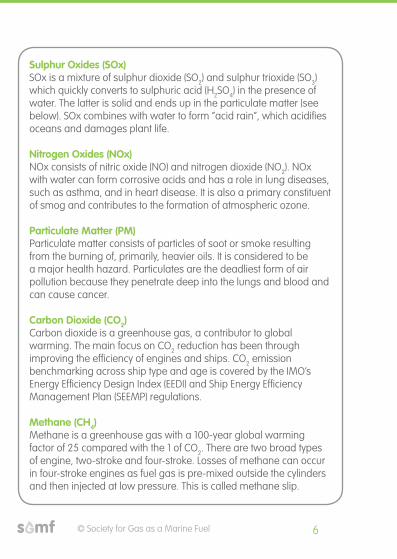
Sulphur Oxides (SOx)SOx is a mixture of sulphur dioxide (SO2) and sulphur trioxide (SO3) which quickly converts to sulphuric acid (H2SO4) in the presence of water. The latter is solid and ends up in the particulate matter (see below). SOx combines with water to form “acid rain”, which acidifies oceans and damages plant life.
Nitrogen Oxides (NOx)NOx consists of nitric oxide (NO) and nitrogen dioxide (NO2). NOx with water can form corrosive acids and has a role in lung diseases, such as asthma, and in heart disease. It is also a primary constituent of smog and contributes to the formation of atmospheric ozone.
Particulate Matter (PM)Particulate matter consists of particles of soot or smoke resulting from the burning of, primarily, heavier oils. It is considered to be a major health hazard. Particulates are the deadliest form of air pollution because they penetrate deep into the lungs and blood and can cause cancer.
Carbon Dioxide (CO2)Carbon dioxide is a greenhouse gas, a contributor to global warming. The main focus on CO2 reduction has been through improving the efficiency of engines and ships. CO2 emission benchmarking across ship type and age is covered by the IMO’s Energy Efficiency Design Index (EEDI) and Ship Energy Efficiency Management Plan (SEEMP) regulations.
Methane (CH4)Methane is a greenhouse gas with a 100-year global warming factor of 25 compared with the 1 of CO2. There are two broad types of engine, two-stroke and four-stroke. Losses of methane can occur in four-stroke engines as fuel gas is pre-mixed outside the cylinders and then injected at low pressure. This is called methane slip.
6
envi
ronm
enta
lte
chni
cal
safe
tyco
mm
erci
al
Emissions levels of fuels
SOx emissions depend on the amount of sulphur in the fuel. The gas used for LNG production is cleaned prior to liquefaction. Typical sulphur specifications in LNG are less than 30 parts per million (ppm) of total sulphur. This calculates to about 0.004% of sulphur by mass. LNG sulphur levels are therefore 1/875th of current heavy fuel oil (HFO) limits and 1/25th of future ECA limits. In comparison marine diesel oil (MDO) contains about 1% sulphur and marine gas oil (MGO) 0.1% sulphur. EN 590 diesel (road fuel diesel used by inland waterway vessels in Europe) has only 0.001% of sulphur. MDO and HFO would need scrubber technology to comply with ECA limits.
NOx emissions are very dependent on engine load and technology. None of the oil-fuelled options are able to meet Tier III limits
unaided. HFO has NOx levels marginally higher than, but generally comparable with, MDO. Oil-fired systems will need to be equipped with Selective Catalytic Reduction (SCR) technology or Exhaust Gas Recirculation (EGR) to reduce NOx emissions to levels comparable with LNG-fuelled engines. Some LNG engines may also need SCR.
LNG produces minimal quantities of particulate matter but dual-fuel engines using LNG and diesel will create PM. Using LNG reduces PM emissions compared with HFO engines by about 90%. MDO is also better than HFO on PM. What is an EmissionControl Area?
An Emission Control Area (ECA) is an area in which the emission limits for SOx (sulphur oxides) and NOx (nitrogen oxides) are lowered to reduce their impacts on health and the environment.
7
HawaiianIslands
U.S. West CoastU.S. East Coast
North Sea
Baltic
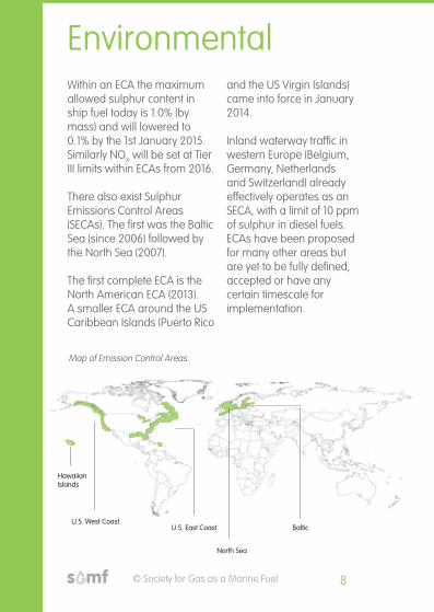
Within an ECA the maximum allowed sulphur content in ship fuel today is 1.0% (by mass) and will lowered to 0.1% by the 1st January 2015. Similarly NOX will be set at Tier III limits within ECAs from 2016.
There also exist Sulphur Emissions Control Areas (SECAs). The first was the Baltic Sea (since 2006) followed by the North Sea (2007).
The first complete ECA is the North American ECA (2013). A smaller ECA around the US Caribbean Islands (Puerto Rico
Environmental
8
Map of Emission Control Areas.
and the US Virgin Islands) came into force in January 2014.
Inland waterway traffic in western Europe (Belgium, Germany, Netherlands and Switzerland) already effectively operates as an SECA, with a limit of 10 ppm of sulphur in diesel fuels.ECAs have been proposed for many other areas but are yet to be fully defined, accepted or have any certain timescale for implementation.

envi
ronm
enta
lte
chni
cal
safe
tyco
mm
erci
al
How will ECAs be regulated?
Each country implements the IMO rules under its own laws and will enforce the law through national procedures. Various penalty regimes have been suggested, including:
• Large fines
• Prison sentences
• A vessel not being allowed to leave port until it has the right amount of fuel on board with the correct sulphur content
• A vessel being detained in its next port of call if the results of sampling come in late
• Fines based on what a ship could earn on cargo / fuel costs
Are there alternative options?
ECA regulations specify that NOx and SOx emissions must be reduced but are not specific about how this should be achieved. So there are various options for meeting the tighter emissions limits. Three options are generally regarded as the main alternatives: a switch to MGO, installation of scrubbers, or a switch to a variety of other fuels.
MGO
Marine Gas Oil (MGO) and Marine Diesel oil (MDO) can be used in many existing ship engines that have traditionally operated on heavy fuel oil (HFO). MDO tends to create more particulate matter and potentially SOx – so would need careful specification to ensure compliance with ECA limits. MGO generally comprises lighter hydrocarbons and is more likely to meet ECA limitations.
9

Again, the exact specification requires careful analysis before purchase. Therefore MGO may be a direct replacement option on a technical basis. However, it costs substantially more than HFO.
Scrubbing
Ships may continue to burn HFO in their engines if they then treat the exhaust gases to reduce SOx and NOx emissions to comply with the limits. CO2 production is not reduced. Scrubbers can be fitted to the engine exhaust system. The cost of installation is significant, and the space requirements and weight of the equipment will also need to be considered.
Scrubbers usually remove only SOx. Disposal of the waste products may also be an issue. Disposal at sea would lead to acidification – so many European port states are imposing limits on marine discharges from scrubber systems. Disposal
onshore is allowed only at a limited number of specialist centres and may be very expensive.
Additional NOx abatement technology will need to be fitted to most vessels to comply with Tier III limits. This uses a catalytic process (SCR) based on injecting urea into the exhaust gas.
Alternative fuels
A variety of alternative fuels are under consideration, with hydrogen seen by many as the fuel of the future in the long term. Hydrogen can be used in fuel cells to generate electricity, which can then be used to drive ship propulsion systems. A move towards electric propulsion using traditional engines as power generators is already under way.
Methanol is gaining some popularity as an alternative fuel. It is widely available as it is a petrochemical
Environmental
10
envi
ronm
enta
lte
chni
cal
safe
tyco
mm
erci
al
feedstock. It is also used in a limited way as an engine fuel (“wood alcohol”). A few ferries are trialling methanol on the Scandinavian/Baltic trades. However, it is highly toxic, is miscible with water, and has a low energy content per unit volume (energy density), so extra space is needed for fuel tanks. Methanol is only seen as interesting for bunker fuel if it is available at very low cost.
Liquid ethane carriers are also going to use ethane as fuel, just as some bulk LNG carriers use natural gas.
Why can’t I just use compressed natural gas (CNG)?
Compressed natural gas has been used for many years as a road transportation fuel and more recently for ships. A CNG-fuelled ferry is operating in Brazil. The problem with CNG, and to a lesser extent LNG, is its energy density. CNG stored at 250 times atmospheric pressure has an energy density of only about 9 million Joules/cubic meter (MJ/m3). LNG is more than twice as good as CNG at 22.2 MJ/m3. Petroleum fuels remain better at about 35 – 40 MJ/m3. This means that CNG vessels will have to have large fuel tanks or short distances between refuelling.
11

Who is doing it?
Interest in the use of LNG as a bunker fuel is growing rapidly, not just in ECAs but around the world.
Europe
Norway, the country that pioneered the technology, continues to push forward with more vessels. The European Union (EU), with 28 member states, is attempting to develop a co-ordinated approach to the use of LNG as a marine fuel, with a particular emphasis on the SECAs in the Baltic Sea and the North Sea/English Channel.
Most of the gas-fuelled vessels in service are in Norway. The first vessel entered service in 2000 and by the end of 2013 the Norwegian fleet had increased to more than 30 vessels.The lead nations within the EU are Denmark and Sweden but other countries
– including the Netherlands, Finland, Belgium, Germany and France – are also involved or have ordered vessels for their coastal or short-sea trades.
US / Canada
North America started later than Europe. However, the amount of activity over the last 18 months means that this region looks set to overtake Europe very quickly – primarily in the USA, but also in Canada. No LNG-fuelled vessels are yet in service but ten vessels are on order in the USA and another three in Canada. Many more will follow.
Far East
Japan and China are both very active in putting systems in place to enable LNG to be used as a marine fuel. However, it is South Korea that has built the first vessel. It is in service in Incheon harbour. China has two LNG-fuelled tugs in service
Technical
12
envi
ronm
enta
lte
chni
cal
safe
tyco
mm
erci
al
with CNOOC, one of the Big Three national oil and gas companies, and has ordered many inland waterway vessels. Japan looks set to order its first LNG-fuelled vessel, to operate in Tokyo Bay, later this year.
Rest of the world
Probably the world’s most advanced LNG-fuelled ship operates between Argentina and Uruguay. The gas-
fuelled, gas turbine-driven, high-speed ferry entered service in 2013. Brazil has a CNG ferry in operation.Indonesian ferry owner Pelni is examining converting its 26-ship fleet to LNG with national oil and gas company Pertamina. Australia is close to ordering its first gas-fuelled ferry to run between Melbourne and Tasmania.
None of these vessels operate in ECA zones.
0
10
20
30
40
50
60
70
Norway Other Europe US/Canada Rest of World
Number of gas fuelled ships
Other (order)
PSV (order)
Ferry (order)
Other Ships
PSV
Ferry
13
envi
ronm
enta
lte
chni
cal
safe
tyco
mm
erci
al
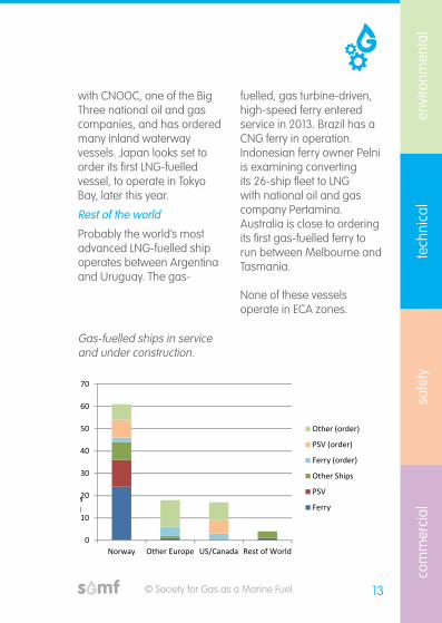
Gas-fuelled ships in service and under construction.
LNG-fuelled fleet
Car ferries currently (mid 2014) make up most of the LNG-fuelled fleet. They account for 21 out of 41 (51%) of the vessels in operation and 10 out of 38 (26%) of the vessels on order.
Offshore support vessels (OSVs) make up the second-largest contingent at 29% and 18% respectively. A variety of other ship types are in service, including marine patrol vessels, tugs, product tankers and general cargo ships.
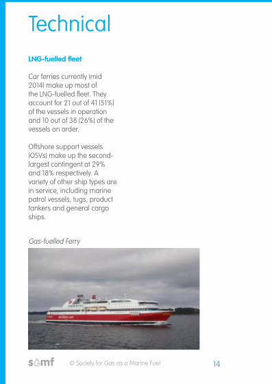
Gas-fuelled Ferry
Technical
14
LNG bunkering facilities
LNG is available for marine fuel use in the European ports of Antwerp, Amsterdam, Rotterdam, Stockholm and Zeebrugge. LNG can also be bunkered at the Norwegian ports of Bergen, Florø, Karmøy, Oslo and Risavika/Stavanger. In most cases this is by road tanker; however in Bergen there is a dedicated terminal and Stockholm has a bunker vessel called Seagas that provides LNG fuel. Ports in Finland, Italy and Spain have also loaded LNG as bunker.
All these ports are able to offer LNG to prequalified vessels that are compatible with the LNG-loading infrastructure. EU policy is to have at least one LNG bunkering port in each member state. About 10% of European coastal and inland ports will be included, a total of 139 ports. Coastal port
LNG infrastructure will be completed by 2020 and for inland ports by 2025. To date Denmark, Estonia, Finland, France, Germany, Norway, Spain, Sweden and the UK are considering where to locate LNG bunkering facilities.
There are several ports under development in North America, mostly in the Gulf of Mexico and around the Great Lakes, but also for ferry operations on the west coast
South Korea is able to offer LNG bunkering in the port of Incheon and is looking at a second facility at Busan. Elsewhere in Asia, Singapore, Japan and China are looking at LNG bunkering facilities.
15
envi
ronm
enta
lte
chni
cal
safe
tyco
mm
erci
al

Projections for the future
There is no question that LNG as a marine fuel has arrived; what we have yet to see is how large the industry will grow to and how quickly.
The industry has made several forecasts but as yet there is little alignment between them. Lloyds Register provided a detailed review of the potential growth scenarios in 2012. Its optimistic scenario predicted about 2,000 ships by 2025. This would be an average of about 150 ships per year, significantly more than the 14 ships delivered in 2013 and the 22 ships expected in 2014. Most of the growth in the Lloyds Register scenario takes place after 2020, when the IMO is proposing to impose worldwide sulphur reductions. DNV GL’s latest forecast (2014) appears to extrapolate from recent deliveries and so predicts
higher gas-fuelled ship numbers early, growing to a total of 3,200 vessels by 2025.
Other commentators have looked at the overall size of the fuel market and at how gas-fuelled ships would impact the global, bulk LNG business. Most of these forecasts are significantly less optimistic than the DNV GL fuel forecasts. Most commercial commentators – including Poten & Partners, Wood Mackenzie, CERA and Total – predict 20 – 30 mtpa of LNG by 2030. This would require about a 10% growth (20% for the most optimistic scenario) in today’s LNG production just for fuel use. LNG industry commentators such as BG Group are already suggesting that the LNG business will be supply-constrained for its traditional business model over this period.
Technical
16

What does a LNG-fuelled ship look like?
The fuel storage and use systems on a LNG-fuelled vessel differ to those on a conventional oil-fuelled ship. The requirements for an LNG-fuelled ship are currently being developed by IMO under the International Code of Safety for Ships using Gases or other Low Flashpoint Fuels (IGF Code). An interim set of rules is currently in place under MSC.285 (86). The IGF Code is currently being finalised and is expected to be released in the next version of SOLAS (Safety Of Life At Sea) in 2017.
This section discusses the general principles of ship design influenced by the IGF Code. Specialist consultancies and classification societies will be able to provide more specific advice.
17
envi
ronm
enta
lte
chni
cal
safe
tyco
mm
erci
al

Ship design
The factors to be considered during ship design are:
• Protection of the LNG storage tank and LNG/gas pipework from damage through collisions with other vessels and/or cargo or by dropped objects
• Redundancy of fuel systems to ensure that the vessel can continue to navigate if one system is damaged or fails
• Minimisation of any hazards provided by the use of gas as fuel
• Safety systems that provide a safe shut-down of hazardous systems and removal of their inventories to prevent the build-up of potentially explosive atmospheres
Most discussion currently surrounds the location of the LNG storage tanks and how far these need to be sited from the outer hull to avoid damage. Type C tanks have particular issues as their cylindrical shape is not easily accommodated in a space-efficient way in many parts of the hull.
LNG storage
The IGF Code is specifically concerned with monitoring the conditions within the tank (temperature and pressure), providing pressure-relief systems to dispose of gas safely in emergency scenarios, as well as boil-off gas management systems to control tank pressure during normal operations and to ensure that leaks are minimised by pipework design and/or by providing specific protection for a ship’s structural elements.
Technical
18

Ship fuel systems
The code provides specific advice on pipe design and layout between the LNG supply and the engines. LNG is very cold so the pipework (up to the point where the LNG is evaporated) must be allowed to contract without damage as it cools. Valves must be included to isolate the LNG storage tank or any other significant volume of LNG. If the pipes start to warm, pressure-relief valves must be provided to allow vapour to escape.
19
envi
ronm
enta
lte
chni
cal
safe
tyco
mm
erci
al
As with the LNG storage tanks, leaks, both LNG or gas, must be detected and contained. This is typically achieved by using a pipe-in-pipe (or duct) system with the LNG running through the inner pipe and a leak detection system provided in the outer pipe.
m/t Bit Viking with two 500m3 Type C tanks

Control systems
The engines, LNG tanks and fuel systems should be capable of being monitored, controlled and shut down from outside any potentially gas containing space. Suitable instrumentation should be provided to monitor tank levels, pressures and temperatures, to review the operation of ventilation systems, and to detect the escape of gases or – in the worst case – the outbreak of fires.
An Emergency Shut-Down (ESD) system is required. It should be capable of being triggered manually from multiple locations on the ship and automatically by specific occurrences, for example gas detection. Safety monitoring systems should have their own dedicated and independent control systems.
Redundancy of the fuel system is considered essential. This is preferably based on multiple LNG tanks, each with its own fuel system providing fuel to multiple engines.
Power generation & propulsion
The code covers gas-only engines, dual-fuel gas and oil engines, multi-fuel engines (such as methanol), gas turbines and fuel cells. Redundancy is the key issue – with a vessel needing to continue to operate with the failure of one engine. The use of multiple engines, each in a separate machinery space, is the preferred option in the code.
For dual- and multi-fuel engines, an automatic fuel changeover system is required, which must operate on the failure of one fuel supply system.
Technical
20
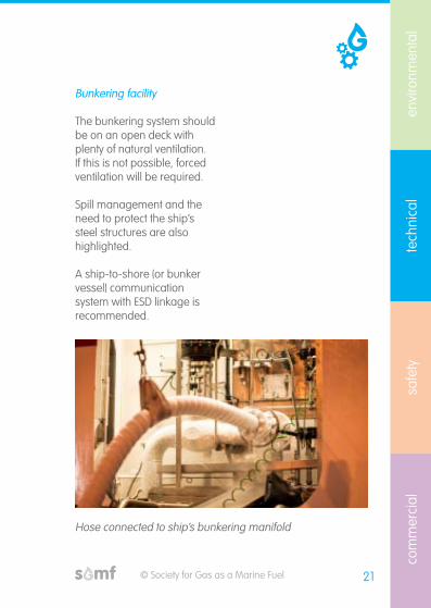
Bunkering facility
The bunkering system should be on an open deck with plenty of natural ventilation. If this is not possible, forced ventilation will be required.
Spill management and the need to protect the ship’s steel structures are also highlighted.
A ship-to-shore (or bunker vessel) communication system with ESD linkage is recommended.
Hose connected to ship’s bunkering manifold
21
envi
ronm
enta
lte
chni
cal
safe
tyco
mm
erci
al

What does a bunkering system look like?
There are four different options for refuelling an LNG-powered vessel.
LNG terminals
LNG terminals can transfer LNG to ships directly without using any intermediate transfer system. This,
Technical
22
however, will require the ship needing fuel to sail to the LNG terminal. Large terminals will have storage tanks that operate at atmospheric pressure and bunkering will take place using pumps. This type of terminal will be supplied by large LNG tankers and will often be the supply source for road tankers and bunker vessels. Small terminals are similar to road tankers and most bunker vessels as
Bunker vessel
LNG terminal
Bunkering options
LNG Container
Road tanker

23
they use pressurised tanks to store their LNG. They will receive LNG either from LNG carriers or manufacture it themselves. LNG transfer will normally be by pressure differential.
Bunker vessels
LNG can be transferred from bunker vessels or even small LNG carriers, which can be moored alongside ships anywhere in a port. Transfer of LNG can be by pressure difference or, if high speeds are required, by dedicated LNG pumps. There are no physical restrictions on the amount of LNG that can be stored on a bunker vessel, so one bunker vessel may be able to service more than one ship.
Road trucks
LNG road tankers are limited by weight through road transport legislation so bunkering via a road tanker
typically serves the smaller end of the LNG transfer market. Emptying a single road tanker can be achieved using a pressure differential between the tanker and the ship and typically takes about an hour. Multiple road tankers can be unloaded simultaneously, depending on the LNG volume required and the piping arrangement.
Containerised LNG
LNG tanks can be provided within standard 20 foot and 40 foot container sizes and comprise a Type C LNG tank, similar to a road tanker, inside a container-shaped steel frame. Many road transport operations now use LNG containers on flat-bed trucks rather than custom-built road tankers.
For gas as a marine fuel, LNG could be provided and stored by such “cassette”-type cell systems. Whole containers would be lifted
envi
ronm
enta
lte
chni
cal
safe
tyco
mm
erci
al

The disadvantages of this technology are that it is not space-efficient, particularly if located within the hull, and is relatively expensive.
The iconic, free-standing, Moss Rosenberg spheres are extremely robust in terms of strength and operability but take up very large amounts of space. It is therefore difficult to envisage any LNG-fuelled ships adopting this tank technology. Self-supporting Prismatic type B (SPB) tanks are effectively cuboid in shape and can be designed to fit comfortably within most hull shapes. The tanks have internal strengthening and structural systems which make them very robust but also expensive and relatively heavy.
Membrane containment systems use thin metallic barriers supported by the strong hull structure via load-bearing insulation
or driven on board and connected to the fuel system. Empty tanks would be disconnected and removed.
Bunkering system components
The bunkering system consists of an LNG tank to hold the LNG, a transfer system that connects this to the tank on the ship that is to be filled, and a control system to enable the transfer.
LNG Storage tanks
A variety of LNG storage tanks are (or will be) available to hold LNG. Most of these tanks have operated successfully on LNG carriers operating in the bulk international LNG business.IMO Type C tanks are pressure vessels whose internal pressure may be increased to several times atmospheric pressure. This is very attractive for the LNG bunkering process as it avoids venting any cold gas.
Technical
24

25
arrangements. The membrane is subject to deflection loads as the hull moves, and therefore requires a duplicate “secondary barrier” to protect the hull in case of failure of the primary membrane. Membrane tanks can be made into any shape so can be used space efficiently within a hull. However, the membrane is thin and can be damaged by “sloshing”, waves generated within the LNG tank by ship movement. The shape of the tank and the strength of the insulation needs careful consideration to avoid sloshing issues.
LNG bunker transfer system
The LNG bunker transfer system consists of valves, a flexible piping system, safety valves and a connector system to the ship’s pipework and control system.
envi
ronm
enta
lte
chni
cal
safe
tyco
mm
erci
al
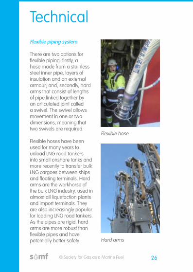
Flexible piping system
There are two options for flexible piping: firstly, a hose made from a stainless steel inner pipe, layers of insulation and an external armour; and, secondly, hard arms that consist of lengths of pipe linked together by an articulated joint called a swivel. The swivel allows movement in one or two dimensions, meaning that two swivels are required.
Flexible hoses have been used for many years to unload LNG road tankers into small onshore tanks and more recently to transfer bulk LNG cargoes between ships and floating terminals. Hard arms are the workhorse of the bulk LNG industry, used in almost all liquefaction plants and import terminals. They are also increasingly popular for loading LNG road tankers. As the pipes are rigid, hard arms are more robust than flexible pipes and have potentially better safety
Technical
26
Flexible hose
Hard arms

27
performance. That said, the continuous movement of the swivels during bunkering may lead to maintenance and component lifetime issues.
Emergency release coupling
Emergency release couplers (ERCs) have been introduced to limit – indeed almost eliminate – LNG spills should the system need to be disconnected in an emergency. An ERC consists of two valves that close automatically in an emergency shut-down scenario. Between the two valves is a coupler that can break away, allowing separation of the two vessels with the only spillage being the small amount of LNG trapped between the two valves.
Control systems
Best practice is to connect the two LNG tanks and control systems to allow each side
to monitor the filling process and prevent any hazardous scenarios – such as over-filling or over-pressurisation – developing.
Emergency release coupler
envi
ronm
enta
lte
chni
cal
safe
tyco
mm
erci
al

the seller of the LNG. In this capacity the PIC will provide the correct amount and quality of LNG. The PIC is responsible for the safety of the LNG supply and transfer equipment. The PIC will also be responsible for complying with any local safety, environmental and maritime requirements. If, at any stage, the transfer process fails to comply with the local regulations, the PIC should terminate the transfer.
The choice of filling method will depend on many factors, including: the compositions of the LNG in the tank and the LNG fuel; the temperatures of both LNG volumes; the filling rate; and the pressure ratings of the LNG tanks.
The bunkering process is summarised in the flow diagram on the right.
Bunkering process
Bunkering an LNG-fuelled vessel involves many stakeholders and has several stages.
The master of the vessel to be fuelled retains control over the ship. The master is acting on behalf of and in the interests of the buyer of the LNG. In this capacity the master must approve the quantity and quality of the LNG that will be bunkered. The master must also ensure that the LNG transfer process is safe and that environmental impacts are minimised. If these basic requirements do not continue to be met at any time during bunkering, the master has the right to terminate the process.
The Person In Charge (PIC) is in control of the transfer of LNG. In most scenarios the PIC will act on behalf of
Technical
28

29
Flow diagram of a typical bunkering process
envi
ronm
enta
lte
chni
cal
safe
tyco
mm
erci
al
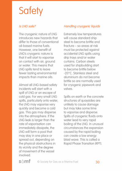
Handling cryogenic liquids
Extremely low temperatures will cause standard ship steel to become brittle and fracture – so areas at risk must be protected against accidental LNG spills using drip trays and/or water curtains. Carbon steels used for shipbuilding start to become brittle below -20°C. Stainless steel and aluminium do not become brittle so are normally used for cryogenic pipework and valves.
Spills on earth or the concrete structures of quaysides are unlikely to cause damage but may take some time to vaporise and disperse. Spills of cryogenic fluids onto water lead to very rapid boiling of the LNG. In unusual circumstances the expansion caused by the rapid boiling can create a low energy blast wave. This is called a Rapid Phase Transition (RPT).
Is LNG safe?
The cryogenic nature of LNG introduces new hazards that differ to those of conventional oil-based marine fuels. However, one benefit of LNG’s cryogenic nature is that it will start to vaporise on contact with air, ground or water. This means that LNG spills tend to leave fewer lasting environmental impacts than marine oils.
Almost all LNG-based safety incidents will start with a spill of LNG or an escape of cold gas. For very small LNG spills, particularly onto water, the LNG may vaporise very quickly and become a cold gas. This gas may disperse into the atmosphere. If the LNG leak is larger than the rate of vaporisation can immediately dissipate, the LNG will form a pool that may stay in one place or spread out, depending on the physical obstructions in its vicinity and the degree of movement of the vessel involved.
Safety
30
envi
ronm
enta
lte
chni
cal
safe
tyco
mm
erci
al
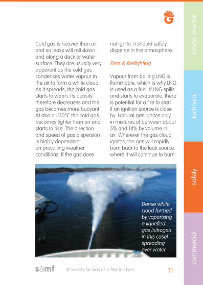
Cold gas is heavier than air and so leaks will roll down and along a deck or water surface. They are usually very apparent as the cold gas condenses water vapour in the air to form a white cloud. As it spreads, the cold gas starts to warm. Its density therefore decreases and the gas becomes more buoyant. At about -110°C the cold gas becomes lighter than air and starts to rise. The direction and speed of gas dispersion is highly dependent on prevailing weather conditions. If the gas does
not ignite, it should safely disperse in the atmosphere.
Fires & firefighting
Vapour from boiling LNG is flammable, which is why LNG is used as a fuel. If LNG spills and starts to evaporate, there is potential for a fire to start if an ignition source is close by. Natural gas ignites only in mixtures of between about 5% and 14% by volume in air. Wherever the gas cloud ignites, the gas will rapidly burn back to the leak source, where it will continue to burn
31
Dense white cloud formed by vaporising a liquefied gas (nitrogen in this case) spreading over water

regarded in the marine and hydrocarbon industries as best practice. This view is based on their high-quality, robust safety systems and overall attention to detail in design, solid construction and stringent operational practices. These factors combine to minimise accidents, incidents and product releases.
Multiple layers of protective measures are implemented to prevent a hazardous scenario escalating into an actual safety incident.
Layers ofprotectionprinciples
until it is extinguished or all the LNG has combusted.In very specific circumstances the ignition of a fire may be so violent that a form of explosion can occur.
Designing in safety
The greatest benefits of safety analysis are at the design stage, which is when most proposed safety improvements can be accommodated relatively easily. During and after construction some safety improvements may no longer be possible at reasonable cost, for example if they require the altering or moving of major systems or hull components.
The bulk LNG industry has a good safety record, having developed very rigorous design guidelines for both ships and shore facilities, as well as high standards of training and operational procedures. LNG facilities and LNG carriers are
32
Safety
envi
ronm
enta
lte
chni
cal
safe
tyco
mm
erci
al
33
Simultaneous failure of multiple layers of protection is unlikely.
Safety distances and exclusion zones
Safety distances are designed to keep ignition sources away from the LNG and any potential leaks, while simultaneously minimising the potential for scenarios that could lead to damage, such as collisions. The size of safety zones can be calculated by one of two generally accepted systems. The choice will usually be at the discretion of the local regulator and may also depend on the type of bunkering being used.
The maritime industry has generally used a deterministic approach, in which distances are calculated for certain failure scenarios. These scenarios need to be credible, which
is normally where the arguments begin. Some supposedly credible scenarios may lead to large safety distances, of perhaps up to 100 metres or more.
The alternative –probabilistic – approach predominates in many onshore LNG facilities. It uses the same consequence calculations as the deterministic method but also assigns probabilities or frequencies to the chance of an event occurring. The safety distances generated are examined on the maximum risk to an individual worker/member of the public and the societal risk to the wider community. Safety distances here can be small to very small. The weakness of this method is the ability of the hazard assessor to source appropriate frequency data and independently assess hazard scenarios.
34
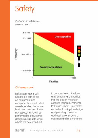
to demonstrate to the local and/or national authorities that the design meets or exceeds their requirements. Risk assessment is normally carried out during the design and planning phases – addressing construction, operation and maintenance.
Probablistic risk-based assessment
Risk assessment
Risk assessments will need to be carried out on equipment and components, on individual vessels, and on the whole bunkering process. Some risk assessments will be performed to ensure that design work is safe while others will be carried out
Safety

envi
ronm
enta
lte
chni
cal
safe
tyco
mm
erci
al
35
The results of such risk assessments must be incorporated into the operational and maintenance procedures as appropriate. Full risk assessment consists of much more than just a Quantitative Risk Assessment! A HAZard and OPerability (HAZOP) study – in which each major equipment component is examined for a variety of mal-operations and the impact of the effects of poor performance is quantified – is particularly appropriate.
Risk assessment is not a one-off process; it needs to be repeated every time something significant changes. This may be a new vessel to be fuelled (if substantially different from others fuelled), the use of different bunkering equipment, and/or changes in operating procedures.
Safety management systems
Management systems and procedures must reinforce staff behaviours around the implementation of safety to ensure that policies are effective. Alongside risk assessment, the use of safety manuals, appropriate working procedures/practices and training are crucial.
Any work also needs to be seen in the context of the whole plant or vessel – to ensure that one task does not interfere with or cause safety concerns for other tasks/workers. Particular emphasis should be placed on non-routine operations, where it may not be straightforward to understand all the hazards involved.
Modifications should go through a risk assessment process before being authorised.
36
How do I plan for emergencies?
Accidents can happen. Planning therefore should consider all possible eventualities, so that if the worst happens, the most appropriate response clicks in.
Generally there should be two levels in an emergency plan. The first level looks after the site of a potential incident. The second level looks after the wider community.
The site emergency response would probably involve the bunker company/facility owner and fire and ambulance authorities. The purpose of this is to handle the immediate hazard, controlling and extinguishing any fire and treating any injured people.
The offsite emergency response plan aims to handle the consequences
Will simultaneous operations be allowed?
Whether simultaneous operations will be allowed will be for the port authority and/or the safety regulator to decide, on the basis of risk assessments and safety management systems.
There is nothing in the regulations forbidding simultaneous operations, but they introduce additional hazards, for example the dropping of a container on the bunker vessel, or the consequences of an incident being greater. For example, passengers are likely to be more vulnerable during boarding and also represent multiple potential ignition sources because of their mobile phones and/or vehicle engines.
Safety
envi
ronm
enta
lte
chni
cal
safe
tyco
mm
erci
al
The emergency plan needs to be tested at least annually. Tests can range from desk-top exercises involving only senior staff from the emergency services to full-blown simulated emergencies, with fire appliances in attendance and ambulances treating simulated casualties.
of an event for the wider community. Typically the police are the main agency and the local authority will need to be involved, particularly if a public evacuation is required. Dealing effectively with media interest is an important part of this activity. Both the bunker supplier and the ship owner should be involved.
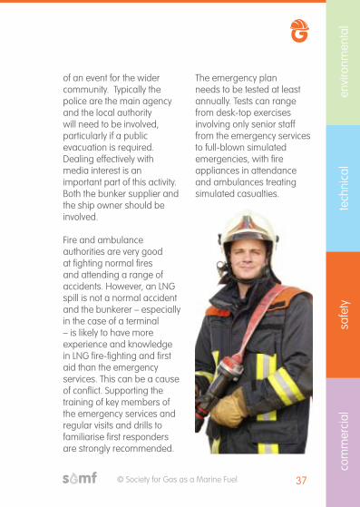
Fire and ambulance authorities are very good at fighting normal fires and attending a range of accidents. However, an LNG spill is not a normal accident and the bunkerer – especially in the case of a terminal – is likely to have more experience and knowledge in LNG fire-fighting and first aid than the emergency services. This can be a cause of conflict. Supporting the training of key members of the emergency services and regular visits and drills to familiarise first responders are strongly recommended.
37
38
There is concern over “regulatory clash”, the mismatch of onshore rules (frequently competence-based but with criteria set by operators and approved by regulators) with prescriptive shipping rules and IMO training systems.
Training for mariners
Gas-as-fuel training for mariners will come under the International Maritime Organisation’s (IMO’s) Standards of Training and Watchkeeping Committee (STCW). A four-level system is anticipated:
• Familiarisation of the crew with the ship and equipment. This is expected to be the responsibility of ship owners and managers and outside of STCW regulations.
• Basic training of all crew on a gas-fuelled vessel about the safety issues of natural gas
What training is required?
Working together
Bunkering is a two-stage process – one party supplying the fuel and the other receiving it. The two crews need to work together so both must be trained. It is probably not possible to train everyone in everything but the basic mental model between the two parties should be shared to enable understanding. Communication and co-ordination are key to successful and safe bunkering.
The main risks are thought to be associated with the ship being fuelled. The bunker vessel, terminal or road tanker staff would be bunkering every day and probably many times each day. The ship may bunker only infrequently (every several days or weeks). The quality of the receiving vessel and training of its crew are key to safe bunkering.
Safety

training and experience on operating (or training) ships.
Training for bunkervessel staff
From a regulatory point of view, bunker vessels are considered to be LNG carriers as they transport LNG cargo in bulk. The existing training requirements of STCW under the IGC Code would therefore apply to bunker vessels, rather than any system proposed under IGF. Some elements of the IGF code training process may also apply.
Training for terminal staff
It is normally a legal requirement for LNG import terminals and small liquefaction plants to provide training for their employees in the hazards of LNG and the company’s operating and maintenance procedures.
and how these should be dealt with on the vessel.
• Advanced training for all officers and engineering crew involved in the operation of the gas-fuelling system and the LNG-bunkering process.
• Equipment specific training, probably from the vendors, for the actual systems used on the ship. This too would lie outside the STCW code.
DNV GL has suggested an alternative approach for the advanced training that would involve separating out different learning requirements for deck and engineering staff, based on their actual roles within the gas/LNG storage, transfer and engine operation.
A variety of training methods are proposed, including training courses, simulator
40
envi
ronm
enta
lte
chni
cal
safe
tyco
mm
erci
al
39
40
Training for road tanker operators
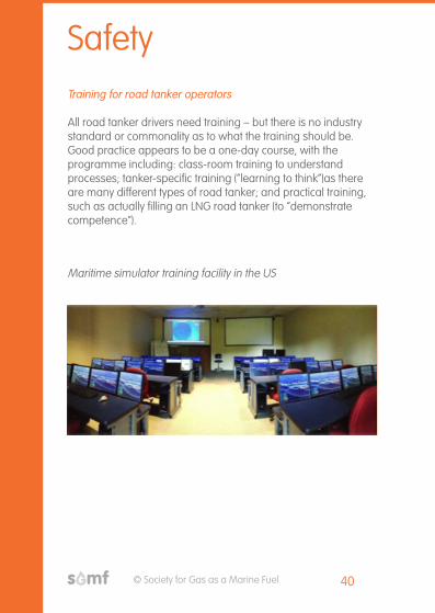
All road tanker drivers need training – but there is no industry standard or commonality as to what the training should be. Good practice appears to be a one-day course, with the programme including: class-room training to understand processes; tanker-specific training (“learning to think”)as there are many different types of road tanker; and practical training, such as actually filling an LNG road tanker (to “demonstrate competence”).
Safety
Maritime simulator training facility in the US
envi
ronm
enta
lte
chni
cal
safe
tyco
mm
erci
al
bunker (see diagram). The main reference price will be the cost of gas to customers, the gas market price. LNG bunker prices would probably be based on the market gas price plus the cost of producing and distributing LNG at small scale. Bulk, internationally supplied, LNG would compete with this price but would need to show that the upstream profit, where most of the risk is taken, is commensurate with other international gas trading options.
Comparing the economics of LNG bunker with oil is difficult, because they depend on the precise compositions of the LNG and the oil. They also depend on engine type and efficiency.Build-up of LNG bunker prices
How much does LNG cost?
There are essentially two types of LNG trading. Firstly, there is the international bulk trade, in which LNG moves from one country to another, often over very long distances, in large LNG carriers. Secondly, there are the smaller local producers that produce LNG for local markets. The price of LNG will depend on which of these models is used and where in the world it is sourced from.
Gas and LNG are sold on an energy basis, typically in British thermal units (Btu). (Because a Btu is a very small measure of energy, a Btu is about 4 calories, the most common unit is a million Btu, or MMBtu.) The price of gas varies by location, from country to country and within countries.
The price of LNG as bunker needs to be built up from the gas well to the LNG
Commercial
4241

42
If price insufficientCargo diverted
Gas M
arket Price Minus
Gas M
arket Price Plus
Bunker Price
Alternative Gas M
arket PriceBulk LN
G Im
port Term
inalGas Transm
ission System
Gas Fields (on or off shore)
Bulk LNG Liquefaction
Gas Treatment
Terminal
Bulk LNG Shipping
Bulk LNG Shipping
Gas M
arket Price
Small LN
G ships
Small LN
G Liquefier
Bunker VesselBunkering Term
inalQ
uayside BunkeringContainerised LN
G
Bunkering
LNG
Road Transport
Commercial

envi
ronm
enta
lte
chni
cal
safe
tyco
mm
erci
al
As LNG contracts are generally based on traded oil and/or gas references, they can be hedged. It is easy to envisage USA LNG bunker sales contracts being based on the price of gas at Henry Hub and European bunker prices being based on either NBP prices or those at the Dutch equivalent, the Title Transfer Facility (TTF).
The oil equivalents include the price of oil from Brent (an oil field in the UK sector of the North Sea), West Texas Intermediate (WTI) in the USA, and the Japan Crude Cocktail (JCC) price in Asia (also referred to as
Over the long term, LNG delivered to a ship as fuel is expected to cost less than MDO and to be generally comparable with HFO.
LNG contracts normally include some form of price indexation. Historically this has been against an oil or a basket of oils. Increasingly, gas indices are being used in price-formation mechanisms – usually Henry Hub in the USA or the National Balancing Point (NBP) in the UK. The price of the LNG therefore generally rises and falls in line with oil or gas prices, depending on how it is indexed.
The corresponding prices for oil after conversion to energy terms (as of June 2014)
US$ / mmBTU Europe(Rotterdam)
US(Houston)
Far East (Tokyo)
HFO 14 - 15 14 - 15 16 - 17
MDO 20 - 21 23 - 24 21 - 22
Natural Gas 7 - 8 4 - 5 15 - 16
43

44
the Japan Customs-cleared Crude price).
What commercial agreements will I need?
There are two operations that need to happen for LNG bunkering to take place. Firstly, the bunkerer has to purchase LNG from a bulk importer or local liquefaction company. Secondly, the ship owner/operator has to purchase LNG fuel from the bunkerer. In between LNG supply and ship bunkering may be some form of delivery contract to cover the costs incurred by third parties, for example road truck operators.
The LNG supply side is well covered by existing commercial practices. Many different models exist but companies and specialist energy lawyers should be confident of the continuation of these models with relatively minor modifications.
On the LNG delivery side there is no definite answer as yet. However, existing oil bunkering contracts – and Bunker Delivery Notices (BDNs) – are not dissimilar to the documentation used in the bulk transportation of LNG. So alignment should be possible. One of the technical committees of the European Sustainable Shipping Forum is developing a standardised LNG BDN.
Differences betweenLNG & oils
LNG differs from oils in that it is an evaporating liquid. Any heat ingress boils off some of the LNG to create what is called Boil-Off Gas (BOG). It consists of the most volatile components, normally nitrogen and methane.
As BOG is generated, the composition (or quality) of the LNG gradually changes. Over many days or weeks significant changes in
Commercial
envi
ronm
enta
lte
chni
cal
safe
tyco
mm
erci
al
volume and the density the mass of LNG transferred is calculated. To ensure accuracy – this type of LNG custody transfer is accurate to ±1% – many corrections need to be made for cargo temperature and pressure, list and trim of the LNG tanker, and from calibration of the tanks and the measuring instrument. The LNG importers’ group GIIGNL provides detailed guidance on this method.
A similar method could be used on a bunker vessel. The apparently laborious measurement and corrections are normally performed by computers in the custody transfer system and so require only occasional cross-checking and calibration.
The alternative from the LNG road fuel market, and to a certain extent LNG road trucking, is to use a mass measurement device. Road tankers are frequently
composition can occur. This is called “aging” or “weathering”. Sampling for quality measurement therefore needs to take place close to the time of LNG bunkering, preferably at the same time, but otherwise within a few hours.
Depending on the LNG tank type, rate of bunkering and composition of the LNG, BOG may be generated during bunkering. In the bulk LNG industry this BOG is returned to the supplier (for example, the bunker vessel) and may have a financial value. Therefore two flows potentially need to be measured, both the liquid LNG and the gaseous BOG.
Quantity measurement
LNG in bulk has always been measured by recording tank levels before and after the transfer. The density is calculated from a LNG sample taken at the same time and using this known
45
46
loaded on weighbridges to accurately determine the mass of LNG transferred. Filling LNG-fuelled trucks uses a system similar to a petrol/gasoline or diesel pump with a totaliser system based on a mass flow meter. Coriolis meters are the normal technology choice.
Sampling & quality calculation
The largest inaccuracy in traditional LNG custody transfer systems stems not from the flow measurement but from the calculation of the density. The density is calculated accurately from a composition; the difficult stage is sampling for the composition. As with oil, a sample of LNG must be taken from the transfer pipe as close as possible to the manifold. Unlike oil, the sample must be vaporised to analyse the composition of the resulting gas in a chromatograph.
Vaporisation must be very fast to prevent volatile components leaving prematurely and to ensure that no residual components are left as liquid. This analysis is used to calculate the density and the calorific value of the LNG. As with oil, gas samples need to be kept in case of appeal by one party against another.
Commercial
Contact Us
Address:50 Liverpool Street, London, EC2M 7PY, UK
Telephone: +44 (0) 20 3637 1455
Website:www.sgmf.info
Email: [email protected]
LinkedIn: Society for Gas as a Marine Fuel
Twitter:@sgmf2014
The Society for Gas as a Marine Fuel (SGMF) was established to promote best practice in the use of gas as a marine fuel. The society’s ultimate goal is to develop and produce definitive guidelines so that the process of using gas as a marine fuel can be undertaken safely and consistently worldwide. In this way, all the players along the gas supply chain will be able to realise the benefits that stem from its use.
47