Environmental Statement and Technical Appendices · HAZID Hazard Identification HAZOP Hazards and...
174
The Planning Act 2008 The Infrastructure Planning (Applications: Prescribed Forms and Procedure) Regulations 2009 Regulation 5(2)(a) and 5(2)(g) The Proposed Knottingley Power Plant Order Environmental Statement and Technical Appendices PINS application document reference: 6.1 PINS project reference: EN010050 Author: Parsons Brinckerhoff and Sinclair Knight Merz Date: September 2013 Version A (submission – September 2013) Knottingley Power Limited Tricor Suite, 7th Floor, 52/54 Gracechurch Street London England EC3V OEH Email: [email protected] Web: www.knottingleypower.co.uk
Transcript of Environmental Statement and Technical Appendices · HAZID Hazard Identification HAZOP Hazards and...
The Planning Act 2008
The Infrastructure Planning (Applications: Prescribed Forms and Procedure) Regulations 2009 Regulation 5(2)(a) and 5(2)(g)
The Proposed Knottingley Power Plant Order
Environmental Statement and Technical Appendices
PINS application document reference: 6.1 PINS project reference: EN010050 Author: Parsons Brinckerhoff and Sinclair Knight Merz Date: September 2013 Version A (submission – September 2013)
Knottingley Power Limited Tricor Suite, 7th Floor, 52/54 Gracechurch Street London England EC3V OEH Email: [email protected] Web: www.knottingleypower.co.uk


Knottingley Power Project Environmental Statement
Introductory Sections
Knottingley Power Limited
September 2013

Knottingley Power Project Environmental Statement - Introductory Sections
September 2013 Page 1
CONTENTS
Page
LIST OF ABBREVIATIONS
INTRODUCTION 9
1 INTRODUCTION 11
1.1 Knottingley Power Limited 11
1.2 The Knottingley Power Project Team 11
1.3 Knottingley Power Project 11
1.4 Planning Policy Context 13
1.5 Development Consent Order / Overview of the Consenting Process 14
1.6 Environmental Impact Assessment Process 15
RATIONALE FOR DEVELOPMENT 19
2 RATIONALE FOR DEVELOPMENT 21
2.1 Introduction 21
2.2 Background 21
2.3 Meeting Energy Security and Carbon Reduction Objectives 21
2.4 The Need to Replace Closing Electricity Generating Capacity 22
2.5 Future Increases in Electricity Demand 24
2.6 The Urgency of Need for New Electricity Capacity 25
2.7 Summary 25
2.8 Benefits of the Development of the KPP 25
CONSENTING PROCESS / ENVIRONMENTAL IMPACT ASSESSMENT PROCESS 27
3 CONSENTING PROCESS / ENVIRONMENTAL IMPACT ASSESSMENT PROCESS29
3.1 Development Consent Order / Overview of the Consenting Process 29
3.2 Environmental Impact Assessment Process 35
3.3 Content of the Environmental Statement 40
ENVIRONMENTAL SCOPING 45
4 ENVIRONMENTAL SCOPING 47
4.1 Introduction 47
4.2 Environmental Scoping 47

Knottingley Power Project Environmental Statement - Introductory Sections
September 2013 Page 2
ALTERNATIVES 93
5 ALTERNATIVES 95
5.1 Introduction 95
5.2 CCGT Power Plant Site Selection 95
5.3 Gas Pipeline Route Evolution, Selection and Refinement 96
DESCRIPTION OF THE DEVELOPMENT 109
6 DESCRIPTION OF THE DEVELOPMENT 110
6.1 The Knottingley Power Project 110
6.2 Description of the CCGT Power Plant Site and its surroundings 111
6.3 Description of the CCGT Power Plant 112
6.4 CCGT Power Plant – Construction / Operation / Decommissioning 126
6.5 CCGT Power Plant – Safety Considerations 132
6.6 Description of the Grid Connection 133
6.7 Grid Connection – Construction / Operation / Decommissioning 134
6.8 Description of the Cooling Water Infrastructure 138
6.9 The Cooling Water Infrastructure – Construction / Operation / Decommissioning140
6.10 Description of the Gas Pipeline 140
6.11 The Gas Pipeline - Construction / Operation / Decommissioning 147
6.12 The Gas Pipeline – Safety Considerations 167
6.13 Other Consents / Permits / Licences Required for the KPP 170

Knottingley Power Project Environmental Statement - Introductory Sections
September 2013 Page 3
LIST OF ABBREVIATIONS
% percent
%ile Percentile
AADT Annual Average Daily Traffic
Aatm Atmospheric Absorption
Abar Screening by Obstacles
AC Alternating Current
Adiv Geometrical Divergence
ADMS Atmospheric Dispersion Modelling System
AGI Above Ground Installation
AGR Advance Gas Reactor
Agr Ground Effect
AIL Abnormal Indivisible Load
Amisc Miscellaneous Effects
AOD Above Ordinance Datum
AONB Area of Outstanding Natural Beauty
APIS Air Pollution Information System
AQAP Air Quality Action Plan
AQMA Air Quality Management Area
AQO Air Quality Objectives
AQS Air Quality Strategy
ASME American Society of Mechanical Engineers
ASWYAS Archaeological Services West Yorkshire Archaeology Services
AUT Automatic Ultrasonic Testing
BAP Biodiversity Action Plan
bar g bar gauge
BAT Best Available Technique
BGS British Geological Society
BPD Boring Proximity Distance
BRE Building Research Establishment
BS British Standard
C&I Commercial and Industrial
CAA Civil Aviation Authority
CBOA Commercial Boat Operators Association
CCGT Combined Cycle Gas Turbine
CCR Carbon Capture Ready
CCS Carbon Capture and Storage
CCTV Close Circuit Television
CD Cathodic Protection
CDM Construction, Design and Management
CEH Centre for Ecology and Hydrology

Knottingley Power Project Environmental Statement - Introductory Sections
September 2013 Page 4
CEMP Construction Environmental Management Plan
CEMS Continuous Emissions Monitoring System
CHP Combined Heat and Power
CIEH Chartered Institute of Environmental Health
CIRIA Construction Industry Research and Information Association
CL Critical Load
CLEA Contaminated Land Exposure Assessment
CO Carbon Monoxide
CO2 Carbon Dioxide
CoC Contaminants of Concern
COMAH Control of Major Accident Hazards
COSHH Control of Substances Hazardous to Health
CRTN Calculation of Road Traffic Noise
CS Core Strategy
CSM Conceptual Site Model
CSWMP Construction Surface Water Management Plan
CTMP Construction Transport Management Plan
CTP Construction Travel Plan
dB Decibels
DCLG Department for Communities and Local Government
DCO Development Consent Order
DCVG Direct Current Voltage Gradient
DECC Department for Energy and Climate Change
DEFRA Department for Environment, Food and Rural Affairs
DEMP Decommissioning Environmental Plan
DMBC Doncaster Metropolitan Borough Council
DMRB Design Manual for Roads and Bridges
DPD Development Plan Documents
DQRA Detailed Quantitative Risk Assessment
EA Environment Agency
EAL Environmental Assessment Levels
EART Environmental Assessment of Road Traffic
EcIA Ecological Impact Assessment
EH English Heritage
EHA English Heritage Records
EHO Environmental Health Officer
EIA Environmental Impact Assessment
EMS Environmental Management System
EPS European Protected Species
EPUK Environmental Protection United Kingdom
ES Environmental Statement
ESB Electricity Supply Board

Knottingley Power Project Environmental Statement - Introductory Sections
September 2013 Page 5
ESD Emergency Shutdown Device
ESR Environmental Scoping Report
EU European Union
FRA Flood Risk Assessment
GAC Generic Assessment Criteria
GCN Great Crested Newt
GIS Gas Insulated Switchgear
GLA Greater London Authority
GRF Gas Receiving Facility
GW GigaWatt
HA Highways Agency
HAP Habitat Action Plan
HAZCON Hazardous Construction
HAZID Hazard Identification
HAZOP Hazards and Operability
HCU Hybrid Cooling Units
HDD Horizontal Directional Drill
HGV Heavy Goods Vehicle
HIA Health Impacts Assessment
HNO3 Nitric Acid
HPA Health Protection Agency
HRA Habitats Regulations Assessment
HRSG Heat Recovery Steam Generator
HSC Hazardous Substances Consent
HSE Health and Safety Executive
IAQM Institute of Air Quality Management
IDB Internal Drainage Board
IEEM Institute of Ecology and Environmental Management
IEH Institute of Environment and Health
IfA Institute for Archaeologists
IGE Institute of Gas Engineers
IPC Infrastructure Planning Commission
IPPC Integrated Pollution Prevention and Control
JMU Joint Mobility Unit
JNCC Joint Nature Conservation Committee
kEgH+/ha.yr Estimated Acid Deposition per Hectare per Year
kgN/ha.yr Kilograms of Nitrogen per Hectare per Year
km kilometre
km2 Square Kilometres
kph kilometres per hour
KPL Knottingley Power Limited
KPP Knottingley Power Project
Knottingley Power Project Environmental Statement - Introductory Sections
September 2013 Page 6
kV kilo Volt
LA90 A weighted sound pressure level exceeded 90 % of the time
LAeq Equivalent Sound Pressure Level
LAeq,T Equivalent continuous A weighted sound Pressure level
LAeq,Tr Equivalent continuous A weighted sound Pressure level over a given time period
LAmax A-weighted Maximum Sound Pressure Level
LAQM Local Air Quality Management
LB Listed Building
LBAP Local Biodiversity Action Plan
LCA Landscape Conservation Area
LCPD Large Combustion Plant Directive
LDF Local Development Framework
LGV Light Goods Vehicle
LIR Local Impact Report
LNR Local Nature Reserve
LQM Land Quality Management
LVIA Landscape and Visual Assessment
LWS Local Wildlife Site
m metres
m3 Cubic metre
m3/s cubic metres per second
MAGIC Multi Agency Geographic Information for the Countryside
MAPD Major Accident Prevention Document
MJ/kg MegaJoules per kilogram
mm millimetres
MP Measurement Position
mph miles per hour
MRF Materials Recycling Facility
MVA Megavolt amp
MW MegaWatt
N2 Nitrogen
NBN National Biodiversity Network
NCA National Character Area
NDT Non-Destructive Testing
NE Natural England
NHBC National House Building Council
NMR National Monuments Record
NNR National Nature Reserve
NO Nitric Oxide
NO2 Nitrogen Dioxide
NOx Nitrogen Oxides
NPPF National Planning Policy Framework

Knottingley Power Project Environmental Statement - Introductory Sections
September 2013 Page 7
NPS National Policy Statements
NSIP Nationally Significant Infrastructure Project
NTM National Traffic Model
NTS Non-Technical Summary
NYCC North Yorkshire County Council
NYHER North Yorkshire Historic Environmental Record
°C degrees
OfGEM Office of Gas and Electricity Market
OHL Over Head Line
PB Parsons Brinkerhoff
PC Process Contributions
PCB Polychlorinated biphenyls
PEC Predicted Environmental Concentration
PIG Pipeline Inspection Gauge
PINS Planning Inspectorate’s National Infrastructure Directorate
PM10 Particulate Matter
PRoW Public Right of Way
PSR Pipeline Safety Regulations
PWR Pressure Water Reactor
RSK RSK Environmental Consultants
SAC Special Area of Conservation
SAP Species Action Plan
SBL Search By Location
SDC Selby District Council
SEGI Site of Ecological or Geological Importance
SFRA Strategic Flood Risk Assessment
SGV Soil Guideline Values
SINC Site of Importance for Nature Conservation
SKM Sinclair Knight Merz Enviros
SM Scheduled Monuments
SNCI Sites of Nature Conservation Importance
SO2 Sulphur Dioxide
SoCC Statement of Community Consultation
SoS Secretary of State
SPA Special Protection Area
SRCL Site Relevant Critical Load
SSSI Site of Special Scientific Interest
SWMP Site Waste Management Plan
TA Transport Assessment
TAG Transport Analysis Guidance
TPS Travel Plan Statement
TRADS Traffic Flow Database System

Knottingley Power Project Environmental Statement - Introductory Sections
September 2013 Page 8
UDP Unitary Development Plan
µg/m3 Micrograms per Cubic Metre
UK United Kingdom
UK-AIR United Kingdom Air Information Resources
UK-D UK Distribution System
UK-T UK Transmission System
µm micrometres
UPS Un-interrupted Power Supply
VER Valued Ecological Receptor
VOC Volatile Organic Compounds
WHO World Health Organisation
WHS World Heritage Site
WMDC Wakefield Metropolitan District Council
WRMU Water Resource Management Unit
WYAAS West Yorkshire Archaeology Advisory Service
WYHER West Yorkshire Historic Environmental Record
WYPTE West Yorkshire Passenger Transport Executive
YWT Yorkshire Wildlife Trust
ZTV Zone of Theoretical Visibility

Knottingley Power Project Environmental Statement - Introductory Sections
September 2013 Page 9
SECTION 1
INTRODUCTION


Knottingley Power Project Environmental Statement - Introductory Sections
September 2013 Page 11
1 INTRODUCTION
1.1 Knottingley Power Limited
1.1.1 Knottingley Power Limited (hereafter KPL) is the development company which proposes to build and operate the Knottingley Power Project (KPP).
1.1.2 KPL’s ultimate parent company is the Electricity Supply Board (ESB).
1.1.3 ESB is a state-owned electricity company based in Ireland with a portfolio of investment projects across the world. ESB currently has projects in over 35 countries, including the UK, Europe, Middle East, Asia and Africa.
1.1.4 ESB has been in the British Energy Market since the early 1990s as developer and owner of Corby Power Limited in Northamptonshire (350 megawatts (MW)) and co-owns the 850 MW Combined Cycle Gas Turbine (CCGT) power plant at Marchwood, near Southampton. In addition, ESB has commenced construction of an 860 MW CCGT power plant at Carrington, near Manchester, which is expected to enter commercial operation in 2016.
1.1.5 ESB also build, own and operate Renewable Generation Projects. In the UK, ESB own West Durham Windfarm (24 MW), Fullabrook Down Windfarm (66 MW) and the (under construction) Mynydd Y Betws Windfarm (37.5 MW).
1.1.6 Details of these and other ESB Projects can be found at: http://www.esb.ie
1.2 The Knottingley Power Project Team
1.2.1 KPL has appointed a Project Team to assist in the development of the overall application for a Development Consent Order (DCO) for the KPP. The key members of the Project Team and their respective roles are presented in Table 1.1.
TABLE 1.1: PROJECT TEAM
Company Role
ARUP Planning Consultant
Bellenden Public Relations and Communication
Bond Dickinson Legal Team
Parsons Brinckerhoff (PB) Engineering / Environmental Consultants for the Gas Pipeline
Pisces Ecological Consultants for the Cooling Water System
RSK Ecological Consultants for the CCGT Power Plant
Sinclair Knight Merz Enviros (SKM) Environmental Consultants for the CCGT Power Plant
1.3 Knottingley Power Project
1.3.1 The KPP will be capable of generating up to 1500 MW of electricity, equivalent to the annual electricity consumption of about two million homes.
Knottingley Power Project Environmental Statement - Introductory Sections
September 2013 Page 12
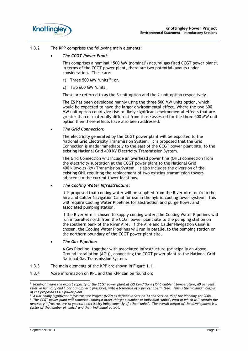
1.3.2 The KPP comprises the following main elements:
The CCGT Power Plant:
This comprises a nominal 1500 MW (nominal1) natural gas fired CCGT power plant2. In terms of the CCGT power plant, there are two potential layouts under consideration. These are:
1) Three 500 MW ‘units3’; or,
2) Two 600 MW ‘units.
These are referred to as the 3-unit option and the 2-unit option respectively.
The ES has been developed mainly using the three 500 MW units option, which would be expected to have the larger environmental effect. Where the two 600 MW unit option could give rise to likely significant environmental effects that are greater than or materially different from those assessed for the three 500 MW unit option then these effects have also been addressed.
The Grid Connection:
The electricity generated by the CCGT power plant will be exported to the National Grid Electricity Transmission System. It is proposed that the Grid Connection is made immediately to the east of the CCGT power plant site, to the existing National Grid 400 kV Electricity Transmission System.
The Grid Connection will include an overhead power line (OHL) connection from the electricity substation at the CCGT power plant to the National Grid 400 kilovolts (kV) Transmission System. It also includes the diversion of the existing OHL requiring the replacement of two existing transmission towers adjacent to the current tower locations.
The Cooling Water Infrastructure:
It is proposed that cooling water will be supplied from the River Aire, or from the Aire and Calder Navigation Canal for use in the hybrid cooling tower system. This will require Cooling Water Pipelines for abstraction and purge flows, and associated pumping station.
If the River Aire is chosen to supply cooling water, the Cooling Water Pipelines will run in parallel north from the CCGT power plant site to the pumping station on the southern bank of the River Aire. If the Aire and Calder Navigation Canal is chosen, the Cooling Water Pipelines will run in parallel to the pumping station on the northern boundary of the CCGT power plant site.
The Gas Pipeline:
A Gas Pipeline, together with associated infrastructure (principally an Above Ground Installation (AGI)), connecting the CCGT power plant to the National Grid National Gas Transmission System.
1.3.3 The main elements of the KPP are shown in Figure 1.1.
1.3.4 More information on KPL and the KPP can be found on:
1 Nominal means the export capacity of the CCGT power plant at ISO Conditions (15°C ambient temperature, 60 per cent relative humidity and 1 bar atmospheric pressure), with a tolerance of 5 per cent permitted. This is the maximum output of the proposed CCGT power plant. 2 A Nationally Significant Infrastructure Project (NSIP) as defined in Section 14 and Section 15 of the Planning Act 2008. 3 The CCGT power plant will comprise (amongst other things) a number of individual ‘units’, each of which will contain the necessary infrastructure to generate electricity independently of other ‘units’. The overall output of the development is a factor of the number of ‘units’ and their individual output.

Knottingley Power Project Environmental Statement - Introductory Sections
September 2013 Page 13
http://www.knottingleypower.co.uk/
1.4 Planning Policy Context
National Planning Policy
Planning Act 20084
1.4.1 The Planning Act 2008 introduced a new planning regime in England and Wales. The overall objective was to improve the process for the development of major infrastructure projects, making it both faster and fairer. The Planning Act 2008 facilitated:
The introduction of a new system comprising DCOs for Nationally Significant Infrastructure Projects (NSIPs);
The provision of National Policy Statements (NPSs), relating to one or more categories of development referred to in the Planning Act 2008; and,
The establishment of the Infrastructure Planning Commission (IPC).
Localism Act 20115
1.4.2 The Localism Bill was introduced to Parliament on 13 December 2010, and was given Royal Assent on 15 November 2011 becoming an Act. The Localism Act aims to deliver decentralisation and shift power from the Government to Local Communities and Local Councils. In relation to major infrastructure projects / NSIPs, the Localism Act 2011 has (amongst other things):
Abolished the IPC, and returned powers for determining applications for DCO for NSIPs to the Secretary of State (SoS);
Given the SoS power to extend the regime so that certain other consents for development do not need to be sought separately;
Allowed the SoS to direct that a development is to be treated as requiring a DCO under the Planning Act 2008 before any application has been made; and,
Required Parliamentary approval of NPSs.
Summary of Requirements under National Planning Policy
1.4.3 As the KPP will have a generating capacity of up to 1500 MW (nominal), it will require a DCO under Section 31 of the Planning Act 2008. This is consistent with the thresholds within the Planning Act 2008 for NSIPs, which, for power plant, is a threshold of 50 MW.
1.4.4 The application for a DCO will be submitted to the Planning Inspectorate’s National Infrastructure Directorate (PINS). PINS will consider the application and make recommendations to the SoS for Energy and Climate Change, who will determine the application for DCO.
1.4.5 Furthermore, under the provisions of the Planning Act 2008 and Localism Act 2011, NPSs have been prepared and approved to inform the consideration of applications for DCO for NSIPs. Accordingly, the NPSs that have been used to inform the proposals for the KPP are:
EN-1 Overarching Energy NPS;
EN-2 Fossil Fuel Electricity Generating Infrastructure NPS;
4 http://www.legislation.gov.uk/ukpga/2008/29/contents 5 http://www.legislation.gov.uk/ukpga/2011/20/contents/enacted

Knottingley Power Project Environmental Statement - Introductory Sections
September 2013 Page 14
EN-4 Gas Supply Infrastructure and Gas and Oil Pipelines NPS; and,
EN-5 Electricity Networks Infrastructure NPS.
1.4.6 The Planning Act 2008 requires that decisions on applications for DCO must be made in accordance with the relevant NPSs, except to the extent that to do so would:
Lead to the UK being in breach of its international obligations;
Be in breach of any Statutory Duty that applies;
Be unlawful;
Result in adverse impacts from the development outweighing the benefits; or,
Be contrary to Regulations about how decisions are to be taken.
Overarching Energy National Policy Statement (NPS EN-1)
1.4.7 Part 4 of NPS EN-1 (Assessment Principles) “sets out certain general policies in accordance with which applications relating to energy infrastructure are to be decided that do not relate only to the need for new energy infrastructure or to particular physical impacts of its construction or operation” (Paragraph 4.1.1).
1.4.8 The relevant Assessment Principles (comprising the general policies) applicable to the KPP are detailed in Appendix A.1.
Local Planning Policy
1.4.9 The KPP lies within the administrative areas of Wakefield Metropolitan District Council (WMDC) and extents into the administrative area of Selby District Council (SDC) and North Yorkshire County Council (NYCC). Indeed, the CCGT power plant site is located within the administrative boundary of WMDC, and the boundary of SDC is 70 m to the north east. The boundary of NYCC is concurrent with the boundary of SDC.
1.4.10 A summary of the local planning policies of WMDC and SDC applicable to the KPP are detailed in Appendix A.2.
1.5 Development Consent Order / Overview of the Consenting Process
1.5.1 As noted above, as the KPP will have a generating capacity of up to 1500 MW (nominal), it will require a DCO under Section 31 of the Planning Act 2008.
1.5.2 In addition, the DCO will remove the need for the applicant to apply for separate powers and consents under the following existing regimes:
Notice under Section 14 (1) of the Energy Act 1976;
Consents under Section 36 and Section 37 of the Electricity Act 1989;
Orders under the Harbours Act 1964; and,
Planning Permission, Listed Building Consent, Conservation Area Consent and Scheduled Monument Consent under the Town and County Planning Act 1990.
1.5.3 Furthermore, under Section 115(2) of the Planning Act 2008, a DCO may be applied for, and granted, in relation to an NSIP along with other development that relates to the NSIP known as “associated development”. In this regard, Guidance published by the Department of Communities and Local Government (DCLG)6 on 8 September 2009 describes "associated development" as development that "is actually an integral part of the NSIP", although it may be physically separate from it. PINS can only consider
6 Guidance on Associated Development: Applications to the Infrastructure Planning Commission. Department for
Communities and Local Government, September 2009.

Knottingley Power Project Environmental Statement - Introductory Sections
September 2013 Page 15
“associated development” in conjunction with an application for a DCO for an NSIP and will have no power to consider a separate application unless it is an application for a DCO for a NSIP in its own right. In this regard, PINS have expressed a preference for a single application to cover as much of the proposals as possible.
1.5.4 Further information on the DCO / consenting process is provided in Section 3 (Consenting Process / Environmental Impact Assessment Process).
1.6 Environmental Impact Assessment Process
1.6.1 Applications for development which are subject to the European Union (EU) Environmental Impact Assessment (EIA) Directive (Directive 2011/92/EU) on the assessment of certain public and private projects on the environment) must be accompanied by an ES.
1.6.2 The EIA Directive seeks to ensure that across the EU decision making processes for developments that may have major affects on the environment have regard to the precautionary principle (i.e. the principle that: wherever possible, preventative action should be taken to avoid environmental damage; where this is not possible, environmental damage should be rectified at source; and, the polluter should pay).
1.6.3 Accordingly, the EIA Directive requires Member States to provide that the effects on the environment should be taken into account at the earliest possible stages in the technical planning and decision making processes for such developments.
1.6.4 The EIA Directive also seeks to ensure that the decision making process enables the public to express opinions and concerns, and that the decision maker takes these into account in order to ensure an accountable and transparent decision making process, whilst also promoting public awareness of environmental issues.
1.6.5 In order to achieve these objectives, the EIA Directive prescribes a process through which consent for public and private projects / developments which are likely to have significant effects on the environment are granted only after an assessment of the likely significant effects has taken place. That assessment should be conducted on the basis of the appropriate information provided by the developer (i.e. provided in the ES) which may be supplemented by the authorities and by the public likely to be concerned by the project / development.
1.6.6 For the purposes of applications for DCO under the Planning Act 2008, the EIA Directive is transposed into United Kingdom (UK) Legislation via the Infrastructure Planning (Environmental Impact Assessment) Regulations 2009 (the 2009 EIA Regulations), as amended. Developments listed in Schedule 1 are mandatory EIA developments. Developments listed in Schedule 2 may be considered EIA developments if they are likely to have significant effects on the environment.
1.6.7 Schedule 1 and Schedule 2 of the 2009 EIA Regulations includes the following which are applicable to the KPP:
Schedule 1:
“2(a): Thermal power stations and other combustion installations with a heat output of 300 MW or more”; and,
“16: Pipelines for the transport of gas, oil or chemicals with a diameter of more than 800 millimetres and a length of more than 40 [kilometres] km”.
Schedule 2:
“3(a): Industrial installations for the production of electricity, steam and hot water (projects not included in Schedule 1)”;
Knottingley Power Project Environmental Statement - Introductory Sections
September 2013 Page 16
“3(b): Industrial installations for carrying gas, steam and hot water; transmission of electrical energy by overhead cables (projects not included in Schedule 1)”; and,
“10 (k): Oil and gas pipeline installations (unless included in Schedule 1)”.
1.6.8 The KPP falls within the definition of Schedule 1 (i.e. falls under 2(a) as it represents a thermal power station with a heat output of 300 MW or more) and is therefore a mandatory EIA development.
1.6.9 Accordingly, based on the requirement of the 2009 EIA Regulations, an ES has been prepared to accompany the KPP application for a DCO.
1.6.10 Further information on the environmental impact assessment process is provided in Section 3 (Consenting Process / Environmental Impact Assessment Process).
Environmental Statement
1.6.11 The ES should describe the aspects of the environment likely to be significantly affected by the project / development considering, in particular, effects on: human beings; flora and fauna; soil; water; air; climate; the landscape; material assets; cultural heritage; and, the interactions between them.
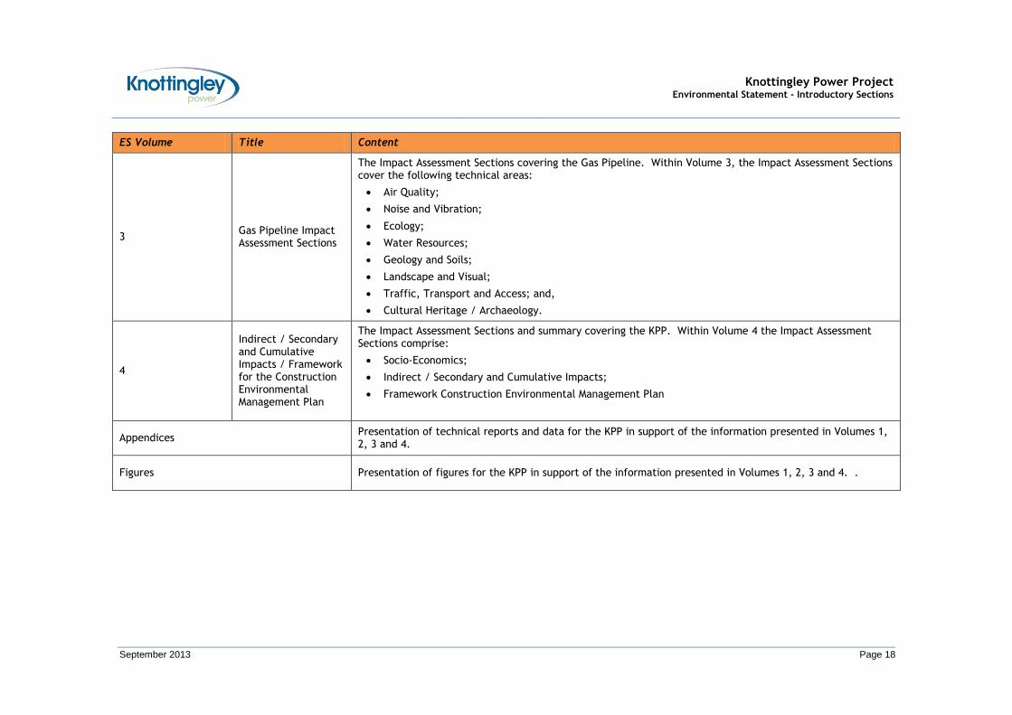
1.6.12 Accordingly, the structure of the ES for the KPP (in relation to the main elements) is set out in Table 1.2.
1.6.13 Further information on the Environmental Statement is provided in Section 3 (Consenting Process / Environmental Impact Assessment Process).

Knottingley Power Project Environmental Statement - Introductory Sections
September 2013 Page 17
TABLE 1.2: STRUCTURE OF THE ENVIRONMENTAL STATEMENT
ES Volume Title Content
Non Technical Summary (NTS)
An NTS of the information presented in the ES, in language that can be understood by Non-Specialist Consultees and the general public.
1 Introductory Sections
The Introductory Sections setting out the proposals for the KPP. Within Volume 1, the following introductory information will be provided:
Introduction;
Rationale for Development;
Consenting Process / EIA Process;
Environmental Scoping;
Alternatives; and,
Description of the Development.
2
CCGT Power Plant Site / Grid Connection / Cooling Water Infrastructure Impact Assessment Sections
The Impact Assessment Sections covering the CCGT Power Plant site, Grid Connection and Cooling Water Infrastructure. Within Volume 2, the Impact Assessment Sections cover the following technical areas:
Air Quality;
Noise and Vibration;
Terrestrial Ecology;
Aquatic Ecology;
Water Resources,
Geology and Soils;
Landscape and Visual;
Waste Management
Wastes Management;
Traffic, Transport and Access ; and,
Cultural Heritage.
Knottingley Power Project Environmental Statement - Introductory Sections
September 2013 Page 18
ES Volume Title Content
3 Gas Pipeline Impact Assessment Sections
The Impact Assessment Sections covering the Gas Pipeline. Within Volume 3, the Impact Assessment Sections cover the following technical areas:
Air Quality;
Noise and Vibration;
Ecology;
Water Resources;
Geology and Soils;
Landscape and Visual;
Traffic, Transport and Access; and,
Cultural Heritage / Archaeology.
4
Indirect / Secondary and Cumulative Impacts / Framework for the Construction Environmental Management Plan
The Impact Assessment Sections and summary covering the KPP. Within Volume 4 the Impact Assessment Sections comprise:
Socio-Economics;
Indirect / Secondary and Cumulative Impacts;
Framework Construction Environmental Management Plan
Appendices Presentation of technical reports and data for the KPP in support of the information presented in Volumes 1, 2, 3 and 4.
Figures Presentation of figures for the KPP in support of the information presented in Volumes 1, 2, 3 and 4. .
Knottingley Power Project Environmental Statement - Introductory Sections
September 2013 Page 19
SECTION 2
RATIONALE FOR DEVELOPMENT


Knottingley Power Project Environmental Statement - Introductory Sections
September 2013 Page 21
2 RATIONALE FOR DEVELOPMENT
2.1 Introduction
2.1.1 This Section provides the background to and provides the thought process for the Knottingley Power Project.
2.1.2 The majority of the discussion in this Section is taken from the Overarching NPS for Energy (EN-1) (NPS EN-1) (June 2011) which sets out national policy for NSIPs covered by the Planning Act 2008.
2.2 Background
2.2.1 Within NPS EN-1 it states (at paragraph 3.2.1) that:
“Energy underpins almost every aspect of our way of life. It enables us to heat and light our homes; to produce and transport food; to travel to work, around the country and the world. Our businesses and jobs rely on the use of energy. Energy is essential for the critical services we rely on – from hospitals to traffic lights and cash machines. It is difficult to overestimate the extent to which our quality of life is dependent on adequate energy supplies”.
2.2.2 NPS EN-1 goes on to say (at paragraph 3.3.1) that:
“Electricity meets a significant proportion of our overall energy needs and our reliance on it is likely to increase as we move towards our 2050 goals”.
2.2.3 Accordingly, the key reasons why the Government believes there is an urgent need for new electricity NSIPs are:
Meeting energy security and carbon reduction objectives;
The need to replace closing electricity generating capacity;
Future increases in electricity demand; and
The urgency of need for new electricity capacity.
2.2.4 These key reasons are further discussed in this Section, thus providing the rationale for development of the KPP.
2.3 Meeting Energy Security and Carbon Reduction Objectives
2.3.1 The Energy Markets Outlook Report (December 2009) states (at paragraph 4.3.1) that:
“As at the end of 2008, the UK as a whole had a total of 83.5 gigawatts (GW) of electricity generating capacity of various kinds … . In addition Great Britain had the capacity to import and export the equivalent of 2.5 GW form and to France and Ireland”.
2.3.2 The bulk of the 83.5 GW electricity generating capacity (totalling approximately 67 per cent) comprised fossil-fuelled power plant including: 28 per cent coal; 5 per cent oil; and, 34 per cent CCGT.
2.3.3 In meeting energy security, the Government needs to ensure that sufficient electricity generating capacity is available to meet maximum electricity demand. As such the total available electricity generating capacity includes a ‘safety margin’ (i.e. an amount of spare capacity) to accommodate unexpectedly high electricity demand and mitigate risks (i.e. such as unexpected power plant closures or extreme weather events).
2.3.4 The larger the difference between the electricity generating capacity and electricity demand (i.e. the larger the safety margin), the more resilient the system will be.

Knottingley Power Project Environmental Statement - Introductory Sections
September 2013 Page 22
2.3.5 Accordingly, in terms of meeting energy security, there are a number of associated benefits of having a diverse mix of electricity generating technologies / fuels. As an example, one benefit would be that there is no dependency on one type of generating technology or one type of fuel. Thus, in maintaining a diverse mix, different electricity generating technologies / fuels serve to complement one another. For example:
Nuclear power plant can provide proven low carbon base load electricity generation, helping to reduce the UK’s dependence on imported fossil-fuels;
Renewable power plant can also provide proven low carbon intermittent electricity generation, also helping to reduce the UK’s dependence on imported fossil-fuels; and
Some fossil-fuelled power plant (such as CCGT) can be brought on-line quickly when there is high demand and shut-down quickly when there is low demand, thus complementing base load electricity generation from nuclear and intermittent electricity generation from renewables.
2.3.6 In terms of carbon reduction objectives, NPS EN-1 states (at paragraph 3.3.5) that:
“The UK is choosing to largely decarbonise its power sector by adopting low carbon sources quickly. There are likely to be advantages to the UK of maintaining a diverse supply of energy sources so that we are not overly reliant on any one technology (avoiding dependency on a particular fuel or technology type). This is why the Government to bring forward as many new low carbon developments (renewables, nuclear and fossil fuel generation with [Carbon Capture and Storage] CCS) within the next 10 to 15 years to meet the twin challenge of energy security and climate change as we move towards 2050”.
2.3.7 Further to this, NPS EN-1 also states (at paragraph 3.3.10) that:
“As part of the UK’s need to diversify and decarbonise electricity generation, the Government is committed to increasing dramatically the amount of renewable generation capacity. In the short to medium term, much of this capacity is likely to be onshore and offshore wind, but increasingly it may include plant powered by the combustion of biomass and waste and the generation of electricity from wave and tidal power”.
2.3.8 However, it goes on to say (at paragraph 3.3.11) that:
“However, some renewable sources (such as wind, solar and tidal) are intermittent and cannot be adjusted to meet demand. As a result, the more renewable generating capacity we have the more generation capacity we will require overall, to provide back-up at times when the availability of intermittent renewable resources is low. If fossil fuel plant remains the most cost-effective means of providing such back-up, particularly at short notice, it is possible that even when the UK’s electricity supply is almost decarbonised we may still need fossil fuel power station for short periods when renewable output is too low to meet demand, for example when there is little wind”.
2.4 The Need to Replace Closing Electricity Generating Capacity
2.4.1 Directive 2001/80/EC on the limitation of emissions of certain pollutants into the air from large combustion plants (the Large Combustion Plant Directive (LCPD)) requires power plants to adhere to stringent air quality standards.
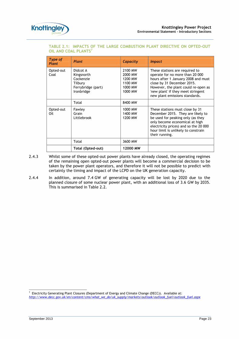
2.4.2 As a result, several power plants throughout the UK, totalling 12 GW, have opted-out of this obligation and, as such, are required to close by the end of 2015 or after 20 000 hours of operation after 1 January 2008, whichever is sooner. This is summarised in Table 2.1.
Knottingley Power Project Environmental Statement - Introductory Sections
September 2013 Page 23
TABLE 2.1: IMPACTS OF THE LARGE COMBUSTION PLANT DIRECTIVE ON OPTED-OUT OIL AND COAL PLANTS7
Type of Plant
Plant Capacity Impact
Opted-out Coal
Didcot A Kingsnorth Cockenzie Tilbury Ferrybridge (part) Ironbridge
2100 MW 2000 MW 1200 MW 1100 MW 1000 MW 1000 MW
These stations are required to operate for no more than 20 000 hours after 1 January 2008 and must close by 31 December 2015. However, the plant could re-open as 'new plant' if they meet stringent new plant emissions standards.
Total 8400 MW
Opted-out Oil
Fawley Grain Littlebrook
1000 MW 1400 MW 1200 MW
These stations must close by 31 December 2015. They are likely to be used for peaking only (as they only become economical at high electricity prices) and so the 20 000 hour limit is unlikely to constrain their running.
Total 3600 MW
Total (Opted-out) 12000 MW
2.4.3 Whilst some of these opted-out power plants have already closed, the operating regimes of the remaining open opted-out power plants will become a commercial decision to be taken by the power plant operators, and therefore it will not be possible to predict with certainty the timing and impact of the LCPD on the UK generation capacity.
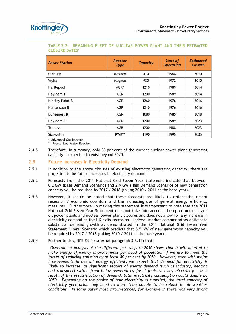
2.4.4 In addition, around 7.4 GW of generating capacity will be lost by 2020 due to the planned closure of some nuclear power plant, with an additional loss of 3.6 GW by 2035. This is summarised in Table 2.2.
7 Electricity Generating Plant Closures (Department of Energy and Climate Change (DECC)). Available at: http://www.decc.gov.uk/en/content/cms/what_we_do/uk_supply/markets/outlook/outlook_fuel/outlook_fuel.aspx
Knottingley Power Project Environmental Statement - Introductory Sections
September 2013 Page 24
TABLE 2.2: REMAINING FLEET OF NUCLEAR POWER PLANT AND THEIR ESTIMATED CLOSURE DATES7
Power Station Reactor
Type Capacity
Start of Operation
Estimated Closure
Oldbury Magnox 470 1968 2010
Wylfa Magnox 980 1972 2010
Hartlepool AGR* 1210 1989 2014
Heysham 1 AGR 1200 1989 2014
Hinkley Point B AGR 1260 1976 2016
Hunterston B AGR 1210 1976 2016
Dungeness B AGR 1080 1985 2018
Heysham 2 AGR 1200 1989 2023
Torness AGR 1200 1988 2023
Sizewell B PWR** 1190 1995 2035
* Advanced Gas Reactor ** Pressurised Water Reactor
2.4.5 Therefore, in summary, only 33 per cent of the current nuclear power plant generating capacity is expected to exist beyond 2020.
2.5 Future Increases in Electricity Demand
2.5.1 In addition to the above closures of existing electricity generating capacity, there are projected to be future increases in electricity demand.
2.5.2 Forecasts from the 2011 National Grid Seven Year Statement indicate that between 0.2 GW (Base Demand Scenario) and 2.9 GW (High Demand Scenario) of new generation capacity will be required by 2017 / 2018 (taking 2010 / 2011 as the base year).
2.5.3 However, it should be noted that these forecasts are likely to reflect the recent recession / economic downturn and the increasing use of general energy efficiency measures. Furthermore, in making this statement it is important to note that the 2011 National Grid Seven Year Statement does not take into account the opted-out coal and oil power plants and nuclear power plant closures and does not allow for any increase in electricity demand as the UK exits recession. Indeed, market commentators anticipate substantial demand growth as demonstrated in the 2011 National Grid Seven Year Statement ‘Users’ Scenario which predicts that 5.5 GW of new generation capacity will be required by 2017 / 2018 (taking 2010 / 2011 as the base year).
2.5.4 Further to this, NPS EN-1 states (at paragraph 3.3.14) that:
“Government analysis of the different pathways to 2050 shows that it will be vital to make energy efficiency improvements per head of population if we are to meet the target of reducing emission by at least 80 per cent by 2050. However, even with major improvements in overall energy efficient, we expect that demand for electricity is likely to increase, as significant sectors of energy demand (such as industry, heating and transport) switch from being powered by fossil fuels to using electricity. As a result of this electrification of demand, total electricity consumption could double by 2050. Depending on the choice of how electricity is supplied, the total capacity of electricity generation may need to more than double to be robust to all weather conditions. In some outer most circumstances, for example if there was very strong

Knottingley Power Project Environmental Statement - Introductory Sections
September 2013 Page 25
electrification of energy demand and a high level of dependence on intermittent electricity generation, then the capacity of electricity generation could need to triple. The Government therefore anticipates a substantial amount of new generation will be needed”.
2.6 The Urgency of Need for New Electricity Capacity
2.6.1 Based on the information above, the UK faces a need to replace 23 GW of generating capacity based on the closure of opted-out coal and oil power plants and nuclear power plant.
2.6.2 Considering this alongside the information from the 2011 National Grid Seven Year Statement, there is a clear need for between 23.2 GW (Base Demand Scenario) and 28.5 GW (‘Users’ Scenario) of new electricity generation in the UK, particularly in the years leading up to 2020. This is set to:
Aid the maintenance of a diverse, reliable, secure and strategically robust energy mix;
Replace the electricity generation capacity loss due to the opted-out coal and oil power plants and nuclear power plant closures; and
Cover the expected increases in electricity demands.
2.6.3 However, this is considered to be a very conservative estimate and NPS EN-1 (at Table 3.1) has provided additional indications of the possible scale of the future demand for new electricity generating capacity to 2025. These estimates range from 50 GW (low fossil fuel and carbon prices) to 59 GW (high fossil fuel and carbon prices). Indeed, NPS EN-1 states (at paragraph 3.3.23) that:
“To minimise risks to energy security and resilience, the Government therefore believes it is prudent to plan for a minimum need of 59 GW of new electricity capacity by 2025”.
2.7 Summary
2.7.1 NPS EN-1 states (at paragraph 3.6.8) that:
“A number of fossil fuel generating stations will have to close by the end of 2015. Although this capacity may be replaced by new nuclear and renewable generating capacity in due course, it is clear that there must be some fossil fuel generating capacity to provide back-up for when generation from intermittent renewable generating capacity is low and to help with the transition to low carbon electricity generation. It is important that such fossil fuel generating capacity should become low carbon, through development of CCS, in line with carbon reduction targets. Therefore there is a need for [Carbon Capture Ready] CCR fossil fuel generating stations”.
2.7.2 The KPP would be an appropriate candidate to fulfil this need.
2.7.3 Accordingly, and in agreement with NPS EN-1 (paragraph 3.1.3), it is considered that:
“The IPC [now PINS] should … assess all applications for development consent for the types of infrastructure covered by the energy NPSs on the basis that the Government has demonstrated that there is a need for those types of infrastructure”.
2.8 Benefits of the Development of the KPP
2.8.1 The development of the KPP provides the following benefits:
Up to 1500 MW of new generating capacity, enough to supply approximately two million homes, thus helping to ensure continuity of supply of electricity in the UK given the pending closure of old coal / oil fired and nuclear power plants;

Knottingley Power Project Environmental Statement - Introductory Sections
September 2013 Page 26
Potential to help reduce the UK’s carbon emissions as the CCGT power plant would emit approximately 50 per cent less carbon dioxide (CO2) than existing coal fired power plants;
Flexibility of power generation to enable electricity production to be increased or decreased as renewable generation fluctuates (e.g. when there is little wind);
Creation of up to 1100 construction jobs and 50 direct long term operational jobs on the CCGT power plant site, and spend with local firms and suppliers;
The CCGT power plant will have the potential to supply steam and / or hot water to the local area, which could reduce the overall amount of fuel needed to meet the equivalent energy requirements of standard heat-only generation; and,
The CCGT power plant will be designed to be CCR such that it will be able to be retrofitted with CCS if this becomes technically and economically feasible.

Knottingley Power Project Environmental Statement - Introductory Sections
September 2013 Page 27
SECTION 3
CONSENTING PROCESS / ENVIRONMENTAL IMPACT ASSESSMENT PROCESS


Knottingley Power Project Environmental Statement - Introductory Sections
September 2013 Page 29
3 CONSENTING PROCESS / ENVIRONMENTAL IMPACT ASSESSMENT PROCESS
3.1 Development Consent Order / Overview of the Consenting Process
3.1.1 As previously noted, as the KPP will have a generating capacity of up to 1500 MW (nominal), it will require a DCO under Section 31 of the Planning Act 2008.
3.1.2 The application for a DCO will be submitted to PINS. PINS will consider the application and make recommendations to the SoS for Energy and Climate Change, who will determine the application for DCO. Furthermore, PINS has expressed a preference for a single application to cover as much of the development proposals as possible.
Stages of the Consenting Process
3.1.3 The DCO process broadly follows five stages. These five stages are shown in Insert 3.1.

Knottingley Power Project Environmental Statement - Introductory Sections
September 2013 Page 30
INSERT 3.1: STAGES OF THE DCO PROCESS
Pre-Application
Project development and pre-application consultation
Completed
Acceptance by PINS
Period for PINS to decide whether an application can be accepted as valid.
MAXIMUM OF 28 DAYS
Pre-Examination
Applicant informs relevant parties of accepted application and deadline for initial comments to PINS.
Appointment of Examining Authority by PINS Chair to carry out initial assessment and hold preliminary meeting with promoter and other parties.
Procedure and timetable set for examination, including representations
ESTIMATED 3 MONTHS
Examination
Examination, including written representations and possible hearings.
Applicant and other parties engaged in process.
MAXIMUM 6 MONTHS
Recommendation by PINS
Following the examination, there will be a recommendation by PINS to the SoS for Energy and
Climate Change.
3 MONTHS
Decision
The SoS for Energy and Climate Change has three months to issue decision with reasons.
3 MONTHS
Knottingley Power Project Environmental Statement - Introductory Sections
September 2013 Page 31
Pre-Application
3.1.4 The pre-application stage of the consenting process involves the development of the project proposals, from inception through to the completion of the EIA / consultation process, and the preparation of the draft DCO and associated documents.
3.1.5 Indeed, under the Planning Act 2008, during the pre-application stage, applicants are required to consult. PINS can refuse to accept an application for a DCO if they believe that consultation at the pre-application stage has not been conducted properly.
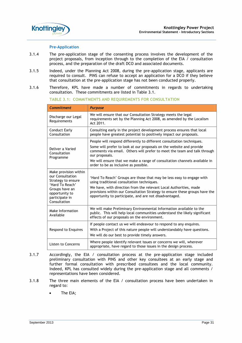
3.1.6 Therefore, KPL have made a number of commitments in regards to undertaking consultation. These commitments are listed in Table 3.1.
TABLE 3.1: COMMITMENTS AND REQUIREMENTS FOR CONSULTATION
Commitment Purpose
Discharge our Legal Requirements
We will ensure that our Consultation Strategy meets the legal requirements set by the Planning Act 2008, as amended by the Localism Act 2011.
Conduct Early Consultation
Consulting early in the project development process ensures that local people have greatest potential to positively impact our proposals.
Deliver a Varied Consultation Programme
People will respond differently to different consultation techniques.
Some will prefer to look at our proposals on the website and provide comments via email. Others will prefer to meet the team and talk through our proposals.
We will ensure that we make a range of consultation channels available in order to be as inclusive as possible.
Make provision within our Consultation Strategy to ensure ‘Hard To Reach’ Groups have an opportunity to participate in Consultation
‘Hard To Reach’ Groups are those that may be less easy to engage with using traditional consultation techniques.
We have, with direction from the relevant Local Authorities, made provisions within our Consultation Strategy to ensure these groups have the opportunity to participate, and are not disadvantaged.
Make Information Available
We will make Preliminary Environmental Information available to the public. This will help local communities understand the likely significant effects of our proposals on the environment.
Respond to Enquires
If people contact us we will endeavour to respond to any enquires.
With a Project of this nature people will understandably have questions.
We will do our best to provide timely answers.
Listen to Concerns Where people identify relevant issues or concerns we will, wherever appropriate, have regard to those issues in the design process.
3.1.7 Accordingly, the EIA / consultation process at the pre-application stage included preliminary consultation with PINS and other key consultees at an early stage and further formal consultation with prescribed consultees and the local community. Indeed, KPL has consulted widely during the pre-application stage and all comments / representations have been considered.
3.1.8 The three main elements of the EIA / consultation process have been undertaken in regard to:
The EIA;

Knottingley Power Project Environmental Statement - Introductory Sections
September 2013 Page 32
Section 42 to Section 46; and,
Section 47 (the local community).
Consultation in regard to the Environmental Impact Assessment
3.1.9 An important part of the consenting process is establishing the parameters for the project upon which the EIA and consultation should be based. It is also important to establish the need for EIA.
3.1.10 The mechanism for doing this is within Regulation 6 of the 2009 EIA Regulations. It is a requirement of Regulation 6 to either request a screening opinion or inform PINS that a project is an EIA development.
3.1.11 In April 2012, KPL submitted a notification to PINS under Regulation 6 (ii) of the 2009 EIA Regulations that the Knottingley Power Project was an EIA development and therefore would submit an ES with its application for a DCO.
3.1.12 Subsequent to submitting the notification under Regulation 6 (ii), in May 2012, KPL submitted an Environmental Scoping Report (ESR) to PINS. The ESR sought a formal ‘Scoping Opinion’ from PINS with respect to the information to be included within the ES and the methodologies to be used. The ESR is available to view at:
http://infrastructure.planningportal.gov.uk/projects/yorkshire-and-the-humber/knottingley-power-project/?ipcsection=folder
3.1.13 In response to the ESR, in June 2012, PINS issued their Environmental Scoping Opinion informing KPL (and KPL’s technical consultants) of the issues that PINS and prescribed consultees considered should be addressed by the EIA process. The PINS Environmental Scoping Opinion is available to view at:
http://infrastructure.planningportal.gov.uk/projects/yorkshire-and-the-humber/knottingley-power-project/?ipcsection=folder.
3.1.14 Further information on the PINS Environmental Scoping Opinion is provided in Section 4 (Environmental Scoping).
Consultation in regard to Section 42 to Section 46
3.1.15 Under Sections 42 to 44 of the Planning Act 2008, applicants must consult the following groups about the proposals for the development for at least 28 days:
Such persons as may be prescribed via the Infrastructure Planning (Applications: Prescribed Forms and Procedures) Regulations 2009;
The local authority within which the NSIP will be located as well as bordering local authorities; and,
Persons described in Section 44 of the Planning Act 2008, which essentially relates to:
o Land owners;
o Those with an interest in the land; or,
o Those whose land may be affected by the project.
3.1.16 However, it should be noted that this list does not mean that other parties should not be consulted. It merely identifies certain parties that an applicant shall consult before they submit an application for a DCO. In terms of the KPP, KPL consulted with PINS on the list of Section 42 consultees.
Knottingley Power Project Environmental Statement - Introductory Sections
September 2013 Page 33
3.1.17 Under Section 46 of the Planning Act 2008, all consultation material must be submitted to the PINS prior to commencing consultation. Accordingly, in March 2012, prior to the commencing consultation, KPL submitted a notification under Section 46 of the Planning Act 2008 (‘Duty to inform the Commission of Proposed Application’), together with the information to be supplied to the Section 42 consultees.
3.1.18 Once the notification under Section 46 had been accepted by PINS, this triggered the start of the formal Section 42 consultation.
Consultation in regard to Section 47
3.1.19 An additional significant component of the pre-application stage is the duty to consult the local community under Section 47 of Planning Act 2008. Accordingly, under Section 47 the applicant must draw up a statement explaining how it intends to carry out consultation with the local community. Before drawing up the statement, called a Statement of Community Consultation (SoCC), the applicant must consult the relevant local authority (or local authorities if the land needed for the project crosses local authority boundaries) about what the SoCC should say. The local authority (or local authorities) then has 28 days to reply.
3.1.20 Further to this, also under Section 47, the applicant must:
In preparing the SoCC, have regard to any responses from the local authority (or local authorities) about the SoCC;
Having prepared the SoCC, publish the SoCC in a newspaper circulating within the area the applicant wants to develop, and in such other manner as may be prescribed; and,
Carry out the consultation as laid out in the SoCC.
3.1.21 In February 2012, KPL submitted its draft SoCC to WMDC, SDC and NYCC. In response, the councils provided positive and constructive comments which were acted upon. Subsequently, in May 2012, KPL published the SoCC in a local newspaper. The SoCC was also available on the KPP website, at:
http://www.knottingleypower.co.uk/wp-content/uploads/2011/01/Final_Issue_KNOW_POWER_SOCC.pdf
3.1.22 In line with the SoCC, under Section 47 of the Planning Act 2008, consultation on the KPP with the local community comprised two key stages:
Stage 1 - Initial Consultation (May 2012)
Stage 1 provided initial information on: the proposals for the KPP; site opportunities and constraints; alternative technologies considered; and, possible impacts / proposed mitigation.
Stage 2: Preferred Proposals and Material Changes (November 2012)
Stage 2 provided comprehensive information on the preferred proposals for the KPP.
Stage 1 – Initial Consultation
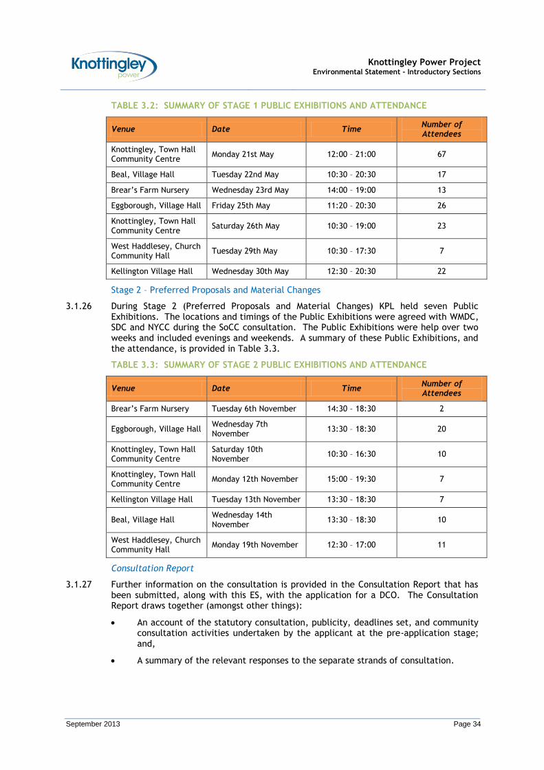
3.1.23 During Stage 1 (Initial Consultations) KPL held seven Public Exhibitions. The locations and timings of the Public Exhibitions were agreed with WMDC, SDC and NYCC during the SoCC consultation.
3.1.24 The Public Exhibitions were held over two weeks and included evenings and weekends.
3.1.25 A summary of these Public Exhibitions, and the attendance, is provided in Table 3.2.
Knottingley Power Project Environmental Statement - Introductory Sections
September 2013 Page 34
TABLE 3.2: SUMMARY OF STAGE 1 PUBLIC EXHIBITIONS AND ATTENDANCE
Venue Date Time Number of Attendees
Knottingley, Town Hall Community Centre
Monday 21st May 12:00 – 21:00 67
Beal, Village Hall Tuesday 22nd May 10:30 – 20:30 17
Brear’s Farm Nursery Wednesday 23rd May 14:00 – 19:00 13
Eggborough, Village Hall Friday 25th May 11:20 – 20:30 26
Knottingley, Town Hall Community Centre
Saturday 26th May 10:30 – 19:00 23
West Haddlesey, Church Community Hall
Tuesday 29th May 10:30 – 17:30 7
Kellington Village Hall Wednesday 30th May 12:30 – 20:30 22
Stage 2 – Preferred Proposals and Material Changes
3.1.26 During Stage 2 (Preferred Proposals and Material Changes) KPL held seven Public Exhibitions. The locations and timings of the Public Exhibitions were agreed with WMDC, SDC and NYCC during the SoCC consultation. The Public Exhibitions were help over two weeks and included evenings and weekends. A summary of these Public Exhibitions, and the attendance, is provided in Table 3.3.
TABLE 3.3: SUMMARY OF STAGE 2 PUBLIC EXHIBITIONS AND ATTENDANCE
Venue Date Time Number of Attendees
Brear’s Farm Nursery Tuesday 6th November 14:30 – 18:30 2
Eggborough, Village Hall Wednesday 7th November
13:30 – 18:30 20
Knottingley, Town Hall Community Centre
Saturday 10th November
10:30 – 16:30 10
Knottingley, Town Hall Community Centre
Monday 12th November 15:00 – 19:30 7
Kellington Village Hall Tuesday 13th November 13:30 – 18:30 7
Beal, Village Hall Wednesday 14th
November 13:30 – 18:30 10
West Haddlesey, Church Community Hall
Monday 19th November 12:30 – 17:00 11
Consultation Report
3.1.27 Further information on the consultation is provided in the Consultation Report that has been submitted, along with this ES, with the application for a DCO. The Consultation Report draws together (amongst other things):
An account of the statutory consultation, publicity, deadlines set, and community consultation activities undertaken by the applicant at the pre-application stage; and,
A summary of the relevant responses to the separate strands of consultation.
Knottingley Power Project Environmental Statement - Introductory Sections
September 2013 Page 35
3.1.28 Furthermore, the Consultation Report, along with the information provided in this ES, describes how consultation has influenced the proposals for the KPP.
3.1.29 Indeed, a key part of the draft DCO is the drafting of Requirements (previously referred to as Conditions). In this regard, KPL has engaged with the appropriate consultees to agree with them (and the planning authorities) the form of the proposed Requirements. This reflects another important part of the pre-application stage (i.e. to ensure that as many issues as possible are resolved prior to the submission of the application for a DCO).
Future Consultations
3.1.30 Consultation with interested parties has continued throughout the EIA process for the KPP through meetings and correspondence. Accordingly, throughout the determination process, KPL will continue to address any questions or concerns raised.
Acceptance / Pre-Examination / Examination
3.1.31 After an application for a DCO is submitted to PINS there is a period of review whereby PINS determines if the application meets the requirements of Planning Act 2008. This period is referred to as ‘Acceptance.’ PINS is required to provide a decision on application acceptance within 28 days of receiving the application.
3.1.32 Once an application is accepted, the planning authorities (WMDC, SDC and NYCC) may then prepare a Local Impact Report (LIR) on the proposals, and submit them to PINS.
3.1.33 PINS will appoint either a single Commissioner or panel of Commissioners to review the application and hold a hearing to consider it.
Decision
3.1.34 PINS will consider the application and make recommendations to the SoS for Energy and Climate Change, who will determine the application for DCO.
3.1.35 Accordingly, following the end of the examination process, PINS have 3 months to make its recommendation to the SoS for Energy and Climate Change. The report of recommendations will be made available on the relevant project page of the PINS website once a decision has been made.
3.1.36 Once the SoS for Energy and Climate Change has received the recommendation, he has a 3 month period to make a final decision. At the end of this three month period, the SoS for Energy and Climate Change will either grant a DCO or refuse it. A statement of reasons will accompany the decision which will be published on the relevant project page of the PINS website.
3.2 Environmental Impact Assessment Process
The EIA Process
3.2.1 As noted previously, applications for development which are subject to the EIA Directive must be accompanied by an ES. For the purposes of applications for DCO under the Planning Act 2008, the EIA Directive is transposed into UK Legislation via the 2009 EIA Regulations.
3.2.2 Accordingly, based on the requirement of the 2009 EIA Regulations, an ES has been prepared to accompany the application for DCO for the KPP.
Methodology for the Preparation of the ES
3.2.3 This ES covers the following impacts: direct, indirect, secondary or cumulative; short, medium or long term; permanent or temporary; and, positive or negative.

Knottingley Power Project Environmental Statement - Introductory Sections
September 2013 Page 36
3.2.4 The key steps employed in the preparation are presented in Insert 3.2, and reflect the staged approach being undertaken for the KPP. Indeed, the process depicted in Insert 3.2 is iterative, which means that many of the steps may need to be revisited in the event that new environmental information is discovered at a later step. In particular, and as noted above, consultation is an on-going activity, and responses from consultation are considered within the assessment and preparation.

Knottingley Power Project Environmental Statement - Introductory Sections
September 2013 Page 37
INSERT 3.2: KEY STEPS INVOLVED IN THE PREPARATION OF THE ENVIRONMENTAL STATEMENT

Knottingley Power Project Environmental Statement - Introductory Sections
September 2013 Page 38
3.2.5 In accordance with the 2009 EIA Regulations (as amended), the preparation of the ES has included the following key stages:
Identification of any Alternatives;
Discussions with Consultees on the key issues on which the EIA should focus and the methodologies which should be employed in terms of the key issues (the ESR);
Establishing baseline environmental conditions through desk-top research and site-surveys;
Consideration of assumed design and operation;
Identifying the potential environmental impacts (by means of the agreed methodologies);
Assessing the significance of cumulative environmental impacts;
Reporting the process, results and conclusions in an ES.
3.2.6 A brief description of these key stages for the KPP is provided in this Section.
Identification of Alternatives
3.2.7 The identification of alternatives is discussed in Section 5 (Alternatives).
Scoping of the ES
3.2.8 In May 2012, KPL submitted an ESR to PINS. The ESR sought a formal ‘Scoping Opinion’ from PINS with respect to the information to be included within the ES, and the environmental assessment methodologies and significance criteria to be used.
3.2.9 Further information on the PINS Environmental Scoping Opinion is provided in Section 4 (Environmental Scoping / Stakeholder Consultation).
Identification of Baseline Environmental Conditions
3.2.10 In undertaking an ES for any development it is important to identify the baseline environmental conditions at the site being considered. This allows the predicted effects of the development to be seen in the light of the existing environment and allows for better identification of the most appropriate mitigation (or monitoring), which could be employed to minimise impacts.
3.2.11 Accordingly, to establish the baseline environmental conditions for this ES, a wide range of data and sources has been used based on guidance, consultation responses, best practice and professional opinion (depending on the discipline). This has included (but has not been limited to):
Documentary information;
Field survey information; and,
Data from Statutory and Non-Statutory Consultees.
3.2.12 The identified environmental baseline conditions have then been used to assess the potential environmental impact of the KPP. This has included consideration of the potential environmental impacts against the proposed construction / operation / decommissioning dates.
3.2.13 The proposed construction / operation / decommissioning dates are as follows:
Start of Construction: 2015
Commissioning: 2017
Knottingley Power Project Environmental Statement - Introductory Sections
September 2013 Page 39
Commercial Operation: 2018
Decommissioning8: 2043
Description of the Proposed Development
3.2.14 A full description of the KPP is provided in Section 6 (Description of the Development).
Consideration of Assumed Design and Operation
3.2.15 In assessing the potential impacts, the ES has had regard to the assumed design and operation (i.e. embedded mitigation) associated with the KPP.
3.2.16 Generally speaking, in the hierarchy of mitigation, likely significant adverse impacts should in the first instance be avoided altogether, then reduced and finally offset through design and operational measures, or additional mitigation / monitoring measures. In terms of avoidance, the iterative nature of the EIA process has been used (and will continue to be used) to inform the final detailed design. Furthermore, in some cases, additional mitigation / monitoring measures have been suggested to help demonstrate that the KPP is able to operate in compliance with the criteria identified in this ES. This will be secured by way of Requirements in the DCO.
3.2.17 Information on the assumed design and operation is provided in Section 6 (Description of the Development) and within the respective Impact Sections of this ES.
3.2.18 Accordingly, the KPP has and will continue to be developed in such a way that reduction and, wherever possible, elimination of any associated adverse significant environmental impacts are an integral component of the overall design and operation.
Identification, Evaluation and Quantification of Potential Environmental Impacts
3.2.19 The identified impacts may be direct, indirect, secondary or cumulative. Within these categories they may be short, medium or long-term, permanent or temporary, and, positive or negative.
3.2.20 Direct impacts are changes to the environmental baseline arising directly from activities that form part of the development. For example, direct impacts may include localised increases in noise during construction. In terms of the KPP, direct impacts are assessed individually in the respective Impact Sections of this ES.
3.2.21 Indirect and secondary impacts are those which arise as a result of a direct / primary impact. A secondary impact is defined as changes which may be experienced at a point in space or time that is removed from both direct and indirect impacts. For example, deterioration of water quality in a watercourse due to an effluent discharge (which would be a direct impact) could have an indirect / secondary impact on aquatic biodiversity. Cumulative impacts occur when the environmental baseline / a receptor is subject to multiple impacts. In terms of the KPP, indirect / secondary and cumulative impacts are assessed in Section 26 (Indirect / Secondary and Cumulative Impacts).
3.2.22 The DCO application documents include Work Plans which show the gas and water pipelines route and the grid connection route (and related overhead line works) and the limits within which the route and works of these linear aspects of the project may deviate. The EIA has been sufficiently scoped to assess the likely significant environmental effects within the limits of deviation shown in the plans.
8 Assuming a 25 year design lifetime of the CCGT power plant. Alternatively, if market conditions and / or electricity supply constraints at that time indicate that it would be appropriate to extend the life of the CCGT power plant, then decommissioning may be deferred to a later date. In order to ensure continuing adequate operational conditions and performance, the CCGT power plant would be re-engineered and re-permitted as required, dependent upon the legislation, legislative guidelines and requirements at that time.

Knottingley Power Project Environmental Statement - Introductory Sections
September 2013 Page 40
Presentation of the Environmental Statement
3.2.23 The structure of the overall ES for the KPP is presented in Table 1.2.
3.3 Content of the Environmental Statement
3.3.1 Schedule 4 of the 2009 EIA Regulations (as amended) sets out the content required in the ES. In terms of the KPP, Table 3.4 presents this content required and indicates where these requirements are met in the different Sections of this ES.

Knottingley Power Project Environmental Statement - Introductory Sections
September 2013 Page 41
TABLE 3.4: INFORMATION REQUIRED IN AN ENVIRONMENTAL STATEMENT AS SET OUT IN SCHEDULE 4 OF THE INFRASTRUCTURE PLANNING (ENVIRONMENTAL IMPACT ASSESSMENT)
REGULATIONS 2009
Required Information Section of this ES
PART I
17
A description of the development, including in particular:
A description of the physical characteristics of the whole development and the land-use requirements during the construction and operation phases;
A description of the main characteristics of the production processes, for instance, nature and quantity of the materials used;
An estimate, by type and quantity, of expected residues and emissions (water, air and soil pollution, noise, vibration, light, heat, radiation, etc) resulting from the operation of the development.
Section 6
Impact Sections 7 to 25
18 An outline of the main alternatives studied by the applicant or appellant and an indication of the main reasons for his choice, taking into account the environmental effects.
Section 5
19
A description of the aspects of the environment likely to be significantly affected by the development, including, in particular, population, fauna, flora, soil, water, air, climatic factors, material assets (including the architectural and archaeological heritage), landscape and the inter-relationship between the above factors.
Impact Sections 7 to 25 /
Section 26
(Also see Table 3.5)
20
A description of the likely significant effects of the development on the environment, which should cover the direct effects and any indirect, secondary, cumulative, short, medium and long-term, permanent and temporary, positive and negative effects of the development, resulting from:
The existence of the development;
The use of natural resources;
The emissions of pollutants, the creation of nuisances and the elimination of waste, and
The description by the applicant of the forecasting methods used to assess the effects on the environment.
Impact Sections 7 to 25 /
Section 26
21 A description of the measures envisaged to prevent, reduce and where possible offset any significant adverse effects on the environment.
Impact Sections 7 to 25 /
Section 26
22 A non-technical summary of the information provided under paragraphs 1 to 5 of this Part.
Non-Technical Summary (NTS)
23 An indication of any difficulties (technical deficiencies of lack of know-how) encountered by the applicant in compiling the required information.
Impact Sections 7 to 25 /
Section 26
PART II
24 A description of the development comprising information on the site, design and size of the development.
Section 6
25 A description of the measures envisaged in order to avoid, reduce, and if possible remedy significant adverse impacts.
Impact Sections 7 to 25
26 The data required to identify and assess the main effects which the development is likely to have on the environment.
Impact Sections 7 to 25
27 An outline of the main alternatives studied by the applicant or appellant and an indication of the main reasons for his choice taking into account the environmental effects.
Section 5
28 A non-technical summary of the information provided under paragraphs 1 to 4 of this Part.
NTS
Knottingley Power Project Environmental Statement - Introductory Sections
September 2013 Page 42
Headings for the Impact Sections of the Environmental Statement
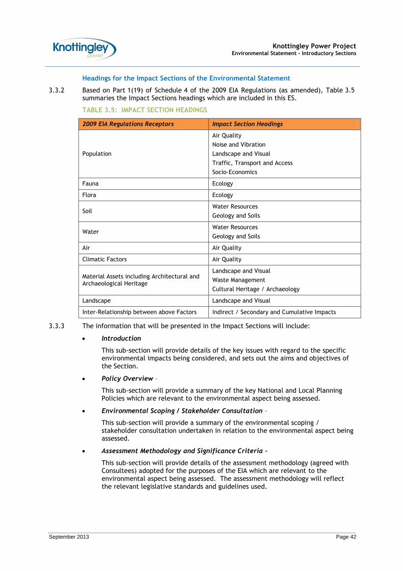
3.3.2 Based on Part 1(19) of Schedule 4 of the 2009 EIA Regulations (as amended), Table 3.5 summaries the Impact Sections headings which are included in this ES.
TABLE 3.5: IMPACT SECTION HEADINGS
2009 EIA Regulations Receptors Impact Section Headings
Population
Air Quality
Noise and Vibration
Landscape and Visual
Traffic, Transport and Access
Socio-Economics
Fauna Ecology
Flora Ecology
Soil Water Resources
Geology and Soils
Water Water Resources
Geology and Soils
Air Air Quality
Climatic Factors Air Quality
Material Assets including Architectural and Archaeological Heritage
Landscape and Visual
Waste Management
Cultural Heritage / Archaeology
Landscape Landscape and Visual
Inter-Relationship between above Factors Indirect / Secondary and Cumulative Impacts
3.3.3 The information that will be presented in the Impact Sections will include:
Introduction
This sub-section will provide details of the key issues with regard to the specific environmental impacts being considered, and sets out the aims and objectives of the Section.
Policy Overview –
This sub-section will provide a summary of the key National and Local Planning Policies which are relevant to the environmental aspect being assessed.
Environmental Scoping / Stakeholder Consultation –
This sub-section will provide a summary of the environmental scoping / stakeholder consultation undertaken in relation to the environmental aspect being assessed.
Assessment Methodology and Significance Criteria –
This sub-section will provide details of the assessment methodology (agreed with Consultees) adopted for the purposes of the EIA which are relevant to the environmental aspect being assessed. The assessment methodology will reflect the relevant legislative standards and guidelines used.

Knottingley Power Project Environmental Statement - Introductory Sections
September 2013 Page 43
This sub-section will also provide details of the significance criteria to be used to quantify the extent of the impact on the environmental aspect being considered.
Baseline Conditions and Receptors –
This sub-section will provide details of the environmental baseline conditions of the study area relevant to the environmental aspect being considered, and information on any sensitive receptors.
Assumed Design and Operation / Mitigation
This sub-section provides information on the assumed design and operation / mitigation associated with the KPP. This will be secured by way of Requirements in the DCO.
Potential Impacts / Impact Assessment –
This sub-section will discuss the findings of the impact assessment on the environmental aspect being considered, and will take in to consideration the development phases of the KPP, namely the construction / operation / decommissioning phases.
Potential impacts are identified as being: direct and indirect; long, medium or short term; and, positive, neutral or negative.
In undertaking this assessment both quantitative and qualitative evaluations are necessary, in varying degrees, depending on the nature of the impact being assessed.
The significance of the environmental impacts identified is addressed as appropriate with reference to the significance criteria established.
Description of Mitigation and Monitoring Measures –
This sub-section will provide a description of the mitigation measures. In some cases, additional mitigation / monitoring measures have been proposed to demonstrate that the KPP can be constructed and operated in compliance with the criteria identified in this ES. Additionally, enhancement measures to maximise any positive environmental impacts will be presented.
Assessment of Residual Impacts –
This sub-section identifies any residual / post-mitigation environmental impacts likely to be caused by the KPP.


Knottingley Power Project Environmental Statement - Introductory Sections
September 2013 Page 45
SECTION 4
ENVIRONMENTAL SCOPING


Knottingley Power Project Environmental Statement - Introductory Sections
September 2013 Page 47
4 ENVIRONMENTAL SCOPING
4.1 Introduction
4.1.1 Environmental scoping and stakeholder consultation are important components of the EIA process, allowing interested and affected parties and organisations to become involved in the planning and development process, and to ensure that their concerns, ideas and hopes are considered.
4.2 Environmental Scoping
4.2.1 In May 2012, KPL submitted an ESR to PINS. The ESR sought a formal ‘Scoping Opinion’ from PINS with respect to the information to be included within the ES, and the environmental assessment methodologies and significance criteria to be used. The ESR is available to view at:
http://infrastructure.planningportal.gov.uk/projects/yorkshire-and-the-humber/knottingley-power-project/?ipcsection=folder
4.2.2 In response to the ESR, in June 2012, PINS issued a scoping opinion informing KPL of the issues that PINS and prescribed consultees considered should be addressed by the EIA process. However, it is to be noted that the scoping opinion is not binding, and is intended to be more of a guide for use by the applicant in their preparation of the ES. The scoping opinion is available to view at:
http://infrastructure.planningportal.gov.uk/projects/yorkshire-and-the-humber/knottingley-power-project/?ipcsection=folder.
4.2.3 Table 4.1 provides a summary of the scoping comments, and the subsequent responses from KPL. Links to where this ES addresses the scoping comments are also provided. Relevant scoping comments and responses are summarised in each Impact Section.
4.2.4 Table 4.2 provides a summary of the scoping comments from other consultees, and subsequent responses from KPL. Similarly, links to where this ES addresses the scoping comments are also provided.

Knottingley Power Project Environmental Statement - Introductory Sections
September 2013 Page 48
TABLE 4.1: SUMMARY OF ENVIRONMENTAL SCOPING / STAKHOLDER CONSULTATION FROM THE SECRETARY OF STATE (GENERAL COMMENTS)9
Section / Topic Location in Scoping Opinion
Comments Response
Introduction Paragraph 1.13
“The ES submitted by the Applicant should demonstrate consideration of the points raised by the consultation bodies. It is recommended that a table is provided in the ES summarising the scoping responses from the consultation bodies and how they are, or are not, addressed in the ES”.
Table 4.1 provides a summary of the scoping comments, and the subsequent responses from KPL. Links to where this ES addresses the scoping comments are also provided. Relevant scoping comments and responses are summarised in each Impact Section.
Table 4.2 provides a summary of the scoping comments from other consultees, and subsequent responses from KPL. Similarly, links to where this ES addresses the scoping comments are also provided.
Description of the Application Site and Surrounding Area
Paragraph 2.54
“In addition to detailed baseline information to be provided within topic specific chapters of the ES, the SoS would expect the ES to include a section that summarises the site and surroundings. This would identify the context of the proposed development, any relevant designations and sensitive receptors. This section should identify land that could be directly or indirectly affected by the proposed development and any associated auxiliary facilities, landscaping areas and potential off site mitigation or compensation schemes”.
Section 6 provides a Description of the Development, including information on the site and its surroundings.
Further detailed information on the baseline is provided in each of the Impact Sections (7 to 25) of this ES.
Paragraph 2.55
“It is not always clear when references are made to the site whether it is to the area of the power plant only or the wider site contained within the red line boundary as shown on the location plan in Section 8 of the Scoping Report. In addition, references in the Scoping Report to the siting of elements of the proposed development are sometimes confusing for the reader”.
Section 6 provides a Description of the Development. This provides a description of the main elements of the KPP, namely: the CCGT power plant; the grid connection; the cooling water infrastructure; and, the gas pipeline.
The main elements of the KPP are shown in Figure 1.1.
9 In each of the Impact Sections, the Environmental Scoping Opinion from the Secretary of State, and subsequent actions taken, are summarised in relation to the specific environmental aspect being considered.
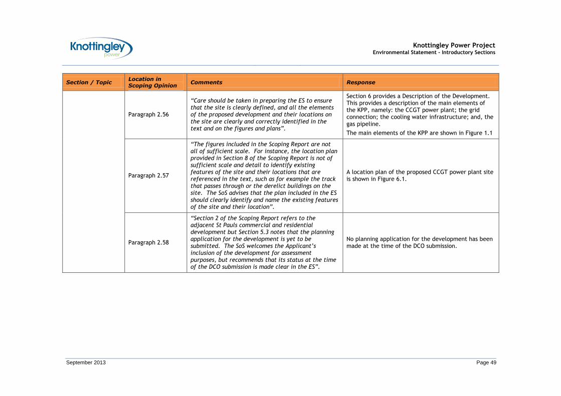
Knottingley Power Project Environmental Statement - Introductory Sections
September 2013 Page 49
Section / Topic Location in Scoping Opinion
Comments Response
Paragraph 2.56
“Care should be taken in preparing the ES to ensure that the site is clearly defined, and all the elements of the proposed development and their locations on the site are clearly and correctly identified in the text and on the figures and plans”.
Section 6 provides a Description of the Development. This provides a description of the main elements of the KPP, namely: the CCGT power plant; the grid connection; the cooling water infrastructure; and, the gas pipeline.
The main elements of the KPP are shown in Figure 1.1
Paragraph 2.57
“The figures included in the Scoping Report are not all of sufficient scale. For instance, the location plan provided in Section 8 of the Scoping Report is not of sufficient scale and detail to identify existing features of the site and their locations that are referenced in the text, such as for example the track that passes through or the derelict buildings on the site. The SoS advises that the plan included in the ES should clearly identify and name the existing features of the site and their location”.
A location plan of the proposed CCGT power plant site is shown in Figure 6.1.
Paragraph 2.58
“Section 2 of the Scoping Report refers to the adjacent St Pauls commercial and residential development but Section 5.3 notes that the planning application for the development is yet to be submitted. The SoS welcomes the Applicant’s inclusion of the development for assessment purposes, but recommends that its status at the time of the DCO submission is made clear in the ES”.
No planning application for the development has been made at the time of the DCO submission.
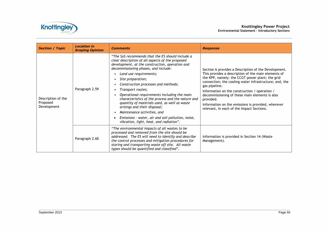
Knottingley Power Project Environmental Statement - Introductory Sections
September 2013 Page 50
Section / Topic Location in Scoping Opinion
Comments Response
Description of the Proposed Development
Paragraph 2.59
“The SoS recommends that the ES should include a clear description of all aspects of the proposed development, at the construction, operation and decommissioning phases, and include:
• Land use requirements;
• Site preparation;
• Construction processes and methods;
• Transport routes;
• Operational requirements including the main characteristics of the process and the nature and quantity of materials used, as well as waste arisings and their disposal;
• Maintenance activities, and
Emissions - water, air and soil pollution, noise, vibration, light, heat, and radiation”.
Section 6 provides a Description of the Development. This provides a description of the main elements of the KPP, namely: the CCGT power plant; the grid connection; the cooling water infrastructure; and, the gas pipeline.
Information on the construction / operation / decommissioning of these main elements is also provided.
Information on the emissions is provided, wherever relevant, in each of the Impact Sections.
Paragraph 2.60
“The environmental impacts of all wastes to be processed and removed from the site should be addressed. The ES will need to identify and describe the control processes and mitigation procedures for storing and transporting waste off site. All waste types should be quantified and classified”.
Information is provided in Section 14 (Waste Management).

Knottingley Power Project Environmental Statement - Introductory Sections
September 2013 Page 51
Section / Topic Location in Scoping Opinion
Comments Response
Paragraph 2.61
“The Scoping Report does not include any dimensions of the various elements of the power plant, e.g. the area of the buildings, or the stack height. Reference is made to further detail being included in the Indicative Layout figure although few dimensions are identified. The Report notes that pollutants will be emitted but provides no indication of the potential concentration, other than stating that they will be relatively low. It makes limited reference to a water vapour plume resulting from the hybrid cooling system being visible under certain climatic conditions but provides no further details. The likely dimensions and minimum burial depth of the gas pipeline are indicated in the Scoping Report and the SoS notes that they are yet to be finalised”.
Section 6 provides a Description of the Development. This provides a description of the main elements of the KPP, namely: the CCGT power plant; the grid connection; the cooling water infrastructure; and, the gas pipeline.
Information on the emissions is provided, wherever relevant, in each of the Impact Sections.
Paragraph 2.62
“The Applicant should be aware that the description of the development in the ES must be sufficiently certain to meet the requirements of paragraph 17, Part 1, Schedule 4 of the EIA Regulations, and there should therefore be more certainty by the time the ES is submitted with the DCO application”.
Section 6 provides a Description of the Development. This provides a description of the main elements of the KPP, namely: the CCGT power plant; the grid connection; the cooling water infrastructure; and, the gas pipeline.
Paragraph 2.63
“The Applicant’s attention is drawn to the requirements for carbon-capture readiness set out in section 4.7 of DECC’s ‘Overarching National Policy Statement for Energy (EN-1)’. The ES should where possible consider the potential effects associated with providing such abatement technology”.
A CCR Feasibility Study is provided as Appendix F.2.

Knottingley Power Project Environmental Statement - Introductory Sections
September 2013 Page 52
Section / Topic Location in Scoping Opinion
Comments Response
Paragraph 2.64
“The SoS notes that it is intended that the cooling water pipeline, the connection to the electricity network, and the gas pipeline will be included in the DCO application as associated development. However, this is not immediately clear from the initial descriptions of the proposed development in the Scoping Report. The Applicant should clearly define in the DCO application what elements of the proposed development are integral to the NSIP, and what are ‘associated development’ or ‘ancillary matters’ under the Planning Act 2008. Any proposed works and / or infrastructure required as associated development, or as an ancillary matter, (whether on or off-site) should be considered as part of an integrated approach to environmental assessment”.
Section 6 provides a Description of the Development. This provides a description of the main elements of the KPP, namely: the CCGT power plant; the grid connection; the cooling water infrastructure; and, the gas pipeline.
This ES considers the elements of the KPP.
Paragraph 2.65
“The terminology in the text and labelling of figures in the Scoping Report is not always consistent and contains errors. For instance, the ‘CCGT Power Plant Indicative Layout’ figure in Section 8 of the Scoping Report is titled differently on the Contents page and is variously titled in the text. The terminology used to describe the elements of the power plant identified in the key on the indicative layout figure is not the same as that used to describe the power generation process and in the Diagram 1 Schematic. The Scoping Report refers to the termination point for the gas pipeline at the power plant site and states that two possible options are under consideration but that it is yet to be determined. It is not clear whether any of the termination point infrastructure described is shown on the Indicative Layout figure in Section 8”.
The termination point will be within the Gas Compressor Building / Area. This is marked as Item 24 on both potential layouts for the CCGT power plant, provided in Figure 6.2 (for the 3-unit option) and Figure 6.3 (for the 2-unit option).

Knottingley Power Project Environmental Statement - Introductory Sections
September 2013 Page 53
Section / Topic Location in Scoping Opinion
Comments Response
Paragraph 2.66
“The Report refers to possible connection points for the gas pipeline to the Feeder 29 NTS pipeline at a section between the A6 and the A19, although the A6 does not appear to be shown on any plan and other references are to the A63. Section 3 of the Report refers to gas pipeline Routes 1, 2 and 2B, although all other references are to 1, 2, and 2A, including on the Route Options figure in Section 8. Features should be correctly identified, terminology should be consistently applied, and all figures and plans contained within the ES consistently titled and described in order to avoid confusion and provide clarity for the reader.”
The area of consideration is roughly bounded by the M62, A1 / A162, A63 and A19. This is shown on Insert 5.1. The reference to the A6 was incorrect.
Information on the alternative Gas Pipeline route is provided in Section 5.3.
Paragraph 2.67
“The figures in the body of the text and at the end of the scoping report are titled but many are not numbered and / or dated. For ease of cross-referencing, it must be ensured that all figures in the ES are referenced and dated.”
Noted.
Flexibility Paragraphs 2.68 and 2.69
“The SoS recognises that at this stage the design of the project may not be sufficiently advanced for the various components (e.g. stack height) to be accurately defined. The SoS recommends however that the Applicant should make every attempt to ensure that the description of the development (e.g. footprint, height, design, emissions) is sufficient to enable an assessment of the worst case impacts in the Environmental Statement. The scheme parameters will need to be clearly defined in the draft DCO and therefore in the accompanying ES. It is a matter for the Applicant, in preparing an ES, to consider whether it is possible to assess robustly a range of impacts resulting from a large number of undecided parameters”.
Section 6 provides a Description of the Development. This provides a description of the main elements of the KPP, namely: the CCGT power plant; the grid connection; the cooling water infrastructure; and, the gas pipeline.
Information on the impact assessment and the area covered / potential limitations are provided in each of the Impact Sections.
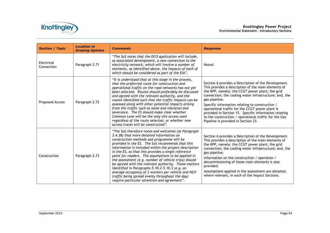
Knottingley Power Project Environmental Statement - Introductory Sections
September 2013 Page 54
Section / Topic Location in Scoping Opinion
Comments Response
Electrical Connection
Paragraph 2.71
“The SoS notes that the DCO application will include, as associated development, a new connection to the electricity network, which will involve a number of elements, as identified above, the impacts of each of which should be considered as part of the EIA”.
Noted.
Proposed Access Paragraph 2.72
“It is understood that at this stage in the process, that the preferred route for construction and operational traffic on the road networks has not yet been selected. Routes should preferably be discussed and agreed with the relevant authority, and the routes identified such that the traffic impacts can be assessed along with other potential impacts arising from the traffic such as noise and vibration and severance. The ES should make clear whether Common Lane will be the only site access used regardless of the route selected, or whether new access tracks will be constructed”.
Section 6 provides a Description of the Development. This provides a description of the main elements of the KPP, namely: the CCGT power plant; the grid connection; the cooling water infrastructure; and, the gas pipeline.
Specific information relating to construction / operational traffic for the CCGT power plant is provided in Section 15. Specific information relating to the construction / operational traffic for the Gas Pipeline is provided in Section 23.
Construction Paragraph 2.73
“The SoS therefore notes and welcomes (at Paragraph 3.4.38) that more detailed information on construction methods and programme will be provided in the ES. The SoS recommends that this information is included within the project description in the ES, so that this provides a single reference point for readers. The assumptions to be applied in the assessment (e.g. number of vehicle trips) should be agreed with the relevant authority. Those matters identified in Paragraphs 5.10.2-5.10.3 (e.g. an average occupancy of 2 workers per vehicle and HGV traffic being spread evenly throughout the day) require particular attention and agreement”.
Section 6 provides a Description of the Development. This provides a description of the main elements of the KPP, namely: the CCGT power plant; the grid connection; the cooling water infrastructure; and, the gas pipeline.
Information on the construction / operation / decommissioning of these main elements is also provided.
Assumptions applied in the assessment are detailed, where relevant, in each of the Impact Sections.

Knottingley Power Project Environmental Statement - Introductory Sections
September 2013 Page 55
Section / Topic Location in Scoping Opinion
Comments Response
Paragraph 2.74
“The SoS considers that information in the ES on construction of the pipeline (and other parts of the proposed development) should include:
• Phasing of programme;
• Construction methods and activities associated with each phase;
• Siting of construction compounds (including on and off site);
• Lighting equipment/requirements;
• Number and shift patterns of workers;
• Plant and equipment required; and number, movements and parking of construction vehicles (both HGVs and staff).”
Section 6 provides a Description of the Development. This provides a description of the main elements of the KPP, namely: the CCGT power plant; the grid connection; the cooling water infrastructure; and, the gas pipeline.
Information on the construction / operation / decommissioning of these main elements is also provided.
Information on the impact assessment and the associated assumptions are provided, where relevant, in each of the Impact Sections.
Paragraph 2.75
“There are scattered references in the Scoping Report to demolition works to buildings on the power plant site related to the former chemical works. The Applicant should ensure that all the elements of the proposed development are fully described and potentially significant impacts assessed in the ES”.
The preparation of the site, including demolition works, has been assessed in the Impact Sections where these works are pertinent.
Operation and Maintenance
Paragraphs 2.76 and 2.77
“The SoS notes and welcomes that additional details regarding the operation and maintenance of the project will be provided in the ES. The SoS recommends that this information should cover such matters as: the number of full / part-time jobs; the operational hours and if appropriate, shift patterns; the number and types of vehicle movements generated during the operational phase”.
Section 6 provides a Description of the Development. This provides a description of the main elements of the KPP, namely: the CCGT power plant; the grid connection; the cooling water infrastructure; and, the gas pipeline.
Information on the construction / operation / decommissioning of these main elements is also provided.
Information on the impact assessment and the associated assumptions are provided, where relevant, in each of the Impact Sections.

Knottingley Power Project Environmental Statement - Introductory Sections
September 2013 Page 56
Section / Topic Location in Scoping Opinion
Comments Response
Decommissioning Paragraphs 2.78 and 2.79
“Limited details only of the decommissioning of the gas pipeline are provided in the Scoping Report. The SoS acknowledges that the further into the future any assessment is made, the less reliance may be placed on the outcome. However, the purpose of such a long term assessment is to enable the decommissioning of the works to be taken into account in the design and use of materials such that structures can be taken down with the minimum of disruption. The process and methods of decommissioning should be considered and options presented in the ES. The SoS recommends that the EIA covers the life span of the proposed development, including construction, operation, and decommissioning.”
Section 6 provides a Description of the Development. This provides a description of the main elements of the KPP, namely: the CCGT power plant; the grid connection; the cooling water infrastructure; and, the gas pipeline.
Information on the construction / operation / decommissioning of these main elements is also provided.
Cumulative Impacts Paragraph 2.80
“Section 3.5 of the Scoping Report provides details of assessment of cumulative impacts and notes that the EIA will take into account other existing and planned developments in the area of the proposed site. Such developments are identified in Table 2 of the Report. However, the extent of the area to be included in the assessment is not defined and the distance of each of the identified developments from the proposed development is not stated in the text or the table. The Applicant will need to be satisfied that the assessment area is sufficiently broad to include all those developments which could contribute to a cumulative effect, and ensure that their locations are identified in the ES”.
Section 26 details the indirect / secondary and cumulative impact assessment.
Alternatives Paragraphs 2.81 and 2.82
“The Applicant must ensure that the ES outlines the main alternatives studied and provides an indication of the main reasons for the final selection. Advice on alternatives is provided in Appendix 3 of this Opinion”.
Section 5 provides information on Alternatives.
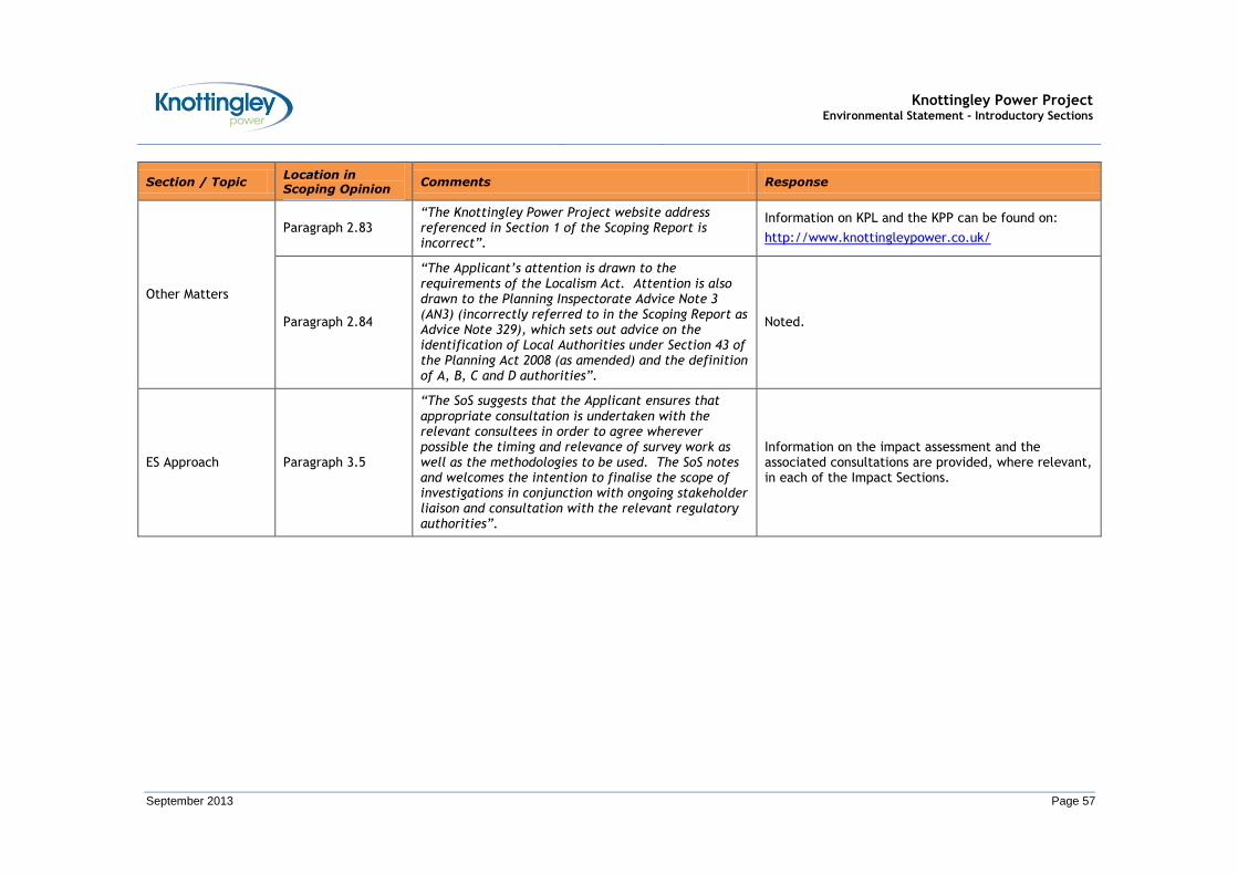
Knottingley Power Project Environmental Statement - Introductory Sections
September 2013 Page 57
Section / Topic Location in Scoping Opinion
Comments Response
Other Matters
Paragraph 2.83 “The Knottingley Power Project website address referenced in Section 1 of the Scoping Report is incorrect”.
Information on KPL and the KPP can be found on:
http://www.knottingleypower.co.uk/
Paragraph 2.84
“The Applicant’s attention is drawn to the requirements of the Localism Act. Attention is also drawn to the Planning Inspectorate Advice Note 3 (AN3) (incorrectly referred to in the Scoping Report as Advice Note 329), which sets out advice on the identification of Local Authorities under Section 43 of the Planning Act 2008 (as amended) and the definition of A, B, C and D authorities”.
Noted.
ES Approach Paragraph 3.5
“The SoS suggests that the Applicant ensures that appropriate consultation is undertaken with the relevant consultees in order to agree wherever possible the timing and relevance of survey work as well as the methodologies to be used. The SoS notes and welcomes the intention to finalise the scope of investigations in conjunction with ongoing stakeholder liaison and consultation with the relevant regulatory authorities”.
Information on the impact assessment and the associated consultations are provided, where relevant, in each of the Impact Sections.

Knottingley Power Project Environmental Statement - Introductory Sections
September 2013 Page 58
Section / Topic Location in Scoping Opinion
Comments Response
Paragraph 3.6
“The study areas are not defined in the Scoping Report for many of the topics, particularly in relation to the gas pipeline. The SoS recommends that the physical scope of the study areas should be identified under all the environmental topics and should be sufficiently robust in order to undertake the assessment. The extent of the study areas should be on the basis of recognised professional guidance, whenever such guidance is available. The study areas should also be agreed with the relevant consultees and, where this is not possible, this should be stated clearly in the ES and a reasoned justification given. The scope should also cover the breadth of the topic area and the temporal scope, and these aspects should be described and justified”.
Information on the impact assessment and the associated study areas are provided, where relevant, in each of the Impact Sections.
Paragraphs 3.7 and 3.8
“At this stage, the SoS does not agree that operational vibration should be excluded completely from consideration in the ES, as insufficient information has been provided in the Scoping Report by the Applicant to justify such an approach”.
Noted.
Topic Areas – the Power Plant
Paragraphs 3.13 to 3.88
In each of the impact sections for the CCGT power plant (Sections 7 to 16), the scoping opinion comments from the SoS, and subsequent responses, are summarised in relation to the specific environmental aspect being considered.
Topic Areas – the Gas Pipeline
Paragraphs 3.89 to 3.122
In each of the impact sections for the Gas Pipeline (Sections 17 to 24), the scoping opinion comments from the SoS, and subsequent respnses, are summarised in relation to the specific environmental aspect being considered.
Habitats Regulations Assessment
Paragraph 4.2
“The SoS notes that features of European sites could be affected by the proposed development. It is the Applicant’s responsibility to provide sufficient information to the Competent Authority (CA) to enable them to carry out a HRA if required. The Applicant should note that the CA is the SoS”.
Appendix I.12 presents a Habitats Regulations Assessment (HRA) – No Significant Effects Report.

Knottingley Power Project Environmental Statement - Introductory Sections
September 2013 Page 59
Section / Topic Location in Scoping Opinion
Comments Response
Paragraph 4.4
“The report to be submitted under Regulation 5(2)(g) of the APFP Regulations with the application must deal with two issues: the first is to enable a formal assessment by the CA of whether there is a likely significant effect; and the second, should it be required, is to enable the carrying out of an AA by the CA”.
Appendix I.12 presents a HRA – No Significant Effects Report.
SSSIs Paragraph 4.10
“If applicants consider it likely that notification may be necessary under s28(I), they are advised to resolve any issues with the NCB before the DCO application is submitted to the SoS. If, following assessment by applicants, it is considered that operations affecting the SSSI will not lead to damage of the special interest features, applicants should make this clear in the ES. The application documents submitted in accordance with Regulation 5(2)(l) could also provide this information. Applicants should seek to agree with NE the DCO requirements which will provide protection for the SSSI before the DCO application is submitted”.
Noted.
European Protected Species
Paragraph 4.12
“The SoS considers that there is potential for the presence of EPS within the study area for the proposed development. Where a potential risk to an EPS is identified and before making a decision to grant development consent the CA must, amongst other things, address the derogation tests in Regulation 53 of the Habitats Regulations. Therefore the Applicant may wish to provide information which will assist the decision maker to meet this duty. Where required the Applicant should, in consultation with NE, agree appropriate requirements to secure necessary mitigation”.
European Protected Species (EPS) are identified in Section 9 (Terrestrial Ecology). European Sites of Conservation Importance are assessed in Appendix I.12 which presents a HRA – No Significant Effects Report.

Knottingley Power Project Environmental Statement - Introductory Sections
September 2013 Page 60
Section / Topic Location in Scoping Opinion
Comments Response
Health Impact Assessment
Paragraph 4.14
“The SoS considers that it is a matter for the Applicant to decide whether or not to submit a stand-alone Health Impact Assessment (HIA). However, the Applicant should have regard to the responses received from the relevant consultees regarding health, and in particular to the comments from the Health and Safety Executive and Health Protection Agency (see Appendix 2).”
Appendix Y.1 presents a Health Impact Assessment (HIA) for the CCGT power plant. Appendix Y.2 presents a HIA for the Gas Pipeline.
Hazardous Substances Consent
Paragraph 4.17
“The decision-maker must consult with the HSE prior to making a decision to deem a HSC. The SoS therefore recommends that the Applicant consult with the HSE as well as seeking the views of the relevant authority who would normally be the Hazardous Substances Authority (if the Applicant were not seeking to deem consent), and any bodies that would normally be consulted under the Planning (Hazardous Substance) Regulations (as amended), e.g. fire services and affected landowners”.
Noted.
Authorisations, licences, permits
Paragraph 4.19
“The SoS recommends that the Applicant should state clearly what regulatory areas are addressed in the ES and that the Applicant should ensure that all relevant authorisations, licences, permits and consents that are necessary to enable operations to proceed are described in the ES. Also it should be clear that any likely significant effects of the proposed development which may be regulated by other statutory regimes have been properly taken into account in the ES.”
Section 6.13 details other consents / permits / licences which may be required for the KPP.

Knottingley Power Project Environmental Statement - Introductory Sections
September 2013 Page 61
TABLE 4.2: SUMMARY OF ENVIRONMENTAL SCOPING / STAKHOLDER CONSULTATION FROM OTHER STATUTORY CONSULTEES10
Statutory Consultee
Section / Topic Comment Response
Civil Aviation Authority (CAA)
Aerodromes
“In respect of any potential aerodrome related issue, I should highlight the need to check any safeguarding maps lodged with relevant planning authorities to identify any aerodrome specific safeguarding issues. Noting that aerodrome safeguarding responsibility rests in all cases with the relevant aerodrome operator / licensee, not the CAA, it is important that the developer engage direct with any relevant aerodromes”.
Information is provided in the Consultation Report
Aviation Warning Lighting
“Aviation Warning Lighting. Given the height of associated structures there is a likely need for aviation warning lighting”.
Aircraft warning lights will be installed on the stacks.
Gas Venting/ Flaring
“The documentation available does not appear to mention whether the development would vent or flare gas either routinely or as an emergency procedure such as to cause a danger to overlying aircraft. It is assumed that it would not. If that is not the case parties are invited to use myself as an appropriate point of contact for any further related discussion”.
Noted.
Aviation Promulgation
“There is a civil aviation requirement in the UK for all structures over 300 feet high to be charted on aviation maps. Should this development progress and the 300 feet height be breached, to achieve this charting requirement, developers will need to provide details of the development to the Defence Geographic Agency”.
The proposed stacks are to be up to 75 m high, and therefore do not need to be charted.
Military Aviation “For completeness, the Ministry of Defence position in regards to the proposed development and military aviation activity should be established”.
Information is provided in the Consultation Report
10 Responses contained in Environmental Scoping Opinion (Appendix 2 – Letters from Consultees)
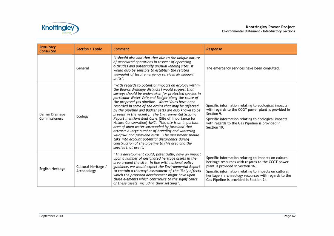
Knottingley Power Project Environmental Statement - Introductory Sections
September 2013 Page 62
Statutory Consultee
Section / Topic Comment Response
General
“I should also add that that due to the unique nature of associated operations in respect of operating altitudes and potentially unusual landing sites, it would also be sensible to establish the related viewpoint of local emergency services air support units”.
The emergency services have been consulted.
Danvm Drainage Commissioners
Ecology
“With regards to potential impacts on ecology within the Boards drainage districts I would suggest that surveys should be undertaken for protected species in particular Water Vole and Badger along the route of the proposed gas pipeline. Water Voles have been recorded in some of the drains that may be affected by the pipeline and Badger setts are also known to be present in the vicinity. The Environmental Scoping Report mentions Beal Carrs [Site of Importance for Nature Conservation] SINC. This site is an important area of open water surrounded by farmland that attracts a large number of breeding and wintering wildfowl and farmland birds. The assessment should take into account potential disturbance during construction of the pipeline to this area and the species that use it.”
Specific information relating to ecological impacts with regards to the CCGT power plant is provided in Section 9.
Specific information relating to ecological impacts with regards to the Gas Pipeline is provided in Section 19.
English Heritage Cultural Heritage / Archaeology
“This development could, potentially, have an impact upon a number of designated heritage assets in the area around the site. In line with national policy guidance, we would expect the Environmental Report to contain a thorough assessment of the likely effects which the proposed development might have upon those elements which contribute to the significance of these assets, including their settings”.
Specific information relating to impacts on cultural heritage resources with regards to the CCGT power plant is provided in Section 16.
Specific information relating to impacts on cultural heritage / archaeology resources with regards to the Gas Pipeline is provided in Section 24.
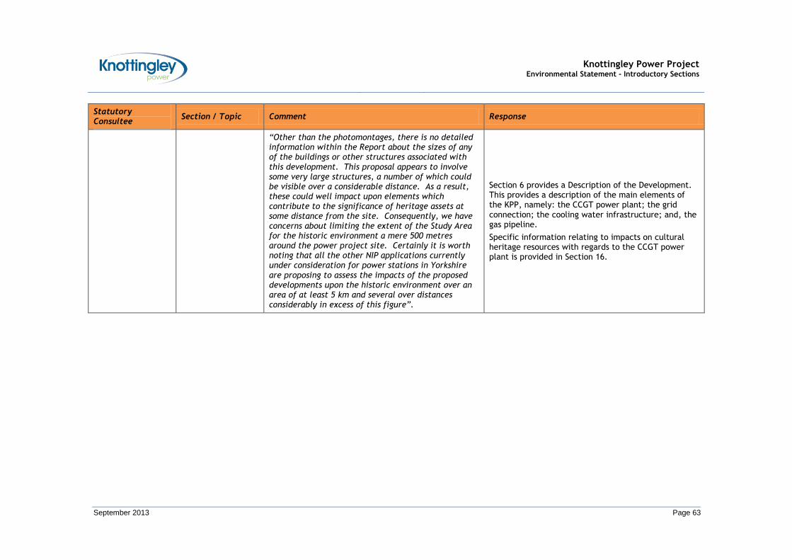
Knottingley Power Project Environmental Statement - Introductory Sections
September 2013 Page 63
Statutory Consultee
Section / Topic Comment Response
“Other than the photomontages, there is no detailed information within the Report about the sizes of any of the buildings or other structures associated with this development. This proposal appears to involve some very large structures, a number of which could be visible over a considerable distance. As a result, these could well impact upon elements which contribute to the significance of heritage assets at some distance from the site. Consequently, we have concerns about limiting the extent of the Study Area for the historic environment a mere 500 metres around the power project site. Certainly it is worth noting that all the other NIP applications currently under consideration for power stations in Yorkshire are proposing to assess the impacts of the proposed developments upon the historic environment over an area of at least 5 km and several over distances considerably in excess of this figure”.
Section 6 provides a Description of the Development. This provides a description of the main elements of the KPP, namely: the CCGT power plant; the grid connection; the cooling water infrastructure; and, the gas pipeline.
Specific information relating to impacts on cultural heritage resources with regards to the CCGT power plant is provided in Section 16.
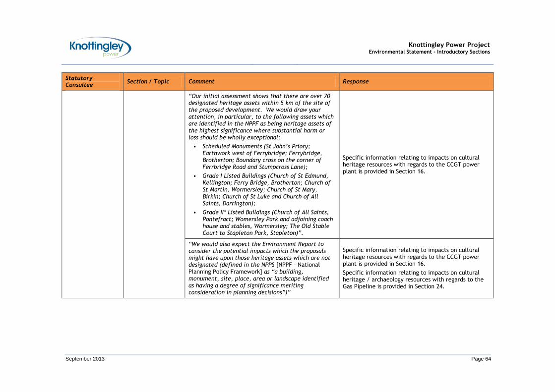
Knottingley Power Project Environmental Statement - Introductory Sections
September 2013 Page 64
Statutory Consultee
Section / Topic Comment Response
“Our initial assessment shows that there are over 70 designated heritage assets within 5 km of the site of the proposed development. We would draw your attention, in particular, to the following assets which are identified in the NPPF as being heritage assets of the highest significance where substantial harm or loss should be wholly exceptional:
• Scheduled Monuments (St John’s Priory; Earthwork west of Ferrybridge; Ferrybridge, Brotherton; Boundary cross on the corner of Ferrbridge Road and Stumpcross Lane);
• Grade I Listed Buildings (Church of St Edmund, Kellington; Ferry Bridge, Brotherton; Church of St Martin, Wormersley; Church of St Mary, Birkin; Church of St Luke and Church of All Saints, Darrington);
• Grade II* Listed Buildings (Church of All Saints, Pontefract; Womersley Park and adjoining coach house and stables, Wormersley; The Old Stable Court to Stapleton Park, Stapleton)”.
Specific information relating to impacts on cultural heritage resources with regards to the CCGT power plant is provided in Section 16.
“We would also expect the Environment Report to consider the potential impacts which the proposals might have upon those heritage assets which are not designated (defined in the NPPS [NPPF – National Planning Policy Framework] as “a building, monument, site, place, area or landscape identified as having a degree of significance meriting consideration in planning decisions”)”
Specific information relating to impacts on cultural heritage resources with regards to the CCGT power plant is provided in Section 16.
Specific information relating to impacts on cultural heritage / archaeology resources with regards to the Gas Pipeline is provided in Section 24.
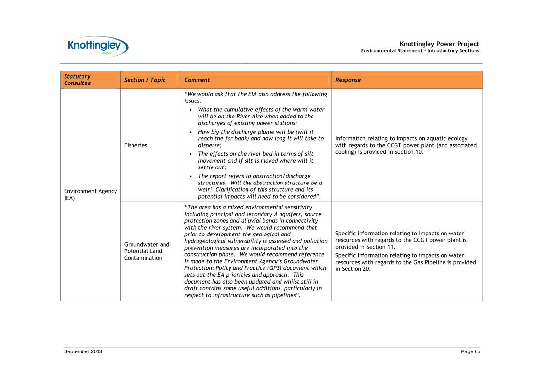
Knottingley Power Project Environmental Statement - Introductory Sections
September 2013 Page 65
Statutory Consultee
Section / Topic Comment Response
Environment Agency (EA)
Fisheries
“We would ask that the EIA also address the following issues:
• What the cumulative effects of the warm water will be on the River Aire when added to the discharges of existing power stations;
• How big the discharge plume will be (will it reach the far bank) and how long it will take to disperse;
• The effects on the river bed in terms of silt movement and if silt is moved where will it settle out;
• The report refers to abstraction/discharge structures. Will the abstraction structure be a weir? Clarification of this structure and its potential impacts will need to be considered”.
Information relating to impacts on aquatic ecology with regards to the CCGT power plant (and associated cooling) is provided in Section 10.
Groundwater and Potential Land Contamination
“The area has a mixed environmental sensitivity including principal and secondary A aquifers, source protection zones and alluvial bands in connectivity with the river system. We would recommend that prior to development the geological and hydrogeological vulnerability is assessed and pollution prevention measures are incorporated into the construction phase. We would recommend reference is made to the Environment Agency’s Groundwater Protection: Policy and Practice (GP3) document which sets out the EA priorities and approach. This document has also been updated and whilst still in draft contains some useful additions, particularly in respect to infrastructure such as pipelines”.
Specific information relating to impacts on water resources with regards to the CCGT power plant is provided in Section 11.
Specific information relating to impacts on water resources with regards to the Gas Pipeline is provided in Section 20.

Knottingley Power Project Environmental Statement - Introductory Sections
September 2013 Page 66
Statutory Consultee
Section / Topic Comment Response
“The proposed development site also has a mixed industrial history and is likely to be affected by land contamination. This contamination would need to be assessed in relation to the proposed development but also in respect to impacts on environmental receptors. A risk based remediation scheme is likely to be required. We consider these aspects merit consideration within the EIA”.
Specific information relating to impacts on geology and soils (including land contamination) with regards to the CCGT power plant is provided in Section 11.
Flood Risk
“The power station site lies within flood zone 2 as defined by the National Planning Policy Framework (NPPF) and Technical Guidance Note. The NPPF requires decision makers to steer new development to areas at the lowest probability of flooding by applying a flood risk 'Sequential Test'. We advise that the Sequential Test be carried out at an early stage of the application determination process”.
Appendix K.1 presents a Flood Risk Assessment (FRA) for the CCGT power plant
“The proposed power plant site lies in Flood Zone 2 whilst the proposed pipeline routes cross Flood Zones 1, 2, 3a and 3b. As stated in the Environmental Scoping Report the planning application should be supported by a site specific Flood Risk Assessment (FRA). The FRA should determine whether or not the development can be made safe from flooding, and remain safe for its perceived lifetime taking into account the possible effects of climate change. The construction phase in addition to the completed development should be assessed”.
Appendix K.1 presents a FRA for the CCGT power plant.
Section 20 presents a FRA for the Gas Pipeline.
River and Flood Defence Crossings
“The Environmental Scoping Report identifies several watercourse and river crossings. In addition to actual river crossings the potential routes also cross formal flood defences. Details of the proposed construction methods for these crossings should be provided”.
Section 6 provides a Description of the Development. This includes, at Table 6.4, the proposed Gas Pipeline Crossing Schedule and, at Section 6.11, information on construction / operation / decommissioning.

Knottingley Power Project Environmental Statement - Introductory Sections
September 2013 Page 67
Statutory Consultee
Section / Topic Comment Response
Water Quality
“The developer should have regard to the requirements of the Water Framework Directive. The Environmental Scoping Report makes no mention of this key piece of EU Legislation which now governs the water environment. The main aims of this piece of Legislation are to prevent deterioration in water quality and to achieve Good Ecological Status. Consideration should be given to the potential need for mitigation measures to prevent deterioration of watercourses and to prevent the development acting as a barrier to achieving good ecological status”.
“By virtue of the methods of laying transmission pipelines, there exists a great potential for pollution through runoff of exposed soils causing siltation and sedimentation of nearby watercourses. Any dewatering activities also posses the potential to cause similar damage by transferring suspended solids to land or water. This has been an issue with some previous pipeline developments. As a result, within the ES, detailed consideration should be given pollution prevention techniques to mitigate the risk to watercourses through sedimentation, augmented by a route plan which minimises the potential pathways for pollution”.
“This information could be presented in a draft construction method statement to be included within the ES, which would provide the Environment Agency greater clarity of the potential environmental risks through the construction phase and allow us to provide targeted guidance on necessary pollution prevention measures”.
Specific information with regards to the CCGT power plant is provided in Section 11.
Specific information with regards to the Gas Pipeline is provided in Section 20.
A proposed Framework for a Construction Environmental Management Plan (CEMP) is provided in Section 27.
Environmental Permitting and Other Regulation
“The applicant will be required to apply for an Environmental Permit (Environmental Permitting (England and Wales) Regulations 2010).
Section 6.13 details other consents / permits / licences which may be required for the KPP.

Knottingley Power Project Environmental Statement - Introductory Sections
September 2013 Page 68
Statutory Consultee
Section / Topic Comment Response
Consent for Works affecting Water Courses and / or Flood Defences
“Under the terms of the Water Resources Act 1991 and the Yorkshire Land Drainage Byelaws, the prior written consent of the Environment Agency is required for any proposed works or structures in, under, over or within 8 metres of the top of the bank of a 'Main River', or within 8 metres of any flood defence. The proposals identify potential crossings over the River Aire, designated as ‘Main River’”.
“From 6 April 2012, Section 23 of the Land Drainage Act 1991 (LDA 1991) has been amended by the Flood and Water Management Act (FWMA) 2010. This means that the regulatory powers on Ordinary Watercourses have been transferred from the Environment Agency to the Lead Local Flood Authority (LLFA). Therefore, all applications for consent for the erection of any culvert and / or any alteration likely to affect the flow in an Ordinary Watercourse must be made to the LLFA, or to the local Internal Drainage Board (IDB) where they exist”.
Section 6.13 details other consents / permits / licences which may be required for the KPP.
Health and Safety Executive (HSE)
Major Hazard Installations
“The proposed Knottingley Power Station falls within four of HSE’s consultation distances, and the development is adjacent to a further two consultation distances. Assuming that a planning application is submitted for a new 1500 MW CCGT power station, on the basis of a preliminary assessment it is unlikely that HSE would advise against the proposal. HSE may need to review its position on the basis of a fresh assessment of the data available when a formal application is referred to us”.
Noted.

Knottingley Power Project Environmental Statement - Introductory Sections
September 2013 Page 69
Statutory Consultee
Section / Topic Comment Response
“As the proposed development is within the Consultation Distance of several major hazard pipelines operated by National Grid Gas and Northern Gas Networks, the Applicant should consider contacting the pipeline operators. There are two particular reasons for this:
• The operator may have legal interest in the vicinity of the pipeline. They may restrict certain developments within a certain proximity of the pipeline.
• The standards to which the pipeline is designed and operated may restricted occupied buildings or major traffic routes within a certain proximity of the pipeline. Consequently there may be a need for the operator to modify the pipeline, or its operation, if the development proceeds.
It is the responsibility of the Applicant to ensure the latest pipeline information is used to form the basis of the scoping consultation”.
Information on techniques for crossing existing third party pipelines / services / utilities is provided in Section 6.11 (Flowchart 6.1 and Flowchart 6.2).
“The Environmental Scoping Report indicates that a new gas pipeline will be constructed to connect the power plant to the National Transmission System. The pipeline will be subject to the requirements under the Pipeline Safety Regulations (PSR) 1996. There is not sufficient information in the Scoping report to assess the application relative to a potential new Consultation Distance from the new gas pipeline”.
Information relating to the requirements under the PSR 1996 will be provided at the appropriate stage of development.

Knottingley Power Project Environmental Statement - Introductory Sections
September 2013 Page 70
Statutory Consultee
Section / Topic Comment Response
Hazardous Substances Consent
“Paragraph 5.10.7 of the Environmental Scoping Report provided an indication that the proposal will store and use hazardous substances e.g. diesel, industrial gases, solvents and water treatment chemicals, and therefore may require a new Hazardous Substances Consent [HSC]”.
Relevant consents will be sought by the applicant prior to bringing hazardous substances on site.
Section 6.13 details other consents / permits / licences which may be required for the KPP.
“Consideration should be given to the potential Carbon Capture and Storage operation ... as the process may also use hazardous substances”.
A CCR Feasibility Study is provided as Appendix F.2.
“The Applicant is required to determine the boundary of where the application of PSR 1996 Regulations of the new gas pipeline terminates and where the application of HSC applies”.
The boundary will be within the ‘Gas Compressor Building / Area’. This is marked as Item 24 on both potential layouts for the CCGT power plant, provided in Figure 6.2 (for the 3-unit option) and Figure 6.3 (for the 2-unit option).
Health Protection Agency (HPA)
General
“The HPA will only consider information contained or referenced in a separate section of the ES summarising the impact of the proposed development on public health: summarising risk assessments, proposed mitigation measures, and residual impacts. This section should summarise key information and conclusions relating to human health impacts contained in other sections of the application (e.g. in the separate sections dealing with: air quality, emissions to water, waste, contaminated land, etc) without undue duplication. Compliance with the requirements of National Policy Statements and relevant guidance and standards should be highlighted”.
Appendix Y.1 presents a HIA for the CCGT power plant.
Appendix Y.2 presents a HIA for the Gas Pipeline.
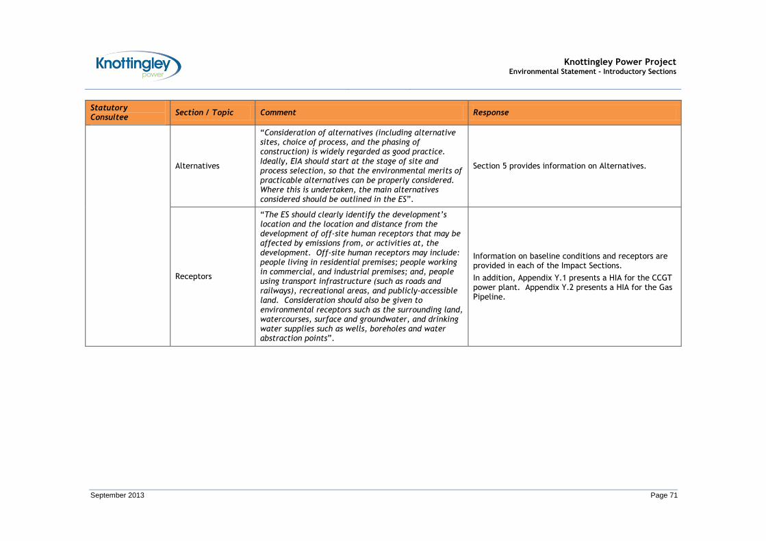
Knottingley Power Project Environmental Statement - Introductory Sections
September 2013 Page 71
Statutory Consultee
Section / Topic Comment Response
Alternatives
“Consideration of alternatives (including alternative sites, choice of process, and the phasing of construction) is widely regarded as good practice. Ideally, EIA should start at the stage of site and process selection, so that the environmental merits of practicable alternatives can be properly considered. Where this is undertaken, the main alternatives considered should be outlined in the ES”.
Section 5 provides information on Alternatives.
Receptors
“The ES should clearly identify the development’s location and the location and distance from the development of off-site human receptors that may be affected by emissions from, or activities at, the development. Off-site human receptors may include: people living in residential premises; people working in commercial, and industrial premises; and, people using transport infrastructure (such as roads and railways), recreational areas, and publicly-accessible land. Consideration should also be given to environmental receptors such as the surrounding land, watercourses, surface and groundwater, and drinking water supplies such as wells, boreholes and water abstraction points”.
Information on baseline conditions and receptors are provided in each of the Impact Sections.
In addition, Appendix Y.1 presents a HIA for the CCGT power plant. Appendix Y.2 presents a HIA for the Gas Pipeline.

Knottingley Power Project Environmental Statement - Introductory Sections
September 2013 Page 72
Statutory Consultee
Section / Topic Comment Response
Impact Assessment
“Any assessment of impacts arising from emissions due to construction and decommissioning should consider potential impacts on all receptors and describe monitoring and mitigation during these phases. Construction and decommissioning will be associated with vehicle movements and cumulative impacts should be accounted for”.
“We would expect the promoter to follow best practice guidance during all phases from construction to decommissioning to ensure appropriate measures are in place to mitigate any potential impact on health from emissions (point source, fugitive and traffic-related). An effective Construction Environmental Management Plan (CEMP) (and Decommissioning Environmental Management Plan (DEMP)) will help provide reassurance that activities are well managed. The promoter should ensure that there are robust mechanisms in place to respond to any complaints of traffic-related pollution, during construction, operation, and decommissioning of the facility”.
A proposed Framework for a CEMP is provided in Section 27.

Knottingley Power Project Environmental Statement - Introductory Sections
September 2013 Page 73
Statutory Consultee
Section / Topic Comment Response
Emissions to Air and Water
“Significant impacts are unlikely to arise from installations which employ Best Available Techniques (BAT) and which meet regulatory requirements concerning emission limits and design parameters. However, the HPA has a number of comments regarding emissions in order that the EIA provides a comprehensive assessment of potential impacts”.
“Whilst screening of impacts using qualitative methodologies is common practice (e.g. for impacts arising from fugitive emissions such as dust), where it is possible to undertake a quantitative assessment of impacts then this should be undertaken”.
“The HPA’s view is that the EIA should appraise and describe the measures that will be used to control both point source and fugitive emissions and demonstrate that standards, guideline values or health based values will not be exceeded due to emissions from the installation, as described above. This should include consideration of any emitted pollutants for which there are no set emission limits.
When assessing the potential impact of a proposed installation on environmental quality, predicted environmental concentrations should be compared to the permitted concentrations in the affected media; this should include both standards for short and long-term exposure”.
Emissions to Air
Specific information relating to air quality impacts with regards to the CCGT power plant is provided in Section 7.
Specific information relating to air quality impacts with regards to the Gas Pipeline is provided in Section 17.
Emission to Water
Specific information relating to impacts on water resources with regards to the CCGT power plant is provided in Section 11.
Specific information relating to impacts on water resources with regards to the Gas Pipeline is provided in Section 20.

Knottingley Power Project Environmental Statement - Introductory Sections
September 2013 Page 74
Statutory Consultee
Section / Topic Comment Response
Additional Points Specific to Emissions to Air
“When considering a baseline (of existing air quality) and in the assessment and future monitoring of impacts these:
• Should include consideration of impacts on existing areas of poor air quality (e.g. existing or proposed local authority Air Quality Management Areas (AQMAs));
• Should include modelling using appropriate meteorological data (i.e. come from the nearest suitable meteorological station and include a range of years and worst case conditions); and
• Should include modelling taking into account local topography.
Specific information relating to air quality impacts with regards to the CCGT power plant is provided in Section 7.
Specific information relating to air quality impacts with regards to the Gas Pipeline is provided in Section 17.
Additional Points Specific to Emissions to Water
“When considering a baseline (of existing water quality) and in the assessment and future monitoring of impacts these:
• Should include assessment of potential impacts on human health and not focus solely on ecological impacts;
• Should identify and consider all routes by which emissions may lead to population exposure (e.g. surface watercourses; recreational waters; sewers; geological routes etc.);
• Should assess the potential off-site effects of emissions to groundwater (e.g. on aquifers used for drinking water) and surface water (used for drinking water abstraction) in terms of the potential for population exposure; and
• Should include consideration of potential impacts on recreational users (e.g. from fishing, canoeing etc) alongside assessment of potential exposure via drinking water.
Specific information relating to impacts on water resources with regards to the CCGT power plant is provided in Section 11.
Specific information relating to impacts on water resources with regards to the Gas Pipeline is provided in Section 20.
Knottingley Power Project Environmental Statement - Introductory Sections
September 2013 Page 75
Statutory Consultee
Section / Topic Comment Response
Land Quality
“We would expect the promoter to provide details of any hazardous contamination present on site (including ground gas) as part of the site condition report.
Emissions to and from the ground should be considered in terms of the previous history of the site and the potential of the site, once operational, to give rise to issues. Public health impacts associated with ground contamination and / or the migration of material off-site should be assessed and the potential impact on nearby receptors and control and mitigation measures should be outlined.
Relevant areas outlined in the Government’s Good Practice Guide for EIA include:
• Effects associated with ground contamination that may already exist;
• Effects associated with the potential for polluting substances that are used (during construction /operation) to cause new ground contamination issues on a site, for example introducing /changing the source of contamination; and,
• Impacts associated with re-use of soils and waste soils, for example, re-use of site-sourced materials on-site or offsite, disposal of site-sourced materials offsite, importation of materials to the site, etc” .
Specific information relating to impacts on geology and soils with regards to the CCGT power plant is provided in Section 12.
Specific information relating to impacts on geology and soils with regards to the Gas Pipeline is provided in Section 21.
Knottingley Power Project Environmental Statement - Introductory Sections
September 2013 Page 76
Statutory Consultee
Section / Topic Comment Response
Waste
“The EIA should demonstrate compliance with the waste hierarchy (e.g. with respect to re-use, recycling or recovery and disposal).
For wastes arising from the installation, the EIA should consider:
• The implications and wider environmental and public health impacts of different waste disposal options;
• Disposal route(s) and transport method(s) and how potential impacts on public health will be mitigated”.
Information is provided in Section 14 (Waste Management).
Risks
“Within the EIA the HPA would expect to see information about how the promoter would respond to accidents with potential off-site emissions e.g. flooding or fires, spills, leaks or releases off-site. Assessment of accidents should: identify all potential hazards in relation to construction, operation and decommissioning; include an assessment of the risks posed; and identify risk management measures and contingency actions that will be employed in the event of an accident in order to mitigate off-site effects.
The EIA should include consideration of the [Control of Major Accident Hazards] COMAH Regulations and the Major Accident Off-Site Emergency Plan (Management of Waste from Extractive Industries) (England and Wales) Regulations 2009: both in terms of their applicability to the installation itself, and the installation’s potential to impact on, or be impacted by, any nearby installations themselves subject to the these Regulations”.
Section 6 provides a Description of the Development. This provides a description of the main elements of the KPP, including with regards to safety, namely: the CCGT power plant; the grid connection; the cooling water infrastructure; and, the gas pipeline.

Knottingley Power Project Environmental Statement - Introductory Sections
September 2013 Page 77
Statutory Consultee
Section / Topic Comment Response
Liaison
“Comments should be sought from:
• The local authority for matters relating to noise, odour, vermin and dust nuisance;
• The local authority regarding any site investigation and subsequent construction (and remediation) proposals to ensure that the site could not be determined as ‘contaminated land’ under Part 2A of the Environmental Protection Act;
• The local authority regarding any impacts on existing or proposed Air Quality Management Areas;
• The Food Standards Agency for matters relating to the impact on human health of pollutants deposited on land used for growing food/ crops;
• The Environment Agency for matters relating to flood risk and releases with the potential to impact on surface and groundwaters;
• The Environment Agency for matters relating to waste characterisation and acceptance;
• The Primary Care Trust(s) and Strategic Health Authority for matters relating to wider public health”.
Information is provided in the Consultation Report
Environmental Permitting
“Amongst other permits and consents, the development will require an environmental permit from the Environment Agency to operate (under the Environmental Permitting (England and Wales) Regulations 2010). Therefore the installation will need to comply with the requirements of best available techniques (BAT). The HPA is a consultee for bespoke environmental permit applications and will respond separately to any such consultation”.
Section 6.13 details other consents / permits / licences which may be required for the KPP.
Knottingley Power Project Environmental Statement - Introductory Sections
September 2013 Page 78
Statutory Consultee
Section / Topic Comment Response
Natural England (NE)
Site of Special Scientific Interest (SSSI)
“The development site is within 5 km of the following designated nature conservation site:
• Fairburn and Newton Ings SSSI.
The Environmental Statement should include a full assessment of the direct and indirect effects of the development on the features of special interest within this site and should identify such mitigation measures as may be required in order to avoid, minimise or reduce any adverse significant effects”.
Specific information relating to ecological impacts with regards to the CCGT power plant is provided in Section 9.
Specific information relating to ecological impacts with regards to the Gas Pipeline is provided in Section 19.
Knottingley Power Project Environmental Statement - Introductory Sections
September 2013 Page 79
Statutory Consultee
Section / Topic Comment Response
Designated Landscapes and Landscape Character
“Natural England would wish to see details of local landscape character areas mapped at a scale appropriate to the development site as well as any relevant management plans or strategies pertaining to the area. The EIA should include assessments of visual effects on the surrounding area and landscape together with any physical effects of the development, such as changes in topography.
The EIA should include a full assessment of the potential impacts of the development on local landscape character using landscape assessment methodologies. We strongly advocate the use of Landscape Character Assessment (LCA), based on the good practice guidelines produced jointly by the Landscape Institute and Institute of Environmental Assessment in 2002.
Natural England supports the publication ‘Guidelines for Landscape and Visual Impact Assessment’ produced by the Landscape Institute and the Institute of Environmental Assessment and Management in 2002 (2nd Edition). The methodology set out is almost universally used for landscape and visual impact assessment.
In order to foster high quality development that respects, maintains, or enhances, local landscape character and distinctiveness, Natural England encourages all new development to consider the character and distinctiveness of the area, with the siting and design of the proposed development reflecting local design characteristics and, wherever possible, using local materials. The Environmental Impact Assessment process should detail the measures to be taken to ensure the building design will be of a high standard, as well as detail of layout alternatives together with justification of the selected option in terms of landscape impact and benefit”.
Specific information relating to landscape and visual impacts with regards to the CCGT power plant is provided in Section 13.
Specific information relating to landscape and visual impacts with regards to the Gas Pipeline is provided in Section 22.

Knottingley Power Project Environmental Statement - Introductory Sections
September 2013 Page 80
Statutory Consultee
Section / Topic Comment Response
Access and Recreation
“Natural England encourages any proposal to incorporate measures to help encourage people to access the countryside for quiet enjoyment. Measures such as reinstating existing footpaths together with the creation of new footpaths and bridleways are to be encouraged. Links to other green networks and, where appropriate, urban fringe areas should also be explored to help promote the creation of wider green infrastructure. Relevant aspects of Local Authority Green Infrastructure Strategies should be incorporated where appropriate”.
“The EIA should consider potential impacts on access land, public open land, rights of way and coastal access routes in the vicinity of the development”.
Specific information relating to impacts on traffic, transport and access with regards to the CCGT power plant is provided in Section 15.
Specific information relating to impacts on traffic, transport and access with regards to the Gas Pipeline is provided in Section 23.
Local Wildlife or Geological Sites
“The EIA will need to consider any impacts upon local wildlife and geological sites. Local Sites are identified by the County Ecologist, Local Wildlife Trust or a local forum established for the purposes of identifying and selecting local sites; they are of county importance for wildlife or geo-diversity. The Environmental Statement should therefore include an assessment of the likely impacts on the wildlife interests of the site[s] identified above. The assessment should include proposals for mitigation of any impacts and if appropriate, compensation measures”.
Specific information relating to ecological impacts with regards to the CCGT power plant is provided in Section 9.
Specific information relating to ecological impacts with regards to the Gas Pipeline is provided in Section 19.
Knottingley Power Project Environmental Statement - Introductory Sections
September 2013 Page 81
Statutory Consultee
Section / Topic Comment Response
Species Protected by the Wildlife and Countryside Act 1981 (as amended) and by the Conservation of Habitats and Species Regulations 2010
“We strongly recommend that surveys for protected species (including, for example, great crested newts, reptiles, birds, water voles, badgers and bats) should be carried out within the area affected by the development.
If any protected species are found the Environmental Statement should include details of:
• The species concerned;
• The population level at the site affected by the proposal;
• The direct and indirect effects of the development upon that species;
• Full details of any mitigation or compensation that might be required;
• Whether the impact is acceptable and / or licensable.
In order to provide this information there may be a requirement for a survey at a particular time of year.
Surveys should always be carried out in optimal survey time periods and to current guidance by suitably qualified and where necessary, licensed, consultants”.
Specific information relating to ecological impacts with regards to the CCGT power plant is provided in Section 9.
Specific information relating to ecological impacts with regards to the Gas Pipeline is provided in Section 19.
Knottingley Power Project Environmental Statement - Introductory Sections
September 2013 Page 82
Statutory Consultee
Section / Topic Comment Response
Other features of Nature Conservation Interest (e.g. Habitats and Species identified within the UK and County Biodiversity Action Plans (BAP))
“Natural England advises that a habitat survey (equivalent to Phase 2) is carried out on the site, in order to identify any important habitats present. In addition, ornithological, botanical and invertebrate surveys should be carried out at appropriate times in the year, to establish whether any scarce or priority species are present.
The Environmental Statement should include details of:
• Any historical data for the site affected by the proposal (e.g. from previous surveys);
• Additional surveys carried out as part of this proposal;
• The habitats and species present;
• The status of these habitats and species (e.g. whether BAP priority habitat);
• The direct and indirect effects of the development upon those habitats and species; and,
• Full details of any mitigation or compensation that might be required.
The development should avoid adversely impacting sensitive areas for wildlife within the site, and should if possible provide opportunities for overall wildlife gain.
Natural England notes that the ES will consider potential impacts of the proposal upon aquatic ecology, notably species present within the Aire and Calder Navigation Canal, which runs adjacent to the northern boundary of the proposal”.
Specific information relating to ecological impacts with regards to the CCGT power plant is provided in Section 9.
Specific information relating to ecological impacts with regards to the Gas Pipeline is provided in Section 19.

Knottingley Power Project Environmental Statement - Introductory Sections
September 2013 Page 83
Statutory Consultee
Section / Topic Comment Response
Cumulative and In-Combination Effects
“The EIA should include an impact assessment to identify, describe and evaluate the effects that are likely to result from the project in combination with other projects and activities that are being, have been or will be carried out. The following types of projects should be included in such an assessment (Subject to available information):
a. Existing completed projects;
b. Approved but uncompleted projects;
c. Ongoing activities;
d. Plans or projects for which an application has been made and which are under consideration by the consenting authorities; and
Plans and projects which are reasonably foreseeable (i.e. projects for which an application has not yet been submitted, but which are likely to progress before completion of the development and for which sufficient information is available to assess the likelihood of cumulative and in-combination effects”.
Section 26 details the indirect / secondary and cumulative impact assessment.
NYCC (Historic Environment)
Cultural Heritage / Archaeology
“The proposed pipeline corridor contains a number of field systems of unknown date, and a Scheduled Monument comprising a Roman fort. Accordingly, I advise that in the first instance a Desk Based Assessment is undertaken to inform of the potential of the area. It is likely that further evaluation comprising geophysical survey and trial trenching is likely to be required to determine the level of potential, character of archaeology and significance of any features”.
Specific information relating to impacts on cultural heritage / archaeology resources with regards to the Gas Pipeline is provided in Section 24.

Knottingley Power Project Environmental Statement - Introductory Sections
September 2013 Page 84
Statutory Consultee
Section / Topic Comment Response
NYCC (Transport and Development)
Traffic, Transport and Access
“Under ‘Assessment Methodology’ on page 66 there is no mention of the anticipated approach routes of construction staff vehicles to the site. Presumably staff will be recruited from the local area with any specialised staff staying in local accommodation. There is also no mention of any committed developments in North Yorkshire which may affect future baseline traffic levels”.
Specific information relating to impacts on traffic, transport and access with regards to the CCGT power plant is provided in Section 15.
Coal Authority Geology and Soils
“The proposed development site falls within the licence area of Kellingley Colliery. The Environmental Statement will therefore need to afford due consideration to the impact of this proposal on an active deep coal mine”.
Specific information relating to impacts on geology and soils with regards to the Gas Pipeline is provided in Section 21.
Knottingley Power Project Environmental Statement - Introductory Sections
September 2013 Page 85
Statutory Consultee
Section / Topic Comment Response
Planning Policy
“Whilst the site currently lies within an Employment allocation (KNT5, Common Lane) in the [Unitary Development Plan] UDP, it will fall within proposed Special Policy Area (N160E, Oxiris Chemical Works and adjoining land) in the Site Specific Proposals document. The Inspector’s report on this document is expected imminently following an independent examination. As such, this should be a material consideration for the proposal.
The Special Policy Area ... is proposed to assist with the reclamation of the former chemical works and facilitate regeneration at the site. It is expected that the [Special Policy Area] ... will include a combination of housing and an energy centre (power generating uses), incorporating a buffer area of light industrial uses and open space. As such there is no objection to the principle of a power generating use coming forward at this location, subject to the specifics of the scheme being acceptable, and that it would not prejudice the wider intended regeneration of the [Special Policy Area] ... for those uses identified. The Environmental Statement should clearly consider what impact the proposal would have on the ability of the wider regeneration anticipated at the site to be delivered”.
The Site Specific Policies Document forming part of the Local Development Framework adopted by Wakefield Council in September 2012 designates the CCGT power plant site and adjacent lands as a Special Policy Area 8.
The development goal is to assist the reclamation and future beneficial use of the former chemical works site. Future development envisaged includes proposals for a combination of housing and an energy centre (power generating uses) incorporating a buffer area of light industrial uses and open space is proposed to regenerate the disused contaminated site.
Knottingley Power Project Environmental Statement - Introductory Sections
September 2013 Page 86
Statutory Consultee
Section / Topic Comment Response
“The Special Policy Area identifies a number of significant environmental issues which should be addressed by any development, and should, therefore, be taken into account as part of the Environmental Statement for this proposal. It is advised that the applicant refers to the details of the allocation. However, specific issues include the following:
• The need for a 10 m stand-off from the adjacent canal.
• Impacts on the transport network and sustainable transport.
• Coincidence with an area of high archaeological importance.
• Contamination from previous industrial uses.
• Possible land stability consequences of deep mine workings.
• Provision of local employment and skills development opportunities.
• Parts of the allocation are within flood zone 3a”.
10 m Stand Off
Specific information with regards to landscape and visual impacts (with regards to the CCGT power plant) is provided in Section 13.
Transport Network / Sustainable Transport
Specific information with regards to traffic, transport and access (with regard to the CCGT power plant) is provided in Section 15.
Archaeology
Specific information relating to cultural heritage impacts (with regards to the CCGT power plant) is provided in Section 16.
Contamination / Land Stability
The site is currently being remediated. Further information relating to geology and soils (with regards to the CCGT power plant) is provided in Section 12.
Socio-Economics
Specific information relating to socio-economic impacts is provided in Section 25.
Flooding
Appendix K.1 presents an FRA for the CCGT power plant
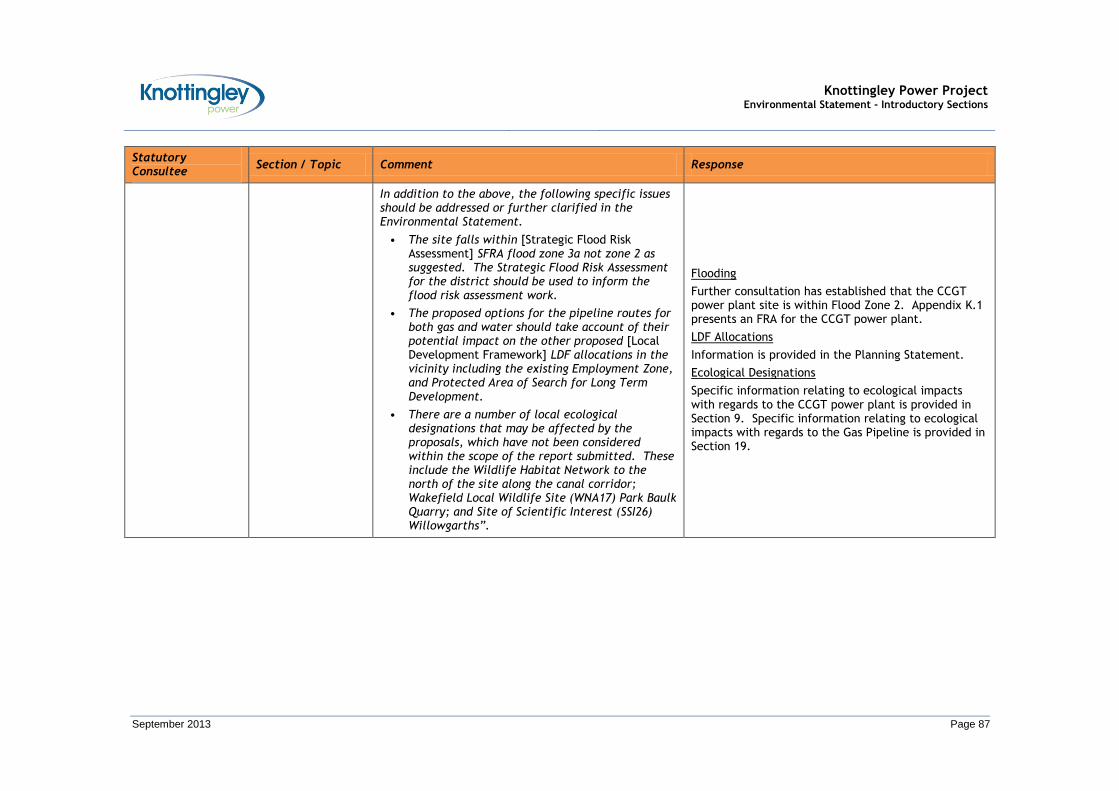
Knottingley Power Project Environmental Statement - Introductory Sections
September 2013 Page 87
Statutory Consultee
Section / Topic Comment Response
In addition to the above, the following specific issues should be addressed or further clarified in the Environmental Statement.
• The site falls within [Strategic Flood Risk Assessment] SFRA flood zone 3a not zone 2 as suggested. The Strategic Flood Risk Assessment for the district should be used to inform the flood risk assessment work.
• The proposed options for the pipeline routes for both gas and water should take account of their potential impact on the other proposed [Local Development Framework] LDF allocations in the vicinity including the existing Employment Zone, and Protected Area of Search for Long Term Development.
• There are a number of local ecological designations that may be affected by the proposals, which have not been considered within the scope of the report submitted. These include the Wildlife Habitat Network to the north of the site along the canal corridor; Wakefield Local Wildlife Site (WNA17) Park Baulk Quarry; and Site of Scientific Interest (SSI26) Willowgarths”.
Flooding
Further consultation has established that the CCGT power plant site is within Flood Zone 2. Appendix K.1 presents an FRA for the CCGT power plant.
LDF Allocations
Information is provided in the Planning Statement.
Ecological Designations
Specific information relating to ecological impacts with regards to the CCGT power plant is provided in Section 9. Specific information relating to ecological impacts with regards to the Gas Pipeline is provided in Section 19.
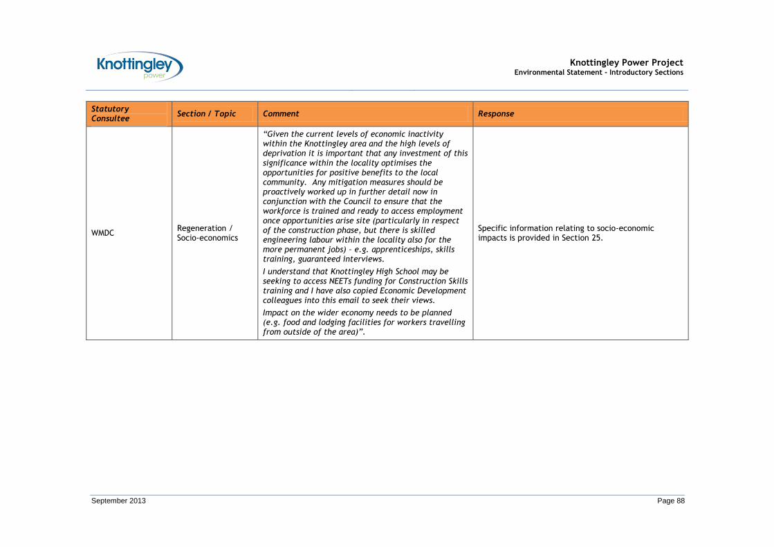
Knottingley Power Project Environmental Statement - Introductory Sections
September 2013 Page 88
Statutory Consultee
Section / Topic Comment Response
WMDC Regeneration / Socio-economics
“Given the current levels of economic inactivity within the Knottingley area and the high levels of deprivation it is important that any investment of this significance within the locality optimises the opportunities for positive benefits to the local community. Any mitigation measures should be proactively worked up in further detail now in conjunction with the Council to ensure that the workforce is trained and ready to access employment once opportunities arise site (particularly in respect of the construction phase, but there is skilled engineering labour within the locality also for the more permanent jobs) – e.g. apprenticeships, skills training, guaranteed interviews.
I understand that Knottingley High School may be seeking to access NEETs funding for Construction Skills training and I have also copied Economic Development colleagues into this email to seek their views.
Impact on the wider economy needs to be planned (e.g. food and lodging facilities for workers travelling from outside of the area)”.
Specific information relating to socio-economic impacts is provided in Section 25.

Knottingley Power Project Environmental Statement - Introductory Sections
September 2013 Page 89
Statutory Consultee
Section / Topic Comment Response
Regeneration – Landscape and Visual
“The site is within the proposed Knottingley masterplan boundary and I would hope that the design and layout of the site will be sensitive to the surrounding local area, e.g. landscape screening and shelter belt to protect visual amenity from the river, residential properties and key vantage points within the town; suitable highways access and routing of vehicles.
The river and canal have significant potential for leisure / recreational activities within the locality including walking, cycling, fishing, boating. The impact of ‘abstraction of significant quantities of water and discharge of water of up to 9⁰C warmer than ambient water temperature into an accessible water source (potentially river Aire or the Calder Navigation)’ should be appropriately managed to ensure that there is no negative impact on the bio-diversity and amenity of these areas for recreational purposes”.
Specific information relating to landscape and visual impacts with regards to the CCGT power plant is provided in Section 13.
Regeneration – Traffic, Transport and Access
“I am surprised that the report does not consider traffic impact to be significant during the construction phase. Locally residents and elected members report significant highways issues in respect of the A645, particularly [Heavy Goods Vehicle] HGVs, although this is not necessarily backed up by highways data. No doubt Highways colleagues will comment”.
Specific information relating to impacts on traffic, transport and access with regards to the CCGT power plant is provided in Section 15.

Knottingley Power Project Environmental Statement - Introductory Sections
September 2013 Page 90
Statutory Consultee
Section / Topic Comment Response
Regeneration – Combined Heat and Power (CHP)
“Combined Heat and Power - potential to be identified incorporating community, commercial and industrial heat uses and opportunities. I would be interested to know of any opportunities as they may arise.
I would hope that this scheme could positively contribute to the regeneration of Knottingley, not only through creation of jobs, but contribution to improvements throughout the local area, including open space contributions”.
A CHP Assessment is provided as Appendix F.1.
Ecology
“The desk top study for the project should include data searches with West Yorkshire Ecology and the North and East Yorkshire Ecological Data Centre. These should include records for locally designated sites and notable species. Note for example that Willowgarth is a Local Wildlife Site (see error in 5.5.6). We would also recommend that John Wint ([email protected]) a local ornithologist is consulted as he has undertaken a lot of studies at Beal Carrs which we believe is a Local Wildlife Site (SINC) in Selby”.
Specific information relating to ecological impacts with regards to the CCGT power plant is provided in Section 9.
Specific information relating to ecological impacts with regards to the Gas Pipeline is provided in Section 19.
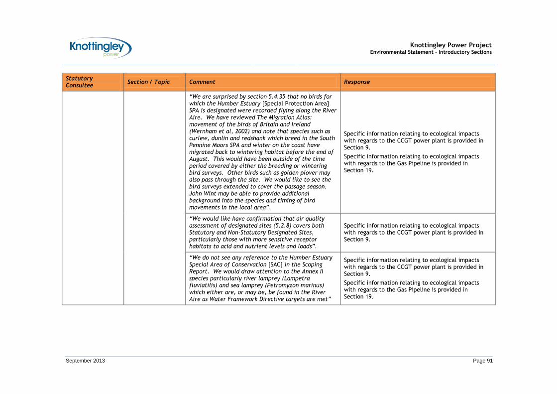
Knottingley Power Project Environmental Statement - Introductory Sections
September 2013 Page 91
Statutory Consultee
Section / Topic Comment Response
“We are surprised by section 5.4.35 that no birds for which the Humber Estuary [Special Protection Area] SPA is designated were recorded flying along the River Aire. We have reviewed The Migration Atlas: movement of the birds of Britain and Ireland (Wernham et al, 2002) and note that species such as curlew, dunlin and redshank which breed in the South Pennine Moors SPA and winter on the coast have migrated back to wintering habitat before the end of August. This would have been outside of the time period covered by either the breeding or wintering bird surveys. Other birds such as golden plover may also pass through the site. We would like to see the bird surveys extended to cover the passage season. John Wint may be able to provide additional background into the species and timing of bird movements in the local area”.
Specific information relating to ecological impacts with regards to the CCGT power plant is provided in Section 9.
Specific information relating to ecological impacts with regards to the Gas Pipeline is provided in Section 19.
“We would like have confirmation that air quality assessment of designated sites (5.2.8) covers both Statutory and Non-Statutory Designated Sites, particularly those with more sensitive receptor habitats to acid and nutrient levels and loads”.
Specific information relating to ecological impacts with regards to the CCGT power plant is provided in Section 9.
“We do not see any reference to the Humber Estuary Special Area of Conservation [SAC] in the Scoping Report. We would draw attention to the Annex II species particularly river lamprey (Lampetra fluviatilis) and sea lamprey (Petromyzon marinus) which either are, or may be, be found in the River Aire as Water Framework Directive targets are met”
Specific information relating to ecological impacts with regards to the CCGT power plant is provided in Section 9.
Specific information relating to ecological impacts with regards to the Gas Pipeline is provided in Section 19.

Knottingley Power Project Environmental Statement - Introductory Sections
September 2013 Page 92
Statutory Consultee
Section / Topic Comment Response
Leeds Bradford International Airport / Ecology
“As this proposed development is within our 13 km bird management zone we therefore ask that wildlife management is robust to ensure any attractants are mitigated and all is done to minimise risks”.
Specific information relating to ecological impacts with regards to the CCGT power plant is provided in Section 9.
Specific information relating to ecological impacts with regards to the Gas Pipeline is provided in Section 19.
Public Rights of Way (PRoW)
“The attached plan shows the public rights of way in the area by the dashed red lines.
In addition to the recorded public rights of way the solid red line indicates a claim that there are public rights over these routes.
The applicant indicates at Page 59 that there is informal public access over these routes. I have visited the site and can confirm that there is evidence of pedestrian, horse riding and cycle use along these routes. There is no physical evidence to suggest that the landowner has challenged public use.
I am of the opinion that there are public rights over the routes shown by the solid red line and these should be protected or suitable alternatives provided by the applicant.
Common Lane was highlighted by Public Rights of Way as a route to be protected / improved in the recent LDF site consultation”.
Specific information relating to impacts on traffic, transport and access with regards to the CCGT power plant is provided in Section 15.
Specific information relating to impacts on traffic, transport and access with regards to the Gas Pipeline is provided in Section 23.

Knottingley Power Project Environmental Statement - Introductory Sections
September 2013 Page 93
SECTION 5
ALTERNATIVES

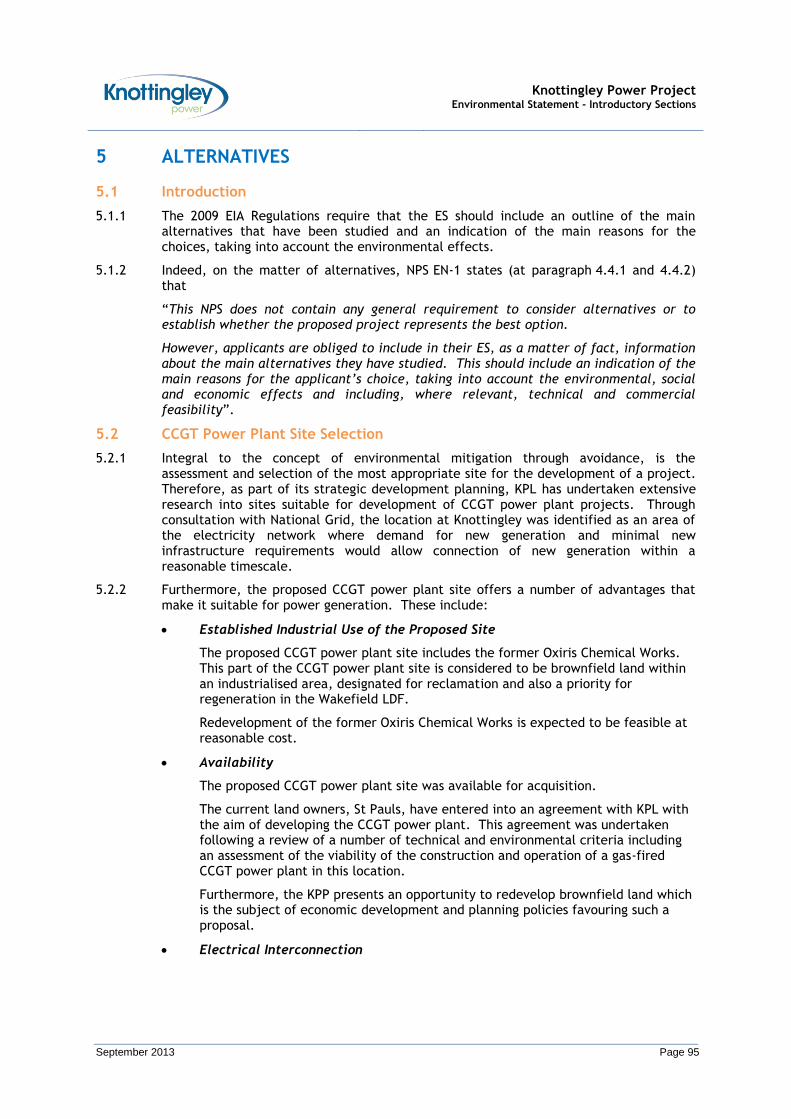
Knottingley Power Project Environmental Statement - Introductory Sections
September 2013 Page 95
5 ALTERNATIVES
5.1 Introduction
5.1.1 The 2009 EIA Regulations require that the ES should include an outline of the main alternatives that have been studied and an indication of the main reasons for the choices, taking into account the environmental effects.
5.1.2 Indeed, on the matter of alternatives, NPS EN-1 states (at paragraph 4.4.1 and 4.4.2) that
“This NPS does not contain any general requirement to consider alternatives or to establish whether the proposed project represents the best option.
However, applicants are obliged to include in their ES, as a matter of fact, information about the main alternatives they have studied. This should include an indication of the main reasons for the applicant’s choice, taking into account the environmental, social and economic effects and including, where relevant, technical and commercial feasibility”.
5.2 CCGT Power Plant Site Selection
5.2.1 Integral to the concept of environmental mitigation through avoidance, is the assessment and selection of the most appropriate site for the development of a project. Therefore, as part of its strategic development planning, KPL has undertaken extensive research into sites suitable for development of CCGT power plant projects. Through consultation with National Grid, the location at Knottingley was identified as an area of the electricity network where demand for new generation and minimal new infrastructure requirements would allow connection of new generation within a reasonable timescale.
5.2.2 Furthermore, the proposed CCGT power plant site offers a number of advantages that make it suitable for power generation. These include:
Established Industrial Use of the Proposed Site
The proposed CCGT power plant site includes the former Oxiris Chemical Works. This part of the CCGT power plant site is considered to be brownfield land within an industrialised area, designated for reclamation and also a priority for regeneration in the Wakefield LDF.
Redevelopment of the former Oxiris Chemical Works is expected to be feasible at reasonable cost.
Availability
The proposed CCGT power plant site was available for acquisition.
The current land owners, St Pauls, have entered into an agreement with KPL with the aim of developing the CCGT power plant. This agreement was undertaken following a review of a number of technical and environmental criteria including an assessment of the viability of the construction and operation of a gas-fired CCGT power plant in this location.
Furthermore, the KPP presents an opportunity to redevelop brownfield land which is the subject of economic development and planning policies favouring such a proposal.
Electrical Interconnection
Knottingley Power Project Environmental Statement - Introductory Sections
September 2013 Page 96
A site in close proximity to the electricity network (i.e. the National Grid Electricity Transmission System) is desirable to minimise the need for additional new infrastructure. Furthermore, the permitting of overhead lines can be onerous and transmission capacity is not available in many parts of the country, particularly the north.
With this in mind, the proposed CCGT power plant site is ideal as it is in close proximity to an existing 400 kV OHL situated within 250 m to the east of the CCGT power plant site.
Cooling Water Supply
The proposed site is in close proximity to suitable and acceptable quantities of water for cooling through either the River Aire, or the Aire and Calder Navigation Canal.
Gas Interconnection
A site in close proximity a suitable and optimal point at which to take gas from the existing UK National Grid Gas System is desirable.
The proposed CCGT power plant site is in close proximity to a number of potential points on the existing UK National Grid Gas System. Further information on the selection of the gas interconnection (i.e. the Gas Pipeline route evolution, selection and refinement) is provided below.
Transport Infrastructure
The proposed CCGT power plant site benefits from good transport infrastructure links, such as road, rail, and canal.
5.2.3 It is therefore considered that the proposed CCGT power plant site is very suitable for the intended use, that is power generation.
A Note on Alternatives
5.2.4 It is noted that whilst greenfield sites close to the existing National Grid Electricity and Gas Systems were initially considered, national planning policy and local planning policy aim to protect the countryside for its intrinsic value and encourage development of brownfield sites. Therefore this drives developers to consider ‘lower value sites’, such as the brownfield land / former chemical works site in Knottingley, in the first instance.
5.2.5 In addition, whilst the 2009 EIA Regulations require that the ES should include an outline of the main alternatives that have been studied, this is not a requirement if no alternative sites have been studies / investigated. KPL did not study or investigate alternative sites, or undertake an additional site selection study.
5.3 Gas Pipeline Route Evolution, Selection and Refinement
5.3.1 In the case of the Gas Pipeline, the main alternatives that have been considered are:
Alternative Options for Gas Supply; and
Alternative Gas Pipeline Routes, including:
o Alternative Connection Points; and
o Alternative Termination Points.
5.3.2 These alternatives are described in this Section.

Knottingley Power Project Environmental Statement - Introductory Sections
September 2013 Page 97
Background / Initial Area of Consideration
5.3.3 When considering the main alternatives, an initial area of consideration was used, roughly bounded by the M62, A1 / A162, A63 and A19.
5.3.4 The initial area of consideration is shown in Insert 5.1.
INSERT 5.1: AERIAL PHOTOGRAPH SHOWING THE INITIAL AREA OF CONSIDERATION
Alternative Options for Gas Supply
5.3.5 From a technical / engineering perspective, identification of potential routes for the Gas Pipeline began with establishing the optimal point at which to take gas from the existing UK National Grid Gas System.
5.3.6 The UK National Grid Gas System is split into two parts:
The National Transmission System, also known the UK Transmission System (UK-T); and
The Local Distribution System, also known as the UK Distribution System (UK-D).
National Transmission System
5.3.7 The National Transmission System represents the infrastructure designed to transmit gas around the country, and is the backbone of the UK gas infrastructure reaching all points of mainland Britain.
5.3.8 National Transmission System infrastructure is generally larger pipelines (greater than 24 inches / 600 millimetres (mm) in diameter) operating at high pressure (approximately 70 bar gauge (bar g)).
5.3.9 Within the vicinity of the CCGT power plant site, there are two 1200 mm high pressure steel National Transmission System pipelines. These are:

Knottingley Power Project Environmental Statement - Introductory Sections
September 2013 Page 98
Feeder 29 (Pannal to Asselby); and,
Feeder 7 (Pannal to Asselby Duplicate).
5.3.10 Feeder 29 was commissioned for use on the National Transmission System in 200811, and was introduced to reinforce a section of Feeder 7. Feeder 29 pipeline passes less than 7 km from the CCGT power plant site at its nearest point.
5.3.11 Feeder 7 is located north of Feeder 29, and presents another option to connect to the National Transmission System. However, Feeder 7 is 15 km away from the CCGT power plant site and therefore, would only be considered if capacity in Feeder 29 was unavailable.
5.3.12 The location of Feeder 29 (and the location of Feeder 7) is shown in Insert 5.2. The location of the CCGT power plant site is indicated by the red marker.
5.3.13 The nearest possible National Transmission System connection to the south has not been considered as this is over 50 km away near to Newark-on-Trent.
INSERT 5.2: NATIONAL TRANSMISSION SYSTEM SHOWING THE ROUTEING OF FEEDER 7 AND FEEDER 29
5.3.14 The National Transmission System connects into the Local Distribution System, which distributes the gas supply to where it is required.
Local Distribution System
5.3.15 The Local Distribution System is comprised of generally smaller pipelines (less than 24 inches / 600 mm in diameter) operating at lower pressure (approximately less than 50 barg).
11 See information on: http://www.nationalgrid.com/uk/Gas/Data/News/delaystofeeder2926092008.htm

Knottingley Power Project Environmental Statement - Introductory Sections
September 2013 Page 99
5.3.16 To connect the CCGT power plant to the Local Distribution System, the presence of a suitably high pressure and large diameter pipeline in the local area is required. There are two high pressure / large diameter pipelines (belonging to the Local Distribution System) in the area of consideration. These are:
The ‘Knottingley to Chapel Haddlesey’ line; and,
The ‘Barwick to Knottingley’ line.
5.3.17 The ‘Knottingley to Chapel Haddlesey’ line supplies gas to the Knottingley AGI, and the ‘Barwick to Knottingley’ line transports gas away from Knottingley AGI.
5.3.18 The Knottingley AGI is situated approximately 700 m to the north west of the proposed CCGT power plant site and can be seen in Insert 5.3.
INSERT 5.3: LOCAL DISTRIBUTION SYSTEM SHOWING THE KNOTTINGLEY AGI
LEGEND
High Pressure Pipeline
Medium Pressure Pipeline
Low Pressure Pipeline
5.3.19 Insert 5.3 shows that (apart from the high pressure / large diameter pipelines) at the Knottingley AGI gas is supplied to:
A 200 mm high pressure pipeline that feeds into a 300 mm low pressure pipeline; and,
A 450 mm medium pressure pipeline.
Evaluation of Options for Gas Supply
5.3.20 The above options for gas supply were evaluated based on a qualitative analysis of their strengths and weaknesses. The evaluation considered a number of factors, including: technical; planning; land ownership; environmental; and, cost.
5.3.21 Table 5.1 presents a summary of the qualitative analysis undertaken.
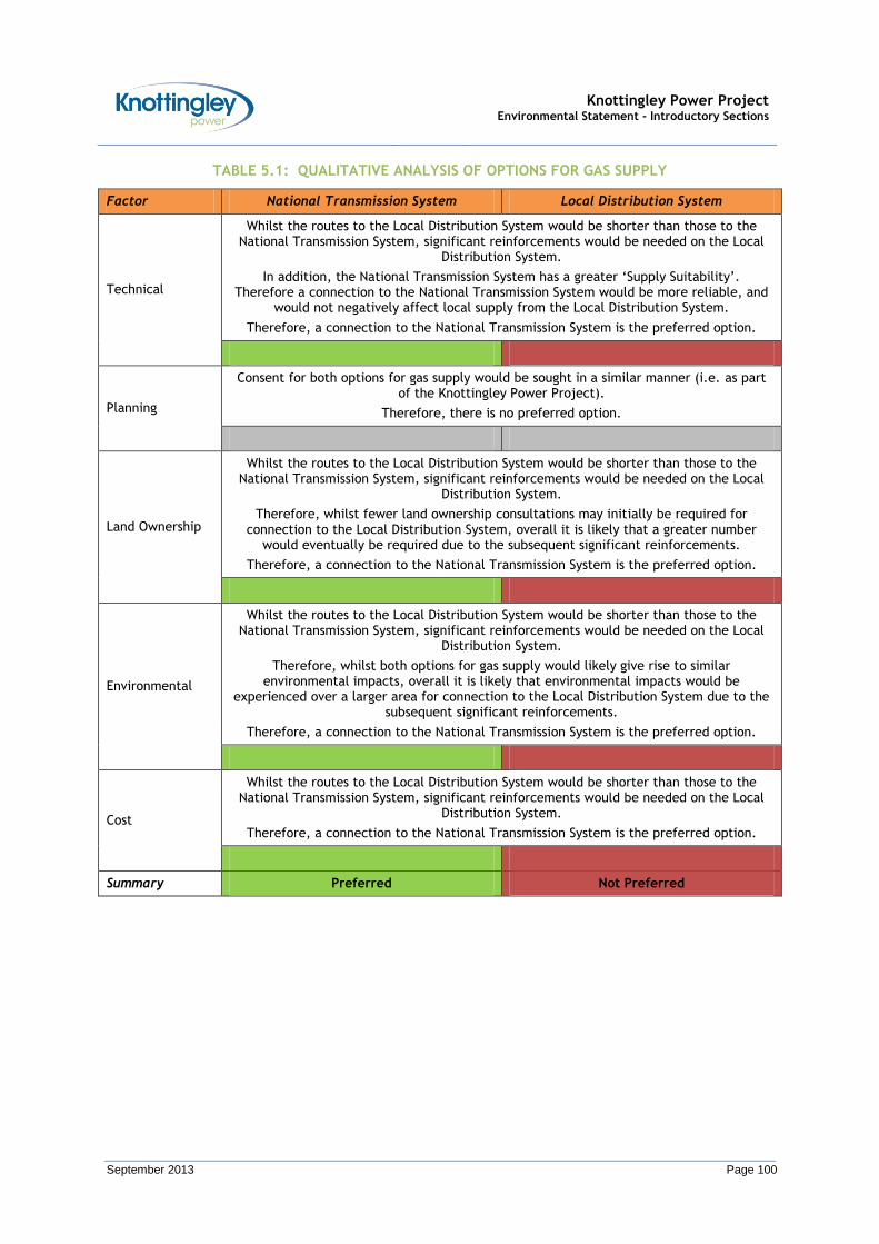
Knottingley Power Project Environmental Statement - Introductory Sections
September 2013 Page 100
TABLE 5.1: QUALITATIVE ANALYSIS OF OPTIONS FOR GAS SUPPLY
Factor National Transmission System Local Distribution System
Technical
Whilst the routes to the Local Distribution System would be shorter than those to the National Transmission System, significant reinforcements would be needed on the Local
Distribution System.
In addition, the National Transmission System has a greater ‘Supply Suitability’. Therefore a connection to the National Transmission System would be more reliable, and
would not negatively affect local supply from the Local Distribution System.
Therefore, a connection to the National Transmission System is the preferred option.
Planning
Consent for both options for gas supply would be sought in a similar manner (i.e. as part of the Knottingley Power Project).
Therefore, there is no preferred option.
Land Ownership
Whilst the routes to the Local Distribution System would be shorter than those to the National Transmission System, significant reinforcements would be needed on the Local
Distribution System.
Therefore, whilst fewer land ownership consultations may initially be required for connection to the Local Distribution System, overall it is likely that a greater number
would eventually be required due to the subsequent significant reinforcements.
Therefore, a connection to the National Transmission System is the preferred option.
Environmental
Whilst the routes to the Local Distribution System would be shorter than those to the National Transmission System, significant reinforcements would be needed on the Local
Distribution System.
Therefore, whilst both options for gas supply would likely give rise to similar environmental impacts, overall it is likely that environmental impacts would be
experienced over a larger area for connection to the Local Distribution System due to the subsequent significant reinforcements.
Therefore, a connection to the National Transmission System is the preferred option.
Cost
Whilst the routes to the Local Distribution System would be shorter than those to the National Transmission System, significant reinforcements would be needed on the Local
Distribution System.
Therefore, a connection to the National Transmission System is the preferred option.
Summary Preferred Not Preferred

Knottingley Power Project Environmental Statement - Introductory Sections
September 2013 Page 101
Preferred Option for Gas Supply
5.3.22 The options for gas supply considered further are those from the National Transmission System.
Alternative Gas Pipeline Routes
5.3.23 Based on an option for gas supply from the National Transmission System, the next stages was to establish alternative Gas Pipeline routes12. Alternative Gas Pipeline routes were established which aimed to satisfy the following criteria to reduce the impacts during construction / operation / decommissioning:
Routed away from habitation (and any potential future developments) as much as possible;
Routed to avoid significant environmental Statutory Designated Areas and Non-Statutory Designated Sites as much as possible;
Routed to avoid potentially difficult construction areas (i.e. severe slide slopes / solid rock strata / boggy land / landfill); and,
Routed to avoid an unnecessary length of pipeline being installed.
5.3.24 Accordingly, five alternative Gas Pipeline routes were identified. These were:
Route 1:
Route 1 takes a northerly exit from the CCGT power plant site, heading immediately under the Aire and Calder Navigation Canal and the A645 (Weeland Road).
Route 1 then turns north-east and continues on to Kellington. At Kellington, Route 1 turns towards the north, but is still heading in a roughly north-east direction.
Route 1 then crosses the River Aire, and continues north-east towards the National Transmission System.
The connection to the National Transmission System would be made south of Gateforth, off Pale Lane.
Route 1A:
Route 1A takes a northerly exit from the CCGT power plant site, heading immediately under the Aire and Calder Navigation Canal and the A645 (Weeland Road).
Route 1A turns north-east and follows Route 1 for approximately 400 m before turning north, thus diverging away from Route 1.
Route 1A crosses the River Aire, and continues north towards the National Transmission System.
The connection to the National Transmission System would be made near to Gateforth Hall, south of Hambleton.
12 Within the description of alternative Gas Pipeline route provided in this Section, the term ‘route’ is used to mean the linear route between the CCGT power plant site and the National Transmission System. The term ‘route’ in this context does not include consideration of the potential “working width” or proposed limits of deviation, which were not defined at this initial route selection stage.

Knottingley Power Project Environmental Statement - Introductory Sections
September 2013 Page 102
Route 2:
Route 2 takes an easterly exit from the CCGT power plant site, and continues east to cross Beal Lane. Route 2 then turns north to cross the Aire and Calder Navigation Canal.
Route 2 continues north, before joining and following Route 1.
The connection to the National Transmission System would be made south of Gateforth, off Pale Lane.
Route 2A:
Route 2A is similar to Route 2, but proposes a different option for crossing the Aire and Calder Navigation Canal.
Route 2B:
Route 2B is similar to Route 2, but proposes a different route for crossing the River Aire.
5.3.25 The five alternative Gas Pipeline routes can be seen in Figure 5.1.
5.3.26 For each of the five alternative Gas Pipeline routes, consideration also needed to be given to their associated connection point to the National Grid Gas Transmission System and termination point / entrance point on the CCGT power plant site.
Potential Connection Points (to the National Grid National Gas Transmission System)
5.3.27 As described above, Feeder 29 is considered to present the best option for connection to the National Transmission System. Based on this consideration, and in order to minimise the number of probable crossings, only a short section of Feeder 29 was considered for a connection point. This short section falls between the A63 and the A19. A connection point to Feeder 29 in this location would represent the shortest distance between the CCGT power plant site and Feeder 29, and would also limit the number of major crossings that must be considered.
5.3.28 Based on this, there are two potential options for the connection point to the National Transmission System. These are:
National Transmission System Connection Option 1: Connection point to the National Transmission System near to the Gateforth Hall, south of Hambleton.
National Transmission System Connection Option 2: Connection point to the National Transmission System south of Gateforth, off Pale Lane.
5.3.29 These options for the connection point to the National Transmission System are shown in Insert 5.4.

Knottingley Power Project Environmental Statement - Introductory Sections
September 2013 Page 103
INSERT 5.4: LOCATIONS OF THE POTENTIAL CONNECTION POINTS TO THE NATIONAL DISTRIBUTION SYSTEM
LEGEND
National Transmission
System Pipeline
Potential Connection
Point
Potential Termination Points (i.e. Entrance Points on the CCGT Power Plant Site)
5.3.30 Given there are no options for a connection point (to the National Grid National Transmission System) to the south, a southerly location for the entrance point for the Gas Pipeline on the CCGT power plant site was not considered. Likewise, as land to the west may be reserved for possible residential / light industrial applications, a westerly location for the entrance point for the Gas Pipeline on the CCGT power plant site was not considered.
5.3.31 Therefore, northerly and easterly locations for the entrance point for the Gas Pipeline on the CCGT power plant site were considered. These locations are shown in Insert 5.5.
5.3.32 From the entrance point, the Gas Pipeline will continue onwards to the termination point which will require a Gas Receiving Facility (GRF) where moisture is removed from the gas as necessary and the pressure adjusted for use in the gas turbines.

Knottingley Power Project Environmental Statement - Introductory Sections
September 2013 Page 104
INSERT 5.5: LOCATIONS OF THE POTENTIAL ENTRANCE POINTS ON THE CCGT POWER PLANT SITE
Evaluation of Alternative Gas Pipeline Routes (including Connection Points and Termination Points)
5.3.33 Table 5.2 presents a summary of the characteristics of the five alternative Gas Pipeline routes.
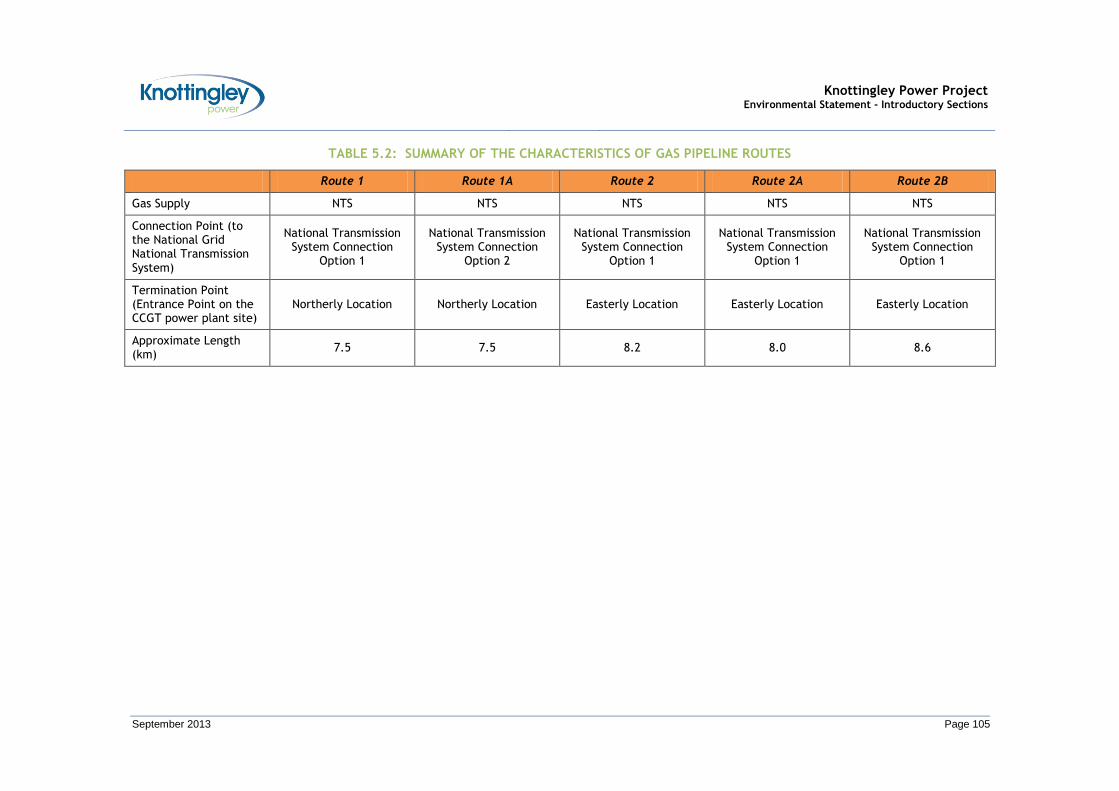
Knottingley Power Project Environmental Statement - Introductory Sections
September 2013 Page 105
TABLE 5.2: SUMMARY OF THE CHARACTERISTICS OF GAS PIPELINE ROUTES
Route 1 Route 1A Route 2 Route 2A Route 2B
Gas Supply NTS NTS NTS NTS NTS
Connection Point (to the National Grid National Transmission System)
National Transmission System Connection
Option 1
National Transmission System Connection
Option 2
National Transmission System Connection
Option 1
National Transmission System Connection
Option 1
National Transmission System Connection
Option 1
Termination Point (Entrance Point on the CCGT power plant site)
Northerly Location Northerly Location Easterly Location Easterly Location Easterly Location
Approximate Length (km)
7.5 7.5 8.2 8.0 8.6
Knottingley Power Project Environmental Statement - Introductory Sections
September 2013 Prepared by Parsons Brinckerhoff Page 106 for ESB International
Evaluation of Gas Pipeline Routes
Initial Evaluation / Initial Gas Pipeline Routes Presented
5.3.34 Of the five alternative Gas Pipeline routes, Routes 1A and 2B would cross an area currently being considered under a separate application for Planning Permission for the Prowind Wood Lane Wind Farm13.
5.3.35 Therefore, Routes 1A and 2B were discounted. Routes 1, 2 and 2A were taken forward for further consideration.
Further Evaluation / Section of Gas Pipeline Route
5.3.36 Routes 1, 2 and 2A were evaluated based on a qualitative analysis of their strengths and weaknesses.
5.3.37 The evaluation considered a number of factors, including: technical; planning; land ownership; environmental; and, cost.
5.3.38 Table 5.3 presents a summary of the qualitative analysis undertaken.
13 Information on the application available at: http://public.selby.gov.uk/online-applications/applicationDetails.do?activeTab=summary&keyVal=KJ62BUNX00U00
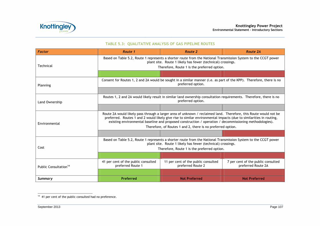
Knottingley Power Project Environmental Statement - Introductory Sections
September 2013 Page 107
TABLE 5.3: QUALITATIVE ANALYSIS OF GAS PIPELINE ROUTES
Factor Route 1 Route 2 Route 2A
Technical
Based on Table 5.2, Route 1 represents a shorter route from the National Transmission System to the CCGT power plant site. Route 1 likely has fewer (technical) crossings.
Therefore, Route 1 is the preferred option.
Planning
Consent for Routes 1, 2 and 2A would be sought in a similar manner (i.e. as part of the KPP). Therefore, there is no preferred option.
Land Ownership
Routes 1, 2 and 2A would likely result in similar land ownership consultation requirements. Therefore, there is no preferred option.
Environmental
Route 2A would likely pass through a larger area of unknown / reclaimed land. Therefore, this Route would not be preferred. Routes 1 and 2 would likely give rise to similar environmental impacts (due to similarities in routing,
existing environmental baseline and proposed construction / operation / decommissioning methodologies).
Therefore, of Routes 1 and 2, there is no preferred option.
Cost
Based on Table 5.2, Route 1 represents a shorter route from the National Transmission System to the CCGT power plant site. Route 1 likely has fewer (technical) crossings.
Therefore, Route 1 is the preferred option.
Public Consultation14
41 per cent of the public consulted preferred Route 1
11 per cent of the public consulted preferred Route 2
7 per cent of the public consulted preferred Route 2A
Summary Preferred Not Preferred Not Preferred
14 41 per cent of the public consulted had no preference.
Knottingley Power Project Environmental Statement - Introductory Sections
September 2013 Page 108
Preferred Gas Pipeline Route
5.3.39 Route 1 was selected as it represents the preferred option.
Gas Pipeline Route Refinement
Initial Route Refinement
5.3.40 Over the course of the EIA process, the route of the Gas Pipeline has evolved and a number of minor route refinements have been made. The initial minor route refinements are shown in Figure 5.2. These initial minor route refinements are all within the original ESR Assessment Corridor.
5.3.41 A summary of the initial minor route refinements are:
At the CCGT power plant site, minor route refinements have been undertaken such that the Gas Pipeline and the preferred entrance point for the Gas Pipeline on the CCGT power plant site are aligned;
To the north of the A645 (Weeland Road), minor route refinements have been undertaken due to the Gas Pipeline crossing land with Development Potential;
At Beal Carrs, minor route refinements have been undertaken such that the route of the Gas Pipeline is further to the east, thus avoiding the centre of the Beal Carrs area;
To the north of Birkin Road, minor route refinements have been undertaken based on the proposed turbine locations of the Prowind Wood Lane Wind Farm ; and,
South of Tom’s Wood, the minor refinements have been made to the location of the AGI based on Land Owner discussions.
Further Route Refinement
5.3.42 Further minor route refinements may also occur at the detailed design stage. This would be a result of: further Stakeholder Consultation; further Land Owner / Land Occupier negotiations; accuracy of existing pipeline / services / utilities information; and, further ground investigations.
5.3.43 Any such further minor route refinement would be limited and would take place within the limits of deviation of the DCO and the survey area covered by the impact assessments, as reported in this ES. Further information on the survey area for each of the environmental technical areas covered is provided in the Gas Pipeline Impact Assessment Sections.
5.3.44 In addition, it should be noted that as the final design, routeing and refinement of the Gas Pipeline has not yet been completed, the detailed approval of the final design and routeing of the Gas Pipeline will be included as a Requirement in the DCO (i.e. under the Requirement concerning ‘detailed design approval’).
Knottingley Power Project Environmental Statement - Introductory Sections
September 2013 Page 109
SECTION 6
DESCRIPTION OF THE DEVELOPMENT
Knottingley Power Project Environmental Statement - Introductory Sections
September 2013 Page 110
6 DESCRIPTION OF THE DEVELOPMENT
6.1 The Knottingley Power Project
6.1.1 KPL proposes to build and operate the KPP.
6.1.2 The KPP will be capable of generating up to 1500 MW (nominal) of electricity, equivalent to the annual electricity consumption of about two million homes.
6.1.3 The KPP comprises the following main elements:
The CCGT Power Plant:
This comprises a nominal 1500 MW (nominal) natural gas fired CCGT power plant. In terms of the CCGT power plant, there are two potential layout options under consideration. These are:
1) Three 500 MW ‘units’; or,
2) Two 600 MW ‘units.
These are referred to as the 3-unit option and the 2-unit option respectively
The ES has been developed mainly using the three 500 MW units option, which would be expected to have the larger environmental effect. Where the two 600 MW unit option could give rise to likely significant environmental effects that are greater than or materially different from those assessed for the three 500 MW unit option then these effects have also been addressed.
A further description of the CCGT power plant site and the CCGT power plant is provided in Section 6.2 and Section 6.3 respectively.
Information on construction / operation / decommissioning of the CCGT power plant is provided in Section 6.4.
The Grid Connection:
The electricity generated by the CCGT power plant will be exported to the National Grid Electricity Transmission System. It is proposed that the Grid Connection is made immediately to the east of the CCGT power plant site, to the existing National Grid 400 kV Electricity Transmission System.
The Grid Connection will include an OHL connection from the electricity substation at the CCGT power plant to the National Grid 400 kV Transmission System. It also includes the slight diversion of the existing OHL requiring the replacement of two existing transmission towers (pylons) adjacent to the current tower locations.
A further description of the Grid Connection is provided in Section 6.6.
The Cooling Water Infrastructure:
It is proposed that cooling water will be supplied from the River Aire, or from the Aire and Calder Navigation Canal for use in the hybrid cooling tower system. This will require Cooling Water Pipelines for abstraction and purge flows, and associated pumping station.
Water from the hybrid cooling tower system will be returned to the river / canal at a temperature up to 9°C warmer than the ambient water temperature.
If the River Aire is chosen to supply cooling water, the Cooling Water Pipelines will run in parallel north from the CCGT power plant site to the pumping station on
Knottingley Power Project Environmental Statement - Introductory Sections
September 2013 Page 111
the southern bank of the River Aire. If the Aire and Calder Navigation Canal is chosen, the Cooling Water Pipelines will run in parallel to the pumping station on the northern boundary of the CCGT power plant site.
A further description of the Cooling Water Infrastructure is provided in Section 6.8.
The Gas Pipeline:
The CCGT power plant will be fuelled by a supply of natural gas.
The supply of natural gas will be taken from a new Gas Pipeline (together with associated infrastructure, principally an AGI) which will be constructed between the CCGT power plant site and the National Grid National Gas Transmission System.
A further description of the Gas Pipeline is provided in Section 6.10.
6.1.4 The main elements of the KPP are shown on Figure 1.1.
6.1.5 The proposed construction / operation / decommissioning dates are as follows:
Start of Construction: 2015
Commissioning: 2017
Commercial Operation: 2018
Decommissioning15: 2043
6.1.6 The KPP will be designed for an operational lifetime of at least 25 years.
6.2 Description of the CCGT Power Plant Site and its surroundings
6.2.1 The CCGT power plant site is located approximately 3 km east of Knottingley, West Yorkshire on a 20 hectare (ha) site that includes the former Oxiris Chemical Works and adjoining agricultural land. The CCGT Power Plant site is centred at Ordnance Survey Grid Reference 451505E, 423285N.
6.2.2 The location of the CCGT power plant site is shown in Figure 6.1.
6.2.3 Other than Knottingley, the CCGT power plant site is located approximately 450 m north east of Kellingley, approximately 7 km north east of Pontefract town centre, approximately 9.5 km south east of Castleford, 13 km south west of Selby town centre, and 24 km south east of Leeds town centre.
6.2.4 The CCGT power plant site is bounded to the north by the Aire and Calder Navigation Canal and Kellingley Colliery to the north east. Kellingley Colliery is a deep mine operated by UK Coal. The CCGT power plant site is bounded to the south by a railway line, running east to west, with agricultural land and residential properties to the south and west.
6.2.5 The CCGT power plant site is located within the administrative boundary of WMDC, and the boundary of SDC is 70 m to the north east. The boundary of NYCC is concurrent with the boundary of SDC.
6.2.6 The CCGT power plant site is accessed from the A645 (Weeland Road) along Common Lane. The CCGT power plant site will share Common Lane with existing businesses located along Common Lane. To the west, the A645 (Weeland Road) runs through Knottingley to the A1(M) and M62. To the east, the A645 (Weeland Road) runs through Eggborough to the A19 and M62. Therefore the CCGT power plant site has access to the
15 Assuming a 25 year design lifetime of the CCGT power plant.

Knottingley Power Project Environmental Statement - Introductory Sections
September 2013 Page 112
strategic highways network. Further details of the access to the CCGT power plant site are provided in Section 15 (Transport, Traffic and Access).
6.2.7 Historically the CCGT power plant site comprised agricultural fields divided by Common Lane. Based on information provided by former chemical works employees and from maps published by the Ordnance Survey it is understood that development of a chemical works on the western part of the CCGT power plant site was commenced by Yorkshire Tar Distillers in 1949 on land that had previously been in agricultural usage.
6.2.8 The chemical works operated continuously until shortly before it was demolished in 2009. The north-western part of the CCGT power plant site now consists of vacant derelict land including areas of hardstanding. There are also occasional small derelict buildings near the former chemical works entrance, on the western part of the CCGT Power Plant site. The eastern and southern parts of the site continue to comprise agricultural fields.
6.2.9 The closest residential property is located beyond the Aire and Calder Navigation Canal, on the A645 (Weeland Road), approximately 100 m north of the CCGT power plant site. To the south west, the nearest residential properties are located in the residential area of Broomhill, approximately 250 m from the CCGT power plant site. To the west, the nearest residential properties are located at Springfields, approximately 500 m from the CCGT power plant site.
6.2.10 Further information on the CCGT power plant site (and its surroundings) is included in the baseline description provided in each of the specialist Impact Sections.
6.3 Description of the CCGT Power Plant
Processes facilitating Electrical Power Generation
6.3.1 The CCGT power plant comprises a number of processes facilitating electrical power generation. These processes include:
Combustion of natural gas in gas turbines to directly generate electricity;
Production of steam from the waste heat released from the gas turbines;
Use of steam in steam turbines to generate additional electricity;
Cooling of residual steam;
Release of combustion gases;
Export of electricity from the site; and,
Management of residues produced by this process.
6.3.2 These processes will occur within different buildings, areas and structures as shown in Figures 6.2 (for the 3-unit layout), and Figures 6.3 (for the 2-unit layout). The Design and Access Statement that accompanies the application for the DCO provides a description of the design principles that have been used to derive the current layouts.
6.3.3 A schematic of the processes facilitating electrical power generation is provided below in Insert 6.1.
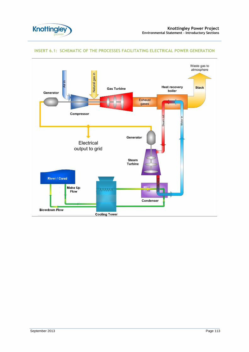
Knottingley Power Project Environmental Statement - Introductory Sections
September 2013 Page 113
INSERT 6.1: SCHEMATIC OF THE PROCESSES FACILITATING ELECTRICAL POWER GENERATION

Knottingley Power Project Environmental Statement - Introductory Sections
September 2013 Page 114
6.3.4 The term ‘combined cycle’ (within the definition of a CCGT power plant) refers to the use of two processes (or thermodynamic cycles) which are used for electrical power generation. These are:
Process / Thermodynamic Cycle 1 – The Gas Turbine Cycle (Brayton Cycle)
Within the gas turbine cycle, air is drawn through filters and compressed. The compressed air is then mixed with the natural gas fuel in the gas turbine combustor and burned at high temperature and pressure. The hot expanding gases pass through the gas turbine which is coupled to the electrical generator.
The hot exhaust gases (at a temperature of around 630ºC) exiting the gas turbine still contain useful energy, and are passed to a Heat Recovery Steam Generator (HRSG16) to generate high pressure steam. Within the HRSG, the feed water flows through heat transfer sections (banks of externally finned steel tubes) counter to the flow of the hot exhaust gases. HRSGs may be vertical or horizontal, with forced or natural circulation. This choice does not have any environmental implications.
Accordingly, the feed water is progressively heated and evaporated (i.e. turned to steam). The steam is then passed through a super-heater section where it is further heated to generate the high pressure steam.
In a large CCGT power plant, such as the KPP, the steam will usually be generated at three pressure levels achieving the optimal utilisation of the energy available in the hot exhaust gases.
In generating the high pressure steam, the hot exhaust gases will be cooled in the HRSG (to a temperature of around 95°C) and are then discharged to atmosphere, via an appropriately designed stack. Each HRSG will have its own dedicated stack, resulting in up to three main stacks on site (associated with the 3-unit option).
The HRSGs will not be supplementary fired, and will be specifically designed to match the operating characteristics of the gas turbines (and associated steam turbine equipment) to provide optimum performance for the CCGT power plant.
Process / Thermodynamic Cycle 2 - The Steam Cycle (Rankine Cycle)
Within the steam cycle, the steam raised in the HRSG is passed to steam turbine equipment in order to drive an electrical generator.
The spent steam discharged from the steam turbine equipment is passed to the condenser where it is cooled and condensed, and is then returned to the HRSG for re-use.
6.3.5 The use of these two processes captures more of the energy contained in the natural gas and, therefore, modern CCGT power plants represent an advanced power generation technology offering higher operating efficiencies, coupled with lower emissions per unit of electricity generated over other power generation technologies.
6.3.6 Furthermore, the combined cycle process can be made more efficient still by the use of the spent steam from the steam turbine for either an industrial process or for space heating (i.e. by operating the CCGT power plant in a CHP mode). The feasibility operating the CCGT power plant in a CHP mode has been assessed in the CHP Assessment which is presented in Appendix F.1.
6.3.7 The gas turbines and steam turbine equipment in each unit are likely to be located in a common Turbine Hall, which will comprise a clad steel structure with brickwork on the
16 A HRSG is sometimes referred to as a Waste Heat Recovery Boiler.

Knottingley Power Project Environmental Statement - Introductory Sections
September 2013 Page 115
lower level. Exhaust gas ducting, carrying the hot exhaust gases exiting the gas turbines, will connect the gas turbine to the HRSG which will be located within its own enclosure adjacent to the Turbine Hall. Steam piping, carrying the high pressure steam exiting the HRSG, will connect the HRSG back to the steam turbine in the Turbine Hall.
CCGT Power Plant Site Layout
6.3.8 The CCGT power plant site can be split into two main areas:
The CCGT power plant area to the east; and,
The CCR area in the west.
6.3.9 The CCGT power plant area is described below. The CCR area will be used as a laydown area during the construction phase, and subsequently reserved for a future carbon capture facility.
The CCGT Power Plant Area
6.3.10 The CCGT power plant area accommodates the power generating structures, cooling structures, auxiliary structures and administration buildings. These structures are described in this Section. The size and dimensions of the structures are listed in Table 6.1.
Power Generating Structures
6.3.11 As mentioned previously, there are two potential layout options under consideration: the 3-unit option and the 2-unit option. The layout of the two options is shown in Figures 6.2 and Figure 6.3 respectively.
6.3.12 Irrespective of which option is selected, the units are likely to be situated on the western part of the CCGT power plant Area. Each unit is likely to be laid out in an east-west orientation and to lie abreast.
6.3.13 Each unit will consist of the following features:
A single gas turbine and associated electrical generator to facilitate the direct production of electricity from the combustion of natural gas;
A HRSG used to recover heat from the hot exhaust gases exiting the gas turbine;
Steam turbine equipment and associated electrical generator to facilitate the supplementary production of electricity from the steam produced by the HRSG;
A HRSG stack (each unit will have a stack that is up to 75 m in height which will discharge combustion gas to the atmosphere); and,
A main transformer.
6.3.14 Each unit will also feature dedicated auxiliary structures / buildings containing plant items needed to support the operations of the power generating structures.
6.3.15 It should be noted that the power generating structures will require some additional auxiliary structures. These items are likely to be located with the auxiliary structures in the north western part of the CCGT power plant area.
Cooling Structures
6.3.16 Following an investigation into the most efficient method of cooling the power generation units, it was found that a water cooled system would be most appropriate. Under the current proposals, water for the water cooled system would be abstracted from the River Aire. Alternatively, water could be abstracted from the Aire and Calder Navigation Canal. A proportion of the water will be purged from the re-circulating

Knottingley Power Project Environmental Statement - Introductory Sections
September 2013 Page 116
cooling system and would then be discharged back to the river (or canal). In order to achieve this, cooling water pipelines will run from the CCGT power plant site to the River Aire (following the proposed Gas Pipeline route for much of the way) over a distance of approximately 1 km, or to the canal. Further information on the cooling water pipelines is provided in Section 6.8.
6.3.17 In terms of cooling the power generation units, two main components need to be considered. These are the surface condenser (which cools the exhaust steam from each steam turbine in a water-cooled tube for re-use within the steam cycle) and the closed cooling water circuit. The closed cooling water circuit cools the: gas turbine lubricating oil; generator hydrogen; boiler circulating pumps; sample coolers, and, other minor systems. The closed cooling water circuit will be filled with de-ionized water to which a suitable corrosion inhibitor will be added. The total volume of water in the closed cooling water circuit will be small, of the order of the order of 100 m3 and thus the quantity of corrosion inhibitor used will also be very small. Closed cooling water circuits will not normally produce an aqueous effluent. On the rare occasions when these circuits have to be drained for maintenance, the cooling water can be safely discharged at a low flow rate and allowed to mix with the other plant effluents.
6.3.18 The main cooling water system will cool both the condenser and the closed cooling water circuit.
6.3.19 Accordingly, each power generating unit will have a corresponding bank of hybrid cooling towers. The banks of hybrid cooling towers are likely to be located on the eastern part of the CCGT power plant area. The banks will lie abreast of each other and will be arranged generally on a north east to south west axis. For the 3-unit option, three banks of cooling towers are proposed, each comprising approximately 10 cells. For the 2-unit option, two banks of cooling towers are proposed, each comprising approximately 11 cells. It should be noted that the cooling structures will require some additional auxiliary structures (i.e. water intake structure / water pre-treatment). These items are likely to be located with the auxiliary structures in the north western part of the CCGT power plant area.
6.3.20 Unlike the large 100 to 120 m tall hyperbolic cooling towers typically associated with older thermal power plant, the proposed hybrid cooling towers would have fans mounted on the top to force air through, thus permitting shorter towers, of the order of 18 m in height.
6.3.21 In addition, in order to control the production of visible moisture plumes, hybrid cooling towers have both dry and wet sections. Warm cooling water passes from the condenser to the dry section, which is located at the top of the hybrid cooling tower. Within the dry section, the warm cooling water passes through finned tubes where heat is transferred to the rising air and water vapour, producing warm air. The rising air and water vapour is heated above the dew point to reduce the occurrence of a visible plume. Indeed, the hybrid cooling towers will be designed to be plume free down to an ambient temperature of 5ºC and a relative humidity of 95%. Having passed through the dry section, the cooling water is passed to the wet section which is located in the lower section of the cooling tower. Within the wet section, the cooling water is sprayed over a packing system, where heat is transferred through direct contact with the air flowing up through the tower and also by evaporation. The packing system will comprise anti-fouling film packs supported on treated timber beams covering the entire cross section of the cooling towers.
6.3.22 In combining dry and wet sections, cooling is achieved through both the dry heat exchange and wet evaporative processes. The wet evaporative process is a very effective and efficient process. In terms of the visible plume, in the top of the cooling
Knottingley Power Project Environmental Statement - Introductory Sections
September 2013 Page 117
tower, damp air from the wet section is mixed with warm dry air from the dry section reducing the occurrence of a visible plume.
6.3.23 The plume from the cooling towers, although generally not visible, will contain clean water and, as such, is not a pollution risk.
6.3.24 The cooled cooling water exiting the wet section is collected in the cooling tower basin, from where it is re-circulated within the cooling system.
6.3.25 In order to avoid frost damage, minimise visual impact when necessary and maximise the efficiency of the system when the occurrence of a visible plume is not likely, the operation of the cooling towers can be optimised by varying the air flow and the extent of usage of the dry and wet sections.
Water Required for Cooling Structures
6.3.26 As noted, the water for the water cooled system will be abstracted from either the River Aire or the Aire and Calder Navigation Canal. The water will be required to replace losses due to purging and evaporation.
6.3.27 To control the suspended solids and minerals in the river/ canal water, it is envisaged that the raw abstracted water will be filtered and treated prior to use. The suspended solids removed by the filters will be either dewatered in a filter press, or backwashed and disposed of to sewer. The water will be treated with a biocide and a proprietary dispersant to control fouling and the growth of micro-organisms. However, even after this filtering and treatment, the river / canal water will still contain solids and minerals which will become concentrated within the cooling system due to the evaporation which takes place in the cooling towers. In order to prevent the levels of these impurities from increasing above levels where corrosion and deposition can occur, it is necessary to continually purge (blow-down / discharge) a proportion of the water from the cooling system and replace with freshly abstracted river / canal water.
6.3.28 In addition to this purge, freshly abstracted water is also required as make up for the evaporation and (to a lesser extent) drift (i.e. where fine droplets of water are blown from the towers (for example) due to wind blowing across the base of the cooling towers) losses.
6.3.29 The water will be drawn from the river / canal via two 50% duty pumps. The purge will be returned to the river / canal up to 9°C warmer.
6.3.30 The only significant addition to the abstracted water will be small concentrations of the biocide sodium hypochlorite, which is aimed at achieving a free chlorine concentration within the re-circulating cooling system that is sufficient to prevent nuisance growths of organisms. A free chlorine level of 0.2 to 0.5 mg/l at the condenser inlet is required to limit growth of slimes, while >1 mg/l is typically required to control algal growth. The chlorine content in the cooling water will not be discharged should the residual chlorine level exceed 0.2 mg/l.
6.3.31 The cooling system will have a re-circulating flow rate of approximately 35 m3/s of water. In summertime (which represents a worst case in terms of amounts of abstracted water), at an evaporation rate of 1.1 %, approximately 0.39 m3/s will be lost to atmosphere due to evaporation. A concentration factor within the cooling system would lead to a requirement to purge up to approximately 0.18 m3/s of water. Therefore, the maximum make–up flow (which arises in summertime) is the sum of the evaporative loss plus purge flow, and is up to approximately 0.58 m3/s.
Knottingley Power Project Environmental Statement - Introductory Sections
September 2013 Page 118
Administration Buildings
6.3.32 The two main administrative buildings are likely to be located in the north eastern part of the CCGT power plant area, immediately to the north of the power generating structures.
6.3.33 In addition to these administrative buildings, there will be an internal network of roads, footways and car parking as well as a security building and gatehouse.
Auxiliary Structures
6.3.34 Most of the auxiliary structures are likely to be located in the north western part of the CCGT power plant area, immediately to the west of the main administration buildings. However, there are also a number of auxiliary structures associated with the import of natural gas. These are located in the south eastern part of the CCGT power plant area.
6.3.35 A description of a number of these auxiliary structures is provided in this Section.
Auxiliary Boiler
6.3.36 A small (approximately 25 MW) gas fired auxiliary boiler will be installed to provide steam to enable start-up of the steam turbine equipment.
6.3.37 During start-up, the auxiliary boiler would provide steam (which would normally be provided by the HRSGs) for: de-aeration of the feed water / condensate before its introduction into the main boiler; warming the steam piping and steam turbine gland system; and, establishing the condenser vacuum. The auxiliary boiler would therefore operate intermittently, typically for a few hours at a time, when the HRSG is unavailable.
6.3.38 Feed water and steam systems of the auxiliary boiler would be connected to the feed water and steam systems supplying the main HRSGs. A separate blowdown system (local to the auxiliary boiler) would be provided which would cool the purge water before being discharged to the main plant effluent system.
6.3.39 Chemicals will be injected directly into the auxiliary boiler to prevent corrosion during periods of prolonged shutdown. These chemicals will be consistent with the chemicals used within the main HRSG system.
6.3.40 The auxiliary boiler will have up to two dedicated stacks, each of the order of 30 m tall.
Water Treatment Plant
6.3.41 Water quality in the steam cycle will be controlled by continuously purging or ‘blowing down’ small quantities of the water / steam from the system to ensure optimal efficiency. This water is replaced with high purity demineralised water supplied by an on-site Water Treatment Plant and stored in a treated water storage tank.
6.3.42 The Water Treatment Plant will treat water from the town mains water using either ion exchange or reverse osmosis to produce high purity demineralised water. Typically, a Water Treatment Plant consists of: a water break tank; activated carbon filter; cation exchange beds; anion exchange beds; and, mixed bed units.
6.3.43 The treatment process will involve pre-treatment (e.g. filtration or clarification) followed by the exchanging of cations in the supply (i.e. calcium, magnesium, sodium) for hydrogen ions by using cation exchange resins, and then the exchanging of anions in the decationised water (i.e. sulphate, chloride, carbonate, silicate) for hydroxyl ions by using anion exchange resins.
6.3.44 Periodically the ion exchange beds will require regeneration, where the cations and anions removed from the raw water and held by the resins are displaced with hydroxide and hydrogen from a sodium hydroxide solution and an acid solution respectively. The
Knottingley Power Project Environmental Statement - Introductory Sections
September 2013 Page 119
acid used will comprise either hydrochloric or sulphuric acid. However, the use of sodium hydroxide and acid is not necessary if reverse osmosis using electro-deionisation is adopted.
6.3.45 A demineralised water storage tank will be located adjacent to the Water Treatment Plant. Storage tanks will also be required for the regeneration chemicals and for effluent neutralisation.
6.3.46 In addition, there will be a raw water storage tank which will hold up to approximately 3,500 m3 of water. This tank will provide a backup supply of water should the supply of towns mains water supply be disrupted. The raw water tanks would also provide fire fighting water to the proposed CCGT power plant site. This water supply should be adequate to meet the requirements for fire fighting, and will be confirmed by calculation.
6.3.47 The effluent produced by the Water Treatment Plant is discussed below.
Emergency Diesel Generator
6.3.48 A small 1 mega volt amp (MVA) emergency diesel generator will be installed.
6.3.49 The emergency diesel generator will enable safe shutdown of the CCGT power plant, and provide electricity for critical users (i.e. emergency lighting in the event of total loss of electrical supply). The emergency diesel generator will be tested on a routine basis, of the order of once every 14 days, to ensure that the emergency diesel generator plant starts properly when required. Such testing will only be of a few minutes duration.
Fire Fighting System
6.3.50 A fire fighting system will be implemented across the entire CCGT power plant site, which will be specified to be in accordance with UK and International standards. Whilst this system will be designed to be independent, without recourse to assistance from outside fire fighting services or facilities, access provision for local fire engines is to be made.
6.3.51 The gas turbine fire-fighting system will be based on an inert gas (e.g. CO2). In addition, an automatic high velocity water spray system for the protection of the turbine lubricating oil tank, coolers and associated pipe-work will also be provided. Heat sensors or smoke detectors will be used in conjunction with automatic spray nozzles.
6.3.52 Foam would be available to fight fires associated with any oil storage areas. Oil storage areas will be bunded, sized to contain 110% of the capacity of the tanks / drums. Following the fire event the foam / oil contained in the bunds will be treated / disposed offsite by a licensed waste contractor.
6.3.53 Other areas will use water spray and deluge, connected to a fire water ring main. To ensure that the fire water ring main is continually pressurised, a small electric jockey pump will be used. In the event of a fire, firewater will be supplied to the fire water ring main by the main electrically driven fire water pump with a diesel pump available as backup. The pump(s) will start automatically in the event of low pressure in the fire water ring main, and will be located in the Fire Fighting Building.
6.3.54 Water for fire-fighting purposes will be stored in a dedicated part of the raw water storage tank.
6.3.55 The diesel fire fighting pump will have a rating / duty of around 0.1 MW and will be fired on low sulphur diesel supplied from a bunded diesel tank local to the pump. The pump engine will discharge to atmosphere through a stack located above the roof of the Fire Fighting Building. The diesel fire fighting pump will be tested on a routine basis, of the
Knottingley Power Project Environmental Statement - Introductory Sections
September 2013 Page 120
order of once every 14 days, to ensure that the plant starts properly when required. Such testing will only be for a few minutes. Emissions to atmosphere from the diesel fire fighting pump engine will not be significant.
6.3.56 The relatively small quantities of other materials stored on site (e.g. water treatment chemicals, lubricating oils) will be adequately bunded to contain any contaminated firewater in the event of a fire. Therefore, further firewater retention measures are not considered necessary.
Balance of Plant
6.3.57 The remainder of the auxiliary structures will include air compressing equipment, a gas filtering, metering and compression station, electrical switchgear and control equipment.
6.3.58 In addition, the CCGT power plant will employ standard mechanical and electrical protective devices, including: venting and emergency relief valves; shut-down sequence controls; safety interlocks; fault detection; and, alarm systems.
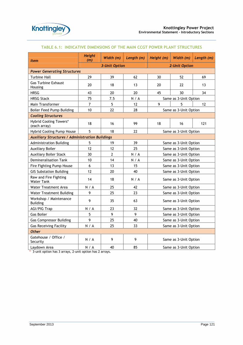
Knottingley Power Project Environmental Statement - Introductory Sections
September 2013 Page 121
TABLE 6.1: INDICATIVE DIMENSIONS OF THE MAIN CCGT POWER PLANT STRUCTURES
Item
Height (m)
Width (m) Length (m) Height (m) Width (m) Length (m)
3-Unit Option 2-Unit Option
Power Generating Structures
Turbine Hall 29 39 62 30 52 69
Gas Turbine Exhaust Housing
20 18 13 20 22 13
HRSG 43 20 20 45 30 34
HRSG Stack 75 7.5 N / A Same as 3-Unit Option
Main Transformer 7 5 12 9 5 12
Boiler Feed Pump Building 10 22 28 Same as 3-Unit Option
Cooling Structures
Hybrid Cooling Towers* (each array)
18 16 99 18 16 121
Hybrid Cooling Pump House 5 18 22 Same as 3-Unit Option
Auxiliary Structures / Administration Buildings
Administration Building 5 19 39 Same as 3-Unit Option
Auxiliary Boiler 12 12 25 Same as 3-Unit Option
Auxiliary Boiler Stack 30 2 N / A Same as 3-Unit Option
Demineralisation Tank 10 14 N / A Same as 3-Unit Option
Fire Fighting Pump House 6 13 15 Same as 3-Unit Option
GIS Substation Building 12 20 40 Same as 3-Unit Option
Raw and Fire Fighting Water Tank
14 18 N / A Same as 3-Unit Option
Water Treatment Area N / A 25 42 Same as 3-Unit Option
Water Treatment Building 9 25 23 Same as 3-Unit Option
Workshop / Maintenance Building
9 35 63 Same as 3-Unit Option
AGI/PIG Trap N / A 23 32 Same as 3-Unit Option
Gas Boiler 5 9 9 Same as 3-Unit Option
Gas Compressor Building 9 25 40 Same as 3-Unit Option
Gas Receiving Facility N / A 25 33 Same as 3-Unit Option
Other
Gatehouse / Office / Security
N / A 9 9 Same as 3-Unit Option
Laydown Area N / A 40 85 Same as 3-Unit Option * 3-unit option has 3 arrays, 2-unit option has 2 arrays.
Knottingley Power Project Environmental Statement - Introductory Sections
September 2013 Page 122
Material Requirements
Fuel
6.3.59 The CCGT power plant will be fuelled by a supply of natural gas. The supply of natural gas will be taken from a new Gas Pipeline (together with associated infrastructure, principally an AGI) which will be constructed between the CCGT power plant site and the National Grid National Gas Transmission System. A further description of the Gas Pipeline is provided in Section 6.10.
6.3.60 On the CCGT power plant site, the Gas Pipeline will run from the northern boundary to the gas filtering, metering and compression station, on the south eastern part of the CCGT power plant site. The compound will contain filtering, metering, pressure reduction and heating equipment to supply natural gas at the correct temperature and pressure to the gas turbines.
6.3.61 The fuel supply contract will specify the analysis of the fuel which will comply with the National Grid standard specification. Whilst the natural gas will be of the same quality as that supplied to domestic properties, it will not be odorised. Therefore its sulphur content will be negligible. The natural gas will have a net Calorific Value of approximately 46.6 megajoules per kilogram (MJ/kg).
6.3.62 Venting and emergency relief valves will be provided to enable safe start up, shut-down and operation and maintenance of the natural gas supply system.
Water
6.3.63 Towns water will be required daily under normal operating conditions:
To supply the Water Treatment Plant (to be used as make-up water to the steam cycle, and as wash waters);
To supply the fire fighting system;
For service water; and,
For potable water.
6.3.64 In addition to the towns water, up to approximately 0.58 cubic metres per second (m3/s) of water will be abstracted from the river / canal for use in the water cooled system. Due to evaporation losses, a lower flow rate of approximately 0.18 m3/s will be returned to the river / canal. An application for a licence to abstract water from the River Aire was made to the Environment Agency in December 2012, and was granted in July 2013.
6.3.65 Periodic water use audits will be undertaken to ensure that the quantities of water used (both towns water and water abstracted from the river / canal) are minimised.
Miscellaneous Materials
6.3.66 Operation of a CCGT power plant naturally involves the use of many chemicals, particularly as part of the steam cycle water dosing (for corrosion control), cooling system dosing (for control of biological growths in the cooling water circuits) and water treatment. Many of these chemicals require stringent procedures for their storage and use, and this is a normal part of operation. Only small quantities of such chemicals will be stored on site.
6.3.67 Steam cycle water dosing chemicals will comprise:
Ammonia or other neutralizing amine – a pH buffering agent;
Carbohydrazide, hydrazine or other oxygen scavenger;
Trisodium phosphate;
Knottingley Power Project Environmental Statement - Introductory Sections
September 2013 Page 123
Anti-scalants; and,
Dispersants.
6.3.68 Cooling water dosing chemicals will comprise:
Biocide – most likely sodium hypochlorite;
Sulphuric acid; and,
Anti-scalants
6.3.69 Water treatment chemicals will comprise:
Sodium hydroxide; and
Sulphuric or hydrochloric acid.
6.3.70 Lubricating oils will be used to lubricate the gas and steam turbines. Used lubricating oils will also be stored on the site for re-use or will be disposed of off-site by an approved and licensed contractor in accordance with applicable regulations. Transformer oil will be used in oil-cooled transformers. Occasional top up or replacement will be required. Spent transformer oil will be returned to the manufacturer. Other miscellaneous materials (such as oils, greases, cleaning substances and materials) will also be required.
6.3.71 All above-ground tanks containing liquids whose spillage could be harmful to the environment will be bunded. All bunds will:
Be impermeable and resistant to the stored materials;
Have no outlet (that is, no drains or taps);
Have pipework routed within bunded areas with no penetration of contained surfaces;
Be designed to catch leaks from tanks or fittings;
Have a capacity greater than 110 percent of the largest tank or 25 percent of the total tankage, whichever is the larger;
Be subject to regular visual inspection and any contents pumped out or otherwise removed under manual control after checking for contamination, or where not frequently inspected, be fitted with a high-level probe and an alarm;
Where possible, have tanker connection points within the bund; and,
Be subject to programmed engineering inspection (normally visual, but extending to water testing where structural integrity is in doubt).
6.3.72 If hydrochloric acid is used, then the hydrochloric acid tank will contain a scrubber comprising a water washing system.
6.3.73 Storage areas for intermediate bulk carriers, drums, bags, etc., will be designed and operated to minimise the risk of releases to the environment. In particular:
Storage areas will be lined with hardstanding and will be located away from the boundary of the site close to the Aire and Calder Navigation Canal;
Storage areas will be protected against vandalism;
Storage areas will have appropriate signs and notices and be clearly marked-out, and all containers and packages will be clearly labelled;

Knottingley Power Project Environmental Statement - Introductory Sections
September 2013 Page 124
The maximum storage capacity of storage areas will be stated and not exceeded;
The maximum storage period for containers will be specified and adhered to;
Appropriate storage facilities will be provided for substances with special requirements (e.g. flammable, sensitive to heat or light) and formal arrangements will be in hand to keep separate packages containing incompatible substances (both “pure” and waste);
Containers will be stored with lids, caps and valves secured and in place (this also applies to emptied containers);
All stocks of containers, drums and small packages will be regularly inspected (at least weekly); and,
Procedures will be in place to deal with damaged or leaking containers.
6.3.74 Wherever appropriate, storage facilities will be designed, situated and used with regard to Control of Substances Hazardous to Health (COSHH) Regulations 2002 (as amended).
Air Pollution Control
6.3.75 The CCGT power plant will employ ‘best available techniques’ to maximise the efficient use of energy.
6.3.76 In terms of air pollution control, there are two control measures that have been incorporated in to the design of the CCGT power plant to minimise the adverse impacts on air quality.
6.3.77 The first control measure is the selected combustion process that will be used, which will based on modern ‘dry low [nitrogen oxides] NOx’ combustion technology. This process will reduce the level of emissions by automated temperature control within the combustor, rather than (as in older CCGT power plants) using water or steam for temperature control. Furthermore, emissions from the CCGT power plant will be in full compliance with the requirements of Directive 2010/75/EU on industrial emissions (integrated pollution prevention and control) (the Industrial Emissions Directive (IED)).
6.3.78 The second control measure is designing the stack so that the emissions that are released from the CCGT power plant will disperse in such a manner that national air quality objectives will not be exceeded. In order to achieve this, the proposed height of the stack has been determined by atmospheric dispersion modelling. The stack will incorporate sampling points for manual measurements and connections for continuous emissions monitoring equipment. Further information is provided in Section 7 (Air Quality).
6.3.79 Furthermore, a load management scheme to match load and demand (thereby optimising energy supply) will be implemented. Within the load management scheme, the use of high efficiency electrical drives on equipment, regular preventative maintenance on equipment, and the use of thermal insulation will further ensure the employment of ‘best available techniques’. The load management scheme will be part of the overall energy management scheme that will form part of the Environmental Management System (EMS) to be implemented.
Solid Wastes Produced
6.3.80 The use of natural gas as fuel ensures no solid wastes are produced in the combustion process.
6.3.81 Accordingly, intermittent solid wastes are minimal and are restricted to the following:
Used gas turbine intake filters (typically replaced annually);

Knottingley Power Project Environmental Statement - Introductory Sections
September 2013 Page 125
Used ion exchange resins (typically replaced at 5 year intervals);
Suspended solids removed from river water;
Compressor wash water;
Separated oil / sludge from oil / water separators;
Used oil or chemical containers;
Solid waste from the sewage treatment plant, if installed;
Laboratory waste; and,
General office waste.
6.3.82 These wastes will be returned to the original supplier where possible or removed by an appropriate licensed contractor under the Environmental Protection (Duty of Care) Regulations 1991. In addition, the wastes will be segregated, and the quantity / nature / origin recorded prior to treatment or disposal. A waste audit will be undertaken on a four yearly basis in order to ensure the above wastes are reduced or recycled wherever possible.
Potential Future Development
Combined Heat and Power
6.3.83 As outlined in NPS EN-2, to support the application for a DCO, a CHP Assessment has been undertaken. This is provided in Appendix F.1.
6.3.84 CHP is the simultaneous generation of electrical power and usable heat in a single process (this is also known as co-generation). Generating electrical power and heat together is a single process is more efficient than generating them separately, thus delivering a reduction in both primary energy usage and carbon emissions.
6.3.85 The CHP Assessment concluded that:
There are some large industrial users of heat in the area. However, at present, there appears to be limited appetite to engage with KPL for the supply of heat. Therefore, at present, it is considered that there are no large heat users in the local area.
There has been no response from the local social housing scheme.
Without heat users, at this stage it would not be economically feasible to operate the CCGT power plant as a CHP plant. In addition, it would not be technologically practical to convert the CCGT power plant into a CHP plant.
However, the area surrounding the CCGT power plant site has been identified in the Site Specific Allocations Development Plan Documents (DPD) as an area that it is preferred for new housing. If this is progressed, it is recommended that the CCGT power plant is built to enable condenser water heat to be extracted and used if needed as a pre-heat for heat pump (or boiler) district heating for the new housing. Therefore, although no heat users exist at the moment, the CCGT power plant should be designed to allow for future modification to enable steam to be extracted and used should suitable opportunities arise.
Carbon Capture
6.3.86 As the CCGT power plant exceeds the 300 MW threshold as outlined in NPS EN-2, it will be designed to be CCR. To support the application for a DCO, a CCR Feasibility Study has been undertaken. This is provided in Appendix F.2.
Knottingley Power Project Environmental Statement - Introductory Sections
September 2013 Page 126
6.4 CCGT Power Plant – Construction / Operation / Decommissioning
Construction
Construction Process
6.4.1 Following the approval of the DCO by the SoS, award of the construction contract and the detailed design of the CCGT power plant, it is anticipated that it would take around 40 months to construct the CCGT power plant.
6.4.2 In awarding the construction contract, a main contractor would be engaged following a competitive tendering process to undertake the overall CCGT power plant project work including: civil engineering works; mechanical engineering works; and, electrical engineering works. In undertaking detailed design, the main contractor would develop the detailed design, based on the minimum functional specification, and manage the development of the design.
6.4.3 In addition, the main contractor would be responsible for organising the CCGT power plant construction and installation works to the required safety standards and programme. For specific tasks, the main contractor would appoint specialist sub-contractors.
Site Preparation
6.4.4 Throughout construction, an information board will be displayed in a publicly accessible location, giving the name and telephone number of the developer’s site representative. Warning signs would also be erected.
6.4.5 Initial site preparation works will largely comprise site clearance (although the former chemical works site will have already been remediated by the current site owner). Following site clearance, further ground investigations (geotechnical and chemical) will be undertaken to confirm the remediated ground conditions. Any hot spots encountered would be de-lineated by an environmental engineer present on-site. Contaminated materials from these hot spots will be either: (1) treated accordingly and replaced; or, (2) disposed of to landfill. Following the ground investigations, validation testing will be undertaken to ensure that the remediation has been successful and to provide baseline data for the Environmental Permit for the CCGT power plant site. Provision for future monitoring will be made, where appropriate.
Temporary Construction Laydown Area
6.4.6 A temporary construction laydown area will be required during the construction phase. This area will be used for storage, fabrication and temporary site facilities (including the main contractor’s temporary site office and car parking).
6.4.7 This area will be on hardstanding which will be retained after construction. This area will be in the future CCR area within the CCGT power plant site.
Main Construction Works
6.4.8 The main construction works will follow a straightforward sequence beginning with initial stages for the excavation for structural foundations and structural development. The final stages would be for the installation of the CCGT power plant equipment followed by commissioning activities and the handover period.
6.4.9 A landscaping strategy, to be agreed with the planning authority and relevant consultees / stakeholders, would then be implemented.
6.4.10 The CCGT power plant buildings and structures will be founded on reinforced concrete foundations. Piled foundations are typically required for larger heavier equipment such as the gas turbines, HRSGs, steam turbines and generators. The final selection of the
Knottingley Power Project Environmental Statement - Introductory Sections
September 2013 Page 127
foundation types will be made during the detailed design phase. Circular tanks will be supported on reinforced concrete ring beams. Pipe racks will also be supported on reinforced concrete piles. Foundations for rotating or vibrating equipment will be designed in accordance with specified conditions to ensure that there will be no settlement of the units that could affect their operation. All construction surplus and waste materials will be regularly removed from the CCGT power plant site to an approved waste management site. All hazardous wastes and waste containers will be stored on the CCGT power plant site in an appropriate manner before removal by a licensed contractor for disposal by an approved method.
Commissioning
6.4.11 Commissioning of the CCGT power plant will be carried out in phases over a period of approximately 30 weeks. This will be progressive from final erection checks, to pre-commissioning and setting to work of individual component parts, through to the overall testing. The commissioning will prove the technical acceptance of the CCGT power plant.
6.4.12 Reliability tests will demonstrate the fitness for purpose of the CCGT power plant prior to commercial operation. Performance tests will demonstrate that the CCGT power plant complies with the performance guarantees, including emission limits. Availability and reliability will be demonstrated by operating the CCGT power plant under commercial conditions for a period without major repair to any item of plant or equipment.
Monitoring
6.4.13 KPL will monitor the construction of the CCGT power plant, and will retain the services of specialist environmental consultants / advisors for assistance with environmental monitoring and the preparation of detailed method statements. Accordingly, throughout construction KPL will liaise with and co-ordinate the activities of these environmental consultants / advisors.
Construction Workforce (During Construction)
6.4.14 A construction workforce of approximately 600 personnel on average is expected, although for a short period at the peak of construction approximately 1 100 personnel may be onsite. However this is dependent on the requirements of the main contractor (and the associated sub-contractors). This construction workforce would not be on-site for the duration of the construction period, and average numbers would be of the order of 400 personnel. The peak workforce would be onsite during the busiest construction period when multiple disciplines of contractors complete work simultaneously. Local contractors will be encouraged to tender for the civil and electrical works. Electricians, riggers, crane operators and heavy equipment operators will also be required.
Construction Hours
6.4.15 Initially, and until the main buildings / structures are closed and capable of providing an ‘indoor working environment’, construction work will be confined to the following times:
Monday to Friday: 07:00 to 19:00; and,
Saturday: 08:00 to 18:00.
6.4.16 Pile driving (for the piled foundations) will be limited to the following times:
Monday to Friday: 08:00 to 18:00; and,
Saturday: 08:00 to 14:00.
Knottingley Power Project Environmental Statement - Introductory Sections
September 2013 Page 128
6.4.17 No work external to buildings will be undertaken outside these times, on a Sunday or a Bank Holiday unless otherwise agreed with the local authorities or in an emergency.
Construction Environmental Management Plan
6.4.18 In order to ensure that environmental considerations are addressed, KPL will prepare a Framework CEMP, which will be used by the construction contractor as a basis for their CEMP. The purpose of the Framework CEMP is to:
Provide a mechanism for ensuring that measures to reduce, prevent and (where possible) offset potentially significant adverse environmental impacts (identified in this ES) are implemented;
Ensure that best practices are adopted and maintained throughout construction;
Provide assurance to third parties that their requirements with respect to environmental conditions and performance will be met;
Provide a mechanism for ensuring compliance with legislative guidelines and requirements; and,
Provide a framework against which to monitor and audit environmental performance.
6.4.19 Further details are provided in Section 27 (Framework for a Construction Environmental Management Plan).
Operation
6.4.20 During operation, and to meet the expected electricity demand profile, it is expected that the CCGT power plant will operate in one of three operating scenarios:
At base load (most likely during the winter months);
In two shift mode (i.e. a few hours in morning and evening); or,
At reduced load (most likely during the night).
6.4.21 For operation at base load, the CCGT power plant will be operating at full load (i.e. its maximum design capability) on a continuous basis.
6.4.22 For operation in two shift mode, the CCGT power plant will also be operating at full load. However this will be in order to meet the hours of peak demand, and as such would operate at full load in a shift mode (i.e. for a few hours each morning (perhaps between 7:00 to 10:00) and again for a few hours each evening (perhaps between 16:00 and 20:00).
6.4.23 For operation at reduced load, the load on the CCGT power plant could drop to 30% of its maximum design capability in order to operate as Spinning Reserve Plant. Spinning Reserve Plant is called on when other power generating plant already in operation cannot maintain the stability of the National Grid (i.e. when the electricity demand exceeds supply). Spinning Reserve Plant can rapidly increase load and supply additional power within seconds.
6.4.24 The CCGT power plant will be operated in accordance with an Environmental Permit issued by the Environment Agency under the Environmental Permitting (England and Wales) Regulations 2010. The EA has confirmed in discussions that sequential applications are acceptable (i.e. DCO application followed by Environmental Permit application at a later date). The EA has assigned a case reference number to the Project (EPR/RP3431CZ/A001).
6.4.25 A comprehensive accredited EMS will be developed before commencement of operation.

Knottingley Power Project Environmental Statement - Introductory Sections
September 2013 Page 129
6.4.26 The plant will be designed for high levels of automatic operation with an aim of minimum operator intervention. Full facilities for interfacing information on the automatic operation (and also for interfacing information on the control and alarm systems) will be installed so that the plant can be monitored from the central control room. Process parameters from the automatic operation will be continuously monitored and recorded within the central control room to ensure correct and efficient operation of the plant. Indeed, the central control room will serve as the centre of operations within the majority of plant functions being initiated and monitored.
6.4.27 The operating system will also include monitoring alarms and trending information from the process monitoring / continuous emissions monitoring systems, and any significant deviations will be alarmed and corrections carried out on occurrence. Records of performance and deviation will be maintained. As a component of the Environmental Permit, records of prescribed substance emissions will be required to be submitted to the Environment Agency and placed on the public register.
6.4.28 The control system for the power plant will provide for the proposed three operating scenarios.
6.4.29 Roving operators will assist during start-up and shut-down, and will ensure that the plant continues to operate satisfactorily, identifying and remedying minor leaks and malfunctions. Furthermore, the central control room will include a control console for start-up, on-line operation, and shutdown of each gas turbine and steam turbine unit. Prior to start-up, the operating personnel place the unit in the ‘ready-to-start’ state. Once ready, the unit may be automatically started and, once operating, the unit may be controlled either automatically or manually. Similarly, the central control room will include a control console for automatic shutdown.
6.4.30 Each year there will be a planned outage for maintenance, the length of this varying over a 3 year cycle. Indeed, a plant outage is generally required after every 8 000 operating hours equivalent for minor maintenance and after every 24 000 operating hours equivalent for major maintenance. Maintenance will be carried out by an appointed contractor and sufficient spares will be held on site to facilitate reliable operation of the plant and ensure that plant availability remains high. Maintenance will normally be planned on a long term basis and will usually be conducted in the summer months when demand for electricity is typically at its lowest. However, it should be noted that this ES is based on operation throughout the year.
6.4.31 The design of buildings, enclosures and plant will also minimise regular and long term maintenance. Materials and finishes will be chosen to ensure a cohesive appearance with the existing buildings on site.
Site Workforce (During Operation)
6.4.32 An operational workforce of approximately 50 personnel is expected. Skilled disciplines required during operation include (but are not limited to):
Operators;
Electrical engineers;
Mechanical engineers;
Craftsmen (mechanical and electrical / instrumentation);
Fuel handlers (drivers);
Control and instrumentation engineers;
Performance and environmental specialists;
Knottingley Power Project Environmental Statement - Introductory Sections
September 2013 Page 130
Fuel and power trading personnel;
Security; and,
Office administrators.
6.4.33 Approximately half (25 personnel) will be on site during typical office hours, namely the nine hours between 08:00 to 17:00 hours. The remaining half will be on a nine hour shift pattern with a one hour overlap. Accordingly, the shift pattern (and associated required personnel) will be as follows:
07:00 to 16:00 = 10 personnel;
08:00 to 17:00 = 25 personnel;
15:00 to 00:00 = 10 personnel; and,
23:00 to 08:00 = 5 personnel.
6.4.34 Personnel at all levels will receive training (appropriate to their job function) related to process and emission control, environmental management and health and safety.
Start-Up
6.4.35 The methods of start-up of the plant will vary depending on the initial conditions of the major equipment. Indeed, the time required for the plant to start and achieve full rating depends on the temperature and pressure conditions of the HRSG and steam turbine plant. In turn, these will depend on the duration of the shut-down period, the operating load prior to shutdown and ambient air temperature.
6.4.36 In general, following an 8 to 12 hour shut-down period from base load operation, the CCGT power plant is considered hot. After a shut-down period greater than 48 hours, the CCGT power plant is considered cold. Initial plant start-up, synchronisation and loading will normally take 1 to 1.5 hours from ‘cold’ to full load.
6.4.37 The auxiliary boiler is designed to aid fast start-up as it will maintain plant temperatures during short or overnight shut-down periods.
Abnormal Operations
6.4.38 Correction or shut-down procedures would be initiated where a breach of the conditions of the Environmental Permit is recorded.
6.4.39 In the event of a gas turbine or HRSG trip, the unit will shut-down. In the event of a steam turbine trip, a by-pass round the steam turbine will open, steam will be dumped to the steam condenser, with the gas turbine normally remaining in operation. During this time, atmospheric emissions are unchanged.
Power Supply to Operational Aspects of the Plant
6.4.40 In the event of a local power failure, the plant will be capable of operating without the supply of electricity from the National Grid. In this instance, power generated by the steam turbine plant will be used to sustain the operation of the CCGT power plant until the normal power supply is restored.
6.4.41 The CCGT power plant will also employ an Uninterruptible Power Supply (UPS) and, in certain circumstances, a standby emergency generator set, that will allow the CCGT power plant to maintain all critical systems.
Emergency Access and Egress
6.4.42 Emergency access and egress from the CCGT power plant site will be via the site entrance.
Knottingley Power Project Environmental Statement - Introductory Sections
September 2013 Page 131
Site Safety Transport Considerations
6.4.43 Internal traffic speed will be limited to 10 miles per hour (mph) (16 kilometres per hour (kph)) and appropriate signage specifying speed limits and providing directions for delivery drivers will be provided. Signage will be designed and located to meet the requirements of British Standard (BS) 8300 (Code of practice for access to buildings for disabled people) and the Joint Mobility Unit (JMU): Sign Design Guide.
6.4.44 Furthermore, all staff and subcontractors working on the CCGT power plant site will be required to undergo a site induction training course that will include consideration of measures to avoid workplace transport accidents. These measures will include (but not be limited to):
All vehicles to be safe, well maintained and fit for their intended purpose;
Persons using vehicles and transport to have appropriate qualifications and training;
Wherever possible, avoidance of the need for reversing activities (where this is not possible, and a banksman is used, standard hand signals for directing vehicles to be implemented);
The use of high-visibility clothing for staff working around vehicles and the quay (on the canal) area and other transport activities;
Guaranteeing that parked vehicles cannot move, or be moved unintentionally;
The restriction that people must not be carried on vehicles unless they have a proper seat; and,
The implementation of warning systems wherever people could be crushed or trapped by vehicles.
Decommissioning
6.4.45 At the end of this operational lifetime, the CCGT power plant will be decommissioned and the site reinstated as agreed with the relevant authorities. Decommissioning would take into account of the environmental legislation and the technology available at the time. Any necessary licences or permits would be acquired.
6.4.46 Alternatively, if market conditions and / or electricity supply constraints at that time indicate that it would be appropriate to extend the life of the CCGT power plant, then decommissioning may be deferred to a later date. Indeed, it is not uncommon for power plant such as the proposed CCGT power plant to operate for 40 years or more. In order to ensure continuing adequate operational conditions and performance, the CCGT power plant would be re-engineered and re-permitted as required, dependent upon the legislation, legislative guidelines and requirements at that time.
6.4.47 The costs of decommissioning will be borne by the operator, and are usually covered by the recycling value of certain items of plant.
6.4.48 During decommissioning, the operator would develop a Decommissioning Plan. In order to ensure that environmental considerations are addressed, the operator will require the main contractor to prepare and implement a Decommissioning Environmental Management Plan (DEMP). The purpose of the DEMP will be similar to the CEMP. Furthermore, as part of the requirements under the Environmental Permit, a Site Closure Plan will have been prepared. This will be amended in accordance with any changes to the CCGT power plant over its lifetime.
6.4.49 The main decommissioning works will follow a straightforward sequence beginning with making the plant safe (in accordance with the relevant safety procedures). The plant

Knottingley Power Project Environmental Statement - Introductory Sections
September 2013 Page 132
would then be de-energised in conjunction with the Distribution Network Operator. Stored materials would be sold where possible or disposed of off-site by a licensed contractor. Storage tanks and pipes would be emptied. Closed vessels, pipes and other areas which could have hazardous gases present would be vented in accordance with normal operating procedures. These would then be tested to ensure that they are safe for removal or entry. Once the plant is completely disconnected, and all hazardous materials removed, it will be handed over to a competent contractor (or contractors) to complete the dismantling and demolition work.
6.4.50 It is probable that most of the plant and equipment will be at the end of its useful operating life and will be obsolescent or obsolete and unsuitable for further use. Therefore, it will need to be dismantled for recycling, where it is economic to do so. Unsalvageable material will be disposed of at a licensed landfill. Any remaining aqueous effluents would be disposed of in accordance with the normal operating licence or as agreed with the regulatory authorities.
6.4.51 Site buildings and structures would be removed to permit the future use of the site. Soils would be remediated to their former condition. Should there be no further development plans for the site, then a landscaping or habitat creation scheme may be agreed with the local authority, such as a community forest.
6.5 CCGT Power Plant – Safety Considerations
6.5.1 Safety is of fundamental importance during every stage of the planning, design, construction and subsequent operation of a CCGT power plant. This Section provides a brief description of the appropriate safety considerations to ensure compliance with the requirements of the HSE and ensure the safe operation of the CCGT power plant.
Planning / Design
6.5.2 A pre-contract Health and Safety Plan will be prepared in order to identify and address all potential health and safety hazards associated with the installation of the CCGT power plant in order to allow potential construction contractors to prepare for the Construction Stage Health and Safety Plan.
Construction
6.5.3 During construction, high safety standards and experienced site staff will be employed in order to minimise the risk of injury occurring on the construction site. The construction contractor will be required to adhere to the Construction Design and Management (CDM) Regulations 1994 (and amendments thereto).
6.5.4 Furthermore, site security will be strict. Unauthorised access to the construction site will be prevented by the use of temporary fencing. Any road access would comply with Highway Authority Guidelines. All traffic movements would be adequately controlled and supervised in accordance with a Construction Transport Management Plan (CTMP).
6.5.5 A temporary compound or container for the storage of equipment or materials would be provided. This will be locked with restricted access.
6.5.6 Security staff will be utilised at night and weekends and during non-working periods as appropriate.
6.5.7 All temporary oil storage tanks will be bunded to prevent uncontrolled release of potentially hazardous materials to the environment. However only very small quantities of oil will be stored on site, and these will not cause a risk to health or safety. These oils would not contain polychlorinated biphenyls (PCBs). Furthermore, implementation of appropriate spill prevention and control measures will ensure the risk of accidental release of potentially hazardous materials would be low throughout construction.

Knottingley Power Project Environmental Statement - Introductory Sections
September 2013 Page 133
Operation
6.5.8 During operation, procedures will be implemented to ensure that safety is maintained under all likely circumstances.
6.5.9 During operation, KPL will develop a site safety plan to regulate site activities on the CCGT power plant site to achieve the highest level of safety. Within the remit of the site safety plant, regular training and safety inspections will be carried out.
6.5.10 Full Health and Safety Risk Assessments will be carried out, and all recommended actions will be undertaken / implemented. Suitable training and precautions in the associated risks will be given to all personnel.
6.5.11 Integrated within the design of the CCGT power plant will be mechanisms for ensuring the highest standard of electrical safety and protection. Such mechanisms include:
Under the requirements of the Electricity Safety, Quality and Continuity Regulations 2002, compliance with current code of practices for the specification, design, installation and operation of electrical components and their connection to the distribution grid (including system analysis studies to ensure the integrity of the electrical distribution system is maintained during operation);
Monitoring of the CCGT power plant site by a closed circuit television (CCTV) camera system controlled from the control building, with CCTV cameras positioned to allow views, including those of sensitive locations (i.e. the main entrance, electrical sub-station / power station office); and,
The use of back-up systems or components. Indeed, modern turbine control and monitoring systems have several layers of redundancy to protect the plant from damage and protect the safety of the personnel working on the power plant.
6.5.12 The CCGT power plant site will not be a COMAH site.
Decommissioning
6.5.13 Safety issues during decommissioning will be controlled in accordance with guidance and regulations relevant at the time. It is anticipated that these will be similar to those outlined above for construction.
6.6 Description of the Grid Connection
6.6.1 The electricity generated by the CCGT power plant will be exported to the National Grid Electricity Transmission System. It is currently proposed that the Grid Connection is made immediately to the east of the CCGT power plant site, to the existing National Grid 400 kV Electricity Transmission System. The area set aside for the construction of the Grid Connection is centred at Ordnance Survey Grid Reference 451928E, 423154N.
6.6.2 The Grid Connection will include an overhead power line connection to the National Grid 400 kV Transmission System and the replacement of two existing transmission towers to be relocated adjacent to the current tower locations. In addition, a new gantry will be constructed adjacent to the Gas Insulated Switchgear (GIS) Building on the electricity substation. The electricity substation is to be constructed in the north eastern corner of the CCGT power plant area.
6.6.3 To facilitate the export of electricity, the electrical system of the CCGT power plant will include up to three gas turbine generators and three steam turbine generators which will be connected to Gas Insulated Switchgear through dedicated generator step-up transformers. The transformers will be oil-filled, outdoor-type transformers with forced oil and air cooling systems. The transformers will be appropriately bunded and fire-protected.

Knottingley Power Project Environmental Statement - Introductory Sections
September 2013 Page 134
6.6.4 The auxiliary electrical system of the CCGT power plant will consist of two voltage levels. The higher voltage level will be used to power large motors and the gas turbine static starting device. The lower voltage level will be used to supply plant motor loads, lighting and small power, battery chargers and uninterruptible power supplies.
6.7 Grid Connection – Construction / Operation / Decommissioning
6.7.1 This section describes the main components of the overhead electricity transmission line modification works including the construction of the replacement section of overhead line between towers (pylons) 4YR001 and 4YR004, an outline sequence of work for the undertaking of the proposed construction and details of the construction methods to be utilised.
Construction
6.7.2 Following the grant of the DCO by the SoS, further detailed design of the grid connection works will commence on the overhead line connection to the National Grid 400 kV Transmission System and the replacement of two existing transmission towers. The design and execution of the works will be carried out by National Grid.
6.7.3 To facilitate the new overhead connection to the substation in the CCGT power plant area, preliminary design carried out by National Grid has confirmed that it will be necessary to replace existing towers 4YR002 and 4YR003 on the 400 kV Eggborough - Ferrybridge C / Rochdale overhead line to the east of the proposed CCGT power plant site. These will be replaced by towers located adjacent to the current tower positions plus connections from tower 4YR003 into the proposed electricity substation to create a 400 kV Kellingley - Ferrybridge C circuit and a 400 kV Kellingley - Eggborough circuit. The 400 kV Eggborough - Rochdale circuit will be reinstated.
6.7.4 In order to facilitate the construction of the replacement towers, temporary overhead line diversions will be necessary, one of which will require construction of foundations for a temporary tower. These foundations will be left in place following removal of the temporary tower.
6.7.5 The section of existing overhead line affected by the work is 0.72 km in length and may require a full refurbishment, which will involve upgrading the existing conductor and earthwire systems, replacement of any corroded steelwork and upgrade of tower foundations as necessary. This will ensure the replacement line is suitable for a further 40 years of safe and reliable operation.
6.7.6 The replacement towers will be of standard design in use by National Grid and similar in appearance and height to the towers they will replace. Foundations for the replacement towers are likely to be piled. The pile length will be confirmed by site investigation prior to confirmation of final design.
6.7.7 Temporary works will be necessary in order to provide suitable access to and working areas at each tower site.
6.7.8 The proposed overhead line works will comprise the following sequence of work:
Surveys and Site Investigations;
Construction of temporary access and working areas;
Construction of one temporary mast and one temporary tower;
Construction of two replacement towers;
Realignment of 400 kV conductors and earthwire;
Dismantling of two existing towers; and,
Knottingley Power Project Environmental Statement - Introductory Sections
September 2013 Page 135
Connection into the new electricity substation.
6.7.9 Replacement of towers 4YR002 and 4YR003 will be carried out in a number of stages designed to maintain either circuit (Eggborough - Ferrybridge C and Eggborough - Rochdale) in operation throughout with minimal outage. From preliminary design considerations, the following stages are likely to be required.
Stage 1
6.7.10 Stage 1 will comprise the construction of a temporary stayed mast adjacent to existing tower 4YR002 to support the Eggborough - Rochdale circuit and allowing it to be removed from tower 4YR002. The activities in this stage will include:
Construction of temporary base and mast and associated stays at 4YR002T;
Outage of the Eggborough - Rochdale circuit;
Move phase conductors and earthwire between 4YR001 - 4YR003 via temporary mast 4YR002T; and,
Return Eggborough - Rochdale circuit to service.
Stage 2
6.7.11 Stage 2 will comprise the construction of a replacement tower 4YR002R and removal of 4YR002. The activities in this stage will include:
Outage of the Eggborough - Ferrybridge circuit;
Construction of new tower 4YR002R near 4YR002; and,
Demolition of 4YR002.
Stage 3
6.7.12 Stage 3 will comprise the construction of a temporary tower to carry the Eggborough - Ferrybridge C circuit and allowing it to be removed from tower 4YR003. The activities in this stage will include:
Construction of temporary tower 4YR003T near 4YR003;
Move phase conductors between span 4YR002 – 4YR004 via temporary tower 4YR003T; and,
Return Eggborough - Ferrybridge C circuit to service.
Stage 4
6.7.13 Stage 4 will include the construction of a replacement tower 4YR003R and removal of 4YR003. The activities in this stage will include:
Outage of Eggborough - Rochdale circuit;
Construct new tower 4YR003R near 4YR003; and,
Demolish tower 4YR003.
Stage 5
6.7.14 Stage 5 will comprise the removal of temporary mast 4YR003T. The activities in this stage will include:
Reinstatement of Eggborough - Rochdale circuit conductors 4YR001 – 4YR002R –4YR003R – 4YR004;
Removal of temporary mast 4YR002T; and,

Knottingley Power Project Environmental Statement - Introductory Sections
September 2013 Page 136
Return Eggborough - Rochdale circuit to service.
Stage 6
6.7.15 Stage 6 will comprise the removal of temporary tower 4YR003T. The activities in this stage will include:
Outage of Eggborough - Ferrybridge C circuit;
Reinstatement of Eggborough - Ferrybridge circuit conductors 4YR002 – 4YR003R – 4YR004;
Removal of temporary tower 4YR003T; and,
Return Eggborough - Ferrybridge C circuit to service
Stage 7
6.7.16 Following construction of the CCGT power plant and associated electricity substation, Stage 7 will comprise a further outage on the Eggborough-Ferrybridge C circuit. The activities in this stage will include:
Remove jumpers at tower 4YR003R;
Installation of downleads for connection of the CCGT power plant;
Commission new 400 kV Knottingley - Eggborough circuit; and,
Commission new 400 kV Knottingley - Ferrybridge C circuit.
Preparation Work and Access
6.7.17 Before construction activities commence along the new alignment, a precision ground survey will be carried out to confirm the ground profile both along the centre of the line and on either side where the ground profile slopes across the line route and also to confirm setting levels for the new towers. This will ensure that the new conductors will continue to maintain the statutory clearances.
6.7.18 Where the conductoring works might conflict with trees, the trees will be removed or reduced in height prior to the construction activity. This work will be carried out to avoid the March - August bird nesting period.
6.7.19 Temporary access roads will be required in particular in the vicinity of 4YR002 and 4YR003 and to the temporary mast and temporary tower. Vehicular access to every tower along the section of overhead line route affected will be required; routes and detailed arrangements will be agreed in advance with each landowner and occupier. Temporary stone working areas will also be required where new towers and the mast are to be erected.
6.7.20 Access roads will be installed following the stripping and storage of topsoil and the laying of a geo-textile blanket. All access routes and working areas will be clearly demarcated to ensure that the extent of the construction impact is contained to a reasonably practicable minimum. Typical access and working area activities fall into three categories:
1. Typical Working Areas at tower base (subject to local constraints);
2. Winch / Tensioner Areas (typically 60 m by 60 m with 30 m by 100 m corridors either direction beneath the line to site the winch and winched conductors); and,
3. Platform for Piling Rigs / Cranes / MEWPS Areas (subject to local constraints).
6.7.21 Netted scaffolds will be erected over third party operations in order to provide protection from any conductor system and earthwire movements. Existing distribution
Knottingley Power Project Environmental Statement - Introductory Sections
September 2013 Page 137
pole lines operated by Northern Powergrid at 11 kV, 33 kV and 66 kV will be re-routed in advance of work commencing.
6.7.22 Construction laydown areas will be required during the construction phase. The laydown areas will be used for storage, assembly and temporary site facilities (including the contractor’s welfare facilities). This area may be in the vicinity of 4YR002 and 4YR003 and / or on the adjacent CCGT power plant site if additional space is required.
6.7.23 Other than where work has to be undertaken at specific times to meet outage limitations, the grid connection works will be confined to the periods and times described in Section 6.4.
Installation of Tower Foundations
6.7.24 New towers foundations are likely to consist of piles with pile caps. Typical piling methods are driven steel tube, driven pre-cast concrete and augured piles. For all methods a specialist piling rig will be used at each tower site. Where more than one pile is required for a particular foundation, then the tops of each pile are joined together by encasing them in a concrete pile cap. The dimensions of each pile cap will differ depending on the type of tower to be installed. Following excavation for the pile caps on all four tower leg positions, steel stubs will be installed using a template to achieve the correct tower base dimensions and rake for each leg of the tower. Above ground tower steelwork will be attached to these stubs.
6.7.25 All excavations are fenced for protection and the pile caps concreted in position using formwork or shuttering. Concrete will be delivered by ready mixed concrete truck either direct to site or by 4 x 4 dumper vehicles, or by other means to minimise land damage. After a minimum period of 48 hours the concrete formwork is removed and the excavations backfilled and consolidated. The template is then removed from the steel stubs to be used again.
Installation of Tower Steelwork
6.7.26 The steelwork for all new tower sites will usually be delivered using a flat bed HGV. The assembly of each tower will be undertaken at ground level as far as possible until the utilisation of a crane is necessary to enable box-section assembly to be completed. It is normal practice to use cranes to erect steelwork, subject to suitable access being available. This reduces the timescale for construction, as well as the number of personnel and vehicle movements to / from the tower sites. Anti-climbing guards will be fitted to the tower at an early stage of erection.
Conductor Stringing
6.7.27 Having completed the erection of the new towers, the next stage will be to install the conductor and earthwire system. Prior to the commencement of any conductor works, the temporary installation of scaffolding and nets will be required to provide protection to obstructions directly beneath the overhead line, in this case the railway, the canal, buildings and roads in proximity to the coal site.
6.7.28 The conductor erection equipment and conductor drums for any new conductors will be transported to site by HGV. Full tension stringing methods will be used whereby a winch will be placed at one end of the section affected and a tensioner at the other. By winching the conductor through the section of overhead line under a constant tension, controlled by the application of brakes, the conductor will be erected without touching the ground, thus avoiding damage to both the conductors and any features beneath. The conductor will subsequently be tensioned to the correct value and clamped at each tension tower position. Running blocks will then be removed and spacers fitted between the sub-conductors of each phase.

Knottingley Power Project Environmental Statement - Introductory Sections
September 2013 Page 138
Tower Removal / Completion
Redundant Towers
6.7.29 Following a site specific risk assessment, the towers will be unbolted and lowered in sections using a derrick or crane. Finally, the towers are cut up into manageable sized sections and removed from site for recycling.
Redundant Foundations
6.7.30 The foundations and stub steelwork remaining in the ground after the towers have been dismantled are normally removed to a level of approximately 1.5 m below ground level (by agreement with the landowner) using compressors and cutting equipment. This prevents undue soil disturbance and the tower site can then be brought back into use (currently arable) at an earlier date. The broken concrete and stub steelwork are transported from site. The existing foundation pile caps are indicated at a depth of 2 ft (0.61 m) and extend down to between 3 ft (0.91 m) and 4 ft (1.22 m).
Completion
6.7.31 After completion of these major operations, sites will be cleared and tidied up. Finally, access routes and disturbed land will be reinstated in agreement with landowners. Any site security fences will be retained throughout the dismantling and construction and dismantling process.
Duration and Timing of the Construction Activities
6.7.32 It is anticipated that the works will be completed within the early part of the overall project construction programme of 40 months, but the speed at which work will take place is largely governed by the National Grid outage programme. The tower sites can be occupied at different intervals throughout the construction period depending on site access and the outage programme.
Operation
6.7.33 When in operation, the National Grid power lines will be unmanned apart from periodic visits to inspect the condition of the assets and undertake any routine maintenance or repairs.
Decommissioning
6.7.34 The operational life of the power lines will be independent of the CCGT power plant. It is likely that the lines will undergo refurbishment and / or further amendment in future years but given that the lines form part of the National Grid Transmission System, it is unlikely that the lines will be decommissioned in the medium or long term.
6.8 Description of the Cooling Water Infrastructure
6.8.1 It is proposed that water will be abstracted from the River Aire, or from the Aire and Calder Navigation Canal for use in the hybrid cooling tower system. This will require Cooling Water Pipelines for abstraction and purge flows, and an associated pumping station.
6.8.2 If the River Aire is chosen for abstraction, the Cooling Water Pipelines will run in parallel north from the CCGT power plant site to the River Aire via a pumping station on the southern bank of the River Aire. If the Aire and Calder Navigation Canal is chosen, the Cooling Water Pipeline will run in parallel to the canal via a pumping station on the northern boundary of the CCGT power plant site. Alternatively, for the canal option, purge flows may be discharged in a pipeline to the River Aire along the route described for the River Aire abstraction option.
Knottingley Power Project Environmental Statement - Introductory Sections
September 2013 Page 139
6.8.3 For the River Aire option, the Cooling Water Pipelines will share the route of the Gas Pipeline, running from the Water Treatment Plant located in the northern part of the CCGT power plant area to a point on a Famers Track near Kellingley Farm. From here the route of the Cooling Water Pipelines diverge from the route of the Gas Pipeline, and runs north towards the River Aire.
6.8.4 For the River Aire option, a pumping station will be located on the southern bank of the River Aire, set upon a base approximately 3 m above the level of the river to protect against flooding. The pump house will be approximately 5 m high, approximately 10 m in width and 10 m in length. The pump house is located at Ordnance Survey Grid Reference 452135E, 424352N.
Water Pipelines Route Description (River Aire Option)
6.8.5 This Section provides a description of the proposed route of the Water Pipelines from the CCGT power plant site to the River Aire. For clarity, it is recommended that the following paragraphs should be read in conjunction with Figures 6.4A to 6.4C (Map View) and Figures 6.5A to 6.5C (Satellite View).
6.8.6 Where the pipelines cross existing features such as roads, water bodies and public rights of way these locations are specifically numbered. The crossings are also referenced in Figures 6.4A to 6.4C (Map View) / Figures 6.5A to 6.5C (Satellite View) and are defined as follows:
RX – Road Crossing;
WX – Water Crossing; and
MX – Miscellaneous Crossing
PRoW – public rights of way
6.8.7 The water pipelines route begins at the CCGT power plant site, and heads immediately north and under the Aire and Calder Navigation Canal (WX1). This crossing will be made using a trenchless technique.
6.8.8 The route then continues north to cross the A645 (Weeland Road) (RX2). This is the only major road crossing. Though the A645 (Weeland Road) is single carriageway, it is heavily used and therefore an open cut approach for this crossing would be disruptive. Therefore, it has been assumed at this point that the best approach for this crossing would be using trenchless techniques.
6.8.9 The route continues north, then heads sharply north-east passing under four overhead transmission lines, including: a major transmission line of 400 kV (MX3); a local transmission line of 66 kV (MX4); and, two local transmission lines of 33 kV (MX5), (MX6).
6.8.10 The route then approaches the west side of Kellingley Farm, crosses a public right of way (PRoW 35.7/9/1) and then turns north. It crosses a track (RX28) and then enters the pumping station site. It crosses a public right of way (PRoW 35.7/6/1) which runs along the River Aire and terminates in the river.
Crossing Schedule
6.8.11 Table 6.2 presents a crossing schedule for the water pipelines. These are referenced in the text where relevant.
Knottingley Power Project Environmental Statement - Introductory Sections
September 2013 Page 140
TABLE 6.2 COOLING WATER PIPELINES CROSSING SCHEDULE
Crossing Number Description / Location Crossing Technique
WX1 Crossing under the Aire and Calder Navigation Canal Trenchless
RX2 The A645 (Weeland Road) Trenchless
MX3 Major Transmission Line (400 kV) N/A
MX4 Local Transmission Line (66 kV) N/A
MX5 Local Transmission Line (33 kV) N/A
MX6 Local Transmission Line (33 kV) N/A
PRoW 35.7/9/1 Public right of way west of Kellingley Farm Open Cut
RX28 Track Open Cut
PRoW 35.7/6/1 Public right of way along River Aire north of Cooling
Water Pumping Trenchless
6.9 The Cooling Water Infrastructure – Construction / Operation / Decommissioning
6.9.1 The methods employed for the construction / operation / decommissioning of the Cooling Water Infrastructure will be similar to the methods employed for the construction / operation / decommissioning of the Gas Pipeline. This information is provided in Section 6.11.
6.10 Description of the Gas Pipeline
6.10.1 The CCGT power plant will be fuelled by a supply of natural gas. The supply of natural gas will be taken from a new Gas Pipeline which will be constructed between the CCGT power plant site and the National Grid National Gas Transmission System. The proposed Gas Pipeline route is shown in Figures 6.4A to 6.4C (Map View) and Figures 6.5A to 6.5C (Satellite View).
6.10.2 Following completion of construction, the only permanent above ground features of the Gas Pipeline will be the AGI (shown in Figure 6.6), approximately 15 aerial marker posts, approximately 15 cathodic protection posts, and approximately 30 M4 mark posts. To enable the monitoring and control of the Gas Pipeline and AGI, control cables between the CCGT power plant site and the AGI will be installed with the Gas Pipeline.
6.10.3 Table 6.3 lists the proposed Gas Pipeline specifications.
TABLE 6.3: PROPOSED GAS PIPELINE SPECIFICATIONS
Element Specification Comment
Gas Pipeline
Length 7.2 km N / A
Material High Grade
Welded Steel N / A
External Diameter
600 mm Nominal
Maximum Incidental Pressure
93.5 bar g N / A
Knottingley Power Project Environmental Statement - Introductory Sections
September 2013 Page 141
Maximum Operating Pressure
85 barg N / A
Wall Thickness -
To comply with the requirements of the Institute of Gas Engineers’ (IGE) Recommendations on Transmission and Distribution Practice – IGE/TD/1: Edition 5, 2009 - Steel Pipelines and Associated Installations for High Pressure Gas Transmission (Pipeline Design Standard IGE/TD/1).
Minimum Depth of Cover
1.1 m In urban land.
1.1 m In suburban land.
1.2 m Under roads.
1.2 m Under watercourses.
Above Ground Installation at Gateforth (Connection Point to National Transmission System)
Approximate Area of Developed AGI
2080 m2
0.21 ha N / A
Approximate Area of Access Track
470 m2
0.05 ha N / A
Approximate Area for AGI Laydown / Temporary Construction Compound
3680 m2
0.37 ha This will not be an area which is permanently developed
The Above Ground Installation at Gateforth
6.10.4 During operation, the largest land take will be associated with the AGI, and is expected to be approximately 0.26 ha (including the area of the developed AGI and the access track).
6.10.5 The AGI will be an un-manned facility. The AGI will comprise two separate compounds: one compound owned and operated by National Grid; and, one compound owned and operated by KPL. Accordingly, the overall AGI facility will comprise the following main items of equipment (alongside any other additional auxiliary items required):
National Grid Compound Infrastructure
o Connection to National Transmission System Number 29 Feeder pipeline;
o Isolation joint to electrically isolate the KPL pipework from the National Grid pipework;
o Standby generator socket;
o Gas Vents;
o Emergency Shutdown Device (ESD);
o Instrument kiosk; and,
o Above ground pipework.
KPL Compound Infrastructure

Knottingley Power Project Environmental Statement - Introductory Sections
September 2013 Page 142
o Pipeline Inspection Gauge (PIG) launcher (which allows an intelligent PIG to run through the Gas Pipeline to conduct online inspection);
o Standby generator socket;
o Gas Vents;
o ESD;
o Instrument kiosk; and,
o Above ground pipework.
Common AGI Infrastructure
o Fencing for security purposes;
o Security Lighting and CCTV; and,
o Landscaping and Biodiversity (to be undertaken in consultation with the Local Authority) to ensure the AGI blends in.
6.10.6 A length of buried pipe within the National Grid Compound will connect the National Transmission System Number 29 Feeder pipeline to the National Grid Compound. From the National Grid Compound, a short length of pipe will be routed to the KPL Compound. There will be an isolation joint installed to electrically isolate the National Grid pipework from the KPL pipework. Once this short length of pipe is within the confines of the KPL Compound, it will rise above ground, from where it is described as “piping”. The materials or “fittings” welded into the piping will include: isolation joints; large ball line valves; PIG launcher; ESD; small valves; and, field instruments to monitor gas flow, temperature and pressure. All above ground piping will be painted with a high quality paint system.
6.10.7 There will be a separate Glass Reinforced Plastic instrument kiosk within each compound into which ducted cabling from the field instruments will converge into a Remote Terminal Unit. A communication system, via a British Telecom / similar link, will send monitoring signals back to the National Grid and KPL control centres.
6.10.8 Back-up power may be provided from a bank of batteries connected to an UPS unit to cover for a sudden loss of mains power. A stand-by generator socket shall also be provided.
6.10.9 Mains power will be supplied by the local electricity utility into a meter cabinet and BT / similar will install a telephone / datalink cable.
6.10.10 Each compound will be enclosed by a steel paladin security fence approximately 2.8 m high. Furthermore, both compounds will be located within the overall AGI site enclosed by a stock-proof fence approximately 1.2 m high. There will be two double-gated entrances (one for the National Grid Compound and one for the KPL Compound). There will be emergency personnel exit gates for both compounds. Approximately 4.5 m high lighting columns will be erected to provide illumination should maintenance works be necessary in hours of darkness. These will also provide support for the CCTV cameras. Therefore, the equipment within the AGI (with the exception of lighting columns) will be lower than approximately 2.8 m.
6.10.11 The civil works will include a compacted stone road into the AGI and concrete bases to support the pipe fittings, pigging facilities and kiosks, as well as paved footpaths. The remainder of the AGI site will be covered in a layer of terram and stone chippings spread over it. There is no requirement for mains drainage. Run-off surface water will flow off the concrete / tarmacadam roads onto the terram and stone chippings and / or soak away trenches.
Knottingley Power Project Environmental Statement - Introductory Sections
September 2013 Page 143
6.10.12 No washing / toilet facilities are required. Therefore, no waste water treatment / disposal is required.
6.10.13 Landscaping will be planted in order to screen the AGI.
Marker Posts / Posts
6.10.14 Following the completion of construction and permanent reinstatement, the Gas Pipeline will be marked. This is an important feature of a Gas Pipeline, and Regulation 16 of the PSR 1996 states that:
“For the purposes of ensuring that no damage is caused to a pipeline, the operator shall take such steps to inform persons of its existence and whereabouts as reasonable”.
6.10.15 The Gas Pipeline will be marked by aerial marker posts, cathodic protection posts and M4 mark posts. These will be placed along the route of the Gas Pipeline, to identify the existence of the Gas Pipeline and provide contact information for anyone wishing to carry out work in the area.
6.10.16 It is currently envisaged that there will be approximately 15 aerial pipeline markers (approximately 2 m high), approximately 15 cathodic protection posts (approximately 1 m high) and 30 M4 mark posts (approximately 0.6 m high).
Gas Pipeline Route Description
6.10.17 The following Section provides a detailed description of the proposed route of the Gas Pipeline from a south to north direction, from the CCGT power plant site to the connection point to the National Transmission System. For the purposes of clarity and understanding, it is recommended that the following Section be read in conjunction with Figures 6.4A to 6.4C (Map View) and Figures 6.5A to 6.5C (Satellite View).
6.10.18 The crossings are also referenced in Figures 6.4A to 6.4C (Map View) / Figures 6.5A to 6.5C (Satellite View) and are defined as follows:
RX – Road Crossing;
WX – Water Crossing; and
MX – Miscellaneous Crossing17.
Section A – Figure 6.4A (Map View) / Figure 6.5A (Satellite View)
6.10.19 The route begins at the CCGT power plant site, and heads immediately north and under the Aire and Calder Navigation Canal (WX1). This crossing will be made using a trenchless technique.
6.10.20 The route then continues north to cross the A645 (Weeland Road) (RX2). This is the only major road crossing. Though the A645 (Weeland Road) is single carriageway, it is heavily used and therefore an open cut approach for this crossing would be disruptive. Therefore, it has been assumed at this point that the best approach for this crossing would be using a trenchless technique.
6.10.21 The route continues north, then heads sharply north-east passing under four overhead transmission lines, including: a major transmission line of 400 kV (MX3); a local transmission line of 66 kV (MX4); and, two local transmission lines of 33 kV (MX5) (MX6).
6.10.22 The route then approaches the west side of Kellingley Farm and passes between the main area of the Farm and the Fishery Area. The route crosses a PRoW (PRoW 35.7/9/1) and a PRoW, north of Kellingley Farm (PRoW 35.7/8/1), which contains a waste water
17 Miscellaneous Crossings covers existing buried and overhead pipelines / services / utilities.

Knottingley Power Project Environmental Statement - Introductory Sections
September 2013 Page 144
pipeline along the track , and it has been assumed at this point that the best approach for this crossing would be a trenchless technique.
6.10.23 The route then heads north-east crossing a ditch (WX8), which would be best approached using an Open Cut method.
6.10.24 The route continues north-east to cross Common Lane (RX9) and New Lane (RX10). It has been assumed at this point that the best approach for these crossings would be a trenchless technique.
Section B – Figure 6.4B (Map View) / Figure 6.5B (Satellite View)
6.10.25 The route then crosses two local transmission lines of 33 kV (MX11) and 66 kV (MX12), and leads into the crossing of Beal Lane (RX13). Whilst this is a country road, the volume of traffic normally experienced would mean that an open cut approach for this crossing would be disruptive. Therefore, it has been assumed at this point that the best approach for this crossing would be a trenchless technique.
6.10.26 The next crossing is of a track (RX14) in Beal Carrs, west of Kellington. This is likely to be an Open Cut crossing as it does not appear to connect any public access.
6.10.27 The route then takes a slight turn north, but is still heading in a roughly north-east direction to cross Marsh Drain (WX15). This drain includes a flood barrier. It has been assumed at this point that the best approach for this crossing would be a trenchless technique. This would ensure no interaction with the flood barrier.
6.10.28 The route continues north-east to cross a ProW south of the River Aire (PRoW 35.41/5/1). It has been assumed at this point that the best approach for this crossing would be an Open Cut method.
6.10.29 The route then approaches and crosses the River Aire (WX17). This is a major water crossing, and this crossing will be made using a trenchless technique.
Section C – Figure 6.4C (Map View) / Figure 6.5C (Satellite View)
6.10.30 The route then continues in a more northerly direction and crosses a track (RX18), a PRoW off Marsh Lane (PRoW 35.10/6/2) and a field drain known as The Fleet (WX19). It has been assumed at this point that the best approach for RX18 and PRoW 35.10/6/2 would be an Open Cut method, and the best approach for WX19 would be an trenchless technique.
6.10.31 The route continues north towards Birkin Road passing under two overhead transmission lines. The first being a major transmission line of 400 kV (MX20) and the second being a local transmission line of 66 kV (MX21).
6.10.32 The route then crosses Birkin Road (RX22). It has been assumed at this point that the best approach for this crossing would be a trenchless technique. The route then continues north and crosses the Local Distribution System 600 mm high pressure steel pipeline (the ‘Knottingley to Chapel Haddlesey’ line) (MX23). It has been assumed at this point that the best approach would be to utilise a trenchless technique for this crossing, to avoid any interference.
6.10.33 The route then crosses a track (named Royd’s Road) (RX24). It has been assumed at this point that the best approach for this crossing would be an Open Cut method. At this point, the route skirts the extents of the area under an application for Planning Permission for the Prowind Wood Lane Wind Farm.
6.10.34 The route then crosses two ditches (WX25 and WX26). It has been assumed at this point that the best approach for these crossings would be an Open Cut method.

Knottingley Power Project Environmental Statement - Introductory Sections
September 2013 Page 145
6.10.35 The connection to the National Transmission System (via the AGI) is made just after the crossing of Pale Lane (RX27) and a PRoW north of Pale Lane (PRoW 35.30/7/1). It has been assumed at this point that the best approach for crossing RX27 would be to use a trenchless technique. The best approach for crossing PRoW 35.30/7/1 is considered to be an Open Cut method.
Crossing Schedule
6.10.36 Table 6.4 presents a crossing schedule. A number of public footpaths are also crossed. These are referenced in the text where relevant.
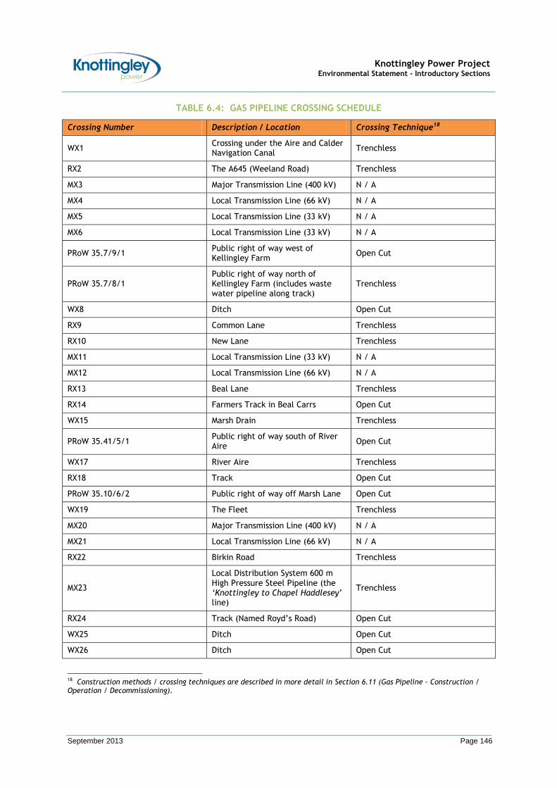
Knottingley Power Project Environmental Statement - Introductory Sections
September 2013 Page 146
TABLE 6.4: GAS PIPELINE CROSSING SCHEDULE
Crossing Number Description / Location Crossing Technique18
WX1 Crossing under the Aire and Calder Navigation Canal
Trenchless
RX2 The A645 (Weeland Road) Trenchless
MX3 Major Transmission Line (400 kV) N / A
MX4 Local Transmission Line (66 kV) N / A
MX5 Local Transmission Line (33 kV) N / A
MX6 Local Transmission Line (33 kV) N / A
PRoW 35.7/9/1 Public right of way west of Kellingley Farm
Open Cut
PRoW 35.7/8/1 Public right of way north of Kellingley Farm (includes waste water pipeline along track)
Trenchless
WX8 Ditch Open Cut
RX9 Common Lane Trenchless
RX10 New Lane Trenchless
MX11 Local Transmission Line (33 kV) N / A
MX12 Local Transmission Line (66 kV) N / A
RX13 Beal Lane Trenchless
RX14 Farmers Track in Beal Carrs Open Cut
WX15 Marsh Drain Trenchless
PRoW 35.41/5/1 Public right of way south of River Aire
Open Cut
WX17 River Aire Trenchless
RX18 Track Open Cut
PRoW 35.10/6/2 Public right of way off Marsh Lane Open Cut
WX19 The Fleet Trenchless
MX20 Major Transmission Line (400 kV) N / A
MX21 Local Transmission Line (66 kV) N / A
RX22 Birkin Road Trenchless
MX23
Local Distribution System 600 m High Pressure Steel Pipeline (the ‘Knottingley to Chapel Haddlesey’ line)
Trenchless
RX24 Track (Named Royd’s Road) Open Cut
WX25 Ditch Open Cut
WX26 Ditch Open Cut
18 Construction methods / crossing techniques are described in more detail in Section 6.11 (Gas Pipeline – Construction / Operation / Decommissioning).

Knottingley Power Project Environmental Statement - Introductory Sections
September 2013 Page 147
Crossing Number Description / Location Crossing Technique18
RX27 Pale Lane Trenchless
PRoW 35.30/7/1 Public Right of Way north of Pale Lane
Open Cut
6.11 The Gas Pipeline - Construction / Operation / Decommissioning
A Note on Design
6.11.1 The Gas Pipeline will be designed, constructed and tested to comply with Pipeline Design Standard IGE/TD/1.
6.11.2 The Gas Pipeline will be constructed from high-grade welded steel pipe and will be sized up to 600 mm diameter (nominal). The Gas Pipeline will have a Maximum Incidental Pressure of 93.5 bar g and a Maximum Operating Pressure of 85 bar g.
6.11.3 The standard gas pipeline wall thickness will comply with the requirements of the Pipeline Design Standard IGE/TD/1, which defines the minimum safe separation distance between a high pressure gas pipeline and normally inhabited buildings / major roads / major railways. This minimum safe separation distance is known as the Building Proximity Distance (BPD). If normally inhabited buildings / major roads / major railways are closer than 1 BPD (i.e. the gas pipeline is in an area where additional protection is required), thicker wall steel pipe (known as proximity pipe) will be used. The exact locations and lengths of where thicker wall steel pipe will be used will be confirmed throughout the assessment and detailed design stages.
6.11.4 The Gas Pipeline will be buried to a depth of cover which is in accordance with the Pipeline Design Standard IGE/TD/1 and Recognised Industry Standards. For example, depths of cover will be:
No less than 1.1 m in urban and suburban land; and,
No less than 1.2 m under road and watercourse crossings.
6.11.5 It is essential to protect the Gas Pipeline from external corrosion due to biological and chemical activity, or the risk of alternating current (AC) induced corrosion. This is achieved in three ways:
By means of a high integrity anti-corrosion coating applied during manufacture of the pipe, with further coatings applied at the welded joints during pipeline construction;
By installing an impressed cathodic protection (CP) system to supplement the corrosion protection afforded to the Gas Pipeline by the anti-corrosion coating; and
By the installation of an AC corrosion mitigation system to mitigate the risk of AC induced corrosion.
6.11.6 There will be no significant internal corrosion risk since the treated natural gas to be carried is dry and non-corrosive.
6.11.7 In designing the impressed CP system and AC corrosion mitigation system it will be necessary to carry out a Soil Resistivity Survey along the route of the Gas Pipeline to obtain data for design. Other factors that may influence the design and location of the impressed CP system and AC corrosion mitigation system are:

Knottingley Power Project Environmental Statement - Introductory Sections
September 2013 Page 148
Availability of a conveniently located power supply;
The location of any other impressed CP systems in the vicinity of the Gas Pipeline;
The location of other electrically conductive buried systems;
The proximity of larger AC facilities (such as above ground electrical lines / underground electrical cables);
The saturation levels of the soil;
The Gas Pipeline diameter, wall thickness, coating material; and
Identified constraints and the recommendations of this ES.
Construction
6.11.8 A typical construction programme (showing the likely sequence of these typical construction activities) is presented in Figure 6.7.
6.11.9 Following on from mobilisation and pre-construction activities, the main construction activities generally take place between the spring / summer months of March and October. The winter months are normally avoided because the ground conditions are likely to be unsuitable for soil handling and (under wet weather conditions) heavy traffic can damage the sub-soil. However, it is noted that special crossing work (i.e. HDD / Auger Boring) can be carried out during the winter months if suitable all weather condition access can be arranged.
Final Design, Routing and Refinement of the Gas Pipeline
Permanent Rights of Access
6.11.10 Permanent rights of access for the Gas Pipeline will be obtained. This is a necessary requirement in order to gain access for construction of the Gas Pipeline, and also for operation of the Gas Pipeline (i.e. for when KPL need to carry out inspection, maintenance and repairs).
6.11.11 As part of the permanent rights of access, some land-use controls will be necessary to maintain the integrity of the Gas Pipeline.
Final Design, Routing and Refinement of the Gas Pipeline
6.11.12 A Site Investigation Survey will be undertaken before details of the final design, routing and refinement of the Gas Pipeline can be agreed in consultation with relevant bodies.
6.11.13 The Site Investigation Survey work will include geotechnical investigations using Specialist Contractors to drill boreholes and obtain soil samples at pre-identified locations. The geotechnical investigations will be conducted along the proposed Gas Pipeline route and will gather data at all proposed trenchless crossing locations to determine soil classification / strength and confirm the suitability of the proposed trenchless crossing technique.
Mobilisation / Setting up of Main Construction Compound / Pipe Storage Yard
6.11.14 There are two potential locations for the main Construction Compound / Pipe Storage Yard. These are:
Option 1 – At the CCGT power plant site.
Option 2 – At the Euro Auctions Yard, near Eggborough.
6.11.15 The Construction Compound / Pipe Storage Yard would be temporary facility required for the duration of construction. For each Option, the following temporary facilities may be provided:
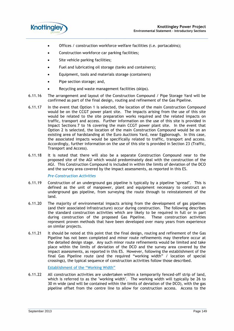
Knottingley Power Project Environmental Statement - Introductory Sections
September 2013 Page 149
Offices / construction workforce welfare facilities (i.e. portacabins);
Construction workforce car parking facilities;
Site vehicle parking facilities;
Fuel and lubricating oil storage (tanks and containers);
Equipment, tools and materials storage (containers)
Pipe section storage; and,
Recycling and waste management facilities (skips).
6.11.16 The arrangement and layout of the Construction Compound / Pipe Storage Yard will be confirmed as part of the final design, routing and refinement of the Gas Pipeline.
6.11.17 In the event that Option 1 is selected, the location of the main Construction Compound would be on the CCGT power plant site. The impacts arising from the use of this site would be related to the site preparation works required and the related impacts on traffic, transport and access. Further information on the use of this site is provided in Impact Sections 7 to 16 covering the main CCGT power plant site. In the event that Option 2 is selected, the location of the main Construction Compound would be on an existing area of hardstanding at the Euro Auctions Yard, near Eggborough. In this case, the associated impacts would be specifically related to traffic, transport and access. Accordingly, further information on the use of this site is provided in Section 23 (Traffic, Transport and Access).
6.11.18 It is noted that there will also be a separate Construction Compound near to the proposed site of the AGI which would predominately deal with the construction of the AGI. This Construction Compound is included in within the limits of deviation of the DCO and the survey area covered by the impact assessments, as reported in this ES.
Pre-Construction Activities
6.11.19 Construction of an underground gas pipeline is typically by a pipeline "spread". This is defined as the unit of manpower, plant and equipment necessary to construct an underground gas pipeline, from surveying the route through to reinstatement of the land.
6.11.20 The majority of environmental impacts arising from the development of gas pipelines (and their associated infrastructure) occur during construction. The following describes the standard construction activities which are likely to be required in full or in part during construction of the proposed Gas Pipeline. These construction activities represent proven methods that have been developed over many years from experience on similar projects.
6.11.21 It should be noted at this point that the final design, routing and refinement of the Gas Pipeline has not been completed and minor route refinements may therefore occur at the detailed design stage. Any such minor route refinements would be limited and take place within the limits of deviation of the DCO and the survey area covered by the impact assessments, as reported in this ES. However, following the establishment of the final Gas Pipeline route (and the required “working width” / location of special crossings), the typical sequence of construction activities follow those described.
Establishment of the “Working Width”
6.11.22 All construction activities are undertaken within a temporarily fenced-off strip of land, which is referred to as the "working width". The working width will typically be 26 to 30 m wide (and will be contained within the limits of deviation of the DCO), with the gas pipeline offset from the centre line to allow for construction access. Access to the
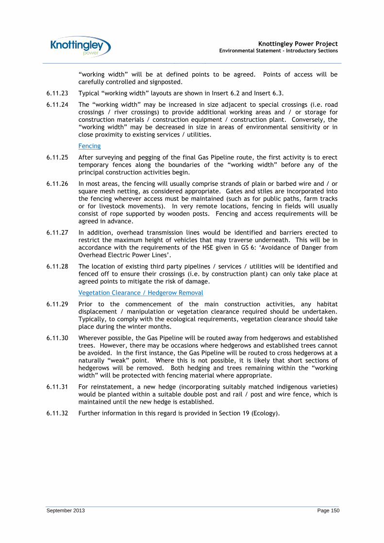
Knottingley Power Project Environmental Statement - Introductory Sections
September 2013 Page 150
“working width” will be at defined points to be agreed. Points of access will be carefully controlled and signposted.
6.11.23 Typical “working width” layouts are shown in Insert 6.2 and Insert 6.3.
6.11.24 The “working width” may be increased in size adjacent to special crossings (i.e. road crossings / river crossings) to provide additional working areas and / or storage for construction materials / construction equipment / construction plant. Conversely, the “working width” may be decreased in size in areas of environmental sensitivity or in close proximity to existing services / utilities.
Fencing
6.11.25 After surveying and pegging of the final Gas Pipeline route, the first activity is to erect temporary fences along the boundaries of the “working width” before any of the principal construction activities begin.
6.11.26 In most areas, the fencing will usually comprise strands of plain or barbed wire and / or square mesh netting, as considered appropriate. Gates and stiles are incorporated into the fencing wherever access must be maintained (such as for public paths, farm tracks or for livestock movements). In very remote locations, fencing in fields will usually consist of rope supported by wooden posts. Fencing and access requirements will be agreed in advance.
6.11.27 In addition, overhead transmission lines would be identified and barriers erected to restrict the maximum height of vehicles that may traverse underneath. This will be in accordance with the requirements of the HSE given in GS 6: ‘Avoidance of Danger from Overhead Electric Power Lines’.
6.11.28 The location of existing third party pipelines / services / utilities will be identified and fenced off to ensure their crossings (i.e. by construction plant) can only take place at agreed points to mitigate the risk of damage.
Vegetation Clearance / Hedgerow Removal
6.11.29 Prior to the commencement of the main construction activities, any habitat displacement / manipulation or vegetation clearance required should be undertaken. Typically, to comply with the ecological requirements, vegetation clearance should take place during the winter months.
6.11.30 Wherever possible, the Gas Pipeline will be routed away from hedgerows and established trees. However, there may be occasions where hedgerows and established trees cannot be avoided. In the first instance, the Gas Pipeline will be routed to cross hedgerows at a naturally “weak” point. Where this is not possible, it is likely that short sections of hedgerows will be removed. Both hedging and trees remaining within the “working width” will be protected with fencing material where appropriate.
6.11.31 For reinstatement, a new hedge (incorporating suitably matched indigenous varieties) would be planted within a suitable double post and rail / post and wire fence, which is maintained until the new hedge is established.
6.11.32 Further information in this regard is provided in Section 19 (Ecology).
Knottingley Power Project Environmental Statement - Introductory Sections
September 2013 Page 151
INSERT 6.2: ILLUSTRATIVE WORKING WIDTH LAYOUT
INSERT 6.3: ILLUSTRATIVE WORKING WIDTH LAYOUT – SPECIAL CROSSING (ROAD CROSSING)

Knottingley Power Project Environmental Statement - Introductory Sections
September 2013 Page 152
Land Drainage Schemes
6.11.33 Wherever appropriate, pre-construction land drainage schemes will be installed to help prevent water logging of the “working width”, and reduce future construction drainage problems. Particular emphasis will be placed on ensuring that existing agricultural land drainage schemes crossed by the route of the Gas Pipeline are maintained and reinstated.
6.11.34 In this regard, at the detailed design stage for the Gas Pipeline, land drainage schemes in each field will be carefully inspected and a record prepared. Wherever necessary, a pre-construction land drainage scheme will be developed. This may entail the installation of new header drains to intercept the existing land drainage which will be cut by the trench of the Gas Pipeline. This serves to maintain the existing land drainage schemes during the construction period whilst minimising the possibility of surface water entering the “working width” area.
6.11.35 Any required land drainage scheme activities within third party pipeline / service / utility wayleaves will only be conducted in accordance with the safe working procedures, which will be agreed in advance of the works.
6.11.36 During construction, all land drains encountered during trench digging operations will be identified and recorded. An appropriate method of permanent reinstatement will be devised and agreed. Where the route of the Gas Pipeline passes under an existing land drain, the usual method of reinstatement is to install a replacement section of land drain with a permanent, rigid support carrying it over the filled-in pipe trench. Where necessary, new lateral and header drains would be laid to new outfalls to replace land drains rendered inoperative by the Gas Pipeline.
6.11.37 All work would be undertaken in line with the requirements of the Land Drainage Act 1991 (as amended).
Construction Activities
Topsoil Stripping
6.11.38 Topsoil would be stripped from within the “working width” and stored at one side to prevent it being mixed with subsoil or being damaged by over-compaction. In instances where the topsoil is particularly shallow, the layer of topsoil and the layer of subsoil immediately below it may be stripped and stored separately.
6.11.39 During topsoil stripping, an archaeological watching brief will be provided in a manner agreed. Further information in this regard is provided in Section 24 (Cultural Heritage / Archaeology).
6.11.40 In areas of environmental sensitivity or very poor soil conditions, topsoil stripping may be omitted in favour of temporary roadways. These roadways will be constructed of a geotextile material and / or hardcore which will be laid over the ground.
Pipe-Stringing
6.11.41 The Gas Pipeline is likely constructed from pre-coated lengths of steel pipe which are 12 m long.
6.11.42 Once required, the steel pipes would be transported from the main Construction Compound / Pipe Storage Yard to the “working width” and laid on wooden sleepers (skids) or cradles along a line parallel to the proposed trench. Insert 6.4 shows steel pipes strung out on wooden skids. Gaps would be left where access across the “working width” is required.

Knottingley Power Project Environmental Statement - Introductory Sections
September 2013 Page 153
6.11.43 Bends would be installed at changes of direction. Where there are sharp changes in direction these will be factory-made (‘hot bends’). Where there are less severe changes in direction these will be field bends (‘cold bends’).
INSERT 6.4: PIPES STRUNG OUT ON WOODEN SKIDS
Welding and Joint Coating
6.11.44 The steel pipes would be welded together to form a continuous steel tube. Each weld will be subjected to Automatic Ultrasonic Testing (AUT) inspection. Any faults detected would be repaired or cut out and replaced and then re-inspected.
6.11.45 Radiographic inspection of a limited number of welds may be required at tie-ins or similar locations where it is not possible to use the AUT inspection technique.
6.11.46 The steel pipes arrive on site with a protective coating already applied, except at their ends. After welding and inspection, the bare metal at the welds / joints would be cleaned and a coating applied to make the pipe coating continuous along its entire length.
6.11.47 The pipe coating would then be tested along the whole of its length to detect any damage or other defects. Any defects would then be repaired and re-tested.
Trenching and Laying
6.11.48 A trench will be excavated to a depth that will allow the pipes to be buried with a minimum cover of 1.1 m (in urban / suburban land). At road / water crossings and other crossings, the depth of cover will be increased. The subsoil from the trench excavation will be separated from the topsoil.
6.11.49 During pipe laying, side boom tractors or equivalent plant are used to lower the pipe into the trench, taking care to avoid damage to the pipe coating. This is shown in Insert 6.5.

Knottingley Power Project Environmental Statement - Introductory Sections
September 2013 Page 154
INSERT 6.5: LOWERING PIPE INTO A PREPARED TRENCH
6.11.50 By utilising standard factory applied pipe coatings (such as 3-layer Polyethylene or Fusion Bonded Epoxy), the pipe will generally have protection from stones and flints. However where field pipe coatings have been applied or aggressive ground conditions have been identified, a bed of sand may be used to provide additional padding and protection to the pipe and applied field pipe coating system.
6.11.51 The trench will then be backfilled with the excavated subsoil. The subsoil is carefully compacted around and over the pipe up to the top of the trench.
Gas Pipeline Commissioning (Cleaning, Gauging, Testing)
6.11.52 A Direct Current Voltage Gradient (DCVG) Survey will be conducted on completion of the installation of the Gas Pipeline to determine if there are any coating defects that need to be exposed to carry out coating repairs.
6.11.53 Following the DCVG Survey, the Gas Pipeline will be cleaned internally using a PIG. The “cleaning PIG” would be ‘launched’ into the Gas Pipeline from the AGI and ‘received’ at the CCGT power plant site. The PIG will be driven through the Gas Pipeline by water or compressed air. A “gauging PIG” can also be used to check the internal diameter of the pipe so as to enable irregularities to be detected and, if necessary, rectified. In addition, a “calliper PIG” can also be used to confirm the pipe geometry, and deem that the pipe dimensions are suitable to accommodate an “intelligent PIG”.
6.11.54 The pipe will be hydrostatically tested by closing off the ends, filling it with water and increasing the pressure to a pre-determined level (higher than the pressure the pipe is designed to operate at). Water used for this purpose will likely be drawn from a suitable local watercourse and will subsequently be discharged in accordance with Environment Agency requirements.
6.11.55 On completion of pressure testing, the pipe will be dried with a combination of “drying PIGs” and clean compressed air to the required dew point.
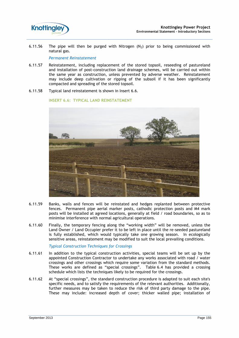
Knottingley Power Project Environmental Statement - Introductory Sections
September 2013 Page 155
6.11.56 The pipe will then be purged with Nitrogen (N2) prior to being commissioned with natural gas.
Permanent Reinstatement
6.11.57 Reinstatement, including replacement of the stored topsoil, reseeding of pastureland and installation of post-construction land drainage schemes, will be carried out within the same year as construction, unless prevented by adverse weather. Reinstatement may include deep cultivation or ripping of the subsoil if it has been significantly compacted and spreading of the stored topsoil.
6.11.58 Typical land reinstatement is shown in Insert 6.6.
INSERT 6.6: TYPICAL LAND REINSTATEMENT
6.11.59 Banks, walls and fences will be reinstated and hedges replanted between protective fences. Permanent pipe aerial marker posts, cathodic protection posts and M4 mark posts will be installed at agreed locations, generally at field / road boundaries, so as to minimise interference with normal agricultural operations.
6.11.60 Finally, the temporary fencing along the “working width” will be removed, unless the Land Owner / Land Occupier prefer it to be left in place until the re-seeded pastureland is fully established, which would typically take one growing season. In ecologically sensitive areas, reinstatement may be modified to suit the local prevailing conditions.
Typical Construction Techniques for Crossings
6.11.61 In addition to the typical construction activities, special teams will be set up by the appointed Construction Contractor to undertake any works associated with road / water crossings and other crossings which require some variation from the standard methods. These works are defined as “special crossings”. Table 6.4 has provided a crossing schedule which lists the techniques likely to be required for the crossings.
6.11.62 At “special crossings”, the standard construction procedure is adapted to suit each site's specific needs, and to satisfy the requirements of the relevant authorities. Additionally, further measures may be taken to reduce the risk of third party damage to the pipe. These may include: increased depth of cover; thicker walled pipe; installation of

Knottingley Power Project Environmental Statement - Introductory Sections
September 2013 Page 156
pipeline warning tape; concrete slab placement above the gas pipeline; and, screw anchors or concrete weight coating applied to the pipe.
Open Cut – Private Roads / Tracks / Ditches
6.11.63 For private roads / tracks / ditches, an open cut construction technique would likely be used. For open cut construction techniques, a trench is dug directly across the private road / track / ditch. Once dug, a short section of pipe is installed and the trench backfilled with the graded excavated material.
6.11.64 In the case of ditches, the pipe will be installed at the depth required by the Pipeline Design Standard IGE/TD/1, and protective concrete slabs will be installed if the crossing technique permits this.
6.11.65 The surface of the private road / track / ditch will then be reinstated with appropriate material.
Auger Boring
6.11.66 The auger boring method is shown in Insert 6.7. Auger boring is a relatively simple trenchless technique that limits surface disturbance, and therefore this method is likely to be used where the disturbance caused by a crossing by an open cut techniques may be regarded as unacceptable. Auger boring may also be used at some watercourse and third party pipelines / services / utilities crossings.
INSERT 6.7: AUGER BORING AT A ROAD CROSSING
6.11.67 During auger boring two drilling pits are dug, one at either end of the crossing section. The sides of the pits will be either graded with a gentle slope, or, if there is limited space, interlocking sheets and frames may be installed to provide sufficient support to the pit and prevent collapse.
6.11.68 The drilling pit is dug wide enough and long enough to take a set of rails on which the auger boring equipment will run and also accommodate a full length of pipe. Therefore, it would be necessary to increase the “working width” at auger boring crossings in order to store the extra spoil and accommodate the extra plant, vehicles, welfare facilities and other equipment required.
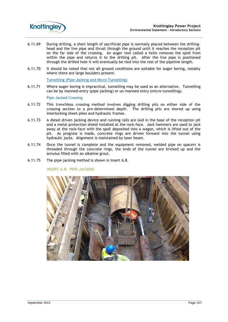
Knottingley Power Project Environmental Statement - Introductory Sections
September 2013 Page 157
6.11.69 During drilling, a short length of sacrificial pipe is normally placed between the drilling-head and the live pipe and thrust through the ground until it reaches the reception pit on the far side of the crossing. An auger tool called a helix removes the spoil from within the pipe and returns it to the drilling pit. After the live pipe is positioned through the drilled hole it will eventually be tied into the rest of the pipeline length.
6.11.70 It should be noted that not all ground conditions are suitable for auger boring, notably where there are large boulders present.
Tunnelling (Pipe-Jacking and Micro-Tunnelling)
6.11.71 Where auger boring is impractical, tunnelling may be used as an alternative. Tunnelling can be by manned-entry (pipe-jacking) or un-manned entry (micro-tunnelling).
Pipe-Jacked Crossing
6.11.72 This trenchless crossing method involves digging drilling pits on either side of the crossing section to a pre-determined depth. The drilling pits are shored up using interlocking sheet-piles and hydraulic frames.
6.11.73 A diesel driven jacking device and running rails are laid in the base of the reception pit and a metal protection shield installed at the rock-face. Jack hammers are used to jack away at the rock-face with the spoil deposited into a wagon, which is lifted out of the pit. As progress is made, concrete rings are driven forward into the tunnel using hydraulic jacks. Alignment is maintained by laser beam.
6.11.74 Once the tunnel is complete and the equipment removed, welded pipe on spacers is threaded through the concrete rings, the ends of the tunnel are bricked up and the annulus filled with an alkaline grout.
6.11.75 The pipe-jacking method is shown in Insert 6.8.
INSERT 6.8: PIPE-JACKING
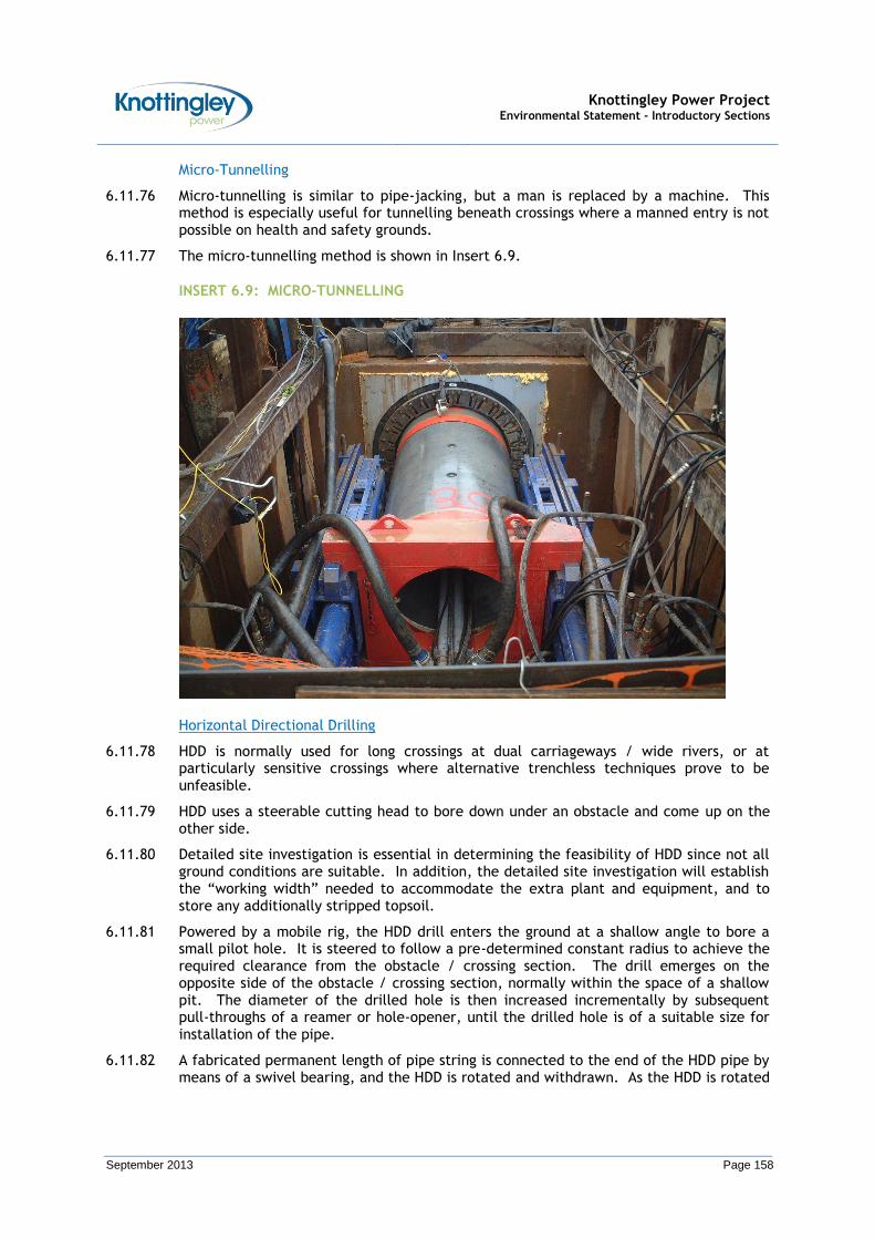
Knottingley Power Project Environmental Statement - Introductory Sections
September 2013 Page 158
Micro-Tunnelling
6.11.76 Micro-tunnelling is similar to pipe-jacking, but a man is replaced by a machine. This method is especially useful for tunnelling beneath crossings where a manned entry is not possible on health and safety grounds.
6.11.77 The micro-tunnelling method is shown in Insert 6.9.
INSERT 6.9: MICRO-TUNNELLING
Horizontal Directional Drilling
6.11.78 HDD is normally used for long crossings at dual carriageways / wide rivers, or at particularly sensitive crossings where alternative trenchless techniques prove to be unfeasible.
6.11.79 HDD uses a steerable cutting head to bore down under an obstacle and come up on the other side.
6.11.80 Detailed site investigation is essential in determining the feasibility of HDD since not all ground conditions are suitable. In addition, the detailed site investigation will establish the “working width” needed to accommodate the extra plant and equipment, and to store any additionally stripped topsoil.
6.11.81 Powered by a mobile rig, the HDD drill enters the ground at a shallow angle to bore a small pilot hole. It is steered to follow a pre-determined constant radius to achieve the required clearance from the obstacle / crossing section. The drill emerges on the opposite side of the obstacle / crossing section, normally within the space of a shallow pit. The diameter of the drilled hole is then increased incrementally by subsequent pull-throughs of a reamer or hole-opener, until the drilled hole is of a suitable size for installation of the pipe.
6.11.82 A fabricated permanent length of pipe string is connected to the end of the HDD pipe by means of a swivel bearing, and the HDD is rotated and withdrawn. As the HDD is rotated

Knottingley Power Project Environmental Statement - Introductory Sections
September 2013 Page 159
and withdrawn it pulls the pipe string into position behind it. This part of the pipe is later tied into the remainder of the pipeline length.
6.11.83 Bentonite, a naturally occurring fine clay, is normally used as a drilling lubricant. It is pumped from tanks to the head of the HDD drilling bit through the centre of the hollow drill pipe. The lubricant mixes with the drillings, which are forced back along the hole under pressure, and into a recycling plant. This recovers much of the bentonite.
6.11.84 The HDD technique is shown in Insert 6.10.
INSERT 6.10: HDD RIG PULLING BACK THE PIPE-STRING
Techniques for Crossing Existing Third Party Pipelines / Services / Utilities
6.11.85 Prior to commencement of the detailed design, a search for existing third party pipelines / services / utilities will be conducted to identify any known and unknown third party pipelines / services / utility along the route of the Gas Pipeline. This search will be in addition to that undertaken at the pre-application stage, and will be aimed at verifying the nature of the third party pipelines / services / utilities and the associated Owners / Operators.
6.11.86 Following this, the Owners / Operators of the third party pipelines / services / utilities will be contacted to establish:
Any requirements for work within their wayleave;
Any special precautions that may be required to avoid damage to pipelines / services / utilities; and
Any special requirement for the design of the pipelines / services / utilities crossing.
6.11.87 Furthermore, crossings of third party pipelines / services / utilities by construction traffic (comprising construction plant, equipment and personnel) will only take place at locations agreed with the associated Owners / Operators.
6.11.88 The crossings by construction traffic will be specifically designed to mitigate damage (i.e. the use of bog mats to reduce the load on third party structures from construction

Knottingley Power Project Environmental Statement - Introductory Sections
September 2013 Page 160
traffic). In addition, fences will be erected at third party pipeline / service / utility crossing points to ensure that construction traffic can only cross at specified points.
6.11.89 The selected crossing techniques will aim to minimise both the risk of damage and level of any risk to any third party pipeline / service / utility.
6.11.90 Flowchart 6.1 details the design of third party pipeline / service / utility crossings.
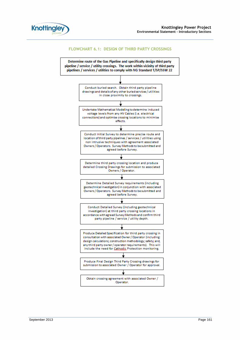
Knottingley Power Project Environmental Statement - Introductory Sections
September 2013 Page 161
FLOWCHART 6.1: DESIGN OF THIRD PARTY CROSSINGS
Knottingley Power Project Environmental Statement - Introductory Sections
September 2013 Page 162
6.11.91 Following detailed design but prior to construction work commencing, the existing third party pipelines / services / utilities crossed by the Gas Pipeline will be accurately located by trial pit excavation and / or by an indirect location method. Any work to locate third party pipelines / services / utilities will be carried out in conjunction with associated Owner’s / Operator’s requirements.
6.11.92 The third party crossing methods selected will minimise the risk of damage to third party pipelines / services / utilities both during the construction phase and during future operation of the Gas Pipeline. Wherever necessary, trenchless crossing techniques will be employed to minimise the risk of damage and any associated environmental impact.
6.11.93 All the above work will be carried under the guidance and supervision of the responsible Service Authorities' Inspectors, as required. Flowchart 6.2 summarises the process.
6.11.94 The requirements for third party crossings will follow the Guidelines given in HSG 47 “Avoiding Danger from Underground Services” and National Grid Standard T/SP/SSW/22 “Safe Working in the Vicinity of National Grid High Pressure Gas Pipelines – Requirements for Third Parties.
6.11.95 Construction activities in the vicinity of overhead transmission lines will follow the guidelines given in HSE Guidance document GS6 “Avoidance of Danger from Overhead Powerlines”. Additionally, where trenchless techniques are to be used, reference will be made to “Trenchless Techniques” (IGEM/SR/28 Edition 2) published by the Institute of Gas Engineers and Managers (2011).
6.11.96 In following these guidelines, together with the other procedures set out in this Section, existing pipelines / services / utilities along the route of the Gas Pipeline will be identified along with their location and no physical works will be carried out in relation to the Gas Pipeline without the prior agreement of the associated Owner / Operator (e.g. agreed Risk Assessments and Method Statements).

Knottingley Power Project Environmental Statement - Introductory Sections
September 2013 Page 163
FLOWCHART 6.2: CONSTRUCTION OF THIRD PARTY CROSSINGS

Knottingley Power Project Environmental Statement - Introductory Sections
September 2013 Page 164
ACCOMPANYING NOTES TO FLOWCHART 6.2
Flowchart Note 1: Prior to any construction activities, a final HAZOP and HAZCON of the proposed design of the Gas Pipeline at the third party crossings will be conducted by the Construction Contractor in conjunction with the Pipeline Designer. The design drawings, third party Owner / Operator requirements, crossing methodology and any Method Statements or Risk Assessments already agreed will be reviewed. It is essential that open conversation between the Construction Contractor and the third party Owner / Operator is undertaken at this stage to determine the specific requirements for the proposed third party crossing. The third party Owner / Operator will be invited to attend the review.
Flowchart Note 2: The Construction Contractor will finalise their Method Statements and Risk Assessments for completing the crossing of any third party pipelines / services / utilities. The Method Statements and Risk Assessments will be based upon the crossing technique that has been adopted / selected as part of the detailed design. The final Method Statements and Risk Assessments will be issued for review and comment. Comments will be incorporated in to the Method Statements and Risk Assessments and the documents will be issued.
Flowchart Note 3: The Construction Contractor will meet with the Owner / Operator to: agree any specific safe working requirements; agree any third party Owner / Operator supervision / surveillance requirements; and be provided with a copy of the Safe Working Practices that the third party Owner / Operator will require for the third party crossing construction work. The Safe Working Practices will follow the minimum requirements given in NG Standard T/SP/SSW/22.
Flowchart Note 4: If no identification already exists, third party pipelines / services / utilities will be marked / identified. Protective matting will be installed at the “working width” to ensure that construction traffic (comprising plant and equipment) only crosses the third party pipeline / service / utility at agreed and defined locations. Fences will be erected each side of the reinforced crossing to ensure that only the designated crossing point can be used by construction traffic.
Flowchart Note 5: Third party Owners / Operators may have specific requirements for vibration or other monitoring on their pipeline / service / utility at the crossing point. If required, monitoring access points to the third party crossing will be constructed and the specified monitoring system installed. All work will be carried out in accordance with third party Owner / Operator requirements. No construction activities will commence until the monitoring system is installed.
Flowchart Note 6: The third party Owner / Operator will be notified prior to the commencement of any construction activities so that they can arrange for any supervision / surveillance of the construction works. Once the third party Owner / Operator is satisfied, construction works will commence. The third party Owner / Operator will be allowed access to the construction works, including their pipeline / service / utility, at their crossing points.
Flowchart Note 7: The trenchless third party crossing access points each side of the third party crossing will be constructed in accordance with the agreed Method Statements for the crossing technique adopted / selected. The Gas Pipeline sections will be moved into position, fabricated and inspected to confirm Gas Pipeline the design requirements. The installation of the Gas Pipeline at the third party crossing will commence and measures will be taken to ensure that the Gas Pipeline is at the required depth at the third party crossing point.
Flowchart Note 8: Once the third party crossing has been completed, ‘As Built’ Drawings of the third party crossing will be prepared. These will include the precise location and depth of the Gas Pipeline and the third party pipeline / service / utility. Pipeline coating integrity checks will be performed.
Flowchart Note 9: At the third party crossing point, the Gas Pipeline will be tied into the remainder of the pipeline length. The area at the third party crossing point will be reinstated. Once it is clear that no further construction traffic (comprising plant and equipment) will cross the third party crossing point, then the temporary fencing and protective matting will be removed.
Knottingley Power Project Environmental Statement - Introductory Sections
September 2013 Page 165
Pre-Commissioning / Commissioning
6.11.97 Following construction (but before commercial operation), a pre-commissioning and commissioning testing will be undertaken.
6.11.98 During pre-commissioning, the Gas Pipeline will be filled with water to hydrostatically test it. This testing will be done in stages and will comply with the Health and Safety Executive requirements. During commissioning, the Gas Pipeline will be filled with natural gas ready for commercial operation.
6.11.99 In addition, an impressed CP system survey will be carried out (and repeated at regular intervals during the lifetime of the Gas Pipeline as a continuing check on its condition). In the event that the levels identified in the impressed CP system survey are not to the required levels, then remedial work will be implemented. Test Posts for the impressed CP system will be installed at intervals of about 1 km along the proposed Gas Pipeline route, normally beside road crossings for ease of access.
6.11.100 It should be noted that there are limited potential environmental impacts associated with pre-commissioning / commissioning, and therefore some Impact Assessments may omit this stage.
Operation and Maintenance
6.11.101 After full commissioning of the Gas Pipeline, it will be operated and maintained in such a manner as to keep it safe and in good condition. Indeed, the design of the Gas Pipeline, together with regular inspection and monitoring, will ensure that any risks to the Gas Pipeline are virtually eliminated.
Routine Operation
6.11.102 The purpose of the Gas Pipeline is to allow the CCGT power plant to be fuelled by a supply of natural gas. Accordingly, the Gas Pipeline will be designed to carry non-odorised natural gas, and no loss of natural gas to the surrounding environment is anticipated.
6.11.103 Operation procedures will be agreed with the Health and Safety Executive, and implemented. As part of these procedures, an Emergency Plan will be prepared, in accordance with the Pipelines Safety Regulations 1996, to cover contingency plans and remedial measures. The Emergency Plan will be completed in consultation with the Local Authority. In addition, a Major Accident Prevention Document (MAPD) shall be prepared, which shall detail the risks associated with the operation of the Gas Pipeline and describe how the risks would be mitigated during its operational lifetime. The MAPD would be updated as often as deemed necessary during the operational lifetime of the Gas Pipeline.
6.11.104 The Gas Pipeline will be controlled and monitored from the CCGT power plant site. To enable the monitoring and control of the Gas Pipeline and AGI, control cables between the CCGT power plant site and the AGI will be installed with the Gas Pipeline.
Routine Inspection
6.11.105 The inspection of the Gas Pipeline will be carried out in accordance with the requirements of the Pipeline Design Standard IGE/TD/1.
6.11.106 Inspection is normally carried out in the following ways:
Periodic Visual Inspection
A “Care and Maintenance” Team will carry out visual inspection. Their duties will include regular vantage point surveillance by road and foot. Their observations will provide a record of changing ground conditions and third party activity along
Knottingley Power Project Environmental Statement - Introductory Sections
September 2013 Page 166
the route of the Gas Pipeline and prevent any unauthorised third party activity from compromising its safety.
PIG Survey
An “intelligent PIG” survey will also be carried out post-construction. The “intelligent PIG” survey will be carried out within a reasonable period of time after commercial operation of the Gas Pipeline. The “intelligent PIG” survey can only be carried out when there is gas flow in the Gas Pipeline “Intelligent PIG” survey will be part of the standard inspection procedure of the Gas Pipeline.
The Gas Pipeline will thereafter be subjected to “intelligent PIG” survey at approximately 5 yearly intervals, unless it is otherwise confirmed that the inspection interval can be increased.
CP System Monitoring
6.11.107 Furthermore, it is likely that helicopter fly-overs will be required to inspect the route of the Gas Pipeline. These helicopter fly-overs would be infrequent events. The helicopter fly-overs are aided by the presence of aerial pipeline markers along the ground.
Routine Maintenance
6.11.108 Routine maintenance will predominately be confined to the AGI, and will comprise: inspection; testing; and, calibration.
6.11.109 Along the route of the Gas Pipeline, the test posts for the CP system will be visited at least every 6 months so that the level of CP on the Gas Pipeline can be monitored. All marker posts / posts will be maintained and vegetation controlled to enable the marker posts / posts to be clearly visible.
Repairs
6.11.110 In the event that defects are found along the Gas Pipeline, it may be necessary to carry out excavations, further testing and possibly repairs. However, it should be noted that repairs are extremely infrequent events given the standards that are applied to the Gas Pipeline at the time of design / construction / pre-commissioning / commissioning.
6.11.111 Repairs usually involve isolated excavations. The working area to be taken would be dependent upon the length of Gas Pipeline to be exposed, and also the depth of the Gas Pipeline. The working area would be fenced off, and top-soil stripped to one side. The Gas Pipeline would then be carefully exposed and excavated. Following repair, the Gas Pipeline would be replaced.
6.11.112 In advance of any repairs, KPL would carry out an environmental review of the proposed working area in order to identify any potential environmental impacts, and implement appropriate mitigation and monitoring measures.
Decommissioning
6.11.113 A modern pipeline, if properly maintained, should remain fit for purpose almost indefinitely.
6.11.114 However, at the end of the useful life of the CCGT power plant, the Gas Pipeline will be decommissioned. At that time detailed decommissioning procedures will be produced in line with prevailing best practice. Based on current best practice, the Gas Pipeline will be left in place and stabilised. The Gas Pipeline would be filled with an inert gas, usually nitrogen. The pressure of the Gas Pipeline would be monitored, and the external corrosion systems would be maintained.
6.11.115 At the final ‘end of life’ of the Gas Pipeline, procedures will be produced, in line with prevailing best practice, to ensure that the Gas Pipeline does not become a hazard.

Knottingley Power Project Environmental Statement - Introductory Sections
September 2013 Page 167
Based on current best practice, the Gas Pipeline will be left in place and stabilised. The Gas Pipeline would be filled with slurry cement grout.
6.12 The Gas Pipeline – Safety Considerations
Introduction
6.12.1 Safety is of fundamental importance during every stage of the planning, routing, design, construction and subsequent operation of a high pressure gas pipeline. This Section provides a brief description of the appropriate safety considerations to ensure compliance with the requirements of the HSE and ensure the safe operation of the Gas Pipeline.
6.12.2 KPL will only select gas pipeline construction contractors with detailed experience of the design and construction of gas pipelines to UK Gas Industry Codes and Standards. The selection process will use safety as one of the main criteria to pre-qualify suitable gas pipeline construction contractors for the development of the Gas Pipeline.
Pipeline Routing and Design Criteria
6.12.3 Safety is one of the key factors considered in the choice of route for a gas pipeline. From an operational point of view it is clearly important that the gas pipeline is designed, built and tested in such a way that its integrity is not compromised during its life time. The objective is to ensure that if a failure were to occur then the consequences would be within set parameters which the HSE define in its "broadly acceptable category".
6.12.4 The HSE have been notified about the proposed Gas Pipeline, and will be issued with a list of technical data, and a Safety Evaluation Report if deemed necessary.
6.12.5 The Gas Pipeline will be designed and constructed in accordance with the latest editions of the following principal Codes of Practice, Standards, Recommendations, and Statutory Legislation, where appropriate:
Institute of Gas Engineers’ (IGE) Recommendations on Transmission and Distribution Practice – IGE/TD/1: Edition 5, 2009 - Steel Pipelines and Associated Installations for High Pressure Gas Transmission19 (Pipeline Design Standard IGE/TD/1);
The Pipelines Safety Regulations, 1996;
The Pressure Systems Safety Regulations, 2000;
The Construction (Design and Management) Regulations, 2007;
The Construction (Health, Safety and Welfare) Regulations, 1996;
The Gas Safety Management Regulations, 1996;
The Provision of Use and Work Equipment Regulations, 1998;
Control of Substances Hazardous to Health Regulations (COSHH), 2002;
Dangerous Substances and Explosive Atmosphere Regulations (2002);
The Noise at Work Regulations, 1989;
Manual Handling – Guidance on Regulations 1992;
Institution of Gas Engineers Code IGE/TD/13: Off-takes and pressure-regulating installations for inlet pressures between 7 and 100 bar; and
19 This is the code to which the majority of the UK’s high pressure gas pipelines are designed, built and operated.
Knottingley Power Project Environmental Statement - Introductory Sections
September 2013 Page 168
American Society of Mechanical Engineers (ASME) B 31.3: Process Piping.
6.12.6 All measures will be taken to ensure the long-term safety of the Gas Pipeline. During manufacture all components will be subjected to rigorous inspection and testing before being certified fit for use and incorporated. At road, rail and watercourse crossings and any other areas where additional protection might be required, heavier walled pipe will be installed.
6.12.7 A Formal Process Safety Assessment shall be conducted at relevant times during the design of the gas pipeline system. Hazard Identification (HAZID), Hazardous Construction (HAZCON), and Hazards and Operability (HAZOP) Studies shall be conducted to ensure that all hazards in the design, construction and operation of the gas pipeline system are identified and mitigated.
6.12.8 A Designers Risk Register shall be maintained during the design and development of the Gas Pipeline to document and monitor all risks which have been highlighted throughout the Gas Pipeline lifecycle. The Designers Risk Register shall be considered to be a ‘live’ document and all risks discussed within it should be considered during the design of the Gas Pipeline.
6.12.9 The construction of the Gas Pipeline will be carried out to comply with the requirements of the Construction (Design and Management) Regulations 2007. Safe working practices will be developed for all aspects of construction. In addition, a detailed Project Safety Plan will be developed and maintained as a ‘live’ document to ensure safety during construction and testing.
6.12.10 As part of the initial Outline Design of the gas pipeline system a Population Density Survey has been carried out in accordance with the requirements of Pipeline Design Standard IGE/TD/1. The Population Density Survey demonstrates that the route of the Gas Pipeline will be classed as a Type ‘R’ and there will be minimal Type ‘S’ area excursions. A detailed Population Density Survey shall be carried out as part of the detailed design, utilising the latest information from census and route surveys once the detailed design has finalised the route of the Gas Pipeline.
6.12.11 Typical safety measures employed during and after construction of a gas pipeline and AGI consist of the following:
100 per cent AUT inspection or radiographic inspection of all field welds (or other approved techniques);
100 per cent visual and Non-Destructive Testing (NDT) inspection of all welds;
100 per cent coating holiday detection to ensure the integrity of the pipeline coating systems;
100 per cent inspection of all pipe lowering and backfill operations;
Hydrostatic pressure testing of the completed pipeline to comply with the requirements of Pipeline Design Standard IGE/TD/1 (in the case of this Gas Pipeline the minimum test pressure has been calculated to be 128 bar g, which is 1.5 times the Maximum Operating Pressure of 85 bar g);
The use of ‘pigging’ operations to ensure that the Gas Pipeline dimensions are correct and that there are no dents or defects in the Gas Pipeline; and
The installation of an impressed current CP system and AC corrosion mitigation system (if required) which, together with the factory and site-applied anti-corrosion pipe coatings, will minimise the potential for external corrosion of the Gas Pipeline.
Knottingley Power Project Environmental Statement - Introductory Sections
September 2013 Page 169
6.12.12 During the operational life of the gas pipeline system, routine maintenance will be carried out to ensure its continued fitness for purpose and continued compliance with the requirements of Pipeline Design Standard IGE/TD/1 and the relevant Statutory Legislation. Typical maintenance measures will consist of:
Routine pipe to soil potential checks to ensure the impressed current CP system, which prevents external corrosion, is operating satisfactorily;
Routine inspection of the AC corrosion mitigation system to ensure it is operating satisfactorily;
Frequent routine surveillance of the route of the Gas Pipeline to mitigate the risk of inadvertent damage from third parties;
Close Interval Potential surveys to verify the effectiveness of the current CP system / AC corrosion mitigation system / pipe coatings and confirm the absence of pipe coating defects;
DCVG Survey along the entire route of the Gas Pipeline to identify areas of pipe coating defects (if any);
An “Intelligent PIG” run, with an initial baseline run within a reasonable period of time following the commercial operation of the CCGT power plant followed by “intelligent PIG” inspection at 5 yearly intervals, unless it is otherwise confirmed that the inspection interval can be increased;
Inclusion of the route of the Gas Pipeline in the National Linesearch Database so that all Third Party Utilities who use the Database will know of its existence;
Installation of aerial markers and M4 markers at all field boundaries;
Routine maintenance at the AGI; and
The installation of CCTV and intruder detection alarms at the AGI.
6.12.13 These measures are designed to ensure the Gas Pipeline is designed, built and maintained to the highest of standards. This will afford a safe and efficient means of meeting the requirements of transporting natural gas safely from the existing National Transmission System (Number 29 Feeder) to the CCGT power plant site.
6.12.14 The Emergency Plan for the Gas Pipeline will be prepared in accordance with the requirements of the Pipelines Safety Regulations 1996 by the Local Authority with the assistance of KPL. The Emergency Plan will detail all the measures to be followed in the event of an emergency on the gas pipeline system.
6.12.15 In accordance with the requirements of the Gas Safety (Management) Regulations 1996, KPL (as a conveyor of natural gas), will either submit a Safety Case or apply for an exemption under the regulations. Key duties will include the nomination of a Network Emergency Co-ordinator who will initially deal with any public reported gas escapes and gas incidents along the Gas Pipeline route.
6.12.16 In addition, a MAPD shall be prepared in accordance with the requirements of the Pipeline Safety Regulations 1996, which shall detail the risks associated with the operation of the Gas Pipeline and describe how the risks will be mitigated during its operational lifetime. The MAPD will be updated as often as deemed necessary during the operational lifetime of the Gas Pipeline.
6.12.17 In summary, the gas pipeline system would be operated and maintained to meet the requirements of the Pipeline Design Standard IGE/TD/1 and the Pipelines Safety Regulations 1996, with the pressure pipe work within the overall AGI operated and

Knottingley Power Project Environmental Statement - Introductory Sections
September 2013 Page 170
maintained to meet the requirements of the Pressure Systems Safety Regulations 2000 and the requirements of IGE/TD/13.
6.12.18 As a result of the inherent in-built safety measures aforementioned, the Gas Pipeline will provide an acceptably safe means of transporting gas to the CCGT power plant site.
6.13 Other Consents / Permits / Licences Required for the KPP
6.13.1 In addition to the DCO, there are several other consents, permits and licences which may be required to enable the KPP to be constructed, operated and decommissioned. It is envisaged that these other consents, permits and licences will be obtained during the post-DCO / pre-construction stage.
6.13.2 Whilst a number of these other consents, permits and licences could be included in the application for a DCO (i.e. through the use of additional clauses), the other consents, permits and licences mainly related to the control and regulation of construction, and are normally obtained during the pre-construction stage (i.e. after the final detailed design has been completed and the construction methodologies have been finalised).
6.13.3 Accordingly, KPL believe that it is more appropriate to obtain these other consents, permits and licences during later stages of the KPP.
6.13.4 The key other consents / permits / licences required under other legislation potentially required by the KPP are provided in the DCO application document, List of Consents and Documents Required under other Legislation, PINS Application Document Reference (APFP 5(2)(q)).