Entwurf Newsletter Inform 1 2013 7.8.13
12
InForm Edition 1/2013 Newsletter of the Institute for Combustion Engines 2013, VKA / RWTH Aachen University 1 CURRENT ISSUES Center for Mobile Propulsion (CMP) The inauguration of the "Center for Mobile Propulsion" at RWTH Aachen University will mark a further milestone in Aachen's history of high-quality research centers. Lead by the Institute for Combustion Engines (VKA), 16 institutes joined forces to investigate and optimize electrified mobile powertrains in an interdisciplinary approach. Figure 1: Institute for Combustion Engines (left) and Center for Mobile Propulsion (right) The upcoming worldwide changes in energy production and distribution will have an impact on the mobile sector. Fossil energy resources are limited and thus will become more expensive within the next years. Simultaneously, the share of energy produced by renewable resources rises. Both effects inevitably lead to an increase of the share of electrical energy in the society's energy mix. New technical developments in mobile propulsion, especially hybrid and battery technology, and widen the development of propulsion systems to an integrated research field of numerous different disciplines. Tasks concerning the research of new powertrains hence become constantly more complex and therefore require interdisciplinary cooperation. The interdisciplinary approach chosen for the es- tablishment of the Center for Mobile Propulsion is also reflected in the experimental instrumentation of the research center: Within the CMP, compo- nent test benches for batteries, electric motors, transmissions, combustion engines and power- trains are installed. Figure 2: Flexibly designed test benches (left) and powertrain test bench (right) By focusing all these test benches at one facility, real-time communication between the different component test benches is enabled (via network). The integration of a simulator facilitates to simulate a systematic behavior of early stage components. Thereby, virtual powertrains can be outlined independently from individual setups. By this, researchers can examine interactions of single components in dynamic use, consider the effects of different topologies and explore necessary control strategies of the overall system in an early project phase. Moreover, the test laboratory has an integrated workshop to conduct setups and alterations on-site. The test benches are designed highly flexible for time saving and an effective use. In October 2013, the research training group “Integrated Energy Supply Modules for On-Road Electric Mobility”, funded by German Research Foundation, will start working at the CMP. With the establishment of the CMP, interdisciplinary competences concerning the increasingly more complex propulsion technology for automobiles are brought together. Current Issues 1-2 Research & Technology 3-11 Events 12 Imprint 12 Dipl.-Ing. Thomas Huth Phone: +49 241 80 95355 [email protected]
Transcript of Entwurf Newsletter Inform 1 2013 7.8.13

InForm
Edition 1/2013 Newsletter of the Institute for Combustion Engines
2013, VKA / RWTH Aachen University 1
C U R R E N T I S S U E S
Center for Mobile Propulsion (CMP) The inauguration of the "Center for Mobile Propulsion" at RWTH Aachen University will mark a further milestone in Aachen's history of high-quality research centers. Lead by the Institute for Combustion Engines (VKA), 16 institutes joined forces to investigate and optimize electrified mobile powertrains in an interdisciplinary approach.
Figure 1: Institute for Combustion Engines (left) and
Center for Mobile Propulsion (right)
The upcoming worldwide changes in energy production and distribution will have an impact on the mobile sector. Fossil energy resources are limited and thus will become more expensive within the next years. Simultaneously, the share of energy produced by renewable resources rises. Both effects inevitably lead to an increase of the share of electrical energy in the society's energy mix. New technical developments in mobile propulsion, especially hybrid and battery technology, and widen the development of propulsion systems to an integrated research field of numerous different disciplines. Tasks concerning the research of new powertrains hence become constantly more complex and therefore require interdisciplinary cooperation.
The interdisciplinary approach chosen for the es-tablishment of the Center for Mobile Propulsion is also reflected in the experimental instrumentation of the research center: Within the CMP, compo-nent test benches for batteries, electric motors, transmissions, combustion engines and power-trains are installed.
Figure 2: Flexibly designed test benches (left) and
powertrain test bench (right)
By focusing all these test benches at one facility, real-time communication between the different component test benches is enabled (via network). The integration of a simulator facilitates to simulate a systematic behavior of early stage components. Thereby, virtual powertrains can be outlined independently from individual setups. By this, researchers can examine interactions of single components in dynamic use, consider the effects of different topologies and explore necessary control strategies of the overall system in an early project phase. Moreover, the test laboratory has an integrated workshop to conduct setups and alterations on-site. The test benches are designed highly flexible for time saving and an effective use.
In October 2013, the research training group “Integrated Energy Supply Modules for On-Road Electric Mobility”, funded by German Research Foundation, will start working at the CMP. With the establishment of the CMP, interdisciplinary competences concerning the increasingly more complex propulsion technology for automobiles are brought together.
Current Issues 1-2Research & Technology 3-11Events 12Imprint 12
Dipl.-Ing. Thomas Huth
Phone: +49 241 80 95355 [email protected]

Newsletter of the Institute for Combustion Engines, Edition 1/2013
2 2013, VKA / RWTH Aachen University
Ground-Breaking for the Expansion of Aldenhoven Testing Center With the ground-breaking ceremony on April 10th, 2013, the second construction phase of the Aldenhoven Testing Center on the former Emil Mayrisch coal mine has started. After an extensive phase of planning, five new circuits and tracks are under construction now: an oval circuit, a rough road track, a braking track, a 2000 m handling course, and a climbing hill.
All facilities will be available for the research activi-ties at the Institute for Combustion Engines (VKA).
Figure 1: Ground-breaking ceremony at ATC
The costs for the second construction phase are about 9.5 million euros, 80 percent of which are provided by the Federal State of NRW. According to the ATC management, the testing center is ex-ceptional in that “it is open for use by small and medium-sized enterprises who seek to conduct mobility research projects that require a testing site.”
The testing center covers various purposes. Cur-rent research projects aim to develop and test modern driving assistance systems or are for ex-ample concerned with possibilities to lower ex-haust emissions or to reduce the fuel consumption of combustion engines. Hybrid propulsion and fuel cell systems are further research topics. The new test tracks with special surfaces, obstacles, water-ing systems, different bend radiuses and further facilities will allow testing research vehicles and driver assistance systems under real-world condi-tions without hindering real traffic.
Dr.-Ing. Martin Nijs
Phone: +49 241 80 95370 [email protected] www.atc-aldenhoven.de
The Profile Area Energy, Chemical & Process Engineering The provision of sustainable energy and materials is clearly one of the major global challenges which were identified in the future strategy of RWTH Aa-chen University. The profile area Energy, Chemi-cal & Process Engineering (ECPE) addresses the two most important pathways to achieve this goal: improvements in energy and material efficiency and the transition to renewable sources. Without doubt, there is still a significant potential for im-provements in established technologies for energy and materials conversion and usage which has to be opened up. Breakthrough innovations, howev-er, increasingly require expanding the classical scope of energy and chemical engineering to inte-grate novel insights from the molecular sciences.
Based upon this common root, the existing division between the energy and chemical disciplines has to be overcome, since an energy- and material-efficient society will be built upon integrated pro-cessing and recycling strategies. A Steering Committee consisting of its spokesman professor Stefan Pischinger and professors Rik De Doncker, Peter Kukla, Reinhard Madlener, Albert Moser, Matthias Wessling and Regina Palkovits from five different RWTH Aachen University faculties as well as professor Detlef Stolten from For-schungszentrum Jülich leads the profile area ECPE.
First, core topics and a research roadmap will be developed interdisciplinarily. Professor Pischinger identifies the support of research cooperations between institutes and faculties as main focus for the work of the Steering Committee.
The illustration shows centers, I3s and the cluster of excellence “Tailor-Made Fuels from Biomass”, in which interdisciplinary research in the field of ECPE is performed.
Figure 1: Centers, I³s and “TMFB”
Dipl.-Ing. Daniel Henaux
Phone: +49 241 80 95350 [email protected] www.rwth-aachen.de/ecpe

Newsletter of the Institute for Combustion Engines, Edition 1/2013
2013, VKA / RWTH Aachen University 3
R E S E A R C H & T E C H N O L O G Y
Engine Noise Synthesis Based on Cylinder Pressure Data A method for utilising thermodynamic data to cre-ate an audible engine noise has been developed at the Institute for Combustion Engines of the RWTH Aachen University in the framework of a FVV research project. Thus, an assessment of the noise quality in the early stages of the engine de-velopment becomes possible without the need of direct NVH measurements.
1. Background information
The noise behaviour of vehicles and in particular the combustion engines is a critical aspect regard-ing quality and comfort. The combustion engine has three potentially interfering noise components amongst others: the engine "knock" mainly caused by steep cylinder pressure increases, the "injector ticking" caused by opening and closing impulses as well as the flow noise at high air mass flow rates in the air carrying conduits.
While the flow noise is mainly determined by pipe geometries, the combustion noise depends signifi-cantly on the injection parameters stored in the control unit. For the basic development as well as the fine tuning of the combustion process however sometimes opposing target parameters have to be balanced: Fuel consumption, performance, pollu-tant emission and noise.
Measurements on the acoustics test bench are typically performed at later stages of the engine development projects (Figure 1). The development work for the determination and tuning of the injec-tion parameters is performed almost exclusively on the thermodynamic test bench. Here, an acoustic assessment is only possible within certain limita-tions. The limited space in the test bench, the break or cooling systems (very noisy) make useful noise measurements impossible.
Figure 1: Scheduling of NVH-measurements in engine
development projects
There are different methods for the successful prediction of the combustion noise on the basis of the cylinder pressure data. The currently applied procedures have in common that noise level val-
ues are gained as baseline data for the total noise, the total combustion noise or for their frequency components. However, this only allows a limited assessment of the noise quality because the time structure of the impulse noise is only partly cap-tured in the frequency content. Furthermore, it has not been possible so far to make the results of the predictions audible. This would be a great ad-vantage though for a comprehensive evaluation of the noise quality.
This is where this research project comes in. It expands the known methodologies for combustion noise prediction such that the time structure is considered and an audible noise becomes availa-ble. In addition the potentially disturbing noise components injector noise and flow noise as well as the basic engine noise are taken into account. The result is a calculation tool which synthesises a total engine noise from cylinder pressure curve, injection rate, rail pressure, air mass flow and speed that can be listened to.
2. Model concept
The method for the engine noise synthesis is based on the model assumption (Figure 2) that noise components can be examined independent-ly. In this case the noise components are "me-chanical noise", "combustion noise", "injector noise" and "flow noise". For each noise component it is assumed that it can be described through link-ing an excitation parameter with the associated transfer characteristic of the engine. If this charac-teristic is known, the noise component can be concluded from a measurement of the excitation parameter. While data for the excitation parame-ters are e.g. collected through thermodynamic measurements, the transfer characteristic of the engine must be determined in a one-off measure-ment on the acoustics test bench. For this, an en-gine was examined thoroughly.
Figure 2: Synthetic engine noise as a function of
measured input parameters

Newsletter of the Institute for Combustion Engines, Edition 1/2013
4 2013, VKA / RWTH Aachen University
3. Noise prediction and synthesis
The method for noise prognosis and synthesis has been converted into a calculation tool which uses excitation data and stored transfer characteristics. From the excitation parameters, associated noise parameters are calculated and from these, individ-ual noise components are synthesised. Then the noise components are superimposed to yield the total noise.
3.1 Mechanical noise
The model assumes that the mechanical noise of the engine is based on impacts and alternating forces which occur in the engine even without fuel combustion. The mechanical noise essentially is the noise of the externally driven engine with no combustion or injector noise. It is the result of complex processes and currently not accessible in sufficient quality through a synthesis algorithm. Therefore the mechanical noise is stored as mi-crophone recordings.
3.2 Combustion noise
There are methods with which the combustion noise can be predicted on the basis of the cylinder pressure curve. Such a methodology was devel-oped in the research project "Combustion Noise of SI Engines II", one of the foundations for the re-search work described herein.
According to the model assumption, forces result-ing from the combustion are divided into two groups, represented by the gas force and the rota-ry force. A linear transfer path is assumed for both force groups. Investigations have shown that the combustion noise can be predicted from the cylin-der pressure curve with this approach in a suffi-cient manner. For these forces, the frequency spectra are calculated und multiplied with the re-spective transfer functions. This results in the pre-dicted frequency content of the combustion noise. A good correlation was found between a newly determined cylinder pressure parameter and the knocking index on the basis of an FVV research project. The knocking index is a value from 1 (very strong engine knock) to 10 (no engine knock). From the cylinder pressure parameter, a pulse shape is calculated to represent the time envelope for the combustion noise.
A noise signal is generated and imprinted with the calculated frequency content via FIR filtering. The adapted noise signal is multiplied with the time envelope (pulse form). The procedure is illustrated in Figure 3. The generated signal is the syntheti-cally generated combustion noise associated with the cylinder pressure curve.
Figure 3: Synthesis of combustion noise
3.3 Injector noise
The synthesis of the injector noise is similar to that of the combustion noise. Since the injectors on the investigated engine were acoustically so incon-spicuous that an extraction of the injector noise for the determination of the transfer behaviour was impossible, microphone measurements on an in-jector test bench have been used instead to de-termine the noise parameters.
3.4 Flow noise
The measured air mass flow is used to predict the flow noise. The frequency bands with significant flow noise have been identified in special NVH measurements. For these frequency ranges the mathematical correlation between noise level and air mass flow was determined and is used in the calculation tool. A noise signal with a bandwidth limited to the respected frequency range is scaled to the necessary noise level. The result is one flow noise component for each relevant frequency range. These components are added and summa-rised to the synthesised flow noise.
4. Results
An expert jury of 16 engine and vehicle acoustics engineers evaluated the real and the synthetic noise. The central question was to what extent the synthesis reflects the noise impression of the mi-crophone measurement. This question was sup-posed to be answered on a scale from 1 to 10. The result is shown in Figure 4.
Newsletter of the Institute for Combustion Engines, Edition 1/2013
2013, VKA / RWTH Aachen University 5
Figure 4: „To what extend does the synthesis
reflect original’s listening impression?“
The quality of the synthesis is rated neutral to positive in the direct comparison (Ø 6.3). A de-tailed evaluation showed that there is a tendency for the diesel knock not to be distinctive enough if the combustion noise is strong. However, the overall noise impression is mainly good and the noise characteristic of the synthesis is also mostly evaluated as "realistic".The critical yardstick for the evaluation of the result quality is the comparison between the knocking indices which are subjec-tively given in the assessment of the measured real noise and the knocking indices given in the assessment of the associated synthetic noise re-sults.
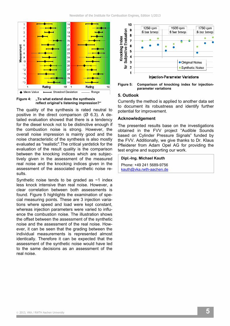
Synthetic noise tends to be graded as ~1 index less knock intensive than real noise. However, a clear correlation between both assessments is found. Figure 5 highlights the examination of spe-cial measuring points. These are 3 injection varia-tions where speed and load were kept constant, whereas injection parameters were varied to influ-ence the combustion noise. The illustration shows the offset between the assessment of the synthetic noise and the assessment of the real noise. How-ever, it can be seen that the grading between the individual measurements is represented almost identically. Therefore it can be expected that the assessment of the synthetic noise would have led to the same decisions as an assessment of the real noise.
Figure 5: Comparison of knocking index for injection-
parameter variations
5. Outlook
Currently the method is applied to another data set to document its robustness and identify further potential for improvement.
Acknowledgement
The presented results base on the investigations obtained in the FVV project “Audible Sounds based on Cylinder Pressure Signals” funded by the FVV. Additionally, we give thanks to Dr. Klaus Pfleiderer from Adam Opel AG for providing the test engine and supporting our work.
Dipl.-Ing. Michael Kauth
Phone: +49 241 5689-9756 [email protected]

Newsletter of the Institute for Combustion Engines, Edition 1/2013
6 2013, VKA / RWTH Aachen University
LPG System Comparison Despite the improvement of hybrid and battery electric vehicles the internal combustion engine remains the dominant source of propulsion in the upcoming decades and offers further development potential. Furthermore CO2-reduction potential can be exploited by the usage of alternative fuels. As a short and midterm action of the European fuel strategy the usage of gaseous fuels seems rea-sonable, particularly as the adaptation to existing engine concepts is less complex compared to oth-er alternative fuels. But for an increased usage of LPG fuels the European LPG fuel standard (EN 589) needs to be updated with regard to mod-ern engine technology with the aim to ensure LPG quality to be future capable and to achieve maxi-mum engine efficiency.
Within the FVV research project LPG System Comparison different LPG fuel formulations were investigated at the Institute for Combustion En-gines (VKA) with respect to their suitability for the application to modern gasoline TC-DI engines and their potential to increase engine efficiency for stoichiometric combustion systems. Therefore fundamental investigations were carried
out in order to work out the requirements regarding gas quality and different injection systems.
Fig. 1 summarizes the main fuel properties of the considered fuels. A conventional RON 95 E5 serves as reference fuel for all investigations. Among the LPG fuels LPG 1 (pure propane) re-veals the highest knock characteristic numbers (methane number and motor octane number). De-spite their different formulation LPG 4 and LPG 5 have the same motor octane number. LPG 2 holds a motor octane number at the lower end of DIN EN 589 and on the same level as the reference fuel RON 95 E5. Due to the lower density of all LPG fuel formulations the volumetric heating value is ~ 23 % lower than for conventional gasoline.
RO
N 9
5 E
5
LP
G 1
LP
G 2
LP
G 3
LP
G 4
LP
G 5
MON (DIN EN 589) 86.3 95.9 86.7 93.2 94.6 94.6
Methane number (MN) -- 32.3 18.4 21.4 17.6 28.5
Density (15 °C) / kg/m³ 749 508 566 548 553 526
Spec. enthalpy of vaporization for λ = 1 / kJ/kgair
29.5 27.1 25.1 24.6 23.9 25.6
Stoichiometric air requirement / 1 14.17 15.64 15.21 15.49 15.45 15.56
Lower heating value / MJ/l 31.45 23.19 25.59 25.04 25.04 23.95
Massfraction carbon / % 84.43 81.73 83.45 82.30 82.45 81.99
Massfraction hydrogen / % 13.22 18.28 16.56 17.70 17.59 18.01
Massfraction propane / % -- 99 29 39 26 70
Massfraction n-butane / % -- 0.16 30.58 41.33 25.68 20
Massfraction iso-butane / % -- 0.55 3.65 19.46 47.57 10.33
Figure 1: Fuel properties

Newsletter of the Institute for Combustion Engines, Edition 1/2013
2013, VKA / RWTH Aachen University 7
Three different LPG injections systems have been applied to a current state of the art turbocharged gasoline direct injection engine (Ford 1.6 l Eco-boost). For external mixture formation two availa-ble retro fit kits were used (gaseous port fuel injec-tion (PFI-gaseous) and liquid port fuel injection (PFI-liquid)). Furthermore a LPG direct injection (LPG-DI) via the conventional gasoline injection systems has been applied to the engine.
Fig. 2 shows the full load results for direct injec-tion, base compression ratio and engine at operat-ing temperature.
For all LPG fuels the same full load performance as for RON 95 E5 is achieved. Furthermore it can be stated that all LPG fuels significantly enhance the auto-ignition characteristics compared to the reference fuel. Advanced spark timing between 8 °CA and 17 °CA becomes possible, which leads to considerably advanced combustion phasing in terms of MFB50 % and positive effects on specific fuel consumption, combustion stability and en-richment demand for component protection. Even under full load operating conditions no considera-ble soot emissions are measureable for the LPG fuels and significant advantages arise compared to the reference fuel RON 95 E5. One explanation for
Figure 2: Results of engine speed variation at full load for direct injection and CR = 10
Engine speed variation; FL; Direct injection; CR = 10; Tcoolant = Toil = 90 °C
SOI, fuel pressure and valve timing according to production calibration
RON95 E5 LPG 1 (MN=32.3) LPG 2 (MN=18.4)
LPG 3 (MN=21.4) LPG 4 (MN=17.6) LPG 5 (MN=28.5)
100
150
200
250
300
Engine torque / Nm
0.0
0.2
0.4
0.6
0.8IMEP- standard deviation / bar
25
30
35
40
45Brake specific efficiency / %
-10
0
10
20
30Spark timing / ° CA BTDC
0
10
20
30
40MFB 50% / ° CA ATDC
0.8
0.9
1.0
1.1
1.2
Rel. air fuel ration / 1
0
4
8
12
16
Engine speed / (1/min)1000 2000 3000 4000 5000 6000
Brake specificHC-emissions / (g/kWh)
0.0
0.1
0.2
0.3
0.4
Engine speed / (1/min)1000 2000 3000 4000 5000 6000
Soot-emissions / FSN

Newsletter of the Institute for Combustion Engines, Edition 1/2013
8 2013, VKA / RWTH Aachen University
the soot-free combustion is the lacking amount of aromatic hydrocarbons in the LPG fuel formula-tions. There is no correlation for the fuel´s auto-ignition behavior and the motor octane number (fig. 3). Full load investigations reveal significant differences in terms of auto-ignition behavior for fuels with comparable motor octane (e.g. LPG 4 and LPG 5 or RON 95 E5 and LPG 2). A signifi-cantly more pronounced correlation is found for the methane number. The methane number is established to describe the anti-knock properties of gaseous fuels and mainly correlates with the propane content of the fuel.
As expected the efficiency differences under part load conditions are much lower between RON 95 E5 and LPG 5. All operating points of the load sweep are performed with stoichiometric mixture and in terms of MFB50 % only minor differences are present due to a slight knock restriction for RON 95 E5 at BMEP = 10 bar.
Despite the compression ratio increase by 3 units there is no knock restriction for LPG 5 for all con-sidered load points. Compared to the reference fuel the efficiency increase amounts to 1.6 % for BMEP = 3 bar and 3.6 % for BME = 10 bar.
For the full load investigations of the different LPG injection systems a further boundary condition has been defined. In consequence of the direct scav-enging of unburned fuel for low end torque opera-tion the maximum HC-emissions output is limited to the level for gasoline operation. The absolute limit is 1200 – 1400 ppm, which corresponds to brake specific HC-emissions of 8.5 g/kWh. Full
load calibration settings regarding injection timing, fuel pressure and valve timing correspond to the production calibration of the engine. The valve overlap for external mixture formation is reduced until the maximum HC emissions of 8.5 g/kWh appears. The injection timing was optimized for the vaporizer systems. Best results have been
0
5
10
15
20
25
Methane number (AVL) / 115 20 25 30 35
MFB 50% / ° CA ATDC
n = 1500 1/min n = 3000 1/min n = 5000 1/min n = 2000 1/min n = 4000 1/min n = 6000 1/min
thermodynamic optimum
0
5
10
15
20
25
Motor octane number (EN589) / 185 90 95 100 105
thermodynamic optimum
MFB 50% / ° CA ATDC
Figure 3: Full load correlation for the MFB50 % and the knock characteristic numbers
Figure 4: Results of a load sweep for direct injection at n = 2000 1/min for fuel individual adapted compression ratio
Load sweep; DI; 2000 1/min; Spindt = 1; Tcoolant = Toil = 90 °C
RON95 E5 (CR = 10) LPG 5 (CR = 13)
MON=86.3 MN=28.4
SOI, fuel pressure and valve timing according to production calibration
15
20
25
30
35
Mean effective pressure / bar0 2 4 6 8 10 12
Brake specificefficiency / %
6
8
10
12
14
Mean effective pressure / bar0 2 4 6 8 10 12
MFB 50% / ° CA ATDC

Newsletter of the Institute for Combustion Engines, Edition 1/2013
2013, VKA / RWTH Aachen University 9
achieved for an advanced injection strategy. Same strategy is also applied to liquid PFI injection sys-tem. For gaseous port fuel injection the pressure difference to the intake manifold amounts 2.5 bar. In case of the liquid port fuel injection the pressure varies in a range of 15 – 22 bar. For the LPG fuel formulations with high propane content the pres-sure is slightly increased in order to avoid gasifica-tion before the injection valves. The achieved en-gine torque at low engine speed (n = 1500 1/min) is reduced by 36 % in case of gaseous-PFI and by 27.5 % in case of liquid-PFI due to the reduced valve overlap.
As expected the various injection systems differ considerably in their auto-ignition behavior (fig. 5). Due to the significantly reduced engine torque for n = 1500 1/min for external mixture formation the most retarded MFB50 % in this operating point arises for direct injection. The most retarded spark timing for external mixture formation arises at n = 2000 1/min when the maximum engine torque of Md = 240 Nm is achieved. Gaseous-PFI is much
more prone to knock than both liquid injection sys-tems, which leads to the most retarded MFB50 %. However, also liquid-PFI tends to knock earlier than liquid direct injection. First from an engine speed n = 5500 1/min spark timing and MFB50 % converge again because of the higher enrichment demand for external mixture formation and there-fore less knock sensitivity and shorter combustion duration. In terms of combustion stability the direct injection concept reveals the best values, even slightly improved compared to gasoline direct in-jection. In the entire engine speed range the high-est efficiency is gained with direct injection.
Summarizing it can be stated, that the experi-mental investigations reveal the largest thermody-namic potential for the LPG direct injection system, which shows significant advantages over external mixture preparation systems. For the realization of this concept it is crucial to ensure liquid fuel supply under all operating conditions. The emission level of all three systems is significantly lower compared to conventional gasoline operation. Especially no
Figure 5: Results of the full load engine speed variation for different LPG injection systems and CR = 10
LPG 3; engine speed variation; FL; CR = 10; Tcoolant = Toil = 90 °C
Direct injection PFI-liquid PFI-gaseous
SOI, fuel pressure and valve timing according to production calibration
100
150
200
250
300Engine torque / Nm
no scavengingfor ext. mixtureformation possible
0.0
0.2
0.4
0.6
0.8IMEP - standard deviation / bar
-5
0
5
10
15
Spark timing/ ° CA BTDC
5
10
15
20
25MFB 50% / ° CA ATDC
25
30
35
40
45
Engine speed / (1/min)1000 2000 3000 4000 5000 6000
Brake specific efficiency / %
0.8
0.9
1.0
1.1
1.2
Engine speed / (1/min)1000 2000 3000 4000 5000 6000
Rel. air fuel ratio / 1

Newsletter of the Institute for Combustion Engines, Edition 1/2013
10 2013, VKA / RWTH Aachen University
considerable soot emissions could be detected. The comparison of different LPG fuels under direct injection shows, as expected, improved auto-ignition characteristics compared to gasoline oper-ation. LPG formulations with high propane content allow a compression ratio increase of 3 units for direct injection. A correlation between the motor octane number and auto-ignition tendency could not be determined. However, a much better corre-lation was found for methane number and auto-ignition tendency of the fuels.
“BREEZE!” on Hannover Messe 2013
Figure 1: BREEZE! on Hannover Messe 2013
BREEZE! is an abbreviation for “Fuel Cell Range Extender for Electric Vehicles: Zero Emissions!”. Marius Walters, engineer at the Institute for Com-bustion Engines (VKA) presented the project “BREEZE!” on the Hannover Messe 2013. Walters showed an electric Fiat 500 which will be equipped with a fuel cell developed in this project. For this range extender application a 30 kW PEM fuel cell stack with metallic bipolar plates and a very com-pact design is under development. The joint pro-ject of the Institute for Combustion Engines (VKA), FEV GmbH, Graebener Maschinentechnik and Duisburger Zentrum für Brennstoffzellentechnik (ZBT) is financially supported by the state North Rhine-Westphalia and the European Union. First praxis tests are planned for the year 2014.
Figure 2: BREEZE! Fuel Cell Range Extender Module
Dipl.-Ing. Marius Walters
Phone: +49 241 5689-9724 [email protected]
Dipl.-Ing. Marco Günther
Phone: +49 241 80-98363 [email protected]

Newsletter of the Institute for Combustion Engines, Edition 1/2013
2013, VKA / RWTH Aachen University 11
New Post Graduate Program Addressing E-Mobility The challenge to drastically reduce worldwide greenhouse gas emissions despite growing energy demand requires decisive changes in energy supply, conversion and storage technologies. For the transport sector, the electrification of the drivetrain combined with increasing electrical power generation from renewable sources is a promising approach to decrease the dependency on shortening crude oil and gas resources. However, the energy density of mobile electrical energy storage systems is still less than appropriate at present.
This demanding topic is addressed by a new post graduate program „Integrated Energy Supply Modules for Roadbound E-Mobility“ (mobilEM) at RWTH Aachen University. The program is funded by Deutsche Forschungsgemeinschaft (DFG) and explores the physical foundations of electro-chemical energy storage and its combination with novel fuel-operated range extender units. Fuel-operated range extenders allow a reasonable dimensioning of the electrical energy storage system size and its thermal conditioning. Additionally, an efficient air conditioning of the passenger compartment can be achieved.
Within a period of 4.5 years, the program gathers scientists from the areas of electrical energy storage, power electronics, combustion engines, electric motors, thermal management and control engineering, as shown in figure 1. One major focus is the interactions between the components inside the entire vehicle system.
The different research activities will be conducted under the supervision of professors Dirk Abel, Rik De Doncker, Lutz Eckstein, Kay Hameyer, Reinhold Kneer, Georg Jacobs, Stefan Pischinger, Heinz Pitsch, Dirk Uwe Sauer and Ulrich Simon as well as Dr. Julia Kowal. As part of the program, special-interest lecture series and custom qualification sessions are offered. This enables the participants to improve their knowledge in their individual research fields as well as to collect additional trans-disciplinary base knowledge in the neighboring research areas.
The recently established Center for Mobile Propulsion (CMP) offers ideal prerequisites to the participants of the program in order to perform their experimental as well as theoretical research work. It provides real-time interconnected laboratories for the investigation of batteries, electro-mechanical and chemical-mechanical energy converters, and complete hybrid power trains.
The program will start on October 1st, 2013. Applications can be addressed directly to the different participating institutes or professors. The vacant postgraduate positions at VKA can be found on our website www.vka.rwth-aachen.de.
Figure 1: Overview of topics covered in post graduate program mobilEM
Dipl.-Ing. Martin Jäger
Phone: +49 241 5689-9760 [email protected]

Newsletter of the Institute for Combustion Engines, Edition 1/2013
12 2013, VKA / RWTH Aachen University
E V E N T S 22nd Aachen Colloquium Automobile and Engine Technology October 7th – 9th 2013, Eurogress Aachen
The largest automobile and engine technology congress in Europe will take place on October 7th – 9th, 2013. The congress provides technical presentations addressing current challenges of the vehicle and powertrain industry. In the technical exhibition more than 60 exhibitors will present their products and services. In addition, program-related test vehicles, prototypes and aggregates will be shown on the ika test track. Registration for participants started in May and can be found on the website together with detailed information:
www.aachen-colloquium.com Aachen Acoustics Colloquium – AAC 2013 November, 25th – 27th 2013, Eurogress Aachen
Aachen is one of the most important centers for development and research in automotive acous-tics. This year, the colloquium takes place on No-vember 25th – 27th. In various technical presenta-tions the up-to-date and innovative methods and technologies in the fields of acoustics and vibra-tions of vehicles and drives are presented and discussed. The presentations are accompanied by a technical exhibition. Detailed information and registration for participants can be found here soon: www.aachen-acoustics-colloquium.com
IMPRINT Institute for Combustion Engines VKA – RWTH Aachen University Schinkelstraße 8 52062 Aachen Germany Phone: +49 241 80-95350 Editorial Team: Dr.-Ing. Martin Nijs [email protected] Dipl.-Ing. Marius Walters [email protected] aachen.de Sandra Wery, M.A. [email protected]