entitled by - utoledo.edu
84
A Thesis entitled Friction-Stir Riveting: an Innovative Process for Joining Difficult-to-Weld Materials by Samuel J. Durbin Submitted to the Graduate Faculty as partial fulfillment of the requirements for the Masters of Science Degree in Mechanical Engineering __________________________________________ Dr. Hongyan Zhang, Advisor, Committee Chair __________________________________________ Dr. Ahalapitiya Jayatissa, Co-advisor, Committee Member __________________________________________ Dr. Sarit Bhaduri, Committee Member __________________________________________ Dr. Patricia R. Komuniecki, Dean College of Graduate Studies The University of Toledo May 2012
Transcript of entitled by - utoledo.edu

A Thesis
entitled
Friction-Stir Riveting: an Innovative Process for Joining Difficult-to-Weld Materials
by
Samuel J. Durbin
Submitted to the Graduate Faculty as partial fulfillment of the requirements for the
Masters of Science Degree in Mechanical Engineering
__________________________________________
Dr. Hongyan Zhang, Advisor, Committee Chair
__________________________________________
Dr. Ahalapitiya Jayatissa, Co-advisor, Committee
Member
__________________________________________
Dr. Sarit Bhaduri, Committee Member
__________________________________________
Dr. Patricia R. Komuniecki, Dean
College of Graduate Studies
The University of Toledo
May 2012

ii
Copyright 2012, Samuel J. Durbin
This document is copyrighted material. Under copyright law, no parts of this document
may be reproduced without the expressed permission of the author.

iii
An Abstract of
Friction-Stir Riveting: an Innovative Process for Joining Difficult-to-Weld Materials
by
Samuel J. Durbin
Submitted to the Graduate Faculty as partial fulfillment of the
Requirements for the Masters of Science Degree in Mechanical Engineering
The University of Toledo
May 2011
Aluminum and magnesium alloys are expected to make considerable contributions in
reducing the weight of automobiles as they are increasingly used as an alternative to
steel; improving fuel economy and vehicle performance while simultaneously reducing
emissions. Before the wide-scale adoption of aluminum and magnesium alloys in the
construction of automobiles can take place, the difficulties of joining these materials must
be overcome. Two areas with promise include self-piercing riveting, in which a rivet is
driven into sheet metal, without predrilling a hole; and friction-stir welding, in which a
rotating tool is fed along the seam of the materials to be joined, mixing the materials
without melting them to form a joint. Both of these processes avoid melting the material
to be joined therefore not causing the undesirable changes in the metallurgical properties
associated with resistance spot welding.
Friction-stir riveting combines both friction-stir welding and self-piercing riveting.
The process involves driving a spinning rivet into sheet metal without predrilling a pilot
hole. A joint formed by this process has the benefits of a mechanical fastener similar to
self-piercing riveting, and of a material mixture zone similar to friction-stir welding;

iv
without suffering from the undesirable changes in mechanical properties associated with
more conventional welding techniques.
This work presents the basics of tooling design, a fundamental understanding of the
friction-stir riveting process, and the feasibility of joining difficult-to-weld materials
using this technique.

v
Acknowledgements
I would like to thank my advisor Dr. Hongyan Zhang and co-advisor Dr.
Ahalapitiya Jayatissa whose leadership and support over the past two years made this
research possible. I would also like to thank my co-researchers Genze Ma and Weiling
Wang for the great teamwork. I must also express my appreciation to Mr. John Jaegly,
Mr. Tim Grivanow and Mr. Randall Reihing of the University of Toledo MIME machine
shop, for their patience when asked to do the impossible, and the help they provided in
solving problems as they arose. Financial support provided by the National Science
Foundation and The University of Toledo was also greatly appreciated.

vi
Table of Contents
Acknowledgements.......................................................................................... v
Table of Contents ........................................................................................... vi
Objective ...................................................................................................... viii
List of Figures ................................................................................................ ix
1 Introduction ................................................................................................... 1
2 Friction-Stir Riveting Tool Design ............................................................... 8
2.1 Rivet Design.............................................................................................................. 8
2.2 Clamp design .......................................................................................................... 22
2.3 Driver design ........................................................................................................... 34
3 Friction-stir Riveting Process .....................................................................40
3.1 Material flow, and interface geometry at different depths of penetration .............. 41
4 Friction-Stir Riveting Process Characterization .........................................46
4.1 Effect of die on interface geometry ........................................................................ 46
4.2 Metallographic Analysis of the riveted joint microstructure .................................. 52
4.3 Joining of various materials .................................................................................... 55
4.4 Element mapping with electron scanning microscope............................................ 61
5 Conclusion ..................................................................................................65

vii
5.1 Summary ................................................................................................................. 65
5.2 Future work ............................................................................................................. 65
References ......................................................................................................69
List of Publications ........................................................................................71

viii
Objective
The goal of this thesis and of the associated research is to conduct a proof-of-concept
of the proposed friction-stir riveting process; to study the structure of these joints and
understand their influence on joint quality; and to conduct mechanical and metallurgical
testing to relate joint attributes to joint strength.

ix
List of Figures
1-1 A self-piercing riveted joint 3
1-2 Flawed self-piercing rivet joint 4
1-3. Friction-stir welding 5 1-4 Friction stir rivet 6
1-5 Cross section of friction stir riveted joint 7
2-1 Friction-stir riveted joint with critical dimensions labeled 8
2-2 Rivet geometry nomenclatures 9
2-3 First generation rivet design (1) 10
2-4 First generation rivet design (2) 10
2-5 Second generation design (1) 11
2-6 Second generation rivet design (2) 12
2-7 Simplest conceivable rivet design 13
2-8 Rivet design with 4-mm diameter bottom flange 14
2-9 Rivet design with 5-mm diameter bottom flange 15
2-10 Damaged rivet bottom flange 15
2-11 Rivet design similar to Figure 2.9 except with reinforced bottom flange 16
2-12 Rivet design with 6-mm bottom flange 17

x
2-13 Specimen with fractured rivet 18
2-14 Similar to Figure 2.12, but with a sharper tip 19
2-15 Rivet design similar to Figure 2.14 but with 4-mm rivet stem 20
2-16 Final rivet design used in research 21
2-17 Rivet ready for insertion, with insufficient clamping 23
2-18 Cross section of riveted joint with severe sheet separation 24
2-19 Second generation clamp technique 25
2-20 Riveted joint sample with minor sheet separation 25
2-21 Third generation clamping technique (overall view) 27
2-22 Third generation clamp with stress concentrating washer 27
2-23 Third generation clamp; top view 28
2-24 Third generation clamp; bottom view 28
2-25 Third generation clamp; side view; washer visible at center on bottom 28
2-26 Riveted joint, with slight sheet separtion to right of rivet 30
2-27 Riveted specimen, without sheet seperation 30
2-28 Fourth generation clamp technique 32
2-29 Fourth generation clamp top view 32
2-30 Fourth generation clamp in use 33
2-31 Fourth generation clamp bottom view, with welded washer 33
2-32 Fourth generation clamp side view 34
2-33 Driver with matching rivet 36

xi
2-34 Phillips driver 36
2-35 Rivet with desired Phillips driver slot 37
2-36 Final rivet design with diver slot 37
3-1a Inserted 2.5 mm 42
3-1b Inserted 2.7 mm 42
3-1c Inserted 2.8 mm 42
3-1d Inserted 3.0 mm 42
3-1e Inserted 3.3 mm 43
3-1f Inserted 3.6 mm 43
3-2 Orientation of bisecting a riveted joint 45
3-3 Cross sectional view of riveted joint cut without offset sectioning 45
4-1 Typical friction stir riveted joint 47
4-2 Joint samples without die 49
4-3 Joint samples with small die 49
4-4 Joint samples with large die 49
4-5 Small and large dies 50
4-6 Riveting procedure setup with a die 51
4-7 Over etched specimen of an Al joint 52
4-8 Under etched sample 53
4-9 Various etchings 54-55
4-10 Typical riveted aluminum joint 55

xii
4-11 Microscopic view of aluminum joint 56
4-12 Two sheets of magnesium alloy riveted togeather 57
4-13 Microscopic view of magnesium sample 57
4-14 Composit joint macro view 58
4-15 Composite joint micro view 59
4-16 Composite joint, macro view 60
4-17 Composite joint, microscopic view 60
4-18 Section of rivet to undergo element mapping 61
4-19 Image from electron scanning microscope 62
4-20 Iron 63
4-21 Carbon 63
4-22 Manganese 63
4-23 Chromium 63
4-24 Nickel 64
4-25 Silicon 64
4-26 Magnesium 64
4-27 Zinc 64
4-28 Oxygen 64
4-29 Aluminum 64
4-30 Potential rivet for further research 66
4-31 Rivet sample with partial void visible 67

xiii
4-32 Potential location of rolling bearings 68

1
1 Introduction
Resistance spot welding has proven to be a versatile method for the joining of steels,
being used extensively in the automotive industry and other industries. As the automotive
industry progresses to using more aluminum alloys and magnesium alloys in order to
reduce vehicle weight to improve performance and economy, while also reducing
emissions, alternative joining methods will be required. Resistance spot welding of
aluminum alloys and magnesium alloys are possible, but create complications making it
impractical for the large scale automated use required by the automotive industry. For
example the lower electrical resistance of both aluminum and magnesium alloys requires
higher electric current during resistance spot welding in order to generate the necessary
heat, which in turn leads to shorter electrode life. Two alternative joining methods that
show promise for the joining of materials that are difficult for resistance spot welding are
self-piercing riveting, and friction stir welding.
Self-piercing riveting is an attractive alternative to resistance spot welding for
difficult-to-weld metals, or dissimilar metals. The repeatability of self-piercing riveting
along with the low cost of joint formation makes it ideal for the automotive industry [1].
The process of self-piercing riveting involves applying a compressive load onto the two
sheets of material that are to be riveted together, then driving a semi-tubular rivet through
the upper layer and into the bottom layer. A die cavity is placed underneath the material

2
to be riveted, as the rivet is being driven into the material, the material fills the cavity,
and the shape of the cavity forces the rivet to flare outward, causing the layers of material
to be anchored together by the rivet as seen in Figure 1-1. Figure 1-1 illustrates the cross
section of a self-piercing rivet joint, the steel rivet appears black, the upper layer is a 2
mm thick sheet of aluminum, and the bottom layer is a 1.4 mm thick layer of steel. The
steel appears black in the photo as a result of polishing, since steel polishes to a finer
finish than aluminum. When light is reflected off the polished aluminum it is scattered,
making it convenient to photograph; when light is reflected off the polished steel it does
not scatter as much as with aluminum. Instead of scattering, the reflected light as is the
case with aluminum, the steel experiences specular reflection, where light coming from a
single direction will reflect off a mirror-like surface with a single outgoing direction. Due
to the specular reflection, the steel appears black, as no light from the steel reaches the
camera. One can see how the rivet completely passes through the upper layer of
aluminum and enters the lower layer of steel, without penetrating through the lower layer
of steel. The ‘w’ shape of this specimen is a result of the die that is placed underneath the
sheet metal during the riveting process. The shape of the die causes the rivet to flare out
during riveting helping to form a strong joint.

3
Figure 1-1. A self-piercing riveted joint
Self-piercing riveting has the advantage of being able to conveniently join dissimilar
metals as in Figure 1-1. A self-piercing riveted joint can be made inexpensively and in
large quantities with high level of consistency making it ideally suited for the automotive
industry. There are limitations to self-piercing riveting, for example when riveting sheets
of magnesium alloys, the brittleness of magnesium alloys (with comparison to aluminum
alloys) can cause fractures to occur where the stress is concentrated as the rivet is being
driven into the sheets of magnesium alloys as seen in figure 1-2. Figure 1-2 reveals where
a fracture has occurred during the riveting process.
2mm

4
Figure 1-2. Flawed self-piercing rivet joint [2]
Friction stir welding is another area of interest for the joining of difficult to weld
materials. To form a square butt joint using friction stir welding, a cylindrical tool is fed,
rotating, along the interface between the two pieces of material to be joined. The rotating
tool uses friction to heat the material to be welded together to the point of becoming
plastic without heating the material all the way to its melting point. As the tool is fed
along the interface, the material in front of the tool is softened from the heat, and then is
pushed around and behind the tool, filling the void that would have been created as the
tool passes. Figure 1-3 depicts a rotating tool advancing up the joint line of the two pieces
to be joined. The tool has a probe that penetrates the material, as well as a shoulder to
apply a downward force on the material; the friction of the rotating shoulder heats the
material before the material comes into contact with the probe.

5
Figure 1-3. Friction stir welding [3]
Friction stir welding has the advantage of being a solid state joining process,
meaning that the material is never heated to the liquid state, as in more tradition welding
techniques, such as arc welding. Since the material is not heated to such extremes, the
material does not go through undesirable metallurgical changes, associated with more
conventional welding techniques, negating the need for heat treatment after the welding
is complete.
Friction stir riveting is a cross between self-piercing riveting and friction stir
welding. A rivet, as shown in Figure 1-4, is spun and driven into multiple layers of sheet
metal. As in friction stir welding, the heat generated by friction softens the metal to a
plastic state, without completely melting it, allowing it to deform without fracturing.
Similar to self piercing riveting, no predrilled pilot hole is necessary, reducing the time
and cost per joint, and a mechanical fastener is left in place to provide strength. Figure 1-
4 shows three different views of the identical friction-stir rivet: on the left is a top view
revealing a plus sign that allows the driver to spin the rivets as it is pushing the rivet into
sheet metal; the middle rivet reveals the profile of the rivet; the rivet on the right is a
bottom view of the rivet. As the rivet is being driven into the sheet metal, the softened
material fills the empty space surrounding the rivet stem, as seen in Figure 1-5.

6
Figure 1-4. Friction stir rivet
Figure 1-5 presents the cross section of a friction stir riveted joint, again the rivet
(which is made of steel) appears black due to the specular reflection. The joint in Figure
1-5 joins sheets of aluminum that are both 2 mm thick. To the left of the rivet one can
see the interface between the two layers of aluminum. A die was used below the two
layers of aluminum during the riveting process to allow some of the material replaced by
the rivet to flow downward, causing the bump at the center on the bottom of this
specimen. This thesis describes the experiences and results as the feasibility of friction
stir riveting was explored.
1.5mm

7
Figure 1-5. Cross section of friction stir riveted joint
2mm

8
2 Friction-Stir Riveting Tool Design
2.1 Rivet Design
To produce the most robust friction stir riveted joints possible, rivets were designed
to produce the largest stirred and mixed zone (W in Figure 2-1) possible, and a large
interlock (L). These characteristics, mixed zone, and mechanical interlocking, along with
solid bonding provide the riveted joint with its strength. For this research attention was
restricted to studding the effects of the mixed zone and interlocking area.
Figure 2-1. Friction-stir riveted joint with critical dimensions labeled
The nomenclature used to describe the different parts of the rivet can be seen in
Figure 2-2. The bottom portion of the rivet will be called rivet bottom flange; the central
portion of the rivet, the rivet trunk; and the top portion of the rivet, the rivet head.
W L
2mm

9
Figure 2-2 Rivet geometry nomenclatures
The two original friction stir rivet designs, Figures 2-3 and 2-4, featured a concave
rivet head. The logic behind this design is that as the rivet was penetrating the softened
sheet metal, the concave shape of the rivet head would help to redirect the displaced
material back towards the central rivet stem, filling in any potential void. This design
turned out to be impractical, machining this rivet on a lathe, be it a CNC or manual is all
but impossible. In order to machine the concave shape of the rivet head, the cutting tool
would be required to be approximately 1 mm in diameter, which would lead to
unreasonable short cutting tool life. After consulting multiple machine shops it was
decided to abandon this design, and come up with a new simpler rivet design.
Rivet Head
Rivet Trunk
Rivet Bottom Flange
2mm

10
7.0mm
4.4mm
3.0mm
Figure 2-3. First generation rivet design (1)
7.0mm
6.0mm
3.0mm
Figure 2-4. First generation rivet design (2)
Two second generation rivet designs seen in Figures 2-5 and 2-6, appeared to be
more manufacturable; it was decided to proceed with the design in Figure 2-5. This
design also proved to be unsuccessful, due to the small 2.5-mm diameter of the rivet

11
stem. As the rivet was being spun and driven into the sheet metal the rivet head would
break off at the stem, due to the torque being applied from the spinning motion. It was
concluded that a rivet stem diameter of 2.5 mm was insufficient.
7.0mm
6.0mm
3.0mm
2.5mm
Figure 2-5. Second generation design (1)

12
7.0mm
4.0mm
3.0mm
2.5mm
Figure 2-6. Second generation rivet design (2)
After months without progress, it was decided to take a step back, and focus the rivet
design with manufacturability, and ease of insertion in mind. The rivet design in Figure
2-7 does not have a bottom flange as in all previous and subsequent rivet designs. The
lack of bottom flange offers the advantage of ease of insertion during the riveting
process, and the disadvantage of producing a weak joint. This rivet design was more
about having a foundation upon which to build, as opposed to forming very strong joints.
Using this rivet design the first successful joints were formed, while the complications
with driving the rivet, and in clamping down the sheet metal could be focused on.

13
Figure 2-7. Simplest conceivable rivet design
After the success experienced with the rivet in Figure 2-7, a rivet that would produce
a stronger joint was desired. Figure 2-8 presents the next rivet design, this one similar to
the design in Figure 2-7 except the new design features a 4 mm diameter lower flange, to
increase the degree of interlocking and therefore, the strength of the joint.

14
Figure 2-8. Rivet design with 4-mm diameter bottom flange
Knowing that the riveted joint strength would improve from having a larger bottom
flange, the design in Figure 2-9 was conceived. This design was similar to the designs in
Figures 2-7 and 2-8 except for having a 5-mm diameter bottom flange. When this rivet
design was successfully inserted into the sheet metal, it was assumed that the best friction
stir riveting joint had just been constructed. Upon closer examination the cross section
revealed that the bottom flange curled up during insertion, from the load applied upon the
bottom flange by the sheet metal as it was being driven into the sheet metal, as seen in
Figure 2-10. In addition, there are unfilled voids near the rivet trunk as seen in the figure.

15
Figure 2-9. Rivet design with 5-mm diameter bottom flange
Figure 2-10. Damaged rivet bottom flange
To combat the problem seen with the design in Figure 2-10 without reducing the
diameter of the bottom flange, it was decided to increase the thickness of the bottom
4mm

16
flange, to give the flange the strength that was required to withstand the stresses
encountered during the riveting process. This new design is illustrated in Figure 2-11.
This design worked with a high level reliability, and produced strong and consistent
joints.
Figure 2-11 Rivet design similar to Figure 2-9 except with reinforced bottom flange
The rivet in Figure 2-11 performed well, but it was assumed that if a rivet with a 6-
mm bottom flange could be successfully inserted into the sheet metal, the joint would be
of a higher quality. So the rivet design in Figure 2-12 was produced. This design
produced mixed results; sometimes the rivet would survive insertion successfully, but
other times the rivet would fracture at the rivet stem during insertion, as can be seen in

17
Figure 2-13. A variety of spindle speeds and feed rates were attempted to find a more
reliable process, but without success.
Figure 2-12. Rivet design with 6-mm bottom flange

18
Figure 2-13. Specimen with fractured rivet
Disappointed by the failure of design 2-12, but not wanting to compromise with the
6-mm bottom flange, another rivet with a 6-mm bottom flange was designed, as seen in
Figure 2-14. This design featured a sharper tip, to concentrate the heating affect from
friction, and reduce loading applied during insertion. This design proved to be no more
reliable than the design in Figure 2-12; the rivet would still occasionally fracture at the
stem during insertion.

19
6.0mm
3.0mm
7.0mm
4.5mm
Figure 2-14 Similar to Figure 2-12, but with a sharper tip
Unable to improve upon the consistency of the rivet design of Figure 2-12 or 2-14,
heat treatment after machining was conducted. It was also decided to strengthen the weak
point of the rivet, by increasing the diameter of the rivet stem from 3 to 4 mm as seen in
Figure 2-15. The rivet design in Figure 2-15 is primarily the same as in Figure 2-14
except with an increased diameter rivet stem to 4 mm. This rivet design performed well,
producing a sound joint, and being able to handle the stresses applied during the riveting
process.

20
6.0mm
4.0mm
7.0mm
4.5mm
Figure 2-15. Rivet design similar to Figure 2-14 but with 4-mm rivet stem
While the performance of the rivet design in Figure 2.15 was of the highest quality,
the design evolved into Figure 2-16 with a stem that converges starting at the rivet head
with a wider diameter, then slims to a narrower diameter at the bottom flange. This new
design also features a slimmed down rivet head, and is overall shortened by 0.5mm. The
tip of the rivet is less pointed than the design in Figure 2-15; there were no observed
variations in performance relating to the minor changes that were made upon the angle of
the tip of the rivet.

21
7.0mm
3.75mm
4.25mm
6.0mm
4.0mm
Figure 2-16. Final rivet design used in research
The rivet design in Figure 2-16 performed flawlessly, always producing a solid joint
without suffering damage caused during the riveting process, as seen with some of the
earlier rivet designs. Additional research might continue to explore rivet design. Perhaps
a bottom flange with a larger diameter than 6 mm, or a rivet head diameter larger than 7
mm would improve performance.
As mentioned previously, all rivets were heat treated in order to avoid the problems
seen in figure 2-13, where rivets broke at the stem due to the torsional stress. The process
used for heat treatment is as follows.
1. Preheat- Heat the rivets to 1200˚ F for 30 minutes.
2. Hardening- Heat the samples to 1500 ˚F for an additional 60 minutes.
3. Quench- Quench in oil at room temperatures, then clean oil off samples.
4. Temper- Heat rivets to 400-500 ˚F and hold for 2 hours.

22
2.2 Clamp design
When the first successful riveted joints started being produced, it was assumed that
the downward force being applied to the rivet by the driver, and hence the downward
force being applied to the two layers of sheet metal by the rivet, would be sufficient to
hold the sheet metal down, during the riveting process. The sheet metal was then clamped
in a manner to prevent horizontal travel as seen in Figure 2-17. Figure 2-17 shows a rivet
in the center of the frame, with the driver holding the rivet ready for insertion; in the
foreground the front jaw of the vice is visible (out of focus), and the background shows
the rear jaw of the vice. This clamping technique immediately proved insufficient. Figure
2-18 shows the cross section of an early specimen made under such a clamping
technique.

23
Figure 2.17. Rivet ready for insertion, with insufficient clamping
This clamping technique immediately proved insufficient as can be seen in Figure 2-
18. Figure 2-18 displays the cross section of an early specimen taken using the setup seen
in Figure 2-17. As can be seen in Figure 2-18 the top layer of aluminum is separated from
the bottom layer as the material displaced by the rivet, flows in-between the two layers of
sheet metal.

24
Figure 2-18. Cross section of riveted joint with severe sheet separation
It was soon realized that a downward force would need to be applied during the
riveting process. A clamp was applied as seen in Figure 2-19, applying a strong
downward force to the upper layer of aluminum, to prevent the separation seen in Figure
2-18. This technique was a vast improvement over the previous technique, but still
allowed for some minor separation as seen in Figure 2-20. Figure 2-20 shows a riveted
joint taken using the clamping technique shown in Figure 2-19; it should be noted that a
large ‘C’ shaped piece with tails is visible to the left of the rivet in this sample; this ‘C’ is
merely a plastic clamp used as an aid for metallographic specimen preparation and has
nothing to do with the quality of the riveted joint. The separation seen between the two
layers of aluminum was deemed unacceptable, even though it represented a vast
improvement from the sample presented in Figure 2-18.
2mm

25
Figure 2-19. Second generation clamp technique
Figure 2-20. Riveted joint sample with minor sheet separation
2mm

26
Figure 2-21 shows the third generation of clamping technique which employed a steel
plate clamped tightly to the sheets to apply a downward force evenly to the sheet metal.
The goal of this technique was to apply a compressive load to the sheet metal
immediately surrounding the rivet to prevent the separation seen in Figure 2-20. When
applying a compressive load to the steel plate, the plate would bow under the loading and
the resulting loading would be applied to the sheet metal away from the rivet due to the
concave down shape of the steel plate under loading. The resulting samples using this
technique were of no better quality than those seen in Figure 2-20.
To correct this problem a steel washer was welded to the bottom of the plate. The
steel plate and washer were then cut open from the side so they could be easily placed
around the rivet and driver while the rivet and driver were in place, for convenience. This
clamping setup is as portrayed in Figure 2-21. Figures 2-22 through 2-25 show the
clamping mechanism in greater detail, and Figures 2-24 and 2-25 show the washer that
was welded to the bottom of the clamp. The washer was welded to the clamp to
concentrate the loading applied to the sheet metal, around the rivet, to further reduce the
chances of separation during the riveting process.

27
Figure 2-21. Third generation clamping technique (overall view)
Figure 2-22. Third generation clamp with stress concentrating washer

28
Figure 2-23 Third generation clamp; top view
Figure 2-24 Third generation clamp; bottom view
Figure 2-25 Third generation clamp; side view; washer visible at center on bottom

29
This technique worked well and was used for the majority of the specimens made in
this research; there were however weaknesses to this system. When applying a load to the
clamp it would often deform under loading, and after repeated cycles of use, the clamp
would experience permanent deformation, requiring straightening.
A second problem observed with this clamping technique is that since approximately
25 percent of the washer was cut out for ease of use, the clamp only applied a load, on the
sheet metal, to a certain percent of the perimeter of the sheet metal surrounding the rivet
as the rivet was being driven into the sheet metal; allowing minor separation to occur on a
small portion of a riveted joint.
When taking cross sections of riveted joints, occasionally the sample would be cut
through the area with minor sheet separation, as seen in Figure 2-26 (to the right of the
rivet), and sometimes the sample would not be cut through the areas with minor
separation, as seen in Figure 2-27; creating inconsistent appearances of joints while
samples were made under identical process conditions. (Note that these two specimens
were created using different dies).

30
Figure 2-26. Riveted joint, with slight sheet separtion to right of rivet
Figure 2-27 Riveted specimen, without sheet seperation
To overcome the problems associated with the third generation of clamping
technique, a new clamp was devised as seen in figures 2-28 through 2-32. Figure 2-28
2mm
2mm

31
shows the clamp with the sheet metal underneath the clamp, not visible. The large hole in
the center of the clamp goes approximately 50% through the clamp. At the bottom center
of the large hole, there is a small hole that proceeds all the way through the clamp, as
seen in Figure 2-29, just large enough for the rivet and driver tip to fit through, for the
rivet to reach the sheet metal. Figure 2-30 shows the rivet and driver down, just to the
point of making contact with the sheet metal to be riveted. Figure 2-31 is a photo of the
bottom view of the clamp; this clamp features a washer welded to the bottom of it,
similar to that used in the third generation, while in Figure 2-32 the profile of the clamp is
visible. Using this clamp solves the problems associated with the third generation
clamping technique, in that a load was applied to the sheet metal in a complete 360
degrees surrounding the rivet, and that it would be impossible to deform this clamp under
reasonable conditions. This clamp produced no observed flaws or drawbacks. On a side
note it is much larger than is necessary; it was made from a piece of scrap metal found in
the UT machine shop, and, in order to save time, was not machined to a smaller size.

32
Figure 2-28 Fourth generation clamp technique
Figure 2-29 Fourth generation clamp top view

33
Figure 2-30 Fourth generation clamp in use
Figure 2-31 Fourth generation clamp bottom view, with welded washer

34
Figure 2-32 Fourth generation clamp side view
2.3 Driver design
Anxious for progress when the research first started, it was decided that attention
should be focused on overall rivet design, consequently little thought was given to the
details of how exactly the rivet would be spun and driven into the sheet metal that had no
pilot hole. Once rivets were in hand, the first attempt planned to drive them into sheet
metal was very simple. The driver used was nothing more than a cylinder, with the flat
head of the cylinder mating to the flat head of the rivet. The driver was then spun and
applied a downward force to the rivet, counting on nothing more than the frictional force
between the rivet and cylindrical driver to transmit the torque and overcome the friction
of the rivet against the sheet metal. This attempt did not so much as scratch the sheet
metal that it was hoped it would penetrate.
The next attempt involved scoring the head of the cylinder to increase the friction
between the rivet and the driver; this ended with identical results to the previous attempt.
The next attempt was to use the same cylindrical driver, this time with adhesive backed
sandpaper stuck to the cylinder head, again to increase friction between the rivet and

35
cylinder driver. Again the friction between the rivet and the sheet metal proved greater
than the friction between the rivet and sandpaper covered cylinder driver head. Once the
rivet stopped rotating with the driver head, the adhesive on the sandpaper failed, and the
sandpaper came off the driver tip. Thinking that perhaps if the adhesive had not failed on
the sandpaper, this design might have worked, it was decided to simply glue sand directly
onto the face of the driver. It was hoped that the sand would provide the grip on the rivet
head to keep it spinning during the riveting process, and that the glue would keep the
sand securely attached to driver face, unlike the adhesive backed sandpaper. The glue
holding the sand to the driver failed, and this attempt was no more successful than all the
previous attempts. At this point it was decided to give up on the simple solution that had
been attempted.
The machinists at the University of Toledo were witness to the repeated failures;
anxious to help, one of the machinists designed and fabricated a driver as seen in Figure
2-33. On the right of figure 2-33 is the driver, and a rivet to match the driver is on the
left. This design appeared to be the solution to the driver problem; unfortunately the
driver was crushed during the first use under the torsional and compressive loading.
Although this driver design did not work, it did act as a guide to point future driver
designs in the right direction.
A Phillips style driver as seen in Figure 2-34 seemed a reasonable solution to the
driver problem. However, machining a rivet with a Phillips driver slot as seen in Figure
2-35 turned out to be unreasonably complicated and time consuming. A more
machineable design was made as seen in Figure 2-36.

36
Figure 2-33 Driver with matching rivet
Figure 2-34 Phillips driver

37
Figure 2-35 Rivet with desired Philips driver slot
Figure 2-36 Final rivet design with diver slot
A machinist could with ease modify the rivet design in Figure 2-16 to a usable rivet
as seen in Figure 2-36. A Phillips screw driver was then purchased, handle cut off, and
the very tip of driver cut off, to provide a flat surface to mate with the slots on the rivet;

38
the inside corners of driver filed down, to ensure the driver would fit inside of the rivet
driver slots. The first Phillips driver purchased was a number 3 driver, and little thought
was given to this choice. After the driver had been assembled as previously mentioned,
the first successful joints were formed. However, the success rate was not 100 percent:
occasionally the rivet would start to wobble as it was spinning, and then be shot out from
under the driver; other times the rivet would again stop spinning as was the problem
before the new driver was used. The driver would continue to spin with a heavy
compressive load applied to the rivet, stripping the rivet head, and damaging the driver.
Damage to the driver was sometimes fixable with a file, and other times needed to be
replaced. After going through a few screw drivers in this manner it was concluded that a
reasonable driver had not yet been found. Shopping for another screwdriver after yet
another driver had been damaged beyond the point of repair; it was decided to buy a
number four Phillips screw driver instead of the number threes that had been purchased
up until that point. The diameter of the number 4 is larger than the number 3; this
increase in diameter of the number 4 Phillips driver prevented the occasional problems
experienced with the number 3 Phillips driver. This was accomplished by the fact that the
number four driver was approximately the same diameter as the rivet, while the number
three driver was of a smaller diameter than the rivet. When the driver had a smaller
diameter than the rivet, the driver focused the downward loading towards the center of
the rivet, as opposed to applying the load evenly throughout the head of the rivet all the
way towards the perimeter. This centralized loading on the rivet provided less control of
the rivet, and was responsible for the occasion problem of rivet wobble and ejection. The
centralized loading was also responsible for the other problems with this design: as the

39
rivet is being spun and driven into the sheet metal a large amount of torque is required to
overcome the frictional force of the rivet against the sheet metal, occasionally this friction
was too high for the rivet. When the friction became high enough, the rivet would stop
spinning while the driver continued spinning; this would instantly strip out the driver
slots on the rivet head (destroying the rivet) and damaging the driver. When using the
new driver constructed from a number four Phillips, this was no longer an issue, the
larger diameter of the driver distributed the torsional stress evenly all the way to the
perimeter of the rivet during insertion, providing the strength to overcome the frictional
forces. This driver provided the reliability that was required for this research.

40
3 Friction-stir Riveting Process
A CNC milling machine was used for the riveting process. The die would be
clamped in the table clamp, and the two layers of sheet metal to be riveted together would
be placed on to the top of the die. The clamp to be used (as described in Section 2-2)
would be placed on the sheet metal in alignment with the driver, so that the clamp would
not interfere with the driver as it spun and drove the rivet into the sheet metal, and
clamped down with adequate tightness to prevent the sheet metal separation seen in
Section 2-2. A rivet would be placed on the tip of the driver and held in place with a
magnet. The table of the mill would be raised manually until the rivet came into contact
with the sheet metal; in an ideal situation if the rivets were all exactly the same length,
the table would be raised to a set height, as opposed to raising the table until the rivet
came into contact with the sheet metal. Once the sheet metal was raised to come into
contact with the rivet, the magnet used to temporarily hold the rivet to the driver would
be removed. The CNC milling machine was preprogrammed to spin a rivet at a
predetermined spindle speed, drive the rivet into the sheet metal at a specified feed rate,
to a certain depth. The spindle speed used for this research varied from 1000 to 3000
R.P.M.’s, and the typical feed rates that were used ranged between 0.05 and 0.20 inch per
minute. Once the program was started on the mill, the feeding was usually paused to
allow the spindle to spin the rivet, with a slight downward load applied to the sheet metal,

41
for 60 seconds, to generate heat from friction to preheat the sample before the rivet was
driven into the sheet metal; although the necessity of this 60 second preheat is
questionable, more samples would need to be taken to prove if preheating has any effect.
After the 60-second warm up, the CNC mill would drive the spinning rivet into the sheet
metal as specified. At the end of the cycle the clamp was manually removed from the top
of the sheet metal, and the joint was then ready for analysis.
3.1 Material flow, and interface geometry at different depths of penetration
Figures 3-1a-f show a cross sectional view of progressive steps of a rivet
penetrating sheets of aluminum at increasing depths. It should be noted that the geometry
of the rivet in Figure 3.1a appears unique compared to the rest of the rivets in Figure 3-1.
The rivet in Figure 3-1a has a flat horizontal top, which is different from the others in
Figure 3-1. Actually all the rivets in Figure 3-1 are identical; the difference in appearance
is the result of the different rotational angles of the rivet with respect to the section line
using an abrasive disc cutter to cut the specimen in half, in order to view the cross
section. Figure 3-2 depicts the possibilities of cutting two identical rivets in half by an
abrasive disc cutter (the thick black line represents the disc cutter). When cutting a
specimen as in Figure 3-2a a cross section similar to that in Figure 3-1a would be
produced, and when cutting a sample across the slots on the rivet head as in Figure 3-2b
the resulting cross section of the rivet would resemble those in Figures 3-1b-f. One
should be aware that care must be taken when cutting small samples like these for
metallographic examination. One must not cut the sample directly along the center, but
leave an approximately 1-2 mm offset, as seen in Figure 3-2. One must take into account
the material lost during the disc cutting, approximately 1mm, and the material lost during

42
grinding and polishing phase, again around 1mm, or else the finished cross section
sample will not be at the center of the rivet, but off to one side as shown in Figure 3-3.
All photos in Figure 3-1 were taken with an identical die, identical rivet penetrating the
identical two sheets of 2 mm thick aluminum alloy. Figures 3-1a and b are slightly
different from other photos in that they have a layer of cement above the top layer of
aluminum. The cement was used merely to hold the rivet in place during cutting,
grinding, and polishing as in these two cases the rivet/sheets were not bonded together.
The cement is unnecessary for other specimens due to sufficient rivet penetration.
Fig 3-1a Inserted 2.5 mm Fig 3-1b Inserted 2.7 mm
Fig 3-1c Inserted 2.8 mm Fig 3-1d Inserted 3.0 mm
3mm 3mm
3mm 3mm

43
Fig 3-1e Inserted 3.3 mm Fig 3-1f Inserted 3.6 mm
Figure 3-1a shows a rivet penetrating to a depth of 2.5 mm. Only one layer of
aluminum is present in this photo because the lower layer of aluminum did not bond with
the upper layer. The aluminum is allowed to deform under the loading applied from the
rivet to take the shape of the die; this is the reason why a rivet penetrating 2.5 mm did not
pierce a sheet of aluminum 2 mm thick.
An interesting observation from this photo is that the softened aluminum starts to
flow back towards the rivet stem after the rivet bottom flange passes through the material.
Figure 3-1b depicts a rivet penetrating to a depth of 2.7 mm. In this sample the upper
layer of aluminum does bond with the lower layer, but if one looks closely at this sample
one can see the horizontal interface between the upper sheet and the lower sheet; as the
interface approaches the rivet from the left and the right, the interface curls downward
managing to stay below the rivet. The rivet does not fully pierce the upper layer of
aluminum, but it does form a weak bond between the two sheets of aluminum merely
from the heat generated and the compressive loading applied during the riveting process.
The softened aluminum flowed back towards the rivet stem a little more successfully than
in Figure 3-1a, it appears that the stirred aluminum started to make contact with the back
surface of the rivet head, which should help to direct the aluminum back towards the rivet
3mm 3mm

44
stem. Continued riveting made the lower surface of the lower sheet of aluminum under
loading to take the shape of the die. It did not, however, fully take the shape of the die at
this stage of riveting. The sample in Figure 3-1c was taken at a depth of 2.8 mm. The
softened aluminum almost completely filled the void surrounding the rivet stem; a close
comparison with the previous sample in Figure 3-1b shows little change in geometry. The
bottom surface of the lower layer of aluminum at this stage does deform to the shape of
the die more noticeably than that in Figure 3-1b.
When the penetration was increased to a depth of 3.0 mm as in Figure 3-1d, the
softened aluminum filled the entire void surrounding the rivet stem. The interface
between the two sheets of aluminum again curled down to stay below the rivet at this
time, but with a closer inspection towards the bottom tip of the rivet it can be found that
the rivet did fully pierce the upper layer of aluminum. In this specimen the void next to
the rivet trunk was fully filled and the die cavity was filled more than in the previous
stage, but still not completely. When penetrating to a depth of 3.3 mm as in Figure 3-1e,
the void surrounding the rivet stem was kept completely filled, and the die appeared
completely filled. The rivet appeared to completely puncture the top sheet of aluminum
throughout the entire width of the rivet bottom flange. The sheet interface still curled
downward. Figure 3-1f shows a rivet penetrating to a depth of 3.6 mm. At this stage the
void surrounding the rivet stem was again entirely filled, the die was completely filled,
and the rivet completely punctured the top sheet of aluminum and penetrated into the
bottom sheet. Upon close examination of the interface geometry, it can be seen that the
interface is now approximately horizontal, with a slight upward curve, which is
preferable, instead of curling down.

45
Figure 3-2 Orientation of bisecting a riveted joint
Figure 3-3 shows the results of cutting a riveted specimen in half along the center
line without offset as shown in Figure 3-2; and then grinding the sample too aggressively.
Figure 3-3. Cross sectional view of riveted joint cut without offset sectioning
2mm

46
4 Friction-Stir Riveting Process
Characterization
4.1 Effect of die on interface geometry
The use of a die underneath the sheet metal during the riveting process proved essential
for maintaining reasonable joint interface geometry, and hence a quality joint. The goal
of using a die being to insert the rivet to the proper depth, while maintaining the ability to
control the shape and orientation of the interface. Figure 4-1 shows a good friction stir
riveted joint; the rivet is inserted into the sheet metal to the proper depth, the interface,
visible on the left, is mostly horizontal and points towards the vertical center of the rivet,
neither curling up towards the rivet head or curling down towards the rivet bottom flange.
The die used to make the joint in Figure 4-1 is responsible for the concave up shape of
the sheet metal, visible towards the bottom center of the specimen. The extra material that
fills the die also serves as a barrier to guard against corrosion, and provide a joint with an
air tight seal.

47
Figure 4-1 Typical friction stir riveted joint
Figures 4-2a and b are cross sectional views of a joint with a rivet penetrating to a
depth of 3.8 mm without the use of a die during the riveting process. Figure 4-2a was
taken with a standard camera and lens using an extension tube to bring a subject closer to
the camera than is normally possible, and hence photographing the subject in higher
detail (the majority of the macro photos in this work were taken in such a manner). The
photograph in Figure 4-2b (of the same specimen) was taken after etching, and this time
through a microscope, with an 80x magnification, instead of a standard camera lens.
Photographing through a microscope offers a few advantages and one disadvantage. The
main advantage is having greater magnification capability than using a standard lens with
an extension tube. Secondly using a microscope to take photos can be more forgiving
when focusing, versus a standard lens with an extension tube (which has a very shallow
depth of field). Lastly the light source from a microscope passes through the lens striking
the sample perpendicularly and reflecting straight back into the lens and out the eyepiece;
the light striking the sample nearly perpendicularly provides greater detail and a new
perspective when compared to light reflecting off the sample at a steep angle as is
2mm

48
required when photographing a sample using an extension tube due to the closeness of
the sample to the lens, often times only 1-2 cm.
The disadvantage of using a microscope is the stricter limitation to wide angle
viewing than that provided by a conventional camera lens (one cannot see the entire
specimen at once). To overcome this problem Figure 4-2 b is actually a collage of 6
photos stitched together; this stitching technique is responsible for the inconsistency in
exposure seen in Figures 4-2b, 4-3b and 4-4b. From Figures 4-2a and b the lack of die is
evident when viewing the bottom surface of the lower sheet of aluminum which is
completely horizontal and lacks a downward bulge seen in Figures 4-3 and 4-4. All of the
material displaced by the rivet during penetration is forced up and most is ejected as
metal ‘chips’ during the riveting process; this is partially evident when looking to the left
and right of the rivet head in Figure 4-2a. In Figure 4-2b the geometry of the interface
becomes apparent, and the interface can be seen to curl upwards steeply towards the rivet
head. This is not desirable, as the interface comes close to contacting the rivet head.
Figure 4-3a and b are a specimen with a penetration depth of 3.8 mm but this time using a
small die with a volume 7.33 mm3; photographed with different techniques. The effect of
die can be seen in the downward bulge of the bottom of the lower sheet. Figures 4-4a
and b are on a sample with the same penetration depth of 3.8 mm, but using a larger die
with a volume of 21.2 mm3. Again the effect of the die is apparent by the downward
bulge on the bottom of the lower sheet of aluminum underneath the rivet. Close attention
should be given to the interface geometry in Figures 4-2b, 4-3b and 4-4b; as all samples
were prepared under identical conditions to identical depths; and the only difference is
the use of a die underneath the sample during riveting. In Figure 4-2b (without a die) the

49
interface curls upward too steeply as previously discussed; in Figure 4-3b (with a small
die) again the interface curls upward, but of a lesser degree. In Figure 4-4b the interface
is nearly horizontal, or perhaps curling slightly downwards. It should be mentioned that
the sample in Figure 4-4 is not an ideal joint due to the inadequate rivet penetration
depth, as this specimen was taken merely as a comparison to the ones shown in Figures
4-2 and 4-3, not to represent a quality riveted joint.
Figure 4-2a. No die, unetched Figure 4-2b. No die, etched
Figure 4-3a. Small die, unetched Figure 4-3b. Small die, etched
Figure 4-4a. Large die, unetched Figure 4-4b. Large die, etched
2mm
2mm
2mm 4mm
4mm
4mm

50
Figure 4-5 is the drawings of two different dies used for the vast majority of the samples
taken during this research, both dies have spherical cavity caps. The ‘large’ die has a
cavity volume of 21.2 mm3, and that for the ‘small’ die is 7.33 mm
3.
7.89mm
0.85mm
0.50mm
6.90mm
V = 21.2 mm^3
V = 7.33 mm^3
Figure 4-5 Small and large dies
Figure 4-6 depicts the riveting procedural setup with the die (labeled in figure)
placed underneath the sheets of aluminum. Not visible in this photo, but located directly
underneath the rivet on the die is the hemispherical cap hollow that forms the downward
bulge seen in figures 4-4a and b.

51
Figure 4-6. Riveting procedure setup with a die
Finite element analysis reveals that a joint with a horizontal interface is the most
desirable in terms of joint strength, that is with the interface neither curling up, nor down.
In reality producing a completely horizontal interface proved to be nearly impossible.
The volume of the die should be equal to the volume of the rivet penetrating below the
original interface of the sheet metal, and then the rivet should penetrate to the material to
the exact depth, to displace the desired volume, to produce the desired horizontal
interface. This proved to be difficult, while using a CNC mill to drive the rivet to the
exact depth was not a problem, minor inconsistencies of just a few thousands of an inch
in the length of the rivet made rivet insertion to the exact depth difficult. It should also be
noted that while the F.E.A results suggest that a completely horizontal interface is the
Die

52
best, experimental results reveal that a rivet penetrating slightly too deep, producing an
upward curving interface, is very little different from that of a completely horizontal
interface.
4.2 Metallographic Analysis of the riveted joint microstructure
In order to gain further insight into the microstructure of the base material and any
potential metallurgical changes brought on from the riveting process, specimens were
etched to aid in microscopic analysis.
Figure 4-7 Over etched specimen of an Al joint
1mm

53
Figure 4-8. Under etched sample
Various etching procedures were tested to reveal the microstructures of the friction-stir
riveted joints. After many trials an optimal procedure was developed. The etching
involves submerging the sample in an acid bath that is 25 percent nitric acid and 75
percent phosphoric acid, and the mixture is heated to 60 degrees C. The duration of time
for the submerging in the acid bath is a function of the concentration of acids, for this
research 30 seconds of etching was found proper. Figure 4-7 (the same sample as in
Figure 4-2, etched for 2 minutes as in Figure 4-2d) shows a sample that was likely over
etched; while Figure 4-8 is of a sample etched for 15 seconds that would have benefited
from a longer etching. Figure 4-9 shows 4 different views of the same sample taken with
progressively longer etching viewed through a microscope with an 80X magnification. In
these photos the rivet is on the side of the image, with the rivet head in the upper right,
1mm

54
the rivet trunk in the central right, and the rivet bottom flange in the lower right corner of
the images. On the left side a line is visible, entering from out of the frame, which is the
interface between the upper and lower layers of aluminum. The samples in Figure 4-9
reveal the effect of progressively etching time on the aluminum and steel of the samples.
The steel of the rivet in Figure 4-9a starts off polished similar to a mirror, then oxidizes
almost instantly when etched, after 2 minutes in the acid bath the steel rivet is covered
with a thick layer of multi-colored rust. The goal of the etching is to observe the
aluminum though and not the steel rivet so little attention was paid to the steel. Etching
for around 30 seconds appeared to work best for the samples taken during this research.
Figure 4-9a. Unetched Figure 4-9b. Etched 30 seconds
1mm 1mm

55
Figure 4-9c. Etched 1minute Figure 4-9d. Etched 2 minutes
4.3 Joining of various materials
All previous samples seen in this thesis join two sheets of 2-mm aluminum alloy
5754 as seen in Figures 4-10 and 4-11. Figure 4-11 is a microscopic view of the same
sample as seen in Figure 4-10. In addition to the joints made on aluminum alloy 5754,
magnesium alloy AZ31 was also used in this research for the feasibility of friction-stir
riveting of Mg alloys and dissimilar metals.
Figure 4-10. Typical riveted aluminum joint
1mm 1mm
2mm

56
Figure 4-11. Microscopic view of aluminum joint
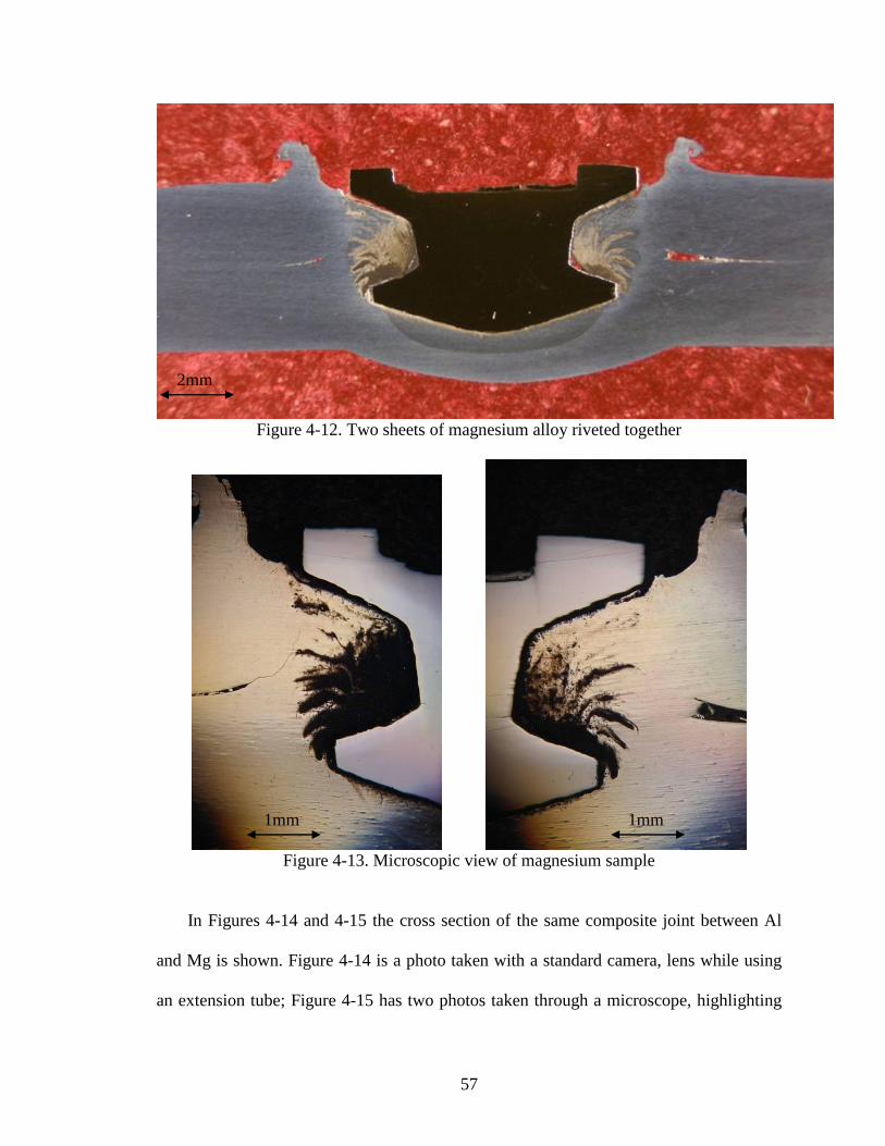
Figures 4-12 and 4-13 are of a sample riveting two sheets of 2-mm sheets of
magnesium alloy AZ31. The magnesium can be seen to be discolored above the rivet
bottom flange and surrounding the rivet stem. This discoloration appeared to form during
the grinding and especially the polishing phase of sample preparation, possibly a reaction
with the poishing compounds used. When the sample was originally cut with a disc
grinder it was not discolored, and as soon as the polishing of the sample was complete
and the sample was washed and dried the evolution of the discoloration would stop.
These samples were taken in the exactly same manner as the aluminum samples and they
were also prepared in the same manner.
1mm
1mm
57
Figure 4-12. Two sheets of magnesium alloy riveted together
Figure 4-13. Microscopic view of magnesium sample
In Figures 4-14 and 4-15 the cross section of the same composite joint between Al
and Mg is shown. Figure 4-14 is a photo taken with a standard camera, lens while using
an extension tube; Figure 4-15 has two photos taken through a microscope, highlighting
2mm
1mm 1mm

58
the area of interest. In this sample magnesium alloy AZ31 was used as the top layer,
while aluminum alloy 5754 was used on the bottom.
Figure 4-14. Composit joint macro view
2mm

59
Figure 4-15. Composite joint micro view
The joint featured in Figures 4-16 and 4-17 is also a composite joint, with a layer of
aluminum alloy 5754 on top riveted to a layer of magnesium alloy AZ31 on the bottom.
There are three layers of separate materials present in this sample, all clearly
distiguishable from each other. The steel rivet appears black in Figure 4.16, the upper
layer of aluminum appears dark bluish grey, and the lower layer of magnesium as a
lighter gray. An interesting observation is that a ‘cap’ of aluminum stuck to the bottom
rivet flange during insertion is unlike what was seen in Figures 4-16 and 4-17 when the
magnesium was on top and the aluminum on the bottom. It should also be noted that
there does not appear to be any meaningful mixing of the two separate sheets being
riveted together in this sample or the previous sample in Figures 4-16 and 4-17, as was
1mm 1mm

60
seen earlier when two sheets of aluminum or two sheets of magnesium were riveted
together, as seen in Figures 4-3 and 4-4.
Figure 4-16. Composite joint, macro view
Figure 4-17. Composite joint, microscopic view
2mm
2mm

61
4.4 Element mapping with electron scanning microscope
Figure 4-18. Section of rivet to undergo element mapping
Area of element mapping
.75mm

62
The boxed-in area in Figure 4-18 shows the section of a sample to undergo element
mapping using an electron scanning microscope. This sample was made using two sheets
of magnesium alloy AZ31. Figure 4-19 displays the image from the scanning electron
microscope, with the rivet taking up the left half the photograph.
Figure 4-19. Image from scanning electron microscope
As can be seen in Figures 4-20 through 4-25 the composition of the O1 tool steel is
mainly iron (Figure 4-20), with traces of carbon (Figure 4-21), manganese (Figure 4-22),
chromium (Figure 4-23), nickel (Figure 4-24), and silicon (Figure 4-25). While the
.5mm

63
composition of AZ31 magnesium alloy is mainly magnesium (Figure 4-26), with traces
of zinc (4-27), manganese, silicon, and aluminum (Figure 4-29). The polishing compound
used to prepare this sample aluminum oxide, efforts were made to thoroughly wash
samples after polishing, but figures 4-28 and 4-29 suggest that more of an effort to clean
this sample after polishing would have been worthwhile.
Figure 4-20. Iron Figure 4-21. Carbon
Figure 4-22 Manganese Figure 4-23. Chromium

64
Figure 4-24. Nickel Figure 4-25. Silicon
Figure 4-26. Magnesium Figure 4-27. Zinc
Figure 4-28. Oxygen Figure 4-29. Aluminum

65
5 Conclusion
5.1 Summary
Friction-Stir riveting forms a joint that is comparable in strength to resistance spot
welding, or self-piercing rivets. This technique can be applied to joining sheets of
magnesium alloy AZ31 together without the drawbacks associated with resistance spot
welding or self-pierce riveting. The strength of a friction-stir riveted joint is heavily
dependent upon the depth of insertion of the rivet, and is also to a lesser extent dependent
upon the rotational speed during insertion and the rate of insertion. Further research is
required to prove the importance of these factors in joint strength.
5.2 Future work
Rivet design evolved drastically over the course of this research, and the results of
the final design were suitable. Further studies in this area would be beneficial; figure 4-30
shows a rivet design with a 9mm rivet head diameter, compared to the 7mm rivet head
diameter used for this research. Many of the failures during tensile test of the previous
rivet design occurred when the rivet lodged with the lower layer, and the rivet head
pulled through the upper layer. This enlarged rivet head should reduce that mode of
failure. A wider rivet bottom flange was the perpetual goal of rivet design, a 7mm wide
bottom flange may prove to be impractical to insert into sheet metal, or it may penetrate
with no more difficulty than the 6mm bottom flange, and produce a superior joint.

66
9.0mm
6.0mm
4.0mm
4-30. Potential rivet for further research
Due to the expense and time required to manufacture rivets by hand, not as many rivets
were produced as could be desired. For further research it would be desired to have a
rivet design more suitable for larger scale production, in order to conduct more extensive
testing on the effects of process parameters such as spindle speed, and feed rate.
Occasionally during rivet insertion, the rivet and driver would develop a wobble,
instead of the rivet penetrating straight down into the sheet metal the rivet would ‘walk’
in a circular motion during insertion. The effects of this can be seen in figure 4-31, to the
right of the rivet in this figure is a partial void left behind from the rivet wobbling to the
left and to the right during insertion.

67
Figure 4-31. Rivet sample with partial void visible.
The severity of this ‘walk’ could be reduced by using a shorter driver that was
thicker in diameter, in order to reduce driver deformation. A different solution to
completely do away with insertion wobble would be to insert a roller bearing into the
clamp itself. A roller bearing could be inserted into the circled area of the clamp as seen
in figure 4-32; with a bearing in place the driver would be capable of traveling up and
down, but would be prevented from moving in a circulation motion as was sometimes
observed.
2mm

68
Figure 4-32. Potential location of rolling bearings

69
References
[1] Y. Xu, Characterization of self-piercing riveted joints. Ph.D. Dissertations, The
University of Toledo March 2006
[2] Y. Durandet, R. Deam, A. Beer, W. Song, S. Blacket, Laser assisted self-pierce
riveting of AZ31 magnesium alloy strips. Materials and Design. 31 (2010) S13-
S16.
[3] Osaka East Urban Area, Industry-Government-Academia Collaboration Project on
FSW 2004 export-japan, Inc. http://www.mosaka.com/fsw/en/fsw/about_fsw.html
[4] Hongyan Zhang and Jacek Senkara, Resistance Welding: Fundamentals and
Applications. CRC Press/Taylor & Francis Group, 2nd
edition, Boca Raton,
London, New York. ISBN 978-1-4398537-1-9 (hardback), 978-1-4398537-2-6
(electronic). 2011. 656 pages, 360 illustrations.
[5] S. Durbin, G. Ma W. Wang, A. Jayatissa, and H. Zhang, Friction-stir riveting-a
new jointing method for Difficulty-to Weld Metals, submitted to Welding Journal,
Nov. 2011.
[6] Z. Li, C. Hao, J. Zhang, and H. Zhang, 2007: Effects of sheet surface conditions
on electrode life in aluminum welding, Welding Journal, vol. 86 (4), pp. 34 to 39-
s.
[7] B. Wang, C. Hao, J. Zhang and H. Zhang, 2006: A New Self Piercing Riveting
Process and Strength Evaluation. Transactions of the ASME, J. Manuf. Sci. Eng,
vol. 128 pp. 580-587.
[8] H. Zhang, J. Senkara, B. Wang, and Z.Gan, 2010: Self-piercing Riveting Al
Alloys, 6th
International Conference on Advances in Production
Engineering(APE’10), 17-19 June 2010,Warsaw, Poland.
[9] H. Luo, New joining techniques for magnesium alloy sheets, MS Thesis, Institute
of Metal Research, Chinese Academy of Sciences, May 2008.

70
[10] H. Luo, C. Hao, J. Zhang, Z. Gan, and H. Zhang, 2010: Characteristics of
Resistance Welding Magnesium Alloys AZ31 and AZ91, submitted to Welding
Journal, May 2010.
[11] W. Lee, Y. Yeon, S. Jung. Joint properties of friction stir welded AZ31B-H24
magnesium alloy. Materials Science and Technology, 2003, 19(6):785-790.
[12] S. Lathabai, M Painter, G. Cantin, and V. Tyagi. Friction spot joining of an
extruded Al-Mg-Si alloy, Scripta Materialia, 2006, 55:899-902.
[13] H. Seung, C. Park, Y. Sato, H. Kokawa. Effect of microtexture on fracture
location in friction stir weld of Mg ally AZ61 during tensile test. Scripta
Materialia, 2003, 49(2): 161-166.
[14] Y. Sato, H. Seung, C. Park, M. Michiuchi, and Hiroyuki Kokawa. Constitutional
liquation during dissimilar friction stir welding of Al and Mg alloys. Scripta
Materialia, 2004, 50:1233-1236.
[15] J. Esparza, W. Davis, L. Murr. Microstructure-proerty studies in friction-stir
welded thixomolded magnesium alloy AM60. Material Science, 2003, 38(5):941-
952.
[16] A. Somasekharan, L. Murr. Microstructures in friction-stir welded dissimilar
magnesium alloys and magnesium alloys to 6061-T6 aluminum alloy, Materials
Characterization, 2004, 52(1):49-64.
[17] H. Zhang and J. Senkara, Resistance Welding: Fundamentals and Applications.
CRC Press/Taylor & Francis Group, Boca Raton, London, New York. ISBN 0-
8493-2346-0. 2006. 431 pages, 300 illustrations.

71
List of Publications
1. H. Zhang, A. H. Jayatissa, S. Durbin, and G. Ma: What if They Are Not Weld-able?
Management and Production Engineering Review" (MPER), a quarterly journal
published by the Polish Academy of Sciences, submitted Oct. 2011.
2. S. Durbin, G. Ma, A. Jayatissa, and H. Zhang, 2011: Characterization of Friction Stir
Riveting Process, submitted to Welding Journal, Nov. 2011.
3. G. Ma, S. Durbin, W. Wang, A. Jayatissa, and H. Zhang, 2012: Performance of Friction
Stir Riveted Joints, to be submitted to Welding Science and Technology.
4. G. Ma, S. Durbin, W. Wang, A. Jayatissa, and H. Zhang, 2012: Characteristics of
Friction-Stir Riveted Joints, 15th Sheet Metal Welding Conference, Oct., 2012, Livonia,
MI.
5. S. Durbin, G. Ma, A. Jayatissa, H. Zhang, and J. Bohr, 2012: Friction-Stir Riveting, 15th
Sheet Metal Welding Conference, Oct., 2012, Livonia, MI.
6. Poster: Feasibility Study of Hybrid Friction-Stir Riveting, A.H. Jayatissa, G. Ma, S.
Durbin, and H. Zhang, 2011 National Science Foundation (NSF) Civil, Mechanical and
Manufacturing Innovation (CMMI) Conference, held January 4-7, 2011 in Atlanta,
Georgia.