ENTC463Worm and Worm Gear
26
Worm and Worm Gear ENTC 463 Mechanical Design Applications II
-
Upload
ram-shewale -
Category
Documents
-
view
263 -
download
0
Transcript of ENTC463Worm and Worm Gear
Worm and Worm Gear
ENTC 463Mechanical Design Applications II
ENTC 463
• Lab. #2 Gears• To be scheduled• Thompson 009B
ENTC 463
• HW#7 Worm and Wormgear• Due 2/28/2008• Chapter 8 – 55• Chapter 10 – 19
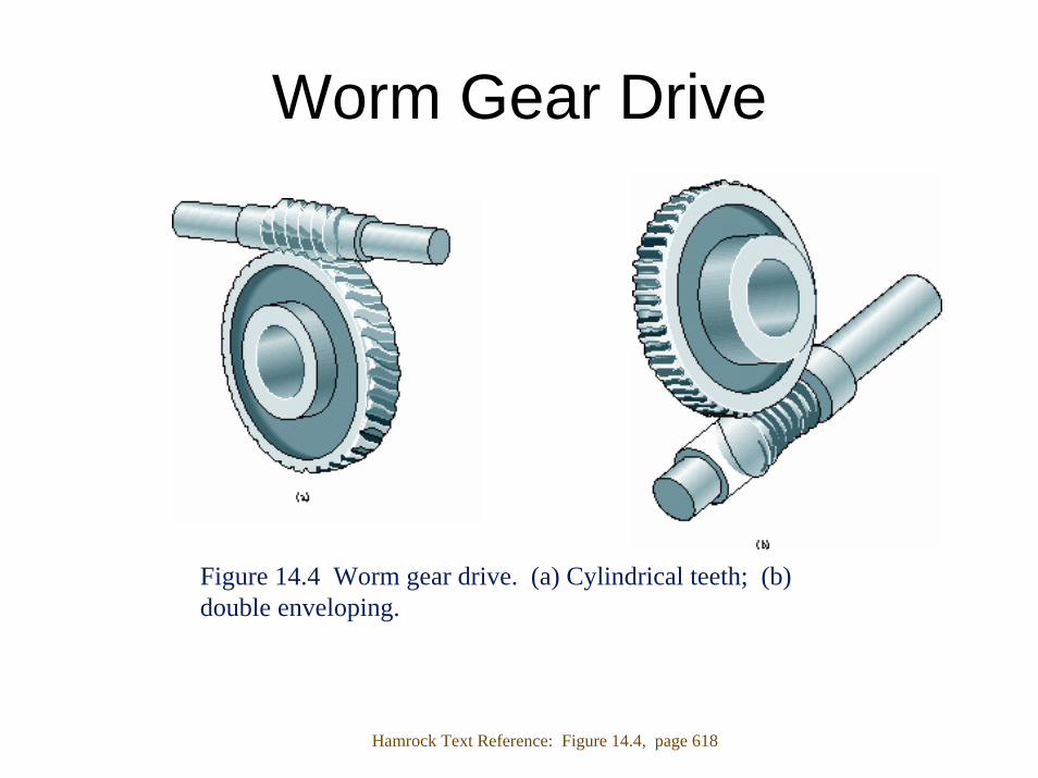
Worm Gear Drive
Figure 14.4 Worm gear drive. (a) Cylindrical teeth; (b) double enveloping.
Hamrock Text Reference: Figure 14.4, page 618
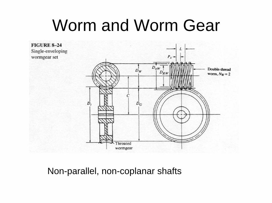
Worm and Worm Gear
Non-parallel, non-coplanar shafts
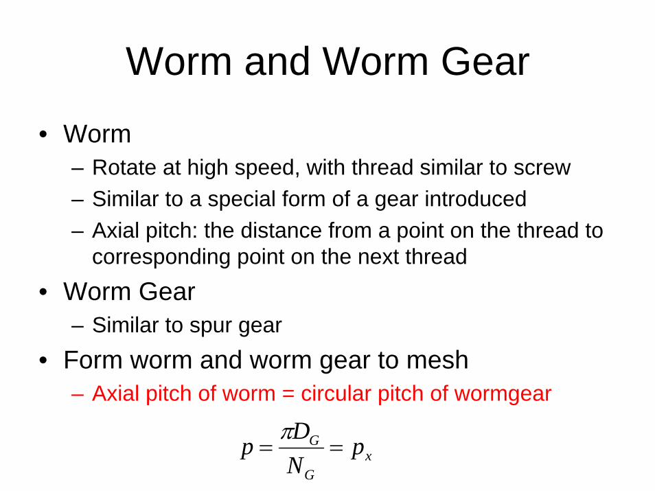
Worm and Worm Gear
• Worm– Rotate at high speed, with thread similar to screw– Similar to a special form of a gear introduced– Axial pitch: the distance from a point on the thread to
corresponding point on the next thread• Worm Gear
– Similar to spur gear• Form worm and worm gear to mesh
– Axial pitch of worm = circular pitch of wormgear
xG
G pNDp ==π
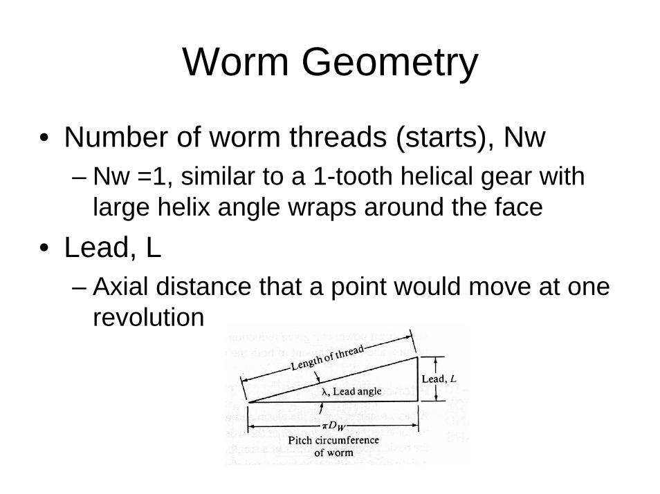
Worm Geometry
• Number of worm threads (starts), Nw– Nw =1, similar to a 1-tooth helical gear with
large helix angle wraps around the face• Lead, L
– Axial distance that a point would move at one revolution
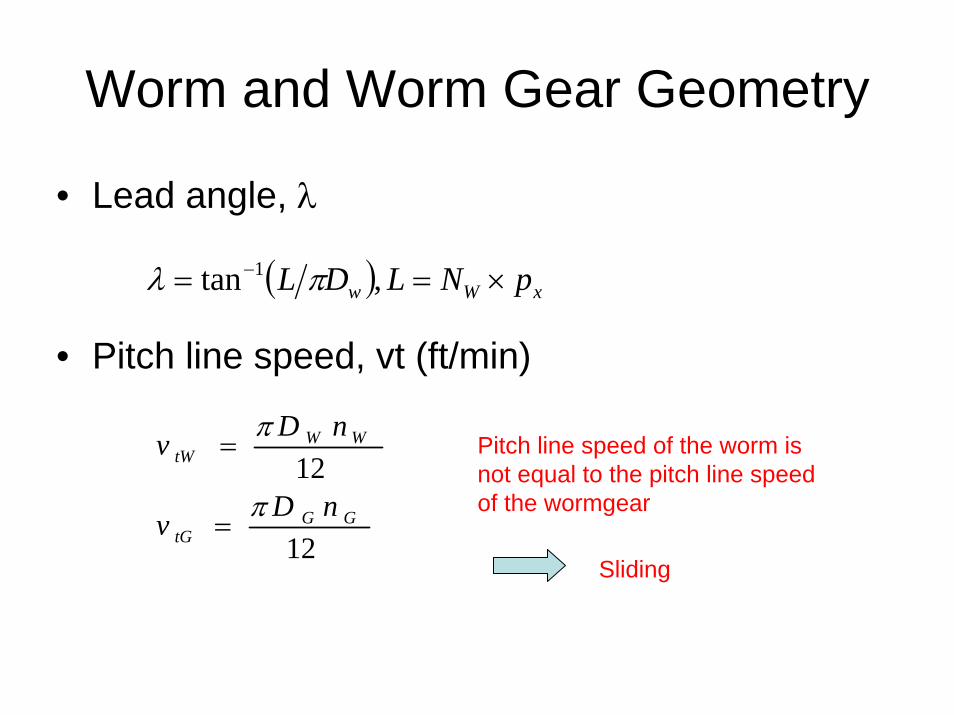
Worm and Worm Gear Geometry
• Lead angle, λ
• Pitch line speed, vt (ft/min)
( ) xWw pNLDL ×== − ,tan 1 πλ
12
12GG
tG
WWtW
nDv
nDv
π
π
=
= Pitch line speed of the worm is not equal to the pitch line speed of the wormgear
Sliding
Next Thursday2/28/2008
Meet @ Thompson 009B
ENTC 463Mechanical Design Applications II
Higginbotham to Winniford– 2:20 to 3:00 PMAllen to Hagan – 3:00 to 3:35 PM
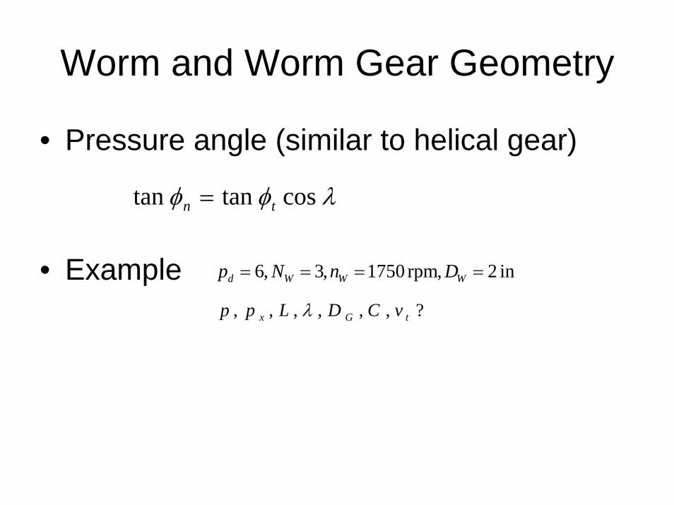
Worm and Worm Gear Geometry
• Pressure angle (similar to helical gear)
• Example
λφφ costantan tn =
in 2,rpm 1750,3,6 ==== WWWd DnNp
?,,,,,, tGx vCDLpp λ
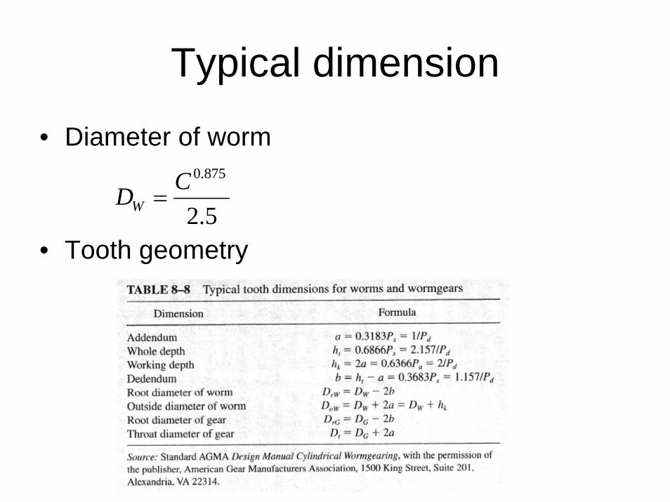
Typical dimension
• Diameter of worm
• Tooth geometry5.2
875.0CDW =
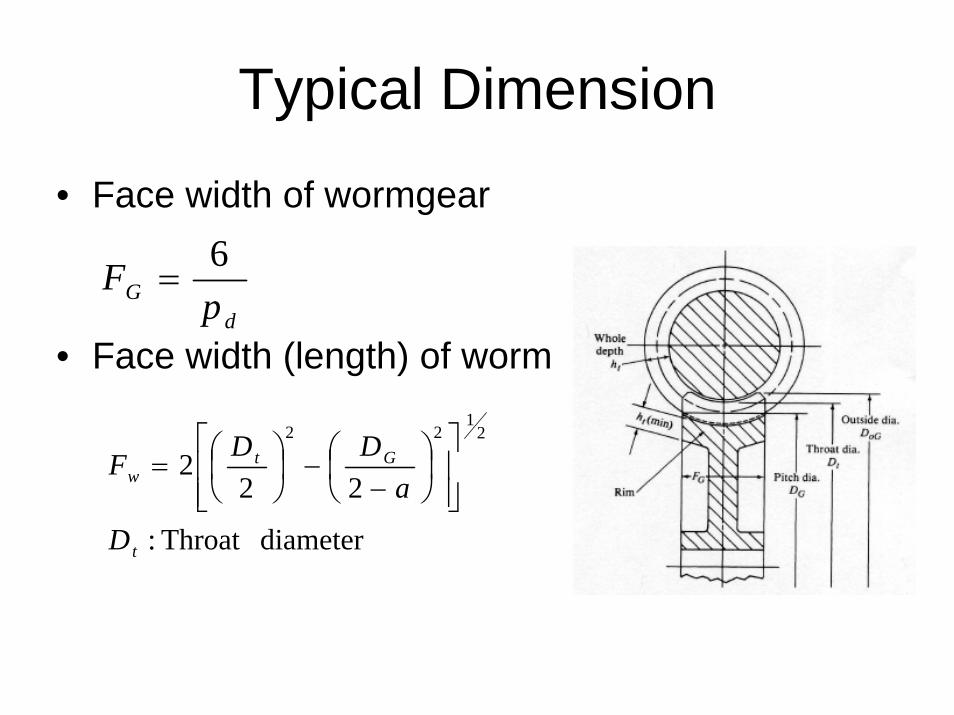
Typical Dimension
• Face width of wormgear
• Face width (length) of wormd
G pF 6
=
diameterThroat :
222
21
22
t
Gtw
D
aDDF
⎥⎥⎦
⎤
⎢⎢⎣
⎡⎟⎠⎞
⎜⎝⎛
−−⎟
⎠⎞
⎜⎝⎛=
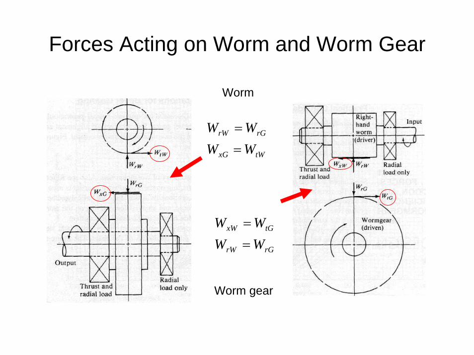
Forces Acting on Worm and Worm Gear
Worm
Worm gear
tWxG
rGrW
WWWW
==
rGrW
tGxW
WWWW
==
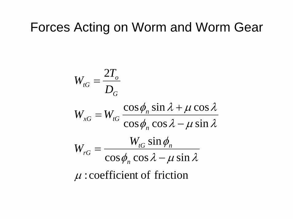
Forces Acting on Worm and Worm Gear
friction oft coefficien :sincoscos
sinsincoscoscossincos
2
μλμλφ
φλμλφλμλφ
−=
−+
=
=
n
ntGrG
n
ntGxG
G
otG
WW
WW
DTW
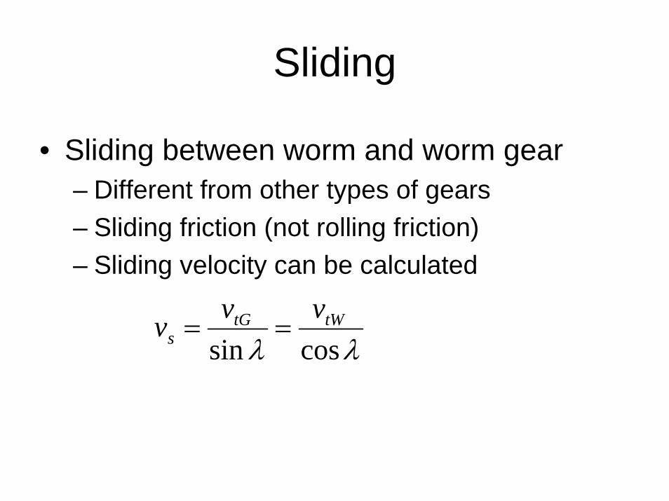
Sliding
• Sliding between worm and worm gear – Different from other types of gears– Sliding friction (not rolling friction)– Sliding velocity can be calculated
λλ cossintWtG
svvv ==
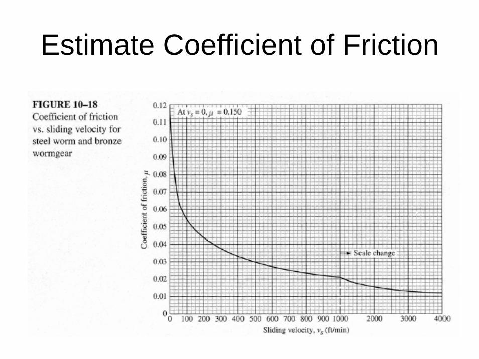
Estimate Coefficient of Friction
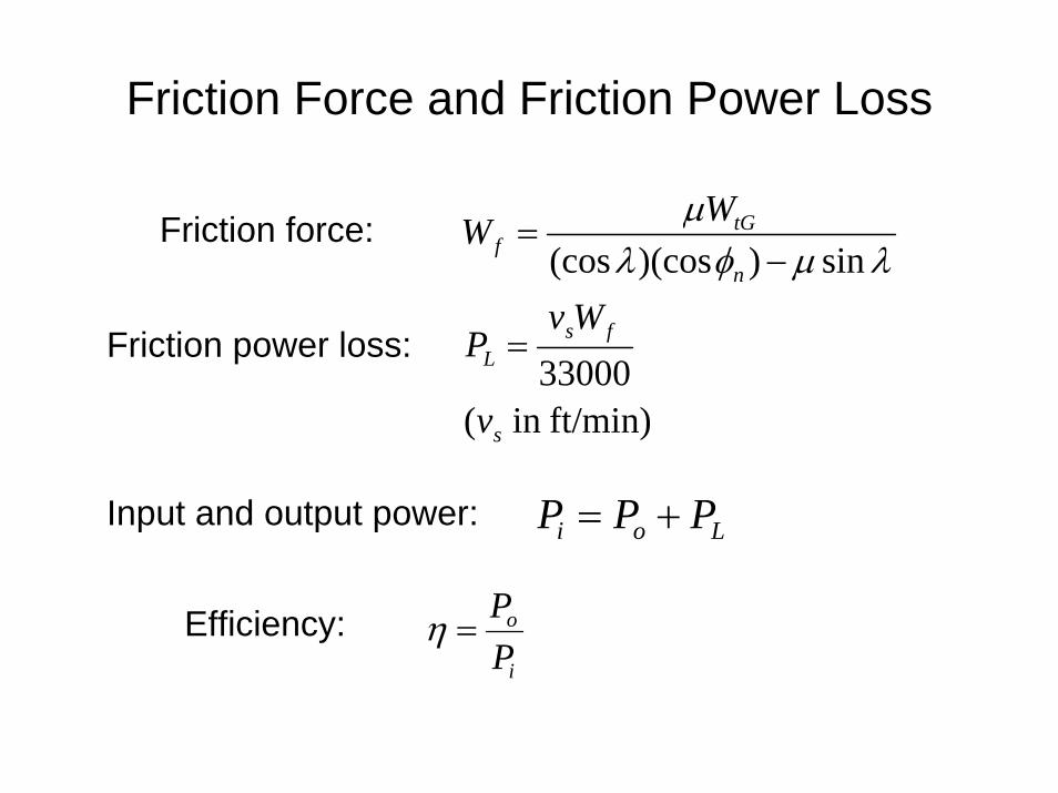
Friction Force and Friction Power Loss
ft/min)in (
33000
sin))(cos(cos
s
fsL
n
tGf
v
WvP
WW
=
−=
λμφλμFriction force:
Friction power loss:
Input and output power: Loi PPP +=
Efficiency:i
o
PP
=η
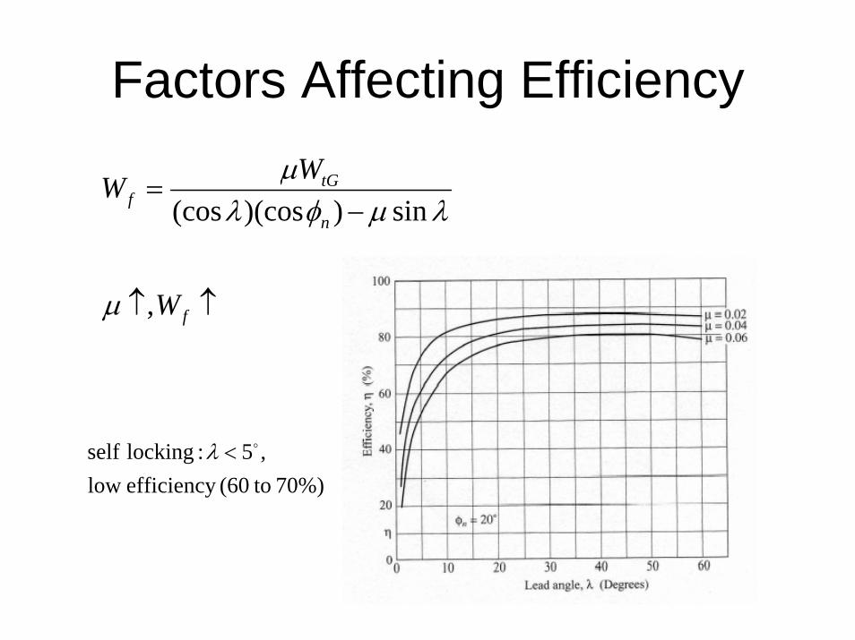
Factors Affecting Efficiency
↑↑
−=
f
n
tGf
W
WW
,
sin))(cos(cos
μ
λμφλμ
70%) to(60 efficiency low,5 :locking self o<λ
Worm Gear Stress Analysis
• Only worm gear is analyzed since threads are more durable and made from a stronger material
• Different from other types of gears• Bending stress analysis• Surface durability
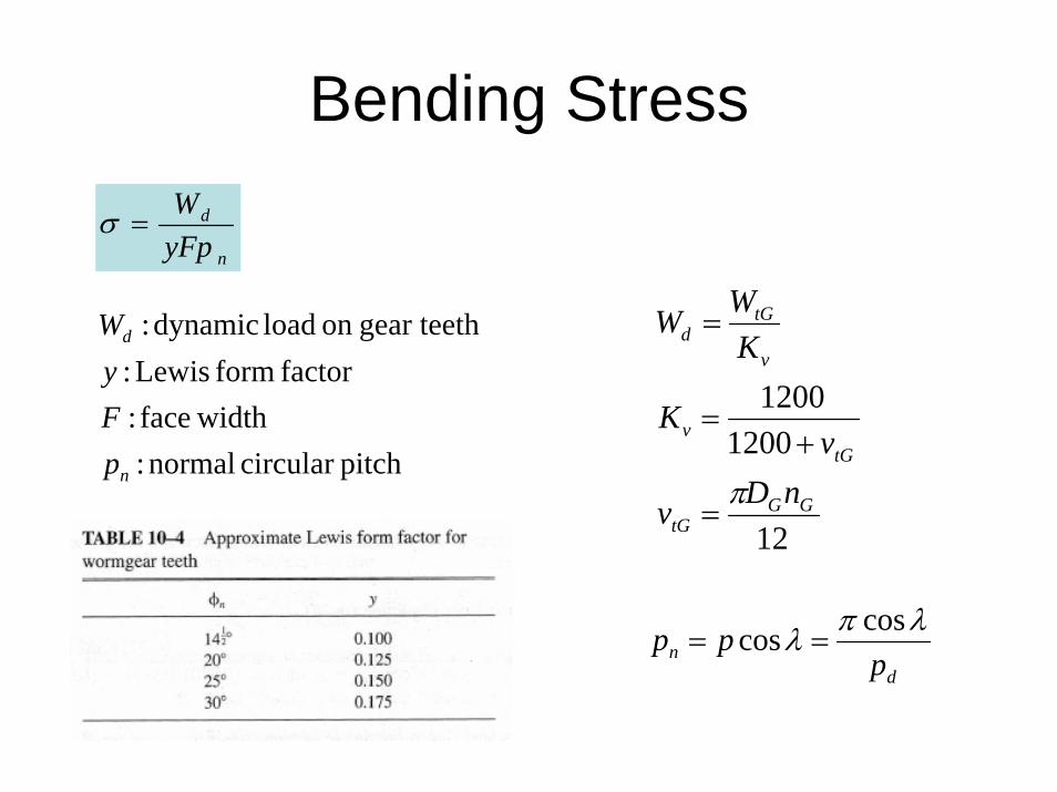
Bending Stress
n
d
yFpW
=σ
pitchcircular normal : widthface :
factor form Lewis :gear teethon load dynamic :
n
d
pFyW
dn p
pp λπλ coscos ==
12
12001200
GGtG
tGv
v
tGd
nDv
vK
KWW
π=
+=
=
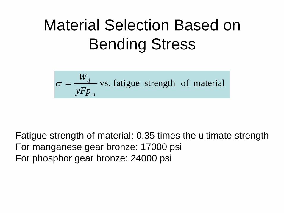
Material Selection Based on Bending Stress
material ofstrength fatigue vs.n
d
yFpW
=σ
Fatigue strength of material: 0.35 times the ultimate strengthFor manganese gear bronze: 17000 psiFor phosphor gear bronze: 24000 psi
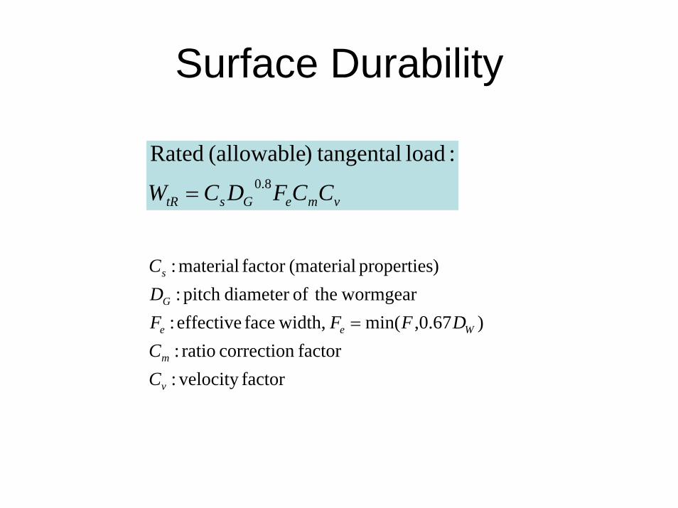
Surface Durability
vmeGstR CCFDCW 8.0
:load tangental)(allowableRated
=
factor velocity :factor correction ratio :
)67.0,min( width,face effective : wormgear theofdiameter pitch :
)properties (materialfactor material :
v
m
Wee
G
s
CC
DFFFDC
=
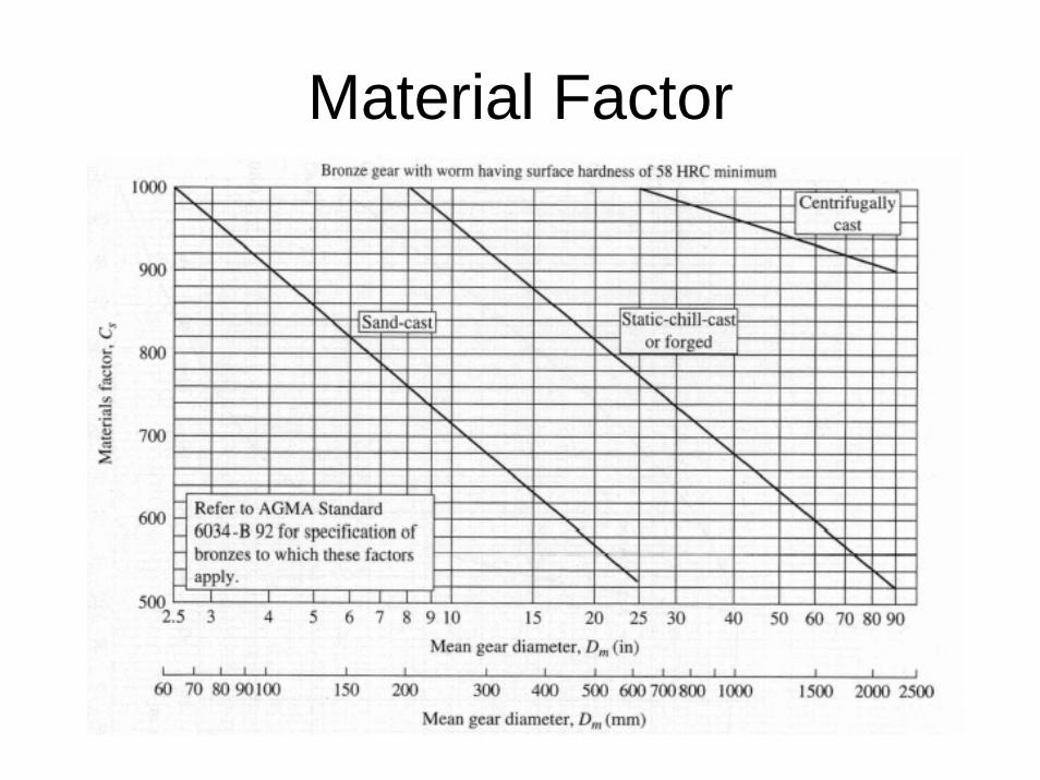
Material Factor
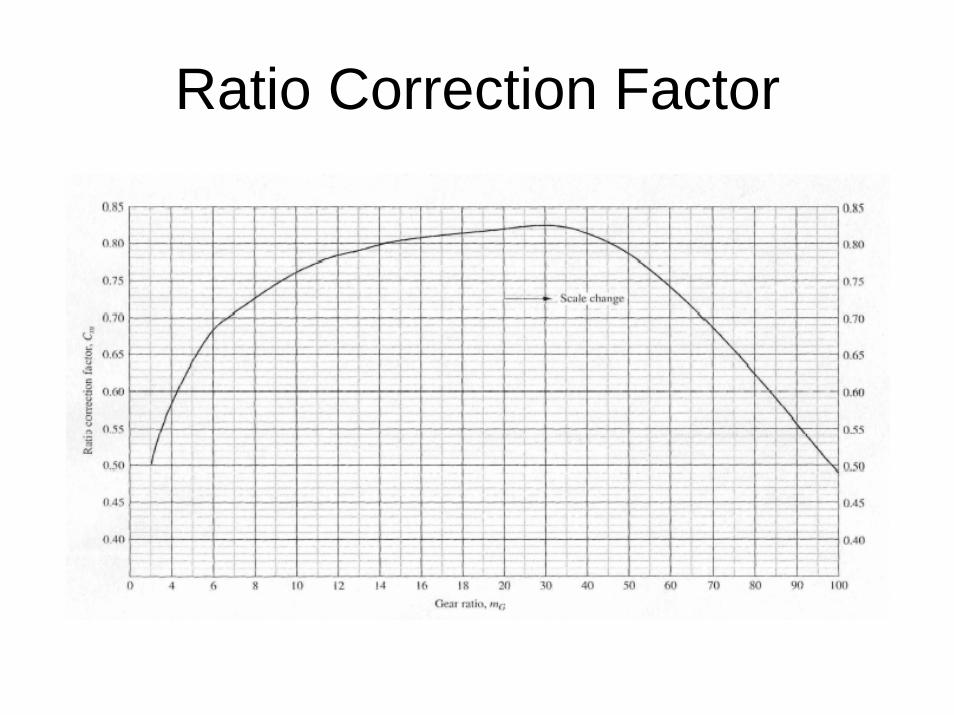
Ratio Correction Factor
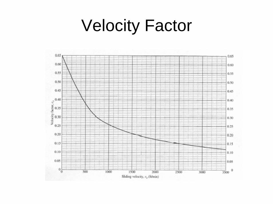
Velocity Factor
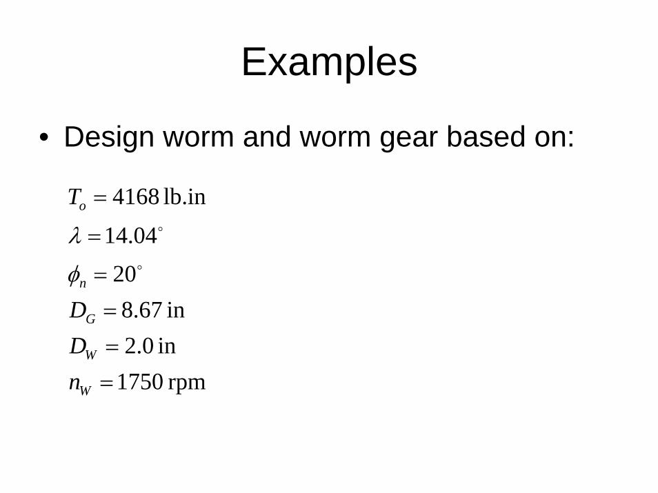
Examples
• Design worm and worm gear based on:
rpm 1750in 0.2in 67.8
2014.04
lb.in 4168
====
=
=
W
W
G
n
o
nDD
T
o
o
φ
λ


![[3] involuteΣ Worm Gear Design System · [3] involuteΣ Worm Gear Design System Fig. 3.1 involuteΣ Worm Gear Design System 3.1 Introduction The involuteΣ Worm Gear Design System](https://static.fdocuments.us/doc/165x107/5eadff0184c9a55408434a64/3-involute-worm-gear-design-3-involute-worm-gear-design-system-fig-31.jpg)