ENTC 1110 OBLIQUE PICTORIALS. Oblique pictorials are another method of creating a pictorial sketch...
45
ENTC 1110 OBLIQUE PICTORIALS
-
Upload
eleanore-hudson -
Category
Documents
-
view
224 -
download
1
Transcript of ENTC 1110 OBLIQUE PICTORIALS. Oblique pictorials are another method of creating a pictorial sketch...

ENTC 1110
OBLIQUE PICTORIALS

Oblique pictorials are another method of creating a pictorial sketch of an object.
Oblique sketching attempts to combine the ease of sketching in two dimensions with the need to represent the third dimension.
The front face is seen in its true shape and is square with the paper, and only the depth is drawn at an angle.

Note that the lines of projection are parallel to each other.
Oblique sketching is useful when the majority of the features are on the front face of the object.• Oblique sketching should not be used if the
object has many features (especially, circular ones) on faces other than the front.
As with isometric sketches, hidden features are not shown on most oblique sketches, unless absolutely necessary to describe the object. • Because of the difference in how the depth
dimension is drawn scaling the depth to half or two-thirds its actual size helps the visual proportions of the sketch.

Creating an Oblique Sketch
The figure shows the object to sketched. • The object is oriented so that most of the
details are represented in the front view.
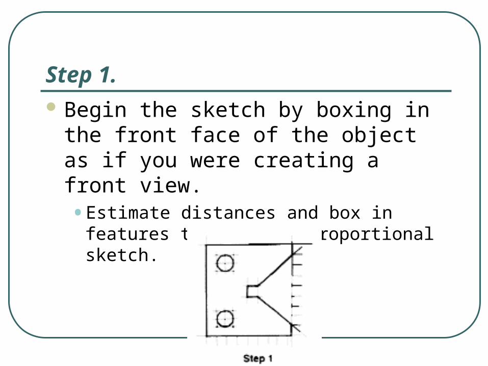
Step 1. Begin the sketch by boxing in the front
face of the object as if you were creating a front view. • Estimate distances and box in features to
create a proportional sketch.

Step 2. To view the object from the right and above, sketch
depth construction lines at an angle of 30 to 45 degrees above the horizontal and to the right of the front face.

To view the object from below, sketch the depth lines below the horizontal. • To view the object from the left side, sketch
the depth lines to the left of the front face.
• Sketch only corners that will be visible.

Estimate the distance for the depth along the sketched lines. • Full-length depth lines may make the object
look out of proportion.
• Two-thirds or one-half size depth lines will create a better proportioned sketch.

If full-size depth dimensions are used, the sketch is called a cavalier oblique. • If the depth is one-half size, the sketch is
called a cabinet oblique.

Step 3.
Draw a line between each depth mark to create the back edge of the object.• These lines are parallel to the edges of the
front view.

The next step is to determine if any part of the hole on the rear of the object can be seen from the front. • This is done by marking the locations of the centers of
the holes on the front and sketching depth lines from those center points.
• The depth is marked on the depth lines, the marks are used as centers for the back holes, and circles equal in diameter to the front circles are sketched.
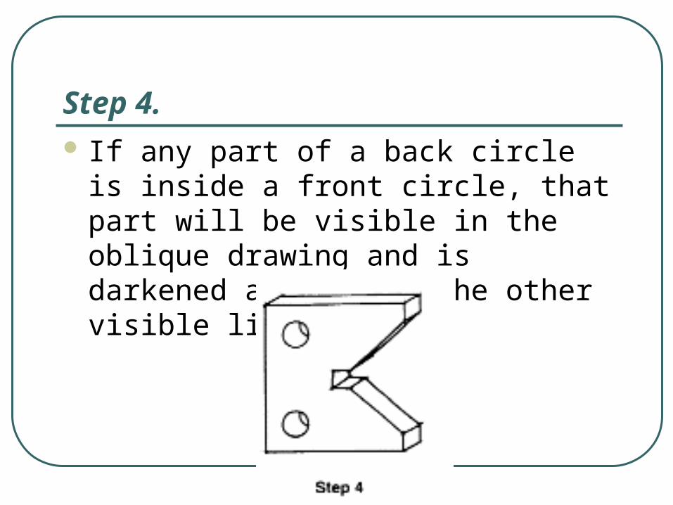
Step 4. If any part of a back circle is inside a
front circle, that part will be visible in the oblique drawing and is darkened along with the other visible lines.

Using Grid Paper to Create an Oblique Sketch
Use tracing paper over the grid to avoid grid lines in the final sketch.
The front face can be sketched much like a 2-D drawing.
The depth axis is sketched along a 45-degree line that is a diagonal of the square grid boxes.

Step 1. Count the number of squares to
determine the dimensions of the object. • For the example in the figure, the width of the
object is 12 and the total height is 15.
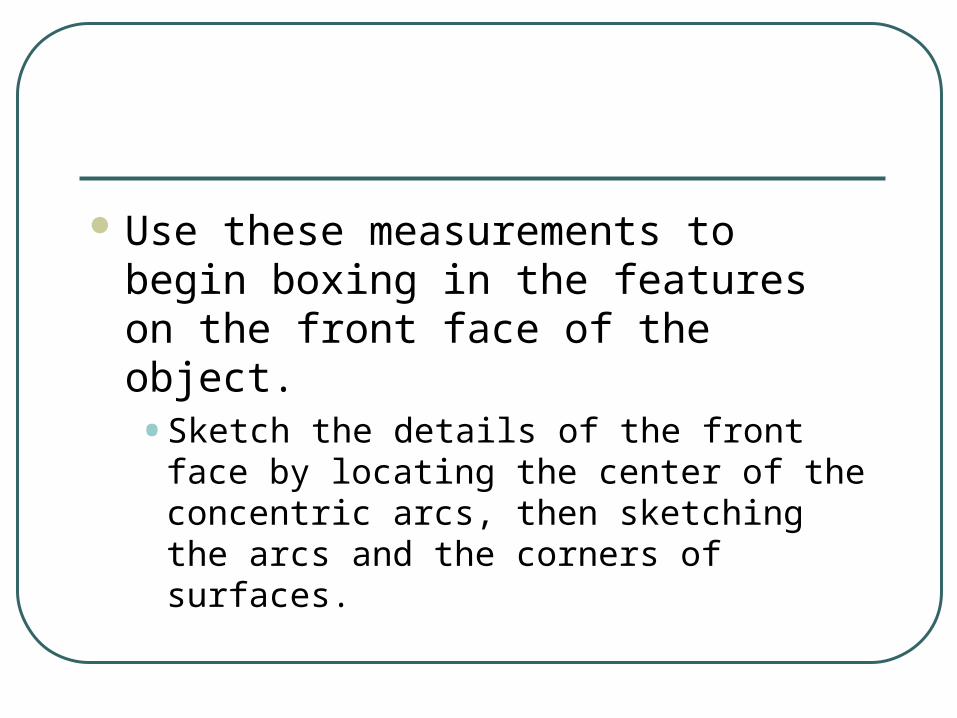
Use these measurements to begin boxing in the features on the front face of the object. • Sketch the details of the front face by locating
the center of the concentric arcs, then sketching the arcs and the corners of surfaces.

Step 2. Sketch the depth of the object by
drawing diagonals of the square grids, which are 45 degrees above the horizontal.

Make this sketch a cabinet oblique by using half the actual depth. • As with an isometric sketch, many of the
features on the front face have to be projected to the back face.
• Be careful when determining which edges or portions of edges will be hidden.

Step 3.
Darken all visible lines.
ENTC 1110
MULTIVIEW PROJECTIONS
Multiview drawings are based on parallel projection techniques and are used when there is a need to represent the features of an object more accurately than is possible with a single (pictorial) view.• A multiview drawing is a collection of flat 2-D drawings
that work together to give you an accurate representation of the overall object.
• With a pictorial drawing, all three dimensions of the object are represented in a single view.

Each view concentrates on only two dimensions of the object,• So particular features can be shown with a
minimum of distortion.
• Enough views are generated to capture all the important features of the object.

Why are’nt multiview drawings always used? • For one thing, there are the multiple views, rather than
a single view, to be drawn.
• These views must be coordinated with one another to represent the object properties.
• You have to carefully visualize the views as you sketch them, and so does the person viewing them.
• Without training and experience, you might find it hard to interpret multiview drawings.
The choice between multi-views and pictorials is often one of exact representation of features versus ease of sketching and viewing.
When creating a multiview drawing, the selection and orientation of the front view is an important first step.
The front view is chosen as the most descriptive of the object: • In addition, the object must be properly
oriented in the view. • The orientation of the object is based on its
function.

A multiview drawing should have the minimum number of views necessary to describe an object completely.• Normally, three views are all that are needed.
• However, the three views chosen must be the most descriptive ones.
• The views that reveal the most information about the design with the fewest features hidden from view.

Consider the figure.• There are six principle,
or regular views.
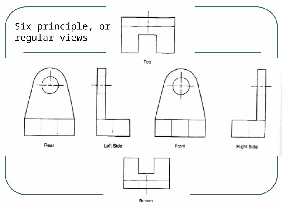
Six principle, or regular views
The previous drawing has four important features: • the hole,
• the rounded top,
• the L-shaped profile,
• and the slot cut out of the base in front.
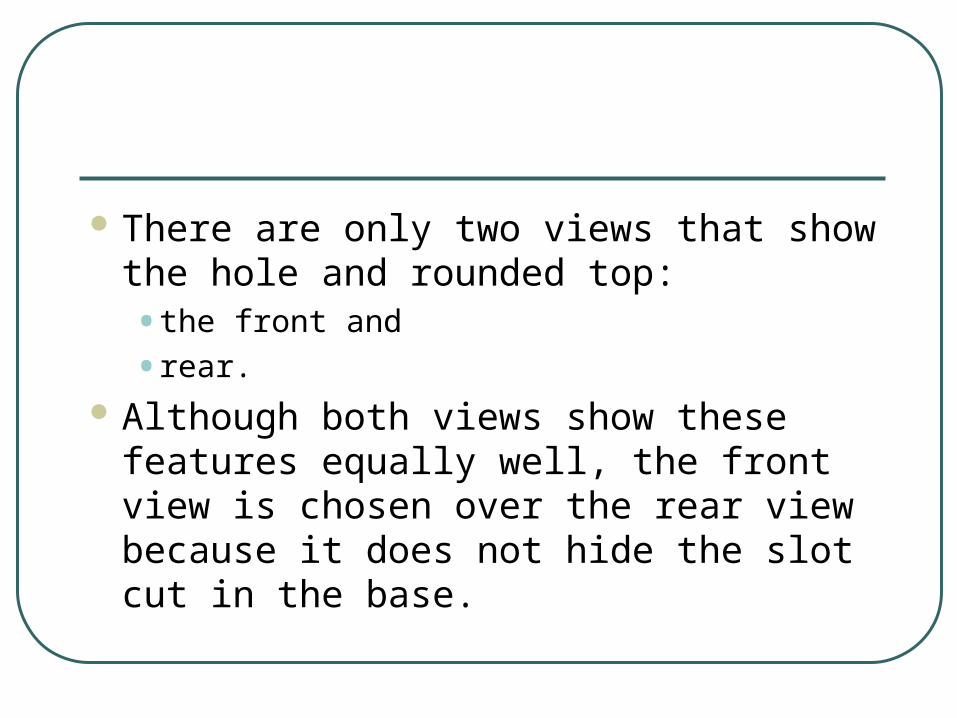
There are only two views that show the hole and rounded top:• the front and
• rear.
Although both views show these features equally well, the front view is chosen over the rear view because it does not hide the slot cut in the base.

The L-shaped profile is shown equally well in both the right and left side views, and they have an equal number of hidden features.• Although either view can be used, convention
favors choosing the right side view.

The slot is shown in both the top and bottom view.• However, the top view has fewer hidden lines,
so it is preferred over the bottom view.
The preferred views for this figure are:• front,
• top, and
• right views

Line Conventions
It is important that hidden features be represented, so that the reader of the drawing can clearly understand the object.
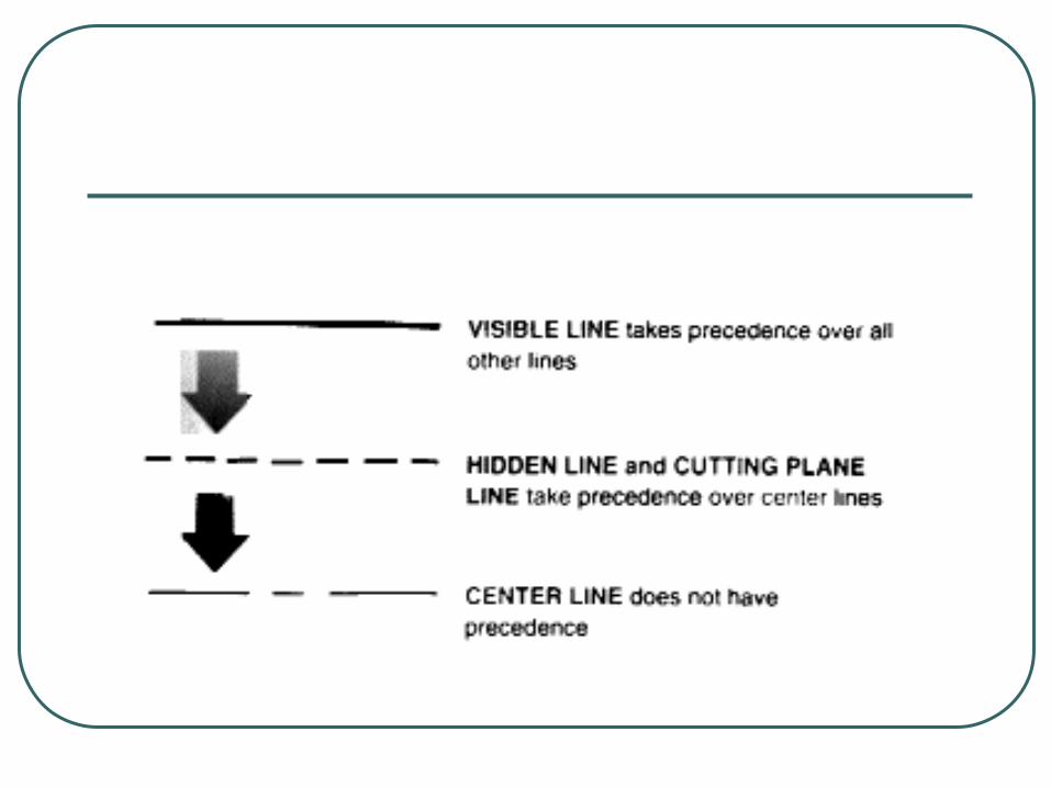

Line conventions:• There should be no gap when a hidden line intersects
a line when the feature terminates.
• Corners on hidden lines should be joined
• There should be a gap when a hidden line intersects either a visible corner or visible arc.
• Three (hidden) intersection corners, found in holes that are drilled and that end inside the object (i.e., do not go all the way through the object), should be joined.
• At the bottom of the drilled hole, the lines indicating the tip (created by the drill, which has a pointed tip) are joined.

• Hidden arcs are started on the center line or the point of tangency.
• When a hidden line passes behind a visible line (i.e., does not intersect the visible line), do not put a hidden-line dash on the visible line.
• At the point where one hidden line crosses in front of another hidden line (indicating two hidden features, one closer to the visible view than the other), use a dash for the hidden in front; that is, if the front hidden line is horizontal, use a horizontal dash at the point of crossing.

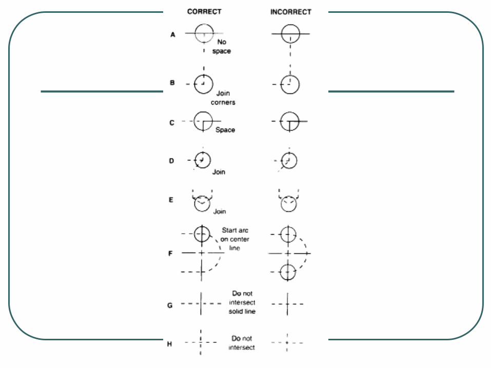

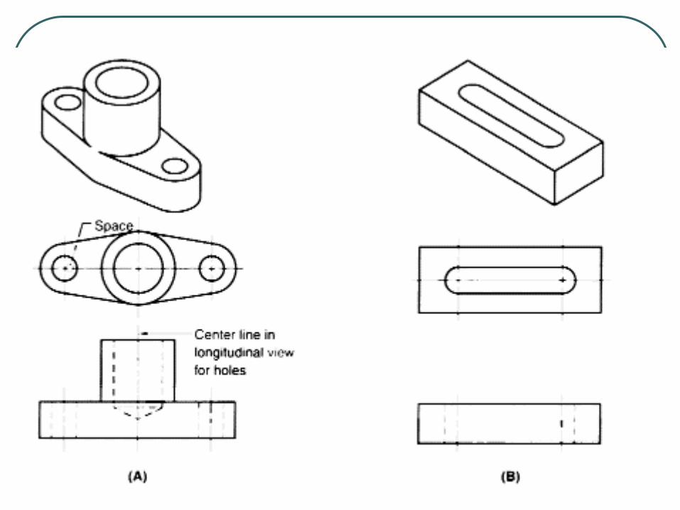
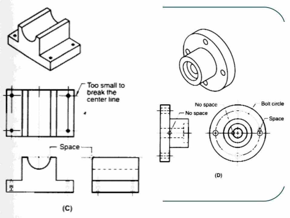
Conventional Practices for Circles and Arcs Circles are used to represent holes and the bases of
cones and cylinders. Arcs are used to represent portions of these elements, as
well as rounded corners on objects. Whenever representing a hole. cylinder, or cone on a
technical drawing, the conventional practice is to draw center Iine, which are used to • (1) locate the centers of circles and arcs,
• (2) represent the axis of cylinder, cones, and other curved surfaces: and
• (3) represent lines of symmetry.