Ensuring Successful Home Wi-Fi Deployments
57
Ensuring Successful Home Wi-Fi Deployments Bret McElwee 1
Transcript of Ensuring Successful Home Wi-Fi Deployments

Ensuring Successful Home Wi-Fi DeploymentsBret McElwee
1

Wi-Fi Standards
2

2.4 GHz5 GHz
Getting to Know the Wi-Fi Spectrum
3
2.4 GHz 5 GHz
Number of non-overlapping 20 MHz channels 3 18 (including DFS channels)
Number of non-overlapping 40 MHz channels 1 9
Number of non-overlapping 80 MHz channels 0 4
Range Better Good

2.4 GHz vs 5 GHz – A Typical Home
• 2.4 GHz averaged 21.5% interference
• 5 GHz averaged 0.3% interference
• These are results in a condominium and are fairly typical
• 5 GHz is still less congested than 2.4GHz in most locations
4
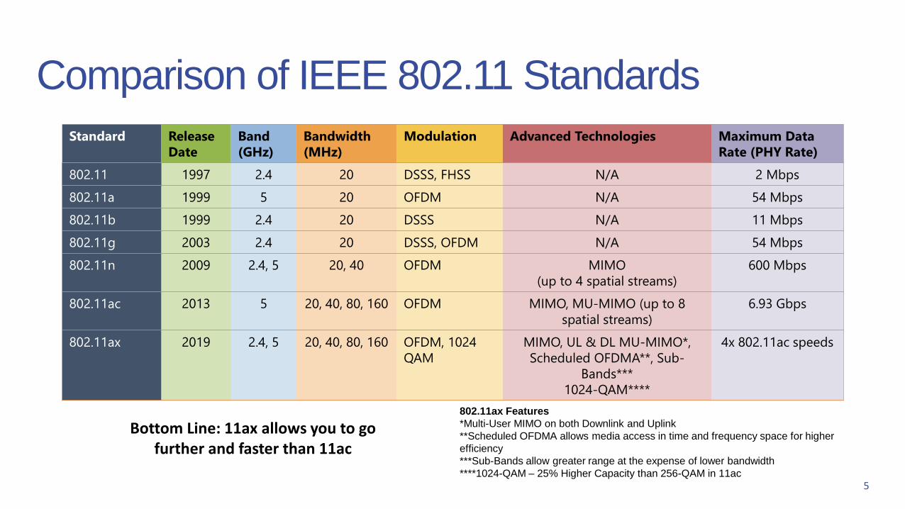
Standard Release
Date
Band
(GHz)
Bandwidth
(MHz)
Modulation Advanced Technologies Maximum Data
Rate (PHY Rate)
802.11 1997 2.4 20 DSSS, FHSS N/A 2 Mbps
802.11a 1999 5 20 OFDM N/A 54 Mbps
802.11b 1999 2.4 20 DSSS N/A 11 Mbps
802.11g 2003 2.4 20 DSSS, OFDM N/A 54 Mbps
802.11n 2009 2.4, 5 20, 40 OFDM MIMO
(up to 4 spatial streams)
600 Mbps
802.11ac 2013 5 20, 40, 80, 160 OFDM MIMO, MU-MIMO (up to 8
spatial streams)
6.93 Gbps
802.11ax 2019 2.4, 5 20, 40, 80, 160 OFDM, 1024
QAM
MIMO, UL & DL MU-MIMO*,
Scheduled OFDMA**, Sub-
Bands***
1024-QAM****
4x 802.11ac speeds
Comparison of IEEE 802.11 Standards
5
802.11ax Features
*Multi-User MIMO on both Downlink and Uplink
**Scheduled OFDMA allows media access in time and frequency space for higher
efficiency
***Sub-Bands allow greater range at the expense of lower bandwidth
****1024-QAM – 25% Higher Capacity than 256-QAM in 11ac
Bottom Line: 11ax allows you to go further and faster than 11ac

Wi-Fi Data ElementsYou can’t manage a Wi-Fi network unless you can see inside of it.
6

Why are Wi-Fi Data Elements needed?
• All support calls cost money and 10% percentage of Wi-Fi related calls require expensive truck rolls.
• To trouble shoot and manage Wi-Fi networks, it is critical to be able to see what is going on in the network.
• Self Organizing Wi-Fi autonomously reconfigures the network for optimal performance. Without Data Elements, there is no way to measure performance or see if reconfiguration has improved the performance
7
To see inside the Wi-Fi network, a foundation of
Wi-Fi network Data Elements is needed to
measure performance of the network.

Why are Wi-Fi Data Elements needed?
8
Wi-Fi Key Data Elements are used by tools such as
Calix Support Cloud Smart Check to provide a simplified
view of what is going on with client devices in the home.

6 Key Data Elements
1. Air Time Usage – used by Access Points and Clients
2. Client PHY Rates: Maximum Capability and Actual
3. Received Signal Strength (RSSI)
4. Retransmitted Packet Rates
5. Dropped Packet Rates
6. Site Scans (Measurements of all detected neighboring Access Points and Channels)
9

Data Element 1: Air Time Usage
10
Free Air Time (green)
‘gas’ left in the ‘tank’.
No Free Air Time
Interference (red)
large spike = ‘tank’ is empty.
The chart indicates how
air time is being used.

Data Element 2 - 3: Client PHY Rates / RSSI
11
Poor Client PHY rates or low Received Signal Strength Indicator (RSSI) can result in poor performance for the user applications.
• May be due to legacy Wi-Fi STA technology, low signal strength, distance or walls between STA and AP, or interference.
• PHY rate needed depends on applications, IoT may not need high PHY rates, however 4K Video Streaming does.
High PHY Rate
Low RSSI
Low PHY Rate

Data Element 4 - 5: Dropped and Retransmitted Packet Rates
12
Monitor Packet Error and Retransmission rates for an indicator of the overall quality of the connection.
• High packet retransmission rates can be considered early warning signs of poor Wi-Fi connections.
• Having the ability to measure both packet error rate and retransmission rate is essential.
High Retransmission Rate
High Dropped Packets

Data Element 6: Site Scan
13
Busyness
Neighboring SSIDs
Current Channel (11)
[Dotted line box height does
not represent power level]
A Site Scan provides a visual representation of local Wi-Fi environment.
The Calix site scan algorithm recommends the best available channel
by analyzing both detected neighbors and channel busyness.
The left column does not
represent power levels on the
GigaCenters or gigaSPIREs.

Calix Industry Initiative – Wi-Fi Alliance Data Elements
Standardize a Set of Key Wi-Fi Data Elements in the
WFA:
• Dec. 2017: Wi-Fi Alliance starts Task Group for Data
Elements based on CableLabs/Calix/Nokia proposal
• Sept 2018: Certification wave #4 successfully
completed
• Oct. 2018: Data Elements Technical Specification
completed
• End 2018: Start release 2.0 of WFA Data Elements
14
Why should you care? A: With a standard set of DE's
an operator can ask vendors to comply and any
cloud software will interoperate with the devices

Chipset Tests
• Any Wi-Fi device, including the 8x8 11ax AP, is capped by FCC transmit power limits, and a 3x3 Macbook 11ac client cannot receive more than 3 spatial streams
• Can the Macbook performance still be improved with the 8x8 AP?
15
8x8 UDP Downlink
8x8 TCP Downlink
4x4 UDP Downlink
4x4 TCP Downlink
Downlink Throughput to Macbook Pro 3x3
+6dB (1 extra wall)
+4dB
Thro
ugh
pu
t (M
bp
s)
Attenuation (with steps in dB)
+80Mbps
• Yes, twice as many transmit antennas reduces the power per radio chain, improving RF fidelity at high data rates
• Yes, receiver benefits from 8x8 diversity vs 4x4 (no FCC limits on sensitivity)

Wi-Fi Test Chamber
16
• Calix test environment has combined the best of both worlds, no cables yet repeatable and free of external interference
Two major ways of testing Wi-Fi performance
1. Cabled testing from AP to client –repeatable but not realistic and requires removal of antennas on AP and client
2. Over the air (OTA) – Allows realistic testing with antennas but suffers from outside interference and is less repeatable

• Real data throughput rate is never has high as the PHY rate
Wi-Fi Test Chamber – 4x4 Antenna
17
Real Packet rate is about 50% of the reported PHY rate for the GigaCenter

• Real data rate with 8x8 device is closer to the PHY rate
Wi-Fi Test Chamber – 8x8 Antenna
18
GigaSPIRE data rate is 80% of PHY rate

• GigaSPIRE achieves higher peak data rates of > 600 Mbps (red) and has virtually no areas of the home that are less than 100 Mbps (blue).
• Conditions• TCP Throughput Testing
• Client used in testing: MacBook Pro 3x3 MIMO 802.11ac
• Stucco on wire mesh exterior walls
• 50-60 Test Points per floor
Wi-Fi Test Home Throughput Tests - Downstairs
19
GigaCenter GigaSPIRE

• GigaSPIRE achieves upstairs peak data rates of > 500 Mbps (orange) and has virtually no areas of the home that are less than 100 Mbps (blue).
• Conditions• TCP Throughput Testing• Client used in testing: MacBook
Pro 3x3 MIMO 802.11ac• Stucco on wire mesh exterior walls• 50-60 Test Points per floor
Wi-Fi Test Home Throughput Tests - Upstairs
20
GigaCenter GigaSPIRE

Wi-Fi Backhaul Performance
21
• GigaCenter Backhaul PHY Rate –700 Mbps
• GigaSPIRE Backhaul PHY Rate –1300 Mbps
GigaSPIRE backhaul provides the closest thing yet to a “Wireless Ethernet Cable”

Mesh-Enhanced Carrier Class Wi-FiWhy are more than one Access Points needed in some homes?
22

Wi-Fi Has a Physics Problem: Attenuation
23
GigaCenter
iPhone 6S
802.11ac
2x2 MIMO
80 MHz Bandwidth
802.11ac
4x4 MIMO
80 MHz Bandwidth
Access Point
Wall 1 Wall 2 Wall 3
3 Walls (~27dB) attenuation
Peak PHY rate – 2x2 client
~50 Mbps Throughput

Wi-Fi Has a Physics Problem: Attenuation
24
GigaCenter
iPhone 6S
802.11ac
2x2 MIMO
80 MHz Bandwidth
802.11ac
4x4 MIMO
80 MHz Bandwidth
Access Point
Wall 1 Wall 2 Wall 3
~264 Mbps
Throughput
~50 Mbps
Throughput
Mesh
2 Walls (~18dB) 1 Wall (~9dB)
3 Walls (~27dB attenuation)
Peak PHY rate
400 Mbps (2x2)
Peak PHY rate 50Mbps (2x2)
Peak PHY rate
800 Mbps (4x4) However…..

Access Network Use Cases
25

HSI Untagged
High-Speed Internet Only
HSI Tagged (4)
Servers /
ServicesCore
Router Access Network
HSI Tagged (4)
700GE
Use Case 1: Internet Only• Routed Internet Only
• Single VLAN
Mobile Phone
Laptop
Printer
Wireless Connection
26
gigaSpire

HSI Tagged (4)
IPTV Tagged (991)
High-Speed Internet and L2 IPTV
IPTV Tagged (991)
Servers /
ServicesCore
Router Access Network
HSI Tagged (4)
Wired 2.4 GHz Wireless Connection
700GE
gigaSPIRE
Use Case 2: HSI and APAS L2 IPTV• Separate VLANs for HSI and APAS
• Any Port, Any Service (APAS) option for L2 IPTV Deployments
• Used for Minerva, Innovative, and Conklin
• Supports up to 8 set-top boxes.
Mobile
Phone
Laptop
Light Set-
top box
DVR
Set-top box
Desktop
SwitchRouter
Set-top
box
IPTV SSID 5 GHz Wireless Connection
27
HSI Untagged
IPTV Tagged (991)RGL2 Bridge

HSI Untagged
IPTV Tagged (991)
HSI Tagged (4)
IPTV Tagged (991)
High-Speed Internet and L3 IPTV
IPTV Tagged (991)
Servers /
ServicesCore
Router Access Network
HSI Tagged (4)
700GE
gigaSpire
Use Case 3: HSI and L3 IPTV• Routed Internet
• Routed IPTV w/option-121 used to facilitate unicast
traffic over the video service WAN VLAN
• Used for Mediaroom and Minerva 5.7+ deployments
• Supports up to 8 set-top boxes.
Mobile Phone
Laptop
Printer
IPTV and
Set-top Box
Wireless Set-top
Boxes
Wired 2.4 GHz Wireless Connection IPTV SSID 5 GHz Wireless Connection
28

HSI and IPTV
Untagged
Set-top box
Set-top box
High-Speed Internet and IPTV 1 VLAN
HSI and IPTV
Tagged (4)
Servers /
ServicesCore
Router Access Network
HSI and IPTV Tagged (4)
700GE
gigaSpire
Use Case 4: Internet and IPTV• Routed Internet and IPTV
• Single VLAN
• Used for Internet/Mediaroom deployments
Mobile Phone
Laptop
Printer
29
2.4 GHz Wireless Connection IPTV SSID 5 GHz Wireless Connection

The Wireless NetworkBest Practices
30

SSID Best Practices
• Enable only SSIDs necessary to connect to
the wireless network.
• Define a naming convention that works best in
your organization.
• Hiding SSIDs does not secure the wireless
network.
• Educate subscribers about naming SSIDs and
how to avoid making SSIDs obvious to
neighbors.
• Example: Homer and Marge’s House
• Example: Bart’s Wi-Fi
• Educate subscribers about not sharing their
SSID (and passphrases) with neighbors.
31
Good
SSID Name
Bad
SSID Name

Securing the Wireless Network
• WPA2 Personal provides the best security
currently available.
• AES replaces TKIP as the best secure
option. It uses up to 256-bit encryption to
secure data.
• Create strong passphrases
(passwords)
• Use a mix of upper and lower case letters with
numbers and special characters.
• Spaces, periods, underscores, and asterisks
are allowed in naming passphrases.
• MAC Authentification
• Not enough to secure a network.
32

Maximizing Wireless Network Performance
• Perform Site Observations / Site Surveys
• Determine Access Point Location
• Configuring Wireless Settings on the Access Point
• Perform Wi-Fi Analysis
33

Site Observations
• Locate the fiber/coax cable in the home.
• Look for interferers in and around the home.• Cement and brick material
• Double-pane and tinted glass
• Mirrors
• Wireless sound bars
• Baby monitors
34

Access Point Location
• Place access points high and
in the center of the home whenever
possible.
• Avoid placing the main access points
in the basement.
• View Wi-Fi Analyzer tools to check
Wi-Fi usage.
• Example: Wi-Fi Analyzer
• Example: Wi-Fi Smart Check and current
Air Time Analysis in Calix Support Cloud
35

Determine the Best Location
• Use Wi-Fi Analyzer to
determine the best location.
• View real-time air time
utilization as you move the
device around.
• View air time utilization for
both 2.4 and 5 GHz.
Wi-Fi Analyzer is located in the Support
area of the EWI of GigaFamily Devices
36

Configuring Wireless Settings on the Access Point
• Isolate legacy devices from hogging
air time away from modern devices by
removing 802.11b from the Mode to
prevent old devices from connecting.
• In some rare cases, it’s optimal to
reduce the 5 GHz bandwidth since the
wider the signal bandwidth, the
shorter the distance covered.
• Allow devices to auto-select the best
channel that is less crowded with the
least interference.
• For the 5 GHz radio, when possible
allow use of additional channels in the
5 GHz band (DFS Channels).
2.4 GHz Radio
5 GHz Radio
37Ex. gigaSPIRE EWI

Wi-Fi Analysis – Today
View neighboring devices using Calix Support Cloud.
38
View subscriber devices and Wi-Fi performance using
Smart Check Client Devices in Calix Support Cloud.

Wi-Fi Analysis – Tomorrow
39MAP - Micro-services Aggregation Platform
MAP
Home Network Security Parental Controls TelemetryVoice Home Automation
IVR
TR-069
WSS
IVR – Interactive Voice Response
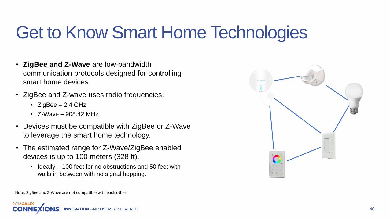
Get to Know Smart Home Technologies
• ZigBee and Z-Wave are low-bandwidth
communication protocols designed for controlling
smart home devices.
• ZigBee and Z-wave uses radio frequencies.
• ZigBee – 2.4 GHz
• Z-Wave – 908.42 MHz
• Devices must be compatible with ZigBee or Z-Wave
to leverage the smart home technology.
• The estimated range for Z-Wave/ZigBee enabled
devices is up to 100 meters (328 ft).
• Ideally – 100 feet for no obstructions and 50 feet with
walls in between with no signal hopping.
40
Note: ZigBee and Z-Wave are not compatible with each other.

Smart Home Topology
41
Controller
In-Wall Fan
Controller
Smart Light
Bulb
Outdoor
Surveillance Cam
Smart Home
Control Panel
Flood
Monitor
• A Z-Wave network contains at least
one controller.
• Devices connected to the controller
are called nodes.
• The controller allow devices (nodes)
to join or be removed from the
network.
• All non-battery powered devices are
used to create a wireless self-
organizing network.
• Up to 232 devices, nodes can be added
to the Z-Wave Network.
• ZigBee has no concrete limit.

Calix Smart Home Topology
42
Controller
Home ID CALX123
Node ID 4
In-Wall Fan
Controller
Node ID 2
Outdoor
Surveillance Cam
Node ID 5
Smart Home
Control Panel
Node ID 1
Flood
Monitor
• Controllers contain unique IDs that are
not labeled the same. The unique IDs
are called Home IDs.
• Home IDs prevent you from being able to
control your neighbor’s devices.
• Nodes contain unique IDs.
IDs cannot be labeled the same.
• Node IDs ensure that the signal goes to
the device it is intended for.
• AES 128-bit encryption.
Node ID 3
Smart Light
Bulb

Recommended Installations
• Calix Smart Home is intended for
single-family units.
• Calix Smart Home can be deployed in
multi-dwelling units, but separate
networks must be setup for each family.
• If used in a high-rise, the building materials
are often not RF-friendly.
• Calix Smart Home is not recommended
for large commercial or industrial
networks.
43
Single-Family Units
Multi-Dwelling Units

What can Impact Smart Home Performance?
• Path loss is the loss of signal. It is also known
as attenuation.
• Causes of path loss:
• Distance
• Obstacles and the materials they are made of.
• Performance of the radio frequency
(RF) signal
• Key Smart Home scenarios installers should know.
• Vacuum Fade
• Shadow
• Reflection
44
Smart Lamp
Wall
Distance

Building Materials and Path Loss
Material Thickness Worst Case
Signal Attenuation
Glass .25 inch 10%
Drywall < 4 inch 30%
Wood 3 inch 30%
Stone 10.5 inch 70%
Concrete 4 inch 70%
Concrete 8 inch 90%
Reinforced Concrete
4.5 inch 95%
Concrete 12 inch 98%
45

Vacuum Fade
• Vacuum Fade occurs when a device fails or if a device was plugged into a switch outlet and someone turned off the switch.
• There are two stages used to address vacuum fade.
• Anticipate• Detect problem areas beforehand.
• For new home instructions, determine if an outlet can be added.
• Can a Z-Wave/ZigBee outlet be added insteadof a plug-in module?
• Can you find a module with a pass-through plug?
• Diagnose• Ask the subscriber about any failures and what
changes they made before the failures.
46

Shadows
• A shadow occurs when the attenuation of a signal going through building material create an RF dead spot.
• Installers should identify shadows.
• Installers can add repeaters to strengthen Z-Wave mesh networks to eliminate shadows.
47
Shadow
Coverage
Area

Reflection
• Reflections occur when the wireless signal bounces off an object.
• Reflections are not avoidable and can cause interference due to time delays of the reflection, also known as multi-path or phase interference.
• The solution is to add always-on devices to strengthen the self-organizing mesh network.
48
Reflection

Calix Wireless Network Solution Overview
49

Calix GigaFamily
50
800G
804M
GS2026E GS2020E
GM1020

800G GigaCenter
The image shown is an 854G GigaCenter. The 844G does not contain an RF overlay.
2.4 GHz and 5 GHz Wi-Fi
USB Port
Reset button
Ethernet Ports
RJ Connectors
Power Connector
RF Video Connector
WPS button
Your Company’s Logo
LED Indicators
51

804Mesh Satellite Specifications
Dual Band Wi-Fi Range Extender
• 2.4 GHz 802.11 b/g/n 2x2 MIMO, high-
power
• 5 GHz 802.11 a/n/ac 4x4 MU-MIMO,
implicit/explicit dynamic beamforming
• IEEE 802.11v BSS Transition Management
• Wired: 10/100/1000 BASE-TX Ethernet
Port, RJ-45 connector
Interoperability
• 800G, 844GE, and 844E
TR-069 remote management
• TR-098 Internet Gateway Device Data
Model
Wi-Fi Alliance Certified
52
WPS button
Reset button
Power Connector
Ethernet Port
LED Indicators
2.4 GHz and
5 GHz Wi-Fi

gigaSPIRE
WPS
Reset
LAN Port
WAN Port
USB 3.0 Port
Sound Jack
Power
The gigaSPIREs Blast and Max share the same physical features except the Blast does not have a sound jack and there are no controls at the top.
Top View
53
Action Button
Volume Up
Volume Down
Mute

gigaSPIRE Comparison
54
GS2026E GS2020E
WAN 10/100/1000 Ethernet or Wi-Fi 10/100/1000 Ethernet or Wi-Fi
LAN 10/100/1000 Ethernet 10/100/1000 Ethernet
Wi-Fi5 GHz – 802.11ax/ac/n - 8x8 MIMO 2.4 GHz – 802.11ax/g/n - 4x4 MIMO
5 GHz – 802.11ax/ac/n - 8x8 MIMO 2.4 GHz – 802.11ax/g/n - 4x4 MIMO
IVR (Interactive Voice Recognition)
Yes N/A
IoT ZigBee / Z-Wave N/A
Bluetooth BT / BLE N/A
POTS N/A N/A
Dimensions 5” x 5” x 9” 5” x 5” x 9”

gigaMESH
55
WPS
Reset Button
LED Indicator
WAN/LAN Port
AC Power

gigaMESH Specifications
Dual-band Wi-Fi Range Extender
• 2.4GHz 802.11b/g/n
• 2x2 MIMO
• 5GHz 802.11a/n/ac
• 2x2 Downlink (DL) MU-MIMO
• Implicit/explicit high-power, dynamic beamforming
Wired
• 10/100/1000 /Base-TX Ethernet Port
• RJ-45 connector
Wi-Fi multimedia (WMM)
Power: 2-pin wall socket plug-in
Wi-Fi Alliance Certified
56
GM1020

Questions?
57