Ensuring capacity for future wired and wireless access network · •ACCESS: From a few kbit/s to...
45
Ensuring capacity for future wired and wireless access network Capacity bottlenecks and resource management problems in (current and) future networks and how we might limit the impact and how we might limit the impact Lars Dittmann Network technology and service platform group Communication technology cluster
Transcript of Ensuring capacity for future wired and wireless access network · •ACCESS: From a few kbit/s to...

Ensuring capacity for future wired and wireless access network
Capacity bottlenecks and resource management problems in (current and) future networks and how we might limit the impactand how we might limit the impact
Lars DittmannNetwork technology and service platform group
Communication technology cluster

Access network of the past
Communication Cluster 2009 v12 DTU Fotonik, Danmarks Tekniske Universitet

Recent trends in communcation networks
• Migrate service intergation towards using the IP protocol family
• Merging of ”many” networks in to one (or fewer)
• Increased capacity (HSDPA, LTE, ADSL2+, VDSL, FTTx)(HSDPA, LTE, ADSL2+, VDSL, FTTx)
• Combine technologies to achieve higher total capacity (4G?!)
• Change in traffic pattern due new service architecture

Network reference topology
Access
Communication Cluster 2009 v14 DTU Fotonik, Danmarks Tekniske Universitet
Access
Access
Access
Core network
Gateway
Gateway
Gateway
Gateway

Network evolution in different domains/areas
Communication Cluster 2009 v15 DTU Fotonik, Danmarks Tekniske Universitet

Wireless data evolution
Communication Cluster 2009 v16 DTU Fotonik, Danmarks Tekniske Universitet
Source: NSN
Capacity growth in access networks• ACCESS: From a few kbit/s to several Mbit/s in about 10 years –and soon Gbit/s (grown 1000-10000 times in capacity)
• CORE: From several Mbit/s to few Gbit/s in 10 years (grown 100 times in capcity).
• IMPACT on traffic engineering: hard to plan – more sophisticated control required to ensure high utilisation.
• IMPACT on transmission techniques: Wired access first to use
Communication Cluster 2009 v17 DTU Fotonik, Danmarks Tekniske Universitet
• IMPACT on transmission techniques: Wired access first to use more advanced modulation/multiplexing techniques (and poor frequency bands) – wireless/mobile next to adopt OFDMA to increase bandwidth efficiency – and now even optical core networks is adopting OFDM and QAM coding (despite several THz of good frequency band)
- has capacity requirement grown faster than expected??

NO – capacity growth is slower than expected• 25 years ago a strategic plan for Europe was 155/622 Mbit/s to all residential subscribers by the year 2000.
• 25 years ago broadband was a network capable of handling services that requires more than 2 Mbit/s (defined in 1984).
- what happened???
Communication Cluster 2009 v18 DTU Fotonik, Danmarks Tekniske Universitet
• TV was not transformed into digital format as early as possible• ADSL was “discovered” and offloaded the phone network.• Lack of consensus for broadband strategy (and still lacking)

Driving force: Beyond HDTV
576i
1080p
4 Mb/s
15 Mb/s
Communication Cluster 2009 v19 DTU Fotonik, Danmarks Tekniske Universitet
“4K”
15 Mb/s
> 200 Mb/s
1960 2005 2025?
How we deliver this service to the end-user? High-capacity + future-proof requirements.

“4K”= any new format with 8M+ pixel per frame
Communication Cluster 2009 v110 DTU Fotonik, Danmarks Tekniske Universitet
Source: C.T.A.M. de Laat, ECOC 2008
How we deliver this service to the end-user? High-capacity + future-proof requirements.

But 4k video is not the final step!
Communication Cluster 2009 v111 DTU Fotonik, Danmarks Tekniske Universitet

Needed consideration for future network• We can do it the traditional way– but does it make sense?
• Resources must be used more efficient
• Network operation must be more simple (lower layer operation when possible)
Communication Cluster 2009 v112 DTU Fotonik, Danmarks Tekniske Universitet
when possible)
• Intelligence must be more (and isolated) to the edges
• Exploit user behaviour in information retrieval and distribution (e.g. opportunistic networks)
• Power consumption must be an important design parameter

IP router power consumption vs capacity
Communication Cluster 2009 v113 DTU Fotonik, Danmarks Tekniske Universitet

ICT power consumption might not be a problem now – but…..
Communication Cluster 2009 v114 DTU Fotonik, Danmarks Tekniske Universitet
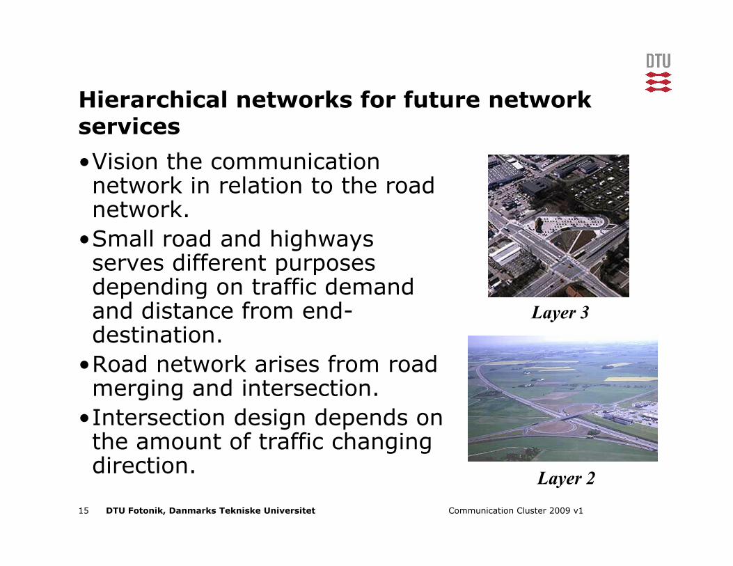
Hierarchical networks for future network services
•Vision the communication network in relation to the road network.
•Small road and highways serves different purposes depending on traffic demand
Communication Cluster 2009 v115 DTU Fotonik, Danmarks Tekniske Universitet
depending on traffic demand and distance from end-destination.
•Road network arises from road merging and intersection.
•Intersection design depends on the amount of traffic changing direction.
Layer 3
Layer 2

Simplified core network – intelligence only at edges
Communication Cluster 2009 v116 DTU Fotonik, Danmarks Tekniske Universitet

Long term goal – optical packet switching
2.5 Tbit/s
Communication Cluster 2009 v117 DTU Fotonik, Danmarks Tekniske Universitet
Optical
Packet switch

Power/bandwidth issues• Around 2/3 of power consumption in routers a due to IP-header processing -> – Minimize number of routers passed – not the same a number of nodes.
– Store and process at source/edges where processing is done anyhow and at lower rates.
– Exploit intelligent storing and alternative communication channels
Communication Cluster 2009 v118 DTU Fotonik, Danmarks Tekniske Universitet
– Exploit intelligent storing and alternative communication channels
• Two case stories: – Opportunistic networking (mobile Peer2peer)– Increase use of layer 2 and layer 1 nodes.

Case #1Opportunistic podcasting
Mobile P2P communication - to exploit user behaviour and offload access network

Motivation-Mobile P2P Arcitechture
Communication Cluster 2009 v120 DTU Fotonik, Danmarks Tekniske Universitet
Figure (left) shows the content distribution in a hybrid network and hybrid content provider scenario. Some nodes are connected to wireless LAN or 3/4G Cellular, some are not. Nodes can be any moving objects such as pedestrians, and all kind of vehicles. Firstly, content is disseminated from a content server over the Internet to users that are connected to wireless access networks e.g. wireless LAN access points or cellular base station. Secondly, content is also disseminated to users over opportunistic contacts during user mobility or vehicle mobility in a peer-to-peer manner. In terms of content source, besides professional content provider in the Internet, it becomes popular mobile users publish their personally featured content to all other users by both the infrastructure network or opportunistic direct contact with other users. Figure (right). The protocol stack of mobile peer-to-peer network is shown in figure 2. In contrast to traditional TCP/IP architecture, our system does not require network layer functions, as the classic topology-based routing function is replaced by an opportunistic forwarding and caching function at the application layer. The cache of mobile device is divided into public and private cache which stores public interest content and private interest content respectively. Data forwarding and cache management, as the key function of our system, implements the peer-to-peer data dissemination protocol and manages the all resources of mobile device such as cache, battery, and network resources such as node content opportunity. It is the core of the thesis. Transport layer is in charge of the fragmentation of application data into smaller data chunks such that data chunk can be downloaded in a short contact of node meeting. Forward Error Correction (FEC) function is also provided at transport layer to provide reliable data transfer in a single hop wireless link. Data and PHY layer can be any wireless technology, Bluetooth, WiFi..

Wireless Podcasting
AP
AP
Communication Cluster 2009 v121 DTU Fotonik, Danmarks Tekniske Universitet
Wired domain
Wireless infrastructure domain
Server AP
AP
AP
Mobile P2P domain
ad-hoc podcasting is shown in this figure. It consists of three domains: wired, wireless infrastructure and mobile peer-to-peer domain. Users get new podcast update either by moving into the coverage of wireless infrastructure domain or by opportunistic contact with other nodes.

Case #2Carrier Ethernet - An approach for a simpler and differentiated network operation

Network Architecture
• The carrier Ethernet based network architecture is based on a Layer 2 approach with Layer 3 support in the edge routers and L3 awareness in the DSLAM
Communication Cluster 2009 v123 DTU Fotonik, Danmarks Tekniske Universitet

Layer 3 -> Layer 2
• Layer 3 and IP have proven useful in addressing Internet and other best effort data applications. This is because this type of data can tolerate delays in transmission and buffering. These mechanisms are necessary to manage the transfer of data at this layer in the network.
• The difficulty with this approach is that it is not well suited to high-bandwidth, critical services, such as IPTV, which, in general, cannot tolerate delays in the network.
• More intelligent layer 2 and layer 1 networks can be used to alleviate problems anticipated in current IP networks with demanding
Communication Cluster 2009 v124 DTU Fotonik, Danmarks Tekniske Universitet
problems anticipated in current IP networks with demanding applications.
• Using PBB-TE/PBT and T-MPLS (MPLS TP), autonomous network decision making is removed and more traffic engineering is performed.
• This ensures control over exactly where traffic is being transported in the network with the further ability to monitor individual traffic flows (which is not easy to accomplish in layer 3 networks).
• This approach has the further advantage of being able to support layer 3. Rather than replace layer 3, the solution is intended to supplement it reducing the need for costly nodes supporting services.

Carrier Ethernet Transport network
IP/MPLS CorePBB-TE/PBT
T-MPLS Metro
SONET/SDH
Access
MultipleServices
IP
Communication Cluster 2009 v125 DTU Fotonik, Danmarks Tekniske Universitet
• Use PBB-TE/PBT or T-MPLS as alternative to MPLS• Reduce complexity (switching vs. routing, no signaling)• Switch at layer that’s appropriate ((sub-)wavelength or packet)• Basis for common control plane based on GMPLS
SONET/SDH/DWDM CoreOTN Metro
Packet Transport

Transport Networks Characteristics (I)
• High scalability– Since the network is expected to last many years
• Cost efficiency– Lowest cost-per-bit and per-km– To enable widest deployment footprint
• Transparency– To handle any end-user or other carrier’s service
Communication Cluster 2009 v126 DTU Fotonik, Danmarks Tekniske Universitet
– To handle any end-user or other carrier’s service requirements unaltered
• Strong security– To support any customer’s data with confidence

Transport Networks Characteristics (2)
• High availability– With low failure rate, fast protection and optional restoration schemes
• High QoS– Predictable latency, low errors and deterministic service delivery
• Multi-service support– So that costs are shared across multiple
Communication Cluster 2009 v127 DTU Fotonik, Danmarks Tekniske Universitet
– So that costs are shared across multiple business lines
• Service aggregation– To maximize efficiency of installed network plant and facilities

Transport Networks Characteristics (3)
• Long holding times– Customer bandwidth provision does not change very quickly
• Remote management– To eliminate expensive and slow manual intervention
• Simple management– So that staff can be readily obtained and
Communication Cluster 2009 v128 DTU Fotonik, Danmarks Tekniske Universitet
– So that staff can be readily obtained and trained
• Interoperability– Enabling an effective multi-vendor and multi-operator environment

Transport MPLS (T-MPLS)• Driven by concerns on expansion of MPLS into metro– Complexity, cost, organizational and operational impact
– Difficult to debug problems (requires time and expertise)
• Interest in an “MPLS-lite” focused on transport– Same characteristics as existing SONET/SDH, but based on MPLS
IP/MPLSPayload
Communication Cluster 2009 v129 DTU Fotonik, Danmarks Tekniske Universitet
based on MPLS• IETF maintain that existing MPLS RFCs sufficient• MPLS-lite supporters approached ITU-T
– Create “profile” of MPLS in-line with ITU-T G.805 transport architecture
• Result: New ITU-T based standards for T-MPLS• Now: Taken over by IETF as MPLS TP
TTL
Label
EXP/CoS
Stack bit
Label
MPLS Frame Format
20 bits
3 bits
1 bit
8 bits

OAM Requirements (G.8113)Bidirectional point-to-point T-MPLS connections
• Pro-active OAM functions for fault management required :– connectivity check (CC)– alarm suppression– lock indication– dual–ended frame loss measurement;– remote defect indication.
• On demand OAM functions for fault management required:
Communication Cluster 2009 v130 DTU Fotonik, Danmarks Tekniske Universitet
• On demand OAM functions for fault management required:– non-intrusive Loopback– unidirectional and bidirectional diagnostic test– Traceroute
• pro-active OAM functions for performance management required:– connectivity check (CC)– remote defect indication– dual-ended frame loss measurements.
• On demand OAM functions for performance management required:– Single-ended frame loss measurements– One-way and two-way frame delay measurements

OAM functions (G.8114)• OAM functions for fault management
– Continuity Check (CC)– Alarm Indication Signal (AIS) – Remote Defect Indication (RDI) – LinkTrace (LT)– LoopBack (LB)– Lock (LCK) – Test (TST) – Client Signal Fail (CSF)
Communication Cluster 2009 v131 DTU Fotonik, Danmarks Tekniske Universitet
– Client Signal Fail (CSF)• OAM functions for performance management:
– Frame Loss Measurement (LM)– Frame Delay Measurement (DM)– Frame delay variation
• Other OAM functions– Automatic Protection Switching (APS) function – Management Communication Channel (MCC) function – Synchronisation Status Message (SSM) function – EXperimental (EX) function – Vendor Specific (VS) function

PBB-TE EdgeSwitch
PBB-TE EdgeSwitch
802.1adforwarding
PrimaryTunnel
B-DA1, B-VID1
BackupTunnelB-DA1, B-
VID2
Re-use of existing/simpler switches
Communication Cluster 2009 v132 DTU Fotonik, Danmarks Tekniske Universitet
PBB-TE EdgeSwitch
B-DA1, B-VID1
• Internal Ethernet Switch does not need to support PBT– B-TAG resembles S-TAG and can be forwarded– Only OAM MIP points internally (just forward*)– APS from Edge Switch, not internally
• PBT ports can co-exist with PB and PBB STP ports– Ports can be designated as PBT ports using MSTPID
*Exception is LBM

Mapping of services to I-SIDs
AccessNetwork I-SID 2
I-SID 3
I-SID 1
Mapping toB-VID
{port 1}
{port 2, S-VLAN 10}
{port 2,S-VLAN 20}
{port 2,
{B-SA,B-DA,B-VID}
PBB-TETunnel
PBB-TESAP
(port 1)
(port 2)
Communication Cluster 2009 v133 DTU Fotonik, Danmarks Tekniske Universitet
PBB-TE Edge I-Component
PBB-TE Edge B-Component
I-SID 3{port 2,S-VLAN 30,C-VLAN 5}
Service Access Point (SAP) at the UNI port is defined as:• Entire Ethernet port = I-SID 1• Ethernet port + S-VLAN = I-SID 2• Ethernet port + S-VLAN + C-VLAN = I-SID 3

Requirements for Carrier Ethernet
Standardized service
Scalability
Quality of Service
Communication Cluster 2009 v134 DTU Fotonik, Danmarks Tekniske Universitet
Quality of Service
Service management
Reliability
Unicast Multicast

Recovery in Carrier Ethernet• Can we reuse some concepts of other resililiency techniques: e.g. Ethernet or MPLS?
• Ethernet uses (Rapid) Spanning Tree: Too Slow• MPLS uses Fast Reroute: T-MPLS does not allow label merging• MPLS uses global path protection: no conflict with T-MPLS
Communication Cluster 2009 v135 DTU Fotonik, Danmarks Tekniske Universitet
• Linear protection switching for T-MPLS– Trail or SNC: entire/portion of connection, resp.– Specified in G.8131– Very similar to global end-to-end path protection for MPLS as defined in Y.1720
• Ring protection – Draft G.8132– Concepts borrowed from SONET

Label operation of 1+1 trail protection• OAM protocol used to detect defects on working and protection LSP• Connection continuity is probed with Connection Verification (CV) packets• Default transmission period for protection: 3.33 ms• If no CV packets received for 3.5 times the transmission period we assume a failure (Y.17TOM)
• BRAS translates IP
Communication Cluster 2009 v136 DTU Fotonik, Danmarks Tekniske Universitet
• BRAS translates IP packet into T-MPLS frame
• R1 replicates frame, assigns two diff. labels, sends them on both paths
• R3 is selector

IPTV Resilience Demo
Communication Cluster 2009 v137 DTU Fotonik, Danmarks Tekniske Universitet
• Stream (multicast) a video to two users• See the effect of a cable cut when different OAM update intervals are used
IPTV Server

Quality of IPTV
• Mean Opinion Score (MOS)• Perceptual Evaluation of Video Quality (PEVQ)
Subjective evaluations
Communication Cluster 2009 v138 DTU Fotonik, Danmarks Tekniske Universitet
• Media Delivery Index (MDI)• Peak Signal to Noise Ratio (PSNR)• Czenakowski Distance (CZD)• Structural Similarity (SSIM)
Mathematical or network
evaluations
Mostly focused on encoding an compression quality

Media Delivery Index (MDI)• Monitoring quality of video stream• Indicate system margins for IPTV solution – Buffer length• Acurate measure of jitter and delay at Network level• Two measures
– Delay Factor (DF)– Media Loss Rate (MLR)
• MDI expressed as DF : MLR
Communication Cluster 2009 v139 DTU Fotonik, Danmarks Tekniske Universitet
• MDI expressed as DF : MLR• Delay Factor
– Indicates the needed length of receiver buffer– Acceptable values depending on setup (9 – 50 ms)
• MLR– Measure of lost media packets over time period– Acceptable value for HDTV typically 0.0005 packets pr. second
• MDI values as measure for restoration performance

Experimental evaluation• Objectives
– What is the effect of the Carrier Ethernet OAM signalling/monitoring?– User perceived Quality of Experience (QoE)?– Relation to MDI measure– Only interested in the second(s) after the failure (cable break)
• Methodology– Establishing three node Carrier Ethernet setup
Communication Cluster 2009 v140 DTU Fotonik, Danmarks Tekniske Universitet
– Establishing three node Carrier Ethernet setup– Adjusting OAM update frequency in network– Introduce point of failure same time in HDTV clips– Note and evaluate artifacts on HDTV clip when failure occur– MDI measurements for the failure situation

Experimental setup
Communication Cluster 2009 v141 DTU Fotonik, Danmarks Tekniske Universitet

Carrier Ethernet Swicthes• From collaboration partner TPACK• Longmorn SmartPack PBT Carrier Ethernet Switch• 6 electrical GE ports• 4 optical GE ports• 1 10 GE port• Partioned into isolated virtual switches• Provides full implementation of a PBT/PBB-TE solution
Communication Cluster 2009 v142 DTU Fotonik, Danmarks Tekniske Universitet
• Provides full implementation of a PBT/PBB-TE solution• FPGA based design as standards continously updated

Test equipment
Communication Cluster 2009 v143 DTU Fotonik, Danmarks Tekniske Universitet
• Agilent N2X test solution• Flexible reprogrammable FPGA based platform• High end equipment to emulate thousands of triple play users• Measuring loss, signal power, delay, jitter etc.• From services to fibres• Used to exactly measure MDI values

OAM update frequencies• Possible values:
– 300 Hz ~ 3 ms– 10 ms– 100 ms– 1 s
• Restoration if 3 OAM frames lost
Communication Cluster 2009 v144 DTU Fotonik, Danmarks Tekniske Universitet
• Conclusion : OAM update has to be below 50 ms to ensure quality durring a fault recovery session.

Thank you