
Enhancing Security in 802.11 and 802.1 X Networks with Intrusion Detection
111
University of New Orleans ScholarWorks@UNO University of New Orleans eses and Dissertations Dissertations and eses 1-20-2006 Enhancing Security in 802.11 and 802.1 X Networks with Intrusion Detection Shoban Paam University of New Orleans Follow this and additional works at: hps://scholarworks.uno.edu/td is esis is brought to you for free and open access by the Dissertations and eses at ScholarWorks@UNO. It has been accepted for inclusion in University of New Orleans eses and Dissertations by an authorized administrator of ScholarWorks@UNO. e author is solely responsible for ensuring compliance with copyright. For more information, please contact [email protected]. Recommended Citation Paam, Shoban, "Enhancing Security in 802.11 and 802.1 X Networks with Intrusion Detection" (2006). University of New Orleans eses and Dissertations. 1034. hps://scholarworks.uno.edu/td/1034
Transcript of Enhancing Security in 802.11 and 802.1 X Networks with Intrusion Detection
University of New OrleansScholarWorks@UNO
University of New Orleans Theses and Dissertations Dissertations and Theses
1-20-2006
Enhancing Security in 802.11 and 802.1 XNetworks with Intrusion DetectionShoban PattamUniversity of New Orleans
Follow this and additional works at: https://scholarworks.uno.edu/td
This Thesis is brought to you for free and open access by the Dissertations and Theses at ScholarWorks@UNO. It has been accepted for inclusion inUniversity of New Orleans Theses and Dissertations by an authorized administrator of ScholarWorks@UNO. The author is solely responsible forensuring compliance with copyright. For more information, please contact [email protected].
Recommended CitationPattam, Shoban, "Enhancing Security in 802.11 and 802.1 X Networks with Intrusion Detection" (2006). University of New OrleansTheses and Dissertations. 1034.https://scholarworks.uno.edu/td/1034

ENHANCING SECURITY IN 802.11 AND 802.1 X NETWORKS WITH
INTRUSION DETECTION
A Thesis
Submitted to the Graduate Faculty of the
University of New Orleans
in partial fulfillment of the
requirements for the degree of
Master of Science
in
The Department of Computer Science
by
Shoban Pattam
Bachelor of Engineering, Osmania University, India, 1997
December 2005

TABLE OF CONTENTS
LIST OF FIGURES ............................................................................................................. vii LIST OF TABLES ............................................................................................................... ix ABSTRACT.........................................................................................................................x Chapter 1. INTRODUCTION..................................................................................................1
Chapter 2. BACKGROUND OF IEEE 802.11 ..........................................................................3
2.1. IEEE 802.11 History ...............................................................................................3
2.1. IEEE 802.11 Layers ................................................................................................3
2.2.1. Physical (PHY) Layer ....................................................................................3
2.2.2. Data Link (DATA) Layer ..............................................................................4
2.2.3. Medium Access (MAC) Layer Functions......................................................6
2.2.3.1. Scanning................................................................................................6
2.2.3.2. Authentication.......................................................................................6
2.2.3.3. Association............................................................................................7
2.2.3.4. Request-To-Send (RTS) / Clear-To-Send (CTS)..................................8
2.2.3.5. Power Save Mode .................................................................................8
2.2.3.6. Fragmentation .......................................................................................9
2.3. IEEE 802.11 Frame Types......................................................................................9
2.3.1. Management Frames......................................................................................9
2.3.2. Control Frames.............................................................................................11
2.3.3. Data Frames .................................................................................................12
2.4. IEEE 802.11 Task Group i (TGi)..........................................................................12
2.5. IEEE 802.11 Security Vulnerabilities...................................................................13
2.6. Attacks on IEEE 802.11 Networks .......................................................................16
2.6.1. Taxonomy of Attacks...................................................................................16
2.6.2. Malicious Association..................................................................................18
ii

2.6.3. MAC Spoofing – Identity Theft...................................................................18
2.6.4. Man-in-Middle (MIM) Attacks....................................................................19
2.6.5. Power Saving Vulnerabilities ......................................................................20
2.6.6. Virtual Carrier Sense Attack........................................................................21
2.6.7. PLME_DSSSTESTMODE (Jamming) Attack ............................................21
Chapter 3. BACKGROUND OF IEEE 802.1 X ......................................................................22
3.1. What is 802.1 X ? ..................................................................................................22
3.2. RADIUS ................................................................................................................25
3.3. EAP.......................................................................................................................25
3.3.1. Overview of EAP Packets............................................................................25
3.3.2. Choice of EAP Methods ..............................................................................28
3.3.2.1. EAP -TLS............................................................................................28
3.3.2.2. PKI and Digital Certificates................................................................29
3.3.2.3. TLS Authentication Process ...............................................................31
3.3.2.4. EAP-TLS Authentication Process.......................................................31
3.3.2.5. EAP-TTLS / PEAP .............................................................................32
3.3.2.5.1. PEAP Authentication Process....................................................33
3.4. 802.1 X over 802.11..............................................................................................34
3.5. 802.1 X Vulnerabilities.........................................................................................36
Chapter 4. INTRUSION DETECTTION................................................................................40
Chapter 5. TRACKING AND LOCATION............................................................................43
Chapter 6. WIDS..................................................................................................................45
6.1. General Description...............................................................................................45
6.2. WIDS Architecture and Design.............................................................................46
6.3. Typical WIDS Installation with 802.1 X ..............................................................48
6.4. WIDS Access Point/Controller Protocol...............................................................49
6.5. WIDS Intrusion Detection Rules...........................................................................51
iii

6.6. Tools......................................................................................................................52
6.6.1. Host AP........................................................................................................52
6.6.2. Kismet ..........................................................................................................53
6.6.2.1. Kismet.conf.........................................................................................54
6.6.2.2. Kismet.pl.............................................................................................58
6.6.3. Ethereal ........................................................................................................61
6.6.4. FakeAP.........................................................................................................61
6.6.5. Scoop............................................................................................................62
6.7. WIDS Implementation ..........................................................................................63
6.7.1. Kismet Related Files, Kismet.pl ..................................................................64
6.8. WIDS Controller Module .....................................................................................65
6.9. WIDS Simulator Module ......................................................................................69
6.9.1. WIDS Simulated Access Point ....................................................................70
6.9.2. WIDS Simulated Station..............................................................................70
6.9.3. WIDS Simulation.........................................................................................71
Chapter 7. Defense Mechanisms of WIDS..............................................................................73
7.1. NetStumbler Detection (Eavesdropping) ..............................................................73
7.2. Denial Of Service Attacks.....................................................................................74
7.3. MAC Spoofing – Identity Theft ............................................................................75
7.4. Session Hijacking..................................................................................................75
Chapter 8. Testing and Results ..............................................................................................76
8.1. Test – Locating Intruders and External/Rogue Access Points ..............................76
8.1.1. Test Description............................................................................................76
8.1.2. Hardware Used for the Test ..........................................................................77
8.1.3. Expected Results for the Test .......................................................................77
8.1.4. Results of the Test.........................................................................................78
8.1.5. Data Files Used for the Test .........................................................................82
8.1.5.1. Rules File for Test ................................................................................82
8.1.5.2. Access Point MAC 00:02:2D:2E:5C:61 Antenna Readings File.........83
iv

8.1.5.3. Simulated Access Point (BETA) Antenna Readings File ....................83
8.1.5.4. Kismet Output Network File ................................................................84
8.1.6. Details of the Test Results ............................................................................85
8.1.6.1. HostAP Log..........................................................................................85
8.1.6.2. Controller Log ......................................................................................85
8.1.6.3. Controller Terminal Display ................................................................85
8.1.6.4. HostAP Terminal..................................................................................87
8.1.6.5. BETA AP Terminal..............................................................................90
8.1.6.6. Kismet Terminal...................................................................................91
8.1.7. Commands to Run Test.................................................................................92
8.2. Test Results and Final Comments .........................................................................93
Chapter 9. Conclusions .........................................................................................................94
9.1. Conclusions ...........................................................................................................94
9.2. Future Research.....................................................................................................95
REFERENCES ....................................................................................................................96
APPENDIX .........................................................................................................................99
VITA.................................................................................................................................100
v

ACKNOWLEDGEMENTS
I would like to express my gratitude to my advisor Dr. Golden Richard III for supervising my
thesis and for his help.
I would also like to thank the members of my committee Dr. Vassil Roussev and Dr. Ming-Hsing
Chiu.
Dr. Norman Whitley (Assoc. Professor, Dept. of Mechanical Engineering, UNO) has been a great
mentor and I owe him a special thanks.
Finally, my achievements would not have been possible without the support of my wonderful
wife, Dr. Suman Pattam and the newest member of our family – Harshita. I am also greatly
thankful to my parents for their love and patience.
vi
aathey
ACKNOWLEDGEMENTS

LIST OF FIGURES
Figure 1: 802.11 Authentication ..........................................................................................7
Figure 2: Taxonomy of Attacks .........................................................................................17
Figure 3: MAC Spoofing ...................................................................................................19
Figure 4: VPN Attack ........................................................................................................19
Figure 5: VPN Assault .......................................................................................................20
Figure 6: 802.1 X Layers ...................................................................................................23
Figure 7: 802.1 X Ports......................................................................................................24
Figure 8: 802.1 X and EAP Message Flow........................................................................25
Figure 9: Kind of EAP Packets..........................................................................................28
Figure 10: A Typical EAP Exchange.................................................................................29
Figure 11: Public Key Encryption .....................................................................................31
Figure 12: Digital Signature...............................................................................................31
Figure 13: EAP-TLS Authentication Process ....................................................................33
Figure 14: PAEP Authentication Process ..........................................................................35
Figure 15: 802.1 X over 802.11 .........................................................................................37
Figure 16: RSN State Machine ..........................................................................................38
Figure 17: Session Hijack Flow.........................................................................................38
Figure 18: Tracking by Triangulation................................................................................43
Figure 19: Tracking by Signal Strength.............................................................................44
Figure 20: WIDS Architecture...........................................................................................47
Figure 21: Typical WIDS Installation................................................................................49
Figure 22: Example of .dump file from Kismet analyzed using Ethereal .........................61
Figure 23: Rules Tree.........................................................................................................64
Figure 24: Change Rules File ............................................................................................67
Figure 25: Show Stats ........................................................................................................68
Figure 26: WIDS Simulation Controller GUI....................................................................69
Figure 27: WIDS Simulation with 16 simulated access points..........................................70
Figure 28: WIDS Simulator ...............................................................................................72
Figure 29: Continuous Flow of Deauthentication/Disassociation Messages ....................74
vii

Figure 30: Networks found by Kismet...............................................................................80
Figure 31: Kismet found networks with statistics..............................................................80
Figure 32: Kismet found networks with packet types .......................................................81
Figure 33: Kismet found networks with one de-cloaked network ‘LASSI’ ......................82
Figure 34: Reconfigured BETA AP and HOSTAP locating station .................................93
viii

LIST OF TABLES
Table 1: Problems with existing 802.11 WLAN Security ................................................15
ix
ABSTRACT
The convenience and low cost of 802.11-based Wireless Local Area Networks (WLANs)
complemented with 802.1 X authentication has led to widespread deployment in the consumer,
industrial and military sectors. The combination of wireless signals radiating further than the
intended coverage area, flaws in 802.11’s basic security mechanisms and vulnerabilities found in
802.1 X have been widely publicized. Military bases and navy ships are open targets for wireless
attacks.
Wireless Intrusion Detection System (WIDS), provides an additional (external) layer of security
by combining intrusion detection, fire walling, packet filtering and determining the physical
location of the intruder.
x
Chapter 1. INTRODUCTION
In today’s fast changing world, management of information and communication infrastructure goes hand-
in-hand. There has been tremendous growth in WLAN usage, a growth that is compared by many to be
almost as that of the internet in the 90s.
The key factors driving this growth have been decreasing costs, increasing speeds and the general
convenience of not having to run wires and not being limited to fixed network Access Points (APs). While
WLANs are not likely to replace all wired Local Area Networks (LANs) any time soon (if ever), the two
are already beginning to coexist almost seamlessly in several environments.
Another key factor in the growth of WLAN usage is the standardization of protocols and equipment. Access
to a wired LAN is governed by access to an Ethernet port for that LAN. Therefore, access control for a
wired LAN often is viewed in terms of physical access to LAN ports. Similarly, because data transmitted on
a wired LAN is directed to a particular destination, privacy cannot be compromised unless someone uses
specialized equipment to intercept transmissions on their way to their destination. In short, a security breach
on a wired LAN is possible only if the LAN is physically compromised.
With a WLAN, transmitted data is broadcast over the air using Radio Frequency (RF) waves. Thus it can be
received by any WLAN station (STA) in the area served by the data transmitter. Because RF waves travel
through ceilings, floors, and walls, transmitted data may reach unintended recipients on different floors and
even outside the building of the transmitter. Similarly, data privacy is a genuine concern with WLANs
because there is no way to direct a WLAN transmission to only one recipient.
Security in the IEEE 802.11 standard has come under intense scrutiny. Researchers have exposed several
vulnerabilities in the authentication, data-privacy, and message-integrity mechanisms defined in the
standard. The 802.11 standard specifies Wired Equivalent Privacy (WEP), a link-layer security protocol.
WEP is based on the RC4 stream cipher, a symmetric cipher (the same key is used for both encryption and
decryption). These security mechanisms, intended to maintain the confidentiality, integrity, and availability
of wireless communications are problematic. Several WEP flaws have been widely documented [3, 5, 6].
Each of these flaws allows passive or active attacks on wireless transmissions, by which attackers can
decrypt information or inject forged information into the transmissions.
1
A lot has been written by various researchers in the past few years about the insecurity of wireless networks
set up using 802.11 and 802.1 X standards. This paper presents an extension to a Wireless Intrusion
Detection System (WIDS) designed to provide additional security not available in other intrusion detection
systems.
WIDS provides an external layer of security around the perimeter of a wireless network and tracks and
locates potential intruders using directional antennas before they connect to the internal network. The WIDS
Access Points (APs) are special access points that operate on two wireless Network Interface Card (NIC)
cards. One NIC functions in Master or HostAP [17] mode and the other NIC functions in Radio Frequency
(RF) Monitor mode. The NIC running in HostAP mode intrudes stations, denies access, ignores frames and
reacts promptly to applicable alerts. The NIC running in RF Monitor mode performs the function of passive
scanning. It can monitor all frames in real time and also detect external/rogue access points. This feature of
WIDS will extend its applicability not only on 802.11 [1] and 802.1 X [2] networks but also on 802.11 i [3]
networks.
The WIDS APs report all findings to the Controller, which is connected to all WIDS APs through a wired
connection. The Controller shows statistics of all WIDS APs, logs data and uses information from two or
more WIDS APs to locate attackers. The advantage of WIDS over other wireless intrusion detection
systems is that WIDS is an always live and active intrusion detection system. WIDS can actively respond to
various threats and can track and locate potential attackers. WIDS can also detect, track and locate rogue
external access points.
The following chapters present sections on IEEE 802.11 standard [1], security vulnerabilities, problems and
attacks on IEEE 802.11 b networks, an introduction of IEEE 802.1 X [2], Extensible Authentication
Protocol (EAP) [20], implementation of 802.1 X over 802.11, 802.1 X vulnerabilities, introduction to
intrusion detection, tracking and location techniques, a detailed description of WIDS, an extension of WIDS
AP implementation by using two NICs, one running (HostAP [17] mode and other running RF Monitor
mode), defense mechanisms of WIDS and evaluation and testing of WIDS. The paper ends with a
conclusion and suggestions for future work.
2

Chapter 2. BACKGROUND OF IEEE 802.11
2.1. IEEE 802.11 History
The IEEE 802.11 [1] was designed to support medium-range, higher data rate applications, such as Ethernet
networks, and to address mobile and portable STAs. 802.11 is the original WLAN standard, designed for 1
Mbps to 2 Mbps wireless transmissions. It was followed in 1999 by 802.11a, which established a high-
speed WLAN standard for the 5 GHz band and supported 54 Mbps. Also completed in 1999 was the
802.11b standard, which operates in the 2.4 - 2.48 GHz band and supports 11 Mbps.
The 802.11b standard is currently the dominant standard for WLANs and has been widely adopted. The
802.11 specifies a security protocol called WEP, which is a RC4 stream cipher. Another standard, 802.11g,
operates in the 2.4 GHz waveband, where current WLAN products based on the 802.11b standard operate.
Two other important and related standards for WLANs are 802.1 X [2] and 802.11 i [3]. The 802.1 X, a
port-level access control protocol, provides a security framework for IEEE networks, including Ethernet
and WLANs. The 802.11 i standard, also still in draft, was created for wireless-specific security functions
that operate with IEEE 802.1 X.
2.2. IEEE 802.11 Layers
2.2.1. Physical (PHY) Layer
The three physical layers originally defined in 802.11 included two spread-spectrum radio techniques and a
diffuse infrared specification. The radio-based standards operate within the 2.4 GHz ISM band. The original
802.11 wireless standard defines data rates of 1 Mbps and 2 Mbps via radio waves using Frequency
Hopping Spread Spectrum (FHSS) or Direct Sequence Spread Spectrum (DSSS).
Using the frequency hopping technique, the 2.4 GHz band is divided into 75 one-MHz sub channels. The
sender and receiver agree on a hopping pattern, and data is sent over a sequence of the sub channels. Each
conversation within the 802.11 network occurs over a different hopping pattern, and the patterns are
designed to minimize the chance of two senders using the same sub channel simultaneously.
3
FHSS techniques allow for a relatively simple radio design, but are limited to speeds of no higher than 2
Mbps. This limitation is driven primarily by FCC regulations that restrict sub channel bandwidth to 1 MHz.
These regulations force FHSS systems to spread their usage across the entire 2.4 GHz band, meaning they
must hop often, which leads to a high amount of hopping overhead.
In contrast, DSSS divides the 2.4 GHz band into 14 twenty-two MHz channels. Adjacent channels overlap
one another partially, with 3 of the 14 being completely non-overlapping. Data is sent across one of these
22 MHz channels without hopping to other channels. To compensate for noise on a given channel, a
technique called chipping is used. Each bit of user data is converted into a series of redundant bit patterns
called chips. The inherent redundancy of each chip combined with spreading the signal across the 22 MHz
channel provides for a form of error checking and correction even if part of the signal is damaged, it can
still be recovered in many cases, minimizing the need for retransmissions. The 802.11b standard uses just
DSSS as the sole physical layer technique.
2.2.2. Data Link (DATA) Layer
The data link layer within 802.11 consists of two sub layers: Logical Link Control (LLC) and Media Access
Control (MAC). 802.11 uses the same 802.2 LLC and 48-bit addressing as other 802 LANs, allowing for
very simple bridging from wireless to IEEE wired networks, but the MAC is unique to WLANs.
The 802.11 standard specifies a common MAC Layer, which provides a variety of functions that support
the operation of 802.11-based WLANs. In general, the MAC Layer manages and maintains
communications between 802.11 STAs (wireless NICs and APs) by coordinating access to a shared channel
and utilizing protocols that enhance communications over a wireless medium.
Before transmitting frames, a STA must first gain access to the medium, which is a channel that STAs
share. The 802.11 standard defines two forms of medium access, Distributed Coordination Function (DCF)
and Point Coordination Function (PCF). DCF is mandatory and based on the Carrier Sense Multiple Access
with Collision Avoidance (CSMA/CA) protocol. With DCF, 802.11 STAs contend for access and attempt to
send frames when there is no other STA transmitting. If another STA is sending a frame, STAs wait until
the channel is free.
As a condition to accessing the medium, the MAC Layer checks the value of its Network Allocation Vector
(NAV), which is a counter at each STA that represents the amount of time that the previous STA needs to
4

send its frame. The NAV must be zero before a STA can attempt to send a frame. Prior to transmitting a
frame, a STA calculates the amount of time necessary to send the frame based on the frame's length and
data rate. The STA places a value representing this time in the duration field in the header of the frame.
When STAs receive the frame, they examine this duration field value and use it as the basis for setting their
corresponding NAVs. This process reserves the medium for the sending STA.
An important aspect of the DCF is a random back off timer that a STA uses if it detects a busy medium. If
the channel is in use, the STA must wait a random period of time before attempting to access the medium
again. This helps to ensure that multiple STAs wanting to send data do not transmit at the same time. The
random delay causes STAs to wait different periods of time and avoids all of them sensing the medium at
exactly the same time, finding the channel idle, transmitting, and colliding with each other. The back off
timer significantly reduces the number of collisions and corresponding retransmissions, especially when the
number of active users increases.
With WLANs, a transmitting STA can not listen for collisions while sending data, mainly because the STA
can not have it's receiver ON while transmitting the frame. As a result, the receiving STA needs to send an
Acknowledgement (ACK) if it detects no errors in the received frame. If the sending STA doesn't receive an
ACK after a specified period of time, the sending STA will assume that there was a collision (or RF
interference) and retransmits the frame.
For supporting time-bounded delivery of data frames, the 802.11 standard defines PCF where the AP grants
access to an individual STA to the medium by polling the STA during the contention free period. STAs
can't transmit frames unless the AP polls them first. The period of time for PCF-based data traffic (if
enabled) occurs alternately between contention (DCF) periods.
The AP polls STAs according to a polling list and then switches to a contention period when STAs use
DCF. This process enables support for both synchronous (i.e., video applications) and asynchronous (i.e., e-
mail and Web browsing applications) modes of operation.
5
2.2.3. MAC Layer Functions
2.2.3.1. Scanning
The 802.11 standard defines both Passive and Active scanning whereby, a wireless NIC searches for APs.
Passive scanning is mandatory where each NIC scans individual channels to find the best AP signal.
Periodically, APs broadcast a beacon, and the wireless NIC receives these beacons while scanning and takes
note of the corresponding signal strengths. The beacons contain information about the AP, including
Service Set IDentifier (SSID), supported data rates, etc. The wireless NIC can use this information along
with the signal strength to compare APs and decide upon which one to use.
Optional active scanning is similar, except the wireless NIC initiates the process by broadcasting a probe
frame and all APs within range respond with a probe response. Active scanning enables a wireless NIC to
receive immediate response from APs, without waiting for a beacon transmission. The issue, however, is
that active scanning imposes additional overhead on the network because of the transmission of probe and
corresponding response frames.
2.2.3.2. Authentication
Authentication is the process of proving identity, and the basic 802.11 standard specifies two forms: Open
system authentication and shared key authentication (Refer Figure. 1).
6

Figure 1: 802.11 Authentication
Open system authentication is mandatory, and it's a two step process. A wireless NIC first initiates the
process by sending an authentication request frame to the AP. The AP replies with an authentication
response frame containing approval or disapproval of authentication indicated in the Status Code field in the
frame body.
Shared key authentication is an optional four step process that checks whether the authenticating device has
the correct WEP key. The wireless NIC starts by sending an authentication request frame to the AP. The AP
then places challenge text into the frame body of a response frame and sends it to the wireless NIC. The
wireless NIC uses its WEP key to encrypt the challenge text and then sends it back to the AP in another
authentication frame. The AP decrypts the challenge text and compares it to the initial text. If the text is
equivalent, then the AP assumes that the wireless NIC has the correct key. The AP finishes the sequence by
sending an authentication frame to the wireless NIC with the approval or disapproval.
2.2.3.3. Association
Once authenticated, the wireless NIC must associate with the AP before sending data frames. Association is
necessary to synchronize the wireless NIC and AP with important information, such as supported data rates.
The wireless NIC initiates the association by sending an association request frame containing elements such
as SSID and supported data rates. The AP responds by sending an association response frame containing an
7

association ID along with other information regarding the AP. Once the wireless NIC and AP complete the
association process, they can send data frames to each other.
2.2.3.4. Request-To-Send (RTS) /Clear-To-Send (CTS)
The optional RTS/CTS function allows the AP to control use of the medium for STAs activating RTS/CTS.
With most wireless NICs, users can set a maximum frame length threshold whereby the wireless NIC will
activate RTS/CTS. For example, a frame length of 2 Kb will trigger RTS/CTS for all frames larger than 2
Kb. The use of RTS/CTS alleviates hidden node problems, that is, where two or more wireless NICs can't
hear each other and they are associated with the same AP.
If the wireless NIC activates RTS/CTS, it will first send a RTS frame to AP before sending a data frame.
The AP will then respond with a CTS frame, indicating that the wireless NIC can send the data frame. With
the CTS frame, the AP will provide a value in the duration field of the frame header that holds off other
STAs from transmitting until after the wireless NIC initiating the RTS can send its data frame. This avoids
collisions between hidden nodes. The RTS/CTS handshake continues for each frame, as long as the frame
size exceeds the threshold set in the corresponding wireless NIC.
2.2.3.5. Power Save Mode
The optional power save mode enables the wireless NIC to conserve battery power when there is no
need to send data. With power save mode ON, the wireless NIC indicates its desire to enter sleep state to
the AP via a status bit located in the header of each frame. The AP takes note of each wireless NIC wishing
to enter power save mode and buffers packets corresponding to the sleeping STA.
In order to still receive data frames, the sleeping NIC must wake up periodically (at the right time) to
receive regular beacon transmissions coming from the AP. These beacons identify whether sleeping STAs
have frames buffered at the AP and waiting for delivery to their respective destinations. The wireless NICs
having awaiting frames will request them from the AP. After receiving the frames, the wireless NIC can go
back to sleep.
8
2.2.3.6. Fragmentation
The optional fragmentation function enables an 802.11 STA to divide data packets into smaller frames. This
is done to avoid the need to retransmit large frames in the presence of RF interference. The bit errors
resulting from RF interference are likely to affect a single frame, and it requires less overhead to retransmit
a smaller frame rather than a larger one. As with RTS/CTS, users can generally set a maximum frame
length threshold whereby the wireless NIC will activate fragmentation. If the frame size is larger than the
threshold, the wireless NIC will break the packet into multiple frames, with each frame no larger than the
threshold value.
2.3. IEEE 802.11 Frame Types
The 802.11 standard defines various frame types that STAs and APs use for communication, as well as
managing and controlling the wireless link. Every frame has a control field that depicts the 802.11 protocol
version, frame type, and various indicators, such as whether WEP is on, power management is active, and
so on. In addition all frames contain MAC addresses of the source and destination STA (and AP), a frame
sequence number, frame body and frame check sequence (for error detection).
802.11 data frames carry protocols and data from higher layers within the frame body. Other frames that
STAs use for management and control carry specific information regarding the wireless link in the frame
body. For example, a beacon's frame body contains the SSID, timestamp, and other pertinent information
regarding the AP.
2.3.1. 802.11 Management Frames
802.11 management frames enable STAs to establish and maintain communications.
The following are common 802.11 management frame subtypes:
Authentication Frame
802.11 authentication is a process where the AP either accepts or rejects the identity of a wireless NIC. The
NIC begins the process by sending an authentication frame containing its identity to the AP. With open
system authentication (the default), the wireless NIC sends only one authentication frame, and the AP
responds with an authentication frame as a response indicating acceptance (or rejection). With the optional
shared key authentication, the wireless NIC sends an initial authentication frame, and the AP responds with
9
an authentication frame containing challenge text. The wireless NIC must send an encrypted version of the
challenge text (using its WEP key) in an authentication frame back to the AP.
The AP ensures that the wireless NIC has the correct WEP key (which is the basis for authentication) by
seeing whether the challenge text recovered after decryption is the same that was sent previously. Based on
the results of this comparison, the AP replies to the wireless NIC with an authentication frame.
Deauthentication Frame
A STA sends a deauthentication frame to an AP if it wishes to terminate secure communications.
Association Request Frame
An 802.11 association enables the AP to allocate resources for and synchronize with a wireless NIC. A NIC
begins the association process by sending an association request to an AP. This frame carries information
about the NIC and the SSID of the network it wishes to associate with. After receiving the association
request, the AP considers associating with the NIC, and (if accepted) reserves memory space and
establishes an association ID for the NIC.
Association Response Frame
An AP sends an association response frame containing an acceptance or rejection notice to the wireless NIC
requesting association. If the AP accepts the radio NIC, the frame includes information regarding the
association, such as association ID and supported data rates. If the outcome of the association is positive,
the wireless NIC can utilize the AP to communicate with other NICs on the network and systems on the
distribution (i.e., Ethernet) side of the AP.
Reassociation Request Frame
If a wireless NIC roams away from the currently associated AP and finds another AP having a stronger
beacon signal, the wireless NIC will send a reassociation frame to the new AP. The new AP then
coordinates the forwarding of data frames that may still be in the buffer of the previous AP waiting for
transmission to the wireless NIC.
Reassociation Response Frame
An AP sends a reassociation response frame containing an acceptance or rejection notice to the wireless
NIC requesting reassociation.
10

Similar to the association process, the frame includes information regarding the association, such as
association ID and supported data rates.
Disassociation Frame
A STA sends a disassociation frame to another STA if it wishes to terminate the association. For example, a
wireless NIC that is shut down gracefully can send a disassociation frame to alert the AP that the NIC is
powering off. The AP can then relinquish memory allocations and remove the wireless NIC from the
association table.
Beacon Frame
The AP periodically sends a beacon frame to announce its presence and relay information, such as
timestamp, SSID, and other parameters regarding the AP to wireless NICs that are within range. Wireless
NICs continually scan all 802.11 radio channels and listen to beacons as the basis for choosing which AP is
best to associate with.
Probe Request Frame
A STA sends a probe request frame when it needs to obtain information from another STA. For example, a
wireless NIC would send a probe request to determine which APs are within range.
Probe response frame
A STA will respond with a probe response frame, containing capability information, supported data rates,
etc., when it receives a probe request frame.
2.3.2. 802.11 Control Frames
802.11 control frames assist in the delivery of data frames between STAs. The following are common
802.11 control frame subtypes:
RTS Frame
The RTS/CTS function is optional and reduces frame collisions present when hidden STAs have
associations with the same AP. A STA sends a RTS frame to another STA as the first phase of a two-way
handshake necessary before sending a data frame.
11
CTS Frame
A STA responds to a RTS with a CTS frame, providing clearance for the requesting STA to send a data
frame. The CTS includes a time value that causes all other STAs (including hidden STAs) to hold off
transmission of frames for a time period necessary for the requesting STA to send its frame. This minimizes
collisions among hidden STAs, which can result in higher throughput if implemented properly.
ACK Frame
After receiving a data frame, the receiving STA will utilize an error checking processes to detect the
presence of errors. The receiving STA will send an ACK frame to the sending STA if no errors are found. If
the sending STA doesn't receive an ACK after a period of time, the sending STA will retransmit the frame.
A point worth noting is that RTS, CTS and ACK frames are not authenticated in the 802.11 standard.
2.3.3. 802.11 Data Frames
The main purpose of having a WLAN is to transport data. IEEE 802.11 defines a data frame type that
carries packets from higher layers, such as web pages, printer control data, etc., within the body of the
frame.
2.4. IEEE 802.11 Task Group i (TGi)
The IEEE is currently working on three separate initiatives for improving WLAN security. The first
involves the IEEE 802.11 Task Group i (TGi) which has proposed significant modifications to the existing
IEEE 802.11 standard as a long-term solution for security. The TGi is defining additional ciphers based on
the newly released Advanced Encryption Standard (AES). The AES based solution will provide a highly
robust solution for the future but will require new hardware and protocol changes. TGi currently has design
requirements to address many of the known problems with WEP including the prevention of forgeries and
detection of replay attacks.
The second initiative for improving WLAN security is the TGi’s short-term solution WiFi Protected Access
(WPA) to address the problems of WEP. The group is defining the Temporal Key Integrity Protocol (TKIP)
to address the problems without requiring hardware changes that is, requiring only changes to firmware and
software drivers. The third initiative from IEEE is the introduction of a new standard, IEEE 802.1 X-2001, a
12
generic framework for port-based network access control and key distribution, approved in June 2001.
By defining the encapsulation of EAP (Extensible Authentication Protocol) [20] over IEEE 802 media,
IEEE 802.1 X enables an AP and STA to mutually authenticate one another. Since IEEE 802.1 X was
developed primarily for use with IEEE 802 LANs, not for use with WLANS, the IEEE 802.11 i draft
standard defines additional capabilities required for secure implementation of IEEE 802.1 X on 802.11
networks. These include a requirement for use of an EAP method supporting mutual authentication, key
management, and dictionary attack resistance. In addition, 802.11 i defines the hierarchy for use with the
TKIP and AES ciphers and a four way key management handshake used to ensure that the STA is
authenticated to the AP and a back-end authentication server.
2.5. IEEE 802.11 Security Vulnerabilities
IEEE 802.11 provides for security via two methods, which are authentication and encryption. The 802.11
standard provides for both MAC layer access control and encryption mechanisms, which is known as WEP,
with the objective of providing WLANs with security equivalent to their wired counterparts. For the access
control, the WLAN Service Area ID (ESSID) is programmed into each AP and is required knowledge in
order for a STA to associate with an AP. In addition, there is provision for a table of MAC addresses called
an Access Control List (ACL) to be included in the AP, restricting access to clients whose MAC addresses
are on the list. For data encryption, the standard provides for optional encryption using a RC4 stream
cipher. All data sent and received while the end STA and AP are associated can be encrypted using a shared
key. In addition, when encryption is in use, the AP will issue an encrypted challenge packet to any client
attempting to associate with it. The client must use its key to encrypt the correct response in order to
authenticate itself and gain network access.
Security problems with WEP include the following [29]:
1. The use of static WEP keys—many users in a WLAN potentially sharing the identical key for long
periods of time, is a well-known security vulnerability. This is in part due to the lack of any key
management provisions in the WEP protocol. If a computer such as a laptop were to be lost or stolen, the
key could become compromised along with all the other computers sharing that key. Moreover, if every
STA uses the same key, a large amount of traffic may be rapidly available to an eavesdropper for analytic
attacks, such as 2 and 3 below.
13

2. The Initialization Vector (IV) in WEP is a 24-bit field sent in the clear text portion of a message. This 24-
bit string, used to initialize the key stream generated by the RC4 algorithm, is a relatively small field when
used for cryptographic purposes. Reuse of the same IV produces identical key streams for the protection of
data, and the short IV guarantees that they will repeat after a relatively short time in a busy network.
Moreover, the 802.11 standard does not specify how the IVs are set or changed, and individual wireless
NICs from the same vendor may all generate the same IV sequences, or some wireless NICs may possibly
use a constant IV. As a result, hackers can record network traffic, determine the key stream, and use it to
decrypt the cipher-text.
3. The IV is a part of the RC4 encryption key. The fact that an eavesdropper knows 24-bits of every packet
key, combined with a weakness in the RC4 key schedule, leads to a successful analytic attack [6], which
recovers the key, after intercepting and analyzing only a relatively small amount of traffic. This attack is
publicly available as an attack script and open source code. Airsnort [11] and WEPCrack [12] perform this
attack. The Federal Bureau of Investigation (FBI) recently demonstrated a method to crack the WEP key
inside three minutes [26].
4. WEP provides no cryptographic integrity protection. However, the 802.11 MAC protocol uses a non-
cryptographic Cyclic Redundancy Check (CRC) to check the integrity of packets, and acknowledge packets
with the correct checksum. The combination of non-cryptographic checksums with stream ciphers is
dangerous and often introduces vulnerabilities, as is the case for WEP [5]. There is an active attack that
permits the attacker to decrypt any packet by systematically modifying the packet and CRC sending it to the
AP and noting whether the packet is acknowledged. These kinds of attacks are often subtle, and it is now
considered risky to design encryption protocols that do not include cryptographic integrity protection,
because of the possibility of interactions with other protocol levels that can give away information about
cipher text.
Note that only one of the four problems listed above depends on a weakness in the cryptographic algorithm.
Therefore, these problems would not be improved by substituting a stronger stream cipher. For example, the
third problem listed above is a consequence of a weakness in the implementation of the RC4 stream cipher
that is exposed by a poorly designed protocol.
Key Problems with existing 802.11 WLAN Security [27] are as follows:
14

Security features in products are frequently not enabled. Security features are turned off not in 802.11 products when shipped, and novice users do not enable security during installation period. Bad security is generally better than no security.
IVs are short (or static). 24-bit IVs cause the generated key stream to repeat. Repetition allows easy decryption of data for a moderately sophisticated adversary.
Cryptographic keys are short.40-bit keys are inadequate for any system. It is generally accepted that key sizes should be greater than 80 bits in length. The longer the key, the less likely it is possible to comprise the key from a brute-force attack.
Cryptographic keys are shared. Keys that are shared can compromise a system. As the number of people sharing the key grows, the security risks also grow. A fundamental tenant of cryptography is that the security of a system is largely dependent on the secrecy of the keys.
Cryptographic keys cannot be updated automatically and frequently. Cryptographic keys should be changed often to prevent brute-force attacks.
RC4 has a weak key schedule and is inappropriately used in WEP. The combination of revealing 24 key bits in the IV and a weakness in the initial few bytes of the RC4 key stream leads to an efficient attack that recovers the key. Most other applications of RC4 do not expose the weaknesses of RC4 because they do not reveal key bits and do not restart the key schedule for every packet. This attack is available to moderately sophisticated adversaries.
Packet integrity is poor. CRC32 and other linear block codes are inadequate for providing cryptographic integrity. Message modification is possible. Linear codes are inadequate for the protection against advertent attacks on data integrity. Cryptographic protection is required to prevent deliberate attacks. Use of non cryptographic protocols often facilitates attacks against the cryptography.
No user authentication occurs. Only the device is authenticated. A device that is stolen can access the network.
Authentication is not enabled; only simple SSID identification occurs. Identity-based systems are highly vulnerable particularly in a wireless system because signals can be more easily intercepted.
Device authentication is simple shared-key challenge-response. One-way challenge-response authentication is subject to Man-in-Middle (MIM) attacks. Mutual authentication is required to provide verification that users and the network are legitimate.
The client does not authenticate the AP. The client needs to authenticate the AP to ensure that it is legitimate and prevent the introduction of rogue APs.
15

Table 1: Problems with existing 802.11 WLAN Security
2.6. Attacks on 802.11 Networks
2.6.1. Taxonomy of Attacks
Network security attacks are typically divided into passive and active attacks [27]. These two broad classes
are then subdivided into other types of attacks. All are defined below (Refer Figure 2).
Figure 2: Taxonomy of Attacks
Passive Attack
A passive attack can be defined as one which involves an unauthorized user gaining access to a network and
not modifying or altering the network. Passive attacks can be either eavesdropping or traffic analysis
(sometimes called traffic flow analysis). These two passive attacks are described below.
Eavesdropping
The attacker monitors transmissions for message content. An example of this attack is a person listening
into the transmissions on a LAN between two work stations or tuning into transmissions between a STA
16

and an AP.
Traffic Analysis
The attacker, in a more subtle way, gains intelligence by monitoring the transmissions for patterns of
communication. A considerable amount of information is contained in the flow of messages between
communicating parties.
Active Attack
An active attack can be defined as one which involves an unauthorized user making modifications to a
message, data stream, or a file. It is possible to detect this type of attack but it may not be preventable.
Active attacks may take the form of one of four types (or combination thereof): masquerading, replay,
message modification, and Denial-of-Service. These attacks are defined below.
Masquerading
The attacker impersonates an authorized user and thereby gains certain unauthorized privileges.
Replay
The attacker monitors transmissions (passive attack) and retransmits messages as the legitimate user. Using
a database of valid wireless traffic dumps from sources like Ethereal or Kismet, data can be replayed via
packet injection.
Message modification
The attacker alters a legitimate message by deleting, adding to, changing, or reordering it.
Denial-of-Service (DoS)
The attacker prevents or prohibits the normal use or management of communications facilities. DoS attacks
happen very frequently in the wired world but this class of attacks in the wireless world is damaging and
can come from any direction. Microwave ovens, baby monitors, cordless telephones, and other commonly
available consumer products can give attackers the tools for a simple and extremely damaging DoS attack.
Unleashing large amounts of noise from these other devices can jam the airwaves and shut down a WLAN.
Attackers can launch more sophisticated DoS attacks by configuring a station to operate as an AP. As an
AP, the attacker can flood the airwaves with continuous deauthenticate/disassociate packets that force all
STAs within range to disconnect from the WLAN. In another variation, the attacker’s malicious AP
broadcasts periodic deauthenticate/disassociate commands every few minutes that causes a situation where
17

stations are continually kicked off the network, reconnected, and kicked off again.
2.6.2. Malicious Association
The attacker can force unsuspecting STAs to connect to an undesired 802.11 network. As the victim’s STA
broadcasts a probe to associate with an AP, the attackers new malicious AP responds to the victim’s request
for association and begins a connection between the two. After providing an IP address to the victim’s
workstation (if needed), the malicious AP can begin its attacks. The attacker, acting as an AP, can use
hacking tools that have been tested and proven in a wired environment. At this time, the attacker can exploit
all vulnerabilities on the victim’s laptop.
The malicious association attack shows that WLANs are subject to diversion and STAs do not always know
which network or AP they connect to. STAs can be tricked or forced to connect to a malicious AP. Even
WLANs that have deployed Virtual Private Networks (VPNs) are vulnerable to malicious associations. This
attack does not try to break the VPN but takes over the client STA.
2.6.3. MAC Spoofing – Identity Theft
Software tools, such as Kismet [24] or Netstumbler [18], are available for attackers to easily pick off the
MAC addresses of an authorized AP or STA. The attacker can then assume the identity of that AP or STA
by asserting the stolen MAC address as his own. WLAN intrusion detection systems can also identify when
a MAC address is spoofed by analyzing the vendor “fingerprints” of the WLAN card where by the IDS can
see when, as an example, an Orinoco WLAN card connects to the network using MAC address of a Cisco
WLAN card. (Refer Figure 3)
18

Figure 3: Mac Spoofing
2.6.4. Man-in-Middle (MIM) Attacks
A Man-in-Middle attack can break a secure VPN connection between an authorized STA and an AP. By
inserting a malicious STA between the victim STA and the AP, the attacker becomes the man-in-middle as
he tricks the STA into believing he is the AP and tricks the AP into believing he is the authorized STA.
To begin this attack, the attacker passively observes the station as it connects to the AP, and the attacker
collects the authentication information, including the username, server name, client and server IP address,
the ID used to compute the response, and the challenge and associate response. (Refer Figure 4)
Figure 4: VPN Attack
The attacker then tries to associate with the AP by sending a request that appears to be coming from the
authenticated STA. The AP sends the VPN challenge to the authenticated station, which computes the
required authentic response, and sends the response to the AP. The attacker observes the valid response.
19
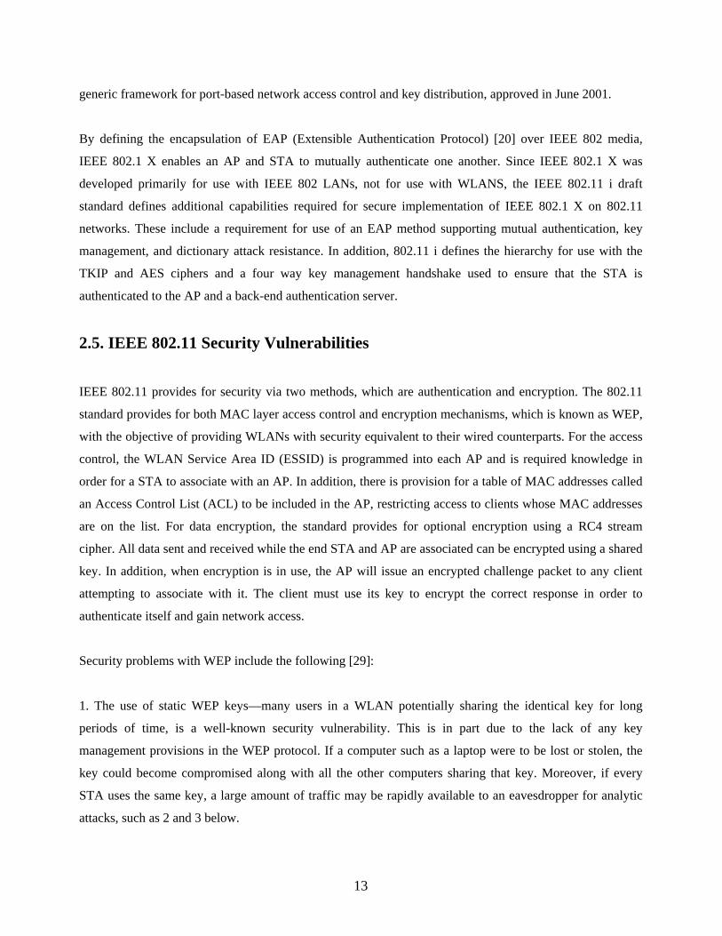
(Refer Figure 5)
Figure 5: VPN Assault
The attacker then acts as the AP in presenting a challenge to the authorized STA. The STA computes the
appropriate response, which is sent to the AP. The AP then sends the STA a success packet with an
imbedded sequence number. Both are captured by the attacker. After capturing all this data, the attacker
then has what he needs to complete the attack and defeat the VPN. The attacker sends a spoofed reply with
large sequence number, which bumps the victim’s station off the network and keeps it from re-associating.
The attacker then enters the network as the authorized station.
2.6.5. Power Saving Vulnerabilities [8]
The Power Save mode in 802.11 allows STAs to enter into a sleep state during which they are unable to
transmit or receive. Before entering the sleep state the STA sends its intention to the AP so that the AP can
start buffering any inbound traffic. Periodically the STA polls the AP for any pending traffic. If there is any
buffered data at this time, the AP delivers it and subsequently discards the contents of its buffer. By
spoofing the polling message on behalf of the STA, an attacker may cause the AP to discard the STA’s
packets while it is asleep. It is also potentially possible to trick the STA node into thinking there are no
buffered packets at the AP when in fact there are. The presence of buffered packets is indicated in a
periodically broadcast packet called the Traffic Indication Map (TIM). If the TIM message itself is spoofed,
an attacker may convince a STA that there is no pending data for it and the STA will immediately revert
back to the sleep state. The power saving mechanism relies on time synchronization between the AP and its
STAs so the STAs know when to awake. Key synchronization information, such as the period of TIM
packets and a timestamp broadcast by the AP, are sent unauthenticated and in the clear. By forging these
management packets, an attacker can cause a STA node to fall out of sync with the AP and fail to wake up
20

at the appropriate times.
2.6.6. Virtual Carrier Sense Attack [8]
The virtual carrier sense mechanism is used to mitigate collisions. Each 802.11 frame carries a duration
field that indicates the number of microseconds that the channel is reserved. The duration field is used to
program the Network Allocation Vector (NAV) on each node. Only when a node’s NAV is zero is it
allowed to transmit. This feature is used by RTS and CTS handshake that can be used to synchronize.
During the handshake the sending node sends a small RTS frame that includes the duration large enough to
complete the RTS/CTS sequence, including the STS frame, the data frame and ACK frame. An attacker
may assert a large duration field value preventing other STAs access to the channel. The maximum value of
the NAV is 32767, approximately 32 milliseconds, so an attacker need only transmit 30 times in a second to
jam all access to the channel.
2.6.7. PLME_DSSSTESTMODE (Jamming) Attack [13]
This is a PHY layer attack. It exploits a test mode in the IEEE 802.11b DSSS specification. It takes
advantage of a test mode (PLME_DSSSTESTMODE) of operation present in 802.11b WLAN adapters
(PCMCIA Cards/ APs) to continuously transmit a DSSS signal on a target channel. This continuous
transmission effects all stations within range of the attacker (whether STAs or APs) using the target
channel, resulting in the CSMA/CA reporting the media as busy for the duration of the attack.
The impact of this is that no station within range of the attacker will be able to seize the media for
transmission, resulting in DoS of the target channel.
The flaws in 802.11’s basic security mechanisms and vulnerabilities of 802.11 to the various above
mentioned attacks have initiated the IEEE to propose 802.1 X as one of the initiatives to further secure
802.11 WLANs.
21
Chapter 3. BACKGROUND OF IEEE 802.1 X
3.1. What is IEEE 802.1 X?
Researchers have demonstrated basic flaws in 802.11 encryption mechanism and authentication protocols,
which has led IEEE to create a series of protocol extensions and replacements. The IEEE 802.1 X standard
defines a port-based network access control. It can be based on Extensible Authentication Protocol (EAP)
[2], which provides a wide variety of authentication mechanisms. The access control is performed at the
MAC level (it is PHY independent). 802.1 X provides network access control through the concept of a port.
A port is any kind of controlled access, for example a router, switch or modem line for dial-up. 802.1 X was
not initially designed for WLANs. The IEEE defines a virtual port as an association between a STA and an
AP. To associate with an AP, the STA has to authenticate first (802.11 authentication). Once associated
with a specific AP, the STA can go through 802.1 X authentication. 802.1 X provides per-station, per-
session keys, and causes these keys to be changed often, solving reuse issues.
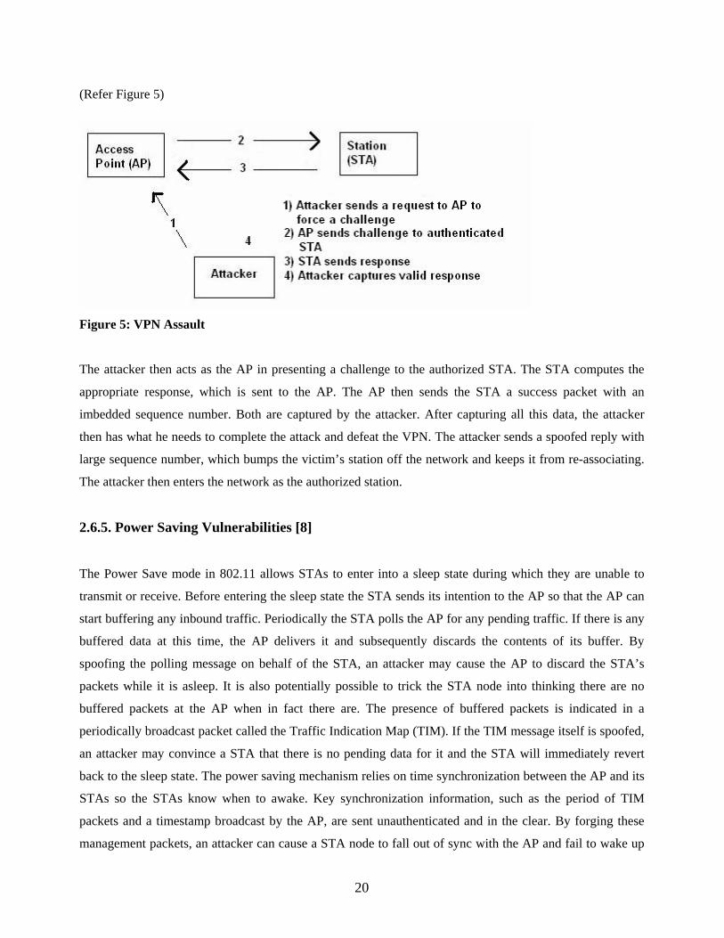
The 802.1 X framework provides the link layer with extensible authentication, normally seen in higher
layers (Refer Figure 6).
Figure 6: 802.1 X Layers
802.1 X requires two entities:
• The supplicant, which resides on the wireless STA
• The authenticator, which resides on the AP
22

The authentication server (optional) resides on the RADIUS (discussed in Section 3.2) server.
These entities are logical entities on the network devices. The authenticator creates a logical port per client,
based on the client's Association ID (AID). This logical port has two data paths. The uncontrolled data path
allows network traffic through to the network. The controlled data path requires successful authentication to
allow network traffic through (Refer Figure 7).
Figure 7: 802.1 X Ports
The supplicant becomes active on the medium and associates to the AP. The authenticator detects the client
association and enables the supplicant's port. It forces the port into an unauthorized state so that only 802.1
X traffic is forwarded. All other traffic is blocked. The client may send an EAP Start message, although
client initiation is not required (Refer Figure 8).
The authenticator replies with an EAP Request Identity message back to the supplicant to obtain the client's
identity. The supplicant's EAP Response packet containing the client's identity is forwarded to the
authentication server.
The authentication server is configured to authenticate clients with a specific authentication algorithm.
Currently, 802.1 X for 802.11 LANs does not stipulate a specific algorithm to use thus allowing a variety of
authentication algorithms to operate over it.
The end result is a RADIUS -ACCEPT or RADIUS-REJECT packet from the RADIUS server to the AP.
Upon receiving the RADIUS ACCEPT packet, the authenticator transitions the client's port to an authorized
state, and traffic may be forwarded.
23

Figure 8: 802.1 X and EAP Message Flow
IEEE 802.1 X can be implemented entirely on the AP (by providing support for one or more EAP methods
within the AP), or it can utilize a backend authentication server. The IEEE 802.1 X standard supports
authentication protocols such as RADIUS, Diameter, and Kerberos. RADIUS [21] enables authentication,
authorization, and accounting for Network Access Server (NAS) devices, including dial-up, xDSL, and
802.11. The 802.1 X standard can be implemented with different EAP types, including EAP-MD5 [20]
(supports only one-way authentication without key exchange) for Ethernet LANs and EAP-TLS [22]
(supports fast reconnect, mutual authentication and key management via certificate authentication).
Currently new generations of EAP methods are being developed within the IETF, focused on addressing
wireless authentication and key management issues. These methods support additional security features
such as cryptographic protection of the EAP conversation, identity protection, secure ciphersuite
negotiation, tunneling of other EAP methods, etc.
The use of EAP and RADIUS along with 802.1 X provides a user-based identification, a choice of
authentication methods and a centralized user management as well as a dynamic key management. EAP and
RADIUS are described in more detail later in this chapter.
24
3.2. RADIUS
RADIUS (Remote Authentication Dial-In User Service) [21] has been widely used by business and Internet
Service Providers (ISPs) to control remote access.
A RADIUS client is a type of network access server (NAS), in our case this is an AP, and sends
authentication and accounting requests to the RADIUS server (authentication server) in order to gain
network access. Communications between the RADIUS server and the RADIUS client are authenticated
through a shared secret. Each AP has its own shared secret with the RADIUS server. In general the
transport protocol used is UDP and the RADIUS server listens on the port.
RADIUS supports a variety of authentication protocols like Challenge Handshake Authentication Protocol
(CHAP), Microsoft Challenge Handshake Authentication Protocol (MS-CHAP) and EAP. The main
advantage of EAP is that it supports different methods of authentication. The choice of EAP method is
negotiated by the client and RADIUS server during the authentication phase.
3.3. EAP
EAP (Extensible Authentication Protocol) [20] is essentially a transport protocol. Its main advantage is that
it provides an authentication framework and can be used by a variety of different authentication types
known as EAP methods. It is supposed to head off proprietary authentication systems. It is designed to
allow authentication methods to be deployed with no changes to the AP. EAP is used to pass the
authentication information between the supplicant and the authentication server. The choice of
authentication type is defined by the EAP type. The software supporting the EAP type resides on the
authentication server and within the operating system of the client. The AP can be seen as a bridge between
the supplicant and the authentication server. One of the goals of EAP is to enable development of new
authentication methods without modifying the AP. One of the key points of 802.1 X is that the authenticator
can be simple and dumb, all of the brains have to be in the supplicant and the authentication server. This
makes 802.1 X ideal for wireless APs, which typically have little memory and processing power. Since the
authentication mechanism is independent of the AP, we can specify any EAP methods without updating
APs.
25

3.3.1. Overview of EAP Packets
EAP exchanges are composed of requests and responses. The authenticator (AP) sends requests to the
supplicant (wireless STA that wants to access the network). The supplicant responds. Based on the
credentials of the supplicant, the access will be granted or denied. There are two kinds of EAP packets
(Refer Figure 9):
• EAP request and response
• EAP success and failure
The Data Type carried by the EAP request and response packets can be:
Data-type 1: The ID of the supplicant
Data-type 2: Notification: used to provide messages to the user
Data-type 3: NAK: used to suggest another authentication method
Data-type: 4-13 Kind of authentication type (EAP-MD5, EAP-TLS, EAP-TTLS, EAP-PEAP, LEAP etc...).
At the end of the EAP exchange, the authenticator grants access or not to the network. The EAP success and
failure packets do not contain data. It only specifies if the user has been authenticated or not following the
requests and responses. The Data Type carried by the EAP success and failure packets are either Data Type
3 in case of a success and Data Type 4 in case of a failure.
NAK is used to suggest another authentication method. That is the client and RADIUS server negotiate the
choice of authentication during the authentication phase. Figure 10 shows a typical EAP exchange.
26

Figure 9: Kind of EAP Packets
27
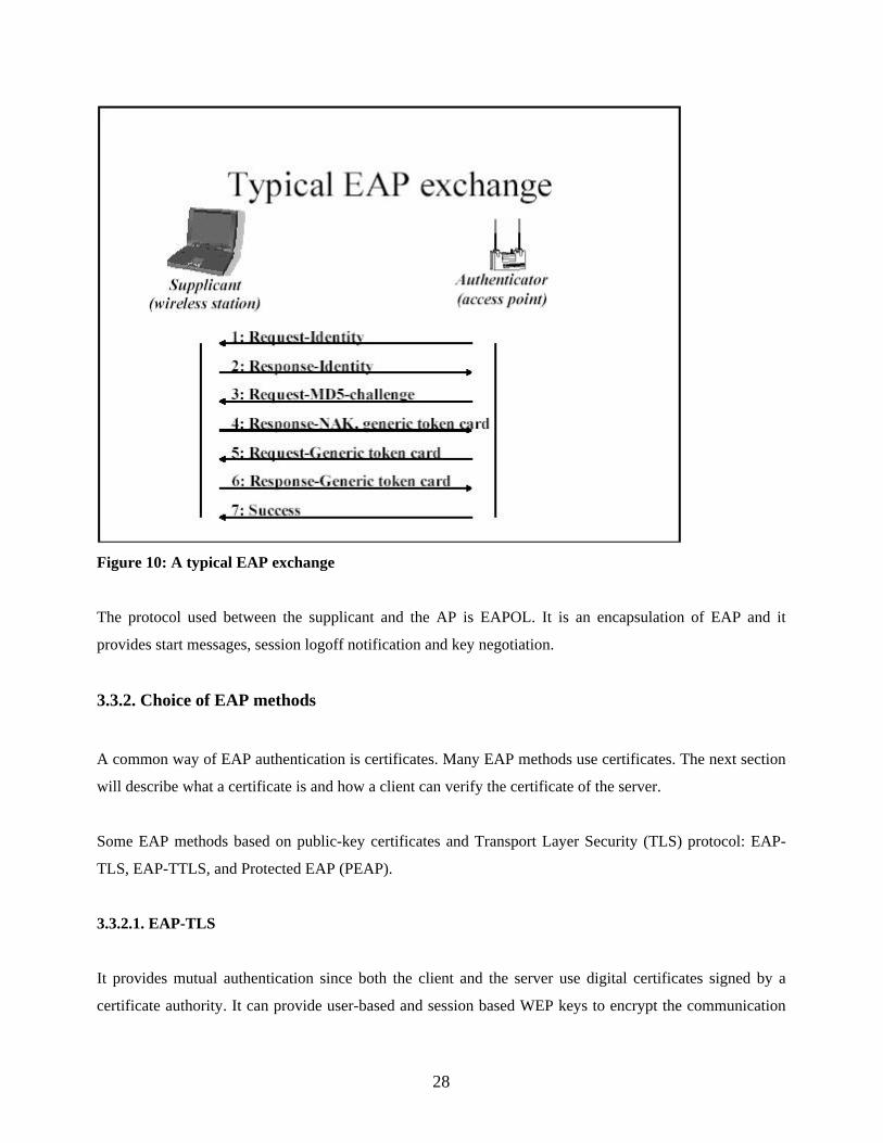
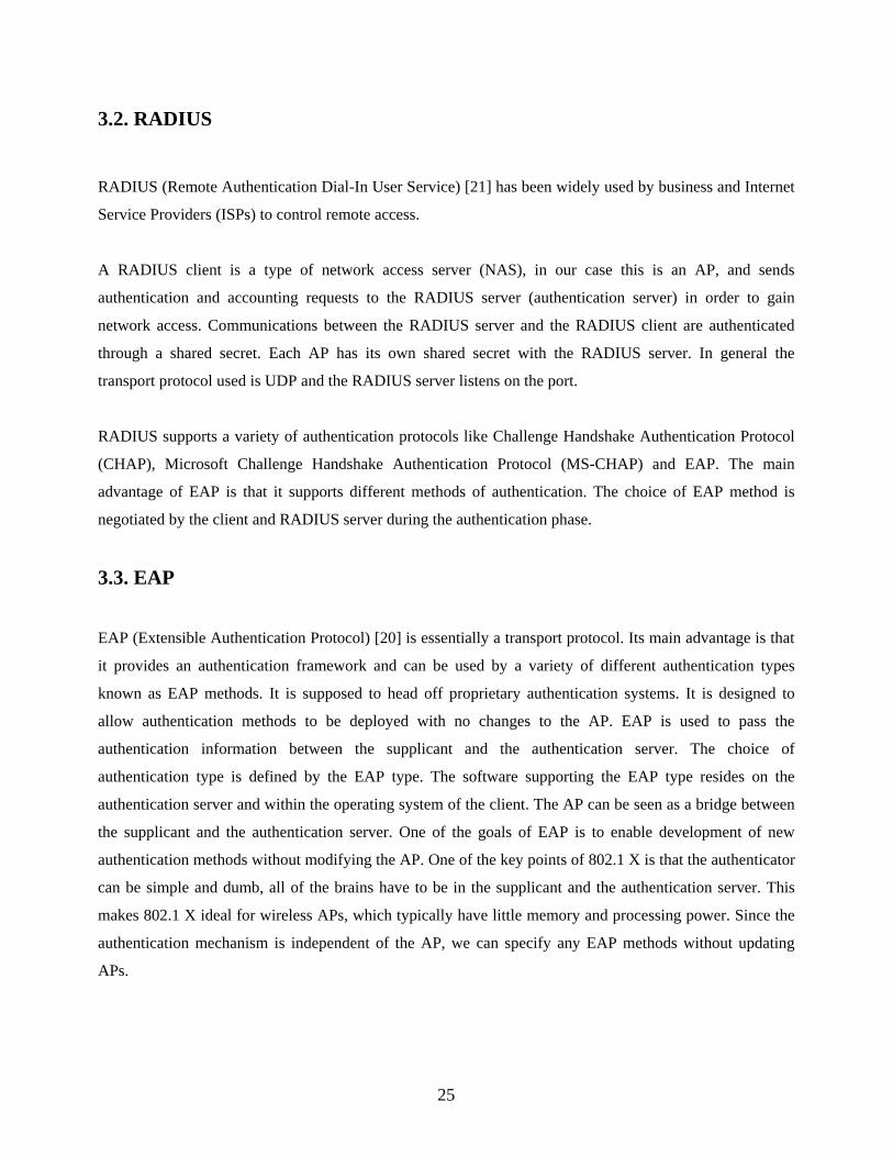
Figure 10: A typical EAP exchange
The protocol used between the supplicant and the AP is EAPOL. It is an encapsulation of EAP and it
provides start messages, session logoff notification and key negotiation.
3.3.2. Choice of EAP methods
A common way of EAP authentication is certificates. Many EAP methods use certificates. The next section
will describe what a certificate is and how a client can verify the certificate of the server.
Some EAP methods based on public-key certificates and Transport Layer Security (TLS) protocol: EAP-
TLS, EAP-TTLS, and Protected EAP (PEAP).
3.3.2.1. EAP-TLS
It provides mutual authentication since both the client and the server use digital certificates signed by a
certificate authority. It can provide user-based and session based WEP keys to encrypt the communication
28

channel between the client and the AP. This is a very secure authentication method. The certificates can be
replaced by smart cards thus authenticating the user instead of the device. However, it requires all the user
devices to have certificates. So, the cost of administration is high.
EAP-TLS is based on SSL v3.0. TLS is designed to provide secure authentication and encryption for a
TCP/IP connection. To provide this functionality, TLS comprises three protocols:
• Handshake protocol: The handshake protocol negotiates the parameters for the SSL session. The
SSL client and server negotiate the protocol version, encryption algorithms, authenticate each
another, and derive encryption keys.
• Record protocol: The record protocol facilitates encrypted exchanges between the SSL client and
the server. The negotiated encryption scheme and encryption keys are used to provide a secure
tunnel for application data between the SSL endpoints.
• Alert protocol: The alert protocol is the mechanism used to notify the SSL client or server of errors
as well as session termination.
TLS authentication is generally split into two methods: server-side authentication and client-side
authentication. Server-side authentication uses public key infrastructure (PKI), namely PKI certificates.
Client-side authentication can also use PKI certificates, but this is optional. EAP-TLS uses client-side
certificates.
3.3.2.2. PKI and Digital Certificates
PKI encryption is based on asymmetric encryption keys. A PKI user has two keys: a public key and a
private key. Any data encrypted with the public key can be decrypted only with the private key, and vice
versa. For example: Mr. X gives Ms. Y his public key. Ms. Y then sends Mr. X an e-mail encrypted with his
public key. For Mr. X to read the message, he has to decrypt the message with his private key. Because Mr.
X is the only person with access to his private key, only he can decrypt the message (Refer Figure 11).
29

Figure 11: Public Key Encryption
Digital certificates are data structures distributed by a certificate authority that join a public key to a user. A
digital certificate is generally made up of the following pieces of information:
• Certificate version
• Serial number
• Certificate issuer
• User
• User's public key
• Validity period
• Optional extensions
• Signature algorithm
• Signature
The digital signature is derived by combining the certificate version, serial number, issuer, user, user's
public key, and validity period and running the values through a keyed hash function. The certificate
authority keys the hash with its own private key (Refer Figure 12).
Figure 12: Digital Signature
30

3.3.2.3. TLS Authentication Process
The TLS process begins with the handshake process:
1. The SSL client connects to a server and makes an authentication request
2. The server sends its digital certificate to the client
3. The client verifies the certificate's validity and digital signature
4. The server requests client-side authentication
5. The client sends its digital certificate to the server
6. The server verifies the certificate's validity and digital signature
7. The encryption and message integrity schemes are negotiated
8. Application data is sent over the encrypted tunnel via the record protocol
3.3.2.4. EAP-TLS Authentication Process
The EAP-TLS authentication process is as follows (Refer Figure 13):
1. The client sends an EAP Start message to the AP
2. The AP replies with an EAP Request Identity message
3. The client sends its Network Access Identifier (NAI), which is its username, to the AP in an EAP
Response message
4. The AP forwards the NAI to the RADIUS server encapsulated in a RADIUS Access Request message
5. The RADIUS server will respond to the client with its digital certificate
6. The client will validate the RADIUS server's digital certificate
7. The client will reply to the RADIUS server with its digital certificate
8. The RADIUS server will validate the client's credentials against the client digital certificate
9. The client and RADIUS server derive encryption keys
31

10. The RADIUS server sends the AP a RADIUS ACCEPT message, including the client's WEP key,
indicating successful authentication
11. The AP sends the client an EAP Success message
12. The AP sends the broadcast key and key length to the client, encrypted with the client's WEP key.
Figure 13: EAP-TLS Authentication Process [9]
3.3.2.5. EAP-TTLS / PEAP [9]
It is a hybrid method combining EAP-TLS and a traditional password-based method or another legacy
method. This is to remove the burden of managing user certificates. Only the server needs a certificate. Like
with EAP-TLS, encryption keys are generated during the authentication exchange.
For client-side authentication, Protected EAP (PEAP) can use any other EAP authentication type. Because
PEAP establishes a secure tunnel via server-side authentication, non-mutually authenticating EAP types can
be used for client-side authentication, such as EAP generic token card (GTC) for one-time passwords
(OTP), and EAP MD5 for password based authentication.
32
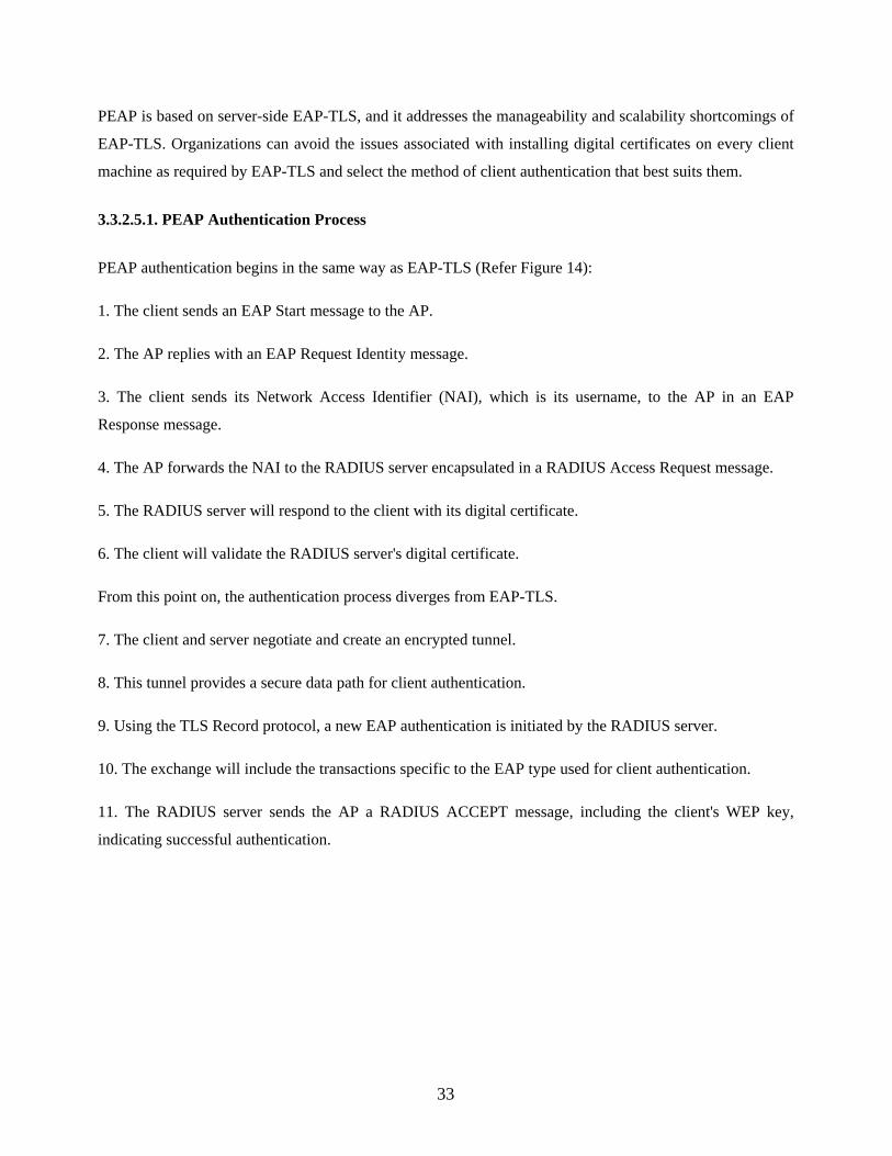
PEAP is based on server-side EAP-TLS, and it addresses the manageability and scalability shortcomings of
EAP-TLS. Organizations can avoid the issues associated with installing digital certificates on every client
machine as required by EAP-TLS and select the method of client authentication that best suits them.
3.3.2.5.1. PEAP Authentication Process
PEAP authentication begins in the same way as EAP-TLS (Refer Figure 14):
1. The client sends an EAP Start message to the AP.
2. The AP replies with an EAP Request Identity message.
3. The client sends its Network Access Identifier (NAI), which is its username, to the AP in an EAP
Response message.
4. The AP forwards the NAI to the RADIUS server encapsulated in a RADIUS Access Request message.
5. The RADIUS server will respond to the client with its digital certificate.
6. The client will validate the RADIUS server's digital certificate.
From this point on, the authentication process diverges from EAP-TLS.
7. The client and server negotiate and create an encrypted tunnel.
8. This tunnel provides a secure data path for client authentication.
9. Using the TLS Record protocol, a new EAP authentication is initiated by the RADIUS server.
10. The exchange will include the transactions specific to the EAP type used for client authentication.
11. The RADIUS server sends the AP a RADIUS ACCEPT message, including the client's WEP key,
indicating successful authentication.
33

Figure 14: PEAP Authentication Process [9]
3.4. 802.1 X over 802.11
In this section, I show how 802.1 X can integrate with 802.11. (Refer Figure 15).
1) The STA must first associate with an AP. In 802.11, the association follows the authentication (Open-
system or Shared-key). Once the association is made, the communication between the STA and the AP can
start. The authentication server uses specific authentication techniques, to verify client’s identity
(Passwords, digital certificates).
2.a) The supplicant can trigger the authentication process by sending an EAPOL start message. The
authenticator allows only EAP traffic and blocks all other traffic, such as HTTP, DHCP, and POP3 packets.
2.b) The authenticator sends an EAP-Request/Identity packet to the supplicant once it has associated with
the AP.
3) The supplicant sends an EAP-Response/Identity packet to the authenticator to prove its identity. The
34

packet is then routed to the authentication server encapsulated in RADIUS protocol (an EAP-Message
attribute is used to encapsulate EAP packets for transmission from the authenticator to the RADIUS server).
4) The authentication server sends back a challenge to the authenticator. The challenge depends on the EAP
method chosen. The authenticator unpacks this from RADIUS and re-packs it into EAPOL and sends it to
the supplicant. At this point, the number of exchanged messages will vary according to the EAP method.
Only mutual authentication is considered appropriate for WLANs.
5) The supplicant replies to the challenge via the authenticator, which routes the response to the back-end
server.
6) If the supplicant provides appropriate credentials, the authentication server responds with a success
message -Access Accept-, which is then forwarded to the supplicant. The authenticator now unblocks the
controlled port and allows normal traffic. However, RADIUS allows a per-user configuration. Certain users
may have restricted access. In this case, the restrictions are specified in the RADIUS message Access-
accept sent to the AP. For example, the authenticator might switch the supplicant to a particular VLAN or
install a set of firewall rules. EAP supports dynamic keying. That happens when the authentication
succeeds.
7) EAPOW-key is used to transport the global keys.
8) An EAPOL logoff notification can be sent to the authenticator to announce the end of the connection.
802.1 X also defines a re-authentication timer, which can be used to periodically require the Supplicant to
re-authenticate.
35
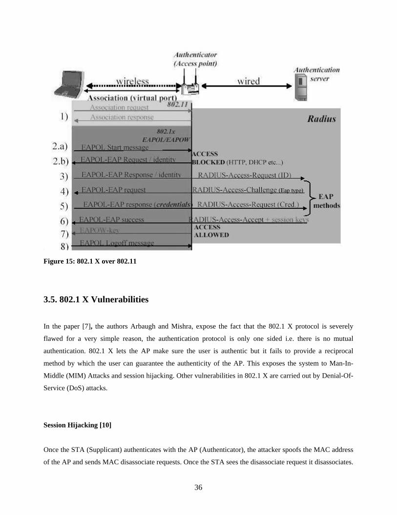
Figure 15: 802.1 X over 802.11
3.5. 802.1 X Vulnerabilities
In the paper [7], the authors Arbaugh and Mishra, expose the fact that the 802.1 X protocol is severely
flawed for a very simple reason, the authentication protocol is only one sided i.e. there is no mutual
authentication. 802.1 X lets the AP make sure the user is authentic but it fails to provide a reciprocal
method by which the user can guarantee the authenticity of the AP. This exposes the system to Man-In-
Middle (MIM) Attacks and session hijacking. Other vulnerabilities in 802.1 X are carried out by Denial-Of-
Service (DoS) attacks.
Session Hijacking [10]
Once the STA (Supplicant) authenticates with the AP (Authenticator), the attacker spoofs the MAC address
of the AP and sends MAC disassociate requests. Once the STA sees the disassociate request it disassociates.
36

The RSN state machine (Refer Figure 16) goes to UNASSOCIATE and 802.1 X is still in
AUTHENTICATED state.
Figure 16: RSN State Machine
The attacker then gains access to the network spoofing the MAC address of the STA, 802.1 X state machine
for AP is still in authenticated state. (Refer Figure 17).
37

Figure 17: Session Hijack Flow [10]
Denial Of Service attacks [10]
DoS attacks can be performed in many ways. One way a DoS attack is performed is by 802.11 Management
frame spoofing. Since the AP sends de-authenticate messages, the STA gets logged off. 802.11
management messages include beacon, probe request/response, association request/response, reassociation
request/response, disassociation, and deauthentication. Without authenticating these management messages,
denial of service attacks are possible.
Another DoS attack is to send a flood of associate requests [8]. After the 802.11 association phase and
during 802.1 X authentication phase, the AP can hold only a set limit of state information and if a lot of
requests are flooded, the AP can not accept these requests.
Lucent, Cisco, Funk Software have come up with separate replies for 802.1 X vulnerabilities. Their
solutions perform mutual authentication between STA and AP. The dynamic keys are created locally on the
client and server.
38

Cisco’s LEAP, which is also called Light EAP uses dynamic WEP keys, mutual authentication and the AP
rejects packets that are not encrypted.
Lucent’s CHAP performs client authentication with AP and there is a TLS tunnel between client and server.
The client authenticates a digital certificate from the server, then the client sends a hashed password, name
and challenge.
Kerberos and LEAP are vulnerable to dictionary attacks [15] and there are lots of LEAP cracking tools
available like ASLEAP , THC LEAP and ANWRAP LEAP.
Most of the problems in 802.1 X seem to be addressed with 802.11 i but there will still be a need for change
of hardware and firmware. IEEE 802.11 i does not have any defense mechanisms for some of the Denial-of-
Service attacks like PLME_DSSSTESTMODE (Jamming) attack since it protects MAC layer Protocol Data
Units (PDUs) and PLME_DSSSTESMODE attack operates at the Physical Layer Convergence Protocol
(PLCP) layer. Hence there is still a need for security on 802.11, 802.1 X or 802.11 i network based systems.
Any unprotected 802.11, 802.1 X or 802.11 i network is vulnerable to many attacks and WIDS can provide
an external layer of security to protect these networks.
39

Chapter 4. INTRUSION DETECTION
Intrusion detection is a process that detects rogue users attempting to access, have already accessed, or have
compromised the WLAN. Intrusion Detection System (IDS) for WLANs can be host-based, network-based,
or hybrid, the hybrid combining features of host- and network-based IDS [27].
A host-based IDS includes a host-based program, which is installed on a system and monitors it for
suspicious behavior. The agent could halt an attack on a system but its primary function is to log and
analyze events and send alerts.
A network-based IDS monitors network traffic (each packet) in real time and determines whether traffic
conforms to predetermined attack signatures (activities that match known attack patterns). For example, a
DoS attack sends packets that are fragmented in such a way as to crash the target system. The network
monitor will recognize packets that conform to this pattern and take action such as killing the network
session, sending an e-mail alert to the administrator, or other action specified.
Host-based IDS has an advantage over network-based IDS when encrypted connections such as SSL Web
sessions or VPN connections are involved, since the agent resides on the component itself, the host-based
system is able to examine the data after it has been decrypted. In contrast, a network-based IDS is not able
to decrypt data therefore, encrypted network traffic is passed through without investigation.
IDS on wired networks cannot be directly applied to WLANs. A Network-based IDS component on a wired
network behind the AP will not detect attacks directed from one STA to another STA (peer to peer) on the
same subnet. The wireless AP switches traffic directly between STAs. The traffic does not enter the wired
network, it is WEP encrypted, and the IDS component does not have an opportunity to capture clear-text
packets for analysis. IDS components on the wired network usually will not detect attempts to de-associate
a legitimate STA from the WLAN and will not detect the association of an unauthorized STA with the
WLAN.
Flooding, jamming, and other DOS attacks against wireless devices use physical and data-link layer
techniques that are not visible to the IDS components at a packet level. IDS on wired networks will not
identify the physical location of rogue APs within the building. These rogue APs can act as entry points for
unauthorized wireless access from remote locations.
40

IDS components will not detect an authorized STA communicating peer-to-peer with an unauthorized STA.
This scenario can create a bridge into the wired network by allowing a rogue user to connect to a STA that
is operating in “ad hoc” mode. The ad hoc mode allows a STA to be used to relay traffic to the network and
creates a number of potential attack scenarios.
There is a need to architect a wireless IDS, that is capable to handle all the shortcomings of a wired IDS.
Hence a wireless IDS should be capable of detecting unauthorized peer-to-peer communications within the
WLAN. It should be able to track and physically locate the unauthorized APs/STAs, analyze wireless traffic
and monitor 802.11 RF space and generate an alarm upon detection of unauthorized configuration changes
to wireless devices that violate security policy, detect flooding and de-association attempts before they
successfully compromise the WLAN and provide centralized monitoring and management features.
WIDS is an intrusion detection system that is capable of providing perimeter security to an internal WLAN.
WIDS is capable of detecting, tracking and locating intruders using directional antenna. WIDS also has the
capability to sniff passively in RF Monitor mode and analyze wireless traffic and detect outside perimeter
rogue APs.
41

Chapter 5. TRACKING AND LOCATION
While detection of rogue APs and unauthorized ad-hoc networks is certainly useful, physically tracking the
offender is more interesting.
Most triangulation today uses directional techniques. A dish or other directional antenna with a narrow
range is attached to a receiver and then an area is scanned for the strongest signal. The STA is moved some
distance away, the area is scanned again, and then the position is found using simple trigonometry. (Refer
Figure 18)
Figure 18: Tracking by triangulation.
In practice, there is usually more involved than this. Terrain, obstructions, heat and atmospheric effects,
reflections, refraction, antenna design, and many other factors that could affect the apparent location of the
transmitter affect radio propagation. The apparent location of the strongest signal may not actually be the
location of the transmitter. A full discussion of these effects is beyond the scope of this paper.
Regardless, the basic theory is sound and can be a very effective technique to locate a transmitter. Another
technique, not quite as common today, is to locate the transmitter using only the relative signal strength at
various well-placed locations around the area, and if known, the free-space propagation losses and the
power of the transmitter.
If we know the output power of the transmitter, the gain of the receiving and transmitting antennas, power
drop-off, and the received signal strength, location of transmitter to two possible locations should be
42

possible with only two samples.
At point A, from the signal strength and power drop-off equation, we would be able to determine the
distance from the transmitter (Refer Figure 19). At point B, we would also know that, so the location of the
transmitter will be found at the point(s) where both dA and dB meet:
Figure 19: Tracking by signal strength.
If we do not know the strength of the transmitter or the gain of any of the antennas involved, we just have to
introduce one more unknown, a signal strength ratio, so the problem turns into a simultaneous equation with
three unknowns. Thus, a minimum of three data points is needed. If these data points are well placed, there
should only be one or two realistic solutions to the equations.
A paper by Frank Adelstein, Prasanth Alla, Rob Joyce and Golden G. Richard III [23] related to WIDS
documents attempts to locate an intruding wireless station. In this paper the authors locate an intruder’s
position by rotating a directional antenna 360 degree’s while monitoring signal strength. An antenna’s
signature is computed ahead of time and the intruder’s location is computed by comparing the intruder’s
data to the signature data.
Experiments were done with three different types of directional antennas. The test antenna was mounted
on a telescope tripod and connected to a portable AP consisting of a laptop running Linux and HostAP
[17]. The antenna’s signature was computed by placing an intruder machine a few hundred feet away from
the AP. The intruder associated with the AP and the directional antenna was rotated in fixed increments and
the signal strength value was recorded. Readings were taken over a 360 degree range.
43

In order to compute the location of an intruder, several readings of the intruder’s signal strength data were
made at different angles of the AP antenna. The intruder’s data was correlated with the signature data and
the computed angle is the angle with the best fit to the known signature data. Two different locations of
the AP were used. The results of the tests computed the location of the intruder within 2 to 4 degrees.
The intruder’s location was computed using triangulation with the computed angles and access point
locations.
The research showed that it is possible to determine the intruder’s location with reasonable accuracy using
low priced off the shelf hardware and free software. A Wireless Intrusion Detection System (WIDS) could be
implemented through the knowledge gained from the research to locate intruder’s and also provide an external
layer of security to a WLAN.
44
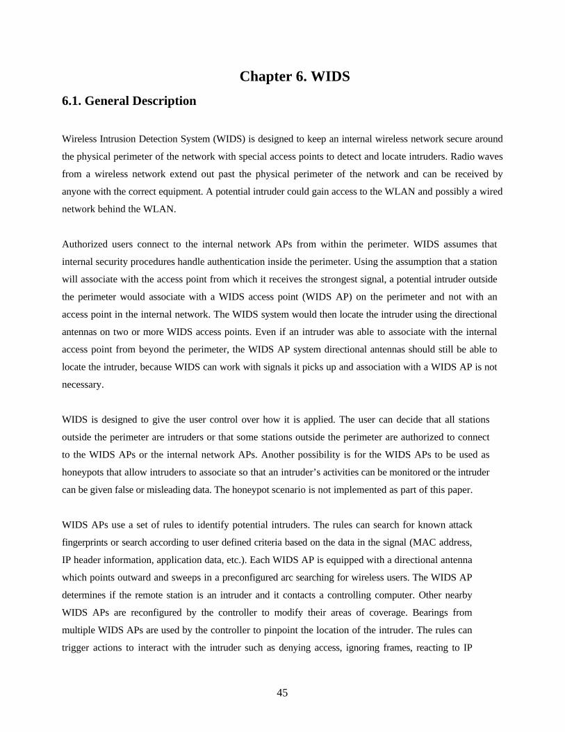
Chapter 6. WIDS 6.1. General Description
Wireless Intrusion Detection System (WIDS) is designed to keep an internal wireless network secure around
the physical perimeter of the network with special access points to detect and locate intruders. Radio waves
from a wireless network extend out past the physical perimeter of the network and can be received by
anyone with the correct equipment. A potential intruder could gain access to the WLAN and possibly a wired
network behind the WLAN.
Authorized users connect to the internal network APs from within the perimeter. WIDS assumes that
internal security procedures handle authentication inside the perimeter. Using the assumption that a station
will associate with the access point from which it receives the strongest signal, a potential intruder outside
the perimeter would associate with a WIDS access point (WIDS AP) on the perimeter and not with an
access point in the internal network. The WIDS system would then locate the intruder using the directional
antennas on two or more WIDS access points. Even if an intruder was able to associate with the internal
access point from beyond the perimeter, the WIDS AP system directional antennas should still be able to
locate the intruder, because WIDS can work with signals it picks up and association with a WIDS AP is not
necessary.
WIDS is designed to give the user control over how it is applied. The user can decide that all stations
outside the perimeter are intruders or that some stations outside the perimeter are authorized to connect
to the WIDS APs or the internal network APs. Another possibility is for the WIDS APs to be used as
honeypots that allow intruders to associate so that an intruder’s activities can be monitored or the intruder
can be given false or misleading data. The honeypot scenario is not implemented as part of this paper.
WIDS APs use a set of rules to identify potential intruders. The rules can search for known attack
fingerprints or search according to user defined criteria based on the data in the signal (MAC address,
IP header information, application data, etc.). Each WIDS AP is equipped with a directional antenna
which points outward and sweeps in a preconfigured arc searching for wireless users. The WIDS AP
determines if the remote station is an intruder and it contacts a controlling computer. Other nearby
WIDS APs are reconfigured by the controller to modify their areas of coverage. Bearings from
multiple WIDS APs are used by the controller to pinpoint the location of the intruder. The rules can
trigger actions to interact with the intruder such as denying access, ignoring frames, reacting to IP
45

header data, etc.
6.2. WIDS Architecture and Design
WIDS is an intrusion detection system that is classified as a network based IDS [27]. The WIDS
architecture consists of one or more WIDS access points connected to a centralized controller via a standard
wired network. The wired network provides a more secure management of the WIDS AP’s than a wireless
network.
WIDS APs use an open-source access point code, HostAP [17] and Linux. HostAP allows an 802.11b
wireless Prism 2/2.5 Ethernet card to be used as an access point instead of a remote station. HostAP has
been extended to include the additional functions needed by WIDS. The controller is a personal computer
running Linux. The controller software is written in Perl using Perl-TK to construct the graphical interface.
We investigated several designs and configurations for the WIDS AP hardware and decided that it should be
an embedded computer equipped with a rotating directional antenna. The WIDS AP would be built from
components including an X-Scale single board computer and wireless networking platform, a directional
antenna, a stepper motor to rotate the antenna, and a stepper motor controller. A list of the components is
presented in the Appendix of this paper. Unfortunately, we were not able to obtain financing to build a fully
functional WIDS AP equipped with the rotating antenna. A laptop computer without a rotating directional
antenna was used in our implementation and directional antenna components were simulated in the software,
for example the antenna readings file was generated by hand.
Since some 802.11 frames that are handled by the Prism 2/2.5’s firmware when in hostAP can only be
captured by a wireless card in monitor mode, a configuration with two Prism 2/2.5 cards, one in hostAP
mode and one in monitor mode provides WIDS with more intrusion detection capabilities. The card in the
monitor mode can capture data, control, and the management frames that are handled by the card’s
firmware and pass them to the modified HostAP software for processing and testing. The card in the
monitor mode can also receive the HFA384x (refer section 6.7) transaction frames that show time, signal,
silence and rate.
46
WIDS access point Internal access point Station (possible intruder) Orientation of a WIDS AP attached directional antenna Estimates of an intruder’s location External/Rogue access point
Figure 20: WIDS Architecture Figure 20 depicts four WIDS access points, arranged vertically on the left, protecting an internal wireless
network installed in an arena. Only one side of a WIDS installation is shown in order to keep the picture
simple. (A complete WIDS installation would include WIDS AP’s on all four sides of the arena.) The WIDS
access points connect to a controller computer via a wired network. The controller can be located inside the
perimeter. The arena contains six internal access points. The signals transmitted by the internal AP’s extend
outside of the perimeter of the arena. The arrows originating from each WIDS access point show the current
orientation of an attached directional antenna. The other dotted lines extending from two of the WIDS
access points represent station signals picked up by the directional antennas. The triangulation lines
47
represent bearings on the station and a square indicates the location of a station. The outer dotted circles are
external APs detected by WIDS. Hence, WIDS is designed to strengthen the security of an internal
wireless network by surrounding physical perimeter of the network with special access points to detect
and locate intruder signals from a wireless network extended out past the physical perimeter of the
network received by anyone with the correct equipment.
6.3. Typical WIDS Installation with 802.1 X
A typical WIDS installation (Refer Figure 21) consists of a normal omni-directional AP located in the
center of the physical facility and WIDS APs located around the perimeter and directional antennas pointing
outward. (Note that there could be multiple omni, or directional, APs inside the perimeter, I do not show
them in the figure to keep the explanation at the basic level.) The WIDS APs sweep their directional
antennae in preconfigured arcs, searching for wireless users. Authorized users connect to the omni AP from
within the perimeter. I also assume that internal security procedures handle authentication inside the
perimeter. The problem is that the omni AP’s coverage extends beyond the physical perimeter. WIDS
addresses this problem because an intruder attempting to break into the WLAN from the outside will
contact the WIDS APs before coming within range of the omni AP. The WIDS APs will detect intrusions
based on both known attack signatures (such as network probes from NetStumbler [18] or other non-passive
“war-driving” programs [19]) and behavior based signatures (such as an internal MAC address suddenly
appearing in an external location on a machine with different OS characteristics than it had previously).
48

Figure 21: Typical WIDS installation with 802.1 X.
WIDS detects anomalous behavior by tying the signature data into a behavior-based intrusion detection
system [9, 10]. When a WIDS AP detects an unauthorized wireless user, the controller is contacted and
other nearby WIDS APs are reconfigured (by the controller) to modify their areas of coverage (i.e., the arc
that their directional antennae travel through are modified appropriately). Information from multiple WIDS
APs is used by the controller in order to pinpoint the physical location of unauthorized users.
6.4. WIDS Access Point/Controller Protocol The WIDS access points and the controller communicate over TCP, using the WIDS Access
Point/Controller Protocol (WCP). This section presents a summary of the communications between
access points and the controller. Access Point/Controller Protocol message types are printed in upper
case letters.
An access point starts up and attempts to connect to the controller using sockets. If the access point is
unable to connect, it retries every 5 seconds. When a connection is made, the access point sends a HELLO
message to the controller and waits for a response. The HELLO message contains the name of the access
49

point and its location. The controller replies with a CONFIG message containing the beginning and
ending sweep positions for the antenna, the report rate for sending data to the controller and the intrusion
detection rules to be used by the access point. The antenna begins sweeping and listening for signals. The
report rate specifies how often the access point sends REPORT messages to the controller. The REPORT
message contains the access point name, the position (angle) of the antenna, the sweep direction, the time,
the signal strength received at that position, and the MAC address of the station sending the signal.
When a signal is received which has the maximum signal strength in a specified number of readings, the access
point sends a POSITION message to the controller. The POSITION message contains the access point name,
the position of the antenna when the maximum signal strength was received, the MAC address of the station
sending the signal and whether or not the station is associated with the reporting access point.
The controller maintains a hash of POSITIONS received. The keys are the MAC addresses of the stations
and the values are strings containing the name of the access point that sent the POSITION message, an
integer indicating whether or not the access point and the station are associated, and another integer
indicating whether or not the station has been located.
When a POSITION message is received by the controller, the controller checks the hash for the MAC
address. If it is not found, the controller adds it to the hash, and checks if the station is associated with
the reporting access point. If it is associated, the controller determines which neighboring access point
needs to be reconfigured and sends a RECONFIG message with reconfigured antenna sweep information
to the applicable access point.
If the MAC address is in the hash, the controller checks the hash value to determine if the station has
already been located or if a POSITION message from the same access point with the same information has
been previously received. If so, the controller does nothing. If the MAC is in the hash with a different access
point and has not been located, the controller will use the information from both access points to compute
the station’s location. The hash is updated to show that this station has been located.
The controller will display a warning message if the same MAC address is associated with more than one
access point. This may be an indication that MAC address spoofing has occurred.
When an access point receives a RECONFIG message, it changes the starting sweep position or the ending
sweep position in accordance with the RECONFIG message. The antenna sweeps to the new position
50
twice and then returns to its original sweep configuration.
The controller operator can send messages to an access point to change the intrusion detection rules or to
collect statistics related to a station associated with the access point. A CHANGERULES message is sent
to change the intrusion detection rules. When the access point receives a CHANGERULES message, it
destroys its current rule tree and processes the new rules sent by the controller. A STATS message is sent to
gather statistics from an access point. The access point returns a STATS message containing a list of
stations associated with it in response to the controller’s STATS message. The controller operator selects a
station and sends a MAC message with the station’s MAC address. The access point reads the applicable
/proc/net/hostap/wlan0/MAC address file (it is a file that contains real time statistics like signal strength,
transmitted packets, bytes etc sent from the NIC firmware) and sends the stats information back to the
controller in a MACST message. The controller receives the MACST message, opens a new window and
displays the stats.
The access point can send a LOGDATA message to the controller. When the controller receives a
LOGDATA message, it writes the message to the controller’s log file.
6.5. WIDS Intrusion Detection Rules Each 802.11b frame received by a HostAP access point which is not handled by the wireless card’s
firmware can be tested with a set of intrusion detection rules. If the access point also has a wireless card
operating in the monitor mode, all 802.11b frames received can be tested with the rules. The results of the
rules tests are intended to identify potential intruders.
A rule has the format type-subtype, a test list consisting of one or more pairs of test and test data, and one
pair of action and action data. The type-subtype is the 802.11 frame type-subtype, the test is one of the
tests defined in the WIDS AP software, the test data is data used in the test, the action is one is one of the
actions defined in the WIDS AP software, and the action data gives more information about the action. The
action is performed only if all of the tests in the rule are true.
The type-subtype, test list, and action are separated by ‘,’. The test list is enclosed by ‘(‘ and
‘)’. The test keyword and test data are separated by a ‘:’. The end of a test keyword test data pair is
designated by an ‘!’. An action consists of an action keyword and action data pair. The action keyword
51

is separated from the action data by a ‘:’.
The test keyword generally describes an operation on a field in the 802.11 or the IP frame, such as
SOURCE_MAC_EQUALS for source MAC address equals, TTL_LESS_THAN for time to live is less
than, or FLAG_PWRMGMT for power management is on or off. The value to be tested is given by the
rule’s test data. Sample test data for test keywords are 00022D2E5C6a for SOURCE_MAC_EQUALS, 64
for TTL_LESS_THAN and OFF for FLAG_PWRMGMT.
An example of a rule is:
"MGMT_ASREQ, (SOURCE_MAC_EQUALS:00022D2E5C6a! FLAG_WEP:OFF!), LOG,
assoc request from 00:02:2D:2E:5D:6a flag wep off"
This rule is testing an association request. It is true if the source MAC address is 00:02:2D:2E:5C:6a and the
wep flag is 0. If the rule is true, the WIDS AP will send a message to the controller, which displays the
message in a terminal window and logs the message in a file. The message includes the WIDS AP name, date
and time of message, and the action data “assoc request from 00:02:2D:2E:5D:6a flag wep off.”.
6.6. Tools
WIDS is based on open-source access point, HostAP [17], using Prism 2/2.5/3 wireless card drivers. The
capabilities of WIDS include user specifiable, trigger based intrusion detection, allowing the user running
the WIDS Controller to tailor the criteria that trigger alarms. Triggers are based on both packet/frame data
and historical/behavioral data including typical signal strength levels, locations, time-to-live (TTL) values,
IPIDs, etc. for particular MAC addresses. For example, I could specify that packets from MAC
00:20:E0:8C:92:88 must have a TTL of 30 and a signal strength greater than 10, any packets from this
MAC address not meeting those criteria will raise an alert. This is similar to a honeypot or honeynet [16],
but allows more detailed control. HostAP is publicly available software and consists of a set of loadable
kernel modules and a user-space daemon (HOSTAPD), under Linux, for interacting with and configuring
the module that make an 802.11b wireless NIC become an AP (instead of a remote STA).
6.6.1. Host AP
Host AP is an open source implementation of Linux drivers for Intersil Prism 2/2.5/3 chipset based 802.11b
52

network cards. It supports operation in a variety of modes such as:
• Managed – client connected to an AP
• Master – serves as an AP
• Monitor – passive RF monitoring
The most interesting aspect of Host AP drivers is operation in Master mode where a standard 802.11b NIC
can be used as an AP. Host AP accomplishes this by configuring the card to operate in a mode which is
specific to Prism chipsets – the Host AP mode.
In Host AP mode, the firmware performs all time critical tasks of APs like the periodic transmission of
beacon frames and the transmission of probe response frames in response to probe requests. Other AP
related tasks are left to the host driver to accomplish. It essentially provides hooks in the firmware that call
host level handlers while passing the packet that was received up to the kernel. It completely implements all
AP functionality like association/disassociation, authentication/deauthentication, and bridging (wired to
WLANs). The drivers can also be compiled with the HOSTAPD option, which will transfer all AP handling
tasks from the driver level to a user level daemon and there is no need to recompile and reinitialize the
kernel to apply code changes.
Host AP also supports Linux Wireless Tools. It provides a unified configuration interface (iwconfig) for all
wireless cards on the system. It also implements a set of wireless ioctls that can be used to reconfigure the
wireless adapter directly in a program.
6.6.2. Kismet
Kismet [24] is an 802.11 layer2 wireless network detector, sniffer, and intrusion detection system.
Kismet will work with any wireless card which supports raw monitoring (rfmon or RF Monitor)
mode, and can sniff 802.11b, 802.11a, and 802.11g traffic.
Kismet identifies networks by passively collecting packets and detecting standard named
networks, detecting (and given time, de-cloaking) hidden networks, and infering the presence of
non-beaconing networks via data traffic.
53

6.6.2.1. Kismet.conf
I faced many issues before I got Kismet to work properly using Lucent Technologies Orinoco card.
Kismet requires the version 14 of Wireless Tools for Linux [30] containing iwconfig, iwpriv and
ioctl’s. Kismet uses ioctl on the firmware of Orinoco card to function in RF Monitor mode.
One of the important files to get Kismet to work properly is the configuration file (Kismet.conf).
The settings in the configuration have been set up to specifically be compatible with the Lucent
Technologies Orinoco Silver 11mb Card and configured to run on the interface eth0. The
configuration file contains information like source, which in this case is Orinoco, the name of the
interface, which in this case is eth0. It also contains information on setting up the format type for
the output .network file that Kismet creates with respect to the networks and stations that it finds.
The configuration file is as follows :
# Kismet config file # Most of the "static" configs have been moved to here -- the command line # config was getting way too crowded and cryptic. We want functionality, # not continually reading --help! # Version of Kismet config version=2.8.1 # Name of server (Purely for organizational purposes) servername=Kismet # MAC addresses to filter, comma seperated. #macfilter=DE:AD:BE:EF:00:00 # Known WEP keys to decrypt, bssid,hexkey. This is only for networks where # the keys are already known, and it may impact throughput on slower hardware. # Multiple wepkey lines may be used for multiple BSSIDs. # wepkey=00:DE:AD:C0:DE:00,FEEDFACEDEADBEEF01020304050607080900 # Is transmission of the keys to the client allowed? This may be a security # risk for some. If you disable this, you will not be able to query keys from # a client. allowkeytransmit=true # User to setid to (should be your normal user) suiduser=jvigo # Port to serve GUI data tcpport=2501 # People allowed to connect, comma seperated IP addresses or network/mask
54

# blocks. Netmasks can be expressed as dotted quad (/255.255.255.0) or as # numbers (/24) allowedhosts=127.0.0.1 # Maximum number of concurrent GUI's maxclients=5 # Packet sources: # source=capture_cardtype,capture_interface,capture_name # Card type - Specifies the type of device. It can be one of: # cisco - Cisco card with Linux Kernel drivers # cisco_cvs - Cisco card with CVS Linux drivers # cisco_bsd - Cisco on *BSD # prism2 - Prism2 using wlan-ng drivers with pcap support (all # current versions support pcap) # prism2_hostap - Prism2 using hostap drivers # prism2_legacy - Prism2 using wlan-ng drivers without pcap support (0.1.9) # prism2_bsd - Prism2 on *BSD # orinoco - Orinoco cards using Snax's patched driers # generic - Generic card with no specific support. You will have # to put this into monitor mode yourself! # wsp100 - WSP100 embedded remote sensor. # wtapfile - Saved file of packets readable by libwiretap # ar5k - ar5k 802.11a using the vt_ar5k drivers # Capture interface - Specifies the network interface Kismet will watch for # packets to come in on. Typically "ethX" or "wlanX". For the WSP100 capture # engine, the WSP100 device sends packets via a UDP stream, so the capture # interface should be in the form of host:port where 'host' is the WSP100 and # 'port' is the local UDP port that it will send data to. # Capture Name - The name Kismet uses for this capture source. This is the # name used to specify what sources to enable. # # To enable multiple sources, specify a source line for each and then use the # enablesources line to enable them. For example: # source=prism2,wlan0,prism # source=cisco,eth0,cisco #source=cisco,eth0,Kismet source=orinoco,eth0,Kismet #source=prism2_hostap,wlan0,Kismet # Comma-separated list of sources to enable. This is only needed if you wish # to selectively enable multiple sources. # enablesources=prism,cisco # Do we have a GPS? gps=false # Host:port that GPSD is running on. This can be localhost OR remote! gpshost=localhost:2947 # How often (in seconds) do we write all our data files (0 to disable) writeinterval=300 # Do we use sound? # Not to be confused with GUI sound parameter, this controls wether or not the # server itself will play sound. Primarily for headless or automated systems. sound=false
55

# Path to sound player soundplay=/usr/bin/play # Optional parameters to pass to the player # soundopts=--volume=.3 # New network found sound_new=/usr/local/share/kismet/wav/new_network.wav # Network traffic sound sound_traffic=/usr/local/share/kismet/wav/traffic.wav # Network junk traffic found sound_junktraffic=/usr/local/share/kismet/wav/junk_traffic.wav # GPS lock aquired sound # sound_gpslock=/usr/local/share/kismet/wav/foo.wav # GPS lock lost sound # sound_gpslost=/usr/local/share/kismet/wav/bar.wav # Alert sound sound_alert=/usr/local/share/kismet/wav/alert.wav # Does the server have speech? (Again, not to be confused with the GUI's speech) speech=false # Server's path to Festival festival=/usr/bin/festival # How do we speak? Valid options: # speech Normal speech # nato NATO spellings (alpha, bravo, charlie) # spell Spell the letters out (aye, bee, sea) speech_type=nato # speech_encrypted and speech_unencrypted - Speech templates # Similar to the logtemplate option, this lets you customize the speech output. # speech_encrypted is used for an encrypted network spoken string # speech_unencrypted is used for an unencrypted network spoken string # # %b is replaced by the BSSID (MAC) of the network # %s is replaced by the SSID (name) of the network # %c is replaced by the CHANNEL of the network # %r is replaced by the MAX RATE of the network speech_encrypted=New network detected, s.s.i.d. %s, channel %c, network encrypted. speech_unencrypted=New network detected, s.s.i.d. %s, channel %c, network open. # Where do we get our manufacturer fingerprints from? Assumed to be in the # default config directory if an absolute path is not given. ap_manuf=ap_manuf client_manuf=client_manuf # Use metric measurements in the output? metric=false # Do we write waypoints for gpsdrive to load? Note: This is NOT related to # recent versions of GPSDrive's native support of Kismet. waypoints=false # GPSMap waypoint file. This WILL be truncated. waypointdata=%h/.gpsdrive/way_kismet.txt # How many alerts do we backlog for new clients? Only change this if you have # a -very- low memory system and need those extra bytes, or if you have a high # memory system and a huge number of alert conditions.
56
alertbacklog=50 # File types to log, comma seperated # dump - raw packet dump # network - plaintext detected networks # csv - plaintext detected networks in CSV format # xml - XML formatted network and cisco log # weak - weak packets (in airsnort format) # cisco - cisco equipment CDP broadcasts # gps - gps coordinates #logtypes=dump,network,csv,xml,weak,cisco,gps logtypes=dump,network # Do we log "noise" packets that we can't decipher? I tend to not, since # they don't have anything interesting at all in them. noiselog=false # Do we log beacon packets or do we filter them out of the dumpfile beaconlog=false # Do we log PHY layer packets or do we filter them out of the dumpfile phylog=true # Do we do "fuzzy" crypt detection? (byte-based detection instead of 802.11 # frame headers) # valid option: Comma seperated list of card types to perform fuzzy detection # on, or 'all' fuzzycrypt=prism2_legacy,wtapfile # What type of dump do we generate? # valid option: "wiretap" dumptype=wiretap # Do we limit the size of dump logs? Sometimes ethereal can't handle big ones. # 0 = No limit # Anything else = Max number of packets to log to a single file before closing # and opening a new one. dumplimit=0 # Default log title logdefault=Kismet # logtemplate - Filename logging template. # This is, at first glance, really nasty and ugly, but you'll hardly ever # have to touch it so don't complain too much. # # %n is replaced by the logging instance name # %d is replaced by the current date # %t is replaced by the starting log time # %i is replaced by the increment log in the case of multiple logs # %l is replaced by the log type (dump, status, crypt, etc) # %h is replaced by the home directory # ie, "netlogs/%n-%d-%i.dump" called with a logging name of "Pok" could expand # to something like "netlogs/Pok-Dec-20-01-1.dump" for the first instance and # "netlogs/Pok-Dec-20-01-2.%l" for the second logfile generated. # %h/netlots/%n-%d-%i.dump could expand to # /home/foo/netlogs/Pok-Dec-20-01-2.dump #
57

# Other possibilities: Sorting by directory # logtemplate=%l/%n-%d-%i # Would expand to, for example, # dump/Pok-Dec-20-01-1 # crypt/Pok-Dec-20-01-1 # and so on. The "dump", "crypt", etc, dirs must exist before kismet is run # in this case. #logtemplate=%n-%d-%i.%l logtemplate=%h/kismet-logs/%n-%d-%i.%l #logtemplate=%h/kismet-logs/%n.%l # Where state info, etc, is stored. You shouldnt ever need to change this. # This is a directory. configdir=%h/.kismet/ # cloaked SSID file. You shouldn't ever need to change this. ssidmap=ssid_map # Group map file. You shouldn't ever need to change this. groupmap=group_map # IP range map file. You shouldn't ever need to change this. ipmap=ip_map To get Kismet started we need to run the “kismet_monitor –H” command on the terminal window.
This starts Kismet Hopper, which hops through different channels to find networks and then run
“Kismet” command on the terminal window.
To keep acquiring data in the passive RF Monitor mode we need to run a script every 5 seconds
containing the command iwpriv eth0 force_reset which forces a reset of the wireless card to RF
Monitor mode. 6.6.2.2. Kismet.pl
The output data from Kismet is stored in two formats (.dump) and (.network). The .network file is
used by a perl script called Kismet.pl to communicate with WIDS Controller about all
external/rogue access points that were found by Kismet. Kismet also de-cloaks hidden networks.
Only external access points that have an SSID show up on the controller.
The .dump file can be opened using Ethereal (next section) and we can gather more information
about networks by static filtering.
58

The Kismet.pl file is as follows :
#! /usr/bin/perl #system ("for files in `ps -ef| grep perl | awk '{print $2}'`; do kill -9 $files ; done"); $cwd = "/home/jvigo/kismet-logs"; chomp $cwd ; $debug = 1; print "Now running script in $cwd\n" if $debug; $date = `date +"%b-%d-%Y"`; chomp $date; print "Current date is $date \n" if $debug; #@logfiles = glob ("Kismet-May-25-2005-*\.network"); #@logfiles = glob ("$cwd/Kismet-May-25-2005-*\.network"); @logfiles = glob ("$cwd/Kismet-${date}-*\.network"); foreach $logfiles (@logfiles){ if ($logfiles =~ /Kismet-\w+-\d+-\d+-(\d+)/){ $number = $1; } push @latest, $number; } print "Latest array is @latest \n" if $debug; @descending = sort { $b <=> $a } @latest; #$uselog="$cwd/Kismet-May-25-2005-${descending[0]}.network"; $uselog="$cwd/Kismet-${date}-${descending[0]}.network"; print "This is the log file used $uselog\n" if $debug; open (LOG, "$uselog")|| die "Can't open: $!\n"; $x = 1; while ( $line = <LOG>){ if ($line =~ /Network\s\d:\s"(.*)"\sBSSID/){ $network=1; if (( $1 eq "jv.cs.uno.edu" ) || ( $1 eq "<no ssid>")){ $network=0; next; } $accesspt= $1; #$accesspt = "OutAP".$x; $x = $x + 1; } if ($line =~ /Type\s+:\s+infrastructure/ && $network == "1"){ push @accesspt, $accesspt; } } print "These are the available access points: @accesspt\n" if $debug; #$port=2000; #$xdata=10; #$ydata=400; $xx = 0; $yy = 0; foreach $accesspt (@accesspt){ $pid = fork;
59
die "fork:$!" unless defined $pid; if($pid){#parent } else { #system ("perl -w wids.pl -accesspt configfile 192.168.1.4 7777 $accesspt $port 0 $xdata $ydata data8 1 &"); $port = random(2000,6000); if ($xx eq 0){ $xdata = random(10,50); } else { $xdata = random(450,530); } if ($yy eq 0){ $ydata = random(450,530); } else { $ydata = random(10,50); } $test = open(TEST,"perl -w wids.pl -accesspt configfile 192.168.1.4 7777 $accesspt $port 0.08 $xdata $ydata data8 1 |"); print "command is perl -w wids.pl -accesspt configfile 192.168.1.4 7777 $accesspt $port 0.0 $xdata $ydata\n" if $debug; close (TEST); exit 0; } if ($xx eq 0){ $xx = 1; } else { $xx = 0; } if ($yy eq 0){ $yy = 1; } else { $yy = 0; } #print "command is perl -w wids.pl -accesspt configfile 192.168.1.4 7777 $accesspt $port 0.0 $xdata $ydata\n" if $debug; #$port = $port+100; #$xdata = $xdata+5; #$ydata = $ydata+10; } sub random($$){ $lower = $_[0]; $upper = $_[1]; $random = int(rand($upper)); #Keep generating until number falls within range while ($random < $lower) { $random = int(rand($upper)); }
60

# then print return $random; } 6.6.3. Ethereal
Ethereal [25] is a network packet analyzer. A network packet analyzer will try to capture network
packets and try to display that packet data as detailed as possible. Ethereal can capture live packet
data from a network interface (Refer Figure 22). One of the main reasons for using Ethereal is that
it allows the Open and Save of packet data that is captured.
Figure 22: Example of a .dump file from Kismet analyzed using Ethereal
61

6.6.4. FakeAP
Fakeap [25] creates fake 802.11b access points. It can be used as a rule action. Fakeap was modified
to read MAC addresses and vendors from file that contains authorized OUI values for MAC
address. Fakeap sends out an unlimited number of fake access points. When the fakeap action is
triggered, a window pops up on the controller’s screen that has a button that is used to stop sending
fake access points and to restore the WIDS AP original essid and MAC address.
6.6.5. Scoop Scoop [14] is written by Mike D. Schiffman. Scoop is a program which captures and decodes IP
frames. Some changes were made to scoop to enable it use the intrusion detection rules.
If an intrusion detection rule needs information from an IP packet such as the time to live (TTL),
HostAP forks a new process and runs a program scoop.c that listens for IP packets on wlan0.
The IP listener program is based on libpcap and communicates with HostAP via shared memory.
When an IP packet meeting the rule criteria is received, the IP listener signals HostAP and HostAP
takes the action that is described in the intrusion detection rule.
The shared memory is initialized when the access point starts up. Semaphores are used to control
access to the shared memory. The shared memory and semaphore id’s are stored in the hostapd
struct. The new process that listens for IP packets needs to know the shared memory and
semaphore id’s. They are passed to the new process as command line arguments in the execl
command. The IP listener process for scooping, is started as follows:
sprintf(filter,"%s%s","ip[8] > ", rule->test_data1);
execl("/home/jvigo/BOSNST/Scoopshared/scoop","scoop", "-i", "wlan0","-a",ascshmid,"-
m",ascsemid,"-x",filter,(char*)0);
On termination scoop detaches from shared memory segment and removes the shared memory
segment and semaphore.
62

6.7. WIDS Implementation
All the code modifications to Host AP were done in the HOSTAPD module. Before I explain the
implementation part of WIDS, I would like to discuss some of the issues that I faced. One of my main
findings with Host AP mode was that not all packets were being received by HOSTAPD. Packets like probe
requests and control frames were being absorbed by the firmware. I also did not receive any packets that
were not destined for the MAC address of my NIC. Critical tasks like probe request handling and beacon
broadcasts were handled by the firmware. One of the main reasons why I wanted to get a handle on probe
Requests and beacon broadcasts was to detect NetStumbler but I shall discuss that later in the NetStumbler
detection section.
The Monitor mode, also known as the RF Monitor mode, is used by network sniffing tools like Ethereal
[25], Airsnort [11], and Kismet [24] to analyze all packets on the network. I looked into wlansniff.c file
which was provided in the Host AP distribution and was able to listen to all packets but AP functionality
was no longer enabled in this mode. The firmware just left the receiver on and sent all packets through the
protocol stack without processing. Hence I decided to have two network interfaces, one set up in Host AP
mode (wlan0) and the other set up in Monitor mode (eth0) and start communication between both networks
(eth0, wlan0) and WIDS controller.
Firstly, I shall discuss code implementation in the WIDS Module. The rules engine is based of a tree
structure where the root is the rule and its children are Control Frames (CONT), Data Frames (DATA) and
Management Frames (MGMT). These three types of frames have a number of sub-types. I also have actions
that are defined as Alert, Log, Pass, Suspicious, Other and Deny. The rules for each WIDS AP are stored in
a hash and any rule can be added, changed or deleted from the Controller. Once a WIDS AP detects a
malicious NIC or AP it sends the signal strength , mac address and position of the intruder to the controller
and the controller responds to neighboring WIDS AP depending on the position, to change its sweep angle
and try to locate the intruder. Once the neighboring WIDS AP sends its information about the intruder to the
controller, it can triangulate and locate the intruder. The WIDS Simulator provides a live view of the
intrusion detection process.
63
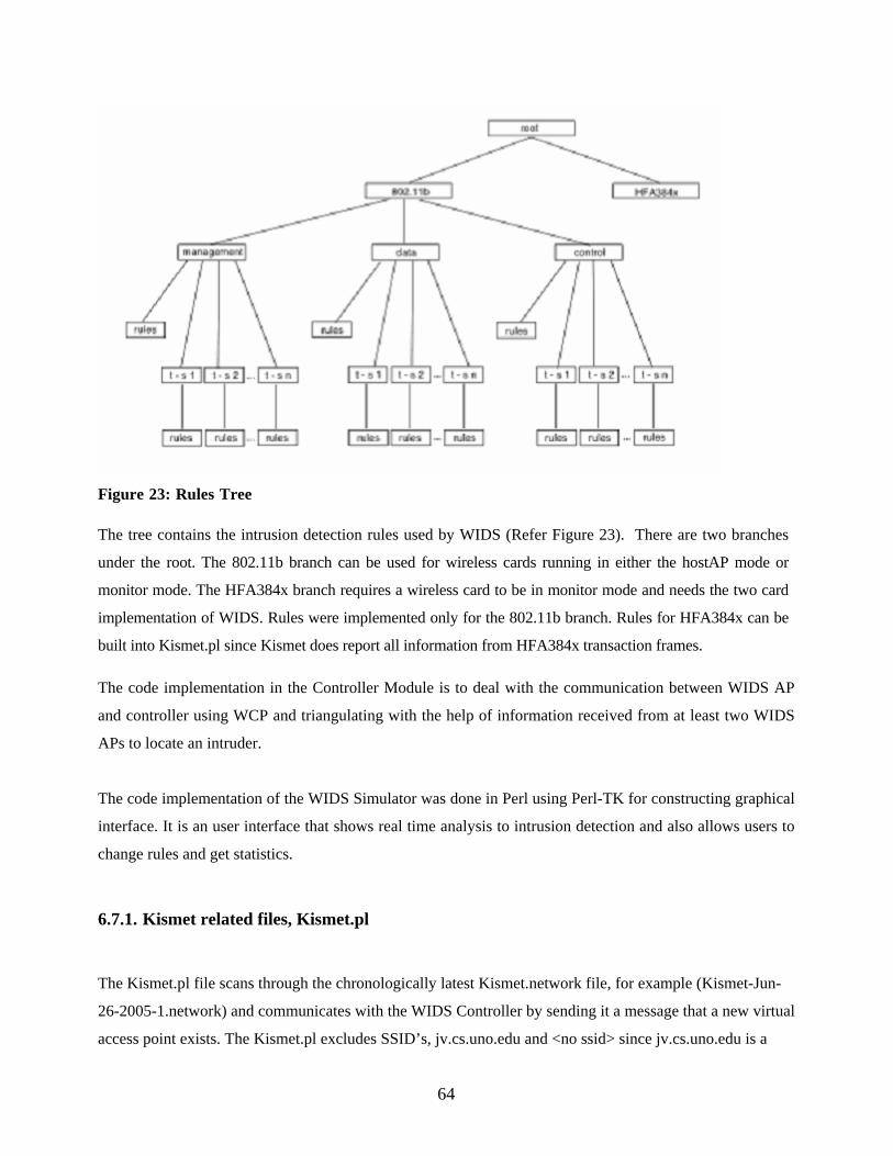
Figure 23: Rules Tree The tree contains the intrusion detection rules used by WIDS (Refer Figure 23). There are two branches
under the root. The 802.11b branch can be used for wireless cards running in either the hostAP mode or
monitor mode. The HFA384x branch requires a wireless card to be in monitor mode and needs the two card
implementation of WIDS. Rules were implemented only for the 802.11b branch. Rules for HFA384x can be
built into Kismet.pl since Kismet does report all information from HFA384x transaction frames. The code implementation in the Controller Module is to deal with the communication between WIDS AP
and controller using WCP and triangulating with the help of information received from at least two WIDS
APs to locate an intruder.
The code implementation of the WIDS Simulator was done in Perl using Perl-TK for constructing graphical
interface. It is an user interface that shows real time analysis to intrusion detection and also allows users to
change rules and get statistics.
6.7.1. Kismet related files, Kismet.pl
The Kismet.pl file scans through the chronologically latest Kismet.network file, for example (Kismet-Jun-
26-2005-1.network) and communicates with the WIDS Controller by sending it a message that a new virtual
access point exists. The Kismet.pl excludes SSID’s, jv.cs.uno.edu and <no ssid> since jv.cs.uno.edu is a
64

WIDS AP and Kismet finds it and <no ssid> is a cloaked AP and there is a need to wait for Kismet to de-
cloak it. It only reports access points running in infrastructure mode. The WIDS Controller graphical
interface is a simple X and Y axis grid with a minimum value of 0 and maximum value of 540 for both X
and Y axis. The X and Y locations of the access points are created through a random function that keeps the
numbers created with in the max range of the WIDS GUI which is 540 on X and Y directions and outside of
the inner perimeter. These locations are generated randomly since I did not use directional antenna to
calculate the locations. The ports on which the access points connect to the WIDS controller are also
generated randomly.
The Kismet.pl can be run on a scheduled Cron job every five minutes.
6.8. WIDS Controller Module
This module performs all the core central functions with respect to detecting intruders by communicating
with other WIDS APs to change angle or direction of sweep and also the controller consists of a real time
analysis user interface that shows all the WIDS APs and also the current sweep routines performed by
WIDS APs. The controller module is written in Perl and uses Perl-TK for constructing the graphical
interface.
Two of the controller’s responsibilities are to provide the access points with information needed to
configure/reconfigure the directional antenna and to provide the intrusion detection rules for the access
point. The controller reads a configuration file at startup. The configuration file contains a hash of
HostAP/WIDS AP names and their beginning sweep positions, ending sweep positions, and report rates, a
hash of internal (non-WIDS) access points and their locations, the size of the grid for specifying access
point locations and a hash of the HostAP/WIDS AP names and their related locations, a numerical ID, and
the midpoint of the beginning and ending sweep positions. The access points ID’s are numbers starting
with 1 for left bottom corner of the perimeter and proceeding in a counterclockwise direction, 2 for the next
access point, 3 for the next access point, etc. until all access points have a number. Numbering in this matter
eliminates the need to consider x and y position values when comparing the location of one access point
compared to the location of another.
After the controller configuration is completed, the controller displays a GUI containing an image of the area
to be protected and the internal non-WIDS access points. The controller opens a socket on a specified port
and listens for messages from the access points. Messages are handled by the WIDS Communication
65

Protocol (WCP) (Refer section 6.5). WIDS APs are displayed on the GUI as they are connected to the
controller. The position of the antenna of each access point is designated by a sweeping line. The controller
assumes that a station associates with the access point closest to it.
The controller operator can change the rules file, display statistics about the stations connected to the
WIDS AP or query the log file. Screen shots of those operations are shown below.
66

Figure 24: Change rules file
Figure 24 shows the WIDS Controller user select the WIDS AP, HOSTAP and then select the rule files for
that WIDS AP.
67

Figure 25: Show Stats
Figure 25 shows the WIDS Controller user click the Get Stats button on the graphical interface and
then select a WIDS AP with a MAC address ’00:02:2D:2E:5C:61’ and then double click it to see all
the statistics of the WIDS AP.
The controller uses a simple algorithm to determine which access point to reconfigure when a maximum
signal strength position has been received from an access point. If the position is greater than the access
point's sweep midpoint, then the access point with the next highest ID number is reconfigured. If the
position is less than the sweep midpoint, the access point with the next lowest ID number is
68

reconfigured. When maximum signal strength positions for a MAC address are received from two
WIDS access points, the controller can locate the access point's position using trigonometry (the law of
sines and Pythagoras' theorem). The graphical interface draws a square (red) at the calculated location
of the intruder.
6.9. WIDS Simulator Module
The WIDS system can be run with simulated access points and simulated stations for testing or
presentation purposes (Refer figures 26 and 27). The simulation handles up to sixteen WIDS
access points. The WIDS access points can be either real (non-simulated) WIDS/HostAP access
points, simulated access points or a combination of the two. If real WIDS/HostAP access points are
used in the simulation, real stations can associate with them. The simulation does not handle
simulated stations associating with a non-simulated WIDS/HostAP access point.
The simulation is written in Perl using Perl-TK for creating the graphical interface. The simulation
can be run on the same computer as the controller, the same computer as a real WIDS/HostAP
access point, or a separate computer. It can be run from a command line or from a GUI. Use of the
GUI requires a configuration file giving geometry for locating windows and a hash of commands for
starting access points, controller, and virtual station. Other information in the simulation
configuration file is controller IP and port for listening, access point name, access point port, delay
per degree value, location, name of file containing simulated antenna readings, and an association
allowed value. The delay per degree value determines the sweep speed of the simulated antenna. The
association allowed determines if clients can associate with the access point.
If the simulation is run on the same computer as the controller or a real WIDS/HostAP access
points, the performance of the WIDS system may decline significantly.
Figure 26: WIDS Simulation Control GUI
69

Figure 27: WIDS simulation with sixteen simulated access points
6.9.1. WIDS Simulated Access Point
A WIDS simulated access point associates with a real (non-simulated) controller and receives no
802.11b frames. A simulated access point has all the functionality of a real WIDS/HostAP access
point except it doesn't process or test rules, the only 802.11b type/subtypes implemented are
associate and disassociate, and it doesn't compute the maximum signal strength location using least
squares regression [28]. It just picks the position of the maximum value signal strength as a position
with POINTS/2 increasing trend on one side and POINTS/2 decreasing trend on other side [28].
6.9.2. WIDS Simulated Station
The simulated station configuration file contains a hash of MAC addresses, locations, show up begin
time in seconds and show up end time in seconds, a list of IP:port pairs representing simulated
70

access points, the time between associates, and the timeframe that a station attempts to associate.
The timeframe is designated by BEGIN and END in the configuration file. A station appears at
BEGIN seconds after the virtual station simulation is started and ends END seconds after the virtual
station simulation is started. The simulation sends ASSOCIATE messages to the list of IP:port pairs
for simulated stations whose timeframe is in effect. The rate of sending the ASSOCIATE messages is
determined by the time between associates value in the configuration file.
6.9.3. WIDS Simulation
The WIDS Simulation was written by Dr. Richard Golden III and the Hostap code changes and
additions were done by John Louis Vigo Jr [28]. I have implemented the extension of WIDS to
include Kismet [24] compatibility and allow WIDS Access Points to also be able to work in RF
Monitor mode without affecting any functionality of the basic HostAP mode by having two separate
NICs, one in HostAP mode and the other in RF Monitor mode. Since the WIDS Access points work
in RF Monitor mode also, I am able to extend WIDS functionality to 802 1.X and 802.11 i networks.
I have referred to a number of experiments with directional antennae [23] in order to characterize the
locations of wireless STAs based on signal strength and antenna bearing. In addition, I have created a
simulation of the WIDS system, written entirely in portable Perl using Perl-TK for graphical
interfaces. The WIDS simulator (Refer Figure 28), where four WIDS APs (arranged vertically, on the
right, blue in the simulator) are protecting an internal WLAN installed in an arena (depicted as a set
of six APs in the center of the diagram). Arrows originating from each WIDS AP show the current
orientation of an attached directional antenna. The other lines emanating from each WIDS AP are
estimates of an intruder’s location; intruders are squares (in red in the simulator) on the exterior of the
arena. The external dots (in purple in the simulator) are external/rogue access points that have
surfaced in the outside perimeter. These external access points are detected by the wireless card
running Kismet in RF Monitor mode.
71
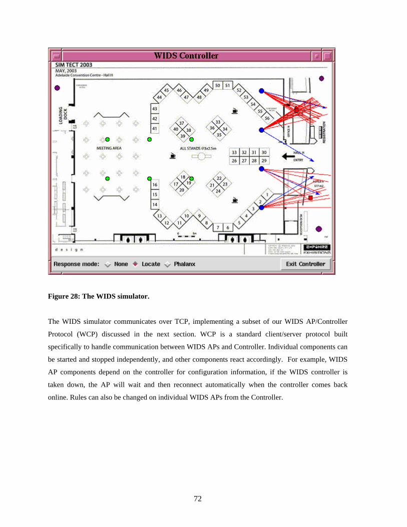
Figure 28: The WIDS simulator.
The WIDS simulator communicates over TCP, implementing a subset of our WIDS AP/Controller
Protocol (WCP) discussed in the next section. WCP is a standard client/server protocol built
specifically to handle communication between WIDS APs and Controller. Individual components can
be started and stopped independently, and other components react accordingly. For example, WIDS
AP components depend on the controller for configuration information, if the WIDS controller is
taken down, the AP will wait and then reconnect automatically when the controller comes back
online. Rules can also be changed on individual WIDS APs from the Controller.
72

Chapter 7. DEFENSE MECHANISMS OF WIDS
I have discussed various attacks on 802.11 and 802.1 X networks in previous chapters. This chapter
discusses how WIDS detects and handles those attacks. As mentioned earlier I have not implemented
WIDS as a HoneyPot [16], so all STAs and APs outside the perimeter are considered a threat to the
internal network. WIDS tracks and locates attackers, even if they are ineffective.
Taking advantage of the two NICs (one running in HostAP mode and other in RF Monitor mode)
implementation, the WIDS AP transforms into a very powerful intrusion detection tool. The HostAP
mode permits WIDS AP to perform a plethora of functions for example logging data, deny access,
apply specific rules and produce alerts. The RF Monitor mode permits WIDS AP to work as a stealthy
passive sniffer. WIDS AP in conjunction with Kismet [24] helps gather raw real time data and
analyze using Ethereal [25] and also detect rogue APs outside of the perimeter.
7.1. NetStumbler Detection (Eavesdropping)
One of the most commonly used tool for war driving is NetStumbler. There are two ways of detecting
NetStumbler. One way uses the wireless NIC in HostAP mode and the other uses the wireless NIC in
RF Monitor mode. The quickest way to detect NetStumbler is through the RF Monitor mode
and Kismet has an in built NetStumbler detection rule.
NetStumbler is detected through Host AP mode since it queries the AP by issuing a data frame with
the protocol, Organizationally Unique Identifier (OUI) value of 0x00601d and protocol id of 0x0001.
This packet also contains a payload string of size 58 bytes that can be put into the NetStumbler
detection rule to identify the version of NetStumbler:
NetStumbler Version Payload String
• 3.2.0 -- Flurble gronk bloopit, bnip Frundletrune
• 3.2.3 -- All your 802.11b are belong to us
• 3.3.0 -- intentionally blank
73

7.2. Denial of Service Attacks
The most common DoS attack is to send continuous disassociation messages. WIDS can keep a track
of the continuous flow of disassociation frames from a particular MAC address and a rule can be set
up to send a disassociate message to the malicious NIC or AP after N number of continuous
disassociation attempts (Refer Figure 29).
Figure 29: Continuous Flow of Deauthentiction/Disassociation Messages
WIDS cannot provide a detection mechanism for Virtual Carrier Sense Attack and
PLME_DSSSTESTMODE (Jamming) Attack. Both of the above attacks make the wireless medium
act busy and thus not available to any STA or AP within range. The WIDS AP and Controller
communicate with one another through a wired medium and the attack does not cause any
interference to the wired medium but since the wireless medium is rendered busy the WIDS AP can
not calculate the location of the intruder.
74

7.3. MAC Spoofing – Identity Theft
I am aware that MAC addresses can very easily be spoofed. Let me give you an example. The MAC
address of a NIC can be changed using the ‘iwconfig’ utility from wireless utilities. WIDS has a list
of vendor names that manufacture NIC’s and each manufacturer is allowed to assign a MAC address
between a certain range of MAC addresses.
WIDS logs every MAC address and cross checks the MAC address with the above list and raises an
alert if the rule fails. If an attacker spoofs the MAC address of a NIC with another MAC address
which is in the same range as required for the manufacturer we can still detect by noticing the change
in sequence on Sequence Numbers in MAC frame.
7.4. Session Hijacking
WIDS is an external layer of protection and WIDS AP’s face the first line of attack with respect to a
session hijack attempt. The WIDS AP is able to address the issue of spoofed MAC addresses and is
able to quickly detect such an attempt (Refer to previous section). Since the disassociate request
comes from an AP with spoofed MAC address the WIDS AP immediately issues a return request to
the malicious AP to disassociate. Hence it will prevent the session hijack attempt.
WIDS is a very useful active intrusion detection system and I have extended the implementation of
WIDS AP from a single NIC running in HostAP mode to use two NICs (one running HostAP mode
and the other running RF Monitor mode). This work and merging of Kismet into the WIDS family
was a comprehensive part of my thesis. Other intrusion detection systems either work in the Master
mode or in RF Monitor mode at a given point of time but WIDS always runs in dual mode.
75

Chapter 8. TESTING AND RESULTS
WIDS has been tested at various stages of development and I have devised a thorough and complete
test for WIDS to track and locate unauthorized STAs and external/rogue APs.
8.1 Test - Locating Intruders and External/Rogue Access Points 8.1.1 Test Description There are two neighboring access points connected to the controller. One is a real (non-simulated)
WIDS AP access point, named HOSTAP, and the other is a simulated access point, named BETA,
running on the same computer as the WIDS AP access point.
The real station with MAC address 00:02:2D:2E:5C:61 associates with the real WIDS AP access
point. This is a real association and not simulated. The rules are applied to the 802.11 frames received
from the real station. The WIDS AP access point computes the position of the station
00:02:2D:2E:5C:61 maximum signal strength using the data in its simulated antenna readings file and
sends it to the controller. The WIDS controller reconfigures the simulated access point sweep arch.
The simulated access point computes the position of the station 00:02:2D:2E:5C:61 maximum
signal strength using the data in its simulated antenna readings file and sends it to the controller.
The controller computes the position of the station 00:02:2D:2E:5C:61 from the data received
from the two access points.
In order to test the IP packet reading rule, the station 00:02:2D:2E:5C:61 pings the WIDS/HostAP
access point. Four pings were sent from the station.
The controller should also show two networks outside the perimeter. These are external/rogue access
points detected by Kismet running in passive monitor mode on the HostAP machine.
76
8.1.2 Hardware Used for the Test One IBM ThinkPad Pentium III 450 MHz, 128 Mb memory laptop with a Linksys Instant
Wireless WPC11 wireless card (MAC address 00:04:5a:0c:d8:0c) running Linux and HostAP used
for a WIDS/HostAP access point and a Lucent Technologies Orinoco Silver 11 Mbits/s wireless
card (MAC address 00:02:2d:2e:5b:f6) running Kismet in Monitor mode.
One generic Pentium 4 266 GHz, 512 Mb memory laptop with an Lucent Technologies Orinoco
Silver 11 Mbits/s wireless card (MAC address 00:02:2D:2E:5C:61) address running WindowsXP
used for a station connecting to the WIDS/HostAP access point.
One IBM ThinkPad Pentium III 450 MHz, 128 Mb memory laptop running Linux used for the
controller.
One Laplink Cable (Parallel Port connection cable) connecting the WIDS/HostAP access
point and the controller (A Laplink cable was used instead of an Ethernet hub to connect the
WIDS/HostAP access point and the controller since I wanted to free the second PCMCIA slot
used by the PCMCIA Ethernet card and use it for a Wireless Card to run Kismet in RF Monitor
mode).
8.1.3 Expected Results for the Test The rule
“MGMT_ASREQ,(FLAG_RETRY:OFF!SOURCE_MAC_EQUALS:00022D2E5C61!),
LOG,FLAG RETRY Off” should be true. The controller log should show an entry for HOSTAP
with a message including the date and time and “FLAG RETRY Off, Association Req.”. Logging the
association request attempt is very useful to keep track of STAs trying to associate with an AP.
The rule “MGMT_AUTH,(SOURCE_MAC_EQUALS:00022D2E5C61!TTL_EQUALS:64!
FLAG_RETRY:OFF!),LOG, 02 2d 2e 5c 61 authenticated with ttl = 64” should be true. The
controller log should show an entry for HOSTAP with a message including the date and time and “02
2d 2e 5c 61 authenticated with ttl = 64, Authentication.” Since four pings are sent with TTL= 64,
the log should show four messages.
All other rules are false and no action should be taken.
77

The controller log should show association messages with dates and times for station
00:02:2d:2e:5c:61 with an Agere Systems wireless card.
The WIDS/HostAP log should show messages sent to the controller as a result of the rules. HostAP
logs all authentications and associations in the /var/log/messages log. There should be messages with
times and dates for authentication and association for station 00:02:2D:2E:5C:61.
Simulated antenna position of simulated access point BETA antenna when maximum signal received
from station 00:02:2D:2E:5C:61 is 63 degrees. Simulated antenna position of HostAP access point
HOSTAP antenna when maximum signal received from station 00:02:2D:2E:5C:61 is -25 degrees.
The station is located at (452.94, 334.64).
Pings will be sent from 00:02:2D:2E:5C:61 with TTL = 64. HostAP and controller logs should show
test results for IP headers from 00:02:2D:2E:5C:61.
Kismet should find three rogue networks ‘Mine’, ‘My Home’ and ‘LASSI’ outside of the perimeter. 8.1.4 Results of the Test The controller log shows only the two lines expected as results of the intrusion detection rules
(times are gm time):
HOSTAP Sun June 26 02:48:13 2005 FLAG RETRY Off Association Req HOSTAP Sun June 26 02:51:56 2005 02 2d 2e 5c 61 authenticated with ttl = 64 Authentication
The controller log shows the expected association messages from the two stations: HOSTAP Sun June 26 02:48:16 2005 associated with 00:02:2d:2e:5c:61 wireless card Agere Systems The WIDS/HostAP log shows messages: Sat June 25 21:48:13 2005 ,FLAG RETRY Off,Association Req Sat June 25 21:51:57 2005 , 02 2d 2e 5c 61 authenticated with ttl = 64,Authentication
The HostAP access point /var/log/messages log shows authentication and association of station
78

00:02:2d:2e:5c:61. June 25 21:48:13 localhost hostapd: wlan0: STA 00:02:2d:2e:5c:61 IEEE 802.11: authenticated June 25 21:48:13 localhost hostapd: wlan0: STA 00:02:2d:2e:5c:61 IEEE 802.11: associated (aid 1)
The controller received the antenna position of 63 degrees for simulated access point BETA antenna
when the maximum signal message was received from station 00:02:2D:2E:5C:61 and the antenna
position of -25 degrees for HostAP access point HOSTAP antenna when maximum signal received
message was received from station 00:02:2D:2E:5C:61:
WIDS controller received client located at -25 (angle) from HOSTAP WIDS controller received client located at 63 (angle) from BETA
The controller is an (X, Y) grid and shows the computed station’s location rounded to two decimals as (452.94, 334.64): ALERT client found at x = 452.936474021111 y = 334.641469930032 HostAP and Controller logs show test results for IP headers from 00:02:2D:2E:5C:61. As
additional testing on the IP packets, Scoop was run with the print hex option to dump the Ethernet
and IP headers. The hostAP terminal window displayed the following for pings from
00:02:2D:2E:5C:61. Only the ping from 00:02:2D:2E:5C:61 shows a test result as expected. IP: 192.168.0.69 -> 192.168.0.70 (60) id: 15773 ICMP: echo reply 00 0002 2d2e 5c61 0004 5a0c d80c 0800 4500 10 003c 3d9d 0000 4001 bb48 c0a8 0045 c0a8 20 0046 0000 535c 0100 0100 6162 6364 6566 30 6768 696a 6b6c 6d6e 6f70 7172 7374 7576 40 7761 6263 6465 6667 6869 scoop testing packet test result is .... Wed June 25 21:51:56 2005 , 02 2d 2e 5c 61 authenticated with ttl = 64,Authentication log action 02 2d 2e 5c 61 authenticated with ttl = 64 IP: 192.168.0.69 -> 192.168.0.70 (60) id: 15774 ICMP: echo reply 00 0002 2d2e 5c61 0004 5a0c d80c 0800 4500 10 003c 3d9e 0000 4001 bb47 c0a8 0045 c0a8 … Kismet finds three rogue networks. Kismet does also find the networks, jv.cs.uno.edu and <no ssid>
but does not report it to the controller since jv.cs.uno.edu is a WIDS AP and <no ssid> is a hidden
network with the SSID ‘LASSI’ which after a certain time is de-cloaked by Kismet (Refer Figure 30).
79

Figure 30: Networks found by Kismet.
The following are other screen shots of Kismet :
Figure 31: Kismet found networks with statistics.
Kismet provides statistics with respect to the networks that were found. It shows how many APs that
were have WEP enabled, channel usage of each AP and total number of packets collected (Refer
80

Figure 31).
Figure 32: Kismet found networks with Packet Types.
Kismet also provides a screen to see different packet types associated with name of the AP and MAC
address (Refer Figure 32).
81

Figure 33: Kismet found Networks with one de-cloaked network ‘LASSI’.
Finally Kismet has found three rogue APs and all the three rogue APs have WEP enabled (Refer
Figure 33).
8.1.5 Data Files used for Test 8.1.5.1 Rules File for the Test The rules file contains a set of rules that need to be tested for a WIDS AP. The rules files I have used
for the test is as follows:
MGMT_ASREQ,(FLAG_RETRY:OFF!SOURCE_MAC_EQUALS:00022D2E5C61!),LOG,FLAG RETRY Off MGMT_ASREQ,(FLAG_RETRY:ON!SOURCE_MAC_EQUALS:00022D2E5C61!),LOG,FLAG RETRY On MGMT_ASREQ,(DEST_MAC_EQUALS:00022D2E5C61!),LOG,assoc request dest mac 00 02 2d 2e 5c 61 MGMT_AUTH,(SOURCE_MAC_EQUALS:00022D2E5C61!TTL_EQUALS:64!FLAG_RETRY:OFF!),LOG, 02 2d 2e 5c 61 authenticated with ttl = 64
82

8.1.5.2 Access Point MAC Address 00:02:2D:2E:5C:61 Antenna Readings File
WIDS does not have rotational directional antenna capability, hence I used an antenna readings file
for WIDS AP HOSTAP to perform the test. The antenna readings file is as follows: filename "angle4" # format for a reading is degrees,signal strength;mac address, # first number represents the angle in degrees. The second number represents # the signal strength. # next 6 numbers represent mac address. Each reading must be separated by ',' # or '/n' and there must be a '\n' before the EOF character # comments start with '#' and the '#' is allowed only at start of line -35,10;00:02:2D:2E:5C:61,-34,12;00:02:2D:2E:5C:61,-33,16;00:02:2D:2E:5C:61,- 32,20;00:02:2D:2E:5C:61,-31,23;00:02:2D:2E:5C:61,-30,25;00:02:2D:2E:5C:61,- 29,27;00:02:2D:2E:5C:61,-28,24;00:02:2D:2E:5C:61,-27,27;00:02:2D:2E:5C:61,- 26,28;00:02:2D:2E:5C:61,-25,29;00:02:2D:2E:5C:61,-24,26;00:02:2D:2E:5C:61,- 23,27;00:02:2D:2E:5C:61,-22,25;00:02:2D:2E:5C:61,-21,23;00:02:2D:2E:5C:61,- 20,20;00:02:2D:2E:5C:61,-19,16;00:02:2D:2E:5C:61,-18,14;00:02:2D:2E:5C:61,- 17,12;00:02:2D:2E:5C:61
8.1.5.3 Simulated Access Point (BETA) Antenna Readings File
WIDS does not have rotational directional antenna capability, hence I used an antenna readings file
for WIDS AP BETA to perform the test. The antenna readings file is as follows: filename "data8" 57,32;00:02:2D:2E:5C:61 58,33;00:02:2D:2E:5C:61 59,38;00:02:2D:2E:5C:61 60,40;00:02:2D:2E:5C:61 61,44;00:02:2D:2E:5C:61 62,45;00:02:2D:2E:5C:61 63,47;00:02:2D:2E:5C:61 64,44;00:02:2D:2E:5C:61 65,43;00:02:2D:2E:5C:61 66,41;00:02:2D:2E:5C:61 67,30;00:02:2D:2E:5C:61 68,29;00:02:2D:2E:5C:61
83

8.1.5.4 Kismet Output Network File
The output file from Kismet will be used by Kimset.pl to report to the Controller information about all
the external/rogue access points found by Kismet. The sample file is as follows :
Network 1: "mine" BSSID: "00:0F:66:39:47:52" Type : infrastructure Carrier : 802.11b Info : "None" Channel : 11 WEP : "Yes" Maxrate : 54.0 LLC : 2213 Data : 94 Crypt : 94 Weak : 0 Total : 2307 First : "Sun Jun 26 10:54:48 2005" Last : "Sun Jun 26 14:16:50 2005" Network 2: "LASSI" BSSID: "00:09:5B:DA:71:48" Type : infrastructure Carrier : 802.11b Info : "None" Channel : 11 WEP : "Yes" Maxrate : 11.0 LLC : 5448 Data : 0 Crypt : 0 Weak : 0 Total : 5448 First : "Sun Jun 26 10:54:48 2005" Last : "Sun Jun 26 14:16:51 2005" Network 3: "jv.cs.uno.edu" BSSID: "00:04:5A:0C:D8:0C" Type : infrastructure Carrier : 802.11b Info : "None" Channel : 03 WEP : "No" Maxrate : 11.0 LLC : 50 Data : 0 Crypt : 0 Weak : 0 Total : 50 First : "Sun Jun 26 10:55:20 2005" Last : "Sun Jun 26 14:15:15 2005" Network 4: "My Home" BSSID: "00:09:5B:EB:3A:94" Type : infrastructure Carrier : 802.11b
84
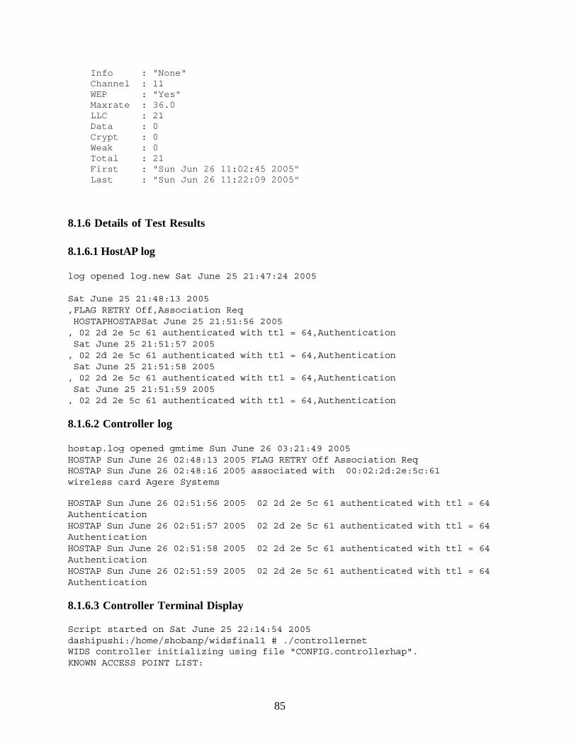
Info : "None" Channel : 11 WEP : "Yes" Maxrate : 36.0 LLC : 21 Data : 0 Crypt : 0 Weak : 0 Total : 21 First : "Sun Jun 26 11:02:45 2005" Last : "Sun Jun 26 11:22:09 2005" 8.1.6 Details of Test Results 8.1.6.1 HostAP log log opened log.new Sat June 25 21:47:24 2005
Sat June 25 21:48:13 2005 ,FLAG RETRY Off,Association Req HOSTAPHOSTAPSat June 25 21:51:56 2005 , 02 2d 2e 5c 61 authenticated with ttl = 64,Authentication Sat June 25 21:51:57 2005 , 02 2d 2e 5c 61 authenticated with ttl = 64,Authentication Sat June 25 21:51:58 2005 , 02 2d 2e 5c 61 authenticated with ttl = 64,Authentication Sat June 25 21:51:59 2005 , 02 2d 2e 5c 61 authenticated with ttl = 64,Authentication
8.1.6.2 Controller log hostap.log opened gmtime Sun June 26 03:21:49 2005 HOSTAP Sun June 26 02:48:13 2005 FLAG RETRY Off Association Req HOSTAP Sun June 26 02:48:16 2005 associated with 00:02:2d:2e:5c:61 wireless card Agere Systems HOSTAP Sun June 26 02:51:56 2005 02 2d 2e 5c 61 authenticated with ttl = 64 Authentication HOSTAP Sun June 26 02:51:57 2005 02 2d 2e 5c 61 authenticated with ttl = 64 Authentication HOSTAP Sun June 26 02:51:58 2005 02 2d 2e 5c 61 authenticated with ttl = 64 Authentication HOSTAP Sun June 26 02:51:59 2005 02 2d 2e 5c 61 authenticated with ttl = 64 Authentication
8.1.6.3 Controller Terminal Display Script started on Sat June 25 22:14:54 2005 dashipushi:/home/shobanp/widsfinal1 # ./controllernet WIDS controller initializing using file "CONFIG.controllerhap". KNOWN ACCESS POINT LIST:
85

CTR CBR PINKY CTL CBL LAP1 BAP1 BAP3 ALPHA BAP2 BETA HOSTAP TAP2 LAP3 LAP2 TAP1 WIDS controller configuration complete. WIDS controller bringing up GUI. WIDS controller: Image is 600 x 416. WIDS controller listening on port 7777. WIDS controller got connection. WIDS controller sending CONFIG to BETA. WIDS controller configured BETA, located @ (420,270). WIDS controller got connection. WIDS controller sending CONFIG to HOSTAP. WIDS controller configured HOSTAP, located @ (420,350). WIDS controller logging HOSTAP Sun June 26 02:48:13 2005 FLAG RETRY Off Association Req WIDS controller logging HOSTAP Sun June 26 02:48:16 2005 associated with 00:02:2d:2e:5c:61 wireless card Agere Systems WIDS controller received client located at -25 (angle) from HOSTAP adding to hash 00:02:2D:2E:5C:61 HOSTAP;-25;1 SENDING RECONFIG to BETA POS = -25 -45 90 2 WIDS controller received client located at 63 (angle) from BETA locating ap name1= BETA,position1= 63, name2 =HOSTAP, position2= -25, ap1x=420 ap1y=270 ALERT client found at x = 452.936474021111 y = 334.641469930032 WIDS controller received client located at -25 (angle) from HOSTAP WIDS controller logging HOSTAP Sun June 26 02:51:56 2005 02 2d 2e 5c 61 authenticated with ttl = 64 Authentication WIDS controller logging HOSTAP Sun June 26 02:51:57 2005 02 2d 2e 5c 61 authenticated with ttl = 64 Authentication WIDS controller logging HOSTAP Sun June 26 02:51:58 2005 02 2d 2e 5c 61 authenticated with ttl = 64 Authentication WIDS controller logging HOSTAP Sun June 26 02:51:59 2005 02 2d 2e 5c 61 authenticated with ttl = 64 Authentication WIDS controller received client located at -25 (angle) from HOSTAP Use of uninitialized value in concatenation (.) or string at wids.pl line 466,
86

<RULES> line 6. mesg not defined type = ** OTHER SIDE HUNG UP 11111 ** WIDS controller received client located at -25 (angle) from HOSTAP Use of uninitialized value in concatenation (.) or string at wids.pl line 466, <RULES> line 6. mesg not defined type = ** OTHER SIDE HUNG UP 11111 ** Script done on Sat June 25 22:41:27 2005 The “use of unitialized value …” and “mesg not defined type = “ comments are results of the access points shutting down 8.1.6.4 HostAP terminal Script started on Sat June 25 21:25:54 2005]0;root@localhost:/home/jvigo/hostap-0.0.3/hostapd2new_shared4_clean1 [root@localhost hostapd2new_shared4_clean1]# ./hostapd hostapddashipushi.conf Configuration file: hostapddashipushi.conf table_alloc done table_alloc rule done could not insert in table: key exists and no overwrite,key=00:01:C8, c= 915 could not insert in table: key exists and no overwrite,key=08:00:30, c= 14393 could not insert in table: key exists and no overwrite,key=08:00:30, c= 14395
log opened log.new Sat June 25 21:47:24 2005 HOSTAP;17;log opened ;Sun June 26 02:47:24 2005 ip add= 192.168.1.4, port 7777 WIDS AP HOSTAP connecting to CONTROLLER @ 192.168.1.4:7777. controller registered sockfd= 4 hostap AP HOSTAP sending initial HELLO to WIDS controller. WIDS hostap HOSTAP waiting for CONFIG message. message = CONTROLLER;2;- 45;45;2;MGMT_ASREQ,(FLAG_RETRY:OFF!SOURCE_MAC_EQUALS:00022D2E5C61!),LOG,FLAG RETRY Off MGMT_ASREQ,(FLAG_RETRY:ON!SOURCE_MAC_EQUALS:00022D2E5C61!),LOG,FLAG RETRY On MGMT_ASREQ,(DEST_MAC_EQUALS:00022D2E5C61!),LOG,assoc request dest mac 00 02 2d 2e 5c 61 MGMT_AUTH,(SOURCE_MAC_EQUALS:00022D2E5C61!TTL_EQUALS:64!FLAG_RETRY:OFF!),LOG, 02 2d 2e 5c 61 authenticated with ttl = 64 #MGMT_AUTH,(SOURCE_MAC_EQUALS:000D884BE0D6!TTL_EQUALS:64!FLAG_RETRY:OFF!),LOG, 00:0d:88:4b:e0:d6 authenticated with ttl = 64
87

#MGMT_AUTH,(SOURCE_MAC_EQUALS:00022D2E5C61!TTL_EQUALS:64!FLAG_RETRY:OFF!),DISA SSOC, 02 2d 2e 5c 61 disassociated with ttl = 64
hostap AP HOSTAP received CONFIG: sweep -45 - 45, report rate 2 processing rules Using interface wlan0ap with hwaddr 00:04:5a:0c:d8:0c and ssid 'jv.cs.uno.edu' Flushing old station entries Deauthenticate all stations ieee802_11.c 10 /nieee802_11.c auth failed wlan0: STA 00:02:2d:2e:5c:61 IEEE 802.11: authenticated do auth stuff here Sat June 25 21:48:13 2005 ,FLAG RETRY Off,Association Req log action FLAG RETRY Off wlan0: STA 00:02:2d:2e:5c:61 IEEE 802.11: associated (aid 1) do associate stuff here get ant readings simulated antenna readings ok Modified Scoop 1.0 [IP packet sniffing tool] <ctrl-c> to quit scoop pid = 1304 HOSTAP AP HOSTAP got ASSOCIATE from 00:02:2d:2e:5c:61, signal=120 @ position unknown HOSTAPieee802_11.c 10 /nieee802_11.c auth failed wlan0: STA 00:0d:88:4b:e0:d6 IEEE 802.11: authenticated do auth stuff here ieee802_11.c 10 /nieee802_11.c auth failed wlan0: STA 00:0d:88:4b:e0:d6 IEEE 802.11: authenticated do auth stuff here wlan0: STA 00:0d:88:4b:e0:d6 IEEE 802.11: associated (aid 2) do associate stuff here get ant readings simulated antenna readings ok HOSTAP AP HOSTAP got ASSOCIATE from 00:0d:88:4b:e0:d6, signal=0 @ position unknown HOSTAPmax signal is at -25.6176 sig= 29 max signal is at -25.6176 sig= 29 IP: 192.168.0.69 -> 192.168.0.70 (60) id: 15773 ICMP: echo reply 00 0002 2d2e 5c61 0004 5a0c d80c 0800 4500 10 003c 3d9d 0000 4001 bb48 c0a8 0045 c0a8 20 0046 0000 535c 0100 0100 6162 6364 6566 30 6768 696a 6b6c 6d6e 6f70 7172 7374 7576 40 7761 6263 6465 6667 6869 scoop testing packet test result is .... Sat June 25 21:51:56 2005 , 02 2d 2e 5c 61 authenticated with ttl = 64,Authentication log action 02 2d 2e 5c 61 authenticated with ttl = 64 IP: 192.168.0.69 -> 192.168.0.70 (60) id: 15774 ICMP: echo reply 00 0002 2d2e 5c61 0004 5a0c d80c 0800 4500
88

10 003c 3d9e 0000 4001 bb47 c0a8 0045 c0a8 20 0046 0000 525c 0100 0200 6162 6364 6566 30 6768 696a 6b6c 6d6e 6f70 7172 7374 7576 40 7761 6263 6465 6667 6869 scoop testing packet test result is .... Sat June 25 21:51:57 2005 , 02 2d 2e 5c 61 authenticated with ttl = 64,Authentication log action 02 2d 2e 5c 61 authenticated with ttl = 64 IP: 192.168.0.69 -> 192.168.0.70 (60) id: 15775 ICMP: echo reply 00 0002 2d2e 5c61 0004 5a0c d80c 0800 4500 10 003c 3d9f 0000 4001 bb46 c0a8 0045 c0a8 20 0046 0000 515c 0100 0300 6162 6364 6566 30 6768 696a 6b6c 6d6e 6f70 7172 7374 7576 40 7761 6263 6465 6667 6869 scoop testing packet test result is .... Sat June 25 21:51:58 2005 , 02 2d 2e 5c 61 authenticated with ttl = 64,Authentication log action 02 2d 2e 5c 61 authenticated with ttl = 64 IP: 192.168.0.69 -> 192.168.0.70 (60) id: 15776 ICMP: echo reply 00 0002 2d2e 5c61 0004 5a0c d80c 0800 4500 10 003c 3da0 0000 4001 bb45 c0a8 0045 c0a8 20 0046 0000 505c 0100 0400 6162 6364 6566 30 6768 696a 6b6c 6d6e 6f70 7172 7374 7576 40 7761 6263 6465 6667 6869 scoop testing packet test result is .... Sat June 25 21:51:59 2005 , 02 2d 2e 5c 61 authenticated with ttl = 64,Authentication log action 02 2d 2e 5c 61 authenticated with ttl = 64 IP: 192.168.0.69 -> 192.168.0.71 (60) id: 3257 ICMP: echo reply 00 000d 884b e0d6 0004 5a0c d80c 0800 4500 10 003c 0cb9 0000 4001 ec2b c0a8 0045 c0a8 20 0047 0000 535c 0100 0100 6162 6364 6566 30 6768 696a 6b6c 6d6e 6f70 7172 7374 7576 40 7761 6263 6465 6667 6869 scoop testing packet IP: 192.168.0.69 -> 192.168.0.71 (60) id: 3258 ICMP: echo reply 00 000d 884b e0d6 0004 5a0c d80c 0800 4500 10 003c 0cba 0000 4001 ec2a c0a8 0045 c0a8 20 0047 0000 525c 0100 0200 6162 6364 6566 30 6768 696a 6b6c 6d6e 6f70 7172 7374 7576 40 7761 6263 6465 6667 6869scoop testing packet IP: 192.168.0.69 -> 192.168.0.71 (60) id: 3259 ICMP: echo reply 00 000d 884b e0d6 0004 5a0c d80c 0800 4500 10 003c 0cbb 0000 4001 ec29 c0a8 0045 c0a8 20 0047 0000 515c 0100 0300 6162 6364 6566 30 6768 696a 6b6c 6d6e 6f70 7172 7374 7576 40 7761 6263 6465 6667 6869 scoop testing packet
89

IP: 192.168.0.69 -> 192.168.0.71 (60) id: 3260 ICMP: echo reply 00 000d 884b e0d6 0004 5a0c d80c 0800 4500 10 003c 0cbc 0000 4001 ec28 c0a8 0045 c0a8 20 0047 0000 505c 0100 0400 6162 6364 6566 30 6768 696a 6b6c 6d6e 6f70 7172 7374 7576 40 7761 6263 6465 6667 6869 scoop testing packet max signal is at -25.6176 sig= 29 max signal is at -25.6176 sig= 29 handle term killing 1304 cleaning up shared memory struct eloop.c after loop Removing station 00:0d:88:4b:e0:d6 Removing station 00:02:2d:2e:5c:61 Flushing old station entries Deauthenticate all stations ]0;root@localhost:/home/jvigo/hostap-0.0.3/hostapd2new_shared4_clean1 [root@localhost hostapd2new_shared4_clean1]# [root@localhost hostapd2new_shared4_clean1]# Script done on Wed June 25 21:54:12 2005
8.1.6.5 BETA AP terminal [root@localhost root]# cd /root/wids [root@localhost wids]# perl accesspt2net WIDS AP BETA connecting to controller @ 192.168.1.4:7777. WIDS AP BETA sending initial HELLO to WIDS controller. WIDS AP BETA waiting for CONFIG message. 57,32;00:02:2D:2E:5C:61 adding to allowed mac hash 00:02:2D:2E:5C:61 associate allowed = 1 58,33;00:02:2D:2E:5C:61 59,38;00:02:2D:2E:5C:61 60,40;00:02:2D:2E:5C:61 61,44;00:02:2D:2E:5C:61 62,45;00:02:2D:2E:5C:61 63,47;00:02:2D:2E:5C:61 64,44;00:02:2D:2E:5C:61 65,43;00:02:2D:2E:5C:61 66,41;00:02:2D:2E:5C:61 67,30;00:02:2D:2E:5C:61 68,29;00:02:2D:2E:5C:61 WIDS AP BETA received CONFIG: sweep -45 - 45, report rate 2.WIDS AP BETA listening on port 7001 for virtual client. reconfig message -45 90 2 ap got reconfig vcexists 0 reconf received position -11, begin -45, end 90 at receive reconf in nfound sending position 63, 00:02:2D:2E:5C:61, 0 pos =-45 end = 90 beg = -45 back to original config BETA count = 2 end =45 begin = -45 pos =-45, dir= 1 mac
90

0 [root@localhost wids]# 8.1.6.6 Kismet terminal root@localhost root]# kismet_monitor -H Will launch kismet_hopper Using /usr/local/etc/kismet.conf sources... Enabling monitor mode for an orinoco card on eth0 channel 6 Launching kismet_hopper in the background. /usr/local/bin/kismet_monitor: line 238: test: : integer expression expected [root@localhost root]# Hopping 3 channels per second (333333 microseconds per channel) NOTICE: No enable sources specified, all sources will be enabled. kismet_hopper - Source 0 - Channel hopping (United States) on interface eth0 [root@localhost root]# kismet Server options: none Client options: none Starting server... Will drop privs to jvigo (500) No enable sources specified, all sources will be enabled. Source 0 (Kismet): Using pcap to capture packets from eth0 Dropped privs to jvigo (500) Allowing clients to fetch WEP keys. Logging networks to /home/jvigo/kismet-logs/Kismet-Jun-26-2005-2.network Logging data to /home/jvigo/kismet-logs/Kismet-Jun-26-2005-2.dump Writing data files to disk every 300 seconds. Filtering beacon packets. Reading AP manufacturer data and defaults from /usr/local/etc/ap_manuf Reading client manufacturer data and defaults from /usr/local/etc/client_manuf Dump file format: wiretap (local code) dump Kismet 2.8.1 (Kismet) Source 0 (Kismet): Capturing packets from libpcap device eth0 Logging data networks Listening on port 2501. Allowing connections from 127.0.0.1/255.255.255.255 Registering builtin client/server protocols... Starting UI...
91

8.1.7 Commands to Run Test On HostAP access point laptop: 1. Start simulated access point /root/wids # perl accesspt2net 2. In another terminal window - start hostapd /home/jvigo/hostap-0.0.3/hostapd2new_sharedclean1 # ./hostapd hostapddashipushi.conf 3. Start Kismet Hopper /root# kismet_monitor –H 4. Start Kismet /root# kismet 5. Run iwpriv every 5 secs to get data through monitor mode on eth0 /root# csh /root~ while 1 > while 5 > iwpriv eth0 force_reset > end 6. Run Kismet.pl /root/wids # perl Kismet.pl On controller pc: 1. Start controller /home/shobanp/widsfinal1# ./controllernet
92

8.2 Test Results and Final Comments The test was designed to track and locate an intruder and also detect rogue access points on the outer
perimeter. I used two WIDS APs, a real WIDS AP (HOSTAP) and a simulated WIDS AP (BETA)
and a controller which handles both real and simulated WIDS access points. Antenna information was
simulated by using two antenna readings files for HOSTAP and BETA APs. WIDS was able to track
and locate the intruder and also locate three rogue APs.(Refer Figure 34).
The test produced the expected results and shows that the WIDS software successfully implements
parts of the complete WIDS package. Kismet also detected rogue external/rogue networks. However,
the software needs to be extended to handle the rotating directional antennas and tests of the location
calculations and antenna reconfiguration need to be performed with the actual hardware.
Figure 34: Reconfigured BETA AP and HOSTAP locating station.
93

Chapter 9. CONCLUSIONS
9.1. Conclusions
WIDS system will work very successfully in environments where WLANs requires perimeter
intrusion detection. WIDS is well suited for military environment, navy shipyards and navy ships.
The WIDS system contains three modules, which are WIDS Module, Controller Module and WIDS
Simulator.
The WIDS Module scans actively for malicious NICs or APs with the help of directional
antennas. The WIDS Module has a rules engine and specific rules are stored in a hash so real-time
data can be compared and alerts can be sent as required to the Controller. The Controller Module is a
vital part in the WIDS system. It manages all the WIDS APs and coordinates WIDS APs to
triangulate intruders. The WIDS Simulator is an user interface which allows users to add, edit or
delete rules, get statistics and also has all the WIDS APs visible showing their individual antenna
sweeps.
WIDS is able to detect and defend a WLAN from the most commonly known attacks. Denial of
Service attacks on 802.11 and 802.1 X networks are more frequently used by intruders since these
attacks cause the most inconvenience to the WLAN with respect to basic functionality. WIDS AP’s
are connected to the Controller through wire and when the wireless medium is acting busy due a DoS
(deauthentication/disassociation/jamming) attack, the controller is triggered about the attack and
recognizes that an attack is in progress. The controller then can basically shutdown the wireless
medium. There is no defensive procedure for such DoS attacks yet but the WIDS Simulator can
graphically show which WIDS AP’s are acting busy and the controller can collect further information
from the various WIDS AP’s about time of attack, period the wireless medium is busy etc
WIDS, is one of the few WLAN intrusion detection systems which is built with off-the-shelf
components and also has the functionality to physically locate intruders. All that remains to
complete a WIDS prototype is to build a WIDS AP with an embedded computer and a rotational
antenna and to modify the WIDS HostAP software to control the movement of the antenna.
Even though IEEE802.11 i improves security of wireless networks, there is still a need for additional
security provided by WIDS. Installed wireless networks will not be immediately updated. New
94

hardware is needed for CCMP, which could be expensive for large networks. Since IEEE 802.11 i is
new technology, there can be configuration or implementation errors. Authentication mechanisms can
be compromised by human errors or by lost or stolen equipment.
9.2. Future Research
One of the main topics for future research is the development of a hardware embedded prototype of
the WIDS APs, with moveable directional antennae accompanied with motor control. Other
improvements would be to expand rule processing, implement combination of AND and OR logic,
implement more rule cases and test them.
The controller needs to check for access points that are down and refresh the GUI. It would be
beneficial to implement an Agent Service that is able to perform log data clean up, send email on the
rise of an alert etc.
95
REFERENCES
[1] IEEE. “IEEE 802.11-1999 (ISO/IEC 8802-11: 1999). “Local and metropolitan area networks—
Specific requirements—Part 11: WLAN Medium Access Control (MAC) and Physical Layer (PHY)
Specifications.”
URL: http://standards.ieee.org/reading/ieee/std/lanman/802.11-1999.pdf
[2] IEEE. Standards for local and metropolitan area networks: Standard for port based network access
control. IEEE Draft P802.1 X/D11, March 2001.
[3] IEEE. Standard 802.11 i/D 3.0, Draft supplement to Telecommunications and information
exchange between systems – Local and metropolitan area networks – Specific requirements – Part II:
Wireless LAN Medium Access Control (MAC) and Physical Layer (PHY) Specifications:
Specification for Enhanced Security, Marraskuu 2002.
[4] Robert Foust, “Identifying and Tracking Unauthorized 802.11 Cards and Access Points, A
Practical Approach,”;login:, 27(4), August 2002.
[5] Fluher, S., Mantin, I., & Shamir, A. (2001). Weaknesses in the Key Scheduling Algorithm of
RC4.
URL: http://downloads.securityfocus.com/library/rc4_ksaproc.pdf
[6] Using the Fluhrer, Mantin, and Shamir Attack to Break WEP by Stubblefield, Ioannidis and
Rubin, August 2001
[7] Mishra, A. , & Arbaugh, W. (2002). An initial security analysis of the 802.1 X standard.
URL: http://www.cs.umd.edu/~waa/1x.pdf
[8] Bellardo, J. , & Savage, S. (2003). 802.11 Denial-of-Service Attacks: Real Vulnerabilities and
Practical Solutions
URL: http://www.cs.ucsd.edu/~savage/papers/UsenixSec03.pdf
96

[9] EAP Authentication Protocols for WLANs
URL: http://searchmobilecomputing.techtarget.com/searchMobileComputing/downloads/
EAP_authentication_protocols.pdf
[10] Kulsoom Abdullah, An Initial Security Analysis of the IEEE 802.1 X Standard
URL: www.prism.gatech.edu/~gte369k/csc/802_1x.pdf
[11] AirSnort Project Homepage
URL: http://airsnort.sourceforge.net
[12] WEPCrack Project Homepage
URL: http://www.wepcrack.sourcforge.net
[13] Denial of Service Vulnerability in IEEE 802.11 Wireless Devices, 13 May 2004 URL: http://www.auscert.org.au/render.html?it=4091
[14] Mike D. Schiffman, Building Open Source Network Security Tools, scoop.c - Packet Sniffing Technique example code Copyright (c) 2002
.[15] The Unofficial 802.11 Security Page maintained by Bernard Aboba
URL: http://www.drizzle.com/~aboba/IEEE/
[16] The HoneyNet Project
URL: http://project.honeynet.org/.
[17] Jouni Malinen, Host AP driver for Intersil Prism2/2.5/3
URL: http://hostap.epitest.fi/
[18] Netstumbler Home Page
URL: http://netstumbler.com/
[19] Wardriving.com Home Page
URL: http://wardriving.com/
97

[20] RFC 2284, PPP Extensible Authentication Protocol (EAP)
URL: http://rfc.net/rfc2284.html
[21] RFC 2865, Remote Authentication Dial In User Service (RADIUS)
URL: http://www.ietf.org/rfc/rfc2865.txt
[22] RFC 2716, PPP EAP TLS Authentication Protocol
URL: http://www.ietf.org/rfc/rfc2716.txt
[23] Adelstein F., Alla P., Joyce R., Golden G. Richard III, Physically Locating Wireless Intruders,
April 2004
[24] Kismet Home Page
URL: http://www.kismetwireless.net
[25] Ethereal Home Page
URL: http://www.ethereal.com
[26] Anyone can own your WLAN
URL: http://www.tomsnetworking.com/Sections-article111.php
[27] Wireless Network Security 802.11, Bluetooth and Handheld Devices
URL: http://csrc.nist.gov/publications/ nistpubs/800-48/NIST_SP_800-48.pdf
[28] John Louis Vigo Jr., Wireless Intrusion Detection System
URL: http://uno.louislibraries.org/uhtbin/cgisirsi/h3tpSh01MU/UNO-MAIN/170310008/9
[29] Borisov, N. Goldberg, I. & Wagner, D. Intercepting Mobile Communications: The Insecurity of
802.11, August 2001.
URL: http://www.isaac.cs.berkeley.edu/isaac/wep-draft.pdf
[30] Wireless Tools for Linux
URL: http://www.hpl.hp.com/personal/Jean_Tourrilhes/Linux/Tools.html
98

APPENDIX WIDS Access Point components
Stepper Motor Controller (STP 100) http link : www.pontech.com/products/stp100/index.htmPrice : $159.00
Stepper Motor (Vexta PK268-01A) http link : www.pontech.com/products/vexta/index.htmPrice : $99.00
Netgate Prism Card (NL-2511 CD PLUS EXT2) http link : www.netgate.com/NL2511.htmlPrice : $75.00
Pigtail for the wireless card to allow connection of directional antenna Price : $25.00
Celestron 93499 heavy duty tripod http link : www.digitalfotoclub.com/products2/Celestron_Heavy_Duty_Tripod_93499.htmlPrice : $325.00
X-Scale Single Board Computer and Wireless Networking Platform (SP-KIT400, SPB400CA, SDC400CA) http link : www.xbox.com/Products/Xscale.htmPrice : $795.00 (SP-KIT400) $575.00 (SPB400CA) $159.00 (SDC400CA)
Power supply +5V/15A, +12V/4A, -12V/1A, 24V/3A Supply, stock number 14066 PS http link : www.powersupplydepot.com/14066-PS.htmPrice : $29.95
Directional antenna with mounting hardware Price : $150.00
Additional supplies, including aluminum poles for mounting directional antennas, enclosures for the electronics, cables, solder, and electrical connectors Price : $300.00
99

VITA
Shoban Pattam was born in Hyderabad, India in 1975. He earned a Bachelor of Engineering
degree in Computer Science from Osmania University, India in 1997.
He joined the Masters in Science in Computer Science program at the University of New
Orleans in Fall 1997 and was enrolled in the program full time till Fall 1999. During this time, he
worked as a Research Assistant under Dr. Norman Whitley at the Department of Mechanical
Engineering, University of New Orleans. He took a leave of absence from 1999 to 2003 due to health
and personal reasons. His interests include application programming, computer security and wireless
technologies.
100