Enhancing Durability of Reinforced Concrete Seawater ... · PDF fileEnhancing Durability of...
11
Enhancing Durability of Reinforced Concrete Seawater Cooling Towers Using Cathodic Prevention Systems * Zia Chaudhary 1 , Fahad Al-Mutlaq 2 , Saad Al-Shehri 3 1),2),3) Manufacturing Competence Center, SABIC, Jubail, Saudi Arabia 1) [email protected] ABSTRACT Industrial plants in Gulf countries generally use seawater to remove exothermic heat generated in the reactors. All reinforced concrete seawater cooling towers and their basins have been constructed with built-in Cathodic Prevention (CP) systems to prevent chloride-induced corrosion of the reinforcing steel, which had been a major cause in deterioration and premature failure of seawater structures in the past. Impressed current cathodic prevention (ICCP) systems were designed and installed onto the two reinforced concrete seawater cooling towers (CTs) and a pump basin. ICCP systems were designed using a steel current density of 5mA/m 2 . The anode system consisted of mixed metal oxide (MMO) coated titanium expanded mesh ribbon and titanium conductor bar. MMO titanium mesh ribbon anode system was selected to meet the design life of 40 years. For better current control and uniform current distribution, CP system was split into independently controlled anode zones primarily based on exposure environment and then on zone size. The CP systems were successfully commissioned and energized initially at an applied steel current density of 2.5mA/m 2 which was gradually increased with time. The specified criteria have already been met at 1409 (79%) monitoring locations out of the total of 1780 for all 3 structures and the polarisation growth in the negative direction is gradually increasing with time. The CP system has now been in operation for >4 years and meeting its design objectives in preventing corrosion of reinforcing steel, as all 3 structures are showing no signs of concrete surface distress. 1. INTRODUCTION Saudi Basic Industries Corporation (SABIC) operates some 18 world scale industrial complexes in the industrial cities of Jubail and Yanbu, which produce more than 40 million metric tons per year of petrochemicals, chemicals, fertilizers, plastics, steel products and industrial gases. SABIC industrial plants use seawater to remove exothermic heat generated in the reactors. Since 2006, reinforced concrete seawater cooling towers have been built in all new SABIC plants that provide cooling system to these plants. All reinforced concrete seawater cooling towers and their basins have
Transcript of Enhancing Durability of Reinforced Concrete Seawater ... · PDF fileEnhancing Durability of...
Enhancing Durability of Reinforced Concrete Seawater Cooling
Towers Using Cathodic Prevention Systems
*Zia Chaudhary1, Fahad Al-Mutlaq2, Saad Al-Shehri3
1),2),3) Manufacturing Competence Center, SABIC, Jubail, Saudi Arabia
ABSTRACT
Industrial plants in Gulf countries generally use seawater to remove exothermic heat generated in the reactors. All reinforced concrete seawater cooling towers and their basins have been constructed with built-in Cathodic Prevention (CP) systems to prevent chloride-induced corrosion of the reinforcing steel, which had been a major cause in deterioration and premature failure of seawater structures in the past. Impressed current cathodic prevention (ICCP) systems were designed and installed onto the two reinforced concrete seawater cooling towers (CTs) and a pump basin. ICCP systems were designed using a steel current density of 5mA/m2. The anode system consisted of mixed metal oxide (MMO) coated titanium expanded mesh ribbon and titanium conductor bar. MMO titanium mesh ribbon anode system was selected to meet the design life of 40 years. For better current control and uniform current distribution, CP system was split into independently controlled anode zones primarily based on exposure environment and then on zone size. The CP systems were successfully commissioned and energized initially at an applied steel current density of 2.5mA/m2 which was gradually increased with time. The specified criteria have already been met at 1409 (79%) monitoring locations out of the total of 1780 for all 3 structures and the polarisation growth in the negative direction is gradually increasing with time. The CP system has now been in operation for >4 years and meeting its design objectives in preventing corrosion of reinforcing steel, as all 3 structures are showing no signs of concrete surface distress. 1. INTRODUCTION Saudi Basic Industries Corporation (SABIC) operates some 18 world scale industrial complexes in the industrial cities of Jubail and Yanbu, which produce more than 40 million metric tons per year of petrochemicals, chemicals, fertilizers, plastics, steel products and industrial gases. SABIC industrial plants use seawater to remove exothermic heat generated in the reactors. Since 2006, reinforced concrete seawater cooling towers have been built in all new SABIC plants that provide cooling system to these plants. All reinforced concrete seawater cooling towers and their basins have

been constructed with built-in Cathodic Prevention (CP) systems to prevent chloride-induced corrosion of the reinforcing steel, which had been a major cause in deterioration and premature failure of seawater structures in the past (Chaudhary, 2000). This paper describes and discusses impressed current cathodic prevention (ICCP) systems that were designed and installed onto the two reinforced concrete seawater cooling towers (CTs) and a pump basin. Each CT is ~125m in diameter and ~60m in height. The CP system was installed to the concrete surfaces of all its elements, i.e. Ring Beam, Inlet & Outlet Ducts, Riser, Base Slab, Wall Stiffeners and Partition Walls, Distribution Channels, Shell, Columns and Raker Walls, Fan Supports. The pump basin is 54m long x 44m wide x 11m high. The CP system was installed to all its areas, i.e. Base Slab, External Walls, Partition Walls, and Roof Slab. The paper describes and discusses the anode design, anode zone configuration, installation practices, initial performance of the CP systems and special features & operation of the remote monitoring system. 2. CP SYSTEM DESIGN AND INSTALLATION 2.1 Design Current Density It is documented (Bertolini, 1996), that some 150-200 mV cathodic polarization can be achieved by applying cathodic current densities ranging between 0.4 – 1.7mA/m2 of steel in chloride free concrete. The European Standard (BS EN ISO 12696:2012) recommends a range of 0.2 to 2mA/m2 of steel for passive steel in non-chloride-contaminated concrete. However, past experiences (Chaudhary 2002, & 2006) of similar structures in SABIC plants had showed that the required steel current density for adequate protection and to comply with protection criteria of 100mV decay and/or -720mV Ag/AgCl was much higher than these recommended values and ranged between 2 and 7mA/m2 of steel. Therefore, a design current density of 5mA/m2 of steel surface area was used in this design in order to have sufficient safety to cope with the very harsh prevailing conditions of high temperature and humidity and seawater exposure. 2.2 Anode Design A mixed metal oxide-coated titanium mesh ribbon anode system was selected to meet the design life of 40 years. The anode spacing varied between 75mm and 400mm based on local steel density and current requirement. In the CT columns, where the steel density was very high, anode ribbons were typically spaced between 75mm and 100mm (see Fig. 1) but in other areas 400mm spacing was mostly adopted(see Fig. 3). Wherever rebars were very close to it and there was a risk of having short circuit between them during the concrete pour, anode ribbons were encapsulated in heat shrink tubes (see Fig. 2), which were not heated to shrink purposely to have better insulation between rebar and anode. Where the wall or element thickness was >300mm, anode ribbons were mounted on both inner and outer rebar mats. The mesh ribbons were mounted directly on the reinforcement cage using the appropriate non-metallic fasteners. These spacers were positioned at every crossing point of anode and reinforcement. The anode ribbon was

positioned between and not on the parallel reinforcement bars wherever possible. For anode safety during the concrete pour and compaction, anode ribbons were positioned on the inner side of the slab reinforcement cage.
Fig. 1 Anode ribbon layout in columns @ <100mm spacing .
Fig. 2 Anode encapsulation in heat shrinks tube.
Fig. 3 Anode ribbon layout in ring beam slab @ 400mm spacing.
A minimum of two separate titanium conductor bars (CB) were welded to all ribbons within each independent anode zone. Each CB has its own 2 separate anode feeder (AF) cables attached to it. Hence, every anode zone has a minimum of two positive

connections thus ensuring 100% redundancy in the power circuit. The location of CBs and AFs was based on design calculations, which ensured that the voltage drop between the power feed point and the farthest point in the anode circuit of any anode zone will not exceed 300 mV.
2.3 Anode Zone Configuration For uniform current distribution, effective performance and assessment of CP system, each CT and the pump basin was split into several zones, which is a normal and recommended practice (Broomfield 1997, & Chess 1998). Zone design was primarily based on different environments to which steel was exposed, i.e. submerged, buried, humid, and atmospheric. The zone size was generally limited to 750 m2 except for submerged sections, where the zone size was typically 1000m2. In order to simplify the zoning arrangement and minimize installation problems, many of the zone boundaries for each zone terminated at the construction joints. Some zones were split into multiple sub-zones considering the structure geometry and construction sequence of the concrete pours. A sub-zone is described as two or more anode plane areas, where each plane is electrically isolated within the concrete but electrically continuous at the junction box. The total number of zones in the 3 structures is summarized in Table 1 as follows:
Table 1:- Summary of Zones
Structure Pump Basin Cooling Tower A Cooling Tower B
Exposure No. of Zones
Buried 9 25 25
Submerged 6 27 27
Humid 2 24 24
Atmospheric 4 34 34
Total 21 110 110
2.4 Monitoring System Ag/AgCl/0.5MKCl reference electrodes (RE) were embedded in concrete at representative locations of the structure to monitor and assess performance of the CP system. In most of the zones, 7 REs were placed in each zone, however in some zones 9-14 REs were placed depending on their size and the concrete elements within. Some details are summarized in Table 2 below. The RE positions were selected to cover the full range of polarization levels achieved within any anode zone. This ensures that every environmental and structural condition is accurately monitored and not just the areas of greatest corrosion risk.
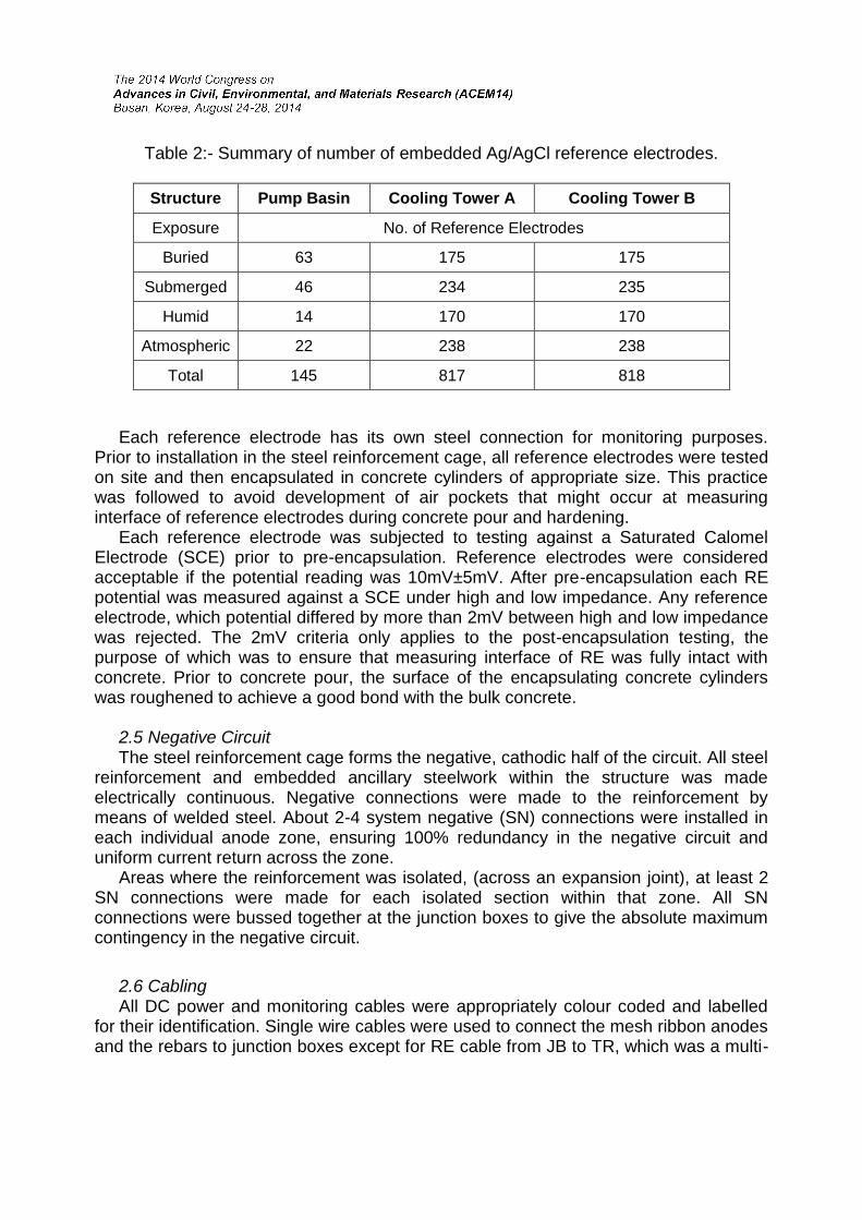
Table 2:- Summary of number of embedded Ag/AgCl reference electrodes.
Structure Pump Basin Cooling Tower A Cooling Tower B
Exposure No. of Reference Electrodes
Buried 63 175 175
Submerged 46 234 235
Humid 14 170 170
Atmospheric 22 238 238
Total 145 817 818
Each reference electrode has its own steel connection for monitoring purposes. Prior to installation in the steel reinforcement cage, all reference electrodes were tested on site and then encapsulated in concrete cylinders of appropriate size. This practice was followed to avoid development of air pockets that might occur at measuring interface of reference electrodes during concrete pour and hardening. Each reference electrode was subjected to testing against a Saturated Calomel Electrode (SCE) prior to pre-encapsulation. Reference electrodes were considered acceptable if the potential reading was 10mV±5mV. After pre-encapsulation each RE potential was measured against a SCE under high and low impedance. Any reference electrode, which potential differed by more than 2mV between high and low impedance was rejected. The 2mV criteria only applies to the post-encapsulation testing, the purpose of which was to ensure that measuring interface of RE was fully intact with concrete. Prior to concrete pour, the surface of the encapsulating concrete cylinders was roughened to achieve a good bond with the bulk concrete. 2.5 Negative Circuit The steel reinforcement cage forms the negative, cathodic half of the circuit. All steel reinforcement and embedded ancillary steelwork within the structure was made electrically continuous. Negative connections were made to the reinforcement by means of welded steel. About 2-4 system negative (SN) connections were installed in each individual anode zone, ensuring 100% redundancy in the negative circuit and uniform current return across the zone. Areas where the reinforcement was isolated, (across an expansion joint), at least 2 SN connections were made for each isolated section within that zone. All SN connections were bussed together at the junction boxes to give the absolute maximum contingency in the negative circuit.
2.6 Cabling All DC power and monitoring cables were appropriately colour coded and labelled for their identification. Single wire cables were used to connect the mesh ribbon anodes and the rebars to junction boxes except for RE cable from JB to TR, which was a multi-
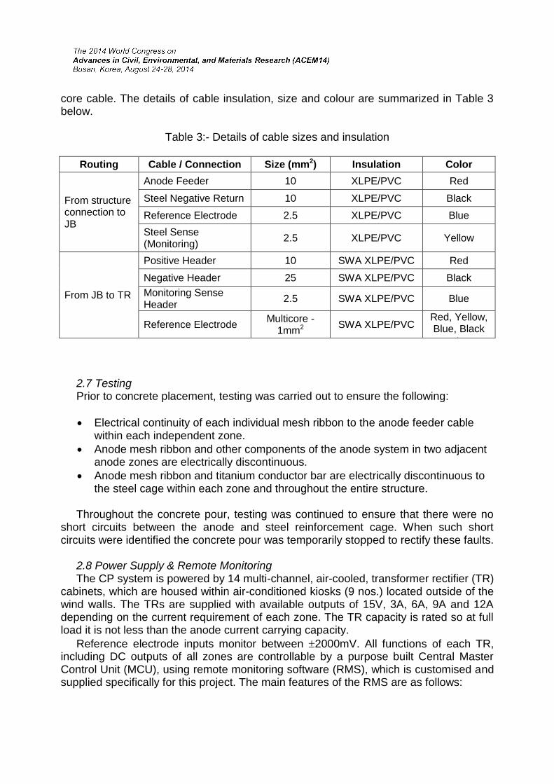
core cable. The details of cable insulation, size and colour are summarized in Table 3 below.
Table 3:- Details of cable sizes and insulation
Routing Cable / Connection Size (mm2) Insulation Color
From structure connection to JB
Anode Feeder 10 XLPE/PVC Red
Steel Negative Return 10 XLPE/PVC Black
Reference Electrode 2.5 XLPE/PVC Blue
Steel Sense (Monitoring)
2.5 XLPE/PVC Yellow
From JB to TR
Positive Header 10 SWA XLPE/PVC Red
Negative Header 25 SWA XLPE/PVC Black
Monitoring Sense Header
2.5 SWA XLPE/PVC Blue
Reference Electrode Multicore -
1mm2 SWA XLPE/PVC
Red, Yellow, Blue, Black
etc. 2.7 Testing Prior to concrete placement, testing was carried out to ensure the following:
Electrical continuity of each individual mesh ribbon to the anode feeder cable within each independent zone.
Anode mesh ribbon and other components of the anode system in two adjacent anode zones are electrically discontinuous.
Anode mesh ribbon and titanium conductor bar are electrically discontinuous to the steel cage within each zone and throughout the entire structure.
Throughout the concrete pour, testing was continued to ensure that there were no short circuits between the anode and steel reinforcement cage. When such short circuits were identified the concrete pour was temporarily stopped to rectify these faults. 2.8 Power Supply & Remote Monitoring The CP system is powered by 14 multi-channel, air-cooled, transformer rectifier (TR) cabinets, which are housed within air-conditioned kiosks (9 nos.) located outside of the wind walls. The TRs are supplied with available outputs of 15V, 3A, 6A, 9A and 12A depending on the current requirement of each zone. The TR capacity is rated so at full load it is not less than the anode current carrying capacity.
Reference electrode inputs monitor between 2000mV. All functions of each TR, including DC outputs of all zones are controllable by a purpose built Central Master Control Unit (MCU), using remote monitoring software (RMS), which is customised and supplied specifically for this project. The main features of the RMS are as follows:

Read and set operating parameters
Monitor each zone in real time
Daily Log of Current-On, & Instant-off steel potentials at set time intervals
Conduct global depolarization tests at set intervals
Retrieve & analyze depolarization data
Provide criteria compliance summary of all zones
DC output status screen
Alarm enabling
Set high/low limits 3. SYSTEM COMMISSIONING, MONITORING, & PERFORMANCE ASSESSMENT 3.1 Initial Energizing All zones of CT-A, CT-B (except zone 6A, & 9A), and Pump Basin (PB) were energized in June 2010. The systems were powered in constant current mode at an applied steel current density of 2.5mA/m2 (50% of design current density). Later on the current was increased, where required to achieve protection criteria. But due to some site obstructions, CT-B zones were turned off and then all zones of CT-B were re-energized in October 2010. Prior to initial energizing, natural potentials were measured (every 2-3 weeks after completion of concrete pour until initial energizing) and established at the location of all embedded reference electrodes in all zones. 3.2 System Monitoring & Assessment The following two criteria (European Standard BS EN ISO 12696) are used for assessing the effectiveness of the cathodic prevention systems of CTs & PB.
100 mV potential decay from instant-off in 24 hours after current interruption.
An instant-off potential more negative than –720 mV Ag/AgCl. The CT-A results (from latest monitoring) are summarized in Table 4 and Fig. 4 below.
Table 4:- Summary of criteria compliance for Cooling Tower A.
Exposure Zones Nos.
Applied Steel Current Density mA/m2
REs Nos.
CP System Criteria Compliance
Ranged Average RE (Nos.) RE (%)
Buried 25 3.7 to 6.0 5.0 175 128 73%
Submerged 27 2.5 to 6.0 5.3 234 202 86%
Humid 24 2.5 to 6.0 5.2 170 148 87%
Atmospheric 34 2.5 to 7.2 4.3 238 201 84%

Fig. 4: Summary of criteria compliance with time for CT-A.
The results show that 679 REs (83%) achieved the protection criteria, a further 110 REs (14%) achieved a depolarization between 99mV & 50mV and 28 REs (3%) achieved 49mV or below, out of the total of 817 REs. The global summary of results shown in Fig. 3 below indicates that criteria compliance improved with time. The applied steel current densities ranged between 2.5 and 7.5 mA/m2, whereas the average values were quite close to the design steel current density and ranged between 4.3 and 5 mA/m2. As the polarization growth is increasing gradually with time, it is expected that 100% criteria compliance would be achieved within a few months and this would then be followed by a gradual reduction in applied current levels. The CT-B results (from latest monitoring) are summarized in Table 5 and Fig. 5 below.
Table 5:- Summary of criteria compliance for Cooling Tower B.
Exposure Zones Nos.
Applied Steel Current Density mA/m2
REs Nos.
CP System Criteria Compliance
Range Average RE (Nos.) RE (%)
Buried 25 2.5 to 4.5 3.2 175 128 73%
Submerged 27 2.5 to 4.1 3.3 235 195 83%
Humid 24 2.5 to 5.0 4.2 170 112 66%
Atmospheric 34 2.5 to 5.0 3.4 238 159 67%
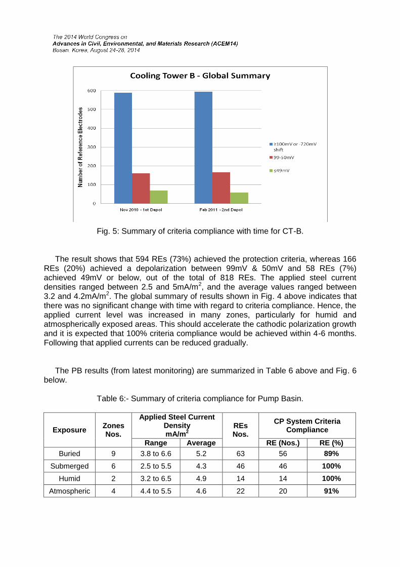
Fig. 5: Summary of criteria compliance with time for CT-B. The result shows that 594 REs (73%) achieved the protection criteria, whereas 166 REs (20%) achieved a depolarization between 99mV & 50mV and 58 REs (7%) achieved 49mV or below, out of the total of 818 REs. The applied steel current densities ranged between 2.5 and 5mA/m2, and the average values ranged between 3.2 and 4.2mA/m2. The global summary of results shown in Fig. 4 above indicates that there was no significant change with time with regard to criteria compliance. Hence, the applied current level was increased in many zones, particularly for humid and atmospherically exposed areas. This should accelerate the cathodic polarization growth and it is expected that 100% criteria compliance would be achieved within 4-6 months. Following that applied currents can be reduced gradually. The PB results (from latest monitoring) are summarized in Table 6 above and Fig. 6 below.
Table 6:- Summary of criteria compliance for Pump Basin.
Exposure Zones Nos.
Applied Steel Current Density mA/m2
REs Nos.
CP System Criteria Compliance
Range Average RE (Nos.) RE (%)
Buried 9 3.8 to 6.6 5.2 63 56 89%
Submerged 6 2.5 to 5.5 4.3 46 46 100%
Humid 2 3.2 to 6.5 4.9 14 14 100%
Atmospheric 4 4.4 to 5.5 4.6 22 20 91%

Fig. 6: Summary of criteria compliance with time for Pump Basin.
The results show that 136 REs (94%) achieved the protection criteria, whereas 7REs (5%) achieved a depolarization between 99mV & 50mV and 2 REs (1%) achieved 49mV or below, out of the total of 145 REs. The global summary of results shown in Fig. 8 above indicates that criteria compliance improved with time. The applied steel current densities ranged between 2.5 and 6.6 mA/m2, whereas the average values were quite close to the design steel current density and ranged between 4.3 and 5.2 mA/m2. As the polarization growth is increasing gradually with time, it is expected that 100% criteria compliance would be achieved within few months and following that applied currents can be reduced gradually. 4. Conclusions The cathodic prevention systems for 2 very large size cooling towers and a pump basin have been successfully installed and commissioned. The monitoring data gathered during the 6-9 months after the initial energizing of the CP systems have shown that the specified criteria have already been met at 1409 (79%) monitoring locations out of the total of 1780( for all 3 structures). At several locations where the criteria have not been achieved so far, the depolarization was recorded between 80mV and 99mV. The monitoring data trend has suggested that polarization growth in the negative direction is gradually increasing with time. This implies that the overall CP system is meeting its design objectives in preventing corrosion of the reinforcing steel in these seawater structures. Applied average steel current densities required to achieve adequate protection in different exposures of all 3 structures have ranged between 3.2 and 5.3 mA/m2 and

generally were very close the to the design current density (5 mA/m2). This shows that designing CP systems for seawater structures in very hot and humid environments using 5 mA/m2 steel current density would be a better and a safer approach than the rang recommended in the European Standard. As the polarization growth is increasing gradually with time, it is expected that 100% criteria compliance would be achieved within few months and then the required applied current levels could be reduced with time. The power supply and remote monitoring system that was specifically designed and customized for this project has proved to be not only a useful but an essential tool for monitoring, assessing and controlling such a huge CP system. Without this RMS, CP systems of this size and application cannot be monitored and assessed so effectively and accurately. REFERENCES Chaudhary Z, and Al-Muhid T, “Rehabilitation and Corrosion Control of Seawater
Concrete Structures in Petrochemical Plants” EUROCORR 2000, Institute of Corrosion, London, U.K. September 2000.
Chaudhary Z, “Design & Protection Criteria for Cathodic Protection of Seawater Intake Structures in Petrochemical plants” Marine Corrosion in Tropical Environments, ASTM STP 1399, S.W.Dean, J.B.Bushman Eds., American Society for Testing and Materials, West Conshohocken, PA, 2000, pp 218-230.
Bertolini L, Bolzoni F, Pastore T, & Pedeferri P, “ New Experiences on Cathodic Prevention of Reinforced Concrete Structures,” SCI Proc. Of 4th International Symposium on “ Corrosion of Reinforcement in Concrete Construction,” Eds Page C.L. , Bamforth P.B. and Figg J.W., p. 389, 1996.
European Standard BS EN ISO 12696, “Cathodic Protection of Steel in Concrete” 2012.
Chaudhary Zia, “Cathodic Prevention of New Seawater Concrete Structures in Petrochemical Plants” Paper no. 02260, NACE CORROSION 2002, Denver, Colorado, April 2002.
Chaudhary Zia, Fahad Mutlaq, F. Rodel “A Case History of Cathodic Prevention of Seawater Structures” Paper no. 06346, NACE CORROSION 2006, San Diego, California, March 2006.
Bromfield J.P, Corrosion of Steel in Concrete, (London, E & FN SPON, 1997), p 143. Chess P.M. , Cathodic Protection of Steel in Concrete, (London, E & FN SPON, 1998),
p 42.


![Performance and Durability Evaluation of Bamboo Reinforced ... · ... bamboo reinforced beam [4]. Bamboo reinforced concrete design is similar to steel reinforced concrete design](https://static.fdocuments.us/doc/165x107/5b573ef17f8b9adf7d8d8ed2/performance-and-durability-evaluation-of-bamboo-reinforced-bamboo-reinforced.jpg)