Enhancement of collection efficiency of inertial impactors using elliptical concave impaction plates
11
Enhancement of collection efficiency of inertial impactors using elliptical concave impaction plates Young-Jun Kim, Se-Jin Yook n School of Mechanical Engineering, Hanyang University, Seoul 133-791, Republic of Korea article info Article history: Received 3 May 2011 Received in revised form 6 July 2011 Accepted 26 August 2011 Available online 5 September 2011 Keywords: Inertial impactor Impaction plate Elliptical concave impaction plate Collection efficiency Stokes number abstract In this study, elliptical concave impaction plate was suggested for lowering cut-off size and therefore enhancing collection efficiency of the inertial impactor. Statistical Lagrangian Particle Tracking (SLPT) model was employed for calculating impactor collection efficiency and validated by comparing with the experimental data of Tsai, C.J., Cheng, Y.H. ((1995). Solid particle collection characteristics on impaction surfaces of different designs. Aerosol Science Technology, 23, 96–106), for three different shapes of impaction plates. Then, the effect of the ratio of major axis length (A) to minor axis length (B) for determining the curvature of elliptical concave impaction plate, on impactor collection efficiency was numerically investigated using the SLPT model, with nozzle Reynolds numbers ranging from 1440 to 2600. It was found that there existed an optimum range of the A/B ratio for minimizing the cut-off size, i.e. the A/B ratio ranged between 3.2 and 4.2 for the PM10 inertial impactor, or between 3.2 and 3.5 for the PM2.5 inertial impactor. When the elliptical concave impaction plates with the A/B ratio of 4.0 and 3.5 were applied to the MST indoor air sampling impactor having PM10 and PM2.5 stages, the cut-off size was predicted to decrease from 10 to 6.5 mm and from 2.5 to 1.6 mm, respectively, while the impactor collection efficiency curves became less steep. & 2011 Elsevier Ltd. All rights reserved. 1. Introduction Inertial impactors are widely used for sampling and analyzing indoor and outdoor aerosol particles (Gomes et al., 1990; Pastuszka et al., 2000; Ruuskanen et al., 2001; Braniˇ s et al, 2005; Park & Kim, 2006; Kam et al., 2011). When the aerosol is accelerated by a nozzle and impinged onto an impaction plate, airborne particles are separated from air stream and collected on the impaction plate according to particle inertia. Most of the particles larger than a certain size, i.e. cut-off size, are collected on the impaction plate while most of the particles smaller than the cut-off size are not sampled. The cut- off size of an inertial impactor can be affected by many factors such as aerosol flowrate, nozzle diameter, nozzle throat length, nozzle-to-plate distance, surface roughness and shape of impaction plate, etc. The theory of inertial impactors has been well established (Marple et al., 1974; Rader & Marple, 1985), and inertial impactors can be designed to have desirable cut-off sizes under various operating conditions. Substantial efforts have been made by many researchers to reduce the cut-off size, or increase the collection efficiency, of inertial impactors. Enhancement of collection efficiency could be achieved by making the ratio of nozzle-to-plate distance (S) to nozzle diameter (W) smaller than 1, i.e. S/Wo1(Grinshpun et al., 2005). Low pressure condition inside an inertial impactor was explored and found to be useful for lowering the cut-off size (Arffman et al., 2011). Thermophoresis Contents lists available at SciVerse ScienceDirect journal homepage: www.elsevier.com/locate/jaerosci Journal of Aerosol Science 0021-8502/$ - see front matter & 2011 Elsevier Ltd. All rights reserved. doi:10.1016/j.jaerosci.2011.08.006 n Corresponding author. Tel.: þ82 2 2220 0422; fax: þ82 2 2220 2299. E-mail address: [email protected] (S.-J. Yook). Journal of Aerosol Science 42 (2011) 898–908
-
Upload
young-jun-kim -
Category
Documents
-
view
212 -
download
0
Transcript of Enhancement of collection efficiency of inertial impactors using elliptical concave impaction plates
Contents lists available at SciVerse ScienceDirect
Journal of Aerosol Science
Journal of Aerosol Science 42 (2011) 898–908
0021-85
doi:10.1
n Corr
E-m
journal homepage: www.elsevier.com/locate/jaerosci
Enhancement of collection efficiency of inertial impactors usingelliptical concave impaction plates
Young-Jun Kim, Se-Jin Yook n
School of Mechanical Engineering, Hanyang University, Seoul 133-791, Republic of Korea
a r t i c l e i n f o
Article history:
Received 3 May 2011
Received in revised form
6 July 2011
Accepted 26 August 2011Available online 5 September 2011
Keywords:
Inertial impactor
Impaction plate
Elliptical concave impaction plate
Collection efficiency
Stokes number
02/$ - see front matter & 2011 Elsevier Ltd. A
016/j.jaerosci.2011.08.006
esponding author. Tel.: þ82 2 2220 0422; fa
ail address: [email protected] (S.-J. Yook
a b s t r a c t
In this study, elliptical concave impaction plate was suggested for lowering cut-off size
and therefore enhancing collection efficiency of the inertial impactor. Statistical
Lagrangian Particle Tracking (SLPT) model was employed for calculating impactor
collection efficiency and validated by comparing with the experimental data of Tsai, C.J.,
Cheng, Y.H. ((1995). Solid particle collection characteristics on impaction surfaces of
different designs. Aerosol Science Technology, 23, 96–106), for three different shapes of
impaction plates. Then, the effect of the ratio of major axis length (A) to minor axis
length (B) for determining the curvature of elliptical concave impaction plate, on
impactor collection efficiency was numerically investigated using the SLPT model, with
nozzle Reynolds numbers ranging from 1440 to 2600. It was found that there existed an
optimum range of the A/B ratio for minimizing the cut-off size, i.e. the A/B ratio ranged
between 3.2 and 4.2 for the PM10 inertial impactor, or between 3.2 and 3.5 for the PM2.5
inertial impactor. When the elliptical concave impaction plates with the A/B ratio of 4.0 and
3.5 were applied to the MST indoor air sampling impactor having PM10 and PM2.5 stages,
the cut-off size was predicted to decrease from 10 to 6.5 mm and from 2.5 to 1.6 mm,
respectively, while the impactor collection efficiency curves became less steep.
& 2011 Elsevier Ltd. All rights reserved.
1. Introduction
Inertial impactors are widely used for sampling and analyzing indoor and outdoor aerosol particles (Gomes et al., 1990;Pastuszka et al., 2000; Ruuskanen et al., 2001; Branis et al, 2005; Park & Kim, 2006; Kam et al., 2011). When the aerosol isaccelerated by a nozzle and impinged onto an impaction plate, airborne particles are separated from air stream andcollected on the impaction plate according to particle inertia. Most of the particles larger than a certain size, i.e. cut-offsize, are collected on the impaction plate while most of the particles smaller than the cut-off size are not sampled. The cut-off size of an inertial impactor can be affected by many factors such as aerosol flowrate, nozzle diameter, nozzle throatlength, nozzle-to-plate distance, surface roughness and shape of impaction plate, etc. The theory of inertial impactors hasbeen well established (Marple et al., 1974; Rader & Marple, 1985), and inertial impactors can be designed to have desirablecut-off sizes under various operating conditions.
Substantial efforts have been made by many researchers to reduce the cut-off size, or increase the collection efficiency,of inertial impactors. Enhancement of collection efficiency could be achieved by making the ratio of nozzle-to-platedistance (S) to nozzle diameter (W) smaller than 1, i.e. S/Wo1 (Grinshpun et al., 2005). Low pressure condition inside aninertial impactor was explored and found to be useful for lowering the cut-off size (Arffman et al., 2011). Thermophoresis
ll rights reserved.
x: þ82 2 2220 2299.
).
Y.-J. Kim, S.-J. Yook / Journal of Aerosol Science 42 (2011) 898–908 899
by cooling the impaction plate was helpful for sampling more particles on the impaction plate (Lee & Kim, 2002). When theaerosol particles are charged, electrophoresis could be applied to enhance the impactor collection efficiency (Vinchurkar et al.,2009). These methods, however, require modifying greatly the impactor geometries or introducing additional energy.
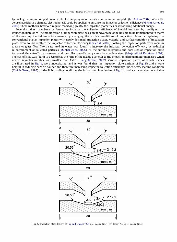
Several studies have been performed to increase the collection efficiency of inertial impactor by modifying theimpaction plate only. The modification of impaction plate has a great advantage of being able to be implemented to manyof the existing inertial impactors merely by changing the surface conditions of impaction plates or replacing theconventional planar impaction plates with newly designed impaction plates. Material and surface condition of impactionplates were found to affect the impactor collection efficiency (Lee et al., 2005). Coating the impaction plate with vacuumgrease or glass fiber filters saturated in water was found to increase the impactor collection efficiency by reducingre-entrainment of collected particles (Dunbar et al., 2005). As the surface roughness and pore size of impaction plateincreased, the cut-off size decreased and the collection efficiency curve became less steep (Marjamaki & Keskinen, 2004).The cut-off size was found to decrease as the ratio of the nozzle diameter to the impaction plate diameter increased whennozzle Reynolds number was smaller than 1500 (Huang & Tsai, 2002). Various impaction plates, of which shapesare illustrated in Fig. 1, were investigated, and it was found that the impaction plate designs of Fig. 1b and c werehelpful in reducing particle bounce and therefore increasing impactor collection efficiency under heavy loading condition(Tsai & Cheng, 1995). Under light loading condition, the impaction plate design of Fig. 1c produced a smaller cut-off size
Fig. 1. Impaction plate designs of Tsai and Cheng (1995): (a) design No. 1; (b) design No. 2; (c) design No. 3.
Y.-J. Kim, S.-J. Yook / Journal of Aerosol Science 42 (2011) 898–908900
than that of Fig. 1a, while the design of Fig. 1b showed a larger cut-off size than that of Fig. 1a, which implies that anoptimum design of impaction plate may exist to make the cut-off size as small as possible under a fixed operatingcondition.
In this study, an elliptical concave impaction plate is considered as a substitute for the conventional flat impaction platein an effort to decrease the cut-off size of inertial impactors. A numerical model is developed to calculate the impactorcollection efficiency according to particle size and validated by comparing the present numerical collection efficiencieswith the experimental results of Tsai & Cheng (1995). Then, the numerical model is employed to investigate the collectionefficiencies of inertial impactors with elliptical concave impaction plates. The ratio of major axis length to minor axislength of the elliptical concave impaction plate is varied and a guideline to minimize cut-off size is suggested.
2. Statistical Lagrangian particle tracking (SLPT) model
2.1. Calculation of flow field
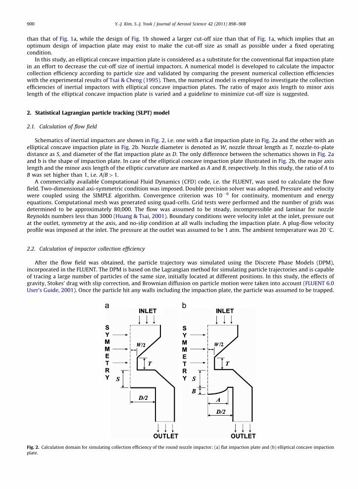
Schematics of inertial impactors are shown in Fig. 2, i.e. one with a flat impaction plate in Fig. 2a and the other with anelliptical concave impaction plate in Fig. 2b. Nozzle diameter is denoted as W, nozzle throat length as T, nozzle-to-platedistance as S, and diameter of the flat impaction plate as D. The only difference between the schematics shown in Fig. 2aand b is the shape of impaction plate. In case of the elliptical concave impaction plate illustrated in Fig. 2b, the major axislength and the minor axis length of the elliptic curvature are marked as A and B, respectively. In this study, the ratio of A toB was set higher than 1, i.e. A/B41.
A commercially available Computational Fluid Dynamics (CFD) code, i.e. the FLUENT, was used to calculate the flowfield. Two-dimensional axi-symmetric condition was imposed. Double precision solver was adopted. Pressure and velocitywere coupled using the SIMPLE algorithm. Convergence criterion was 10�6 for continuity, momentum and energyequations. Computational mesh was generated using quad-cells. Grid tests were performed and the number of grids wasdetermined to be approximately 80,000. The flow was assumed to be steady, incompressible and laminar for nozzleReynolds numbers less than 3000 (Huang & Tsai, 2001). Boundary conditions were velocity inlet at the inlet, pressure outat the outlet, symmetry at the axis, and no-slip condition at all walls including the impaction plate. A plug-flow velocityprofile was imposed at the inlet. The pressure at the outlet was assumed to be 1 atm. The ambient temperature was 20 1C.
2.2. Calculation of impactor collection efficiency
After the flow field was obtained, the particle trajectory was simulated using the Discrete Phase Models (DPM),incorporated in the FLUENT. The DPM is based on the Lagrangian method for simulating particle trajectories and is capableof tracing a large number of particles of the same size, initially located at different positions. In this study, the effects ofgravity, Stokes’ drag with slip correction, and Brownian diffusion on particle motion were taken into account (FLUENT 6.0User’s Guide, 2001). Once the particle hit any walls including the impaction plate, the particle was assumed to be trapped.
Fig. 2. Calculation domain for simulating collection efficiency of the round nozzle impactor: (a) flat impaction plate and (b) elliptical concave impaction
plate.
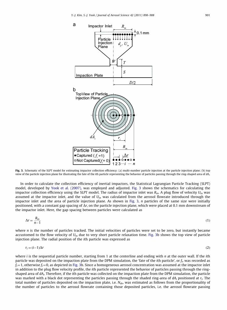
Fig. 3. Schematic of the SLPT model for estimating impactor collection efficiency: (a) multi-number particle injection at the particle injection plane; (b) top
view of the particle injection plane for illustrating the fate of the ith particle representing the behavior of particles passing through the ring-shaped area of dAi.
Y.-J. Kim, S.-J. Yook / Journal of Aerosol Science 42 (2011) 898–908 901
In order to calculate the collection efficiency of inertial impactors, the Statistical Lagrangian Particle Tracking (SLPT)model, developed by Yook et al. (2007), was employed and adjusted. Fig. 3 shows the schematics for calculating theimpactor collection efficiency using the SLPT model. The radius of impactor inlet was Rin. A plug flow of velocity Uin wasassumed at the impactor inlet, and the value of Uin was calculated from the aerosol flowrate introduced through theimpactor inlet and the area of particle injection plane. As shown in Fig. 3, n particles of the same size were initiallypositioned, with a constant gap spacing of Dr, on the particle injection plane, which were placed at 0.1 mm downstream ofthe impactor inlet. Here, the gap spacing between particles were calculated as
Dr¼Rin
n�1ð1Þ
where n is the number of particles tracked. The initial velocities of particles were set to be zero, but instantly becameaccustomed to the flow velocity of Uin due to very short particle relaxation time. Fig. 3b shows the top view of particleinjection plane. The radial position of the ith particle was expressed as
ri ¼ ði�1ÞDr ð2Þ
where i is the sequential particle number, starting from 1 at the centerline and ending with n at the outer wall. If the ithparticle was deposited on the impaction plate from the DPM simulation, the ‘fate of the ith particle’, or fi, was recorded asfi¼1, otherwise fi¼0, as depicted in Fig. 3b. Since a homogeneous aerosol concentration was assumed at the impactor inletin addition to the plug flow velocity profile, the ith particle represented the behavior of particles passing through the ring-shaped area of dAi. Therefore, if the ith particle was collected on the impaction plate from the DPM simulation, the particlewas marked with a black dot representing the particles passing through the shaded ring-area of dAi positioned at ri. Thetotal number of particles deposited on the impaction plate, i.e. Nde, was estimated as follows from the proportionality ofthe number of particles to the aerosol flowrate containing those deposited particles, i.e. the aerosol flowrate passing

Y.-J. Kim, S.-J. Yook / Journal of Aerosol Science 42 (2011) 898–908902
through the shaded ring-areas (Qshade). Namely
NdepQshade ¼
ZfidQi ¼
ZfiUindAi ¼ 2pUin
Z Rin
r ¼ 0firidr � 2pUinDr
Xn
i ¼ 1
firi ð3Þ
The total number of particles injected through the particle injection plane, i.e. Nin, was assumed to be proportional tothe aerosol flowrate (Qa) introduced through the particle injection plane. Or
NinpQa ¼ pR2inUin ð4Þ
Finally, the impactor collection efficiency, i.e. Z, was obtained as
Z¼ Nde
Nin¼
2Dr
R2in
Xn
i ¼ 1
firi ð5Þ
2.3. Model validation
The numerical model described above was validated by comparing the numerically obtained impactor collectionefficiencies with the experimental data of Tsai & Cheng (1995) for the impaction plate designs shown in Fig. 1. The nozzlediameter was W¼2.4 mm and the aerosol flowrate through the nozzle was Qa¼5 L/min, aiming at the cut-off size (dp50) of2 mm. The nozzle Reynolds number was about 2900. Thus, the flow was assumed to be laminar. The nozzle throat length
Fig. 4. Comparison of impactor collection efficiency between the present model and the experimental data of Tsai and Cheng (1995), according to the
shape of impaction plate: (a) design No. 1; (b) design No. 2 and (c) design No. 3.
Y.-J. Kim, S.-J. Yook / Journal of Aerosol Science 42 (2011) 898–908 903
was T¼2.4 mm. The nozzle-to-plate distance was S¼2.4 mm. The flat impaction plate diameter, which was not clearlystated in Tsai & Cheng (1995), was assumed to be D¼30 mm as conjectured from their schematics. Ammonium fluoresceinparticles (particle density of rp¼1.35 g/cm3) were assumed, as used by Tsai & Cheng (1995) for their experiments. For theSLPT model calculation, the number of particles tracked was determined to be n¼500.
Fig. 4 compares the impactor collection efficiencies between the present numerical model and the experimental data ofTsai & Cheng (1995) according to impaction plate design. Here, the Stokes number giving 50% of impactor collectionefficiency, i.e. Stk50, was defined as
Stk50 ¼rpd2
p50CcUW
9mWð6Þ
where Cc is the slip correction factor, UW is the mean aerosol flow velocity through the nozzle with diameter of W, and m isthe viscosity of air. In the experiments of Tsai & Cheng (1995), the impaction plates were coated with a thin layer of siliconoil spray. The particle bounce problem was not shown in case of the light loading tests, but was intensified for particlesgreater than the cut-off sizes in case of the heavy loading tests. The discrepancies between the numerical data and theexperimental results of heavy loading tests, for particles larger than the cut-off sizes, were due to the fact that the particlebounce was not considered in the numerical simulation. From the results of the present numerical model, the collectionefficiency curves looked S-shaped and the cut-off sizes were estimated to be dp50¼1.9 mm for Design No. 1, dp50¼2.0 mmfor Design No. 2, and dp50¼1.7 mm for Design No. 3, which supported the present study’s hypothesis of the existence of theoptimum shape of impaction plate for decreasing cut-off size. As compared in Fig. 4, the numerically estimated cut-offsizes were very close to the experimental data of Tsai & Cheng (1995). In addition, the collection efficiencies of particlessmaller than the cut-off sizes were in good agreement with either light loading test or heavy loading test results. Thepresent numerical model, therefore, was verified to produce correct results.
3. Results and discussion
3.1. Collection efficiency according to impaction plate shape
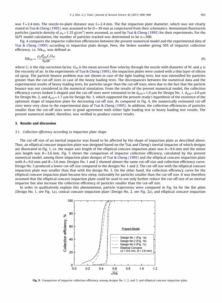
The cut-off size of an inertial impactor was found to be affected by the shape of impaction plate as described above.Thus, an elliptical concave impaction plate was designed based on the Tsai and Cheng’s inertial impactor of which designsare illustrated in Fig. 1, i.e. the major axis length of the elliptical concave impaction plate was A¼9.6 mm and the minoraxis length was B¼3.6 mm. Fig. 5 shows the comparison of impactor collection efficiency, calculated by the presentnumerical model, among three impaction plate designs of Tsai & Cheng (1995) and the elliptical concave impaction platewith A¼9.6 mm and B¼3.6 mm. Designs No. 1 and 2 showed almost the same cut-off size and collection efficiency curve.Design No. 3 produced a lower cut-off size compared to the designs No. 1 and 2. The cut-off size with the elliptical concaveimpaction plate was smaller than that with the design No. 3. On the other hand, the collection efficiency curve for theelliptical concave impaction plate became less steep, noticeably for particles smaller than the cut-off size. It was thereforeassumed that the elliptical concave impaction plate could be used to not only further reduce the cut-off size of an inertialimpactor but also increase the collection efficiency of particles smaller than the cut-off size.
In order to qualitatively explain this phenomenon, particle trajectories were compared in Fig. 6a for the flat plate(Design No. 1, see Fig. 1a), conical concave impaction plate (Design No. 2, see Fig. 2a), and elliptical concave impaction
Fig. 5. Comparison of impactor collection efficiency among designs No. 1, 2, and 3, and elliptical concave impaction plate.
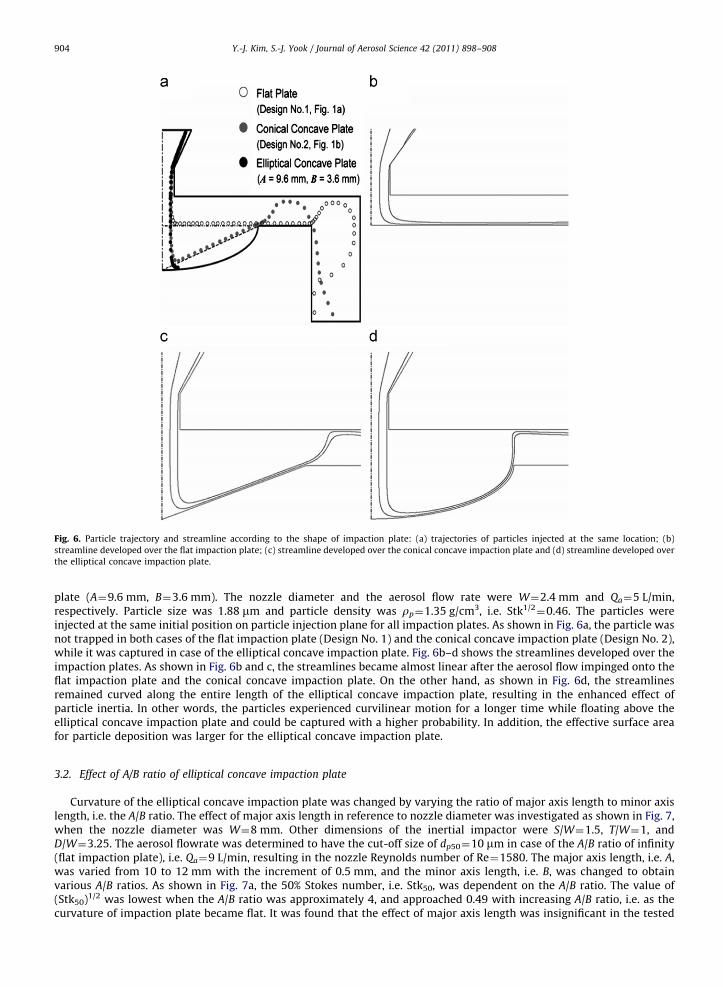
Fig. 6. Particle trajectory and streamline according to the shape of impaction plate: (a) trajectories of particles injected at the same location; (b)
streamline developed over the flat impaction plate; (c) streamline developed over the conical concave impaction plate and (d) streamline developed over
the elliptical concave impaction plate.
Y.-J. Kim, S.-J. Yook / Journal of Aerosol Science 42 (2011) 898–908904
plate (A¼9.6 mm, B¼3.6 mm). The nozzle diameter and the aerosol flow rate were W¼2.4 mm and Qa¼5 L/min,respectively. Particle size was 1.88 mm and particle density was rp¼1.35 g/cm3, i.e. Stk1/2
¼0.46. The particles wereinjected at the same initial position on particle injection plane for all impaction plates. As shown in Fig. 6a, the particle wasnot trapped in both cases of the flat impaction plate (Design No. 1) and the conical concave impaction plate (Design No. 2),while it was captured in case of the elliptical concave impaction plate. Fig. 6b–d shows the streamlines developed over theimpaction plates. As shown in Fig. 6b and c, the streamlines became almost linear after the aerosol flow impinged onto theflat impaction plate and the conical concave impaction plate. On the other hand, as shown in Fig. 6d, the streamlinesremained curved along the entire length of the elliptical concave impaction plate, resulting in the enhanced effect ofparticle inertia. In other words, the particles experienced curvilinear motion for a longer time while floating above theelliptical concave impaction plate and could be captured with a higher probability. In addition, the effective surface areafor particle deposition was larger for the elliptical concave impaction plate.
3.2. Effect of A/B ratio of elliptical concave impaction plate
Curvature of the elliptical concave impaction plate was changed by varying the ratio of major axis length to minor axislength, i.e. the A/B ratio. The effect of major axis length in reference to nozzle diameter was investigated as shown in Fig. 7,when the nozzle diameter was W¼8 mm. Other dimensions of the inertial impactor were S/W¼1.5, T/W¼1, andD/W¼3.25. The aerosol flowrate was determined to have the cut-off size of dp50¼10 mm in case of the A/B ratio of infinity(flat impaction plate), i.e. Qa¼9 L/min, resulting in the nozzle Reynolds number of Re¼1580. The major axis length, i.e. A,was varied from 10 to 12 mm with the increment of 0.5 mm, and the minor axis length, i.e. B, was changed to obtainvarious A/B ratios. As shown in Fig. 7a, the 50% Stokes number, i.e. Stk50, was dependent on the A/B ratio. The value of(Stk50)1/2 was lowest when the A/B ratio was approximately 4, and approached 0.49 with increasing A/B ratio, i.e. as thecurvature of impaction plate became flat. It was found that the effect of major axis length was insignificant in the tested
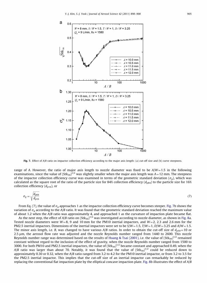
Fig. 7. Effect of A/B ratio on impactor collection efficiency according to the major axis length: (a) cut-off size and (b) curve steepness.
Y.-J. Kim, S.-J. Yook / Journal of Aerosol Science 42 (2011) 898–908 905
range of A. However, the ratio of major axis length to nozzle diameter was fixed to be A/W¼1.5 in the followingexaminations, since the value of (Stk50)1/2 was slightly smaller when the major axis length was A¼12 mm. The steepnessof the impactor collection efficiency curve was examined in terms of the geometric standard deviation (sg), which wascalculated as the square root of the ratio of the particle size for 84% collection efficiency (dp84) to the particle size for 16%collection efficiency (dp16), or
sg ¼
ffiffiffiffiffiffiffiffiffidp84
dp16
sð7Þ
From Eq. (7), the value of sg approaches 1 as the impactor collection efficiency curve becomes steeper. Fig. 7b shows thevariation of sg according to the A/B ratio. It was found that the geometric standard deviation reached the maximum valueof about 1.2 when the A/B ratio was approximately 4, and approached 1 as the curvature of impaction plate became flat.
As the next step, the effect of A/B ratio on (Stk50)1/2 was investigated according to nozzle diameter, as shown in Fig. 8a.Tested nozzle diameters were W¼8, 9 and 10 mm for the PM10 inertial impactors, and W¼2, 2.3 and 2.6 mm for thePM2.5 inertial impactors. Dimensions of the inertial impactors were set to be S/W¼1.5, T/W¼1, D/W¼3.25 and A/W¼1.5.The minor axis length, i.e. B, was changed to have various A/B ratios. In order to obtain the cut-off size of dp50¼10 or2.5 mm, the aerosol flow rate was adjusted and the nozzle Reynolds number ranged from 1440 to 2600. This nozzleReynolds number range was determined based on the results of Huang & Tsai (2001), i.e. the value of (Stk50)1/2 remainedconstant without regard to the inclusion of the effect of gravity, when the nozzle Reynolds number ranged from 1500 to3000. For both PM10 and PM2.5 inertial impactors, the value of (Stk50)1/2 became constant and approached 0.49, when theA/B ratio was larger than about 70. Notably, it was found that the value of (Stk50)1/2 could be reduced down toapproximately 0.30 or 0.32, when the A/B ratio ranged from 3.2 to 4.2 for the PM10 inertial impactor, or from 3.2 to 3.5 forthe PM2.5 inertial impactor. This implies that the cut-off size of an inertial impactor can remarkably be reduced byreplacing the conventional flat impaction plate by the elliptical concave impaction plate. Fig. 8b illustrates the effect of A/B
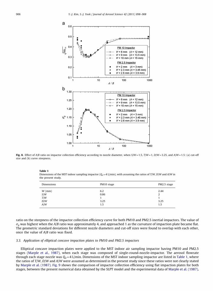
Fig. 8. Effect of A/B ratio on impactor collection efficiency according to nozzle diameter, when S/W¼1.5, T/W¼1, D/W¼3.25, and A/W¼1.5: (a) cut-off
size and (b) curve steepness.
Table 1Dimensions of the MST indoor sampling impactor (Qa¼4 L/min), with assuming the ratios of T/W, D/W and A/W in
the present study.
Dimensions PM10 stage PM2.5 stage
W (mm) 6.2 2.44
S/W 0.86 2
T/W 1 1
D/W 3.25 3.25
A/W 1.5 1.5
Y.-J. Kim, S.-J. Yook / Journal of Aerosol Science 42 (2011) 898–908906
ratio on the steepness of the impactor collection efficiency curve for both PM10 and PM2.5 inertial impactors. The value ofsg was highest when the A/B ratio was approximately 4, and approached 1 as the curvature of impaction plate became flat.The geometric standard deviations for different nozzle diameters and cut-off sizes were found to overlap with each other,once the value of A/B ratio was fixed.
3.3. Application of elliptical concave impaction plates to PM10 and PM2.5 impactors
Elliptical concave impaction plates were applied to the MST indoor air sampling impactor having PM10 and PM2.5stages (Marple et al., 1987), when each stage was composed of single-round-nozzle-impactor. The aerosol flowratethrough each stage nozzle was Qa¼4 L/min. Dimensions of the MST indoor sampling impactor are listed in Table 1, wherethe ratios of T/W, D/W and A/W were assumed as determined in the present study since these ratios were not clearly statedby Marple et al. (1987). Fig. 9 shows the comparison of impactor collection efficiency using flat impaction plates for bothstages, between the present numerical data obtained by the SLPT model and the experimental data of Marple et al. (1987),
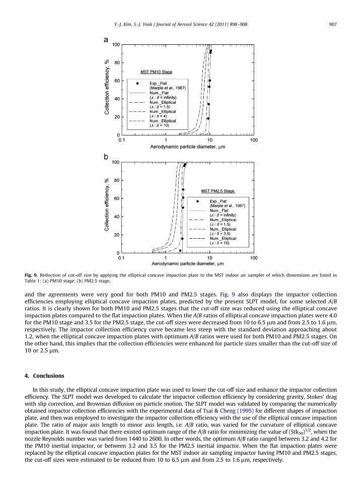
Fig. 9. Reduction of cut-off size by applying the elliptical concave impaction plate to the MST indoor air sampler of which dimensions are listed in
Table 1: (a) PM10 stage; (b) PM2.5 stage.
Y.-J. Kim, S.-J. Yook / Journal of Aerosol Science 42 (2011) 898–908 907
and the agreements were very good for both PM10 and PM2.5 stages. Fig. 9 also displays the impactor collectionefficiencies employing elliptical concave impaction plates, predicted by the present SLPT model, for some selected A/Bratios. It is clearly shown for both PM10 and PM2.5 stages that the cut-off size was reduced using the elliptical concaveimpaction plates compared to the flat impaction plates. When the A/B ratios of elliptical concave impaction plates were 4.0for the PM10 stage and 3.5 for the PM2.5 stage, the cut-off sizes were decreased from 10 to 6.5 mm and from 2.5 to 1.6 mm,respectively. The impactor collection efficiency curve became less steep with the standard deviation approaching about1.2, when the elliptical concave impaction plates with optimum A/B ratios were used for both PM10 and PM2.5 stages. Onthe other hand, this implies that the collection efficiencies were enhanced for particle sizes smaller than the cut-off size of10 or 2.5 mm.
4. Conclusions
In this study, the elliptical concave impaction plate was used to lower the cut-off size and enhance the impactor collectionefficiency. The SLPT model was developed to calculate the impactor collection efficiency by considering gravity, Stokes’ dragwith slip correction, and Brownian diffusion on particle motion. The SLPT model was validated by comparing the numericallyobtained impactor collection efficiencies with the experimental data of Tsai & Cheng (1995) for different shapes of impactionplate, and then was employed to investigate the impactor collection efficiency with the use of the elliptical concave impactionplate. The ratio of major axis length to minor axis length, i.e. A/B ratio, was varied for the curvature of elliptical concaveimpaction plate. It was found that there existed optimum range of the A/B ratio for minimizing the value of (Stk50)1/2, when thenozzle Reynolds number was varied from 1440 to 2600. In other words, the optimum A/B ratio ranged between 3.2 and 4.2 forthe PM10 inertial impactor, or between 3.2 and 3.5 for the PM2.5 inertial impactor. When the flat impaction plates werereplaced by the elliptical concave impaction plates for the MST indoor air sampling impactor having PM10 and PM2.5 stages,the cut-off sizes were estimated to be reduced from 10 to 6.5 mm and from 2.5 to 1.6 mm, respectively.

Y.-J. Kim, S.-J. Yook / Journal of Aerosol Science 42 (2011) 898–908908
References
Arffman, A., Marjamaki, M., & Keskinen, J. (2011). Simulation of low pressure impactor collection efficiency curves. Journal of Aerosol Science, 42, 329–340.Branis, M., Rezacova, P., & Domasova, M. (2005). The effect of outdoor air and indoor human activity on mass concentrations of PM10, PM2.5, and PM1 in a
classroom. Environmental Research, 99, 143–149.Dunbar, C., Kataya, A., & Tiangbe, T. (2005). Reducing bounce effects in the Andersen cascade impactor. International Journal of Pharmaceutics, 301, 25–32.FLUENT 6.0 User’s Guide, T. (2001). Dicrete Phase Models. FLUENT, INC.Gomes, L., Bergametti, G., Dulac, F., & Ezat, U. (1990). Assessing the actual size distribution of atmospheric aerosol collected with a cascade impactor.
Journal of Aerosol Science, 21, 47–59.Grinshpun, S.A., Mainelis, G., Trunov, M., Gorny, R.L., Sivasubramani, S.K., Adhikari, A., & Reponen, T. (2005). Collection of airborne spores by circular
single-stage impactors with small jet-to-plate distance. Journal of Aerosol Science, 36, 575–591.Huang, C.H., & Tsai, C.J. (2001). Effect of gravity on particle collection efficiency of inertial impactors. Journal of Aerosol Science, 32, 375–387.Huang, C.H., & Tsai, C.J. (2002). Influence of impaction plate diameter and particle density on the collection efficiency of round-nozzle inertial impactors.
Aerosol Science Technology, 36, 714–720.Kam, W., Cheung, K., Daher, N., & Sioutas, C. (2011). Particulate matter (PM) concentrations in underground and ground-level rail systems of the Los
Angeles Metro. Atmospheric Environment, 45, 1506–1516.Lee, B.U., & Kim, S.S. (2002). The effect of varying impaction plate temperature on impactor performance: experimental studies. Journal of Aerosol Science,
33, 451–457.Lee, S.J., Demokritou, P., & Koutrakis, P. (2005). Performance evaluation of commonly used impaction substrates under various loading conditions. Journal
of Aerosol Science, 36, 881–895.Marjamaki, M., & Keskinen, J. (2004). Effect of impaction plate roughness and porosity on collection efficiency. Journal of Aerosol Science, 35, 301–308.Marple, V.A., Liu, B.Y.H., & Whitby, K.T. (1974). Fluid mechanics of the laminar flow aerosol impactor. Journal of Aerosol Science, 5, 1–4.Marple, V.A., Rubow, K.L., Turner, W., & Spengler, J.D. (1987). Low flow rate sharp cut impactors for indoor air sampling: design and calibration. Journal of
the Air Pollution Control Association, 37, 1303–1307.Park, S.U., & Kim, J.W. (2006). Aerosol size distributions observed at the Seoul National University campus in Korea during the Asian dust and non-Asian
dust periods. Atmospheric Environment, 40, 1722–1730.Pastuszka, J.S., Kyaw Tha Paw, U., Lis, D.O., Wlaz"o, A., & Ulfig, K. (2000). Bacterial and fungal aerosol in indoor environment in Upper Silesia, Poland.
Atmospheric Environment, 34, 3833–3842.Rader, D.J., & Marple, V.A. (1985). Effect of ultra-stokesian drag and particle interception on impaction characteristics. Aerosol Science Technology, 4,
141–156.Ruuskanen, J., Tuch, Th., Ten Brink, H., Peters, A., Khlystov, A., Mirme, A., Kos, G.P.A., Brunekreef, B., Wichmann, H.E., Buzorius, G., Vallius, M., Kreyling,
W.G., & Pekkanen, J. (2001). Concentrations of ultrafine, fine and PM2.5 particles in three European cities. Atmospheric Environment, 35, 3729–3738.Tsai, C.J., & Cheng, Y.H. (1995). Solid particle collection characteristics on impaction surfaces of different designs. Aerosol Science Technology, 23, 96–106.Vinchurkar, S., Worth Longest, P., & Peart, J. (2009). CFD simulations of the Andersen cascade impactor: model development and effects of aerosol charge.
Journal of Aerosol Science, 40, 807–822.Yook, S.J., Fissan, H., Asbach, C., Kim, J.H., Wang, J., Yan, P.Y., & Pui, D.Y.H. (2007). Evaluation of protection schemes for ultraviolet lithography (EUVL)
masks against top-down aerosol flow. Journal of Aerosol Science, 38, 211–227.