Enhancement LTE System Based on DWT and Four STBC...
11
American Journal of Networks and Communications 2015; 4(2): 10-20 Published online March 14, 2015 (http://www.sciencepublishinggroup.com/j/ajnc) doi: 10.11648/j.ajnc.20150402.11 ISSN: 2326-893X (Print); ISSN: 2326-8964 (Online) Enhancement LTE System Based on DWT and Four STBC Transmit Antennas in Multichannel Models Laith Ali Abdul-Rahaim Electrical Engineering Department, Babylon University, Babil, Iraq Email address: [email protected] To cite this article: Laith Ali Abdul-Rahaim. Enhancement LTE System Based on DWT and Four STBC Transmit Antennas in Multichannel Models. American Journal of Networks and Communications. Vol. 4, No. 2, 2015, pp. 10-20. doi: 10.11648/j.ajnc.20150402.11 Abstract: In this paper Enhancement detail for the two main applications of Long Term Evolution (LTE) these are fixed and Mobile LTE. Fixed LTE will send the data from a single point-to-multipoint like user's houses and companies. While full mobility achieved by Mobile LTE to cellular networks. This done at very high broadband data rate comparted with other broadband networks like WiMax and Wi-Fi. The two types of LTE above are used in planning of a proper network which offers better throughput wireless broadband connectivity with lower cost. This work present a new proposed structures for LTE based on Space Time Block Coding (STBC-LTE) and Discrete Wavelets Transform (DWT) as multicarrier. The purpose of these new proposed structures is to improve the performance of bit error rate (BER) compared with the conventional STBC-LTE that use fast Fourier transform (FFT) as multicarrier. In addition, the new proposed structures with more than three transmits antennas and DWT was used in first time in LTE systems to enhance spectral efficiency and supports BER performance. The proposed STBC- LTE systems have been examined under different channel models like “AWGN, flat fading, and three types of multipath selective fading channel models (Extended Pedestrian, Extended Vehicular and Extended Typical Urban)”. The simulation results achieved in this work show that STBC- LTE based on DWT with four transmits antennas given best between other conventional STBC-LTE based on FFT systems. All these LTE systems models were built using MATLAB 2014a to permit various system parameters to be changed and tested like signal to noise ratio (SNR) and maximum Doppler shift and type of channel and channel parameters of the system. Keywords: LTE, Multipath Fading Channels, DWT, STBC, OFDM 1. Introduction With the Large increase of wireless networks and multimedia applications such as audio streaming, mobile TV, interactive gaming, video and Internet browsing, the mobile communication technology needs to meet different requirements of mobile data, mobile calculations and mobile multimedia operations. In order to prepare this increasing in mobile data usage and the new applications of multimedia, LTE and (LTE-A advance) technologies have been specified by the 3GPP as the emerging technologies of mobile communication for the next generation wireless broadband mobile networks. The LTE system is designed to be a packet-based system containing less network elements, which improves the system capacity and coverage, and provides high performance in terms of high data rates, low access latency, flexible bandwidth operation and seamless integration with other existing wireless communication systems [1]. The LTE-A system specified by the 3GPP LTE Release 10 enhances the existing LTE systems to support much higher data usage, lower latencies and better spectral efficiency [2]. In addition, both of the LTE and LTEA systems support “flat IP connectivity, full interworking with heterogeneous wireless access networks and many new types of base stations such as pico/femto base stations and relay nodes in a macro-cellular network”. Due to the introduction of the new characteristics, it incurs a lot of new challenges in security issue with the design architectures of the LTE and LTE-A systems. The Long-Term Evolution LTE is the newest expansion in the systems of 3GPP [3,4]. In 2004, the beginning of the first study in LTE systems, at this time the LTE was refers to the prospect evolution of UMTS. However, the word “LTE” bewitched many researchers, and so it became the favorite
Transcript of Enhancement LTE System Based on DWT and Four STBC...
American Journal of Networks and Communications 2015; 4(2): 10-20
Published online March 14, 2015 (http://www.sciencepublishinggroup.com/j/ajnc)
doi: 10.11648/j.ajnc.20150402.11
ISSN: 2326-893X (Print); ISSN: 2326-8964 (Online)
Enhancement LTE System Based on DWT and Four STBC Transmit Antennas in Multichannel Models
Laith Ali Abdul-Rahaim
Electrical Engineering Department, Babylon University, Babil, Iraq
Email address: [email protected]
To cite this article: Laith Ali Abdul-Rahaim. Enhancement LTE System Based on DWT and Four STBC Transmit Antennas in Multichannel Models. American
Journal of Networks and Communications. Vol. 4, No. 2, 2015, pp. 10-20. doi: 10.11648/j.ajnc.20150402.11
Abstract: In this paper Enhancement detail for the two main applications of Long Term Evolution (LTE) these are fixed and
Mobile LTE. Fixed LTE will send the data from a single point-to-multipoint like user's houses and companies. While full
mobility achieved by Mobile LTE to cellular networks. This done at very high broadband data rate comparted with other
broadband networks like WiMax and Wi-Fi. The two types of LTE above are used in planning of a proper network which offers
better throughput wireless broadband connectivity with lower cost. This work present a new proposed structures for LTE based
on Space Time Block Coding (STBC-LTE) and Discrete Wavelets Transform (DWT) as multicarrier. The purpose of these new
proposed structures is to improve the performance of bit error rate (BER) compared with the conventional STBC-LTE that use
fast Fourier transform (FFT) as multicarrier. In addition, the new proposed structures with more than three transmits antennas
and DWT was used in first time in LTE systems to enhance spectral efficiency and supports BER performance. The proposed
STBC- LTE systems have been examined under different channel models like “AWGN, flat fading, and three types of
multipath selective fading channel models (Extended Pedestrian, Extended Vehicular and Extended Typical Urban)”. The
simulation results achieved in this work show that STBC- LTE based on DWT with four transmits antennas given best between
other conventional STBC-LTE based on FFT systems. All these LTE systems models were built using MATLAB 2014a to
permit various system parameters to be changed and tested like signal to noise ratio (SNR) and maximum Doppler shift and
type of channel and channel parameters of the system.
Keywords: LTE, Multipath Fading Channels, DWT, STBC, OFDM
1. Introduction
With the Large increase of wireless networks and
multimedia applications such as audio streaming, mobile TV,
interactive gaming, video and Internet browsing, the mobile
communication technology needs to meet different
requirements of mobile data, mobile calculations and mobile
multimedia operations. In order to prepare this increasing in
mobile data usage and the new applications of multimedia,
LTE and (LTE-A advance) technologies have been specified
by the 3GPP as the emerging technologies of mobile
communication for the next generation wireless broadband
mobile networks.
The LTE system is designed to be a packet-based system
containing less network elements, which improves the system
capacity and coverage, and provides high performance in
terms of high data rates, low access latency, flexible
bandwidth operation and seamless integration with other
existing wireless communication systems [1]. The LTE-A
system specified by the 3GPP LTE Release 10 enhances the
existing LTE systems to support much higher data usage,
lower latencies and better spectral efficiency [2]. In addition,
both of the LTE and LTEA systems support “flat IP
connectivity, full interworking with heterogeneous wireless
access networks and many new types of base stations such as
pico/femto base stations and relay nodes in a macro-cellular
network”. Due to the introduction of the new characteristics,
it incurs a lot of new challenges in security issue with the
design architectures of the LTE and LTE-A systems.
The Long-Term Evolution LTE is the newest expansion in
the systems of 3GPP [3,4]. In 2004, the beginning of the first
study in LTE systems, at this time the LTE was refers to the
prospect evolution of UMTS. However, the word “LTE”
bewitched many researchers, and so it became the favorite
American Journal of Networks and Communications 2015; 4(2): 10-20 11
name between all new wireless communication systems.
“Evolved UTRAN (E-UTRAN)” is name of radio access
network in LTE systems as compared with the UTRAN in
UMTS. The upgraded 3GPP radio access network from GSM
to UMTS needed a little change in core network. However,
when the radio access network was upgraded from UMTS to
LTE, also would enhanced the core network. “System
Architecture Evolution (SAE)” is targeting enhancement the
standardization work of the core network architecture. And
“the Evolved Packet Core (EPC)” term means the evolved
core network. SAE based on an all-IP network and supports
the GPP radio access networks and non-3GPP radio access
networks like CDMA2000, Wi-Fi and WIMAX. However
EPC’s support the non-3GPP radio access networks and
enables the operations of previous non3GPP radio access
networks to espouse LTE as their future radio access network
of these networks. The term “Evolved Packet System (EPS)”
means E-UTRAN and EPC combination [4, 5].
The description to the LTE systems was been defined in
Release 8 as the 1st idea of the standard of LTE system that
including the basal functionality to perform it as a wireless
system. LTE Release 9 makes a major addition by adding
“the Multimedia Broadcast/Multicast Service (MBMS)”,
which provide LTE broadcast and multicast services. The
new features that added in Release 10 of LTE will support
“Carrier Aggregation (CA)” that encloses multiple LTE
carriers used to provide a high speed rate. This additional will
increase LTE coverage; and support access from many
machine-type devices which called Machine-Type
Communication (MTC). In beginning of 2012, “LTE Release
11 standardization” was been published and the Major works
LTE Release 11 are the improvement of “MBMS and CA” [6,
7]. At the World Radio communication Conference (WRC07),
it was pointed out that there is a strong need to add spectrum
for mobile systems due to the expected large increase in next
15 years. The WRC07 defined “new bands several for IMT-
Advanced: 450 MHz band; UHF band (698–960 MHz);
2.3GHz band; C-band (3400–4200 MHz)” [8,9].
2. The Proposed LTE Structure
The LTE can implement using Discrete Fourier transform
(DFT) or fast Fourier transforms (FFT) as complex
exponential functions. So it can be replaced by or discrete
wavelets transform (DWT). This replacement will decrease
the interference level. From many research, it's found that
uses of discrete orthonormal wavelets will reduce the ICI and
ISI because the DWT will Strengthens the orthogonality
between the subcarrier [10]. The simulation results in [11, 12,
13] show this idea of replacement FFT by DWT in some
multicarrier system and calculate the BER performance with
these orthogonal bases. The simulations of LTE system with
new transform have shown the dependence of channel on the
performance of DWT and FFT. The main idea for using
DWT in LTE system is the excellent spectral containment
wavelet filters properties over Fourier filters. Under certain
channel conditions, it has been found that DWT based LTE
does outperform better than FFT based LTE. The
implementations of LTE in practice today have been done by
using FFT and its inverse operation IFFT (or DWT and its
inverse operation IDWT) to represent multicarrier
modulation and demodulation. The Intersymbol interference
(ISI) can be eliminated almost completely by adding a guard
time interval in each packet of LTE frame and this will
causes a lose about 25%-40% from data rate and this is one
of the disadvantage of FFT-LTE. So the uses of DWT instead
of DFT will increase the orthogonality between the subcarrier
of the LTE packet and will be combat the narrowband
interference and so no need to adding a guard time interval
[14, 15].
The second proposed idea to LTE system is adding space
time blocks coding (STBC) to the system. The STBC reduce
the effect of multipath frequency selective Multipath fading
channel .The aims this paper are designing a wireless
communication system with least bit error rate (BER) for
high data rate to fix stationary nodes and mobile users under
multichannel models. These ideas will be implemented in
LTE system by adding STBC with more than two antennas
and using DFT or DWT [1,16,17].
The proposed STBC-LTE transceiver is shown in Fig. (1).
All the type of space-time block codes with three transmitters
or more has a coding rate of 1/2, to satisfy orthogonality
condition. The space-time block code for four transmits
antennas N = 4, with input symbols (��, ��, ��, ��), the output
will be over T = 8 symbol periods, thus the coding rate R
=1/2 [18, 19]. At a given symbol period, four antennas
transmitted four signals simultaneously. At time slot T0,
transmitted signal from first transmitter (���) is denoted by
��, the signal from second transmitter (���) by �� and the
signal from third transmitter (���) by ��and the signal from
fourth transmitter (���) by ��. This process will go on in the
same manner for each time slot until transmitting the last row
of Table 1. This table has a rate of (1/2) and is used as STBC
encoder to transmit any complex signal constellations [20,21].
For the four transmit and one receive antenna system, the
channel coefficients are modeled by a complex multiplicative
distortions, ℎ� for the first transmit antenna, ℎ� for the second
transmit antenna and ℎ� for the third transmit antenna. ℎ�
for the fourth transmit antenna[22]. Since some models used
in this work are time varying and frequency selective for
wide band mobile communication systems, so a dynamic
estimation of channel is necessary to compensate LTE signal
[4]..There are two types of channel estimations, block type
and comb-type pilot channel estimation as shown in [15].
After pilot-carrier (training sequence) is generated as a
bipolar sequence {±1}, the receiver previously knows this
sequence. So the system can estimate the channel transfer
function h1(t) ,h2(t) ,h3(t) and h4(t). The inverse of these
channels also will be calculated. The channel transfer
function estimation and the inverse of it are applied to each
LTE packet to reduce the channel effects and bit errors rate
BER, much like equalization [12]

12 Laith Ali Abdul-Rahaim: Enhancement LTE System Based on DWT and Four STBC Transmit Antennas in Multichannel Models
Table (1). STBC mapping for four transmit antennas using complex signals
Four transmit antennas
Time slot Three transmit antennas
�� ��� ��� ���
�� �� �� �� Slot T0
�� −�� �� −�� Slot T1
−�� �� �� −�� Slot T2
�� �� −�� −�� Slot T3
��∗ ��
∗ ��∗ ��
∗ Slot T4
��∗ ��
∗ ��∗ −��
∗ Slot T5
−��∗ ��
∗ ��∗ −��
∗ Slot T6
��∗ ��
∗ −��∗ −��
∗ Slot T7
Fig. (1). Proposed Structure of STBC- LTE system
3. The Specific LTE Channel Models
The “Third Generation Partnership Project” 3GPP
“Technical Recommendation” (TR) [3] defines three
different type of multipath fading channel models: “the
Extended Pedestrian A (EPA), Extended Vehicular A (EVA),
and Extended Typical Urban (ETU)”. All these channel-
modeling functions will be used in this work examined the
effect of these models. The higher-mobility profiles will not
be used as “the closed-loop spatial-multiplexing mode”. It is
applicable to high data-rate and low-mobility scenarios only.
These models enable the system to evaluate the performance
of the proposed LTE transceiver in multichannel conditions
reference. The model of any multipath fading channel can be
defined by delay profiles and its relative power vectors. The
maximum Doppler shift (MDS) or Doppler frequency must
define with data rate in the channel model. The delay profiles
of these models of channel define at low, medium, and high
delay spread environment, respectively corresponding to (5,
70, or 300 Hz) as the maximum Doppler shift as shown in
table (2) that clarify the channel delay profile of each model
with values of tap delay (in nanoseconds) and relative power
(in decibels).
In multi input multi output (MIMO) scenario of
transmission, the spatial correlations between transmit and
receive antennas are important factor that affect directly to
the overall transceiver connection performance.
Table (2). LTE channel models (EPA, EVA, ETU) and delay profiles [3]
Channel model Excess tap delay (ns) Relative power (dB)
Extended
Pedestrian A(EPA)
[0, 30, 70, 90, 110, 190,
410]
[0, −1, −2, −3, −8,
−17.2, −20.8]
Extended Vehicular
A(EVA)
[0, 30, 150, 310, 370,
710, 1090, 1730, 2510]
[0, −1.5, −1.4, −3.6,
−0.6, −9.1 ,−7, −12,
−16.9]
Extended Typical
Urban (ETU)
[0, 50, 120, 200, 230,
500, 1600, 2300, 5000]
[−1, −1, −1,0,0,0,
−3 ,−5, −7]
4. Proposed STBC-LTE Systems
Simulation Results
In this section the proposed STBC-LTE DWT and FFT
systems had been simulated using MATLAB 2014a. The
BER performance of the proposed LTE system considered in
different type of channel models mentioned above , the
AWGN channel, the flat fading channel, and the selective
multipath fading channel. The carrier frequency used in all
these scenario was 2.3GHz to fixed and mobile proposed
LTE system with three values of MDS (5Hz represented a
mobility speed of 2km/hr, 70Hz to speed 30 km/hr, and
300Hz to speed 120 km/hr) to used LTE channels models
Path Loss (Extended Pedestrian, Extended Vehicular,
Extended Typical Urban) that was mentioned in section (3)
for selective Multipath fading channel. Table (3) shows the
parameters used to simulate the proposed LTE systems.
Table (3). Parameter of Simulation LTE system
Parameter Fixed LTE
OFDM-PHY
Mobile LTE Scalable
OFDMA-PHY
Multicarrier size FFT
or DWT 256 128 512 1024 2048
Number data used as
subcarriers 96 64 180 360 720
Types of Modulation 64QAM
Cyclic prefix or
guard band (Tg/Tb) 1/16
Bandwidth of
Channel (MHz) 20 20 20 20 20
4.1. STBC-LTE Performance in AWGN Channel
As shown in the table (3), only the size of 256-subcarrier is
used to (FFT or DWT) for fixed STBC-LTE. Also only
AWGN model will be used to represent the channel model.
The After simulation to all STBC-LTE system and collected
the result of each system in Fig.(2). Also to compare the

American Journal of Networks and Communications 2015;
performance of these system, the BER=10-4
level of comparison. This figure shows that in FFT system
reach the comparison level at SNR 38 dB for 1
SNR decreasing to 32dB in 4 antenna while
the SNR is about 18dB in 1 antenna and decreasing to
4 antenna, so a gain of 6dB due to use STBC
and 10dB in DWT system because of multiple antennas
transmitter side will enhance the spectral efficiency of LTE
system and improve better error rate and these benefits come
with no extra cost in power and little lost in bandwidth
from the same figure, it is shown clearly that the proposed
DWT based STBC-LTE is much better than
STBC-LTE with a gain of 20dB, so with using of 4
transmitters with STBC-LTE, again of 30dB can be a
These results confirm that the DWT orthogonal base
significant than the FFT orthogonal bases.
The size of (128,512,1024,2048) to (FFT or DWT)
mobile LTE used are as shown in table (
performance of BER decrease with the
subcarriers size as shown in fig.(3) , fig.(
fig.(6). And also the idea of using STBC will decrease the
BER and enhance the performance of system.
DWT instead of FFT will enhance the performances of
proposed system.
Fig. (2). SNR Versus BER to Fixed STBC-LTE-256 subcarriers
channel model
Fig. (3). SNR Versus BER to Mobile STBC- LTE-128 subcarriers
channel model
American Journal of Networks and Communications 2015; 4(2): 10-20
4 will be taken as a
shows that in FFT system
38 dB for 1 antenna and
while in DWT system
dB in 1 antenna and decreasing to 8dB in
STBC in FFT systems
of multiple antennas in
spectral efficiency of LTE
these benefits come
little lost in bandwidth. Also
clearly that the proposed
much better than the FFT based
with a gain of 20dB, so with using of 4
again of 30dB can be achieved.
orthogonal base is more
(FFT or DWT) For
table (3) .Generally the
the increasing of the
) , fig.(4) , fig.(5) and
. And also the idea of using STBC will decrease the
BER and enhance the performance of system. And using of
DWT instead of FFT will enhance the performances of
256 subcarriers in AWGN
128 subcarriers in AWGN
Fig. (4). SNR Versus BER to Mobile STBC
channel model
Fig. (5). SNR Versus BER to Mobile STBC
channel model.
Fig. (6). SNR Versus BER to Mobile STBC
channel model
4.2. STBC-LTE Performance in
The same proposed STBC-LTE will
model in addition to AWGN. So the transmitted signals
be suffer from a constant attenuation and linear phase
distortion through MIMO channels.
represent flat fading channel wil
distribution model. For fixed
proposed system with STBC and DWT
than the STBC-LTE based on
figure shows that in FFT system reach the comparison level
at SNR 39 dB for 1 antenna and
13
STBC- LTE-512 subcarriers in AWGN
STBC- LTE-1024 subcarriers in AWGN
STBC- LTE-2048 subcarriers in AWGN
in Flat Fading Channel
LTE will examine by flat fading
. So the transmitted signals will
a constant attenuation and linear phase
MIMO channels. The model that will
represent flat fading channel will be the Rayleigh's
. For fixed STBC-LTE system, the
system with STBC and DWT still performs better
FFT as shown in fig.(7). This
figure shows that in FFT system reach the comparison level
for 1 antenna and SNR decreasing to 33dB in

14 Laith Ali Abdul-Rahaim: Enhancement LTE System Based on DWT and Four STBC Transmit Antennas in Multichannel Models
4 antenna, while in DWT system the SNR is about 19dB in 1
antenna and decreasing to 9dB in 4 antenna, so a gain of 6dB
due to use STBC in FFT systems and 10dB in DWT system
due to multiple antennas used in transmitters to enhance the
system spectral efficiency and supports BER performance.
These benefits come with no extra cost in power and little
lost in in data rate and bandwidth. Also from the same figure,
it is shown clearly that the proposed STBC-LTE based on
DWT is much better than the STBC-LTE based on FFT with
a gain of 20dB, so with using of 4 transmitters with STBC-
LTE, again of 30dB can be achieved.
Fig. (7). SNR Versus BER to Fixed STBC-LTE-256 subcarriers in model of
flat fading Channel
The simulation had been done in values of the Doppler
frequencies (MDS) of 5Hz, 70Hz and 300Hz for mobile
system that correspond to speed between the transmitter and
receiver about 2, 30 and 120km/h respectively. In all
subcarriers sizes, a smaller effect in BER performance
appears in MDS =5Hz while the larger effect appears in high
Doppler frequency MDS =300Hz as shown in fig.(8),(9) and
(10) for subcarrier 128. And fig.(11),(12) and (13) for
subcarrier 512. And fig.(14),(15) and (16) for subcarrier 1024.
And fig.(17),(18) and (19) for subcarrier 2048. Also it is clear
from all simulation results that proposed system STBC-LTE
with DWT perform better performance the STBC-LTE based
on FFT in all Doppler frequencies used in model of flat
fading Channel.
Fig. (8). SNR Versus BER to Mobile STBC-LTE-128 subcarriers in model of
flat fading Channel-MDS=5 Hz
Fig. (9). SNR Versus BER to Mobile STBC-LTE-128 subcarriers in model of
flat fading Channel - MDS=70Hz
Fig. (10). SNR Versus BER to Mobile STBC-LTE-128 subcarriers in model
of flat fading Channel - MDS=300Hz
Fig. (11). SNR Versus BER to Mobile STBC-LTE-512 subcarriers in model
of flat fading Channel - MDS=5Hz
Fig. (12). SNR Versus BER to Mobile STBC-LTE-512 subcarriers in model
of flat fading Channel - MDS=70Hz

American Journal of Networks and Communications 2015;
Fig. (13). SNR Versus BER to Mobile STBC-LTE-512 subcarriers
of flat fading Channel - MDS=300Hz
Fig. (14). SNR Versus BER to Mobile STBC-LTE-1024 subcarriers
of flat fading Channel - MDS=5Hz
Fig. (15). SNR Versus BER to Mobile STBC-LTE-1024 subcarriers
of flat fading Channel - MDS=70Hz
Fig. (16). SNR Versus BER to Mobile STBC-LTE-1024 subcarriers
of flat fading Channel - MDS=300Hz
American Journal of Networks and Communications 2015; 4(2): 10-20
512 subcarriers in model
1024 subcarriers in model
1024 subcarriers in model
1024 subcarriers in model
Fig. (17). SNR Versus BER to Mobile STBC
of flat fading Channel - MDS=5Hz
Fig. (18). SNR Versus BER to Mobile STBC
of flat fading Channel - MDS=70Hz
Fig. (19). SNR Versus BER to Mobile STBC
of flat fading Channel - MDS=300Hz
4.3. STBC-LTE Performance in
The same proposed STBC-LTE system shown in fig.(1)
will examine by multipath selective Fading Channel
addition to AWGN. So the transmitted signals will be suffer
from multipath a constant attenuation and nonlinear phase
distortion through MIMO channels. The model that will
represent selective flat fading channel will be the Rayleigh's
distribution model. All these model would been examining in
three models of multipath fading channel:
Pedestrian A (EPA), Extended Vehicular A (EVA), and
Extended Typical Urban (ETU)
the transmitted signals frequency compone
15
STBC-LTE-2048 subcarriers in model
STBC-LTE-2048 subcarriers in model
STBC-LTE-2048 subcarriers in model
in Multipath Fading Channel
LTE system shown in fig.(1)
multipath selective Fading Channel model in
addition to AWGN. So the transmitted signals will be suffer
from multipath a constant attenuation and nonlinear phase
distortion through MIMO channels. The model that will
represent selective flat fading channel will be the Rayleigh's
All these model would been examining in
multipath fading channel: “the Extended
Pedestrian A (EPA), Extended Vehicular A (EVA), and
Extended Typical Urban (ETU)”. In these types of channel,
frequency components are affected by
16 Laith Ali Abdul-Rahaim: Enhancement LTE System Based on DWT and Four STBC Transmit Antennas in Multichannel Models
uncorrelated changes corresponding to multipath. The Line
of Sight (LOS) is one of them and the others paths are the
reflected paths.
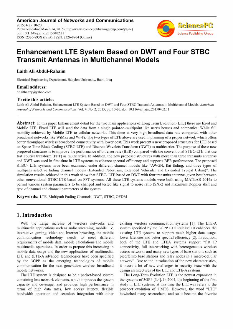
4.3.1. Extended Pedestrian A (EPA) Channel Model
The model of this channel was shown in table (1) first raw.
The simulation had been done to all scenario of STBC-LTE
with DWT and FFT and the simulation result shown in
fig.(20) to fig.(26). In fixed STBC-LTE system it is noted
that the proposed STBC-LTE based on DWT performs better
than STBC-LTE based on FFT. The SNR at a BER 10-4
is
about 19 dB for STBC-LTE based on DWT with 4 antennas
and about 37 dB for STBC-LTE based on FFT with also
using 4 antennas. A gain of about 18 dB has been achieved
by using DWT way over the using FFT system and this value
is much need in the communications systems to save
transmitted power and increase data rate.
Fig. (20). SNR Versus BER to Fixed STBC-LTE-256 subcarriers in Extended
Pedestrian A (EPA) Channel model
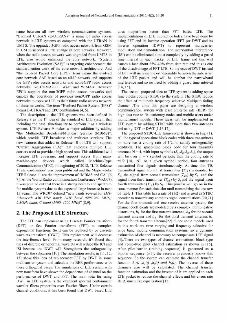
Fig. (21). SNR Versus BER to Mobile STBC-LTE-128 subcarriers in
Extended Pedestrian A (EPA) Channel model - MDS=5Hz
For mobile STBC-LTE system, the results of 128 and 1024
subcarriers (the size of DWT or FFT) only have been found
in three cases of MDS (5Hz, 70 Hz and 300 Hz). It can be
seen from fig. (21) and fig. (22) (for small MDS=5Hz) that
the proposed STBC-LTE based on DWT still performs better
than STBC-LTE based on FFT and the system of STBC still
gives good results for small and large subcarriers (128 and
1024 respectively). The SNR at a BER 10-4
is about 12 dB for
4 antennas in proposed system of 128 and about 17 dB in
1024, while it’s not reach the desired value in STBC-LTE
based on FFT with 128 and 1024 subcarriers. In addition, a
wide improvement span is obtained for all values of SNR in
these systems.
Fig. (22). SNR Versus BER to Mobile STBC-LTE-1024 subcarriers in
Extended Pedestrian A (EPA) Channel model - MDS=5Hz
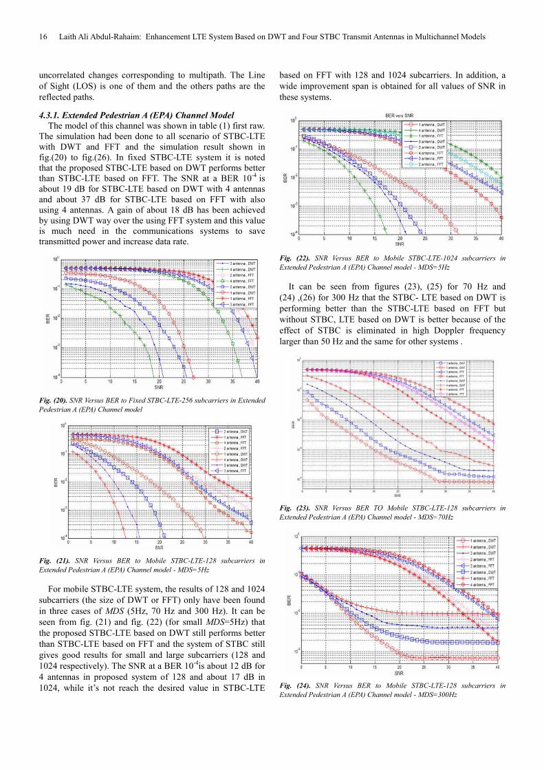
It can be seen from figures (23), (25) for 70 Hz and
(24) ,(26) for 300 Hz that the STBC- LTE based on DWT is
performing better than the STBC-LTE based on FFT but
without STBC, LTE based on DWT is better because of the
effect of STBC is eliminated in high Doppler frequency
larger than 50 Hz and the same for other systems .
Fig. (23). SNR Versus BER TO Mobile STBC-LTE-128 subcarriers in
Extended Pedestrian A (EPA) Channel model - MDS=70Hz
Fig. (24). SNR Versus BER to Mobile STBC-LTE-128 subcarriers in
Extended Pedestrian A (EPA) Channel model - MDS=300Hz

American Journal of Networks and Communications 2015; 4(2): 10-20 17
Fig. (25). SNR Versus BER to Mobile STBC-LTE-1024 subcarriers in
Extended Pedestrian A (EPA) Channel model - MDS=70Hz
Fig. (26). SNR Versus BER to Mobile STBC-LTE-1024 subcarriers in
Extended Pedestrian A (EPA) Channel model - MDS=300Hz
4.3.2. Extended Vehicular A (EVA) Channel Model
In this section the results of Extended Vehicular A (EVA)
channel model will be simulated according to the table (1)
second raw. For fixed system, It is clear from Fig.(27) that
BER performance of STBC-LTE based on DWT is better
than the system of STBC - LTE based on FFT. The SNR at a
BER=10-4
is about 21dB for 4 antennas at proposed system
and cannot been reached for STBC-LTE based on FFT
system and this will give losses in the gain about 20 dB for
proposed system against STBC-LTE with FFT system when
compared with Extended Vehicular A (EVA) channel model.
Fig. (27). SNR Versus BER to Fixed STBC-LTE-256 subcarriers in Extended
Vehicular A (EVA) Channel model
Also for mobile system, the results have simulated only for
128 and 1024 (the size of DWT or FFT) in three cases of
MDS=(5Hz, 70 Hz and 300 Hz).
Fig. (28). SNR Versus BER to Mobile STBC- LTE-128 subcarriers in
Extended Vehicular A (EVA) Channel model - MDS=5Hz
Fig. (29). SNR Versus BER to Mobile STBC-LTE-1024 subcarriers in
Extended Vehicular A (EVA) Channel model - MDS=5Hz
From figure (28) and (29), it can be seen that the proposed
DWT based STBC-LTE still performs better than FFT based
STBC-LTE and the system of STBC still gives good results.
The SNR at a BER 10-4
is about 15 dB for 4 antennas at
proposed system of 128 and about 19 dB for 1024, while it is
cannot been reach in FFT based STBC-LTE system of 128
and 1024, this means losses in gain is about 20 dB for the
proposed STBC-LTE system and cannot been reach for the
traditional system in comparison with the Extended Vehicular
A (EVA) channel model at MDS of 5Hz.
Fig. (30). SNR Versus BER to Mobile STBC-LTE in Extended Vehicular A
(EVA) Channel model -128 subcarriers- MDS=70Hz
18 Laith Ali Abdul-Rahaim: Enhancement LTE System Based on DWT and Four STBC Transmit Antennas in Multichannel Models
Fig. (31). SNR Versus BER to Mobile STBC- LTE in Extended Vehicular A
(EVA) Channel model -128 subcarriers- MDS=300Hz
Fig. (32). SNR Versus BER to Mobile STBC-LTE-1024 subcarriers in
Extended Vehicular A (EVA) Channel model - MDS=70Hz
Fig. (33). SNR Versus BER to Mobile STBC-LTE-1024 subcarriers in
Extended Vehicular A (EVA) Channel model - MDS=300Hz
It can be seen from figures above that the losses will be
increased for both systems due to Doppler Effect.
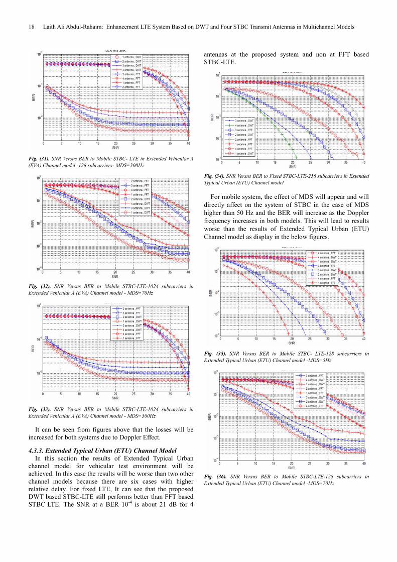
4.3.3. Extended Typical Urban (ETU) Channel Model
In this section the results of Extended Typical Urban
channel model for vehicular test environment will be
achieved. In this case the results will be worse than two other
channel models because there are six cases with higher
relative delay. For fixed LTE, It can see that the proposed
DWT based STBC-LTE still performs better than FFT based
STBC-LTE. The SNR at a BER 10-4
is about 21 dB for 4
antennas at the proposed system and non at FFT based
STBC-LTE.
Fig. (34). SNR Versus BER to Fixed STBC-LTE-256 subcarriers in Extended
Typical Urban (ETU) Channel model
For mobile system, the effect of MDS will appear and will
directly affect on the system of STBC in the case of MDS
higher than 50 Hz and the BER will increase as the Doppler
frequency increases in both models. This will lead to results
worse than the results of Extended Typical Urban (ETU)
Channel model as display in the below figures.
Fig. (35). SNR Versus BER to Mobile STBC- LTE-128 subcarriers in
Extended Typical Urban (ETU) Channel model -MDS=5Hz
Fig. (36). SNR Versus BER to Mobile STBC-LTE-128 subcarriers in
Extended Typical Urban (ETU) Channel model -MDS=70Hz
American Journal of Networks and Communications 2015; 4(2): 10-20 19
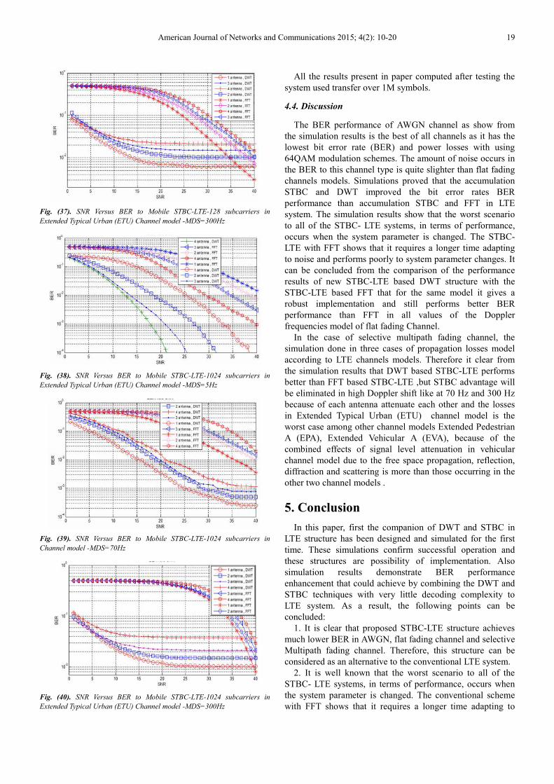
Fig. (37). SNR Versus BER to Mobile STBC-LTE-128 subcarriers in
Extended Typical Urban (ETU) Channel model -MDS=300Hz
Fig. (38). SNR Versus BER to Mobile STBC-LTE-1024 subcarriers in
Extended Typical Urban (ETU) Channel model -MDS=5Hz
Fig. (39). SNR Versus BER to Mobile STBC-LTE-1024 subcarriers in
Channel model -MDS=70Hz
Fig. (40). SNR Versus BER to Mobile STBC-LTE-1024 subcarriers in
Extended Typical Urban (ETU) Channel model -MDS=300Hz
All the results present in paper computed after testing the
system used transfer over 1M symbols.
4.4. Discussion
The BER performance of AWGN channel as show from
the simulation results is the best of all channels as it has the
lowest bit error rate (BER) and power losses with using
64QAM modulation schemes. The amount of noise occurs in
the BER to this channel type is quite slighter than flat fading
channels models. Simulations proved that the accumulation
STBC and DWT improved the bit error rates BER
performance than accumulation STBC and FFT in LTE
system. The simulation results show that the worst scenario
to all of the STBC- LTE systems, in terms of performance,
occurs when the system parameter is changed. The STBC-
LTE with FFT shows that it requires a longer time adapting
to noise and performs poorly to system parameter changes. It
can be concluded from the comparison of the performance
results of new STBC-LTE based DWT structure with the
STBC-LTE based FFT that for the same model it gives a
robust implementation and still performs better BER
performance than FFT in all values of the Doppler
frequencies model of flat fading Channel.
In the case of selective multipath fading channel, the
simulation done in three cases of propagation losses model
according to LTE channels models. Therefore it clear from
the simulation results that DWT based STBC-LTE performs
better than FFT based STBC-LTE ,but STBC advantage will
be eliminated in high Doppler shift like at 70 Hz and 300 Hz
because of each antenna attenuate each other and the losses
in Extended Typical Urban (ETU) channel model is the
worst case among other channel models Extended Pedestrian
A (EPA), Extended Vehicular A (EVA), because of the
combined effects of signal level attenuation in vehicular
channel model due to the free space propagation, reflection,
diffraction and scattering is more than those occurring in the
other two channel models .
5. Conclusion
In this paper, first the companion of DWT and STBC in
LTE structure has been designed and simulated for the first
time. These simulations confirm successful operation and
these structures are possibility of implementation. Also
simulation results demonstrate BER performance
enhancement that could achieve by combining the DWT and
STBC techniques with very little decoding complexity to
LTE system. As a result, the following points can be
concluded:
1. It is clear that proposed STBC-LTE structure achieves
much lower BER in AWGN, flat fading channel and selective
Multipath fading channel. Therefore, this structure can be
considered as an alternative to the conventional LTE system.
2. It is well known that the worst scenario to all of the
STBC- LTE systems, in terms of performance, occurs when
the system parameter is changed. The conventional scheme
with FFT shows that it requires a longer time adapting to

20 Laith Ali Abdul-Rahaim: Enhancement LTE System Based on DWT and Four STBC Transmit Antennas in Multichannel Models
noise and performs poorly to system parameter changes. It
can be concluded from the comparison of the performance of
this new structure with the FFT that for the same model it
gives a robust implementation.
3. In selective Multipath fading channels models, the
simulation results are presented by isolating individual
propagation effects, to discover which channel parameters
have the most significant impact on the performance. In
Doppler shift, it is seen that DWT based STBC- LTE still
performs well better than FFT based STBC- LTE, but STBC
advantage will be eliminated or lost in high Doppler shift
above 50 Hz because of each antenna attenuate each other
and the losses in Extended Typical Urban (ETU) channel
model is the worst case among other channel models
Extended Pedestrian A (EPA), Extended Vehicular A (EVA),.
References
[1] Baig S. and Mughal M. J., 2007 “A Frequency Domain Equalizer in Discrete Wavelet Packet Multitone Transceiver for In-Home PLC LANS”, IEEE International Symposium on Power Line Communications and its Applications, March 2007, PISA, Italy.
[2] Fazelk and S. Kaiser-2002, “Multi-Carrier and Spread Spectrum Systems”. 1st Edition, John Wiley & Sons.
[3] Kitming, Tommy C.-2002, “Hybrids OFDM- CDMA: A Comparison of MC/DS-CDMA, MC-CDMA and OFCDM”, Dept. of Electrical and Electronic, Adelaide University, SA 5005, Australia.
[4] Koga H., N. Kodama, and T. Konishi-2003, "High-speed power line communication system based on wavelet OFDM," in Proc. IEEE ISPLC 2003, Kyoto, Japan, May, pp. 226-231.
[5] Keita I., Daisuke U., and Satoshi D., 2007 “Performance Evaluation of Wavelet OFDM Using ASCET” IEEE.
[6] You-L. C. and Shiao-L. T., 2012 “A Low-Latency Scanning with Association Mechanism for Real-Time Communication in Mobile WiMAX”, IEEE Transactions On Wireless Communications, Accepted For Publication.
[7] Qinghua Shi, Yong Liang Guan, Yi Gong and Choi Look Law, 2009 “Receiver Design for Multicarrier CDMA Using Frequency-Domain Oversampling”, IEEE Transactions on Wireless Communications, Vol. 8, No. 5.
[8] Roberto C. and García A., 2009 “Joint Channel and Phase Noise Compensation for OFDM in Fast-Fading Multipath Applications”, IEEE Transactions on Vehicular Technology, Vol. 58, No. 2.
[9] Sobia B., Gohar N.D., Fazal R., 2005 “An efficient wavelet based MC-CDMA transceiver for wireless communications”, IBCAST
[10] Shun-Te Tseng and James S. Lehnert, 2009 “Windowing for Multicarrier CDMA Systems”, IEEE Transactions on Communications, Vol. 57, No. 10
[11] Third Generation Partnership Project (3GPP), Dec. 2004 “Universal Mobile Telecommunications System (UMTS); Deployment aspects,” (release 6), 3GPP. TS 25.943, version 6.0.0.
[12] Vasily S., Peter N., Gilbert S., Pankaj T., and Christopher H.-1999, “The Application of Multiwavelet Filterbank to Image Processing”, IEEE Transactions on Image Processing, Vol. 8, No. 4, pp(548-563),April.
[13] Yeen, Linnartz J-P and Fettweis G. -1993, “Multicarrier CDMA in Indoor Wireless Radio Networks”. Proc. of IEEE PIMRC 1993,Yokohama, Japan, Sept. , pp.109-13
[14] Yu-Wei Lin, Hsuan-Yu Liu, and Chen-Yi Lee-2005 “A 1-GS/s FFT/IFFT Processor for UWB Applications” IEEE Journal of Solid-State Circuits, Vol. 40, No.8, pp.1726-1735.
[15] Yuan D., Zhang H., Jiang M. and Dalei Wu-2004 “Research of DFT-OFDM and DWT-OFDM on Different Transmission Scenarios.” Proceedings of the 2nd International Conference on Information Technology for Application (ICITA), pp. 31–33.
[16] Zhang H., D. Yuan, M. Jiang and Dalei Wu-2004 “Research of DFT-OFDM and DWT-OFDM on Different Transmission Scenarios.” Proceedings of the 2nd International Conference on Information Technology for Application (ICITA).
[17] Gupta A., Chandavarkar B. R.,2012, “An Efficient Bandwidth Management Algorithm for WiMAX (IEEE 802.16) Wireless Network EBM Allocation Algorithm.” IEEE Industrial and Information Systems (ICIIS).
[18] H. Zarrinkoub “Understanding LTE with MATLAB : from mathematical foundation to simulation, performance evaluation andimplementation” John Wiley & Sons, Ltd,2014
[19] P. Tong, R. C. de Lamare, and A. Schmeink, “Adaptive distributed space-time coding based on adjustable code matrices for cooperative MIMO relaying systems,” IEEE Trans. Commun., vol. 61, no. 7, pp. 2692–2703, Jul. 2013.
[20] Third Generation Partnership Project (3GPP), “Evolved Universal Terrestrial Radio Access (E-UTRA); Physical Channels and Modulation,” standard specifications TS 36.211, 2009, available on www.3gpp.org, accessed on February 10, 2014.
[21] M. Suryanegara, and M.Asvial, “In Searching for 4G Mobile Service Applications: The Case of Indonesia Market,” Telecommunications Journal of Australia, Vol.63, No.2, 2013.
[22] His-LuChao,Chia-kai Chang,Chia-Iung Liu, "A novel channel-aware frequency-domain scheduling in LTE uplink", Wireless Communication and Networking Conference (WCNC),2013 IEEE