BS EN 474-8-2006+A1-2009 Earth-moving machinery — Safety — P.pdf
Upload
alaa-ramadanCategory
view
216download
0
8/11/2019 English_2080-SG001A-EN-P.pdf
http://slidepdf.com/reader/full/english2080-sg001a-en-ppdf 1/12
Micro800 Programmable ControllersBulletin 2080Selection Guide
8/11/2019 English_2080-SG001A-EN-P.pdf
http://slidepdf.com/reader/full/english2080-sg001a-en-ppdf 2/12
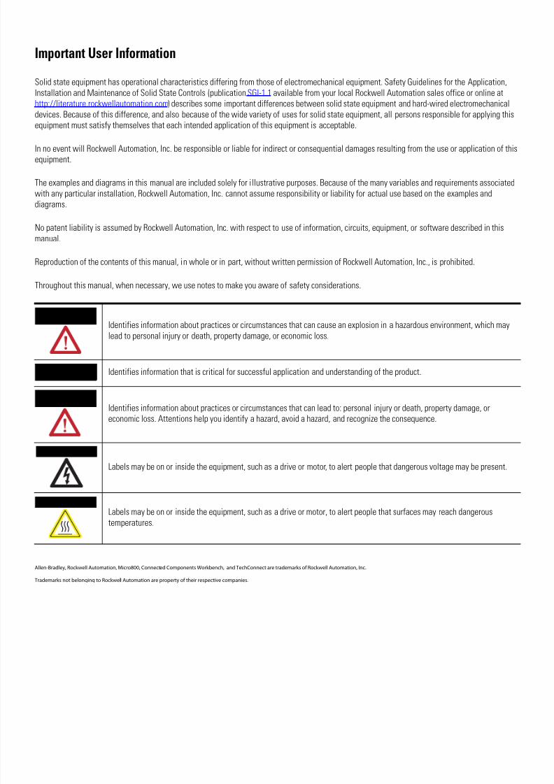
Important User Information
Solid state equipment has operational characteristics differing from those of electromechanical equipment. Safety Guidelines for the ApplicatioInstallation and Maintenance of Solid State Controls (publicationSGI-1.1 available from your local Rockwell Automation sales office or online athttp://literature.rockwellautomation.com) describes some important differences between solid state equipment and hard-wired electromechanicadevices. Because of this difference, and also because of the wide variety of uses for solid state equipment, all persons responsible for applying equipment must satisfy themselves that each intended application of this equipment is acceptable.
In no event will Rockwell Automation, Inc. be responsible or liable for indirect or consequential damages resulting from the use or applicationequipment.
The examples and diagrams in this manual are included solely for illustrative purposes. Because of the many variables and requirements associwith any particular installation, Rockwell Automation, Inc. cannot assume responsibility or liability for actual use based on the examples anddiagrams.
No patent liability is assumed by Rockwell Automation, Inc. with respect to use of information, circuits, equipment, or software described in thmanual.
Reproduction of the contents of this manual, in whole or in part, without written permission of Rockwell Automation, Inc., is prohibited.
Throughout this manual, when necessary, we use notes to make you aware of safety considerations.
Allen-Bradley, Rockwell Automation, Micro800, Connected Components Workbench, and TechConnect are trademarks of Rockwell Automation, Inc.
Trademarks not belonging to Rockwell Automation are property of their respective companies.
WARNINGIdentifies information about practices or circumstances that can cause an explosion in a hazardous environment, which mlead to personal injury or death, property damage, or economic loss.
IMPORTANT Identifies information that is critical for successful application and understanding of the product.
ATTENTION
Identifies information about practices or circumstances that can lead to: personal injury or death, property damage, oreconomic loss. Attentions help you identify a hazard, avoid a hazard, and recognize the consequence.
SHOCK HAZARD
Labels may be on or inside the equipment, such as a drive or motor, to alert people that dangerous voltage may be presen
BURN HAZARDLabels may be on or inside the equipment, such as a drive or motor, to alert people that surfaces may reach dangeroustemperatures.

8/11/2019 English_2080-SG001A-EN-P.pdf
http://slidepdf.com/reader/full/english2080-sg001a-en-ppdf 3/12
1 Publication 2080-SG001A-EN-P - December 2010
Micro800 Controller Comparison
Feature
Attribute Micro810, 12-point Micro830, 10/16-point Micro830, 24-point Micro830, 48 -point
Communications ports,embedded
USB (with USB adapter) USB 2.0 (non-isolated)
RS232/RS485 non-isolated combo serial
Base digital I/O points(see Micro800Input/Outputs on page 3)
12 10/16 24 48
Base analog I/O channels Four 24V DC digital inputscan be configured as 0…10Vanalog inputs (DC inputmodels only)
None
Base number of plug-inmodules
0 2 3 5
Types of accessories orplug-ins supported
•LCD display with backupmemory module
•USB adapter
All plug-in modules (Isolated serial port, 2/4-channel analog, RTD/TC, trimpot, backupmemory module with RTC)
AXIS/HSC, max (100 kHzpulse)
No motion support 1 axis /2 HSC 2/4 3/6
NOTE: number of HSC is half of stated value if Preset and Enable signals are used (4 wire)
Power supply AC and DC Power supplyembedded
Base unit has embedded 24V DC power supply, optional external 120/240V AC power supplyavailable
Basic instruction speed 2.5µ s per basic instruction 0.25µ s per basic instruction
Micro800 Controller Programming Comparison (with Connected Components Workbench)
Attribute Micro810, 12-point Micro830, 10/16-point Micro830, 24-point Micro830, 48 -point
Program steps(1) 2 KB 4 KB 10 KB 10 KB
Data bytes 4 KB 8 KB 20 KB 20 KB
IEC 61131-3 languages Ladder diagram, function block, structured text
User defined function blocks Yes
Emulator Yes (optional - only with Developer edition)
Motion instructions (planned) n.a. PLCopen motion instruction set
Positioning only - Home, Move, etc.
Floating point Yes, 32-bit & 64-bit
PID None Yes
Run-time download n.a. Yes – individual routines downloadable while in RUN mode
Embedded serial port protocols None Modbus Master/Slave, ASCII/Binary
(1) Estimated Program and Data size are “typical” — program steps and variables are created dynamically. 1 Program Step = 12 data bytes.

8/11/2019 English_2080-SG001A-EN-P.pdf
http://slidepdf.com/reader/full/english2080-sg001a-en-ppdf 4/12
Publication 2080-SG001A-EN-P - December 2010
2 Micro800 Programmable Controllers Selection Guide
Micro800 Catalog Number Details
Micro800 Power Requirements
Controller/Module Power Requirement
Micro810 12 point(with or without LCD)
3W (5V A for AC module)
Micro830 (without plug-in)10/16 point24 point48 point
3.6W5.28W10.56W
Plug-in modules, each 1.44W
Micro800 Controller Analog I/O comparison
Analog Accuracy Level Required Component Recommended
Low Micro810 - 4-channel embedded analog- 10-bit non-isolated 0…10V inputs- 2% Accuracy with user calibration- limited filtering- each channel shared with digital input
Medium Micro830 (with plug-ins)- 12-bit non-isolated 0…10V, 0…20 mA- 1% Accuracy, inputs and outputs- 14-bit non-isolated RTD/TC (1 °C accuracy)- 200 ms/ch, 50/60 Hz Ffltering
2080 - LC 30- 24 Q V B
Power SupplyA=120/240V ACB=24V DCD=12V DC
Output Type:B= 24V DC SourceV = 24V DC SinkW = Relay
Bulletin Number
Base UnitLC10 - Micro810LC30 - Micro830
Number of I/O10, 12, 16, 24, 48
Input Type:A = 110V AC or 110/220V ACQ = 24V AC/DCD = 12V DC

8/11/2019 English_2080-SG001A-EN-P.pdf
http://slidepdf.com/reader/full/english2080-sg001a-en-ppdf 5/12
Publication 2080-SG001A-EN-P - December 2010
Micro800 Programmable Controllers Selection Guide 3
Micro800 Input/Outputs
1.5" LCD and Keypad not included with the controller
Micro810 Controllers - Number and Type of Inputs/Outputs (1)
Catalog Number Power Inputs Outputs Analog In 0…10V(shared with DC In)
120V AC 240V AC 12…24V DC /V AC Relay 24 V DC SRC
2080-LC10-12QWB 24V DC 8 4 4
2080-LC10-12AWA 120…240V AC 8 4
2080-LC10-12QBB 12…24V DC 8 4 4
2080-LC10-12DWD 12V DC 8 4 4
(1) Micro810 controllers have high current relay outputs. Two are 8A relays and two are 4A relays.

8/11/2019 English_2080-SG001A-EN-P.pdf
http://slidepdf.com/reader/full/english2080-sg001a-en-ppdf 6/12
Publication 2080-SG001A-EN-P - December 2010
4 Micro800 Programmable Controllers Selection Guide
Micro830 Controllers - Number and Type of Inputs/Outputs (1)
Catalog Number Inputs Outputs
110V AC 24V DC/V AC Relay 24V Sink 24V Source
2080-LC30-10QWB 6 4
2080-LC30-10QVB 6 4
2080-LC30-16AWB 10 6
2080-LC30-16QWB 10 6
2080-LC30-16QVB 10 6
2080-LC30-24QBB 14 10
2080-LC30-24QVB 14 10
2080-LC30-24QWB 14 10
2080-LC30-48AWB 28 20
2080-LC30-48QBB 28 20
2080-LC30-48QVB 28 20
2080-LC30-48QWB 28 20
(1) All power is 24V DC
8/11/2019 English_2080-SG001A-EN-P.pdf
http://slidepdf.com/reader/full/english2080-sg001a-en-ppdf 7/12
Publication 2080-SG001A-EN-P - December 2010
Micro800 Programmable Controllers Selection Guide 5
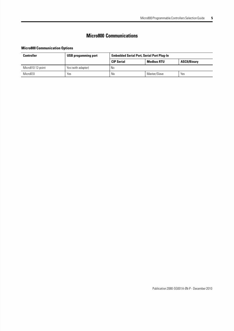
Micro800 Communications
Micro800 Communication Options
Controller USB progamming port Embedded Serial Port, Serial Port Plug-In
CIP Serial Modbus RTU ASCII/Binary
Micro810 12-point Yes (with adapter) No
Micro830 Yes No Master/Slave Yes

8/11/2019 English_2080-SG001A-EN-P.pdf
http://slidepdf.com/reader/full/english2080-sg001a-en-ppdf 8/12
Publication 2080-SG001A-EN-P - December 2010
6 Micro800 Programmable Controllers Selection Guide
Connected Components Workbench
Connected Components Workbench (CCW) is the programming and configurationsoftware environment for the Micro800 controllers and our Connected Components
products offering. It simplifies setup and usage, enabling applications ranging fromsimple Smart Relay up to Standalone Machine control with EtherNet/IP (planned).
Visit the website for the most up-to-date product information, downloads and tools:http://www.ab.com/programmable-controllers/micro800.
Connected Components Workbench versions
Attribute Basic Developer
Delivery Download for FREE from the Connected Components Workbench webpage at http://www.ab.com/programmable-controllers/micro800.
DVD available for order
9328-CCWDEVENE
Packaging options Available on DVD, orderable from Connected Components Workbench
web page at http://www.ab.com/programmable-controllers/micro800.
Available as part of our software toolkit program
Features - LD, FBD and ST editors
- creatable user-defined function blocks
- No activation needed
- Optional registration during installation (for product updates andnotices)
Adds these features to the Basic edition:
- run-time download (program swap)
- controller simulator/emulator

8/11/2019 English_2080-SG001A-EN-P.pdf
http://slidepdf.com/reader/full/english2080-sg001a-en-ppdf 9/12
Publication 2080-SG001A-EN-P - December 2010
Micro800 Programmable Controllers Selection Guide 7
Micro800 Plug-in Modules and Accessories
Plug-in / Accessory Supported by Micro810 Supported by Micro830 Feature
1.5" LCD and Keypad Yes No • backup module for Micro810 controllers• configure Smart Relay Function Blocks
Micro810 USB Adapter2080-USBADAPTER
Yes N.A. USB programming access
External Power Supply2080-PS120-240VAC
Yes Yes expansion power supply
RS232/485 Isolated Serial Port2080-SERIALISOL
No Yes • adds additional serial communications with ModbusRTU and ASCII protocols
• isolated for increased noise immunity
Non-isolated Unipolar AnalogInput/Output2080-IF2, 2080-IF4, 2080-OF2
No Yes • adds up to 20 embedded analog I/O with 12-bitresolution (with 48-point controllers)
•2 channels for -IF2, OF2•4 channels for -IF4
Non-isolated Thermocouple2080-TC2
No Yes • for temperature control, when used with PID withautotuning
•2 channels for -TC2 and -RTD2Non-isolated RTD2080-RTD2
No Yes
Memory Module with RTC2080-MEMBAK-RTC
No Yes • backup project data and application code• high accuracy real-time clock
6-Channel Trim PotentiometerAnalog Input2080-TRIMPOT6
No Yes adds six analog presets for speed, position andtemperature control

8/11/2019 English_2080-SG001A-EN-P.pdf
http://slidepdf.com/reader/full/english2080-sg001a-en-ppdf 10/12
Publication 2080-SG001A-EN-P - December 2010
8 Micro800 Programmable Controllers Selection Guide
For More Information Visit the Micro800 website athttp://www.ab.com/programmable-controllers/micro800 to learn more aboutMicro800 products and download Connected Component Workbench software andMicro800 firmware updates.
If you would like a manual, you can:• download a free electronic version from the Internet:
http://literature.rockwellautomation.com.• purchase a printed manual by contacting your local Allen-Bradley distributor
or Rockwell Automation representative.

8/11/2019 English_2080-SG001A-EN-P.pdf
http://slidepdf.com/reader/full/english2080-sg001a-en-ppdf 11/12

8/11/2019 English_2080-SG001A-EN-P.pdf
http://slidepdf.com/reader/full/english2080-sg001a-en-ppdf 12/12
Rockwell Otomasyon Ticaret A.Ş., Kar Plaza İş Merkezi E Blok Kat:6 34752 İçerenköy, İstanbul, Tel: +90 (216) 5698400
Publication 2080-SG001A-EN-P - December 2010
Rockwell Automation Support
Rockwell Automation provides technical information on the Web to assist you in using its products.At http://www.rockwellautomation.com/support/, you can find technical manuals, a knowledge base of FAQs, technical andapplication notes, sample code and links to software service packs, and a MySupport feature that you can customize to make the
best use of these tools.
For an additional level of technical phone support for installation, configuration, and troubleshooting, we offer TechConnectsupport programs. For more information, contact your local distributor or Rockwell Automation representative,or visit http://www.rockwellautomation.com/support/.
Installation Assistance
If you experience a problem within the first 24 hours of installation, review the information that is contained in this manual.You can contact Customer Support for initial help in getting your product up and running.
New Product Satisfaction Return
Rockwell Automation tests all of its products to ensure that they are fully operational when shipped from the manufacturing facilitHowever, if your product is not functioning and needs to be returned, follow these procedures.
Documentation Feedback
Your comments will help us serve your documentation needs better. If you have any suggestions on how to improve this document,complete this form, publicationRA-DU002, available athttp://www.rockwellautomation.com/literature/.
United States or Canada 1.440.646.3434
Outside United States orCanada
Use the Worldwide Locator at http://www.rockwellautomation.com/support/americas/phone_en.html, or contactyour local Rockwell Automation representative.
United States Contact your distributor. You must provide a Customer Support case number (call the phone number above to obtainone) to your distributor to complete the return process.
Outside United States Please contact your local Rockwell Automation representative for the return procedure.