
SunGuide TM Software Development Project Release 4.0 Data Fusion Follow-Up DR Jan. 8, 2008
Upload
ahmet-gelisliCategory
view
40download
5
HDPE Fusion Manual
Coming through.
CORPORATE HQISCO Industries, LLC
926 Baxter AvenueBox 4545
Louisville, Kentucky 40204Tel. 800.345.4726Fax 800.831.4726
www.isco-pipe.com
1-800-345-ISCO
For HDPE, contractors know. Just call…
Connectingthe ResourcesYou Need
Version 4.0 2012

ISCO Industries LLC., is the world’s largest McElroy Distributor and offers a complete line of fusion accessories and special tooling.
Fusion Equipment for rent or sale:• ButtFusionMachines• SidewallFusionMachines• SocketFusionEquipment• CoiledPipeTrailers• ElectrofusionEquipment• ExtrusionWelders• HotAirGuns Rental & Sales Locations:• Salesandrentallocations nationwide,whichfeaturesthe newMcElroyTracStar®lineofself propelledandselfcontainedunits.• NewandUsedEquipment: LeasetoOwnOptionsAvailable• MultipleMcElroyAuthorizedServiceand RepairCenterstosupportyouandyour equipment.
Field Fusion TechniciansExperienced,FactoryTrained,ConfinedSpaceCertifiedandOSHACompliant
Need Training?ISCOoffersFusionOperatingTrainingQualificationclassesorMcElroyCertifiedFusionOperatorTrainingclasses.ContactyourISCOsalesrepformoreinformation.
WelcometothemostcomprehensiveFusionManualintheindustry.Aftergather-inginformationfromManufacturersandthePlasticPipeInstitute,wefeelthisisthe“goto”manualwhenjoiningHDPEpipe.TheproceduresshownusePlasticPipeInstitute’sGenericSaddleFusionJoiningProcedure,TR-41anditsGenericButtFusionJoiningProcedure,TR-33astheirfoundations.HDPEpipeandfittingsmanufacturershaveapprovedP.P.I.’sGenericJoiningProceduresinanattempttostandardizethejoiningproceduresofHDPE.TheASTMSTANDARDF2620andASTMstandardF1056arestillthecornerstonesforsocketfusion.Itsjoiningpro-cedureisdetailedandhighlightedinthisfusionproceduresmanual.Do Not join Driscopipe 7000 or 8000 series products using these procedures. Reference ASTM STANDARD F2620 for Cold Weather Procedures when performing Socket, Saddle, and Butt Fusions in extreme cold conditions.
We’reproudtoofferqualityproductsandskilledprofessionalsnationwide,dedi-catedtoprovidingexceptionalcustomerservice,especiallyourfusionequipment,sales,rental,repair,refurbishmentandtrainingsupportsystem.Ifyouhaveaquestionaboutfusion,pleasecallourtollfreehotlineat1-800-345-ISCO(4726)ext-4790andaqualifiedservicetechnicianwillansweryourquestions.
TheISCOFusionManualhasbeenendorsedbyMcElroyManufacturing,Inc.andtheirTechnicalSupportStaff,howeverthismanualshouldnotbeconsideredasubstitutefortheoriginalmanufacturer’sfusionequipmentmanuals.Alwaysreadandunderstandtheoriginalmanufacturer’sequipmentmanualbeforeoperat-inganypieceofequipment.Theoperatormustbethroughlytrainedintheproperuseoffusionequipmentandprocedures.WeareproudtobeadistributorofMcElroyHDPEFusionEquipmentandfeaturetheirequipmentinthismanual.ISCOisgearedtowardseducatingeveryonewiththeproperfusionprocduressothatHDPEcancontinuetogrowinthemarketplaceasthepipingmaterialofchoice.Theoperator’strainingandjudgementisparamounttothesuccessoffusingHDPEproducts.Theappropriatenessoftheproceduresinvolvedshouldbeconsideredbeforestartinganyproject.WehopethismanualaidesyouinthesafehandlingandjoiningofHDPEproductsinamoreeffectiveandefficientmanner.
Thankyouforyourbusinessandcontinuedinterestinourproductsandsevices.WelookforwardtoservingyouonyournextHDPEproject.
IfyouhaveanyquestionsregardingthismanualorinjoiningHDPEpipe,pleasecontactourFusionHotlineat1-800-345-ISCO(4726),ext.4790.
Haveaprobleminthefieldandneedhelp?-GiveusaCall-
FusionTroubleshootingHotline
1-800-345-4726Ext.4790
Fusion Equipment and Services
Accessories & Special Tooling:• PolyPorter™• PolyHorse™• LimitedAccessEquipment• SqueezeOffTools• SplitRingHeaters• DataLoggers™• PipeCuttingTools• TestCaps• Pyrometers• InternalandExternalBeadRemovers• PipeStraighteningEquipment• PipeReroundingTools• AndManyOthers
Work with It, Not on It!ISCOIndustrieshasmultipleMcElroyAuthorizedServiceandRepairCenterswithacompleteinventoryoffusionunitsandparts.Formoreinformationaboutrepairingorrefurbishingyourfusionunit,call1-800-345-ISCO(4726),www.isco-pipe.com
Before and After photos of equipment refurbished by ISCO Industries

Table of Contents
This manual contains accurate and reliable information to the best of our knowledge as of the publication date. The results of using our suggestions and recommendations cannot be guaranteed because the conditions of use are beyond our control. Failure to follow these procedures in this manual may result in damage to or destruction of property and/or serious injury to or death of a person. The user of such information assumes all risk connected with the use thereof. ISCO Industries, LLC assumes no responsibility for the use of information presented herein and hereby disclaims all liability in regard to such use.
ISCO Fusion Manual
3
Fusion Equipment Safety Information . . . . . . . . Page 4
Tips For Success . . . . . . . . . . . . . . . . . . . . . . . . . . . . . Page 15
Manual Butt Fusion Machine Procedure . . . . . . . Page 18
Hydraulic Butt Fusion Machine Procedure . . . . Page 32
Saddle Fusion Machine Procedure . . . . . . . . . . . Page 51
Socket Tooling and Fusion Procedure . . . . . . . . . Page 65
Reference Information: McElroy’s DataLogger™, Pendant/Coach™ Equipment & Fusion Pressure Charts . . . . . . . . . Page 75
Fusion Hotline 1-800-345-ISCO ext. 4790© Copyright 2012 ISCO Industries, LLC All rights reserved.

4
Fusion Hotline 1-800-345-ISCO ext. 4790© Copyright 2012 ISCO Industries, LLC All rights reserved.
Fusion EquipmentSafety Information
Please read the Safety Section first.
How was I
suppose to know?

Safety Alerts
This hazard alert sign ! appears in this manual.When you see this sign, carefully read what it says.YOUR SAFETY IS AT STAKE.
You will see the hazard alert sign with these words:DANGER, WARNING, and CAUTION.
In this manual you should look for two other words:NOTICE and IMPORTANT.
NOTICE: Can keep you from doing something that might damage the machine or some-one’s property. It may also be used to alert against unsafe practices.
IMPORTANT: Can help you do a better job or make your job easier in some way.
ISCO Fusion Manual
5
Fusion Hotline 1-800-345-ISCO ext. 4790© Copyright 2012 ISCO Industries, LLC All rights reserved.
!! DANGER
! WARNING
! CAUTION
! DANGER
WARNING!
CAUTION! Indicates a hazardous situation which,if not avoided, may result in minor ormoderate injury.
Indicates a potentially hazardoussituation which, if not avoided, couldresult in death or serious injury.
Indicates an imminently hazardous situation which, if not avoided, willresult in death or serious injury.
Read And Understand
Do not operate fusion equipment until you have carefully read, and understand the “Safety” and “Operation” sections of this manual, and all other equipment manuals that will be used with it.
Your safety and the safety of others dependsupon care and judgement in the operationof this equipment.
Follow all applicable federal, state, local, and industry specific regulations.
Fusion Equipment Safety Information

ISCO Fusion Manual
6
Fusion Hotline 1-800-345-ISCO ext. 4790© Copyright 2012 ISCO Industries, LLC All rights reserved.
ISCO Industries, LLC cannot anticipate every possible circumstance that may involve a potential hazard. The warnings in this manualand on the machine are therefore not all inclusive. You must satisfy yourself that a procedure, tool,work method, or operating technique is safe foryou and others. You should also ensure that the machine will not be damaged or made unsafe by the method of operation or maintenance you choose.
General SafetySafety is important. Report anything unusual that you notice during set up or operation.
Listen for thumps, bumps, rattles, squeals, air leaks, or unusual sounds.
Smell odors like burning insulation, hot metal,burning rubber, hot oil, or natural gas.
Sense any changes in the way the equipment operates.
See problems with wiring and cables, hydraulicconnections, or other equipment.
Report anything you see, feel, smell, or hear that is different from what you expect, or that you think may be unsafe.
Wear Safety EquipmentWear a hard hat, safety shoes, safety glasses, and other applicable personal protection equipment.
Remove jewelry and rings, and do not wear loose-fitting clothing or long hair that could catch on controls or moving machinery.
Fusion Equipment Safety Information
ISCO Fusion Manual
7
Fusion Hotline 1-800-345-ISCO ext. 4790© Copyright 2012 ISCO Industries, LLC All rights reserved.
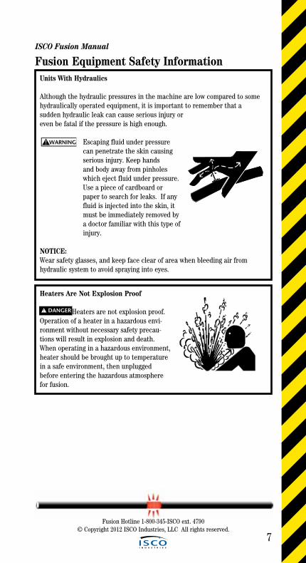
Fusion Equipment Safety InformationUnits With Hydraulics
Although the hydraulic pressures in the machine are low compared to some hydraulically operated equipment, it is important to remember that a sudden hydraulic leak can cause serious injury or even be fatal if the pressure is high enough.
Escaping fluid under pressure can penetrate the skin causing
serious injury. Keep hands and body away from pinholes which eject fluid under pressure. Use a piece of cardboard or paper to search for leaks. If any fluid is injected into the skin, it must be immediately removed by a doctor familiar with this type of injury.
NOTICE: Wear safety glasses, and keep face clear of area when bleeding air from hydraulic system to avoid spraying into eyes.
WARNING!
Heaters Are Not Explosion Proof
Heaters are not explosion proof. Operation of a heater in a hazardous envi-ronment without necessary safety precau-tions will result in explosion and death. When operating in a hazardous environment, heater should be brought up to temperature in a safe environment, then unplugged before entering the hazardous atmosphere for fusion.
! DANGER

ISCO Fusion Manual
8
Fusion Hotline 1-800-345-ISCO ext. 4790© Copyright 2012 ISCO Industries, LLC All rights reserved.
Fusion Equipment Safety InformationElectric Motors Are Not Explosion Proof
Electric Motors are not explo- sion proof. Operation of these components in a hazardous environment without necessary safety precautions will result in explosion or death. When operating in a hazardous environment, keep pump motor and chassis in a safe area by using hydrau-lic extension hoses.
Electrical Safety
Always ensure power cords are properly grounded. It is important to remember that whenyou are working in a wet environment withelectrical devices, proper ground connectionshelp to minimize the chances of an electric shock.
Frequently inspect electrical cords and unit for damage. Damaged components need to replaced and service performed by a qualified electrician.Do not carry electrical devices by the cord.
NOTICE: Always connect units to the proper power source as listed on the unit, or in the owner’s manual. On units with two power cords, plug each cord into separate power circuits. Do not plug into both out-lets of one duplex receptacle.
NOTICE: Disconnect the machine from the power source before attempting any maintenance or adjustment.
! DANGER
WARNING!

ISCO Fusion Manual
9
Fusion Hotline 1-800-345-ISCO ext. 4790© Copyright 2012 ISCO Industries, LLC All rights reserved.
Fusion Equipment Safety InformationCrush Points
Hydraulically operated jaws areoperated under pressure. Anything caught in the jaws will be crushed. Keep fingers, feet, arms, legs, and head out of the jaw area. Always check pipe alignment with a pencil or similar object.
Facer Blades Are Sharp
Facer blades are sharp and can cut.Never attempt to remove shavings while the faceris running, or is in the facing position between thejaws. Use care when operating the facer, and han-dling the unit.
NOTICE: Disconnect power from the facer, and remove the facer blades before attempting any maintenance or adjustment.
Heater Is Hot
The heater is hot and will burn cloth-ing and skin. Keep the heater in its insulated heater stand or sling blanket when not in use, and use care when heating the pipe.
NOTICE: Use only a clean non-synthetic cloth such as a cotton cloth to clean the heater plates.
Fusion Procedures
Follow the procedures carefully, and adhere to all specified parameters.Failure to follow procedures could result in a bad weld. Always follow the proper fusion procedures.
WARNING!
WARNING!
CAUTION!
CAUTION!

ISCO Fusion Manual
10
Fusion Hotline 1-800-345-ISCO ext. 4790© Copyright 2012 ISCO Industries, LLC All rights reserved.
Fusion Equipment Safety InformationUnits With Gas Engines
Handle fuel with care. Fuel is highly flammable. Do not refuel the machinewhile smoking or near open flames or sparks. Always stop the engine before refueling machine. Fill fuel tank outdoors.Help prevent fires by keeping machine cleanof accumulated trash, grease, debris, and facer shavings. Always clean up spilled fuel.
Breathing exhaust gases can cause sickness or death. Always operate machine out-doors in an area with adequate ventilation.
Units With Batteries
Sulfuric acid in battery electrolyte is poisonous. It is strong enough to burn skin, eat holes in clothing, and cause blindness if splashed into eyes. Avoid contact with eyes, skin, and clothing. Exploding gases from battery could cause blindness or serious injury. Keep sparks, flames and cigarettes away.
Have Tires Properly Serviced
Failure to follow proper procedures when mounting a tire on a wheel or rim can pro-duce an explosion which may result in serious injury or death. Have tires mounted by someone that is experienced, and has the equipment to perform the job safely.
WARNING!
CAUTION!
WARNING!
WARNING!
ISCO Fusion Manual
11
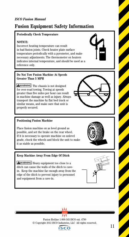
Fusion Equipment Safety InformationPeriodically Check Temperature
NOTICE:Incorrect heating temperature can resultin bad fusion joints. Check heater plate surface temperature periodically with a pyrometer, and makenecessary adjustments. The thermometer on heaters indicates internal temperature, and should be used as a reference only.
0 7 6
Do Not Tow Fusion Machine At Speeds Greater Than 5 MPH
The chassis is not designed for over-road towing. Towing at speeds greater than five miles per hour can result in machine damage as well as injury. Always transport the machine by flat bed truck or similar means, and make sure that unit is properly secured.
Positioning Fusion Machine
Place fusion machine on as level ground as possible, and set the brake on the rear wheel.If it is necessary to operate machine on unlevelgrade, chock the wheels and block the unit to makeit as stable as possible.
Keep Machine Away From Edge Of Ditch
Heavy equipment too close to a ditch can cause the walls of the ditch to cave-in. Keep the machine far enough away from the edge of the ditch to prevent injury to personneland equipment from a cave-in.
WARNING!
WARNING!
Fusion Hotline 1-800-345-ISCO ext. 4790© Copyright 2012 ISCO Industries, LLC All rights reserved.

ISCO Fusion Manual
12
Fusion Equipment Safety Information
Do Not Attempt to Tow A TracStar Fusion Machine
The machine is not designed for towing. Attempting to tow the machine can result in machine damage. Always transport the machine by flat bed truck or similar means, and make sure that unit is properly secured.
Operating TracStar Fusion Machines
Place fusion machine on as level groundas possible.
If it is necessary to operate machine on unlevel grade, make sure that the ground is stable. Some unstable conditions maybe ice, snow, mud, and loose gravel.
For operation safety, never operatemachine on a grade steeper than 30%. (A 3 foot elevation change in 10 feet.)
Positioning Fusion Machine
Place fusion machine on as level ground as possible. If it is neces-sary to operate machine on unlevel grade, chock the tracks and block the unit to make it as stable as possible.
WARNING!
CAUTION!
Hearing Protection Required For TracStar 412 and TracStar 618.
When operating machine for more than four hours per day, wear hearing protection.
10
3
Fusion Hotline 1-800-345-ISCO ext. 4790© Copyright 2012 ISCO Industries, LLC All rights reserved.

ISCO Fusion Manual
13
Fusion Equipment Safety InformationSafety Precautions For Guarding Against Static Electricity And Gaseous Ignition
Polyethylene plastic pipe does not readily conduct electricity. A static electricity charge can buildup on inside and outside surfaces and stay on the pipe surface until some grounding device, such as a tool or a person comes close enough for the static electricity to discharge to the grounding device.
Discharging one part of the pipe surface will not affect other charged areas because static electricity does not flow readily from one area to another. Polyethylene pipe cannot be discharged by attaching grounding wires to the pipe.
Heaters, electric facers and electric power tools are NOT explosion proof. Static electricity discharge can ignite a flammable gas or combustible dust atmosphere.
A static electricity discharge to a person, a tool, or a grounded object close to the pipe surface can cause an electric shock or a spark that can ignite a flam-mable gas or combustible dust atmosphere causing fire or explosion.
In gas utility applications, static electricity can be a potential safety haz- ard. Where a flammable gas-air mixture may be encountered and static charges may be present, such as when repairing a leak, squeezing-off an open pipe, purging, making a connection, etc., arc preventing safety pre- cautions are necessary. Observe all procedures for static electricity safety and control, including procedures for discharging static electricity and requirements for personal protection. Take steps to discharge static electricity from the surface of the polyeth- ylene gas pipe. Such steps include wetting the entire exposed pipe sur- face with a conductive anti-static liquid or a dilute soap and water solu- tion, then covering or wrapping the entire wetted, exposed pipe surface with grounded wet burlap, conductive poly film, or wet tape conductor. The external covering should be kept wet by occasional re-wetting with anti-static solution. The covering or tape should be suitably grounded such as to a metal pin driven into the ground. Steps that discharge the outer surface do not discharge the inner surface of the pipe. Squeeze-off purging, venting, cutting, etc., can still result in a static electricity discharge. When appropriate, ground tools and remove all potential sources of ignition.
WARNING!
! DANGER
Fusion Hotline 1-800-345-ISCO ext. 4790© Copyright 2012 ISCO Industries, LLC All rights reserved.
ISCO Fusion Manual
14
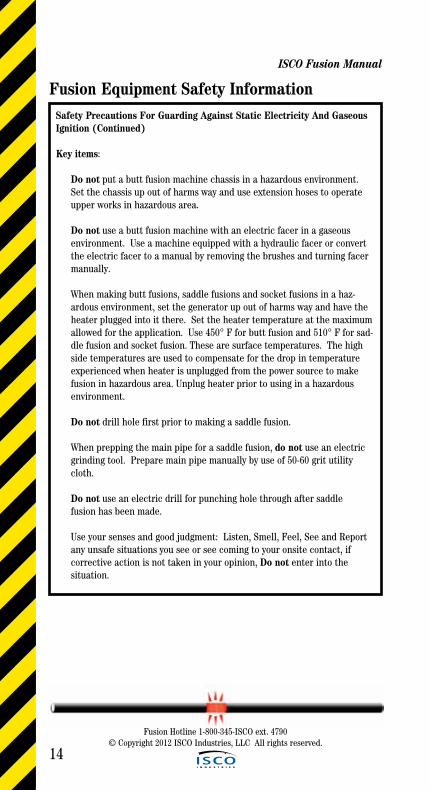
Fusion Equipment Safety InformationSafety Precautions For Guarding Against Static Electricity And Gaseous Ignition (Continued)
Key items:
Do not put a butt fusion machine chassis in a hazardous environment. Set the chassis up out of harms way and use extension hoses to operate upper works in hazardous area.
Do not use a butt fusion machine with an electric facer in a gaseous environment. Use a machine equipped with a hydraulic facer or convert the electric facer to a manual by removing the brushes and turning facer manually.
When making butt fusions, saddle fusions and socket fusions in a haz- ardous environment, set the generator up out of harms way and have the heater plugged into it there. Set the heater temperature at the maximum allowed for the application. Use 450° F for butt fusion and 510° F for sad- dle fusion and socket fusion. These are surface temperatures. The high side temperatures are used to compensate for the drop in temperature experienced when heater is unplugged from the power source to make fusion in hazardous area. Unplug heater prior to using in a hazardous environment.
Do not drill hole first prior to making a saddle fusion.
When prepping the main pipe for a saddle fusion, do not use an electric grinding tool. Prepare main pipe manually by use of 50-60 grit utility cloth. Do not use an electric drill for punching hole through after saddle fusion has been made.
Use your senses and good judgment: Listen, Smell, Feel, See and Report any unsafe situations you see or see coming to your onsite contact, if corrective action is not taken in your opinion, Do not enter into the situation.
Fusion Hotline 1-800-345-ISCO ext. 4790© Copyright 2012 ISCO Industries, LLC All rights reserved.
15
Fusion Hotline 1-800-345-ISCO ext. 4790© Copyright 2012 ISCO Industries, LLC All rights reserved.
Tips For Success
What can I learn from others before getting
started?
Tips
for S
ucce
ss
16
Tips for Success
ISCO Fusion Manual
Use Personal Safety Equipment. Always wear a hard hat and protective boots. Gloves protect hands from heater burns and sharp blades on the
facer. Protective Eye Glasses are also a good idea.
Make sure all equipment is in good working order and power cords are free of cuts with grounding blade on receptacle in tack.
Position fusion equipment on level ground whenever possible.
If the fusion equipment has wheels, set the wheel lock or block them.
Position pipe support stands on either side of the fusion equipment approximately 20’ from ends of the fusion equipment. Adjust stands so
that pipes are level to reduce drag.
When working with McElroy Self-Contained fusion units excluding the T-500 and T-900, make sure to open the facer valve prior to starting the
unit and keep it open until started. Close valve once unit is running. This will save the battery and keep you from burning up the starter.
Plug heater in on self-contained fusion units only after unit has been started and warmed up. Unplug heater before turning fusion unit off.
This will keep you from having heater element and circuitry problems with your heater.
Load loose pipe joints into movable side of the fusion equipment and pull joints already fused through non-movable side.
Check your pipe before you fuse it. Look for deep scratches, cuts and gouges. Use the 10 percent rule: Any imperfection affecting more
than 10 percent of the pipe wall being worked with should not be used.
When rough cutting pipe, use a pipe wrap to mark the pipe with a refer- ence line, this will aid you in making a square and even cut. In general,
tooling that works with wood works well with HDPE pipe. For cutting pipe, skill saws and chain saws work well. When using chain saws, the cut ends MUST be cleaned with isopropyl alcohol to remove BAR Oil Splash or any other contaminants. For cutting holes in pipe, drills with hole saws and reciprocating saws work well.
When making fusions that involve pipe to fittings, special care should be taken. The necking down or toe in at the pipe ends, which is nor-
mal, needs to be completely removed in the facing process. This is seen primarily in working with the larger pipe diameters.
Do not abuse the facer when facing pipes by using too much pressure.
When pulling pipe through the fusion equipment, elevate pipe in the machine using the pipe lifts so the fusion bead clears all obstructions as
it is pulled through.
Fusion Hotline 1-800-345-ISCO ext. 4790© Copyright 2012 ISCO Industries, LLC All rights reserved.
Tips for Success
Fusion Hotline 1-800-345-ISCO ext. 4790 © Copyright 2012 ISCO Industries, LLC All rights reserved.
Tips
for S
ucce
ss
ISCO Fusion Manual
17
Tips for Success (Continued) If a fusion weld does not come out exactly as you like or you question the quality of the fusion weld, then cut it out and re-fuse. Always
remember – IF IN DOUBT, CUT IT OUT and redo.
Fusion beads can be removed by means of external and internal bead removers without effecting the integrity of the fusion joint.
In inclement weather and especially in windy conditions, the fusion operation should be shielded to avoid precipitation or blowing snow and
excessive heat loss from wind chill. Capping ends of pipe that are being fused aides heater from being chilled as fusion joint is being made.
The joint area and its parts that are being fused must be completely dry. No liquid of any kind running through the pipe or fittings is
permissiable.
When fusion is done in cold weather, DO NOT INCREASE HEATING TOOL SURFACE TEMPERATURE.
Do not try to shorten cooling times of fusions by applying wet cloths, water or the like.
When removing pipe from the fusing unit and pulling into place, use proper lifting slings and pulling heads in good condition. Chains and
rope can slip and cause injury/damage to personnel and pipe.
When working with coiled pipe 2” - 6”, a McElroy LineTamer™ should be used to straighten and reround coiled pipe to meet or exceed ASTM D-
2513 Quality Requirements.
Squeeze tools can be used on HDPE Pipe to stop flow in a pipeline while a tie in or repair is made. Follow manufacturer’s squeeze-off tool
instructions.
A common obstacle when working with HDPE pipe in the field is under- standing the thermal expansion and contraction. Rule of thumb - 1.4”/ 100’/ 10ºF.
Butt Fusion Joining RatesPipe Sizes IPS/DIPS Approx. Fusions per 8-10 Hr. Day
3/4” - 3” 30 - 604” - 8” 24 - 48
10” - 18” 12 - 2420” - 24” 10 - 1626” - 34” 8 - 1236” - 48” 6 - 10
51.5” - 63” 4 - 8
Important: Fusions per day are dependent upon pipe wall thickness, equipment to move and handle pipe, manpower, site conditions and weather. Use lower number for estimation and planning.
18
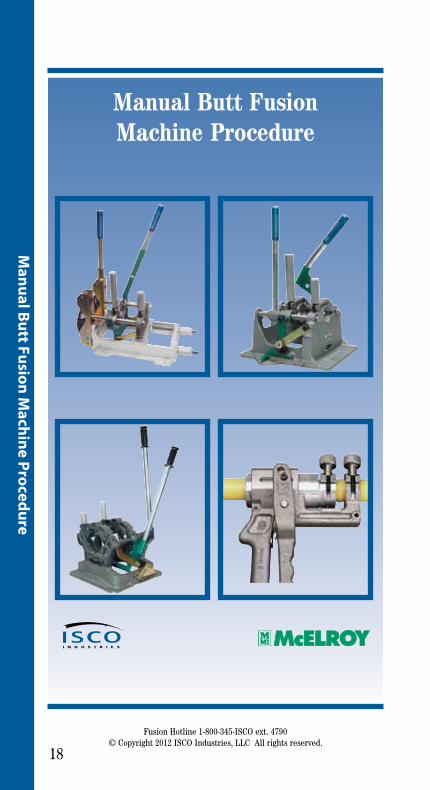
Manual Butt Fusion Machine Procedure
Manual Butt Fusion M
achine Procedure
Fusion Hotline 1-800-345-ISCO ext. 4790© Copyright 2012 ISCO Industries, LLC All rights reserved.
19
Man
ual B
utt F
usio
n M
achi
ne P
roce
dure
Manual Butt Fusion Machine ProcedureThe principle of heat fusion is to heat two surfaces to a designated tempera-ture, and then fuse them together by application of force. This pressure causes flow of the melted materials, which causes mixing and thus fusion. When the polyethylene material is heated, the molecular structure is transformed from a crystalline state into an amorphous condition. When fusion pressure is applied, the molecules from each polyethylene part mix. As the joint cools, the molecules return to their crystalline form, the original interfaces are gone, and the two pipes become one homogeneous unit.
The principle operations include:
Clamping The pipe pieces held axially to allow all subsequent operations to take place.
Facing The pipe ends must be faced to establish clean, parallel mat ing surfaces perpendicular to the centerline of the pipes.
Alignment The pipe ends must be aligned with each other to minimize mismatch or high-low of the pipe wall.
Heating A melt pattern that penetrates into the pipe must be formed around both pipe ends.
Joining The melt patterns must be joined with a specified force. The force must be constant around the interface area.
Holding The molten joint must be held immobile with a specified force until adequately cooled.
ISCO Fusion Manual
Fusion Hotline 1-800-345-ISCO ext. 4790© Copyright 2012 ISCO Industries, LLC All rights reserved.
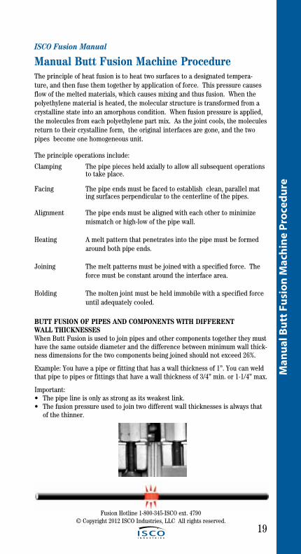
BUTT FUSION OF PIPES AND COMPONENTS WITH DIFFERENT WALL THICKNESSESWhen Butt Fusion is used to join pipes and other components together they must have the same outside diameter and the difference between minimum wall thick-ness dimensions for the two components being joined should not exceed 26%.
Example: You have a pipe or fitting that has a wall thickness of 1”. You can weld that pipe to pipes or fittings that have a wall thickness of 3/4” min. or 1-1/4” max.
Important:• Thepipelineisonlyasstrongasitsweakestlink.• Thefusionpressureusedtojointwodifferentwallthicknessesisalwaysthat of the thinner.

ISCO Fusion Manual
20
Manual Butt Fusion M
achine Procedure
Fusion Hotline 1-800-345-ISCO ext. 4790© Copyright 2012 ISCO Industries, LLC All rights reserved.
Install Clamping Inserts
Select and install appropriate clamping inserts for the pipe that is being fused.
No. 2LC & No. 2CU machines (1/2” CTS - 2” IPS Pipe) 1-1/2” and smaller inserts are fitted to jaw castings using flat head fasteners.
No. 14 Pitbull Machines (1” IPS - 4” DIPS Pipe) 2” Master, 3” & 4” inserts are held in place by spring pins located on upper and lower jaws. 1-1/2” and smaller inserts are fitted to 2” IPS Master inserts using flat head fasteners.
Manual Butt Fusion Machine Procedure
Loading Pipe Into Machine (No. 14 Pitbull Used In the Following Illustrations)
Clean the inside and outside of the pipeends that are to be fused.
Open the upper jaws and insert pipe in each pair of jaws with applicable inserts installed.
Let the ends of the pipe protrude about 1” past the face of the jaws.
Close upper jaws but do not overtighten.
ISCO Fusion Manual
21
Man
ual B
utt F
usio
n M
achi
ne P
roce
dure
Fusion Hotline 1-800-345-ISCO ext. 4790© Copyright 2012 ISCO Industries, LLC All rights reserved.
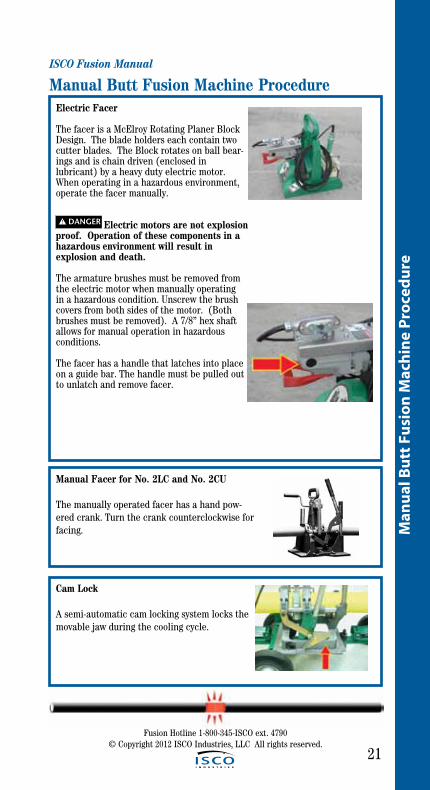
Electric Facer
The facer is a McElroy Rotating Planer Block Design. The blade holders each contain two cutter blades. The Block rotates on ball bear-ings and is chain driven (enclosed in lubricant) by a heavy duty electric motor. When operating in a hazardous environment, operate the facer manually.
Electric motors are not explosionproof. Operation of these components in a hazardous environment will result in explosion and death.
The armature brushes must be removed from the electric motor when manually operating in a hazardous condition. Unscrew the brush covers from both sides of the motor. (Bothbrushes must be removed). A 7/8” hex shaft allows for manual operation in hazardous conditions.
The facer has a handle that latches into place on a guide bar. The handle must be pulled out to unlatch and remove facer.
Manual Butt Fusion Machine Procedure
! DANGER
Manual Facer for No. 2LC and No. 2CU
The manually operated facer has a hand pow-ered crank. Turn the crank counterclockwise for facing.
Cam Lock
A semi-automatic cam locking system locks the movable jaw during the cooling cycle.
ISCO Fusion Manual
22Fusion Hotline 1-800-345-ISCO ext. 4790
© Copyright 2012 ISCO Industries, LLC All rights reserved.
Manual Butt Fusion M
achine Procedure
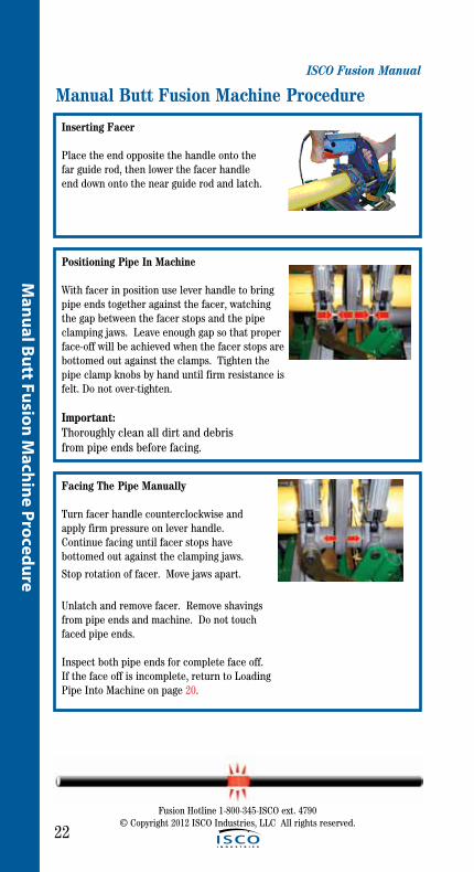
Inserting Facer
Place the end opposite the handle onto the far guide rod, then lower the facer handle end down onto the near guide rod and latch.
Positioning Pipe In Machine
With facer in position use lever handle to bring pipe ends together against the facer, watching the gap between the facer stops and the pipe clamping jaws. Leave enough gap so that proper face-off will be achieved when the facer stops are bottomed out against the clamps. Tighten the pipe clamp knobs by hand until firm resistance is felt. Do not over-tighten.
Important:Thoroughly clean all dirt and debris from pipe ends before facing.
Manual Butt Fusion Machine Procedure
Facing The Pipe Manually
Turn facer handle counterclockwise and apply firm pressure on lever handle. Continue facing until facer stops havebottomed out against the clamping jaws.
Stop rotation of facer. Move jaws apart.
Unlatch and remove facer. Remove shavings from pipe ends and machine. Do not touch faced pipe ends.
Inspect both pipe ends for complete face off. If the face off is incomplete, return to Loading Pipe Into Machine on page 20.

ISCO Fusion Manual
23
Man
ual B
utt F
usio
n M
achi
ne P
roce
dure
Fusion Hotline 1-800-345-ISCO ext. 4790© Copyright 2012 ISCO Industries, LLC All rights reserved.
Electric Facer
The electric facer should be startedbefore the pipe is pushed into contact with the blades.
Continue facing until the facer stops areagainst the jaws.
Turn off the facer while continuing to hold pressure closed on the lever until the facer stops completely.
Reverse force to the lever handle to move the pipe ends away from the facer. Unlatch and remove the facer taking care not to touch the pipe ends.
Remove shavings from pipe ends and machine. Do not touch faced pipe ends as this may contaminate them.
If faced pipe ends are touched, use a clean white nonsynthetic cloth to clean affected area before proceeding.
If after facing, any imperfections are visible, return to Loading Pipe Into Machine on page 20.
Any time clamp knobs are tightened, pipe ends should be refaced.
Manual Butt Fusion Machine Procedure
ISCO Fusion Manual
24Fusion Hotline 1-800-345-ISCO ext. 4790
© Copyright 2012 ISCO Industries, LLC All rights reserved.
Manual Butt Fusion M
achine Procedure
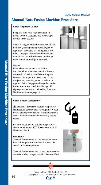
Check Alignment Of Pipe
Bring the pipe ends together under suf-ficient force to overcome any pipe drag or friction in the system.
Check for alignment and proper face off. If high/low (misalignment) exists, adjust by tightening the clamp on the high side and reface the pipes. Their should be no more than 10% of the wall thickness in misalign-ment to maintain full joint strength.
Notice: When clamping, do not over-tighten the clamp knobs because machine damagecan result. Check to see if there is space between the upper and lower jaws. If the two jaws are touching, do not continue to tighten. Bring the pipe ends together under fusion pressure to check for slippage. If slippage occurs, return to Loading Pipe Into Machine section on page 20.
Manual Butt Fusion Machine Procedure
Check Heater Temperature
Incorrect heating temperature can result in questionable fusion joints. Check heater plates periodically in multiple locations with a pyrometer and make necessary adjust-ments.
For butt fusion heater surface temperature should be Minimum 400° F, Optimum 425° F, Maximum 450° F.
Important: The dial thermometer on the heater indicates internal temperature which varies from the actual surface temperature.
The dial thermometer can be used as reference once the surface temperature has been verified.
CAUTION!
ISCO Fusion Manual
25
Man
ual B
utt F
usio
n M
achi
ne P
roce
dure
Fusion Hotline 1-800-345-ISCO ext. 4790© Copyright 2012 ISCO Industries, LLC All rights reserved.
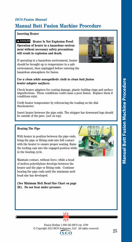
Inserting Heater
Heater Is Not Explosion Proof. Operation of heater in a hazardous environ-ment without necessary safety precautions will result in explosion and death.
If operating in a hazardous environment, heater should be brought up to temperature in a safe environment, then unplugged before entering the hazardous atmosphere for fusion.
Use a clean white nonsynthetic cloth to clean butt fusion heater adapter surfaces.
Check heater adapters for coating damage, plastic buildup rings and surface imperfections. These conditions could cause a poor fusion. Replace them if conditions exist.
Verify heater temperature by referencing the reading on the dial thermometer.
Insert heater between the pipe ends. The stripper bar downward legs should be outside of the jaws. (not on top)
Manual Butt Fusion Machine Procedure
! DANGER
Heating The Pipe
With heater in position between the pipe ends, bring the pipe or fitting ends into full contact with the heater to ensure proper seating. Raise the locking cam into the engaged position while in the heating cycle.
Maintain contact, without force, while a bead of molten polyethylene develops between the heater and the pipe or fitting ends. Continue heating the pipe ends until the minimum melt bead size has developed.
(See Minimum Melt Bead Size Chart on page 26). Do not heat under pressure.
ISCO Fusion Manual
26Fusion Hotline 1-800-345-ISCO ext. 4790
© Copyright 2012 ISCO Industries, LLC All rights reserved.
Manual Butt Fusion M
achine Procedure
Minimum Melt Bead Size (Pipe Ends):
Pipe (OD), in. (mm) Minimum Bead Size in. (mm)
< 2.37 (60) 1/32” (1)
> 2.37 (60) < 3.5 (89) 1/16” (1.5)
> 3.5 (89) < 6.62 (160) 3/16” (5)
Manual Butt Fusion Machine Procedure
Fusing the Pipe
Once melt beads are of proper size, remove the heater, QUICKLY inspect the melted ends, which should be flat, smooth, and completely melted. If the melted surfaces are acceptable, immediately and in a continuous motion, bring the ends together and apply enough joining force for the beads to touch, and form a double roll back against the pipe wall. Do not slam.
A concave melt surface is unacceptable; it indicates pressure during heating. Do not continue. Allow the melted ends to cool and start over.
The locking cams will assist by holding force during the cooling cycle.
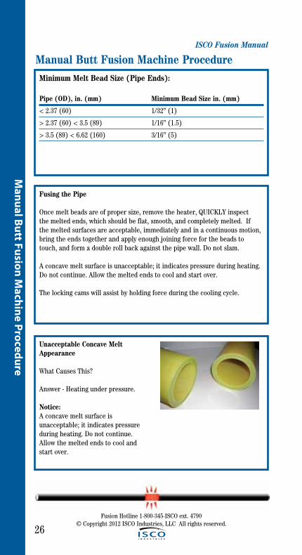
Unacceptable Concave Melt Appearance
What Causes This?
Answer - Heating under pressure.
Notice:A concave melt surface is unacceptable; it indicates pressure during heating. Do not continue. Allow the melted ends to cool andstart over.

ISCO Fusion Manual
27
Man
ual B
utt F
usio
n M
achi
ne P
roce
dure
Fusion Hotline 1-800-345-ISCO ext. 4790© Copyright 2012 ISCO Industries, LLC All rights reserved.
Manual Butt Fusion Machine ProcedureOptional Use Of Torque Wrench
After the heating cycle is completed, remove the heater and quickly apply fusion force with the lever handle. To use a torque wrench with the No. 14 Pitbull, place an adapter in the lever socket.
15” torque wrench is required when using the torque wrench adapter.
The locking cams will assist by holding force during the cooling cycle.
Failure to follow the proper heating time, pressure and cooling time may result in a bad joint.
TorqueWrench Reading(Ft. Lb.)
No. 2LCJaw Axial
Force(Lb.)
No. 14 Pitbull
Jaw Axial Force(Lb.)
No. 26 PitBull
Jaw Axial Force (Lb.)
10 70 115 115
20 135 215 215
30 200 330 330
40 260 435 435
50 320 545 545
60 400 660 660
70 480 780 780
80 550 915 915
90 635 1025 1025
100 690 1140 1140
CAUTION!
Interfacial Pressure (IFP)Minimum 60 psiOptimum 75 psi Maximum 90 psi
To determine the amount of force required: (OD-t) x t x 3.1416 x (IFP) 75 +DRAG = Force
This value is then read on chart to determine how much torque is needed to apply the force.
Drag=Amount of force required to move pipe; measured by torque wrench.
P/N 410802Required

ISCO Fusion Manual
28
Manual Butt Fusion M
achine Procedure
Fusion Hotline 1-800-345-ISCO ext. 4790© Copyright 2012 ISCO Industries, LLC All rights reserved.
Cooling Of The Fusion Joint
Hold the molten joint immobile under fusion pressure until sufficiently cooled. Cooling under pressure before removal from the butt fusion machine is important in achieving joint integrity. Maintain fusion pressure against the piping component ends for a minimum of 11 minutes per inch of pipe wall. Avoid high stress such as pulling, installation or rough for additional 30 min or more after removal from fusion machine.
Manual Butt Fusion Machine Procedure
Remove Pipe and Inspect
After pipe has cooled sufficiently, apply closing force on the lever handle and push the locking cams down into the unlocked position. Unscrew the clamp knobs enough that they can be swiveled outward.
Pull pipe through machine, and prepare for making next fusion. Inspect joint and if it has to be redone, use Trouble Shooting Guides to determine problem and make adjustments before next fusion.(See pages 29 and 30)
Minimum Cooling Time Chart
IPS Pipe DR MCT IPS Pipe DR MCT IPS Pipe DR MCT
2 7.3 4 3 7.3 5 4 7.3 7
2 9 4 3 9 4 4 9 6
2 11 2 3 11 4 4 11 5
2 13.5 2 3 13.5 3 4 13.5 4
3 17 2 4 17 3
5 7.3 8 6 7.3 10
5 9 7 6 9 8
5 11 6 6 11 7
5 13.5 5 6 13.5 5
5 17 4 6 17 4
29
Man
ual B
utt F
usio
n M
achi
ne P
roce
dure
ISCO Fusion Manual
Manual Butt Fusion Machine Procedure
Fusion Hotline 1-800-345-ISCO ext. 4790© Copyright 2012 ISCO Industries, LLC All rights reserved.
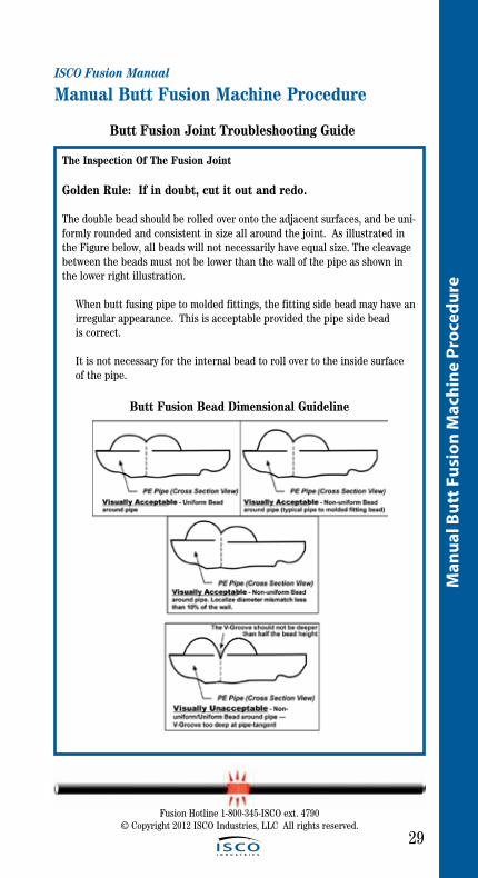
The Inspection Of The Fusion Joint
Golden Rule: If in doubt, cut it out and redo.
The double bead should be rolled over onto the adjacent surfaces, and be uni-formly rounded and consistent in size all around the joint. As illustrated in the Figure below, all beads will not necessarily have equal size. The cleavage between the beads must not be lower than the wall of the pipe as shown in the lower right illustration.
When butt fusing pipe to molded fittings, the fitting side bead may have an irregular appearance. This is acceptable provided the pipe side bead is correct.
It is not necessary for the internal bead to roll over to the inside surface of the pipe.
Butt Fusion Bead Dimensional Guideline
Butt Fusion Joint Troubleshooting Guide
ISCO Fusion Manual
30
Manual Butt Fusion M
achine Procedure
Fusion Hotline 1-800-345-ISCO ext. 4790© Copyright 2012 ISCO Industries, LLC All rights reserved.
Manual Butt Fusion Machine Procedure
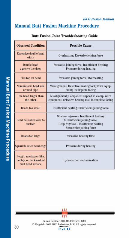
Observed Condition Possible Cause
Excessive double bead width
Overheating; Excessive joining force
Double bead v-groove too deep
Excessive joining force; Insufficient heating; Pressure during heating
Flat top on bead Excessive joining force; Overheating
Non-uniform bead size around pipe
Misalignment; Defective heating tool; Worn equip-ment; Incomplete facing
One bead larger than the other
Misalignment; Component slipped in clamp; worn equipment; defective heating tool; incomplete facing
Beads too small Insufficient heating; Insufficient joining force
Bead not rolled over to surface
Shallow v-groove - Insufficient heating & insufficient joining force;
Deep v-groove - Insufficient heating & excessive joining force
Beads too large Excessive heating time
Squarish outer bead edge Pressure during heating
Rough, sandpaper-like, bubbly, or pockmarked
melt bead surfaceHydrocarbon contamination
Butt Fusion Joint Troubleshooting Guide
31
Man
ual B
utt F
usio
n M
achi
ne P
roce
dure
ISCO Fusion Manual
Manual Butt Fusion Machine Procedure
Fusion Hotline 1-800-345-ISCO ext. 4790© Copyright 2012 ISCO Industries, LLC All rights reserved.
Cold Weather and Inclement Weather Procedure
• Wind and Precipitation - Heating tool shall be shielded in insulated con-tainer to prevent excessive heat loss. Shield the pipe fusion area and fusion tools from wind, snow, blowing dust and rain by using a canopy or similar device. Open pipe ends should be covered with plugs or cov-ers to protect the heater from unacceptable temperature variations. Protective measures with auxiliary heating is recommended when tem-peratures are below -4°F (-20°C).
• Pipe and Fitting Surface Preparation – The pipe and fitting surfaces to be “joined” or held in clamps shall be dry and clean and free of ice, frost, snow, dirt, and other contamination. After regular procedure for facing, the surface shall be protected from contamination until joined
• Heating – Check the temperature of the heating tool regularly with a pyrometer or other surface temperature measuring devise. Do not increase heating tool temperature above the specified temperature (450°F - 232°C) setting. Work quickly once pipe and fittings have been separated from the heating tool; so that melt heat loss is minimized, but still take time (no more than 3 seconds) to inspect both melt patterns. When the ambient temperature becomes colder, it will require a longer heating time to develop an indication of melt and the final bead size.
• Pre-Heating – When the ambient temperature is below 3°F (-16°C), the pipe ends shall be pre-heated using a heating blanket or warm air device to elevate the pipe temperature to improve the heating start-ing condition. With pipe mounted in the fusion machine, an alternate method of pre-heating is to stop the pipe ends within .25-.50 inches (6.4-12.7mm) of the heater plate face to allow the pipe ends to warm for 30 seconds to 2 minutes, depending on the pipe size and wall.

ISCO Fusion Manual
Hydraulic Butt Fusion Machine Procedure
32
Hydraulic Butt Fusion M
achine Procedure
Fusion Hotline 1-800-345-ISCO ext. 4790© Copyright 2012 ISCO Industries, LLC All rights reserved.

33
Fusi
on E
quip
men
t Saf
ety
Info
rmat
ion
Fusion Hotline 1-800-345-ISCO ext. 4790© Copyright 2012 ISCO Industries, LLC All rights reserved.
ISCO Fusion Manual
Hydraulic Butt Fusion Machine ProcedureThe principle of heat fusion is to heat two surfaces to a designated temperature, and then fuse them together by application of force. This pressure causes flow of the melted materials, which causes mixing and thus fusion. When the polyethyl-ene material is heated, the molecular structure is transformed from a crystalline state into an amorphous condition. When fusion pressure is applied, the mol-ecules from each polyethylene part mix. As the joint cools, the molecules return to their crystalline form, the original interfaces are gone, and the two pipes have become one homogeneous unit.
The principle operations include:
Clamping The pipe pieces held axially to allow all subsequent operations to take place.
Facing The pipe ends must be faced to establish clean, parallel mating surfaces perpendicular to the centerline of the pipes.
Alignment The pipe ends must be aligned with each other to minimize mismatch or high-low of the pipe wall.
Heating A melt pattern that penetrates into the pipe must be formed around both pipe ends.
Joining The melt patterns must be joined with a specified force. The force must be constant around the interface area.
Holding The molten joint must be held immobile with a specified force until adequately cooled.
BUTT FUSION OF PIPES AND COMPONENTS WITH DIFFERENT WALL THICKNESSESWhen Butt Fusion is used to join pipes and other components together they must have the same outside diameter and the difference between minimum wall thick-ness dimensions for the two components being joined should not exceed 26%.
Example: You have a pipe or fitting that has a wall thickness of 1”. You can weld that pipe to pipes or fittings that have a wall thickness of 3/4” min. or 1-1/4” max.
Important:• Thepipelineisonlyasstrongasitsweakestlink.• Thefusionpressureusedtojointwodifferentwallthicknessesisalwaysthat of the thinner.
ISCO Fusion Manual
34
Hydraulic Butt Fusion M
achine Procedure
Hydraulic Butt Fusion Machine Procedure
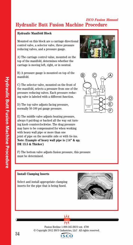
Hydraulic Manifold Block
Mounted on this block are a carriage directional control valve, a selector valve, three pressure reducing valves, and a pressure gauge.
A) The carriage control value, mounted on the top of the manifold, determines whether the carriage is moving left, right, or in neutral.
B) A pressure gauge is mounted on top of the manifold.
C) The selector valve, mounted on the front of the manifold, selects a pressure from one of the pressure reducing valves. Each pressure reduc-ing valve is labeled with a different function.
D) The top valve adjusts facing pressure, normally 50-100 psi gauge pressure.
E) The middle valve adjusts heating pressure,always 0 psi/drag or backed all the way out turn-ing knob counterclockwise. The drag pressure may have to be compensated for when working with heavy wall pipe or more than one joint of pipe on the movable side or with tie-ins. Note: Example of heavy wall pipe is (14” & up; DR 13.5 & Thicker)
F) The bottom valve adjusts fusion pressure, this pressuremust be determined.
FACING
HEATING
FUSING
B C A
DE
F
Install Clamping Inserts
Select and install appropriate clamping inserts for the pipe that is being fused.
Fusion Hotline 1-800-345-ISCO ext. 4790© Copyright 2012 ISCO Industries, LLC All rights reserved.

ISCO Fusion Manual
35
Hyd
raul
ic B
utt F
usio
n M
achi
ne P
roce
dure
Fusion Hotline 1-800-345-ISCO ext. 4790© Copyright 2012 ISCO Industries, LLC All rights reserved.
Hydraulic Butt Fusion Machine ProcedureCheck Hydraulic Pressure
The pressure gauge on the manifold block indicates the pressure of the carriage valve. How much pressure depends on the position of the selec- tor valve and the pressure set on the specific pressure reducing valve. With the selector valve up, the facing pressure can be set. It may be nec- essary to adjust the carriage speed, while facing, with the top pressure- reducing valve to control facing speed.
Shift the selector valve to the center position, heating, and set the pres- sure reducing valve at its lowest setting, or the drag pressure, whichever is higher.
With the selector valve in the down position, the fusion pressure can be set.
The fusion pressure can be calculated using the Fusion Pressure Calculator (shown on the next page or by using the formula on the next page, or they can be found in the reference section.)
An approximate 30 psi drag factor should compensate for seal, and pipe drag with one joint of pipe on a pipe stand. If additional lengths of pipe or heavy wall pipe are being moved by the movable jaws, the actual drag pressure should be determined using the following procedure:
After facing the pipe, move the carriage so that the pipe ends are approximately 2” apart.
Shift the carriage control valve to the middle (neutral) position, select the heating mode, and adjust the middle pressure reducing valve to its lowest pressure by turning the valve counterclockwise.
Shift the carriage control valve to the left.
Gradually increase the pressure by turning the heating valve clockwise. Increase the pressure until the carriage moves.
Quickly reduce the heating pressure valve counterclockwise until the carriage is just barely moving.
Record this actual drag pressure.
Take the pressure, determined from the Fusion Pressure Calculator, and add the actual measured drag pressure. This will be the actual fusion pressure to set with the bottom pressure reducing valve. If fusion pressures are used from the reference section, you must subtract 30 psi drag, which is already figured in and then add the actual drag pressure back.
Adjust the middle heating valve to show recorded drag so that pipe ends will stay in contact with heater during heating phase.

ISCO Fusion Manual
36
Hydraulic Butt Fusion M
achine Procedure
Hydraulic Butt Fusion Machine Procedure
Fusion Pressure Calculator
Interfacial Pressure (IFP)Minimum 60 psiOptimum 75 psi Maximum 90 psi
Interfacial Pressure (IFP) = amount of force per sq. inch of the surface area of the pipe end. Interfacial Pressure (IFP) and Fusion machine gauge pressure are not the same.
How to Use the Fusion Pressure Calculator
Step 1: Set DR at Pipe Size.Step 2: Align McElroy Fusion Machine with IFP.Step 3: Read Gauge Pressure at red arrow.Step 4: Add Drag Pressure to gauge pressure.
Determining Fusion Pressure
Variable DefinitionsOD = Outside Diametert = Wall Thicknessπ = 3.1416DR = Dimensional RatioIFP = Recommended Interfacial Pressure (Shown Above)TEPA = Total Effective Piston AreaDRAG = Force Required to Move Pipe
Example:Using a McElroy No. 28 Standard Fusion Machine (High Force, Green Cyl.)Pipe Size = 8” IPSOD of Pipe = 8.625DR of Pipe = 11Recommended Interfacial Pressure = 75 PSIMeasured Drag 30 PSI
Formula: Wall Thicknesst =
TEPA = 4.710 (chosen from the table on page 37)
Gauge Pressure =
Gauge Pressure =
Fusion Hotline 1-800-345-ISCO ext. 4790© Copyright 2012 ISCO Industries, LLC All rights reserved.
+
+
ISCO Fusion Manual
37
Hyd
raul
ic B
utt F
usio
n M
achi
ne P
roce
dure
Fusion Hotline 1-800-345-ISCO ext. 4790© Copyright 2012 ISCO Industries, LLC All rights reserved.
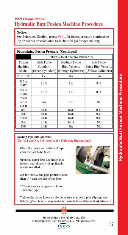
Loading Pipe Into Machine(No. 412 and No. 618 Used In the Following Illustrations)
Clean the inside and outside of pipe ends that are to be fused.
Open the upper jaws and insert pipe in each pair of jaws with applicable inserts installed. Let the ends of the pipe protrude more than 1” * past the face of the jaws.
* This distance changes with fusion machine type.
Tighten the clamp knobs on the outer jaws to prevent pipe slippage and lightly tighten inner clamp knobs for possible later alignment adjustments.
Determining Fusion Pressure (Continued)
Hydraulic Butt Fusion Machine Procedure
TEPA = Total Effective Piston Area
Fusion Machine
Model
High ForceStandard
(Green Cylinders)
Medium ForceHigh Velocity
(Orange Cylinders)
Low ForceExtra High Velocity( Yellow Cylinders)
28 or T-28 4.71 NA 1.67
412 or T-412
11.78 6.01 3.14
618 or T-618
11.78 6.01 3.14
T-500 SeriesI or II
NA 6.01 NA
824 29.44 15.32 9.451236 29.44 15.32 9.45T-900 29.44 15.32 9.451648 31.42 14.14 NA2065 31.42 NA NA
Notice: See Reference Section, pages 86-91, for fusion pressure charts show-ing pressures precalculated to include 30 psi for system drag.
ISCO Fusion Manual
38
Hydraulic Butt Fusion M
achine Procedure
Hydraulic Butt Fusion Machine Procedure
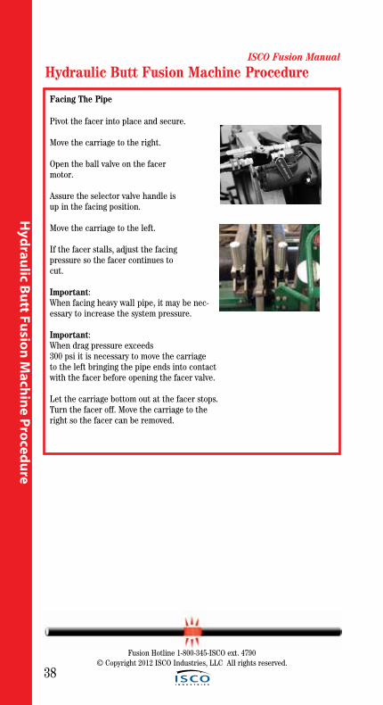
Facing The Pipe
Pivot the facer into place and secure.
Move the carriage to the right.
Open the ball valve on the facer motor.
Assure the selector valve handle is up in the facing position.
Move the carriage to the left.
If the facer stalls, adjust the facing pressure so the facer continues to cut.
Important: When facing heavy wall pipe, it may be nec-essary to increase the system pressure.
Important: When drag pressure exceeds300 psi it is necessary to move the carriageto the left bringing the pipe ends into contact with the facer before opening the facer valve.
Let the carriage bottom out at the facer stops. Turn the facer off. Move the carriage to the right so the facer can be removed.
Fusion Hotline 1-800-345-ISCO ext. 4790© Copyright 2012 ISCO Industries, LLC All rights reserved.

ISCO Fusion Manual
39
Fusion Hotline 1-800-345-ISCO ext. 4790© Copyright 2012 ISCO Industries, LLC All rights reserved.
Hyd
raul
ic B
utt F
usio
n M
achi
ne P
roce
dure
Remove Facer
Pivot the facer out to the storage position.
Remove pipe shavings from lower side of pipe ends, careful not to touch faced pipe ends.
If faced pipe ends are touched, use clean non-synthetic cloth to clean affected area before proceeding.
Move the carriage to the left untilends of pipe butt together. Check pipe joint for proper alignment.
Do not use finger to check for hi/low (misalignment). The unit is under pressure, and slippage could result in crushed fingers. Always keep hands clear of the jaw area.
If pipe is not lined up, tighten the inner high side jaw to bring into alignment.
Important: Always tighten the side that is higher, never loosen the low side.
When the pipe is properly aligned tighten outside clamps to insure against slippage.
If clamp knob adjustment has been made,reinstall facer and begin facing procedure again.
Let the carriage bottom out on facer stops. Turn facer off. Move the carriage to the rightso the facer can be removed.
Remove shavings from pipe ends careful not to touch faced pipe ends.
Bring the pipe ends together under fusion pressure to check for slippage. If slippageoccurs, return to Loading Pipe Into Machine on page 37.
Notice:Their should be no more than 10% of the wall thickness in misalignment to maintain full joint strength.
Hydraulic Butt Fusion Machine Procedure
WARNING!

ISCO Fusion Manual
40
Hydraulic Butt Fusion M
achine Procedure
Check Heater Temperature
Incorrect heating temperature can result in questionable fusion joints. Check heater plates periodically in multiple locations on both sides of plates with a pyrometer and make necessary adjustments.
For butt fusion heater surface temperature should be Minimum 400° F, Optimum 425° F, Maximum 450° F.
Important: The dial thermometer on the heater indicates internal temperature. The dial thermometer can be used as reference once the surface temperature has been verified.
Position Carriage For Heater Insertion
Move carriage to the right to open a gap large enough to insert the heater.
Hydraulic Butt Fusion Machine Procedure
CAUTION!
FACING
HEATING
FUSING
Select the Fusion Position
Move selector valve handle down to the fusing position. Use fusion pressure required from Fusion Pressure Calculator or the formula on page 36 . Also see Reference Section, page 86-91.
FACING
HEATING
FUSING
Fusion Hotline 1-800-345-ISCO ext. 4790© Copyright 2012 ISCO Industries, LLC All rights reserved.

ISCO Fusion Manual
41
Hyd
raul
ic B
utt F
usio
n M
achi
ne P
roce
dure
Fusion Hotline 1-800-345-ISCO ext. 4790© Copyright 2012 ISCO Industries, LLC All rights reserved.
Heating The Pipe
A) Move the carriage to the left under the fusion pressure, bring-ing the heater into full contact with both pipe ends, seating pipe ends against heater. Briefly ensure full contact between piping component ends and heating tool and then reduce the pressure to drag without breaking contact. On Larger pipe sizes, (14in. and larger) maintain the fusion pressure until a slight melt is observed around the circumference of the pipe or fitting before reducing pressure. Once the indication of melt is observed around the cir-cumference of each pipe then move to step B.
B) Move selector valve to center position, allowing the pressure to drop but maintaining contact without force. When fusing more than one pipe length on the movable side of the fusion unit, drag must be compensated for as described on pg 35.
Inserting Heater
Heater is Not Explosion Proof. Operation of heater in a hazardous environment without necessary safety precautions could result in explosion and death.
If operating in a hazardous environ ment, heater should be brought up to temperature in a safe environment,then unplugged before entering the hazardous atmosphere for fusion.
Use a clean white non-synthetic cloth to clean the butt fusion heater adapter surfaces.
Check heater plates for coating damage, plastic buildup rings and surface imperfec-tions. These conditions could cause a poor fusion. Replace them if conditions exist.
Verify heater temperature noting the reading on the dial thermometer.
Insert heater between the pipe ends.
Hydraulic Butt Fusion Machine Procedure
! DANGER
FACING
HEATING
FUSING
A
FACING
HEATING
FUSING
B
FACING
HEATING
FUSING
C

ISCO Fusion Manual
42
Hydraulic Butt Fusion M
achine Procedure
Fusion Hotline 1-800-345-ISCO ext. 4790© Copyright 2012 ISCO Industries, LLC All rights reserved.
Hydraulic Butt Fusion Machine Procedure
Heating The Pipe
C) Return carriage control valve to neutral (middle) position. The pipe ends are now heating at “0” pressure or the pressure to compensate for drag, allowing the pipe ends to remain in full contact with the heater, while a bead of molten polyethyl-ene develops between the heater and the pipe or fitting ends. For 14” IPS pipe sizes and larger, maintain the heat soak time for a minimum of 4.5 minutes for every inch (25.4mm) of pipe wall thickness. (see Minimum Heat Soak Time & Cooling Time Table pg 45) After the minimum heat soak time for larger pipe sizes and for all other pipe sizes; verify the minimum bead size has been established, using the Minimum Melt Bead Size table to determine the proper size, then:
FACING
HEATING
FUSING
A
FACING
HEATING
FUSING
B
FACING
HEATING
FUSING
C
Minimum Melt Bead Size (Pipe Ends)
Pipe (OD) ( Outside Diameter, in. (mm)) Approximate
Melt Bead Size Below 2” IPS (60) - 1/32”
Above 2" (60)through 3"(89) - 1/16" Above 3"(89) through 8" (219) - 3/16"
Above 8"(219) through 12"(324) - 1/4" Above 12"(324) through 24"(610) – 3/8"
Above 24"(610) through 36"(900) - 7/16" Above 36"(900) through 65”(1625) - 9/16"
Hyd
raul
ic B
utt F
usio
n M
achi
ne P
roce
dure
ISCO Fusion Manual
43
Fusion Hotline 1-800-345-ISCO ext. 4790© Copyright 2012 ISCO Industries, LLC All rights reserved.
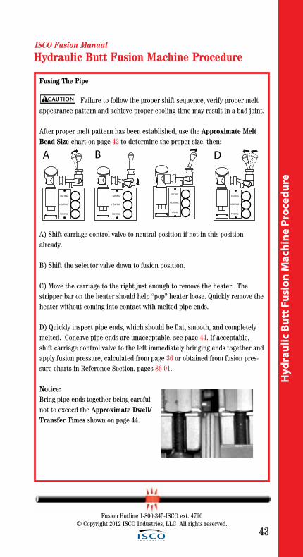
Fusing The Pipe
Failure to follow the proper shift sequence, verify proper melt appearance pattern and achieve proper cooling time may result in a bad joint.
After proper melt pattern has been established, use the Approximate Melt Bead Size chart on page 42 to determine the proper size, then:
A) Shift carriage control valve to neutral position if not in this position already.
B) Shift the selector valve down to fusion position.
C) Move the carriage to the right just enough to remove the heater. The stripper bar on the heater should help “pop” heater loose. Quickly remove the heater without coming into contact with melted pipe ends.
D) Quickly inspect pipe ends, which should be flat, smooth, and completely melted. Concave pipe ends are unacceptable, see page 44. If acceptable, shift carriage control valve to the left immediately bringing ends together and apply fusion pressure, calculated from page 36 or obtained from fusion pres-sure charts in Reference Section, pages 86-91.
Notice: Bring pipe ends together being careful not to exceed the Approximate Dwell/Transfer Times shown on page 44.
CAUTION!
FACING
HEATING
FUSING
A
FACING
HEATING
FUSING
D
FACING
HEATING
FUSING
FACING
HEATING
FUSING
B
Hydraulic Butt Fusion Machine Procedure

ISCO Fusion Manual
44
Hydraulic Butt Fusion M
achine Procedure
Hydraulic Butt Fusion Machine Procedure
Fusion Hotline 1-800-345-ISCO ext. 4790© Copyright 2012 ISCO Industries, LLC All rights reserved.
Approximate Dwell/Transfer Times
Unacceptable Concave Melt Appearance
What Causes This?
Answer - Heating under pressure.
Notice: A concave melt surface is unacceptable; it indicates pressure during heating. Do not continue. Allow the melted ends to cool andstart over.
Pipe Wall Thickness, in (mm) Max. Transfer Time
½ CTS to 1 ½” IPS - 4 sec. 0.20 to 0.36 (5 to 9) 8 seconds
>0.36 to 0.55 (9 to 14) 10 seconds >0.55 to 1.18 (14 to 30) 15 seconds
>1.18 to 2.5 (30 to 64) 20 seconds > 2.5 to 4.5 (64 to 114) 25 seconds
Cooling Of The Fusion Joint
The fusion joint must be kept under fusion pressure until joint has sufficiently cooled. Maintain fusion pressure against the piping component ends for a minimum of 11 minutes per inch (25.4mm) of pipe wall. (See Minimum Heat Soak Time & Cooling Time Table on pg 45) Avoid high stress such as pull-ing, installation or rough handling for an additional 30 minutes or more after removal from the fusion machine.

Hyd
raul
ic B
utt F
usio
n M
achi
ne P
roce
dure
ISCO Fusion Manual
45
Fusion Hotline 1-800-345-ISCO ext. 4790© Copyright 2012 ISCO Industries, LLC All rights reserved.
Hydraulic Butt Fusion Machine Procedure
IPS PIPE
DR MHST MCT IPS PIPE
DR MHST MCT IPS PIPE
DR MHST MCT
2 7.3 4 14 7.3 9 21 32 9 16 39
2 9 3 14 9 7 17 32 11 13 32
2 11 2 14 11 6 14 32 13.5 11 26
2 13.5 2 14 13.5 5 11 32 17 8 21
3 7.3 5 16 7.3 10 24 34 9 17 42
3 9 4 16 9 8 20 34 11 14 34
3 11 4 16 11 7 16 34 13.5 11 28
3 13.5 3 16 13.5 5 13 34 17 9 22
4 7.3 7 18 7.3 11 27 36 9 18 44
4 9 6 18 9 9 22 36 11 15 36
4 11 5 18 11 7 18 36 13.5 12 29
4 13.5 4 18 13.5 6 15 36 17 10 23
5 7.3 8 20 7.3 12 30 42 11 17 42
5 9 7 20 9 10 24 42 13.5 14 34
5 11 6 20 11 8 20 42 17 11 27
5 13.5 5 20 13.5 7 16 42 21 9 22
6 7.3 10 24 7.3 15 36 48 11 20 48
6 9 8 24 9 12 29 48 13.5 16 39
6 11 7 24 11 10 24 48 17 13 31
6 13.5 5 24 13.5 8 20 48 21 10 25
8 7.3 13 26 9 13 32 54 11 22 54
8 9 11 26 11 11 26 54 13.5 18 44
8 11 9 26 13.5 9 21 54 17 14 35
8 13.5 7 26 17 7 17 54 21 12 28
10 7.3 16 28 9 14 34 63 11 26 63
10 9 13 28 11 11 28 63 13.5 21 51
10 11 11 28 13.5 9 23 63 17 17 41
10 13.5 9 28 17 7 18 63 21 14 33
12 7.3 19 30 9 15 32 65 13.5 22 53
12 9 16 30 11 12 30 65 17 17 42
12 11 13 30 13.5 10 24 65 21 14 34
12 13.5 10 30 17 8 19 65 26 11 28
Minimum Heat Soak Time & Cooling Time Table

ISCO Fusion Manual
46
Hydraulic Butt Fusion M
achine Procedure
Hydraulic Butt Fusion Machine Procedure
Fusion Hotline 1-800-345-ISCO ext. 4790© Copyright 2012 ISCO Industries, LLC All rights reserved.
Opening Movable Jaws
After the joint has cooled for the recom-mended time, shift the carriage controlvalve to the neutral position.
Loosen all clamp knobs, and move carriage to the right far enough to open the jaw nearest the facer.
Open the movable jaws.
Opening Fixed Jaws
Open the fixed jaws
Raise Pipe
Raise the joined pipe using the pipe lift(s).
Pull Pipe through machine, and prepare for making next fusion. Inspect joint and if it has to be redone, use Trouble Shooting Guides on page 47 and 48 to determine problem and make adjustments before nextfusion.

47
ISCO Fusion Manual
Hyd
raul
ic B
utt F
usio
n M
achi
ne P
roce
dure
Fusion Hotline 1-800-345-ISCO ext. 4790© Copyright 2012 ISCO Industries, LLC All rights reserved.
The Inspection Of The Fusion Joint
Golden Rule: If in doubt, cut it out and redo.
The double bead should be rolled over onto the adjacent surfaces, and be uni-formly rounded and consistent in size all around the joint. As illustrated in the Figure below, all beads will not necessarily have equal size. The cleavage between the beads must not be lower than the wall of the pipe as shown in the lower right illustration.
When butt fusing pipe to molded fittings, the fitting side bead may have an irregular appearance. This is acceptable provided the pipe side bead is correct.
It is not necessary for the internal bead to roll over to the inside surface of the pipe.
Butt Fusion Bead Dimensional Guideline
Butt Fusion Joint Troubleshooting Guide
Hydraulic Butt Fusion Machine Procedure

ISCO Fusion Manual
48
Hydraulic Butt Fusion M
achine Procedure
Hydraulic Butt Fusion Machine Procedure
Fusion Hotline 1-800-345-ISCO ext. 4790© Copyright 2012 ISCO Industries, LLC All rights reserved.
What Is Present Attributing Factors
One bead larger than the other
Misalignment, component slipped in clamp, worn equip-
ment, incomplete facing
Bead not rolled over to surface
Shallow v-groove - insufficient heating & insufficient joining force, deep v-groove - insuffi-
cient heating & excessive join-ing force
Squarish outer bead edge Pressure during heating
Excessive double bead widthOverheating, excessive joining
force
Flat top on beadExcessive joining force, over-
heating
Beads too smallInsufficient heating or joining
force
Beads too large Excessive heating time
Rough, sand-paper like, bub-bly, or pockmarked melt
bead surfaceHydrocarbon contamination
Double v-groove too deepExcessive joining force, insuf-
ficient heating, pressure during heating
Non-uniform bead size around pipe
Misalignment, defective heating tool, worn equipment, incom-
plete facing
A third bead Excessive joining force
Butt Fusion Joint Troubleshooting Guide

ISCO Fusion Manual
49
Hyd
raul
ic B
utt F
usio
n M
achi
ne P
roce
dure
Fusion Hotline 1-800-345-ISCO ext. 4790© Copyright 2012 ISCO Industries, LLC All rights reserved.
Position Pipe For Next Joint
Move the fusion machine to the end of pipe, or pull the pipe through the jaws until the end of the pipe is protruding more than 1” * past the jaw face of the fixed jaw.
* This distance changes with fusion machine type.
Install Next Piece Of Pipe
Insert a new piece of pipe in the movable jaws and repeat all previous procedures.
Hydraulic Butt Fusion Machine Procedure
50
ISCO Fusion Manual
Hydraulic Butt Fusion M
achine Procedure
Fusion Hotline 1-800-345-ISCO ext. 4790© Copyright 2012 ISCO Industries, LLC All rights reserved.
Hydraulic Butt Fusion Machine Procedure
Cold Weather and Inclement Weather Procedure
• Wind and Precipitation - Heating tool shall be shielded in insulated con-tainer to prevent excessive heat loss. Shield the pipe fusion area and fusion tools from wind, snow, blowing dust and rain by using a canopy or similar device. Open pipe ends should be covered with plugs or cov-ers to protect the heater from unacceptable temperature variations. Protective measures with auxiliary heating is recommended when tem-peratures are below -4°F (-20°C).
• Pipe and Fitting Surface Preparation – The pipe and fitting surfaces to be “joined” or held in clamps shall be dry and clean and free of ice, frost, snow, dirt, and other contamination. After regular procedure for facing, the surface shall be protected from contamination until joined
• Heating – Check the temperature of the heating tool regularly with a pyrometer or other surface temperature measuring devise. Do not increase heating tool temperature above the specified temperature (450°F - 232°C) setting. Work quickly once pipe and fittings have been separated from the heating tool; so that melt heat loss is minimized, but still take time (no more than 3 seconds) to inspect both melt patterns. When the ambient temperature becomes colder, it will require a longer heating time to develop an indication of melt and the final bead size.
• Pre-Heating – When the ambient temperature is below 3°F (-16°C), the pipe ends shall be pre-heated using a heating blanket or warm air device to elevate the pipe temperature to improve the heating start-ing condition. With pipe mounted in the fusion machine, an alternate method of pre-heating is to stop the pipe ends within .25-.50 inches (6.4-12.7mm) of the heater plate face to allow the pipe ends to warm for 30 seconds to 2 minutes, depending on the pipe size and wall.
51
Sadd
le F
usio
n M
achi
ne P
roce
dure
Fusion Hotline 1-800-345-ISCO ext. 4790© Copyright 2012 ISCO Industries, LLC All rights reserved.
Saddle Fusion Machine Procedure

52
Saddle Fusion Machine Procedure
The theory of heat fusion is to heat two surfaces to a designated temperature, and then fuse them together by appli-cation of force. This pressure causes flow of the melted materials, which causes mixing and thus fusion. When the polyethylene material is heated, the molecular structure is transformed from a crystalline state into an amor-phous condition. When fusion pressure is applied, the molecule from each polyethylene part mix. As the jointcools, the molecules return to their crystalline form, the original interfaces are gone, and the fitting and pipe have become one homogeneous unit.
The principle operations include:
Clamping The pipe and fitting must be held firmly to allow all subsequent operations to take place.
Cleaning The area of pipe that the fitting will come in contact with must be cleaned and roughed up, as well as the base of the fitting.
Alignment The fitting must be properly seated on the pipe and then clamped in the machine for proper alignment.
Heating A melt pattern must be formed that penetrates into the pipe and into the fitting.
Joining The melt patterns must be joined with a specified force. The force must be constant around the interface area.
Holding The molten joint must be held immobile with a specified force until adequately cooled.
Saddle Fusion Machine Procedure
Fusion Hotline 1-800-345-ISCO ext. 4790© Copyright 2012 ISCO Industries, LLC All rights reserved.
ISCO Fusion Manual

ISCO Fusion Manual
53
Sadd
le F
usio
n M
achi
ne P
roce
dure
Fusion Hotline 1-800-345-ISCO ext. 4790© Copyright 2012 ISCO Industries, LLC All rights reserved.
Saddle Fusion Procedures
Initial Heat (Bead-up): The heating step used to develop a melt bead on the main pipe.
Initial Heat Force (Bead-up force): The force (pound) applied to establish a melt pattern on the main pipe. The Initial Heat Force is determined by multiply-ing the fitting base (in.²) area by the initial heat interfacial pressure 60 (LB/in.²). This force is twice the fusion force.
Heat Soak Force: The force (pound) applied after an initial melt pattern is established on the main pipe. The Heat Soak Force is the minimum force (essentially zero pounds) that ensures that the fitting, heater, and main stay in contact with each other.
Fusion Force: The force (pounds) applied to establish the fusion bond between the fitting base and the pipe. The Fusion Force is determined by multiplying the fitting base area (in.²) by the fusion interfacial pressure 30 (LB/in.²).
Fusion Interfacial Pressure: The amount of pressure determined by ASTM F2620 & PPI TR 41 as the optimum for interaction between HDP pipe and saddle base, 30 (Lb/in.²).
Total Heat Time: A time that starts when the heater is placed on the main pipe and initial heat force is applied and ends when the heater is removed.
Cool Time: The time required to cool the joint to approximately 120° F (49° C). The fusion force must be maintained for five minutes on 1-1/4 IPS or ten minutes for all other main sizes, after which the saddle fusion equipment can be removed. The joint must be allowed to cool undisturbed for an additional thirty minutes before tapping the main or joining to the branch outlet.
Interfacial Area for Rectangular Base Fittings: The major width times the major length of the saddle base, without taking into account the curvature of the base or sides, minus the area of the hole in the center of the base.
Interfacial Area for Round Base Fittings: The radius of the saddle base squared times π (3.1416), without taking into account the curvature of the base or sides, minus the area of the hole in the center of the base.
Fitting Label: The Initial Heat Force, Heat Soak Force, and the Fusion Force may be listed in the lower right corner of the fitting label for all saddle fusion fittings. This will eliminate the need to calculate the fusion forces in the field (example 80/0/40). Some manufacturers have this information on fitting labels but not all.
Definitions
ISCO Fusion Manual
54
Saddle Fusion Machine Procedure
Fusion Hotline 1-800-345-ISCO ext. 4790© Copyright 2012 ISCO Industries, LLC All rights reserved.
Saddle Fusion Procedures
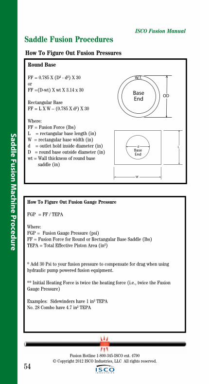
Round Base
FF = 0.785 X (D² - d²) X 30orFF =(D-wt) X wt X 3.14 x 30
Rectangular BaseFF = L X W – (0.785 X d²) X 30
Where:FF = Fusion Force (lbs)L = rectangular base length (in)W = rectangular base width (in)d = outlet hold inside diameter (in)D = round base outside diameter (in)wt = Wall thickness of round base saddle (in)
How To Figure Out Fusion Pressures
OD
W.T.
BaseEnd
How To Figure Out Fusion Gauge Pressure
FGP = FF / TEPA
Where:FGP = Fusion Gauge Pressure (psi)FF = Fusion Force for Round or Rectangular Base Saddle (lbs)TEPA = Total Effective Piston Area (in²)
* Add 30 Psi to your fusion pressure to compensate for drag when using hydraulic pump powered fusion equipment.
** Initial Heating Force is twice the heating force (i.e., twice the Fusion Gauge Pressure)
Examples: Sidewinders have 1 in² TEPANo. 28 Combo have 4.7 in² TEPA
LBaseEnd
W
d

ISCO Fusion Manual
55
Sadd
le F
usio
n M
achi
ne P
roce
dure
Fusion Hotline 1-800-345-ISCO ext. 4790© Copyright 2012 ISCO Industries, LLC All rights reserved.
Prepare Fusion MachineThis procedure requires the use of a Saddle Fusion Tool like the examples shown on the cover page of this pro-cedure. This tool must be capable of holding and supporting the main, rounding the main for good alignment between the pipe and fitting, holding the fitting, applying and indicating the proper force during the fusion process.
Install the Saddle Fusion Tool on the main according to the manufacturer’s instructions. The tool should be cen-tered over a clean, dry location where the fitting will be fused. Secure the tool to the main. A main bolster or support is recommended under the pipe on 6” IPS and smaller main pipe sizes.
Saddle Fusion Procedures
Abrade the fusion surface of the fit-ting with 50 to 60 grit utility cloth; to remove oxidation layer and contami-nants. After abrading, brush residue away with a clean, dry cloth.

ISCO Fusion Manual
56
Saddle Fusion Machine Procedure
Fusion Hotline 1-800-345-ISCO ext. 4790© Copyright 2012 ISCO Industries, LLC All rights reserved.
Insert the fitting in the Saddle Fusion Tool loosely.
Using the Saddle Fusion Tool, move the fitting base and apply about 100 pounds force to seat the fitting. Secure the fitting in the Saddle Fusion Tool.
Saddle Fusion Procedures
Heating Heater is Not Explosion Proof. If working in a hazardous environment review pages 7, 13 and 14 in Safety Section.
Incorrect heating temperature can result in questionable fusion joints. Check heater plates periodically in multiple locations with a pyrometer and make necessary adjustments.
The heater must be fitted with the correct heater adapters. Serrated heater adapters are recommended to allow for maximum heat penetration. The non-stick coating on the heater adapters should be in good condition. The temperature of the heater adapter fusion surfaces must be 490-510º F, with 500ºF being Optimum.
Important:The dial thermometer on the heater indicates internal temperature. The dial thermometer can be used as reference once the surface temperature has been verified.
CAUTION!
Abrade the fusion surface of the main with a 50-60 grit utility cloth to remove oxidation layer and contami-nates. The abraded area must be larger than the area covered by the fitting base. After abrading, brush residue away with a clean, dry cloth.
! DANGER

ISCO Fusion Manual
57
Fusion Hotline 1-800-345-ISCO ext. 4790© Copyright 2012 ISCO Industries, LLC All rights reserved.
Saddle Fusion Machine Procedure
Saddle Fusion Procedures
Heating Procedure For Small Fittings (<2in.IPS) Place the heating tool on the main centered beneath the fitting base. Immediately move the fitting against the heater faces, apply the Initial Heat Force, (see fitting label or use twice the calculated fusion pressure), and start the heat time.
During Heating, Hold the heating tool in position by lightly supporting the heating tool handle. If not supported, the heating tool can slip out of posi-tion or displace the main or fitting melt and result in a poor joint.
Apply the Initial Heat Force until melt is first observed on the crown of the pipe main, (Initial Heat is the term used to describe the initial heating (bead-up) step to develop a melt bead on the main pipe and usually is 3-5 seconds) and then reduce the force to the Heat Soak Force (Bead-up Force) (see fitting label or use “0” psi.) At the end of the Total Heat Time (See Maximum Heating Time and Minimum Cooling Time Table, Page 59), remove the fitting from the heater and the heater from the main with a quick snapping action. Quickly check the melt pattern on the main pipe and fitting base for even melt patterns (no unheated areas).
Installing Fusion Heater Adapters
The heater body of this assembly is not coated. Coated heater adapters are available for all fusion applications.
Heater adapters are installed with Stainless Steel Cap Screws.
Care should be taken to assure that the heater adapters are seat- ed on the heater body, and that there is no foreign matter trapped between these surfaces.
Important: Do not over-tighten the bolts.
The surface of the heater adapt-ers are coated with an anti-stick coating.

ISCO Fusion Manual
58
Fusion Hotline 1-800-345-ISCO ext. 4790© Copyright 2012 ISCO Industries, LLC All rights reserved.
Saddle Fusion Machine Procedure
Saddle Fusion ProceduresHeating Procedure For Large Fittings (>IPS 3in) and Large Mains (>IPS 6in.)
Place the heating tool on the main centered beneath the fitting base while supporting the heating tool handle, and then place the flexible Shield between the heating tool and the fitting base. (This step could require an assistant to handle the Flexible Heat Shield).
Move the fitting against the Flexible Heat Shield, apply Initial Heat Force, and observe melt bead formation on the main all around the heating tool faces.
When a melt is first visible on the main all around the heating tool faces, in a quick continuous motion, release the Initial Heat Force, raise the fitting slightly, remove the Flexible Heat Shield, move the fitting against the heating tool face, apply Initial Heat Force and start the heat time.
When a melt bead is first visible all around the fitting base (usually about 3 to 5 s) immediately reduce applied force to the Heat Soak Force (usually zero). Maintain the Heat Soak Force until the Total Heat Time ends (See Maximum Heating Time And Minimum Cooling Time Table, Page 59).
At the end of the Total Heat Time, remove the fitting from the heater and the heater from the main with a quick snapping action. Quickly check the melt pattern on the main pipe and fitting base for even melt patterns (no unheated areas).
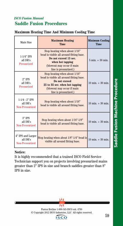
ISCO Fusion Manual
59
Sadd
le F
usio
n M
achi
ne P
roce
dure
Fusion Hotline 1-800-345-ISCO ext. 4790© Copyright 2012 ISCO Industries, LLC All rights reserved.
Saddle Fusion Procedures
Main SizeMaximum Heating
TimeMinimum Cooling
Time
1-1/4” IPS all DR’s
Pressurized
Stop heating when about 1/16” bead is visible all around fitting base.
Do not exceed 15 sec. when hot tapping
(blowout may occur if main line is pressurized.)
5 min. + 30 min.
2” IPS all DR’s
Pressurized
Stop heating when about 1/16” bead is visible all around fitting base.
Do not exceed 25 to 35 sec. when hot tapping
(blowout may occur if main line is pressurized.)
10 min. + 30 min.
1-1/4 - 2” IPS all DR’s
Non-Pressurized
Stop heating when about 1/16” bead is visible all around fitting base.
10 min. + 30 min.
3” IPS all DR’s
Non-Pressurized
Stop heating when about 1/16”-1/8” bead is visible all around fitting base.
10 min. + 30 min.
4” IPS and Larger all DR’s
Non-Pressurized
Stop heating when about 1/8”-1/4” bead is visible all around fitting base.
10 min. + 30 min.
Maximum Heating Time And Minimum Cooling Time
Notice:It is highly recommended that a trained ISCO Field Service Technician support you on projects involving pressurized mains greater than 2” IPS in size and branch saddles greater than 8” IPS in size.

ISCO Fusion Manual
60
Fusion Hotline 1-800-345-ISCO ext. 4790© Copyright 2012 ISCO Industries, LLC All rights reserved.
Saddle Fusion Machine Procedure
Saddle Fusion Procedures
Fusion and CoolingWhether or not the melt patterns are satisfactory, press the fitting onto the main pipe very quickly (within 3 sec-onds) after removing the heater and apply the Fusion Force (See the fitting label or use the formula on page 54 to calculate). Maintain the Fusion Force on the assembly for 5 minutes on 1-1/4” IPS mains and for 10 minutes on all larger sizes , after which the saddle fusion equipment may be removed. (Fusion Force adjustment may be required during Cooling Time, but never reduce the Fusion Force during the cooling). Important: Visually check the fusion bead around the entire fitting base at the main pipe. The fusion bead should be uniformly sized all around the fitting base, and should have a characteristic “three-bead” shape. The first bead is the fitting base melt bead. The second or outer-most bead is produced by the edge of the heating tool face on the main. The third or center bead is the main pipe melt bead. The first and third beads should be about the same 1/8” - 1/4” size all around the fitting base. The second bead is usually smaller, but should also be uniformly sized around the fitting base.
The assembly should cool for an addi-tional 30 minutes before rough handling or tapping the main. Inspect fusion using the troubleshooting guide on page 61 for proper melt patterns. If melt pat-terns are not satisfactory or if the fusion bead is unacceptable, cut off the saddle fitting above the base to prevent use and relocate to a new section of main. Then make a new saddle fusion using a new fitting. Important: These procedures are based on tests conducted under controlled ambient temperature conditions. Environmental conditions on a job site could affect heating and cooling times. Regardless of job site conditions or ambient tempera-ture, the prescribed heating tool tem-perature is required. Do not increase or decrease the heating tool temperature.

ISCO Fusion Manual
61
Sadd
le F
usio
n M
achi
ne P
roce
dure
Fusion Hotline 1-800-345-ISCO ext. 4790© Copyright 2012 ISCO Industries, LLC All rights reserved.
Saddle Fusion Procedures
Observed Condition Possible Cause
Non-uniform bead size around fitting base
Misalignment; Defective heating tool; Loose or contaminated heating tool saddle faces;
Worn equipment; Fitting not secured in application tool; Heating tool faces not within
specified temperature
One bead larger than the other
Misalignment; Component slipped in clamp; Worn equipment; Defective heating tool;
Loose or contaminated heating tool saddle faces; Heating tool faces not within specified
temperature
Beads too smallInsufficient heating;
Insufficient joining force
Beads too large Excessive heating time; Excessive force
No third bead, or third bead widely separated
from center bead
Incorrect pipe main heating tool face or insufficient joining force
Serrated bead appearance Normal for serrated heating tool faces
Smooth bead appearance Normal for smooth heating tool faces
Pressurized main pipe blowout (beside base or through
fitting center)
Overheating; Incorrect heating tool faces; Heating tool faces not within specified
temperature; Taking too much time to start heating or to remove the heating tool and
join the fitting to the main pipe
Rough, sandpaper-like, bubbly, or pockmarked
melt bead surfaceHydrocarbon contamination
Troubleshooting Guide

ISCO Fusion Manual
62
Saddle Fusion Machine Procedure
Fusion Hotline 1-800-345-ISCO ext. 4790© Copyright 2012 ISCO Industries, LLC All rights reserved.
Saddle Fusion Procedures
Cold Weather and Incement Weather Procedure
• Wind and Precipitation - Heating tool shall be shielded in insulated con-tainer to prevent excessive heat loss. Shield the pipe fusion area and fusion tools from wind, snow, blowing dust and rain by using a canopy or similar device. Open pipe ends should be covered with plugs or cov-ers to protect the heater from unacceptable temperature variations. Protective measures with auxiliary heating is recommended when tem-peratures are below -4°F (-20°C).
• Pipe and Fitting Surface Preparation – The pipe and fitting surfaces to be “joined” or held in clamps shall be dry and clean and free of ice, frost, snow, dirt, and other contamination. After regular procedure for facing, the surface shall be protected from contamination until joined
• Heating – Check the temperature of the heating tool regularly with a pyrometer or other surface temperature measuring devise. Do not increase heating tool temperature above the specified temperature (510°F - 266°C) setting. Work quickly once pipe and fittings have been separated from the heating tool; so that melt heat loss is minimized, but still take time (no more than 3 seconds) to inspect both melt patterns. When the ambient temperature becomes colder, it will require a longer heating time to develop an indication of melt and the final bead size.
• Pre-Heating – When the ambient temperature is below 3°F (-16°C), the pipe ends shall be pre-heated using a heating blanket or warm air device to elevate the pipe temperature to improve the heating starting condition.

ISCO Fusion Manual
63
Sadd
le F
usio
n M
achi
ne P
roce
dure
Fusion Hotline 1-800-345-ISCO ext. 4790© Copyright 2012 ISCO Industries, LLC All rights reserved.
Saddle Fusion Procedures
FusionWidth
4 - Convex (Large Round Base)
FusionWidth
2 - Convex (Rectangular Base)
FusionWidth
0 - Convex (Small Round Base)
Heater Adapter Code System
S 2 0 0 2 3 7 3 0 0
Heater Size (2”or 4”)
Serrated Face(Drop for Smooth Face)
Pipe OD (i.e. 2.37”)Fusion Widthof Adapter (i.e. 3.00”)
0 - Convex (Small Round Base)1 - Concave (Small Round Base)2 - Convex (Rectangular Base)3 - Concave (Rectangular Base)4 - Convex (Large Round Base)5 - Concave (Large Round Base)
FusionWidth
1 - Concave (Small Round Base)
FusionWidth
3 - Concave (Rectangular Base)
FusionWidth
3 - Concave (Rectangular Base)
FusionWidth
5 - Concave (Large Round Base)
Heater Adapter Code System
0-Convex (Small Round Base) 1-Concave (Small Round Base)2-Convex (Rectangular Base)3-Concave (Rectangular Base)4-Convex (Large Round Base)5-Concave (Large Round Base)
Serrated Face (Drop for Smooth Face)
S 2 0 0237 300
Heater Size (2” or 4”) Pipe OD (i.e. 2.37”)
Fusion Width of Adapter (i.e. 3.00”)

64
ISCO Fusion Manual
FusionWidth
1 - Concave (Small Round Base)
FusionWidth
3 - Concave (Rectangular Base)
FusionWidth
3 - Concave (Rectangular Base)
FusionWidth
5 - Concave (Large Round Base)
Fusion Hotline 1-800-345-ISCO ext. 4790© Copyright 2012 ISCO Industries, LLC All rights reserved.
Saddle Fusion Machine Procedure
Saddle Fusion Procedures

65
Sock
et T
oolin
g an
d Fu
sion
Pro
cedu
re
Fusion Hotline 1-800-345-ISCO ext. 4790© Copyright 2012 ISCO Industries, LLC All rights reserved.
Socket Tooling and Fusion Procedure
Nomenclature
1) Heater Sling 2) Heater 3) Chamfer Tool/Depth Gauge 4) Heater Adapters 5) Pipe Cutter 6) Clean Cloth 7) Fitting Holder 8) Cold Ring Clamp
12
4
3
8
5
6
7

66
Socket Tooling and Fusion Procedure
The theory of heat fusion is to heat two surfaces to a designed temperature, and then fuse them together by application of force. This pressure causes flow of the melted materials, which causes mixing and thus fusion. When the polyethylene mate-rial is heated, the molecular structure is transformed from a crystalline state into an amorphous condition. When fusion pressure is applied, the molecule from each polyethylene part mix. As the jointcools, the molecules return to their crystalline form, the original interfaces are gone, and the fitting and pipe have become one homogeneous unit.
The principle operations include:
Clamping The pipe and fitting must be held firmly to allow all subsequent operations to take place.
Cleaning The area of pipe that the fitting will come in contact with must be cleaned, as well as the base of the fitting.
Alignment The fitting must be properly seated on the pipe for proper alignment.
Heating A melt pattern must be formed that penetrates into the pipe and into the fitting.
Joining The melt patterns must be joined with pressure. The pressure must be constant around the interface area.
Holding The molten joint must be held immobile until adequately cooled.
Socket Tooling and Fusion Procedure
Fusion Hotline 1-800-345-ISCO ext. 4790© Copyright 2012 ISCO Industries, LLC All rights reserved.
ISCO Fusion Manual

67
Sock
et T
oolin
g an
d Fu
sion
Pro
cedu
re
Fusion Hotline 1-800-345-ISCO ext. 4790© Copyright 2012 ISCO Industries, LLC All rights reserved.
ISCO Fusion Manual
Depth Gauge
The chamfering tool is also a depth gauge for measuring the length of pipe that will go into the fitting.
Place chamfering tool on end of pipe.
Place cold ring clamp on pipe at the bottom of the chamfering tool.
Remove chamfering tool.
Prepare Pipe End
Cut off damaged or oval ends of pipe squarely with a pipe cutter.
Clean the pipe end and fitting, both inside and outside, by wiping with a white clean, dry, oil-free, lint-free cloth. Place the chamfering tool on end of pipe and turn to cut off sharp edge on top end of pipe. Remove shavings and burrs inside pipe end.
Secure 2” And Larger Fittings
Place fitting in socket fitting holder.
Tighten socket fitting holder around fitting.
Socket Fusion Tooling and Fusion Procedure

ISCO Fusion Manual
68
Socket Tooling and Fusion Procedure
Fusion Hotline 1-800-345-ISCO ext. 4790© Copyright 2012 ISCO Industries, LLC All rights reserved.
Heater Is Not Explosive Proof
! DANGER This heater is not explo sion proof. Operation of heater in a hazardous environment without nec essary safety precautions will result in explosion and death. If operating in a hazarduous environment the heater should be brought up to tem perature in a safe environment, then unplugged before entering the haz arduous atmosphere for fusion.
Use a clean white, non-synthetic cloth to clean the heater adapter surfaces.
Clean Fitting And Pipe
Fitting and pipe must be clean and dry. Use a clean white cloth to wipe the mating surfaces.
Notice: Do not touch with hands.
Socket Fusion Tooling and Fusion Procedure
Heater Temperature Incorrect heating temperature can result in questionable fusion joints. Check socket faces periodically in multiple locations with a pyrometer and make necessary adjustments.
The non-stick coating on the heater adapters should be in good condition.
The socket faces of the heater must be at the correct tem-perature. Minimum 490° F, Optimum 500° Maximum 510° F.
Important: The dial thermometer on the heater indicates internal tem-perature. The dial thermometer can be used as reference once the surface temperature has been verified.
Old Style Heater
New Style Heater
CAUTION!

ISCO Fusion Manual
69
Sock
et T
oolin
g an
d Fu
sion
Pro
cedu
re
Fusion Hotline 1-800-345-ISCO ext. 4790© Copyright 2012 ISCO Industries, LLC All rights reserved.
Heating The Pipe And Fittings
Firmly seat the socket fitting on the male adapter on the heater. Place the female adapter of the heater over the end of the pipe, firmly against the cold ring clamp. Heat the pipe end and the fitting socket for the time required. See chart on page 72 for proper heating time.
Notice: Do not twist fitting, pipe or heater.
Remove Heater
At the end of the heating time, simul-taneously remove the pipe and fitting straight out from the tool, using a snap action.
Inspect Melt
Quickly inspect the heated parts to make sure all surfaces have been melted properly.
If melt is not complete, cut off melted pipe end. Use a new fitting and repeat preparation and heating process over again.
Socket Fusion Tooling and Fusion Procedure

ISCO Fusion Manual
70
Socket Tooling and Fusion Procedure
Fusion Hotline 1-800-345-ISCO ext. 4790© Copyright 2012 ISCO Industries, LLC All rights reserved.
Inspecting Fusion Joint
After completing the specified cooling and waiting time, remove the cold ring clamp and the socket fitting holder.
Inspect the joint. A good joint will have a uniform melt ring that is flat against the socket fitting and perpendicular to the pipe.
There should be no gaps, voids or unbonded areas between the fit- ting and the pipe. If the joint is questionable refer to the Troubleshooting Guide (page 71) for possible cause and adjustments that can be done before next fusion.
Holding force may be relaxed when the cooling time ends. After an additional 3 minutes undisturbed cooling time, the Cold Ring Clamp can be removed. Allow an addi- tional 10 minutes undisturbed cool- ing time before testing, backfilling, or stressing the joint.
Total Cooling Time equals time shown on chart (page 72) plus an additional 5 minutes.
Socket Fusion Tooling and Fusion ProcedureFusion And Cooling
Immediately after the heater has been removed, firmly push the melted fitting squarely onto the pipe until it makes firm contact with the cold ring clamp.
Notice: Do not twist or rotate the fitting.
Hold the fitting firmly in place for the total cooling time. See chart on page 72 for proper cooling time. Pipe and fitting should be aligned straight with each other.

ISCO Fusion Manual
71
Sock
et T
oolin
g an
d Fu
sion
Pro
cedu
re
Fusion Hotline 1-800-345-ISCO ext. 4790© Copyright 2012 ISCO Industries, LLC All rights reserved.
Socket Fusion Tooling and Fusion Procedures
Observed Condition Possible Cause
No cold-ring impression in socket fitting melt bead
Depth gauge not used; Cold ring not used, or set at incorrect depth; Insufficient heat time
Gaps or voids around the pipe at socket fitting edge
Pipe or fitting removed straight from heater face (twisting or removing from heater face
at an angle); Pipe or fitting not inserted straight into each other when fusing; joining together at an angle; Twisting while joining
pipe and fitting together; Cold ring not used or set to deep
(When viewed from inside, or when qualifying lengthwise cut
joint) wrinkled or collapsed pipe or tubing end
Incorrect heating sequence-always push the pipe or tubing into the heater after the fitting has been pushed on the heater (inserting the tubing first heats the tubing too long); Cold
ring set too deep; Cold ring not used
(When qualifying lengthwise cut joint) voids in fusion bond area
Pipe or fitting not removed straight from heater face (twisting or removing from
heater face at an angle); Pipe or fitting not inserted straight into each other when fusing;
joining together at an angle; Twisting while joining pipe and fitting together; Cold ring
not used or set too deep
(When qualifying lengthwise cut joint) Unbonded area on pipe or tubing at end of pipe or tubing
Cold ring not used or set too deep
(When qualifying lenghtwise cut joint) Socket melt extends past
end of pipe or tubingCold ring set too shallow
Rough, sandpaper-like, bubbly, or pockmarked melt bead surface
Hydrocarbon contamination
Troubleshooting Guide

72
ISCO Fusion Manual
Socket Fusion Tooling and Fusion Procedures
Socket Tooling and Fusion Procedure
Pipe Size PE 2406/2708 (Yellow Pipe) PE 3408/3608/4710 (Black Pipe)
Heating Time (Sec.)
Cooling Times (Sec.)*
Heating Time (Sec.)
Cooling Times (Sec.)*
1/2” CTS 6-7 30 6-10 30
3/4” CTS 6-7 30 6-10 30
1” CTS 9-10 30 9-16 30
1-1/4” CTS 10-12 30 10-16 30
1/2” IPS 6-7 30 6-10 30
3/4” IPS 8-10 30 8-14 30
1” IPS 10-12 30 15-17 30
1-1/4” IPS 12-14 45 18-21 60
1-1/2” IPS 14-17 45 20-23 60
2” IPS 16-19 45 24-28 60
3”IPS 20-24 60 28-32 75
4”IPS 24-29 60 32-37 75
Heating and Cooling Times
* After an additional 3 minutes of undisturbed cooling time, the Cold Ring Clamp can be removed. After removing the Cold Ring Clamp allow an additional 10 min-utes of undisturbed cooling time before testing, backfilling, or stressing the joint.
Fusion Hotline 1-800-345-ISCO ext. 4790© Copyright 2012 ISCO Industries, LLC All rights reserved.
Installing Socket Fusion Heater Adapters
The heater body of this assembly is not coated. Coated heater adapters are available for all fusion applications.
Heater adapters are installed with Stainless Steel Cap Screws.
Care should be taken to assure that the heater adapters are seat- ed on the heater body, and that there is no foreign matter trapped between these surfaces.
Important: Do not over-tighten the bolts.
The surface of the heater adapters are coated with an anti-stick coating.
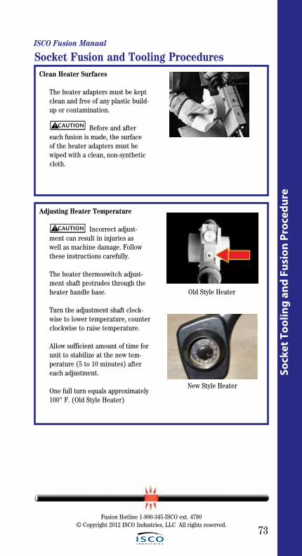
73
Sock
et T
oolin
g an
d Fu
sion
Pro
cedu
re
ISCO Fusion Manual
Fusion Hotline 1-800-345-ISCO ext. 4790© Copyright 2012 ISCO Industries, LLC All rights reserved.
Clean Heater Surfaces
The heater adapters must be kept clean and free of any plastic build- up or contamination.
Before and after each fusion is made, the surface of the heater adapters must be wiped with a clean, non-synthetic cloth.
Adjusting Heater Temperature
Incorrect adjust- ment can result in injuries as well as machine damage. Follow these instructions carefully.
The heater thermoswitch adjust- ment shaft protrudes through the heater handle base.
Turn the adjustment shaft clock- wise to lower temperature, counter clockwise to raise temperature.
Allow sufficient amount of time for unit to stabilize at the new tem- perature (5 to 10 minutes) after each adjustment.
One full turn equals approximately 100° F. (Old Style Heater)
Socket Fusion and Tooling Procedures
CAUTION!
CAUTION!
Old Style Heater
New Style Heater

74
Socket Tooling and Fusion Procedure
ISCO Fusion Manual
Fusion Hotline 1-800-345-ISCO ext. 4790© Copyright 2012 ISCO Industries, LLC All rights reserved.
Cold Weather and Inclement Weather Procedure
• Wind and Precipitation - Heating tool shall be shielded in insulated con-tainer to prevent excessive heat loss. Shield the pipe fusion area and fusion tools from wind, snow, blowing dust and rain by using a canopy or similar device. Protective measures with auxiliary heating is recom-mended when temperatures are below -4°F (-20°C).
• Pipe and Fitting Surface Preparation – The pipe and fitting surfaces to be “joined” or held in clamps shall be dry and clean and free of ice, frost, snow, dirt, and other contamination. After cleaning, the surface shall be protected from contamination until joined. Fittings shall be stored at a warm temperature, such as in a truck cab.
• Heating – Check the temperature of the heating tool regularly with a pyrometer or other surface temperature measuring devise. Do not increase heating tool temperature above the specified temperature (510°F - 266°C) setting. Work quickly once pipe and fittings have been separated from the heating tool; so that melt heat loss is minimized, but still take time (no more than 3 seconds) to inspect both melt patterns. When the ambient temperature becomes colder, it will require a longer heating time to develop an indication of melt and the final bead size. Make sample welds on scrape pipe to develop melt patterns (particu-larly for IPS 2”, 3” and 4in.pipe) using recommended times. When melt pattern is incomplete, increase the soak time 3 seconds in cycles and observe the melt pattern till acceptable.
• Pre-Heating – When the ambient temperature is below 3°F (-16°C), the pipe ends shall be pre-heated using a heating blanket or warm air device to elevate the pipe temperature to improve the heating starting condition.
• Cold Ring Clamps – Pipe outside diameter contracts when colder. This results in loose or slipping cold rings. If set (2) cold ring clamps are available, clamp 1st set in normal position in loose fit.. Place shim material (sand paper/emery cloth) in second set and clamp this set directly behind the first cold ring clamp. The first cold ring clamp allows the pipe adjacent to heated pipe to expand to its normal diam-eter.

Fusion Hotline 1-800-345-ISCO ext. 4790© Copyright 2012 ISCO Industries, LLC All rights reserved.
75
Refe
renc
e
Reference Information: McElroy DataLogger™, Pendant/
Coach™ Equipment &Fusion Pressure Charts
More helpfulInformation!

ISCO Fusion Manual
76
Fusion Hotline 1-800-345-ISCO ext. 4790© Copyright 2012 ISCO Industries, LLC All rights reserved.
Reference
Reference Power Requirements
MachineHeater Power
Facer Power
HydraulicMin. Req.
at sea LevelMiniMc 300 Watt @ 120 VAC, 1Ph Hand Operated None 0.3 KW @ 120 VAC
No. 2LC 800 Watt @ 120 VAC, 1Ph Hand Operated None 0.8 KW @ 120 VAC
No. 2CU 800 Watt @ 120 VAC, 1Ph Hand Operated None 0.8 KW @120 VAC
Socket Fusion
2” - 800 Watt @ 120 VAC, 1Ph4” - 1,200 Watt @ 120 VAC, 1Ph
Not Applicable None
2” - Heater - 0.8 KW @120 VAC
4” - Heater - 2.5 KW @120 VAC
No. 14 1,200 Watt @ 120 VAC, 1Ph
7 Amps @ 120 VAC (Running)
22 Amps @ 120 VAC (Stall)
None2.5 KW
@120 VAC
Side-winder
2” - 800 Watt @ 120 VAC, 1Ph4” - 1,200 Watt @ 120 VAC, 1Ph
Not Applicable None
2” - Heater - 0.8 KW @120 VAC
4” - Heater - 2.5 KW @120 VAC
TracStar No. 28
1,750 Watt @ 120 VAC, 1PhSaddle- 2,270 Watt @ 240 VAC, 1Ph
HydraulicSelf-
ContainedSelf-Contained
Gasoline
No. 28 1,750 Watt @ 120 VAC, 1Ph Hydraulic1 1/2HP, 1Ph @ 120 VAC
3.5 KW @120 VAC
No. 28 CU1,750 Watt @ 120 VAC, 1Ph
Saddle- 2,270 Watt @ 240 VACHydraulic
1 1/2HP, 1Ph @ 120 VAC
4 KW @120 VAC
Mc. 28 Pitbull
1,750 Watt @ 120 VAC, 1Ph Hydraulic1 1/2HP, 1Ph @ 120 VAC
3.5 KW @120 VAC
TracStar No. 412
3,000 Watt @ 240 VAC, 1Ph HydraulicSelf-
ContainedSelf-Contained
Diesel
No. 412 3,000 Watt @ 240 VAC, 1Ph HydraulicSelf-
ContainedSelf-Contained
Gasoline
No. 412E 3,000 Watt @ 240 VAC, 1Ph Hydraulic3 HP, 3Ph
@ 240 VAC5.5 KW / 6.5 KVA @ 240 VAC 60Hz
TracStarNo. 618
3,000 Watt @ 240 VAC, 1Ph HydraulicSelf-
ContainedSelf-Contained
Diesel
No. 618 3,000 Watt @ 240 VAC, 1Ph HydraulicSelf-
ContainedSelf-Contained
Gasoline
No. 618E 3,000 Watt @ 240 VAC, 1Ph Hydraulic5 HP, 3Ph
@ 240 VAC6.5 KW / 7.5 KVA @ 240 VAC 60Hz
TracStar 500
4,000 Watt @ 240 VAC, 1Ph HydraulicSelf-
ContainedSelf-Contained
Diesel
No. 824 10,950 Watt @ 240 VAC, 3Ph Hydraulic7.5 HP, 3Ph @ 240 VAC
17.5 KW / 20 KVA @ 240 VAC 60Hz
TracStar 900
20,461 Watt @ 240 VAC, 3Ph HydraulicSelf-
ContainedSelf-Contained
Diesel
No. 1236 20,461 Watt @ 240 VAC, 3Ph Hydraulic10 HP, 3Ph @ 240 VAC
30 KW / 30 KVA @ 240 VAC 60Hz
No. 1648 35,000 Watt @ 240 VAC, 3Ph Hydraulic10 HP, 3Ph @ 240 VAC
50 KW / 50 KVA @ 240 VAC 60Hz
No. 206565”- 38,437 Watt @ 240 VAC, 3Ph48”- 35,000 Watt @ 240 VAC, 3Ph
Hydraulic10 HP, 3Ph @ 240 VAC
50 KW / 50 KVA @ 240 VAC 60Hz
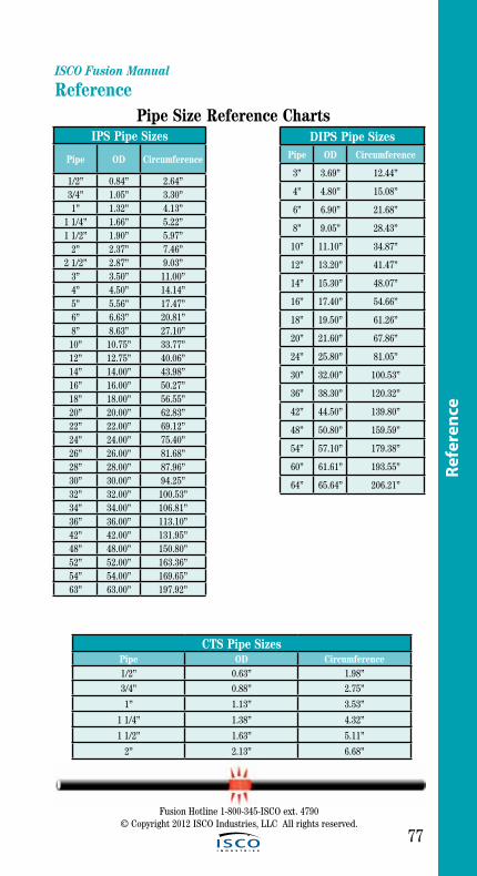
ISCO Fusion Manual
77
Fusion Hotline 1-800-345-ISCO ext. 4790© Copyright 2012 ISCO Industries, LLC All rights reserved.
Refe
renc
e
Reference Pipe Size Reference Charts
IPS Pipe Sizes
Pipe OD Circumference
1/2” 0.84” 2.64”3/4” 1.05” 3.30”1” 1.32” 4.13”
1 1/4” 1.66” 5.22”1 1/2” 1.90” 5.97”
2” 2.37” 7.46”2 1/2” 2.87” 9.03”
3” 3.50” 11.00”4” 4.50” 14.14”5” 5.56” 17.47”6” 6.63” 20.81”8” 8.63” 27.10”
10” 10.75” 33.77”12” 12.75” 40.06”14” 14.00” 43.98”16” 16.00” 50.27”18” 18.00” 56.55”20” 20.00” 62.83”22” 22.00” 69.12”24” 24.00” 75.40”26” 26.00” 81.68”28” 28.00” 87.96”30” 30.00” 94.25”32” 32.00” 100.53”34” 34.00” 106.81”36” 36.00” 113.10”42” 42.00” 131.95”48” 48.00” 150.80”52” 52.00” 163.36”54” 54.00” 169.65”63” 63.00” 197.92”
DIPS Pipe SizesPipe OD Circumference
3” 3.69” 12.44”
4” 4.80” 15.08”
6” 6.90” 21.68”
8” 9.05” 28.43”
10” 11.10” 34.87”
12” 13.20” 41.47”
14” 15.30” 48.07”
16” 17.40” 54.66”
18” 19.50” 61.26”
20” 21.60” 67.86”
24” 25.80” 81.05”
30” 32.00” 100.53”
36” 38.30” 120.32”
42” 44.50” 139.80”
48” 50.80” 159.59”
54” 57.10” 179.38”
60” 61.61” 193.55”
64” 65.64” 206.21”
CTS Pipe SizesPipe OD Circumference1/2” 0.63” 1.98”
3/4” 0.88” 2.75”
1” 1.13” 3.53”
1 1/4” 1.38” 4.32”
1 1/2” 1.63” 5.11”
2” 2.13” 6.68”

ISCO Fusion Manual
78
Fusion Hotline 1-800-345-ISCO ext. 4790© Copyright 2012 ISCO Industries, LLC All rights reserved.
Reference
Reference Pipe Size Reference Charts
Metric ISO Pipe SizesPipe OD Circumference
20 mm 0.79” 2.48”25 mm 0.98” 3.09”32 mm 1.26” 3.96”50 mm 1.97” 6.18”63 mm 2.48” 7.79”75 mm 2.95” 9.28”90 mm 3.54” 11.13”100 mm 3.94” 12.37”110 mm 4.33” 13.61”125 mm 4.92” 15.46”150 mm 5.91” 18.55”160 mm 6.30” 19.79”180 mm 7.09” 22.26”200 mm 7.87” 24.74”225 mm 8.86” 27.83”250 mm 9.84” 30.92”280 mm 11.02” 34.63”315 mm 12.40” 38.96”340 mm 13.39” 42.05”355 mm 13.98” 43.91”400 mm 15.75” 49.47”450 mm 17.72” 55.66”500 mm 19.69” 61.84”560 mm 22.05” 69.26”630 mm 24.80” 77.92”710 mm 27.95” 87.82”800 mm 31.50” 98.95”900 mm 35.43” 111.32”1000 mm 39.37” 123.68”1200 mm 47.24” 148.42”1400 mm 55.12” 173.16”1600 mm 62.99” 197.90”
Metric JIS-1, 1U, 2, 3 Pipe SizesPipe OD Circumference
40 mm 1.89” 5.94”50 mm 2.36” 7.41”75 mm 3.50” 11.00”
100 mm 4.49” 14.10”125 mm 5.51” 17.31”150 mm 6.49” 20.39”175 mm 7.48” 23.50”200 mm 8.50” 26.70”250 mm 10.51” 33.02”300 mm 12.52” 39.33”350 mm 14.57” 45.77”400 mm 16.54” 51.96”
OD Pipe SizesPipe OD Circumference2 5/8” 2.62” 8.25”
4 1/4” 4.25” 13.35”
6.27” 6.27” 19.70”
7 1/8” 7.12” 22.38”
21 1/2” 21.50” 67.54”
What DR (or SDR) Pipe are we
working with?DR (Dimension Ratio) = O.D. ÷ Wall Thickness

ISCO Fusion Manual
79
Fusion Hotline 1-800-345-ISCO ext. 4790© Copyright 2012 ISCO Industries, LLC All rights reserved.
Refe
renc
e
Reference
Hydraulic Fluid Characteristic Chart
The use of proper hydraulic oil is mandatory to achieve maximum performance and machine life. Hydraulic oil should have anti-wear and other special addi-tives. The oil must meet 150 SSU at 100ºF, with the exception of a cold weather operation.
The following table specifies the oil temperature at various viscosities. Temperature rise of the hydraulic oil can vary from 30ºF to about 70ºF over the ambient temperature depending on the pressure setting, age of the pump, wind, etc. Mobile DTE 15M multi-grade hydraulic oil is installed at the factory. The advantage of this oil is a wider temperature range, however, this oil should not be used for continuous operation below 20ºF. For use in extremely cold ambient temperatures, we suggest Mobile DTE 11, which can be used to -16ºF. This oil should not be used for continuous operation above 100ºF (oil temperature).
Note: This chart is based on pump manufacturer recommendations of 100 to 4000 SSU limits.Note: Temperatures shown are fluid temperatures - Not ambient temperatures.

ISCO Fusion Manual
80
Fusion Hotline 1-800-345-ISCO ext. 4790© Copyright 2012 ISCO Industries, LLC All rights reserved.
Reference
Reference Hydraulic Fluid Characteristic Chart
Manufacturer Fluid NameSSU100F
SSU210F
V.I.
Chevron Chevron 32 AW 173 45 100
Chevron 46 AW 238 49 98
Chervon 68 AW 335 54 99
Phillips Magnus A32 170 45 101
Magnus A46 225 48 98
Magnus A68 350 54 98
Shell Tellus T32 150 44 102
Tellus T46 215 48 103
Tellus T68 315 53 89
Sun Sunvis 2105 206 52 167
Sunvis 832 164 44 99
Sunvis 846 236 49 98
Sunvis 868 352 55 98
Unocal Unax AW 32 150 44 107
Unax AW 46 215 48 107
Unax AW 68 315 54 107
Mobil DTE 11M 87 40 145
DTE 13M 165 48 140
DTE 15M 225 53 140
DTE 24 162 44 95
DTE 25 227 47 95
DTE 26 335 53 95
Exxon Univis N-32 177 49 164
Univis N-46 233 55 163
Univis N-68 376 68 160

Hydraulic Fluid Characteristic Chart
-20ºF -10ºF 0ºF 10ºF 30ºF 50ºF 70ºF 90ºF 110ºF 130ºF 150ºFRange
Fahrenheit
15-125
25-142
34-155
15-123
24-136
37-151
-2-124
7-135
20-152
5-140
12-121
23-136
34-152
12-125
20-137
30-152
-27-87
5-130
5-140
23-120
37-137
47-150
5-140
25-142
34-155
ISCO Fusion Manual
81
Fusion Hotline 1-800-345-ISCO ext. 4790© Copyright 2012 ISCO Industries, LLC All rights reserved.
Refe
renc
e
Reference

ISCO Fusion Manual
82
Fusion Equipment Safety Inform
ation
Fusion Hotline 1-800-345-ISCO ext. 4790© Copyright 2012 ISCO Industries, LLC All rights reserved.
Reference
Reference TracStar® Pendant/ Coach Setup
To turn pendant on, turn key to right.To turn pendant off, turn key to off.
Navigate using numeric keys, <+> and <-> keys, <=> key, and <c> key.
Password as shipped from McElroy, 123.
Setup Fusion ParametersWhen starting a job the screen should read time in upper left hand corner. 1 Setup, 2 Pressure, 3 Menu on left side of screen and Face, Soak, Fuse with pressure in center of screen.
Follow instructions on each screen for navigation instructions.Select setup, press 1 on the keyboard.CO92 Parameters Screen Press + use parameters on screen Press - enter new parameters If selected, then screen below will appear.D112 Select Pipe Material List of pipe manufacturers in programmed into Coach, Scroll through list using + or - key, make selection and press = keySO3O Heater Temperature Use Pipe manufacturers recommend temperature, type in temperature and press = Heater off set (-10 for T500, -60, for T900) Enter -, enter password, and enter 10 for T500 or 60 for T900D140 Piston Area Press = to default to 6.010, or enter 4.71 for Pit Bull carriage, 15.32 (Orange Cylinders) or 29.44 (Green Cylinders) for T900SO14 Pipe Size Select IPS, DIPS, OD, mmOD using + or - to scroll up or down Type in pipe size press = SO18 Pipe Wall Thickness Select DR, WT, mmWT using + or - key to scroll Type in parameter selected, press =D122 Heat (IFP) Type in 0, then press =, or enter pipe manufacturers IFP if requiredD124 Soak (IFP) Press - to skipD126 Fuse (IFP) Type in pipe manufacturers recommended IFP usually 75 and press =D128 Cool (IFP) Press - to skipC092 Parameter Screen To allow you to review parameters entered, press + if ok or - to changeS010 Drag (All pendant/coach units use 70 instead of 30) Press + to default to 70 (machine drag) or shift carriage selector valve to close and raise pressure. Using facer pressure valve, raise pressure until carriage starts to move slowly, shift carriage to neutral, let pressure stabilized press + and then = to set drag pressureNOTE: Drag automatically added to Heat and Fuse pressure

ISCO Fusion Manual
83
Fusion Hotline 1-800-345-ISCO ext. 4790© Copyright 2012 ISCO Industries, LLC All rights reserved.
Refe
renc
e
Reference
TracStar® Pendant/Coach DataLogger Operation
DataLogger Operation1ST Screen press 3 for MenuM001 Main Menu Press 2 for Datalogger modeD001 Datalogger Menu Press 1 to Log DataC090 Identifications + To use data recorded on screen or - to enter new dataC100 Machine ID (if - pressed above) Type in machine ID press =C102 Employees No. Type in employee ID press = C104 Job No. Type in Job No. press =C106 Joint No. Type in joint No. press = C090 Indentifications Press + if correct data or - to changeC092 Pipe Parameters + to use data or - to enter new data (Refer to Setup Fusion Parameters if - selected)D134 Drag Pressure Refer to Drag Pressure Setup in Setup Fusion Parameters
Fusion OperationD Screen Press 4 to start Logging - Logging will flash on screen during fusion operationD Screen Press 6 to stop Datalogging - Stop logging before opening carriage or unclamping pipeD150 Datalogging Stopped Press + to view report or - to continueD160 Print Report Press + to print or - to continueD170 Log another joint Press + to Log another joint or - to stop *** If + pressed then refer to C090, C092, and C134 above.

84
ISCO Fusion Manual
Reference
DataLogger™ Operation
Datalogger® DL3Connect Pressure Transducer to Fusion Machine with a proper hydraulic quick disconnect.
Multifunction Switch1. Turns on the Datalogger®® if it is off (both LEDs off). Once turned on, the
Datalogger®® will remain on for 2 minutes is there is no communication activ-ity. Otherwise, the Datalogger®® will stay on as long as there is communication between it and a Recon, Every time this switch is presses, it adds another 2 minutes to the on time.
2. Takes temperature reading if the Datalogger® is on but not in the data log in mode. For as long as this switch is held, the temperature will be displayed on the Recon screen.
3. Stops logging is the Datalogger® is in data logging mode. This switch must be held for longer than 3 seconds to turn off logging.
Note: The Datalogger® turns itself off, therefore, it does not have an OFF switch.
LEDsSolid Orange LED on Datalogger® indicates it is initializing.Flashing Green LED on the Datalogger® indicates it is operating normally.Flashing Red LED on the Datalogger® indicates it is logging data. Holding the Datalogger® button for 3 seconds stops logging.Flashing Blue LED on the Datalogger® indicates Bluetooth® radio in standby mode.Solid Blue LED indicates Datalogger® is communicating with Recon.
ReconTurn on the Recon by pressing the Power button. Turn on the Datalogger® by pushing the multifunction switch.Turn off the Recon by pressing the Power button if it is on. Note: it is best to disconnect (or stop communications) between the Recon and Datalogger® before turning off the Recon. The Datalogger® cannot be turned off, especially while logging data. The Datalogger® will automatically turn itself off if it is not logging data and 2 minutes elapsed since the Recon last communicated with it.Reset: To reset a TDS Recon, hold down the Power button for 5 seconds.
Date and Time: To set date and time: Tap Start> Settings. Tap the System tab. Tap Clock & Alarms. Select the respective time and date field by tapping on it and adjust the values accordingly. For example to change the hour field, tap on it and then use the up and down arrow keys to adjust the number up or down. [For more details, refer to the Setting Time and Date section in the operator’s manual to check and set the correct date and time. It is very important to set the correct time and date because joint reports are time stamped using the Recon’s clock].
Reference
Fusion Hotline 1-800-345-ISCO ext. 4790© Copyright 2012 ISCO Industries, LLC All rights reserved.

85
ISCO Fusion Manual
Reference
Refe
renc
e
DataLogger™ OperationSet up to Log Data
Tap Start > Programs > McElroy DL3-PCC, then Menu > Log/Status. In the Log/Status dialog box, tap Setup…to begin entering information for the next joint. A series of dialog boxes will prompt you to enter the information one step at a time. If SDR or DR is unknown, measure the actual wall thickness and select WT. Enter interfacial pressures and the Recon automatically calculates the corresponding carriage pressures. Drag pressure must be entered for each fusion cycle. See fusion machines operations manual for measuring drag. Enter the measured drag pressure and tab Next. If you tab Next without entering a value, the default drag value of 30 psi will be added by the Datalogger®®. Set the carriage pressures according to the recommended gauge pressures. Measure the heater temperature by holding the top of the Datalogger® about 4 inches from the heater plate and perpendicular to the heater plate, pointing the temperature sensor at the heater plate, Press and hold the Datalogger® multifunction switch to turn on the guidance lasers. Adjust the distance between the Datalogger® and the heater plate until the two laser beams converge to a single point. Use the Recon screen to read the temperature. Once the temperature is stable, release the Dtaalogger multifunction switch to record the temperature. The temperature box flashes *Log xxxoF to indicate the recorded temperature.
Log DataThe pipes should be faced off and aligned. Open the carriage and place the heater on the guide rods between the faced pipe ends. Tab the Start button and wait till the stopwatch appears at the bottom of the Recon screen. Close the carriage to bring the pipe ends against the heater and follow the proper shift sequence on the fusion unit and the pipe manufacturer’s recommendations for fusing pipe. To conserve Recon battery, you may exit the Log/Status dialog box by tapping the X at the top right hang corner and then turn off the Recon. You may turn on the Recon and reconnect to the Datalogger® at any time or near the end of the fusion process. At the end of the fusion process, stop logging before opening the carriage or changing pressures. To stop logging, press and hold the Datalogger® multifunction switch for over 3 seconds or from the Recon. The recording joint report will transfer to the Recon automatically at the end of each joint when the Recon is connected to the Datalogger®. The latest report appears on the screen for review.
Recommended PrecautionsFully charge the Recon before each use for optimal battery performance. Stop communications and then turn off the Recon whenever monitoring is not necessary. Make copies of the reports on a PC or print our hard copied to prevent data loss. For more complete details of the Datalogger® see the operator’s manual.
Fusion Hotline 1-800-345-ISCO ext. 4790© Copyright 2012 ISCO Industries, LLC All rights reserved.
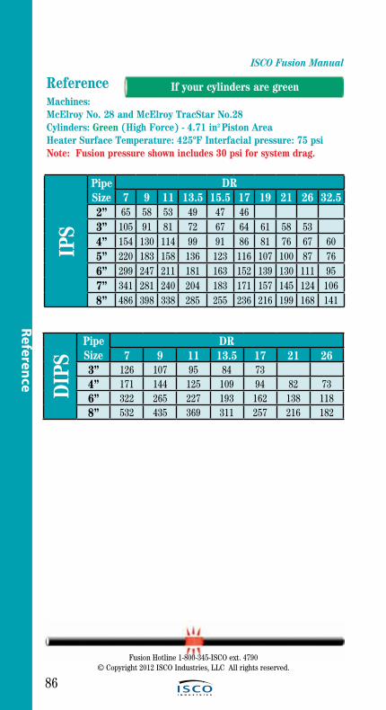
ISCO Fusion Manual
86
Reference
Reference
PipeSize
DR7 9 11 13.5 15.5 17 19 21 26 32.5
2” 65 58 53 49 47 463” 105 91 81 72 67 64 61 58 534” 154 130 114 99 91 86 81 76 67 605” 220 183 158 136 123 116 107 100 87 766” 299 247 211 181 163 152 139 130 111 957” 341 281 240 204 183 171 157 145 124 1068” 486 398 338 285 255 236 216 199 168 141
IPS
Machines: McElroy No. 28 and McElroy TracStar No.28Cylinders: Green (High Force) - 4.71 in2 Piston AreaHeater Surface Temperature: 425ºF Interfacial pressure: 75 psiNote: Fusion pressure shown includes 30 psi for system drag.
PipeSize
DR7 9 11 13.5 17 21 26
3” 126 107 95 84 734” 171 144 125 109 94 82 736” 322 265 227 193 162 138 1188” 532 435 369 311 257 216 182
DIP
S
Fusion Hotline 1-800-345-ISCO ext. 4790© Copyright 2012 ISCO Industries, LLC All rights reserved.
If your cylinders are green
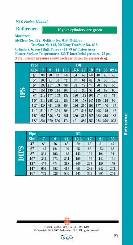
ISCO Fusion Manual
87
ReferenceMachines: McElroy No. 412, McElroy No. 618, McElroy TracStar No.412, McElroy TracStar No. 618Cylinders: Green (High Force) - 11.78 in2 Piston AreaHeater Surface Temperature: 425ºF Interfacial pressure: 75 psiNote: Fusion pressure shown includes 30 psi for system drag.
PipeSize
DR7 9 11 13.5 15.5 17 19 21 26 32.5
4” 80 70 63 58 54 52 50 48 45 425” 106 91 81 72 67 64 61 58 53 486” 137 117 103 90 83 79 74 70 62 567” 154 130 114 100 91 86 81 76 68 608” 212 177 153 132 120 112 104 97 85 7410” 313 258 221 189 170 158 145 135 115 9912” 428 351 299 253 226 210 192 177 150 12714” 510 417 354 299 267 247 225 208 175 14716” 657 536 453 381 339 313 285 262 219 18318” 824 670 566 474 421 389 353 324 270 223
IPS
PipeSize
DR7 9 11 13.5 17 21 26
4” 86 76 68 62 56 51 476” 147 124 109 95 83 73 658” 231 192 165 142 121 104 9110” 332 273 234 199 166 142 12112” 457 374 318 269 223 188 15914” 603 492 417 351 289 242 20316” 772 628 530 445 365 305 254
DIP
S
Fusion Hotline 1-800-345-ISCO ext. 4790© Copyright 2012 ISCO Industries, LLC All rights reserved.
If your cylinders are green
Refe
renc
e

ISCO Fusion Manual
88
Reference
Reference
Machines: McElroy No. 412, McElroy No. 618, McElroy TracStar No. 412, McElroy TracStar No. 618, McElroy TracStar No. 500 Series II (Manifold Equipped)Cylinders: Orange (Medium Force) - 6.01 in2 Piston AreaHeater Surface Temperature: 425ºF Interfacial pressure: 75 psiNote: Fusion pressure shown includes 30 psi for system drag.
PipeSize
DR7 9 11 13.5 15.5 17 19 21 26 32.5
4” 127 108 96 84 78 74 70 66 59 545” 179 150 130 113 103 97 90 85 75 666” 241 200 172 148 134 125 116 108 94 817” 274 227 194 167 150 140 129 120 104 898” 387 318 271 230 206 191 175 162 138 11710” 585 477 404 341 303 281 256 235 198 16512” 810 659 557 467 415 383 348 319 266 22014” 971 789 665 557 494 455 413 378 314 25916” 1,259 1,021 859 718 636 586 530 485 401 32918” 1,585 1,285 1,080 901 797 733 663 606 500 40920” 1,950 1,579 1,326 1,106 976 898 812 741 610 498
IPS
PipeSize
DR7 9 11 13.5 17 21 26
4” 141 119 105 92 80 71 636” 259 214 184 158 133 115 998” 423 347 295 250 208 176 14910” 621 507 429 361 297 249 20912” 866 705 595 499 408 340 28314” 1,154 936 788 659 538 446 36916” 1,483 1,202 1,011 844 687 568 46918” 1,855 1,502 1,262 1,052 855 706 581
DIP
S
T-500
Fusion Hotline 1-800-345-ISCO ext. 4790© Copyright 2012 ISCO Industries, LLC All rights reserved.
T-500
If your cylinders are orange

PipeSize
DR7 9 11 13.5 15.5 17 19 21 26 32.5
8” 103 89 79 71 66 63 60 57 52 4810” 143 121 106 93 86 81 76 72 64 5812” 189 158 138 119 109 102 95 89 78 6914” 222 185 160 138 125 117 108 101 88 7716” 281 232 199 171 154 143 132 123 106 9118” 348 286 244 208 187 174 159 148 126 10720” 422 346 295 250 223 207 190 175 148 125
21.5” 483 395 336 284 253 235 214 198 167 14022” 504 413 350 296 264 244 223 206 173 14624” 594 485 411 346 308 285 260 239 200 16726” 564 477 401 357 330 300 275 230 19128” 650 549 460 409 377 343 315 262 21730” 741 625 524 465 429 389 357 296 24532” 839 707 592 525 484 439 402 333 27434” 795 665 588 542 491 450 372 30636” 887 741 656 604 547 500 414 339
ISCO Fusion Manual
89
ReferenceIP
S
Machines: McElroy No. 824, McElroy No. 1236, McElroy TracStar No. 900 (Manifold Equipped) Cylinders: Green (High Force) - 29.44 in2 Piston AreaHeater Surface Temperature: 425ºF Interfacial pressure: 75 psiNote: Fusion pressure shown includes 30 psi for system drag.
PipeSize
DR7 9 11 13.5 17 21 26
8” 110 95 84 75 66 60 5410” 151 127 111 98 85 75 6612” 201 168 145 126 107 93 8214” 259 215 185 158 134 115 9916” 327 269 230 196 164 140 12018” 403 331 282 239 198 168 14320” 487 399 339 286 237 199 16824” 556 470 395 325 272 22730” 707 592 484 402 333
DIP
S
Fusion Hotline 1-800-345-ISCO ext. 4790© Copyright 2012 ISCO Industries, LLC All rights reserved.
If your cylinders are green
Refe
renc
e

ISCO Fusion Manual
90
Reference
Reference
Machines: McElroy No. 824, McElroy No. 1236, McElroy TracStar No. 900 (Manifold Equipped)Cylinders: Orange (Medium Force) - 15.32 in2 Piston AreaHeater Surface Temperature: 425ºF Interfacial pressure: 75 psiNote: Fusion pressure shown includes 30 psi for system drag.
PipeSize
DR7 9 11 13.5 15.5 17 19 21 26 32.5
8” 170 143 125 108 99 93 87 82 72 6410” 248 206 177 152 137 128 119 111 96 8312” 336 277 237 201 181 168 155 143 122 10514” 399 328 279 237 212 197 180 167 141 12016” 512 419 355 300 268 248 226 209 176 14718” 640 522 442 372 331 306 278 256 214 17920” 783 638 538 452 401 371 337 309 258 213
21.5” 901 732 618 518 459 424 384 352 293 24222” 941 765 645 541 479 442 401 368 305 25224” 1,115 905 762 638 565 520 472 432 358 29426” 1,057 889 743 657 606 548 502 414 34028” 1,221 1,027 857 758 698 631 577 476 39030” 1,397 1,174 979 865 796 720 658 542 44332” 1,585 1,332 1,110 981 902 815 744 612 50034” 1,499 1,249 1,103 1,014 916 836 688 56036” 1,677 1,397 1,233 1,134 1,024 934 767 624
IPS
PipeSize
DR7 9 11 13.5 17 21 26
8” 184 154 134 116 100 87 7710” 262 217 187 160 135 116 10012” 358 295 251 214 178 152 12914” 471 386 328 277 229 193 16316” 600 490 415 349 288 241 20218” 746 608 513 431 354 295 24620” 909 739 623 522 427 355 29524” 1,041 876 732 597 494 40930” 1,332 1,110 902 744 612
DIP
S
Fusion Hotline 1-800-345-ISCO ext. 4790© Copyright 2012 ISCO Industries, LLC All rights reserved.
If your cylinders are orange
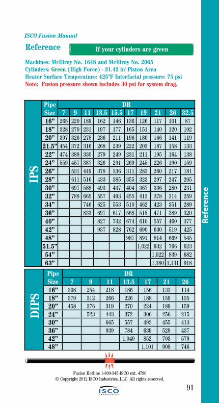
ISCO Fusion Manual
91
Reference
PipeSize
DR7 9 11 13.5 15.5 17 19 21 26 32.5
16” 265 220 189 162 146 136 126 117 101 8718” 328 270 231 197 177 165 151 140 120 10220” 397 326 278 236 211 196 180 166 141 119
21.5” 454 372 316 268 239 222 203 187 158 13322” 474 388 330 279 249 231 211 195 164 13824” 559 457 387 326 291 269 245 226 190 15926” 531 449 378 336 311 283 260 217 18128” 611 516 433 385 355 323 297 247 20530” 697 588 493 437 404 367 336 280 23132” 788 665 557 493 455 413 378 314 25934” 746 625 553 510 462 423 351 28936” 833 697 617 568 515 471 389 32040” 827 732 674 610 557 460 37742” 937 828 762 690 630 519 42548” 987 891 814 669 545
51.5” 1,022 932 766 62354” 1,022 839 68263” 1,380 1,131 918
IPS
Machines: McElroy No. 1648 and McElroy No. 2065 Cylinders: Green (High Force) - 31.42 in2 Piston AreaHeater Surface Temperature: 425ºF Interfacial pressure: 75 psiNote: Fusion pressure shown includes 30 psi for system drag.
PipeSize
DR7 9 11 13.5 17 21 26
16” 308 254 218 186 156 133 11418” 379 312 266 226 188 159 13520” 458 376 319 270 224 189 15924” 523 443 372 306 256 21530” 665 557 493 455 41336” 939 784 639 529 43742” 1,049 852 703 57948” 1,101 908 746
DIP
SIf your cylinders are green
Refe
renc
e
Fusion Hotline 1-800-345-ISCO ext. 4790© Copyright 2012 ISCO Industries, LLC All rights reserved.
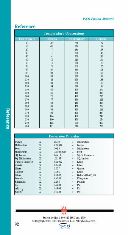
ISCO Fusion Manual
92
Fusion Hotline 1-800-345-ISCO ext. 4790© Copyright 2012 ISCO Industries, LLC All rights reserved.
Reference Temperature Conversions
Fahrenheit Celsius Fahrenheit Celsius0
102030405060708090
100110120130140150160170180190200210220230240250
-18-12-7-14
1016212732384349546065717782889399
104110115121
260270280290300310320330340350360370380390400410420430440450460470480490500510
127132138143149154160165171176182188193199204210215221226232238243249254260265
Conversion Formulas
Inches X 25.40 = MillimetersMillimeters X 0.03937 = InchesFeet X 304.8 = MillimetersMillimeters X .003280839 = FeetSQ. Inches X 645.16 = SQ. MillimetersSQ. Millimeters X .00155 = SQ. InchesOunces(fluid) US X 0.02957 = LitersQuarts X 0.9463 = LitersLiters X 1.057 = QuartsGallons X 3.785 = LitersLiters X 0.2642 = Gallons(fluid) USPounds X 0.4536 = KilogramsKilograms X 2.205 = PoundsBar X 14.503 = PsimPa X 145.03 = PsiKg/cm
2 X 14.223 = Psi
Reference

ISCO Fusion Manual
93
Fusion Hotline 1-800-345-ISCO ext. 4790© Copyright 2012 ISCO Industries, LLC All rights reserved.
Refe
renc
e
Reference References
1. Plastics Pipe Institute Technical Report-33. Generic Butt Fusion Joining Procedure for Polyethylene Gas Pipe, 2001
2. Plastics Pipe Institute Technical Report-41. Generic Saddle Fusion Joining Procedure for Polyethylene Gas Pipe, 2002
3. Plastics Pipe Institute. Polyethylene Joining Procedures, March 1998.
4. ASTM D2657-97. Standard Practice for Heat Fusion Joining of Polyolefin Pipe and Fittings. Volume 8.04. American Society of Testing and Materials. Baltimore, 2002.
5. ASTM F1056-97. Standard Specification for Socket Fusion Tools for Use in Socket Fusion Joining Polyethylene Pipe or Tubing and Fittings. Volume 8.04. American Society of Testing and Materials. Baltimore, 2002.
6. Pipeline Safety Regulations. U.S. Department of Transportation. CFR 49. Washington, 2002.

ISCO Fusion Manual
94
Fusion Hotline 1-800-345-ISCO ext. 4790© Copyright 2012 ISCO Industries, LLC All rights reserved.
Notes

NotesISCO Fusion Manual
95
Fusion Hotline 1-800-345-ISCO ext. 4790© Copyright 2012 ISCO Industries, LLC All rights reserved.

96Fusion Hotline 1-800-345-ISCO ext. 4790
© Copyright 2012 ISCO Industries, LLC All rights reserved.
AcknowledgementsMcElroy Manufacturing, Inc.
Plastic Pipe Institute
Brand Names and product names are trademarks of their respective owners.