English Fitting Instructions: Trophy and Trophy SE … Fitting Instructions: Trophy and Trophy SE...
11
1 of 11 Publication part number A9900644 issue 1, ADC 11591 © Triumph Designs Ltd. 2012 English Fitting Instructions: Trophy and Trophy SE A9508161 and A9508156 Thank you for choosing this Triumph genuine accessory kit. This accessory kit is the product of Triumph's use of proven engineering, exhaustive testing, and continuous striving for superior reliability, safety and performance. Completely read all of these instructions before commencing the installation of the accessory kit in order to become thoroughly familiar with the kit’s features and the installation process. These instructions should be considered a permanent part of your accessory kit, and should remain with it even if your accessory-equipped motorcycle is subsequently sold. A9508161 Parts Supplied: 1. Sliding carriage assembly 1 off 8. Flanged sleeve - short 2 off 2. Sub-harness (top box) 1 off 9. Flanged sleeve - long 2 off 3. Self-tapping screw 3 off 10. Bolt, M8 x 43 mm 2 off 4. Harness retainer 1 off 11. Bolt, M8 x 65 mm 2 off 5. Harness cover 1 off 12. Fir-tree clip 1 off 6. Relay 1 off 13. Cable tie 1 off 7. Clamp plate 1 off
Transcript of English Fitting Instructions: Trophy and Trophy SE … Fitting Instructions: Trophy and Trophy SE...

1 of 11Publication part number A9900644 issue 1, ADC 11591© Triumph Designs Ltd. 2012
English
Fitting Instructions:Trophy and Trophy SEA9508161 and A9508156Thank you for choosing this Triumph genuine accessory kit. This accessory kit is the product of Triumph's use of provenengineering, exhaustive testing, and continuous striving for superior reliability, safety and performance.
Completely read all of these instructions before commencing the installation of the accessory kit in order to becomethoroughly familiar with the kit’s features and the installation process.
These instructions should be considered a permanent part of your accessory kit, and should remain with it even if youraccessory-equipped motorcycle is subsequently sold.
A9508161
Parts Supplied:
1. Sliding carriage assembly 1 off 8. Flanged sleeve - short 2 off
2. Sub-harness (top box) 1 off 9. Flanged sleeve - long 2 off
3. Self-tapping screw 3 off 10. Bolt, M8 x 43 mm 2 off
4. Harness retainer 1 off 11. Bolt, M8 x 65 mm 2 off
5. Harness cover 1 off 12. Fir-tree clip 1 off
6. Relay 1 off 13. Cable tie 1 off
7. Clamp plate 1 off
2 of 11
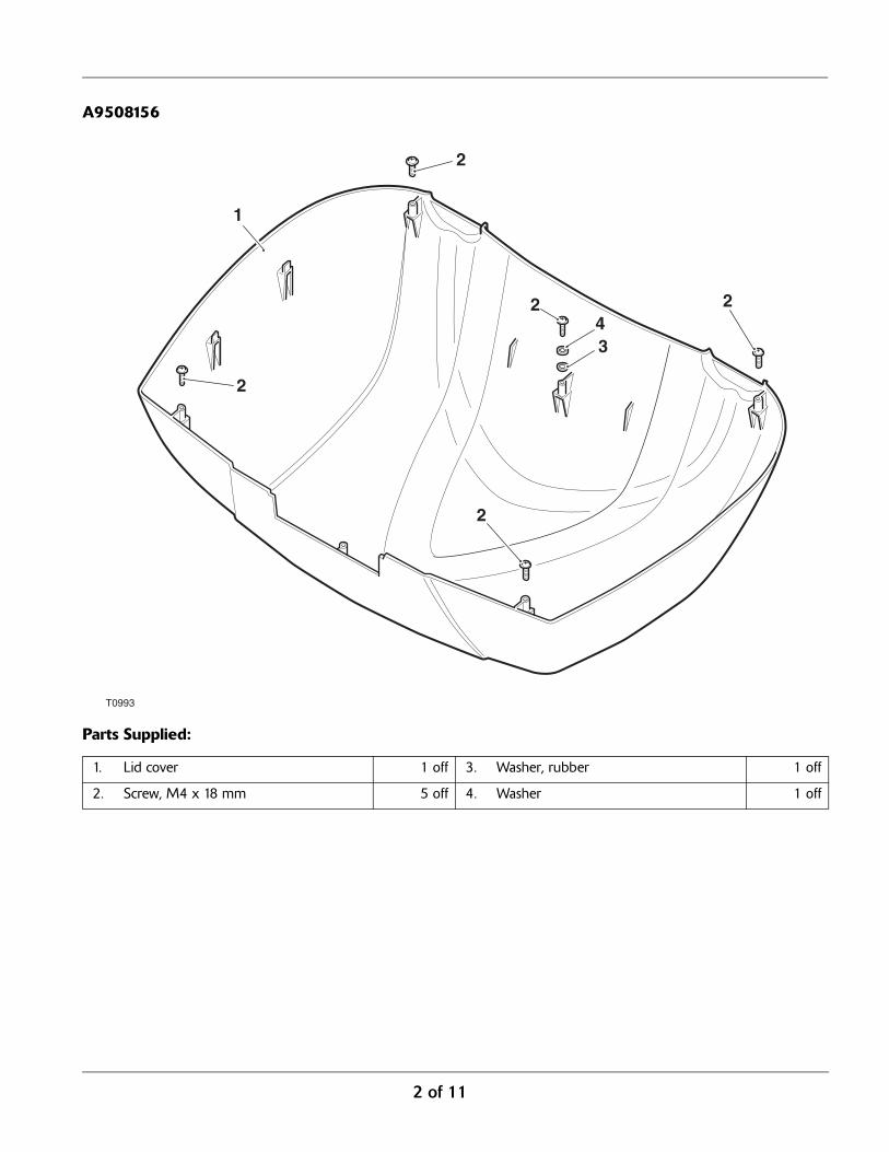
A9508156
Parts Supplied:
1. Lid cover 1 off 3. Washer, rubber 1 off
2. Screw, M4 x 18 mm 5 off 4. Washer 1 off
T0993
1
2
2
34
2
2
2

3 of 11
1. Disconnect the battery, as described in the servicemanual.
2. Remove the luggage rack cover, as described in theservice manual.
3. Remove the luggage rack, as described in the servicemanual.
4. Remove the left hand rear panel, as described in theservice manual.
5. Remove the right hand side panel, as described in theservice manual.
6. Turn the luggage rack over and place on a suitablenon-abrasive surface.
7. Locate the clamp plate in position on the underside ofthe luggage rack, as shown and retain with the fir-treeclip provided.
1. Luggage rack2. Clamp plate3. Fir-tree clip
8. Locate the top box power connector which is situatedat the rear, left hand side, of the motorcycle under theleft hand rear panel.
9. Remove the blanking plug from the top box powerconnector. Retain the blanking plug if the motorcycle isreturned to its original condition
1. Top box power connector2. Blanking plug
WarningThis accessory kit is designed for use on Triumph Trophyand Trophy SE motorcycles only and should not be fittedto any other Triumph model or any other manufacturer’smotorcycle. Fitting this accessory kit to any other Triumphmodel or any other manufacturer’s motorcycle, will affectthe performance, stability and handling of the motorcycle.This may affect the rider’s ability to control the motorcycleand could cause an accident.
WarningAlways have Triumph approved parts, accessories andconversions fitted by a trained technician of an authorisedTriumph dealer. The fitment of parts, accessories andconversions by a technician who is not of an authorisedTriumph dealer may affect the handling, stability or otheraspects of the motorcycle’s operation which may result inloss of motorcycle control and an accident.
WarningThroughout this operation, ensure that the motorcycle isstabilised and adequately supported to prevent risk ofinjury from the motorcycle falling.
WarningA torque wrench of known accurate calibration must beused when fitting this accessory kit. Failure to tighten anyof the fasteners to the correct torque specification mayresult in loss of motorcycle control and an accident.

4 of 11
10. Remove the blanking plug from the sliding carriageassembly to expose the top box connector block.Retain the blanking plug for reuse when a top box isnot fitted for extended periods.
1. Sliding carriage assembly2. Top box connector block3. Blanking plug
11. Feed the sub-harness, female connector end, throughthe subframe towards the top box power connector.
1. Sub-harness, female connector2. Top box power connector3. Motorcycle subframe
12. Connect the sub-harness to the top box powerconnector.
1. Sub-harness2. Top box power connector
Note:
• Before the sub-harness can be routed throughthe luggage rack, the terminals must carefully bepushed out of the sub-harness terminal block.This will allow the terminal block to be rotatedand pass through the access hole in the luggagerack.
13. Pass the sub-harness through the access hole, from theunderside of the luggage rack.
1. Luggage rack2. Sub-harness3. Sub-harness terminal block
5 of 11
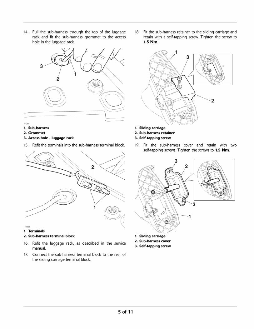
14. Pull the sub-harness through the top of the luggagerack and fit the sub-harness grommet to the accesshole in the luggage rack.
1. Sub-harness2. Grommet3. Access hole - luggage rack
15. Refit the terminals into the sub-harness terminal block.
1. Terminals2. Sub-harness terminal block
16. Refit the luggage rack, as described in the servicemanual.
17. Connect the sub-harness terminal block to the rear ofthe sliding carriage terminal block.
18. Fit the sub-harness retainer to the sliding carriage andretain with a self-tapping screw. Tighten the screw to1.5 Nm.
1. Sliding carriage2. Sub-harness retainer3. Self-tapping screw
19. Fit the sub-harness cover and retain with twoself-tapping screws. Tighten the screws to 1.5 Nm.
1. Sliding carriage2. Sub-harness cover3. Self-tapping screw

6 of 11
20. Secure the sub-harness to the sub-harness cover with acable tie, as shown below. Trim off any excess cable tiematerial.
1. Sub-harness cover2. Sub-harness3. Cable tie
21. Fit the flanged sleeves into the luggage rack, with thelonger sleeves positioned to the front.
1. Luggage rack2. Flanged sleeve - long3. Flanged sleeve - short
22. Fit the two M8 x 65 mm bolts to the front slidingcarriage fixing positions and the two M8 x 43 mmbolts to the rear sliding carriage fixing positions.
1. Sliding carriage2. M8 x 65 mm bolt (front fixings)3. M8 x 43 mm bolt (rear fixings)
23. Locate the sliding carriage assembly on to the luggagerack, aligning the four fixings with the flanged sleevesin the luggage rack.
24. Tighten the four fixings to 27 Nm.
WarningThe sliding carriage must be allowed to move from side toside on the slide plate. If the sliding carriage is not free tomove from side to side when the top box is fitted, thestability and handling characteristics of the motorcyclemay be affected, leading to loss of control and an accident.
WarningThe top box sliding carriage is intended for fitment of theTriumph Genuine Accessory top box only. If a load isadded to the top box sliding carriage, the load must:
• be applied and secured as stated previously forluggage rack loading in the owner’s handbook;
• not exceed the 10 kg total payload as statedpreviously;
• not restrict the sliding carriage mechanism.
Do not restrict the sliding carriage mechanism asmotorcycle stability will be affected. Riding the motorcyclewith the sliding mechanism restricted may cause themotorcycle to become unstable leading to loss ofmotorcycle control and an accident.

7 of 11
25. Fit the relay provided into the spare socket at the mainharness relay block.
1. Relay
26. Refit the left hand rear panel, as described in theservice manual.
27. Refit the right hand side panel, as described in theservice manual.
28. Reconnect the battery, as described in the servicemanual.
29. Fit a top box on to the sliding carriage, ensuring theelectrical connection is made.
30. Connect a suitable 12 volt component to the auxiliarypower socket in the top box to confirm an electricalfeed is present.
Top Box - Lid Cover A9508156
1. Lay the top box on a flat, clean and soft surface.
2. Retrieve the painted panel from the kit. Fit the panel tothe lid ensuring that it fits inside the latch platesurround.
1. Painted panel2. Latch plate surround
3. Retrieve the five self-tapping screws, one metal washerand one rubber washer from the kit. Fit the metalwasher to one of the screws then fit the rubber washerto the same screw.
4. Carefully open the top box lid, ensuring that thepainted cover remains tight to the lid and will rest onthe clean soft surface when fully open.
CautionCare must be taken when working on the top box.Damage to the top box surfaces may result frominadequate care while fitting the painted panel.
T0986
1
2

8 of 11
5. Fit the self-tapping screws to the locations indicatedbelow and tighten to 1.5 Nm.
1. Screw with washers2. Screws without washers
Fitting the Lock Barrel to Top Box
1. Fit the ignition key into the lock barrel lock suppliedwith the motorcycle when new.
Note:
• The lock barrel will only fit one way.2. Align the locking device on the lock barrel to the slot in
the lock housing in the top box, as indicated in theillustration below.
1. Slot2. Housing3. Locking device
3. Push the barrel into position in the top box until itclicks into place.
4. Check the operation of the barrel.
T0987
1
22
22
21
3
9 of 11
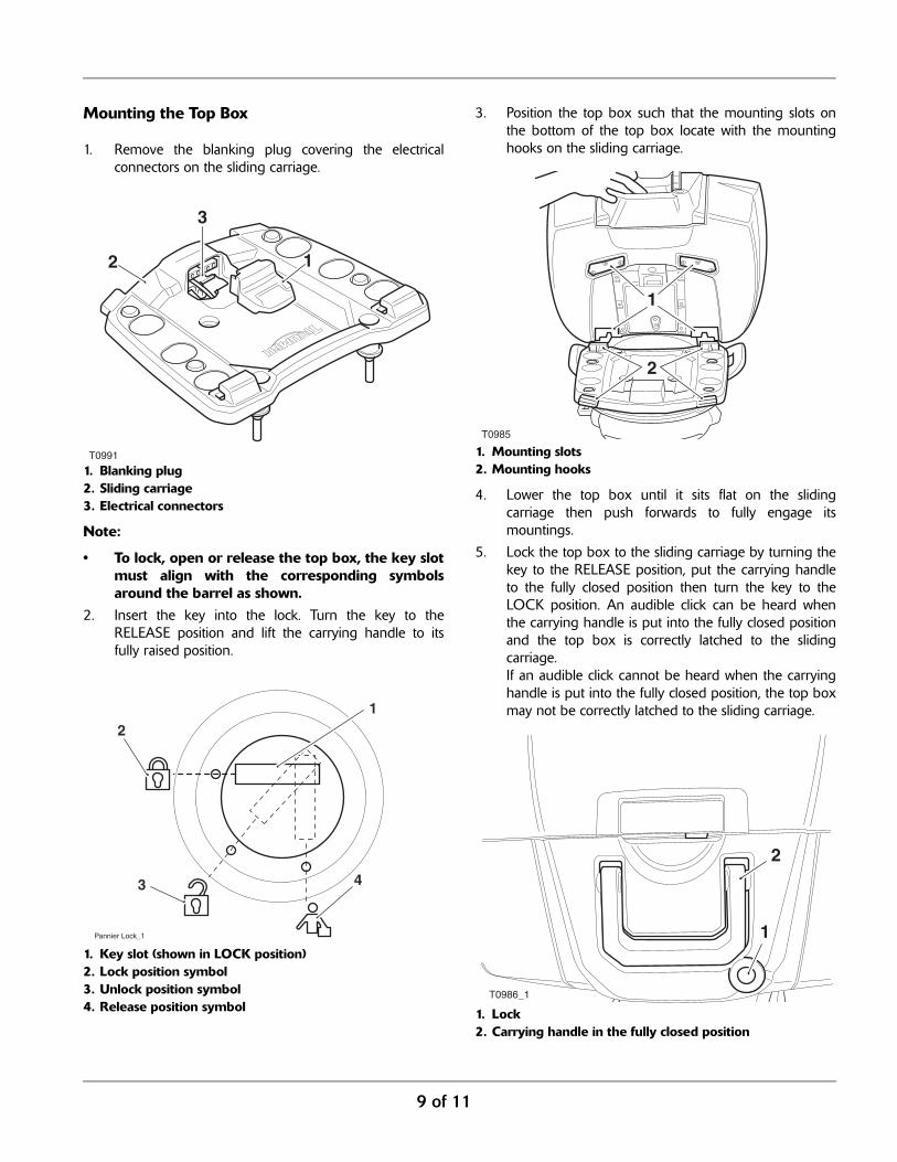
Mounting the Top Box
1. Remove the blanking plug covering the electricalconnectors on the sliding carriage.
1. Blanking plug2. Sliding carriage3. Electrical connectors
Note:
• To lock, open or release the top box, the key slotmust align with the corresponding symbolsaround the barrel as shown.
2. Insert the key into the lock. Turn the key to theRELEASE position and lift the carrying handle to itsfully raised position.
1. Key slot (shown in LOCK position)2. Lock position symbol3. Unlock position symbol4. Release position symbol
3. Position the top box such that the mounting slots onthe bottom of the top box locate with the mountinghooks on the sliding carriage.
1. Mounting slots2. Mounting hooks
4. Lower the top box until it sits flat on the slidingcarriage then push forwards to fully engage itsmountings.
5. Lock the top box to the sliding carriage by turning thekey to the RELEASE position, put the carrying handleto the fully closed position then turn the key to theLOCK position. An audible click can be heard whenthe carrying handle is put into the fully closed positionand the top box is correctly latched to the slidingcarriage.If an audible click cannot be heard when the carryinghandle is put into the fully closed position, the top boxmay not be correctly latched to the sliding carriage.
1. Lock2. Carrying handle in the fully closed position
T0991
12
3
2
3 4
1
Pannier Lock_1
T0985
1
2
T0986_1
1
2
10 of 11
Note:
• It is recommended to have the top box in thelocked condition while riding the motorcycle.
6. Check that the top box is securely locked to the slidingcarriage.
Removing the Top Box
1. Insert the key and turn it to the RELEASE position.
2. Lift the carrying handle to the fully raised position, pullthe top box rearwards and remove it from the slidingcarriage.
Top Box Operation
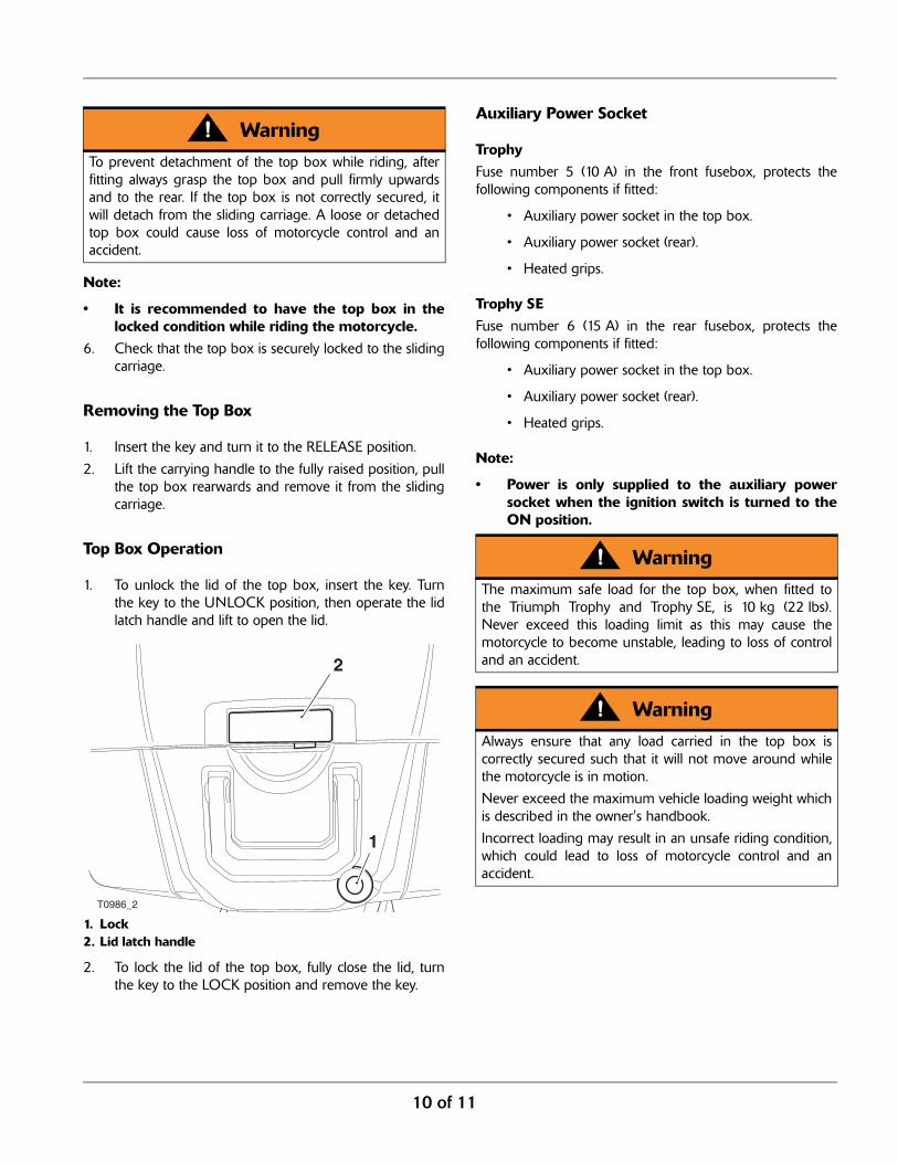
1. To unlock the lid of the top box, insert the key. Turnthe key to the UNLOCK position, then operate the lidlatch handle and lift to open the lid.
1. Lock2. Lid latch handle
2. To lock the lid of the top box, fully close the lid, turnthe key to the LOCK position and remove the key.
Auxiliary Power Socket
TrophyFuse number 5 (10 A) in the front fusebox, protects thefollowing components if fitted:
• Auxiliary power socket in the top box.
• Auxiliary power socket (rear).
• Heated grips.
Trophy SEFuse number 6 (15 A) in the rear fusebox, protects thefollowing components if fitted:
• Auxiliary power socket in the top box.
• Auxiliary power socket (rear).
• Heated grips.
Note:
• Power is only supplied to the auxiliary powersocket when the ignition switch is turned to theON position.
WarningTo prevent detachment of the top box while riding, afterfitting always grasp the top box and pull firmly upwardsand to the rear. If the top box is not correctly secured, itwill detach from the sliding carriage. A loose or detachedtop box could cause loss of motorcycle control and anaccident.
T0986_2
1
2
WarningThe maximum safe load for the top box, when fitted tothe Triumph Trophy and Trophy SE, is 10 kg (22 lbs).Never exceed this loading limit as this may cause themotorcycle to become unstable, leading to loss of controland an accident.
WarningAlways ensure that any load carried in the top box iscorrectly secured such that it will not move around whilethe motorcycle is in motion.
Never exceed the maximum vehicle loading weight whichis described in the owner's handbook.
Incorrect loading may result in an unsafe riding condition,which could lead to loss of motorcycle control and anaccident.

11 of 11
WarningTo maintain the handling characteristics of the motorcyclewhen riding with luggage or with a passenger andluggage, refer to the owner's handbook for the correctsuspension settings.
Incorrect suspension settings could significantly changethe handling characteristics of the motorcycle, leading toloss of motorcycle control and an accident.
WarningAfter fitting the accessory kit the motorcycle will exhibitnew handling characteristics. Operate the motorcycle in asafe area free from traffic to gain familiarity with any newcharacteristics. Operation of the motorcycle when notfamiliar with any new handling characteristics may result inloss of motorcycle control and an accident.
WarningIf, after fitment of this accessory kit, you have any doubtabout the performance of any aspect of the motorcycle,contact an authorised Triumph dealer and do not ride themotorcycle until the authorised dealer has declared it fitfor use. Riding a motorcycle when there is any doubt as toany aspect of the performance of the motorcycle mayresult in loss of control of the motorcycle leading to anaccident.
WarningNever ride an accessory equipped motorcycle at speedsabove 80 mph (130 km/h). The presence of accessorieswill cause changes in the stability and handling of themotorcycle. Failure to allow for changes in motorcyclestability may lead to loss of control or an accident.Remember that the 80 mph (130 km/h) limit will bereduced by the fitting of non-approved accessories,incorrect loading, worn tyres, overall motorcycle conditionand poor road or weather conditions.
WarningThe motorcycle must not be operated above the legalroad speed limit except in closed course conditions.
WarningOnly operate this Triumph motorcycle at high speed inclosed course, on-road competitions or on closed courserace tracks. High speed operation should only beattempted by riders who have been instructed in thetechniques necessary for high speed riding and arefamiliar with the motorcycle’s characteristics in allconditions. High speed operation in any othercircumstances is dangerous and will lead to loss ofmotorcycle control and an accident.