Engine/Gearbox Combinations - Skoda Fabia Club
15
12 Engine/Gearbox Combinations Engine code letters ARV/ATY AME ATZ Displacement 1.0 ltr. 1.4 ltr. 1.4 ltr. Power output 37 kW/50 HP 50 kW/68 HP 50 kW/68 HP Engine management system Simos 3PB Simos 3PB Simos 3PA Emission standard ARV/EU2 ATY/D4; EU4 EU2 D4 EU4 Transmission 002 (with technical improvements) Note: The table presents the engine versions at the start of production. Other engines are envisaged, e.g. 2.0-ltr./88 kW engine. The emission standard EU4 comes into effect from the year 2005! SP32_08 SP32_07 SP32_08 SP32_05
Transcript of Engine/Gearbox Combinations - Skoda Fabia Club

12
Engine/Gearbox Combinations
Engine code letters ARV/ATY AME ATZ
Displacement 1.0 ltr. 1.4 ltr. 1.4 ltr.
Power output 37 kW/50 HP 50 kW/68 HP 50 kW/68 HP
Engine management system
Simos 3PB Simos 3PB Simos 3PA
Emission standard ARV/EU2ATY/D4; EU4
EU2 D4EU4
Transmission 002 (with technical improvements)
Note:
The table presents the engine
versions at the start of
production.
Other engines are envisaged,
e.g. 2.0-ltr./88 kW engine.
The emission standard EU4
comes into effect from the
year 2005!
SP32_08SP32_07 SP32_08
SP32_05

13
AUA AUB ASY ATD
1.4 ltr. 1.4 ltr. 1.9 ltr. 1.9 ltr.
55 kW/75 HP 74 kW/100 HP 47 kW/64 HP 74 kW/100 HP
Magneti Marelli4LV
Magneti Marelli4LV
SDI TDI
EU4 EU4 EU3 EU3
SP32_22SP32_22 SP32_24
SP32_06
SP32_99
Gearbox 02T (a new development for engine
torques up to 200 Nm)
Gearbox 02R (the familiar gearbox 02J, matched to the FABIA for engine torques up to 250 Nm)
SP32_102

14
Engines
The mechanical components
– Crankshaft mounted in 3 bearings
– The camshaft in the block is driven by a duplex roller chain
– Valve gear employing tappets, tappet rods and rocker arms, hydraulic valve clearance compensation
– “Wet” grey cast iron cylinder liners
– Aluminium die cast cylinder block
You can find further information in SSP 35.
1.0-ltr. engine (37 kW) ARV/ATY
SP32_07
SP32_17
The engine management system
– Simos 3PB multipoint fuel injection
– Rotorless high-voltage distribution
– Sequential fuel injection
– Sender for engine speed and TDC recognition and camshaft position sensor
Technical data
Type: 4-cyl. inline engineValves per cylinder: 2Displacement:
997 cm
3
Bore: 72 mmStroke: 61.2 mmCompression ratio: 10 : 1Rated output: 37 kW at 5000 rpmMax. torque: 84 Nm at 3250 rpmEmission control: Catalytic converter,
lambda controlEmission standard: ARV/EU2
ATY/D4; EU4Fuel: Unleaded petrol 95
RON (91 possible, with reduced output)
n (1/min)1000 50002000 3000 4000 6000

15
The mechanical components
The mechanical design of the engine is identical to that of the 1.4-ltr./44 kW engine.
You can find further information in SSP 27.
Modifications relate to the software in the engine management system.
1.4-ltr. engine (50 kW) AME/ATZ
SP32_08
SP32_18
The engine management system
– Simos 3PB/3PA multipoint fuel injection
– Rotorless high-voltage distribution
– Sequential fuel injection
Technical data
Type: 4-cyl. inline engineValves per cylinder: 2Displacement: 1397 cm
3
Bore: 75.5 mmStroke: 78 mmCompression ratio: 10 : 1Rated output: 50 kW at 5000 rpmMax. torque: 120 Nm at 2500 rpmEmission control: 2 catalytic converters,
lambda control, ATZ with 2nd lambda probe
Emission standard: AME/EU2; ATZ/D4; EU4
Fuel: Unleaded petrol 95 RON (91 possible, with reduced output)
n (1/min)1000 50002000 3000 4000 6000

16
1.4-ltr. engine (55 kW) AUA
Engines
A representative of the new engine generation, new engineering combined with lightweight construction.
The mechanical components
– Aluminium die cast crankcase
– Integral grey cast iron cylinder liners
– Cylinder head with camshaft housing and 2 overhead camshafts
– Exhaust camshaft driven by a toothed belt
– Valves operated by roller rocker fingers
– Duocentric oil pump, positioned directly at front journal area of crankshaft
You can find further information in SSP 35.
SP32_19
The engine management system
– Magneti Marelli 4LV multipoint fuel injection
– Sequential fuel injection
– Rotorless high-voltage distribution
Technical data
Type: 4-cyl. inline engineValves per cylinder: 4Displacement: 1390 cm
3
Bore: 76.5 mmStroke: 75.6 mmCompression ratio: 10.5 : 1Rated output: 55 kW at 5000 rpmMax. torque: 126 Nm at 3800 rpmEmission control: 2 catalytic converters,
2 lambda probes, exhaust gas recirculation
Emission standard: EU4Fuel: Unleaded petrol 95
RON (91 possible, with reduced output)
SP32_22
n (1/min)1000 50002000 3000 4000 6000

17
The mechanical components
– Based on the 1.4-ltr./55 kW engine
– Differs from this in terms of
higher-strength pistons
cylinder head with larger inlet and exhaust ports, inlet module matched
valve timing matched to camshafts
modified exhaust system
aluminium oil pan offers enhanced stiffness for higher-output power train
You can find further information in SSP 35.
1.4-ltr. engine (74 kW) AUB
SP32_20
The engine management system
– Magneti Marelli 4LV multipoint fuel injection
– Sequential fuel injection
– Rotorless high-voltage distribution
Technical data
Type: 4-cyl. inline engineValves per cylinder: 4Displacement: 1390 cm
3
Bore: 76.5 mmStroke: 75.6 mmCompression ratio: 10.5 : 1Rated output: 74 kW at 6000 rpmMax. torque: 126 Nm at 4400 rpmEmission control: 2 catalytic converters,
2 lambda probes, exhaust gas recirculation
Emission standard: EU4Fuel: Unleaded petrol 98
RON (95 possible, with reduced output)
SP32_22
n (1/min)1000 50002000 3000 4000 6000 7000

18
Engines
The mechanical components
– Naturally-aspirated diesel engine
– Grey cast iron engine block
– Aluminium cylinder head
– Crankshaft mounted in five bearings
– Overhead camshaft, valves operated directly by camshaft (OHC)
– Oil filter with oil cooler
– Vacuum pump for producing the operating vacuum for the brake servo unit
– Intake manifold flap, electrically operated
– Camshaft and distributor injection pump driven by toothed belt
1.9-ltr. engine (47 kW) ASY
SP32_21
The engine management system
– Injection hydraulics with electronic diesel control EDC 15
– Bosch distributor injection pump– Electric accelerator pedal control
Technical data
Type: 4-cyl. inline engineValves per cylinder: 2Displacement: 1896 cm3
Bore: 79.5 mmStroke: 95.5 mmCompression ratio: 19.5 : 1Rated output: 47 kW at 4000 rpmMax. torque: 125 Nm
at 1600 ... 2800 rpmEmission control: Exhaust gas
recirculation.oxidation catalytic converter
Emission standard: EU3Fuel: Diesel, min. CN 49
PME, min. CN 48
n (1/min)1000 50002000 3000 4000 6000
SP32_24

19
The mechanical components
– Turbodiesel engine with charge air cooling
– Tandem pump for fuel supply and vacuum supply
– Grey cast iron housing
– Bucket tappets with hydraulic valve clearance compensation
– Each cylinder features a pump-nozzle unit, no distributor injection pump. High injection pressure of 205 MPa (2050 bar).
– Return fuel flow is cooled by means of a heat sink at the vehicle floor
You can find further information in SSP 36.
1.9-ltr. engine (74 kW) ATD
SP32_100
The engine management system
– Electronic Diesel Control– Bosch EDC 15P– Pump-nozzle fuel injection
Technical data
Type: 4-cyl. inline engineValves per cylinder: 2Displacement: 1896 cm3
Bore: 79.5 mmStroke: 95.5 mmCompression ratio: 19.5 : 1Rated output: 74 kW at 4000 rpmMax. torque: 240 Nm
at 1900 ... 2400 rpmEmission control: Exhaust gas
recirculation.oxidation catalytic converter
Emission standard: EU3Fuel: Diesel, min. CN 49
PME, min. CN 48
SP32_99
n (1/min)1000 50002000 3000 4000 6000

20
R1
23
4
5
Gearbox 02T
The gearbox is a new development and is designed for transmitting engine torques of up to 200 Nm.
Gearbox designation
02TA for petrol engines of 55 and 74 kW02TB for diesel engine of 47 kW
Distinction only in the internal ratio.
Technical highlights
– 5-speed manual gearbox
– Hydraulic clutch control, design based on gearbox 002
– Manual gearbox and final drive form a single constructional unit; new materials used for achieving weight reductions
– Needle bearings for sliding gears in order to reduce the internal friction
Selecting and shifting based on the standard shift pattern
Gearboxes
New!
– Double synchromesh for 1st and 2nd gear (improved shift quality)
– Internal shift mechanism (shift forks) is designed as a shift arm mechanism; shift shaft enters the gearbox from the top
– Transmission oil filled for entire service life; no oil change necessary
– Oil inspection plug in area of the differential
SP32_06 SP32_112

21
The speedometer drive
The speedometer is driven without any mechanical intermediate stages.No speedometer gear, no speedometer shaft.
The information regarding the road speed of the vehicle is tapped directly at the differential housing by the speedometer sender G22.The differential housing is provided with reference marks for this purpose.
The speedometer sensor takes the place of the speedometer shaft at the gearbox.
The information is passed electrically in the form of pulses from the speedometer sender to the control unit in the dash panel insert. It is processed there for indicating the vehicle speed and the distance.
Advantage:Optimal accuracy of indications and smooth needle readings.
You can find further information on the gearbox in SSP 37.
Speedometer sender G22
Reference marks at differential housing
New!
SP32_101
SP32_23
22
Gearboxes
Gearbox designation
002H for 1.0-ltr./37 kW engines002G for 1.4-ltr./50 kW engines
The difference is in the inner transmission ratio.
The gearbox is a further development of the gearbox described in SSP 27.
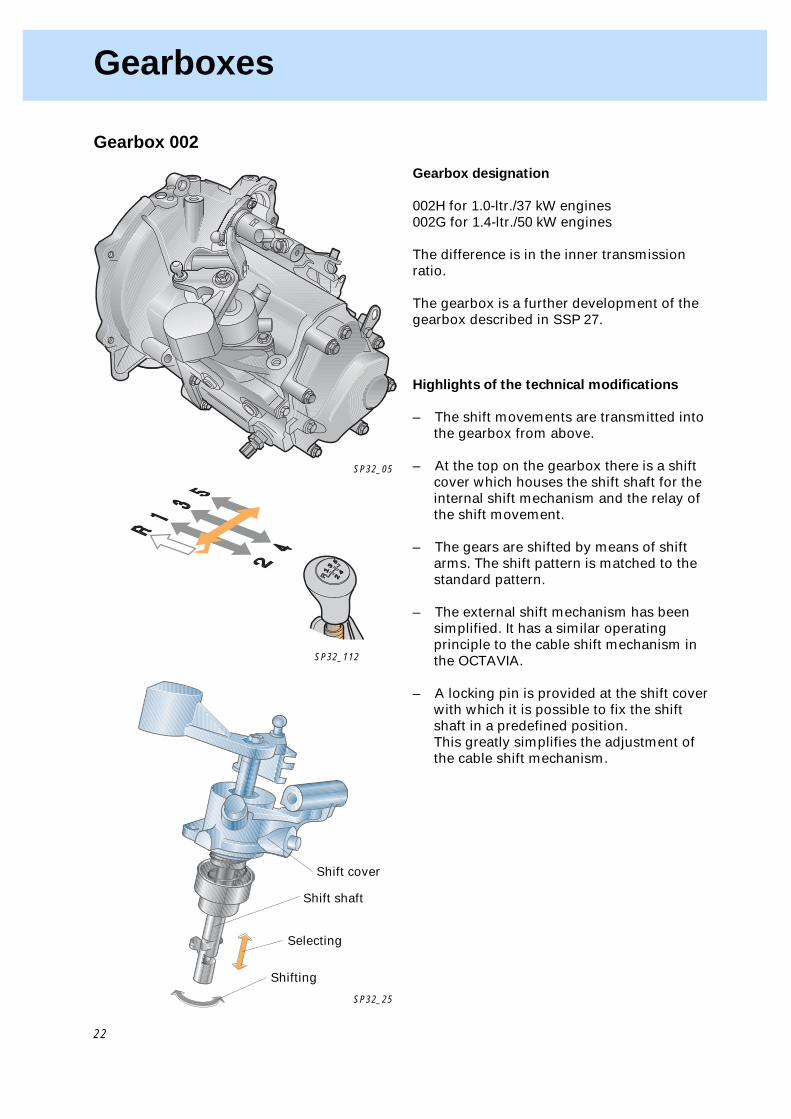
Highlights of the technical modifications
– The shift movements are transmitted into the gearbox from above.
– At the top on the gearbox there is a shift cover which houses the shift shaft for the internal shift mechanism and the relay of the shift movement.
– The gears are shifted by means of shift arms. The shift pattern is matched to the standard pattern.
– The external shift mechanism has been simplified. It has a similar operating principle to the cable shift mechanism in the OCTAVIA.
– A locking pin is provided at the shift cover with which it is possible to fix the shift shaft in a predefined position.This greatly simplifies the adjustment of the cable shift mechanism.
Gearbox 002
SP32_05
Shift cover
Shift shaft
SP32_25
Selecting
Shifting
R1
23
4
5
SP32_112

23
Engine/gearbox mounting
The engine/gearbox mounting is similar to the pendulum mounting (3-point mounting) familiar from the OCTAVIA.
The engine and gearbox mounts are positioned around the pivot axis of the power plant.
The pendulum support absorbs tensile and compressive forces.
The bearing mounting brackets are matched to the particular engine type.
Engine mount with mounting bracket
Gearbox mount with mounting bracket
Pendulum support
SP32_27
Selecting
Shifting
2
R1
35 4
Shift mechanism
The shift movement is transmitted from the shift lever into the gearbox by means of two cables in all the gearbox versions.
The principle used for relaying the shift movements from the hand shift lever to the gearbox shift lever is the same as that employed on the OCTAVIA.
SP32_26
SP32_28

24
Fuel System
Fuel tank
The following components are located directly at the fuel tank
– the fuel filter– the activated charcoal filter.
Both are connected to the fuel tank by flexible plastic lines.
The fuel pressure regulator is an integral part of the fuel filter. It is no longer positioned at the fuel rail of the engine.
The fuel tank is made of plastic. It holds approx. 45 litres.
Important!
Fuel tank,filler neck and2 expansion tanks (operating vent, refuelling vent)are a single unit.They cannot be separated.
The fuel delivery unit is located in the fuel tank.
Expansion tank (operating vent,
refuelling vent)
Fuel delivery unit
Fuel filter with pressure regulator
Fuel filler neck
Activated charcoal filter
SP32_30

25
M
Fuel tank vent system
Vent valve
SP32_45
Venting when refuelling
When the cap is removed, the vent valve automatically shuts off the vent line to the operating vent tank.
Fuel vapours from the fuel tank thus do not escape to atmosphere during refuelling.
The unleaded petrol flap is opened by the refuelling nozzle.
The air from the fuel tank is passed to the refuelling vent tank during refuelling and from there to the fuel filler neck.
Cap
Activated charcoal filter
Unleaded petrol flap
Vent line
Refuelling vent tank
Operating vent tank
Return-flow line, blue
Feed line, black
Fuel filter
to engine to engine
Gravity valve
In contrast to the predecessor version, the activated charcoal filter is not located in the left rear wheelhouse, but behind the wheelhouse liner behind the right rear wing.
Venting when driving
The unleaded petrol flap shuts off the filler neck by means of the spring tension. The cap on the filler neck pushes open the vent valve.
Fuel vapours which form as a result of the fuel warming up, flow into the operating vent tank.These vapours pass through the opened vent valve and the filler neck, which is sealed off to atmosphere, through the gravity valve to activated charcoal filter where they are bonded.
Refuelling nozzle

26
Fuel System
New!
SP32_31
SP32_32
Note:
The fuel injection system in engine has
been modified accordingly.
The engine now has a fuel rail through
which the fuel does not flow.
Fuel filter with pressure regulating
valve
Fuel filter and pressure regulating valve are a combined component.
This is positioned directly at the fuel tank and is divided into a spring chamber and a filter chamber.
The fuel pump pumps fuel into the filter chamber, the pressure regulating valve maintains the system pressure of 3 bar (0.3 MPa), which is effective in the fuel rail at the injectors.
The fuel is metered to the filter by means of an orifice plate in order to maintain the pressure.
If the pressure rises above 3 bar (0.3 MPa), the regulating valve to the spring chamber opens.
Excessive pumped fuel flows back along the shortest path unfiltered through the regulating valve into the fuel tank without having to take the long way round through the engine compartment.
Advantages:
This makes it possible to eliminate the return-flow line from the engine to the fuel tank. The fuel which flows back is warmed up less, the temperature in the fuel tank remains lower and the quantity of evaporating fuel is reduced.The fuel flowing back is not filtered. The service life of the filter is extended.
Spring chamber
Return flow to fuel tank
Regulating valve
Filter chamber
to engineFeed from fuel pump