ENGINEERING STANDARD FOR PROCESS DESIGN OF FANS
25
IPS-E-PR-755 This Standard is the property of Iranian Ministry of Petroleum. All rights are reserved to the owner. Neither whole nor any part of this document may be disclosed to any third party, reproduced, stored in any retrieval system or transmitted in any form or by any means without the prior written consent of the Iranian Ministry of Petroleum. ENGINEERING STANDARD FOR PROCESS DESIGN OF FANS AND BLOWERS ORIGINAL EDITION AUG. 1993 This standard specification is reviewed and updated by the relevant technical committee on Jul. 1998. The approved modifications are included in the present issue of IPS.
Transcript of ENGINEERING STANDARD FOR PROCESS DESIGN OF FANS
IPS-E-PR-755
This Standard is the property of Iranian Ministry of Petroleum. All rights are reserved to the owner. Neither whole nor any part of this document may be disclosed to any third party, reproduced, stored in any retrieval system or transmitted in any form or by any means without the prior written consent of the Iranian Ministry of Petroleum.
ENGINEERING STANDARD
FOR
PROCESS DESIGN OF FANS AND BLOWERS
ORIGINAL EDITION
AUG. 1993
This standard specification is reviewed and updated by the relevant technical committee on Jul. 1998. The approved modifications are included in the present issue of IPS.

Aug. 1993
IPS-E-PR-755
1
CONTENTS : PAGE No.
0. INTRODUCTION ............................................................................................................................. 2
1. SCOPE ............................................................................................................................................ 3
2. REFERENCES ................................................................................................................................ 3
3. DEFINITIONS AND TERMINOLOGY ............................................................................................. 3
4. SYMBOLS AND ABBREVIATIONS ............................................................................................... 5
5. UNITS .............................................................................................................................................. 6
6. GENERAL ....................................................................................................................................... 6
6.1 Fan Identification .................................................................................................................... 6
6.2 Pressure Limit of Application ................................................................................................ 6
6.3 Types of Fan ............................................................................................................................ 6
6.4 Performance ............................................................................................................................ 6
6.5 High Temperature Service ..................................................................................................... 6
7. DESIGN CRITERIA......................................................................................................................... 7
7.1 Selection Parameters of Process Fans................................................................................. 7
7.2 Operational Characteristics and Performance .................................................................... 7
7.3 Fan Laws .................................................................................................................................. 8
7.4 Performance Calculations...................................................................................................... 8
7.5 Fan Control ............................................................................................................................ 10
7.6 Fan Systems .......................................................................................................................... 11
7.7 Fan Selection Procedure ...................................................................................................... 11
7.8 Process Data Sheet............................................................................................................... 14
APPENDICES:
APPENDIX A Characteristic Curves for Radial, Backward and Forward Bladed Fans (Figs. A1-A5) and Performance Curves for Axial-Type Fans (Figs. A.6 & A.7)......... 16
APPENDIX B TABLE B.1 - TABLE OF FAN LAWS ................................................................... 18
APPENDIX C FAN SELECTION GUIDE CHART ....................................................................... 20
APPENDIX D EXAMPLES FOR FAN SELECTION..................................................................... 21
APPENDIX E TYPES OF FANS .................................................................................................... 24

Aug. 1993
IPS-E-PR-755
2
0. INTRODUCTION
"Pressure Reducing/Increasing Machineries and/or Equipment" are broad and contain variable subjects of paramount importance. Therefore, a group of process engineering standards are prepared to cover the subject.
This group includes the following standards:
STANDARD CODE STANDARD TITLE
IPS-E-PR-745 "Process Design of Vacuum Equipment (Vacuum Pumps & Steam Jet Ejectors)"
IPS-E-PR-750 "Process Design of Compressors"
IPS-E-PR-755 "Process Design of Fans and Blowers"
This Standard covers:
"Process Design of Fans and Blowers"
Basic process engineering calculation related to fans and blowers such as interpretation of performance curves, efficiency, power requirement, preparation of data sheets, etc. are presented.
As a general rule, all gas compressing equipment which produce less than 135 kPa(abs.) pressure at discharge, with an atmospheric (or slightly sub-atmospheric) suction pressure, fall into the category of "Fans and Blowers".
Process aspects of the blowers are discussed in IPS-E-PR-750. Therefore, this standard is dedicated to fans, in which, four most frequently used types, i.e., Centrifugal, Vaneaxial, Tubeaxial and propeller type are discussed.

Aug. 1993
IPS-E-PR-755
3
1. SCOPE
This Recommended Practice is intended to provide guidelines for process engineers for selection of proper type and preparation of process data sheets for fans used in O.G and P industries.
It contains basic reference information, data and formulas necessary for fan selection as mentioned above.
Note:
This standard specification is reviewed and updated by the relevant technical committee on Jul. 1998. The approved modifications by T.C. were sent to IPS users as amendment No. 1 by circular No 26 on Jul. 1998. These modifications are included in the present issue of IPS.
2. REFERENCES
Throughout this Standard the following dated and undated standards/codes are referred to. These referenced documents shall, to the extent specified herein, form a part of this standard. For dated references, the edition cited applies. The applicability of changes in dated references that occur after the cited date shall be mutually agreed upon by the Company and the Vendor. For undated references, the latest edition of the referenced documents (including any supplements and amendments) applies.
API (AMERICAN PETROLEUM INSTITUTE)
Standard No. 673 "Special Purpose Centrifugal Fans for Refinery Service" 1st. Ed., Jan. 1982
IPS (IRANIAN PETROLEUM STANDARDS)
IPS-E-GN-100, "Units"
IPS-E-PR-250, "Performance Guarantee"
IPS-M-PM-230, "Forced Draft Fans for Boilers and Process Services"
3. DEFINITIONS AND TERMINOLOGY
Terms used in this standard are defined as follows:
a) Fan impeller
Is the assembly of the fan wheel and the hub(s). (API Std. 673, Section 1.4).
b) Fan plane
Is a flow area perpendicular to the flow of gas at the specified reference plane; that is, inlet flange or outlet flange. (API Std. 673, 1.4).
c) Fan rated point
Is defined as (1) the highest speed necessary to meet any specified operating condition and (2) the rated capacity required by fan designs to meet all operating points. (The Vendor shall select this capacity point to the best encompass specified operating conditions within the scope of the expected performance curve.) (API Std. 673, 1.4).
d) Maximum continuous speed (rotations per minute) Is the speed at least equal to the product of 105 percent and the highest speed required by any of the specified operating conditions. (Modification to API Std. 673, 1.4).

Aug. 1993
IPS-E-PR-755
4
e) Normal operating point
Is the point at which usual operation. Is expected and optimum efficiency is desired. Unless otherwise specified, fan performance shall be guaranteed at the normal operating point. (API Std. 673, 1.4).
f) The total pressure (Ptf) of a fan
Is the rise of pressure from fan inlet to fan outlet as measured by two impact tubes, one in the fan inlet duct and one in the fan discharge duct, corrected for friction to the fan inlet and outlet respectively.
Where no inlet duct is used, total pressure on the inlet side is zero.
g) The velocity pressure (Pv) of a fan
Is the pressure corresponding to the average velocity determination from the volume of air flow at the fan outlet area.
h) The static pressure (Ps) of the fan
Is the total pressure (Ptf) diminished by the fan velocity pressure (Pv).
i) Standard air density
Is 1.2007 kg per cubic meter.
j) The unit of pressure
Is the mm. of water column of density of 997.423 kg per cubic meter and/or Pa (1 mm H2O conventional= 9.80665 pascals).
k) The volume handled by a fan
Is the number of cubic meters of air per hour expressed at fan outlet conditions.
l) The power output of a fan
Is expressed in kilowatts and is based on fan volume and fan total pressure.
m) The power input to a fan
Is expressed in kilowatts and is the measured kilowatt delivered to the fan shaft.
n) The mechanical efficiency of a fan
Is the ratio of power output to the power input.
o) The static efficiency of a fan
Is the mechanical efficiency multiplied by the ratio of the static pressure to the total pressure or es = et × Ps /Pt.
Aug. 1993
IPS-E-PR-755
5
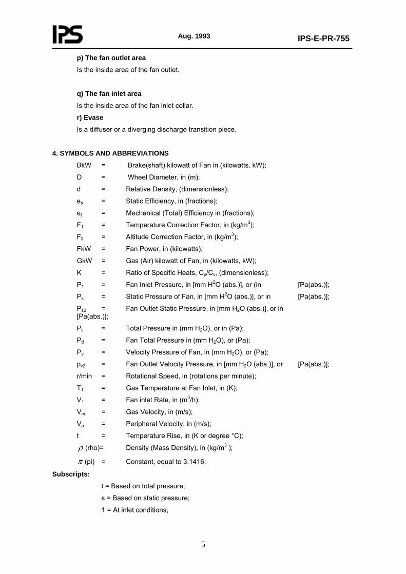
p) The fan outlet area
Is the inside area of the fan outlet.
q) The fan inlet area
Is the inside area of the fan inlet collar.
r) Evase
Is a diffuser or a diverging discharge transition piece.
4. SYMBOLS AND ABBREVIATIONS
BkW = Brake(shaft) kilowatt of Fan in (kilowatts, kW);
D = Wheel Diameter, in (m);
d = Relative Density, (dimensionless);
es = Static Efficiency, in (fractions);
et = Mechanical (Total) Efficiency in (fractions);
F1 = Temperature Correction Factor, in (kg/m3);
F2 = Altitude Correction Factor, in (kg/m3);
FkW = Fan Power, in (kilowatts);
GkW = Gas (Air) kilowatt of Fan, in (kilowatts, kW);
K = Ratio of Specific Heats, Cp/Cv, (dimensionless);
P1 = Fan Inlet Pressure, in [mm H2O (abs.)], or (in [Pa(abs.)];
Ps = Static Pressure of Fan, in [mm H2O (abs.)], or in [Pa(abs.)];
Ps2 = Fan Outlet Static Pressure, in [mm H2O (abs.)], or in [Pa(abs.)];
Pt = Total Pressure in (mm H2O), or in (Pa);
Ptf = Fan Total Pressure in (mm H2O), or (Pa);
Pv = Velocity Pressure of Fan, in (mm H2O), or (Pa);
pv2 = Fan Outlet Velocity Pressure, in [mm H2O (abs.)], or [Pa(abs.)];
r/min = Rotational Speed, in (rotations per minute);
T1 = Gas Temperature at Fan Inlet, in (K);
V1 = Fan inlet Rate, in (m3/h);
Vm = Gas Velocity, in (m/s);
Vp = Peripheral Velocity, in (m/s);
t = Temperature Rise, in (K or degree °C);
ρ (rho)= Density (Mass Density), in (kg/m3 );
π (pi) = Constant, equal to 3.1416;
Subscripts:
t = Based on total pressure;
s = Based on static pressure;
1 = At inlet conditions;

Aug. 1993
IPS-E-PR-755
6
2 = At outlet conditions.
5. UNITS
International System of Units (SI) in accordance with IPS-E-GN-100 shall be used.
6. GENERAL
6.1 Fan Identification
Fans are rather generally identified as machines with relatively low pressure rises which move air or gases or vapors by means of rotating blades or impellers and change the rotating mechanical energy into pressure or work on the gas or vapor. The result of this work on the fluid will be in the form of pressure energy or velocity energy, or some combination of both.
6.2 Pressure Limit of Application
Fans for all services handling air or gas, on process duties (excluding those for direct cooling or ventilating) and which develop less than 35 kPa (0.35 bar) from atmospheric pressure, shall conform to API Std. No. 673 (see 2.1), and Iranian Petroleum Standards IPS-M-PM-230, for " Forced Draft Fans for Boilers and Process Services."
6.3 Types of Fan
For types of fan refer to Appendix E of this Standard.
6.4 Performance
6.4.1 Fan performance shall be based on the static pressure differential across the fan inlet and outlet flanges. To obtain this differential, silencer and inlet losses, including control system losses, shall be added by the fan vendor to the purchaser’s specified inlet and outlet static pressures.(API Std. 673,2.1.6).
6.4.2 Performance curves shall have a continuous rising pressure characteristic from the rated point, as specified, to 60 percent or less of the rated flow. Performance curves, corrected for the specified gas at the specified conditions, shall be based on performance tests of actual or prototype equipment, including evase, if any, and inlet box(es). (API Std. 673,2.1.7).
6.4.3 Fan performance shall be guaranteed to meet all operating conditions specified on the data sheet and shall be within the tolerances listed, at the normal operating conditions.
a) For variable-speed fans, the static pressure and capacity shall be guaranteed with the understanding that the power shall not exceed +3%. These tolerances shall not be additive.
b) For constant-speed fans the specified capacity shall be guaranteed with the understanding that the static pressure shall be within +5% and -0% of that specified; the power shall not exceed stated power by more than +3%. These tolerances shall not be additive.
6.4.4 Fan performance shall be guaranteed in accordance with IPS Standard IPS-E-PR-250, "Performance Guarantee".
6.5 High Temperature Service
High temperature service for fans and auxiliaries is defined as a service for air and/or gas with a fan inlet temperature greater than 200°C. Fans, in this service will be indicated as "High temperature fans".

Aug. 1993
IPS-E-PR-755
7
7. DESIGN CRITERIA
7.1 Selection Parameters of Process Fans
This section of standard is intended to cover information necessary to determine the approximate power requirement and other selection parameters of process fans and to furnish proper data for evaluation of manufacturer’s proposals and/or preparation process data sheet.
7.2 Operational Characteristics and Performance
7.2.1 Centrifugal fans
The three types of centrifugal fan blades (radial, backward and forward) give three characteristic performances. Figures A.1 to A.5 of Appendix "A" present the typical characteristic curves for radial, backward and forward bladed fans respectively. Exact performance for a given fan can only be obtained on test.
a) Radial blade
This type of blade is usually used for handling suspended materials, abrasive dust collecting and exhausting of pumps from dirty, greasy or acid environment.
The rather sharply rising static pressure curve of the radial blade centrifugal fan allows for small changes in volume as the resistance of the system changes considerably.
A Fair running static efficiency is 50-70 percent for both the straight radial blade and radial tip blade.
b) Backward blade
This type of blade is well suited to stream line conditions and is used extensively on ventilating, air conditioning and clean and dirty process gas streams. The outstanding and important characteristic is the non-overloading power (kilowatts). It eliminates the need for oversized motors or other drivers. The usual operating static efficiency range for the regular blade is 65-80 percent and for the streamlined design is 80-92 percent.
c) Forward blade
This type is usually shallow and operates at slow speed for a given capacity and usually has low outlet velocity.
Its operating characteristics are poor for many applications, since the power rises sharply with a decrease in static pressure once the peak pressure for the fan has been reached. The operating static efficiency range is 55-75 percent.
7.2.2 Axial flow fans
The performance of the axial flow fan is represented in figures A.6 and A.7 of Appendix "A".
The power characteristic is non overloading. The usual pressure range of application is 0-76 mm water (0-745 pascals) static pressure. The vaneaxial and tubeaxial can be selected for higher outlet velocities than the centrifugal ( 10.2 - 20.3 m/s).
The axial fans should be connected to ducts by tapered cone connection. The peak efficiency range of the tubeaxial is 30-50 percent and for the vaneaxial is 40-65 percent.

Aug. 1993
IPS-E-PR-755
8
7.2.3 Propeller fans
These fans usually operate with no piping or duct work on either side, and move air or gas from one large open area to another. Pressures are usually very low and volumes depend upon size, blade pitch, number of blades and speed.
Static efficiencies run from 10-50 percent depending on the fan and its installation . With well designed inlet ring and discharge diffuser the efficiencies may be 50-60 percent.
7.3 Fan Laws
The performance of a fan is usually obtained from a manufacturer’s specific curve. Expected performance for a change from one condition of operation to another, or from one fan size to another is given in Table B.1 for geometrically similar fans. (Appendix B)
Fan laws apply to blowers, exhausters, centrifugal and axial flow fans. The relations are satisfactory for engineering calculations as long as the pressure rise is not greater than 7 kPa.
Theoretically a 100 mm H2O (0.98 kPa) pressure rise affects air density to cause a one percent deviation. Where greater accuracy is required, the familiar adiabatic power relations are used.
These laws are applicable only for geometrically similar fans and to the same point of rating on the performance curve.
7.4 Performance Calculations
7.4.1 Pressure
a) Total System Pressure
The sum of the static and velocity pressure is the "Total System pressure" , Pt.
Pt = Ps + Pv (Eq. 1)
Where:
Ps is static pressure
Pv is velocity pressure
The fan total pressure Ptf, (see 3, f) is measured as the increase in total pressure given to a gas passing through a fan. It is a measure of the total energy increase per unit volume imparted to the flowing gas by the fan. The static pressure is the fan total pressure than less the fan outlet velocity pressure, (see 3, h).
b) Velocity Pressure (see 3, g)
pv= 608.19
).( 2Vmo
mmof water (Eq.2)
or: pv= 2
).( 2Vmo
Pa (Eq.3)
Where:
ρ is gas density
Vm is gas velocity,
Aug. 1993
IPS-E-PR-755
9
Velocity pressure is indicated by a differential reading of an impact tube facing the direction of air flow in the fan outlet. It is a measure of the kinetic energy per unit volume of gas, existing at the fan outlet.
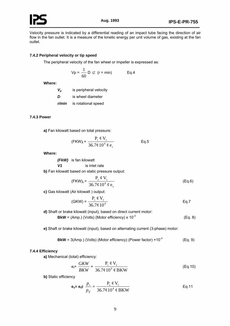
7.4.2 Peripheral velocity or tip speed
The peripheral velocity of the fan wheel or impeller is expressed as:
Vp = 601
D ⊄ (r = min) Eq.4
Where:
Vp is peripheral velocity
D is wheel diameter
r/min is rotational speed
7.4.3 Power
a) Fan kilowatt based on total pressure:
(FKW)t = t
41t
e ¢ 10 36.7¢V ¢ P
Eq.5
Where:
(FkW) is fan kilowatt V1 is inlet rate
b) Fan kilowatt based on static pressure output:
(FKW)s = s
41s
e ¢ 10 36.7¢V ¢ P
(Eq.6)
c) Gas kilowatt (Air kilowatt ) output:
(GKW) = 10 36.7¢
V ¢ P4
1t Eq.7
d) Shaft or brake kilowatt (input), based on direct current motor: BkW = (Amp.) (Volts) (Motor efficiency) x 10-3 (Eq. 8)
e) Shaft or brake kilowatt (input), based on alternating current (3-phase) motor:
BkW = 3(Amp.) (Volts) (Motor efficiency) (Power factor) ×10-3 (Eq. 9)
7.4.4 Efficiency
a) Mechanical (total) efficiency:
et= BKWGKW
= BKW ¢ 10 36.7¢
V ¢ P4
1t (Eq.10)
b) Static efficiency
es= et¢ tf
s
pp
= BKW ¢ 10 36.7¢
V ¢ P4
1s Eq.11
Aug. 1993
IPS-E-PR-755
10
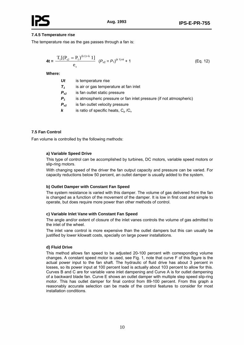
7.4.5 Temperature rise
The temperature rise as the gas passes through a fan is:
4t = s
k1)(k 1s21
e1] )P[(PT ==
(Pv2 = P1)(k 1)=k + 1 (Eq. 12)
Where:
Ut is temperature rise T1 is air or gas temperature at fan inlet Ps2 is fan outlet static pressure P1 is atmospheric pressure or fan inlet pressure (if not atmospheric) Pv2 is fan outlet velocity pressure k is ratio of specific heats, Cp /Cv
7.5 Fan Control
Fan volume is controlled by the following methods:
a) Variable Speed Drive This type of control can be accomplished by turbines, DC motors, variable speed motors or slip-ring motors. With changing speed of the driver the fan output capacity and pressure can be varied. For capacity reductions below 50 percent, an outlet damper is usually added to the system. b) Outlet Damper with Constant Fan Speed The system resistance is varied with this damper. The volume of gas delivered from the fan is changed as a function of the movement of the damper. It is low in first cost and simple to operate, but does require more power than other methods of control. c) Variable Inlet Vane with Constant Fan Speed The angle and/or extent of closure of the inlet vanes controls the volume of gas admitted to the inlet of the wheel. The inlet vane control is more expensive than the outlet dampers but this can usually be justified by lower kilowatt costs, specially on large power installations. d) Fluid Drive This method allows fan speed to be adjusted 20-100 percent with corresponding volume changes. A constant speed motor is used, see Fig. 1, note that curve F of this figure is the actual power input to the fan shaft. The hydraulic of fluid drive has about 3 percent in losses, so its power input at 100 percent load is actually about 103 percent to allow for this. Curves B and C are for variable vane inlet dampening and Curve A is for outlet dampening of a backward blade fan. Curve E shows an outlet damper with multiple step speed slip-ring motor. This has outlet damper for final control from 89-100 percent. From this graph a reasonably accurate selection can be made of the control features to consider for most installation conditions.

Aug. 1993
IPS-E-PR-755
11
COMPARISON OF EFFICIENCIES OF FIVE PRINCIPAL METHODS OF CONTROLLING FAN
OUTPUT
Fig. 1
7.6 Fan Systems
An operating fan is a part of some system. Regardless of the system, the fan cannot be selected until the flow and resistance characteristics have been analyzed. Fan selection for the system is based on the static pressure for a given volume of gas flowing. Since most fans operate at relatively low pressures the effect of uncertainty or error in resistance calculations can have a large percentage effect on Kilowatt and operational characteristics. Since it is essentially impossible to determine exact figures for the system resistances. It is to add 10-20 percent to the calculated static pressure as a safety factor.
7.7 Fan Selection Procedure
The following steps should be followed in fan selection.
7.7.1 Specifying the fan type
Informations presented in sections 6.3 and 7.2 may help in selecting the suitable fan for the process. Fan type curves should also be studied in order to recognize the effects of changes in system resistance on the fan performance and the volume and pressure changes caused by variations on speed. Recommendations of manufacturers are of particular importance in this stage.
Fig. C.1 of Appendix "C" may be used in fan type selection.
7.7.2 Specifying the inlet volume
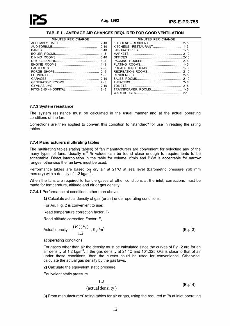
The volume of a fan should be determined by (1) the process material balance plus reasonable extra (about 20 percent) plus volume for control at possible future requirement, (2) generous capacity for purging, and (3) process area ventilation composed of fume hoods, heat dissipation and normal comfort ventilation. Table 1 gives suggested air changes for area ventilation, but not air conditioning.
Aug. 1993
IPS-E-PR-755
12
TABLE 1 - AVERAGE AIR CHANGES REQUIRED FOR GOOD VENTILATION MINUTES PER CHARGE MINUTES PER CHANGE
ASSEMBLY HALLS……………………………… 2-10 AUDITORIUMS……………………………………. 2-10 BANKS………………………………………………. 3-10 BOILER ROOMS…………………………………… 1- 5 DINING ROOMS……………………………………. 3-10 DRY CLEANERS…………………………………… 1- 5 ENGINE ROOMS………………………………….. 1- 3 FACTORIES………………………………………… 2- 5 FORGE SHOPS……………………………………. 2- 5 FOUNDRIES………………………………………… 1- 5 GARAGES…………………………………………… 2-10 GENERATOR ROOMS……………………………. 2- 5 GYMNASIUMS……………………………………… 2-10 KITCHENS – HOSPITAL………………………….. 2- 5
KITCHENS – RESIDENT…………………………… 2- 5 KITCHENS -RESTAURANT……………………… 1- 3 LABORATORIES…………………………………… 1- 5 MARKETS……………………………………………. 2-10 OFFICES ………………………………………………2-10 PACKING HOUSES………………………………… 2- 5 PLATING ROOMS…………………………………. 1- 5 PROJECTION ROOMS……………………………. 1- 3 RECREATION ROOMS…………………………… 2-10 RESIDENCES………………………………………. 2- 5 SALES ROOMS……………………………………. 2-10 THEATERS………………………………………….. 2- 8 TOILETS…………………………………………….. 2- 5 TRANSFORMER ROOMS………………………… 1- 5 WAREHOUSES……………………………………… 2-10
7.7.3 System resistance
The system resistance must be calculated in the usual manner and at the actual operating conditions of the fan.
Corrections are then applied to convert this condition to "standard" for use in reading the rating tables.
7.7.4 Manufacturers multirating tables
The multirating tables (rating tables) of fan manufacturers are convenient for selecting any of the many types of fans. Usually m3 /h values can be found close enough to requirements to be acceptable. Direct interpolation in the table for volume, r/min and BkW is acceptable for narrow ranges, otherwise the fan laws must be used.
Performance tables are based on dry air at 21°C at sea level (barometric pressure 760 mm mercury) with a density of 1.2 kg/m3 .
When the fans are required to handle gases at other conditions at the inlet, corrections must be made for temperature, altitude and air or gas density.
7.7.4.1 Performance at conditions other than above:
1) Calculate actual density of gas (or air) under operating conditions.
For Air, Fig. 2 is convenient to use:
Read temperature correction factor, F1
Read altitude correction Factor, F2
Actual dencity = 2.1
))(( 21 FF , Kg /m3 (Eq.13)
at operating conditions
For gases other than air the density must be calculated since the curves of Fig. 2 are for an air density of 1.2 kg/m3. If the gas density at 21 °C and 101.325 kPa is close to that of air under these conditions, then the curves could be used for convenience. Otherwise, calculate the actual gas density by the gas laws.
2) Calculate the equivalent static pressure:
Equivalent static pressure
) ty densi (actual
2.1 (Eq.14)
3) From manufacturers’ rating tables for air or gas, using the required m3/h at inlet operating
Aug. 1993
IPS-E-PR-755
13
conditions and the equivalent static pressure calculated in (2), read the r/min (rpm) and BkW. Interpolate if necessary.
4) The r/min is the correct value for the actual operating conditions.
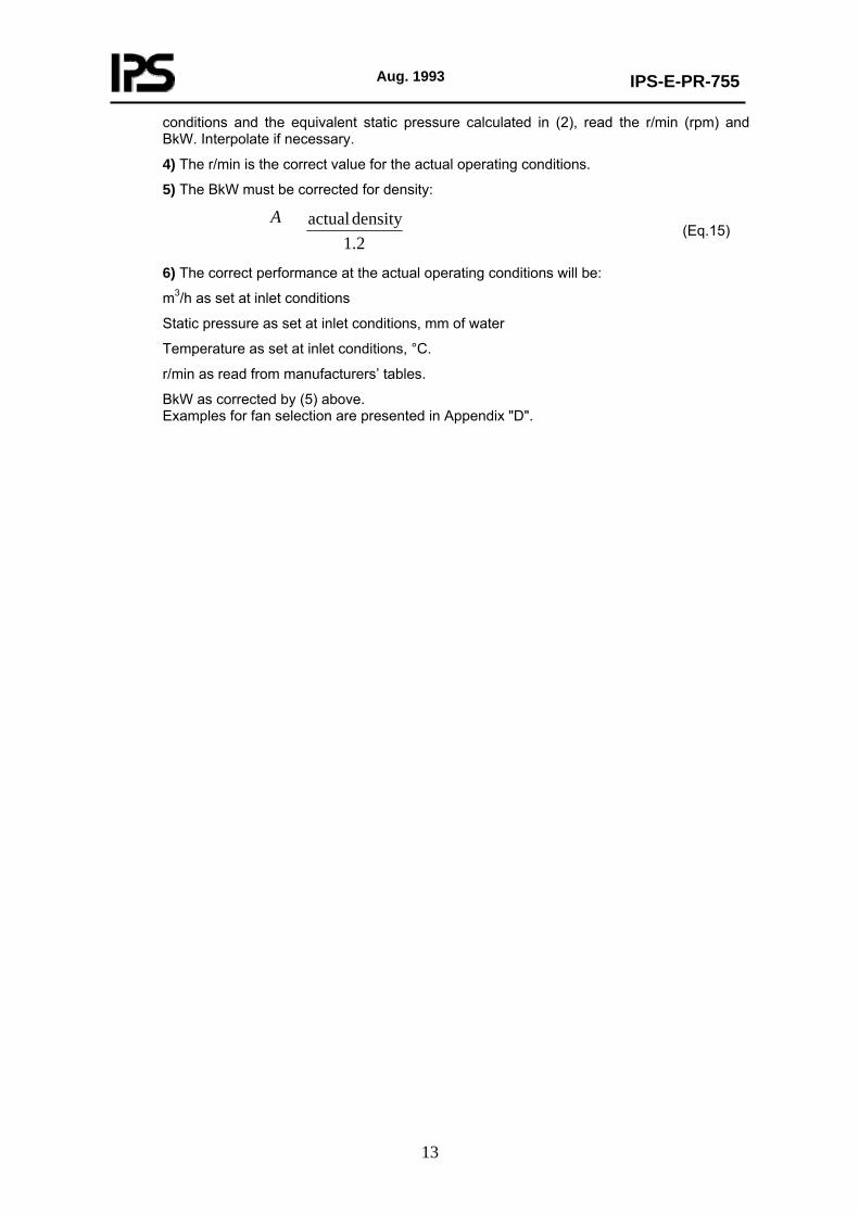
5) The BkW must be corrected for density:
2.1
density actualA (Eq.15)
6) The correct performance at the actual operating conditions will be:
m3/h as set at inlet conditions
Static pressure as set at inlet conditions, mm of water
Temperature as set at inlet conditions, °C.
r/min as read from manufacturers’ tables.
BkW as corrected by (5) above. Examples for fan selection are presented in Appendix "D".

Aug. 1993
IPS-E-PR-755
14
* Note: Conditions of air as defined in para. 7.7.4.
CORRECTION FACTORS FOR EFFECTS OF ALTITUDE AND TEMPERATURE ON AIR* Fig. 2
7.8 Process Data Sheet
The following data should be prepared by process engineer as the basic informations to be filled in data (specification) sheet;
a) Gas characteristics
b Air

Aug. 1993
IPS-E-PR-755
15
b Process gas; Name:
Composition:
Mol. Mass:
b) Operating conditions
Capacity, (dm3/s or kg/h)
Relative density, (Air = 1)
Barometric pressure, [m bar or mm H2O (abs.)]
Elevation above see level, meters (m)
Relative humidity, (%)
Inlet temperature (°C)
Inlet pressure [m bar or mm H2O (abs.)]
Outlet pressure [m bar or mm H2O (abs.)]
c) Control
b Outlet Dampers, (std.), (stream flow)
b Variable inlet vanes, (manual), (auto)
b Variable speed drive
b Slip ring motor
b Variable pitch blades
b Other
d) Fan Type
b Centrifugal
b Vaneaxial
b Tubeaxial
b Propeller
b Other

Aug. 1993
IPS-E-PR-755
16
APPENDICES
APPENDIX A
Characteristic Curves for Radial, Backward and Forward Bladed Fans (Figs. A1-A5) and Performance Curves for Axial-Type Fans (Figs. A.6 & A.7).
Characteristic curves Characteristic curves
for radial tip blade for backward curved blade
Fig. A.2 Fig. A.3
Characteristic curves Characteristic curves
for radial tip blade for full backward inclined flat blade
Fig. A.2 Fig. A.4
(to be continued)

Aug. 1993
IPS-E-PR-755
17
APPENDIX A(continued)
Performance curves for “streamlined” design of axial-type fans
Fig. A.7

Aug. 1993
IPS-E-PR-755
18
APPENDIX B
TABLE B.1 - TABLE OF FAN LAWS Variables * Normally
Constant ** Fan Law
Number
Ratio of
Ratio × Ratio
Ratio
a 1 b c
m3/h press.
Kw
=
size3 × (r/min) size2 × (r/min)2 size5 × (r/min)3
×
١d d
a 2 b c
m3/h r/min kW
=
size2 × press.1/2
1/size × press.1/2
size2 × press.3/2
×
١/d1/2
1/d1/2
1/d1/2
a 3 b c
r/min press.
KW
=
١/size3 × (m3/h) 1/size4 × (m3/h)2 1/size4 × (m3 /h)3
×
١d d
a 4 b c
m3/h press. r/min
=
size4/3 × kW1/31/size4/3 × kW2/3 1/size5/3 × kW1/3
×
١/d1/3
1/d1/3
1/d1/3
a 5 b c
size r/min kW
=
(m3/h)1/2 × 1/press.1/4
1/(m3/h)1/2 × press.3/4
(m3/h) × press.
×
d1/4
1/d1/4
1 a 6 b c
size press kW
=
(m3/h)1/3 × 1/(r/min)1/3
(m3/h)2/3 × (r/min)4/3
(m3/h)5/3 × (r/min)4/3
×
١d d
a 7 b c
size m3/h kW
=
press.1/2 × 1/(r/min) press.3/2 × 1/(r/min)2
press.5/2 × 1/(r/min)2
×
١/d1/2
1/d3/2
1/d3/2
a 8 b c
size r/min press.
=
١/kW1/4 × (m3/h)3/4
kW3/4 × 1/(m3/h)5/4
kW × 1/(m3/h)
×
d1/4
1/d3/4
1 a 9 b c
size r/min m3/h
=
kW1/2 × 1/press.3/4
1/kW1/2 × press.5/4
kW × press.
×
d1/4
1/d3/4
1 a 10 b c
size m3/h press
=
kW1/5 × 1/(r/min)3/5 kW3/5 × 1/(r/min)4/5
kW2/5 × (r/min)4/5
×
١/d1/5
1/d3/5
d3/5
(to be continued)
TABLE B.1 (continued) FOR CONSTANT AMOUNT BY MASS (SIZE CONSTANT). WHEN DENSITY OF AIR VARIES. 11 m3/h, r/min AND PRESSURE VARY INVERSELY AS THE DENSITY, THAT IS, INVERSELY AS THE BAROMETRIC PRESSURE AND DIRECTLY AS THE ABSOLUTE TEMPERATURE. ١٢ KILOWATT VARIES INVERSELY AS THE SQUARE OF THE DENSITY THAT IS INVERSELY AS THE SQUARE OF THE BAROMETRIC PRESSURE AND DIRECTLY AS THE SQUARE OF THE ABSOLUTE TEMPERATURE. FOR CONSTANT AMOUNT BY MASS (SIZE CONSTANT). WHEN BOTH TEMPERATURE AND PRESSURE VARY. 13 m3/h AND r/min VARY AS √ PRESSURE × ABSOLUTE TEMP. KILOWATT VARIES AS √ PRESSURE3 × ABSOLUTE TEMP.
* Either one of these variables may be used independently in which case the other must remain constant. Then the desired data will vary as power of the variable indicated. These laws are written as if both varied at the same time. In this case the desired data will vary as

Aug. 1993
IPS-E-PR-755
19
the powers of the variables indicated.
** In the last column the effect of relative density (d) is shown.
This is to apply as an extra variable when needed, otherwise density is supposed to be constant.

Aug. 1993
IPS-E-PR-755
20
APPENDIX C
FAN SELECTION GUIDE CHART
TYPICAL FAN SELECTION GUIDE CHART, BASED ON PRESSURE
RISE VERSUS AIR FLOW
Fig. C.1
Notes on Fig. C.1:
1) This chart shows the range of centrifugal and axial machines, and is based on catalogue ratings. The standard centrifugal ventilation fans operate approximately 560 mm of water. Beyond this, heavy-duty centrifugal fans, with higher compression ratios, may be made to specifications. The only area where no fan is available is above 2500 mm H2o at extremely low flows.
2) To use this graph: (1) calculate the actual m3/h at inlet conditions (at fan flange), and the total pressure rise-in mm of water-from the inlet to the discharge fan-flange; (2) locate the m3/h value on the chart; if the region where the point falls can be served by more than one type of fan (axial versus centrifugal, or different types of axial or centrifugal), decide on the type of fan by making economic and engineering evaluations.
Aug. 1993
IPS-E-PR-755
21
APPENDIX D
EXAMPLES FOR FAN SELECTION
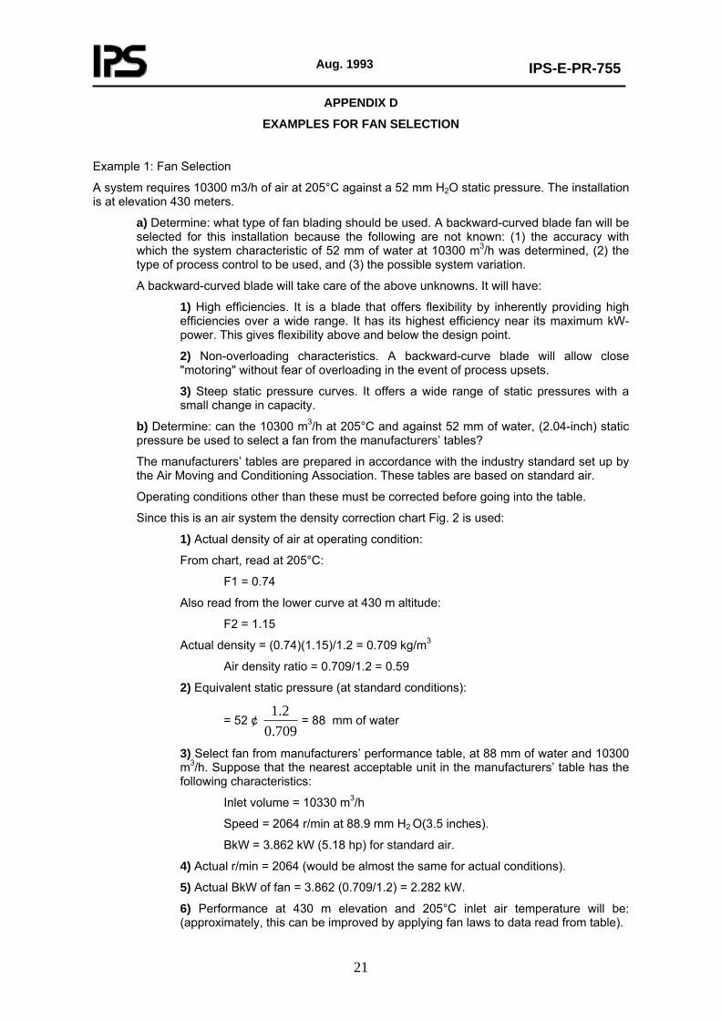
Example 1: Fan Selection
A system requires 10300 m3/h of air at 205°C against a 52 mm H2O static pressure. The installation is at elevation 430 meters.
a) Determine: what type of fan blading should be used. A backward-curved blade fan will be selected for this installation because the following are not known: (1) the accuracy with which the system characteristic of 52 mm of water at 10300 m3/h was determined, (2) the type of process control to be used, and (3) the possible system variation.
A backward-curved blade will take care of the above unknowns. It will have:
1) High efficiencies. It is a blade that offers flexibility by inherently providing high efficiencies over a wide range. It has its highest efficiency near its maximum kW-power. This gives flexibility above and below the design point.
2) Non-overloading characteristics. A backward-curve blade will allow close "motoring" without fear of overloading in the event of process upsets.
3) Steep static pressure curves. It offers a wide range of static pressures with a small change in capacity.
b) Determine: can the 10300 m3/h at 205°C and against 52 mm of water, (2.04-inch) static pressure be used to select a fan from the manufacturers’ tables?
The manufacturers’ tables are prepared in accordance with the industry standard set up by the Air Moving and Conditioning Association. These tables are based on standard air.
Operating conditions other than these must be corrected before going into the table.
Since this is an air system the density correction chart Fig. 2 is used:
1) Actual density of air at operating condition:
From chart, read at 205°C:
F1 = 0.74
Also read from the lower curve at 430 m altitude:
F2 = 1.15
Actual density = (0.74)(1.15)/1.2 = 0.709 kg/m3
Air density ratio = 0.709/1.2 = 0.59
2) Equivalent static pressure (at standard conditions):
= 52 ¢ 709.02.1
= 88 mm of water
3) Select fan from manufacturers’ performance table, at 88 mm of water and 10300 m3/h. Suppose that the nearest acceptable unit in the manufacturers’ table has the following characteristics:
Inlet volume = 10330 m3/h
Speed = 2064 r/min at 88.9 mm H2 O(3.5 inches).
BkW = 3.862 kW (5.18 hp) for standard air.
4) Actual r/min = 2064 (would be almost the same for actual conditions).
5) Actual BkW of fan = 3.862 (0.709/1.2) = 2.282 kW.
6) Performance at 430 m elevation and 205°C inlet air temperature will be: (approximately, this can be improved by applying fan laws to data read from table).
Aug. 1993
IPS-E-PR-755
22
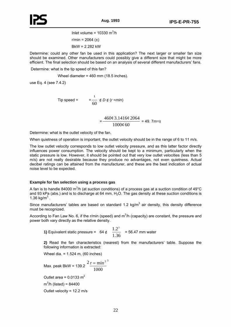
Inlet volume = 10330 m3/h
r/min = 2064 (±)
BkW = 2.282 kW
Determine: could any other fan be used in this application? The next larger or smaller fan size should be examined. Other manufacturers could possibly give a different size that might be more efficient. The final selection should be based on an analysis of several different manufacturers’ fans.
Determine: what is the tip speed of this fan?
Wheel diameter = 460 mm (18.5 inches).
use Eq. 4 (see 7.4.2)
Tip speed = =60¹
¢ D ¢ (r =min)
=60 1000¢
2064 3.1416¢ 460¢ = 49. 7m=s
Determine: what is the outlet velocity of the fan.
When quietness of operation is important, the outlet velocity should be in the range of 6 to 11 m/s.
The low outlet velocity corresponds to low outlet velocity pressure, and as this latter factor directly influences power consumption. The velocity should be kept to a minimum, particularly when the static pressure is low. However, it should be pointed out that very low outlet velocities (less than 5 m/s) are not really desirable because they produce no advantages, not even quietness. Actual decibel ratings can be attained from the manufacturer, and these are the best indication of actual noise level to be expected.
Example for fan selection using a process gas
A fan is to handle 84000 m3/h (at suction conditions) of a process gas at a suction condition of 49°C and 93 kPa (abs.) and is to discharge at 64 mm, H2O. The gas density at these suction conditions is 1.36 kg/m3 .
Since manufacturers’ tables are based on standard 1.2 kg/m3 air density, this density difference must be recognized.
According to Fan Law No. 6, if the r/min (speed) and m3/h (capacity) are constant, the pressure and power both vary directly as the relative density.
1) Equivalent static pressure = 64 ¢ 36.12.1 ±
= 56.47 mm water
2) Read the fan characteristics (nearest) from the manufacturers’ table. Suppose the following information is extracted:
Wheel dia. = 1.524 m, (60 inches)
Max. peak BkW = 139.2 33
1000minr2 =
Outlet area = 0.0133 m2
m3/h (listed) = 84400
Outlet velocity = 12.2 m/s
Aug. 1993
IPS-E-PR-755
23
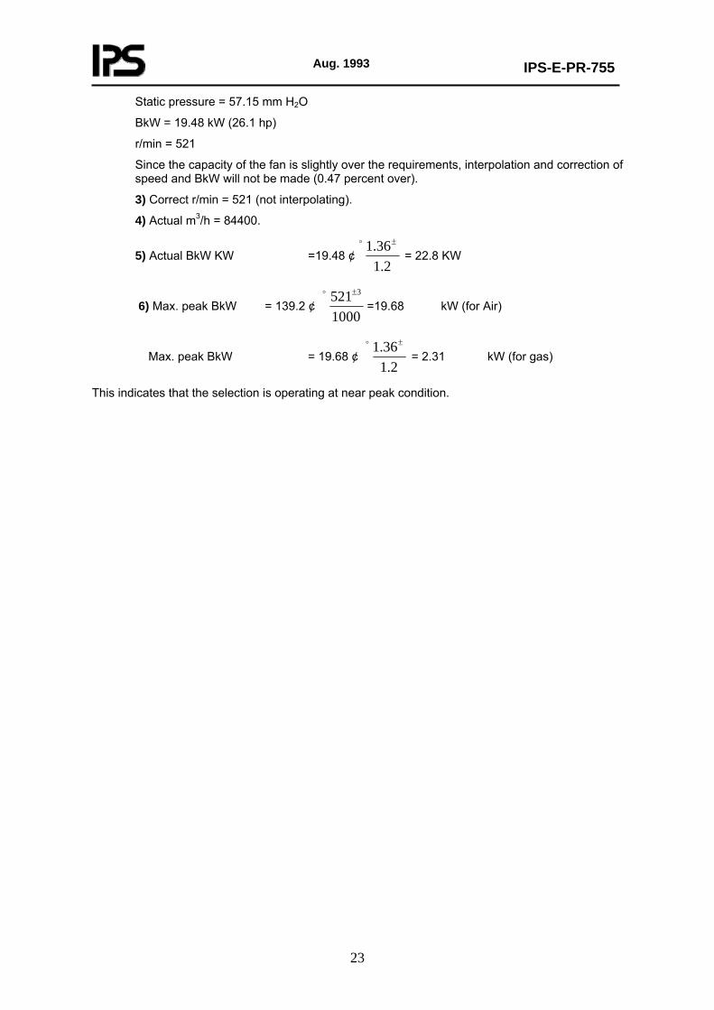
Static pressure = 57.15 mm H2O
BkW = 19.48 kW (26.1 hp)
r/min = 521
Since the capacity of the fan is slightly over the requirements, interpolation and correction of speed and BkW will not be made (0.47 percent over).
3) Correct r/min = 521 (not interpolating).
4) Actual m3/h = 84400.
5) Actual BkW KW =19.48 ¢2.1
36.1 ±o
= 22.8 KW
6) Max. peak BkW = 139.2 ¢ 1000521 3±o
=19.68 kW (for Air)
Max. peak BkW = 19.68 ¢ 2.1
36.1 ±o
= 2.31 kW (for gas)
This indicates that the selection is operating at near peak condition.

Aug. 1993
IPS-E-PR-755
24
APPENDIX E TYPES OF FANS
Ventilating and industrial fans are classified in four groups by the NAFM, National Association of Fan Manufacturers as described bellow (see Fig. E.1). E.1 A Centrifugal Fan consists of a fan rotor or wheel within a scroll type of housing. The centrifugal Fan is designed to move air or gases over a wide range of volume and pressures. The fan wheel may be furnished with straight, forward curve, backward curve, or radial tip blades. The fan housing may be constructed of sheet metal or cast metals with or without protective coating such as rubber, lead, enamel, etc. E.2 A Vaneaxial Fan consists of an axial flow wheel within a cylinder combined with a set of air guide vanes located either before or after the wheel. The Vaneaxial Fan is designed to move air or gases over a wide range of volumes and pressures. It is generally constructed of sheet metal although cast metal fan wheels are sometimes furnished. E.3 A Tubeaxial Fan consists of an axial flow wheel within a cylinder. The Tubeaxial Fan is designed to move air or gas through a wide range of volumes at medium pressures. Its construction is similar to the Vaneaxial Fan. E.4 A Propeller Fan consists of a propeller or disc wheel within a mounting ring or plate. The Propeller Fan is designed to move air from one enclosed space to another or from indoors to outdoors or vice versa in a wide range of volumes at low pressure. (The automatic type of shutter illustrated in cut opposite is not a part of the Propeller Fan but is an auxiliary device to protect the fan when not operating by keeping out wind, snow and cold).
CLASSIFICATION OF VENTILATING AND INDUSTRIAL FANS
Fig. E.1