Engineering Solid Mechanics - Growing ScienceO. Sam Daliri et al. / Engineering Solid Mechanics 7...
12
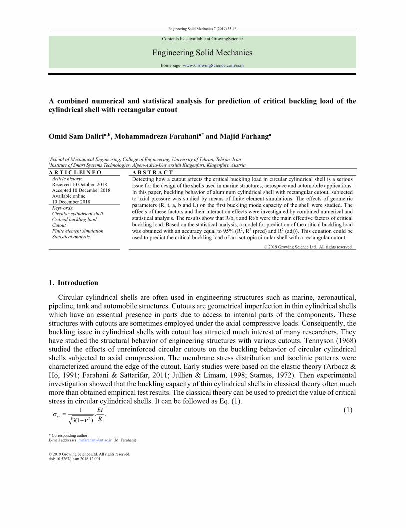
* Corresponding author. E-mail addresses: [email protected] (M. Farahani) © 2019 Growing Science Ltd. All rights reserved. doi: 10.5267/j.esm.2018.12.001 Engineering Solid Mechanics 7 (2019) 35-46 Contents lists available at GrowingScience Engineering Solid Mechanics homepage: www.GrowingScience.com/esm A combined numerical and statistical analysis for prediction of critical buckling load of the cylindrical shell with rectangular cutout Omid Sam Daliri a,b , Mohammadreza Farahani a* and Majid Farhang a a School of Mechanical Engineering, College of Engineering, University of Tehran, Tehran, Iran b Institute of Smart Systems Technologies, Alpen-Adria-Universität Klagenfurt, Klagenfurt, Austria A R T I C L EI N F O A B S T R A C T Article history: Received 10 October, 2018 Accepted 10 December 2018 Available online 10 December 2018 Detecting how a cutout affects the critical buckling load in circular cylindrical shell is a serious issue for the design of the shells used in marine structures, aerospace and automobile applications. In this paper, buckling behavior of aluminum cylindrical shell with rectangular cutout, subjected to axial pressure was studied by means of finite element simulations. The effects of geometric parameters (R, t, a, b and L) on the first buckling mode capacity of the shell were studied. The effects of these factors and their interaction effects were investigated by combined numerical and statistical analysis. The results show that R/b, t and Rt/b were the main effective factors of critical buckling load. Based on the statistical analysis, a model for prediction of the critical buckling load was obtained with an accuracy equal to 95% (R 2 , R 2 (pred) and R 2 (adj)). This equation could be used to predict the critical buckling load of an isotropic circular shell with a rectangular cutout. © 2019 Growing Science Ltd. All rights reserved. Keywords: Circular cylindrical shell Critical buckling load Cutout Finite element simulation Statistical analysis 1. Introduction Circular cylindrical shells are often used in engineering structures such as marine, aeronautical, pipeline, tank and automobile structures. Cutouts are geometrical imperfection in thin cylindrical shells which have an essential presence in parts due to access to internal parts of the components. These structures with cutouts are sometimes employed under the axial compressive loads. Consequently, the buckling issue in cylindrical shells with cutout has attracted much interest of many researchers. They have studied the structural behavior of engineering structures with various cutouts. Tennyson (1968) studied the effects of unreinforced circular cutouts on the buckling behavior of circular cylindrical shells subjected to axial compression. The membrane stress distribution and isoclinic patterns were characterized around the edge of the cutout. Early studies were based on the elastic theory (Arbocz & Ho, 1991; Farahani & Sattarifar, 2011; Jullien & Limam, 1998; Starnes, 1972). Then experimental investigation showed that the buckling capacity of thin cylindrical shells in classical theory often much more than obtained empirical test results. The classical theory can be used to predict the value of critical stress in circular cylindrical shells. It can be followed as Eq. (1). 2 1 . 3(1 ) cr Et R , (1)
Transcript of Engineering Solid Mechanics - Growing ScienceO. Sam Daliri et al. / Engineering Solid Mechanics 7...
* Corresponding author. E-mail addresses: [email protected] (M. Farahani) © 2019 Growing Science Ltd. All rights reserved. doi: 10.5267/j.esm.2018.12.001
Engineering Solid Mechanics 7 (2019) 35-46
Contents lists available at GrowingScience
Engineering Solid Mechanics
homepage: www.GrowingScience.com/esm
A combined numerical and statistical analysis for prediction of critical buckling load of the cylindrical shell with rectangular cutout
Omid Sam Daliria,b, Mohammadreza Farahania* and Majid Farhanga aSchool of Mechanical Engineering, College of Engineering, University of Tehran, Tehran, Iran bInstitute of Smart Systems Technologies, Alpen-Adria-Universität Klagenfurt, Klagenfurt, Austria
A R T I C L EI N F O A B S T R A C T Article history: Received 10 October, 2018 Accepted 10 December 2018 Available online 10 December 2018
Detecting how a cutout affects the critical buckling load in circular cylindrical shell is a serious issue for the design of the shells used in marine structures, aerospace and automobile applications. In this paper, buckling behavior of aluminum cylindrical shell with rectangular cutout, subjected to axial pressure was studied by means of finite element simulations. The effects of geometric parameters (R, t, a, b and L) on the first buckling mode capacity of the shell were studied. The effects of these factors and their interaction effects were investigated by combined numerical and statistical analysis. The results show that R/b, t and Rt/b were the main effective factors of critical buckling load. Based on the statistical analysis, a model for prediction of the critical buckling load was obtained with an accuracy equal to 95% (R2, R2 (pred) and R2 (adj)). This equation could be used to predict the critical buckling load of an isotropic circular shell with a rectangular cutout.
© 2019 Growing Science Ltd. All rights reserved.
Keywords: Circular cylindrical shell Critical buckling load Cutout Finite element simulation Statistical analysis
1. Introduction
Circular cylindrical shells are often used in engineering structures such as marine, aeronautical, pipeline, tank and automobile structures. Cutouts are geometrical imperfection in thin cylindrical shells which have an essential presence in parts due to access to internal parts of the components. These structures with cutouts are sometimes employed under the axial compressive loads. Consequently, the buckling issue in cylindrical shells with cutout has attracted much interest of many researchers. They have studied the structural behavior of engineering structures with various cutouts. Tennyson (1968) studied the effects of unreinforced circular cutouts on the buckling behavior of circular cylindrical shells subjected to axial compression. The membrane stress distribution and isoclinic patterns were characterized around the edge of the cutout. Early studies were based on the elastic theory (Arbocz & Ho, 1991; Farahani & Sattarifar, 2011; Jullien & Limam, 1998; Starnes, 1972). Then experimental investigation showed that the buckling capacity of thin cylindrical shells in classical theory often much more than obtained empirical test results. The classical theory can be used to predict the value of critical stress in circular cylindrical shells. It can be followed as Eq. (1).
2
1.
3(1 )cr
Et
R
, (1)
36
where E is the Young’s modulus, υ is the Poisson’s ratio, t is the shell thickness, R is the radius of the shell and cr is maximum critical stress. Eq. (1) estimate the critical stress in thin cylindrical shell having L/R≤5 without the cutout (Ugural, 1999). This value gives an upper bound to experimental results. Moreover, when R/t<50 shell may yield or collapse before the load reaches the estimated elastic buckling value (Chryssanthopoulos et al. 2000; Farahani et al., 2012). Bushnell (2012) reported both analytical and numerical studies and also conducted experimental investigations. It was reported that both analytical results and experimental results are extensively deviating. It was also reported that this deviation is due to the necessary differences called imperfections present in the real structure. There were many numerical and analytical researches that investigated the strength of the cylinders with certain imperfection shapes. Sonat et al. (2015) investigated the buckling of cylindrical metal shells. They proposed the agents of non-uniformity which leads to local shell buckling. Ifayefunmi (2016) studied buckling behavior for short cylindrs. Teng and Song (2001), Featherston (2003), Kim and Kim (2002), Farahani et al. (2013), Tripathi et al. (2016), and Khelil (2002), in their works took the first Eigen mode shape obtained from linear buckling analysis as imperfection shape and studied the buckling behavior of thin shell structures. Similarly, Pircher et al. (2001), Koiter (2001), Khamlichi et al. (2004), and Schneider (2006) used axisymmetric imperfection pattern extended over the entire length of the cylindrical shell and studied the buckling behavior of the shell structure. FE method is a suitable approach for buckling analysis of structures under axial force and thermal condition (Khechai et al., 2014). The effects of cutouts on the buckling behavior in thin cylindrical shells have investigated by few researchers. Jullien and Limam (1998) studied the effect of cutouts on the buckling of thin cylindrical shells subject to axial pressure. Yeh et al. (1999) analytically and experimentally studied the bending and buckling of moderately thick-walled cylindrical shells with cutouts. Tafreshi (2002) also numerically studied the buckling and post-buckling response of composite cylindrical shells subjected to internal pressure and axial pressure loads using ABAQUS. He studied the effects of size and orientation of cutouts and found that an increase of internal pressure resulted in an increase in buckling load. From the standpoint of the cutout shapes, rectangular, circular and elliptical cutouts are the utmost shapes that have been considered in buckling analysis of cylindrical shells (Dimopoulos & Gantes, 2012; Zargar et al., 2016; Guo et al. 2014; Han et al. 2006; Sankar & Parameswaran, 2016; Akbari et al., 2012; Vartdal et al. 2006a, 2006b). In all previous studies, there is no relation which could predict the critical buckling load of cylindrical shell including a cutout with acceptable accuracy. So achieving a formulation for prediction of buckling load of cylindrical shell with cutout is of great importance. Due to complications of the issue, none of the above mentioned researches have provided sufficient information to develop a parametric model for prediction of the critical buckling load. Furthermore, none of them have investigated the effect of the all geometric factors and their interaction effects on the buckling load. The aim of the present study is to investigate the effect of different geometric factors which have main effect on critical buckling load of the circular cylindrical shells with rectangular cutout. Thus, a combined model of numerical and statistical analysis is presented to estimate the critical buckling load of this structure accurately. The output model considered all main effective geometric factors of circular cylindrical shells with cutout.
2. Buckling analysis method Buckling instability occurs in elastic and plastic modes which can be made as local, overall or take place as combination of local and overall buckling. There are two types of buckling analysis. The first one is Eigen buckling analysis, known as bifurcation analysis, which estimates bifurcation load using linear elastic model in stiff structures. This technique refers to unlimited growth of deformation modes. In this analysis imperfections and nonlinearities cannot be included (Zhou et al. 2011; Sattari-Far & Farahani M, 2009). A linear buckling analysis is an Eigenvalue problem. It can be formulated as Eq. (2) in which [k] is stiffness matrix, λi is Eigenvalue for buckling mode, [s] is stress stiffness matrix and d shows the nontrivial solution for displacement.
O. Sam Daliri et al. / Engineering Solid Mechanics 7 (2019)
37
{ } {0}ik s d . (2)
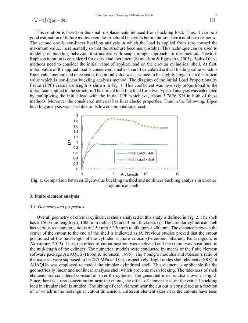
This solution is based on the small displacements induced from buckling load. Thus, it can be a good estimation of failure modes even the structural behaviors before failure have a nonlinear response. The second one is non-linear buckling analysis in which the load is applied from zero toward the maximum value, incrementally so that the structure becomes unstable. This technique can be used to model post buckling behavior of structures with snap through approach. In this method, Newton-Raphson iteration is considered for every load increment (Samuelson & Eggwertz, 2003). Both of these methods need to consider the initial value of applied load on the circular cylindrical shell. At first, initial value of the applied load is considered smaller than of calculated critical loading value which is Eigenvalue method and once again, this initial value was assumed to be slightly bigger than the critical value which is non-linear buckling analysis method. The diagram of the initial Load Proportionality Factor (LPF) versus arc length is shown in Fig. 1. This coefficient was inversely proportional to the initial load applied to the structure. The critical buckling load from two types of analysis was calculated by multiplying the initial load with the initial LPF which was about 3.78E6 KN in both of these methods. Moreover the considered material has liner elastic properties. Thus in the following, Eigen buckling analysis was used due to its lower computational cost.
Fig. 1. Comparison between Eigenvalue buckling method and nonlinear buckling analysis in circular
cylindrical shell 3. Finite element analysis 3.1. Geometry and properties Overall geometry of circular cylindrical shells analyzed in this study is defined in Fig. 2. The shell has a 1500 mm length (L), 1000 mm radius (R) and 3 mm thickness (t). The circular cylindrical shell has various rectangular cutouts of 150 mm × 150 mm to 400 mm × 400 mm. The distance between the center of the cutout to the end of the shell is indicated as H. Previous studies proved that the cutout positioned at the mid-length of the cylinder is more critical (Fereidoon, Shariati, Kolasangiani, & Akbarpour, 2013). Thus, the effect of cutout position was neglected and the cutout was positioned in the mid-length of the cylinder. The numerical models were conducted by means of the finite element software package ABAQUS (Hibbit & Sorensen, 1995). The Young’s modulus and Poisson’s ratio of the material were supposed to be 2E5 MPa and 0.3, respectively. Eight nodes shell elements (SR8) of ABAQUS was employed to model the circular cylindrical shell. This element is applicable for the geometrically linear and nonlinear analyses shell which prevents mesh locking. The thickness of shell elements are considered constant all over the cylinder. The generated mesh is also shown in Fig. 2. Since there is stress concentration near the cutout, the effect of element size on the critical buckling load in circular shell is studied. The sizing of each element near the cut out is considered as a fraction of 'a' which is the rectangular cutout dimension. Different element sizes near the cutouts have been
0
0.2
0.4
0.6
0.8
1
1.2
1.4
1.6
1.8
2
0 5 10 15
LPF
Arc Length
Initial Load = 4e6
Initial Load = 2e6

38
considered (a/10 ،a/20 and a/30). The effect of each refinement of the mesh on the critical buckling load is summarized in Table 1. The results showed that the mesh size smaller than a/20 had no significant effect on the critical buckling load, so in the following a ratio equal to a/20 was employed in simulations.
Fig. 2. Geometrical parameters of cylindrical shell with rectangular cutout
Table 1. The effect of mesh size near the cutout on the critical buckling load of the shell Mesh size a/10 a/20 a/30 Fcr × 103 [N] 246 246.1 246.1
3.2. Load and Boundary condition The axial compressive load was applied along the cylinder length at a reference point (RP) in a rigid surface on the top of the cylinder. This load is transferred uniformly to the top cylinder nodes as the RP and nodes on the top surface were coupled in axial direction. There are two types of boundary conditions (BCs), simply support and clamped support, commonly encountered. In this section, the effect of BCs on critical buckling load is simulated for two different sizes of cutout. The results are summarized in Table 2. As shown in Table 2, the two BCs at the bottom end of the circular shell have no significant effect on the critical buckling load. As a result, simply support BC is considered in the following as it is more close to the real BCs of an actual circular cylindrical shell. Table 2. Effect of BCs on the critical buckling load in cylindrical shell with rectangular cutout Cutout dimension (mm)
Fcr × 103 [N] Simple support Clamped support
150×150 246.1 246.2 400×400 101.21 101.25
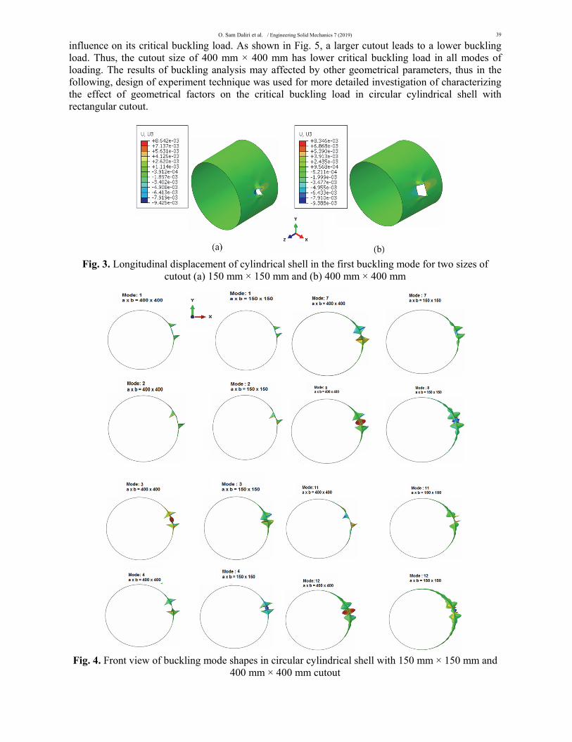
4. Buckling analysis of the shell with rectangular cutout The Finite element result for the circular cylindrical shell with a rectangular cutout is presented in this section. Fig. 3 shows the displacement behavior of shell in the first buckling mode in z-direction. Deformation shapes in the two studied shell with two different cutout dimensions are very similar. Different buckling mode shapes of the shell with various cutout sizes were also analyzed. Front view of selected various mode shapes are shown in Fig. 4. As illustrated in this figure, similar local buckling shape occurs in initial modes in both of the cutout. Regarding two sizes of cutout, critical buckling load are analyzed for numerous modes of shell by means of Eigenvalue method. In a circular cylindrical shell with a cutout positioned at its mid-height, a variation in the size of the cutout can remarkably
O. Sam Daliri et al. / Engineering Solid Mechanics 7 (2019)
39
influence on its critical buckling load. As shown in Fig. 5, a larger cutout leads to a lower buckling load. Thus, the cutout size of 400 mm × 400 mm has lower critical buckling load in all modes of loading. The results of buckling analysis may affected by other geometrical parameters, thus in the following, design of experiment technique was used for more detailed investigation of characterizing the effect of geometrical factors on the critical buckling load in circular cylindrical shell with rectangular cutout.
Fig. 3. Longitudinal displacement of cylindrical shell in the first buckling mode for two sizes of
cutout (a) 150 mm × 150 mm and (b) 400 mm × 400 mm
Fig. 4. Front view of buckling mode shapes in circular cylindrical shell with 150 mm × 150 mm and
400 mm × 400 mm cutout

40
Fig. 5. Critical buckling load at various buckling modes for two sizes of cutout
5. Combined numerical and statistical method The statistical analyses were used in this section in order to evaluate the effects of geometrical factors on the critical buckling load of the circular cylindrical shell with rectangular cutout. In another word, the result of this analysis was used to develop a model for predicting the buckling load magnitude which was a combining of numerical and statistical results. There are six geometric factors (R, t, a, b and L) as defined in Fig. 2 that may influence on the Eigenvalues. Among these parameters some have bigger effects on the critical buckling load, the others have smaller effects. As the cutout was considered at mid-length of the cylinder, so in this analysis the effect of H parameter on the Eigenvalues is neglected. When experiments involve a study of the effects of two or more factors, factorial designs are in general the most efficient for design of experiments (Chaloner & Verdinelli, 1995; Montgomery et al., 2012). In experimental design, each factor is set between high and low levels. The considered low and high levels of these factors are listed in Table 3. The levels should be defined wide as far as applicable to cover all desirable geometries. Table3. The employed range of geometric factors of cylindrical shell with a cutout Parameter R t a b L Low level 500 1.5 150 150 750 High level 1500 5 400 400 2000
To show the effect of each factor on Eigenvalue by using full factorial technique, sixteen
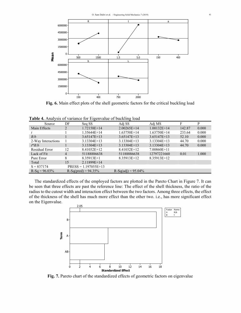
experiments were conducted considering two levels for each factor. The main effect of each factor on buckling load magnitude is depicted in Fig. 6. It can be seen in the plot that R and t have a positive impact whereas a, b and L have a negative impact on the critical buckling load. It means that the long cylindrical shell with bigger cutout size have lower Eigenvalues. In order to evaluate the effectiveness of the geometric factors on eigenvalue, a first order analysis of variance was conducted. In these analyses, accuracy of the model calculated based on the R-square and P-value (Montgomery, 2017). The P-value for R, t and b was very small, whereas this value for a and L was higher. It was found that both a and L factors have low effect on the critical buckling load, so, these two mentioned factors could be eliminated in modeling without significant changes in the accuracy. For more investigation, an analysis of variance was conducted with R, t and b parameters. The above results was confirmed by the obtained high accuracy about 96 percent (R2, R2(pred) and R2(adj)) of this analysis. In the following, the interaction between the mentioned three factors was studied (R/b, t/b and Rt/b). The result of variance analysis showed that when using the factors with t parameter, then R/b with t are the factors have the most influence on the Eigenvalue. The result is shown in Table 4.
0
1
2
3
4
5
6
7
8
0 5 10 15
F crx 1e6 [kN
]
Mode No.
150 x 150
400 x 400
O. Sam Daliri et al. / Engineering Solid Mechanics 7 (2019)
41
1500500
6000000
4500000
3000000
1500000
05.01.5 400150
400150
6000000
4500000
3000000
1500000
02000750
R
Mea
n
t a
b L
Fig. 6. Main effect plots of the shell geometric factors for the critical buckling load
Table 4. Analysis of variance for Eigenvalue of buckling load
Source DF Seq SS Adj SS Adj MS F P Main Effects 2 1.72158E+14 2.00265E+14 1.00132E+14 142.87 0.000 t 1 1.35644E+14 1.63750E+14 1.63750E+14 233.64 0.000R/b 1 3.65147E+13 3.65147E+13 3.65147E+13 52.10 0.000 2-Way Interactions 1 3.13304E+13 3.13304E+13 3.13304E+13 44.70 0.000 t*R/b 1 3.13304E+13 3.13304E+13 3.13304E+13 44.70 0.000Residual Error 12 8.41032E+12 8.41032E+12 7.00860E+11 Lack of Fit 4 51188886638 51188886638 12797221660 0.01 1.000 Pure Error 8 8.35913E+1 8.35913E+12 8.35913E+12 Total 15 2.11899E+14 S = 837174 PRESS = 1.197055E+13R-Sq = 96.03% R-Sq(pred) = 94.35% R-Sq(adj) = 95.04%
The standardized effects of the employed factors are plotted in the Pareto Chart in Figure 7. It can be seen that three effects are past the reference line: The effect of the shell thickness, the ratio of the radius to the cutout width and interaction effect between the two factors. Among three effects, the effect of the thickness of the shell has much more effect than the other two. i.e., has more significant effect on the Eigenvalue.
AB
A
B
181614121086420
Term
Standardized Effect
2.05
A R/bB t
Factor Name
Fig. 7. Pareto chart of the standardized effects of geometric factors on eigenvalue

42
The contour plot in Fig. 8 shows how R/b and t affect the Eigenvalue. The darker areas display higher Eigenvalues. The contour levels reveal that the maximum eigenvalue obtained for the highest R/b and t. The nonlinear relation between R/b and t was obvious in this contour.
R/b
t
1098765432
5.0
4.5
4.0
3.5
3.0
2.5
2.0
1.5
> – – – – < 2000000
2000000 40000004000000 60000006000000 80000008000000 10000000
10000000
Eigen
Fig. 8. Contour plot of Eigen versus t and R/b
According to nonlinear relation between R/b and t, in order to develop a model with high accuracy, new tests were designed by means of general factorial Design. Four levels is considered for R/b and t as listed in Table 5. The high and low level of the factors defined as Table 3. Table 5. The employed variable values in general factorial design factor levels R/b 1.25 3.75 7.08 10 t 1.5 2.67 3.83 5
The method of general factorial design is used to study the effect of new parameters of the shell on the critical buckling load. To see how the new factors (R/b and t) affect the Eigenvalue, the main effect plot are drown in Fig. 9. The main effect plot shows that Eigenvalue can be reduced by increasing the shell thickness and the ratio of the radius to the cutout width. Also, it is clear that shell thickness has uniform effect on the critical Eigenvalue whereas R/b has not uniform effect.
10.00007.08573.75001.2500
7000000
6000000
5000000
4000000
3000000
2000000
1000000
05.003.832.671.50
R/b
Mea
n
t
Fig. 9. Main effect plots of the R/b and t factors on the Eigenvalue
O. Sam Daliri et al. / Engineering Solid Mechanics 7 (2019)
43
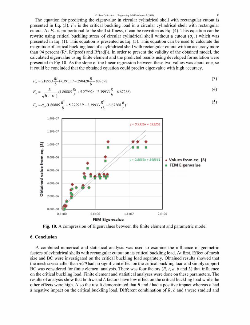
The equation for predicting the eigenvalue in circular cylindrical shell with rectangular cutout is presented in Eq. (3). Fcr is the critical buckling load in a circular cylindrical shell with rectangular cutout. As Fcr is proportional to the shell stiffness, it can be rewritten as Eq. (4). This equation can be rewrite using critical buckling stress of circular cylindrical shell without a cutout ( ) which was presented in Eq. (1). This equation is presented as Eq. (5). This equation can be used to calculate the magnitude of critical buckling load of a cylindrical shell with rectangular cutout with an accuracy more than 94 percent (R2, R2(pred) and R2(adj)). In order to present the validity of the obtained model, the calculated eigenvalue using finite element and the predicted results using developed formulation were presented in Fig 10. As the slope of the linear regression between these two values was about one, so it could be concluded that the obtained equation could predict eigenvalue with high accuracy.
218953 639111 290428 807698cr
Rt RF t
b b (3)
2(1.80885 5.27992 2.39933 6.67268)
3(1 )cr
E Rt RF t
b b
(4)
2 2
(1.80885 5.27992 2.39933 6.67268 ).cr cr
R R RF R
b t b t
(5)
Fig. 10. A compression of Eigenvalues between the finite element and parametric model
6. Conclusion
A combined numerical and statistical analysis was used to examine the influence of geometric
factors of cylindrical shells with rectangular cutout on its critical buckling load. At first, Effect of mesh size and BC were investigated on the critical buckling load separately. Obtained results showed that the mesh size smaller than a/20 had no significant effect on the critical buckling load and simply support BC was considered for finite element analysis. There was four factors (R, t, a, b and L) that influence on the critical buckling load. Finite element and statistical analyses were done on these parameters. The results of analysis show that both a and L factors have low effect on the critical buckling load while the other effects were high. Also the result demonstrated that R and t had a positive impact whereas b had a negative impact on the critical buckling load. Different combination of R, b and t were studied and
44
finally R/b and t specified as main effective factors of critical buckling load. New statistical analysis was conducted based on the new parameters (R/b and t) and their interaction effects were also considered. It was found that R/b, t and Rt/b could be used in final formulation for predicting the critical buckling load with high accuracy equal to 95 percent (R2, R2(pred) and R2(adj)). This formulation could be used for predicting the critical buckling load of isotropic cylindrical shell with a rectangular cutout.
Acknowledgement
The authors would like to thank the anonymous referees for constructive comments on earlier version
of this paper.
References Akbari, D., Farahani, M., & Soltani, N. (2012). Effects of the weld groove shape and geometry on
residual stresses in dissimilar butt-welded pipes. Journal of Strain Analysis for engineering design, 47, 73-82
Arbocz, J., & Ho, J. (1991). Collapse of axially compressed cylindrical shells with random imperfections. AIAA Journal, 29(12), 2247-2256.
Bushnell, D. (2012). Computerized buckling analysis of shells, Springer Science & Business Media. Chaloner, K., & Verdinelli, I. (1995). Bayesian experimental design: A review. Statistical Science,
10(3), 273-304. Chryssanthopoulos, M.K., Elghazouli, A.Y., & Esong, I.E. (2000). Validation of FE models for
buckling analysis of woven GFRP shells. Composite Structures, 49(4), 355-367. Dimopoulos, C.A., & Gantes, C.J. (2012). Experimental investigation of buckling of wind turbine
tower cylindrical shells with opening and stiffening under bending. Thin-Walled Structures, 54, 140-155.
Farahani, M., & Sattari-Far, I. (2011). Effects of residual stresses on crack-tip constraints. Scientia Iranica, 18(6), 1267–1276
Farahani, M., SattariFar, I., Akbari, D., & Alderliesten R. (2012). Numerical and experimental investigations of effects of residual stresses on crack behavior in Aluminum 6082-T6. Proceedings of the Institution of Mechanical Engineers, Part C: Journal of Mechanical Engineering Science, 226, 2178-2191
Farahani, M., SattariFar, I., Akbari, D., & Alderliesten R. (2013). Effect of residual stresses on crack behavior in single edge bending specimens. Fatigue & Fracture of Engineering Materials & Structures, 36, 115-126
Featherston, C. (2003). Imperfection sensitivity of curved panels under combined compression and shear. International Journal of Non-linear Mechanics, 38(2), 225-238.
Fereidoon, A., Shariati, M., Kolasangiani, K., & Akbarpour, A. (2013). Study on buckling of steel cylindrical shells with an elliptical cutout under combined loading. Journal of Computational and Applied Research in Mechanical Engineering, 3, 220-225.
Guo, S., Li, D., Zhang, X., & Xiang, J. (2014). Buckling and post-buckling of a composite C-section with cutout and flange reinforcement. Composites Part B: Engineering, 60, 119-124.
Han, H., Cheng, J., Taheri, F., & Pegg, N. (2006). Numerical and experimental investigations of the response of aluminum cylinders with a cutout subject to axial compression. Thin-Walled Structures, 44(2), 254-270.
Hibbit, K. (1995). Theory and User's Manual. Abacus manual, Rhode Island, USA. Ifayefunmi, O. (2016). Buckling behavior of axially compressed cylindrical shells: Comparison of
theoretical and experimental data. Thin-Walled Structures, 98, 558-564. Jullien, J.F., & Limam, A. (1998). Effects of openings of the buckling of cylindrical shells subjected to
axial compression. Thin-Walled Structures, 31(1), 187-202.
O. Sam Daliri et al. / Engineering Solid Mechanics 7 (2019)
45
Khamlichi, A., Bezzazi, M., & Limam, A. (2004). Buckling of elastic cylindrical shells considering the effect of localized axisymmetric imperfections. Thin-Walled Structures, 42(7), 1035-1047.
Khechai, A., Tati, A., & Guettala, A. (2014). Finite element analysis of stress concentrations and failure criteria in composite plates with circular holes. Frontiers of Mechanical Engineering, 9(3), 281-294.
Khelil, A. (2002). Buckling of steel shells subjected to non-uniform axial and pressure loading. Thin-Walled Structures, 40(11), 955-970.
Kim, S., & Kim, C. (2002). Buckling strength of the cylindrical shell and tank subjected to axially compressive loads. Thin-Walled Structures, 40(4), 329-353.
Koiter, W.T. (2001). Elastic stability and post-buckling behaviour. John Wiley & Sons. Montgomery, D.C. (2017). Design and analysis of experiments. John Wiley & Sons. Montgomery, D.C., Elizabeth, A., & Vining, G. (2012). Introduction to linear regression analysis. John
Wiley & Sons. Pircher, M., Berry, P.A., Ding, X., & Bridge, R.Q. (2001). The shape of circumferential weld-induced
imperfections in thin-walled steel silos and tanks. Thin-Walled Structures, 39(12), 999-1014. Samuelson, L.A., & Eggwertz, S.F. (2003). Shell stability handbook. CRC Press. Sankar, H., & Parameswaran, V. (2016). Effect of multiple holes on dynamic buckling of stubby shells:
An experimental and numerical investigation. International Journal of Impact Engineering, 96, 129-145.
Sattari-Far, I., & Farahani M. (2009) Effect of the weld groove shape and pass number on residual stresses in butt-welded pipes. International Journal of Pressure Vessels and Piping, 86, 723-731.
Schneider, W. (2006). Stimulating equivalent geometric imperfections for the numerical buckling strength verification of axially compressed cylindrical steel shells. Computational Mechanics, 37(6), 530-536.
Sonat, C., Topkaya, C., & Rotter, J. (2015). Buckling of cylindrical metal shells on discretely supported ring beams. Thin-walled Structures, 93, 22-35.
Starnes, J.H. (1972). Effect of a circular hole on the buckling of cylindrical shells loaded by axial compression. AIAA Journal, 10(11), 1466-1472.
Tafreshi, A. (2002). Buckling and post-buckling analysis of composite cylindrical shells with cutouts subjected to internal pressure and axial compression loads. International Journal of Pressure Vessels and Piping, 79(5), 351-359.
Teng, J.G., & Song, C.Y. (2001). Numerical models for nonlinear analysis of elastic shells with eigenmode-affine imperfections. International Journal of Solids and Structures, 38(18), 3263-3280.
Tennyson, R.C. (1968). The effects of unreinforced circular cutouts on the buckling of circular cylindrical shells under axial compression. Journal of Engineering for Industry, 90(4), 541-546.
Tripathi, S., Anup, S., & Muthukumar, R. (2016). Effect of geometrical parameters on mode shape and critical buckling load of dished shells under external pressure. Thin-Walled Structures, 106, 218-227.
Ugural, A. (1999). Stresses in plates and shells. McGraw-Hill. Vartdal, B.J., Al-Hassani, S.T.S., & Burley, S.J. (2006a). A tube with a rectangular cut-out. Part 1:
Subject to pure bending. Proceedings of the Institution of Mechanical Engineers, Part C: Journal of Mechanical Engineering Science, 220(5), 625-643.
Vartdal, B.J., Al-Hassani, S.T.S., & Burley, S.J. (2006b). A tube with a rectangular cut-out. Part 2: subject to axial compression. Proceedings of the Institution of Mechanical Engineers, Part C: Journal of Mechanical Engineering Science, 220(5), 645-652.
Yeh, M., Lin, M., & Wu, W. (1999). Bending buckling of an elastoplastic cylindrical shell with a cutout. Engineering Structures, 21(11), 996-1005.
Zargar, S.H., Farahani, M., & Besharati, M. (2016). Numerical and experimental investigation on the effects of submerged arc welding sequence on the residual distortion of the fillet welded plates. Proceedings of the Institution of Mechanical Engineers, Part B: Journal of Engineering Manufacture, 230(4) 654–661

46
Zhou, Z., Nishida, A., & Kuwamura, A. (2011). Applicability of finite element method to collapse analysis of steel connection under compression. Journal of Nuclear Science and Technology, 2, 481-485.
© 2018 by the authors; licensee Growing Science, Canada. This is an open access article distributed under the terms and conditions of the Creative Commons Attribution (CC-BY) license (http://creativecommons.org/licenses/by/4.0/).