Engineering Scale Up of Renewable Hydrogen Production by ... · ENGINEERING SCALE UP OF RENEWABLE...
16
ENGINEERING SCALE UP OF RENEWABLE HYDROGEN PRODUCTION BY CATALYTIC STEAM REFORMING OF PEANUT SHELLS PYROLYSIS PRODUCTS Robert J. Evans, Stefan Czernik, Esteban Chornet, Calvin J. Feik, Richard French, Steven D. Phillips National Renewable Energy Laboratory Golden, CO 80401 Abstract Renewable hydrogen may be produced in the near term at a cost that is competitive with natural gas reforming by integrating hydrogen production with existing industrial utilization of agricultural residues. A team of government, industrial, and academic organizations is developing a steam reforming process to be demonstrated on the gaseous byproducts from a process for making activated carbon from densified peanut shells [1]. The thermochemical user’s facility (TCUF) at NREL was the site for the initial shakedown of the scaled up reactor. It was interfaced with a 20-kg/hour fluidized-bed fast pyrolysis system to take advantage of process chemical analysis and computer control and monitoring capabilities. This paper reports the results from the shake down phase of this engineering demonstration project. After an initial problem with the heaters that required modification to the heater control strategy, the system passed mechanical shakedown tests and was integrated with the TCUF fluid bed pyrolysis system. The new control system developed to protect the reactor is based on 30 heater-monitoring thermocouples to prevent overheating in the case of heater malfunction. The 30-cm, catalytic, steam-reforming reactor was then successfully operated on methane and peanut shell pyrolysis products. Experiments with peanut pyrolysis vapor reforming duplicated the results in a 5-cm bench scale unit with the aqueous fraction of wood pyrolysis oil. This is the first time that the whole pyrolysis vapors have been processed in the fluid bed reforming process. Although peanut shells have a unique composition, containing high levels of lignin and protein, no problems were encountered in the reforming of the vapors. The only other significant problem uncounted was the plugging of the reformer distribution plate by fine char that acted as a nucleus for vapor deposition, slowly plugging the reactor. A hot gas filter was installed to remove the char and the reactor was operated for 30 hours without plugging The reformer has been shipped to the industrial site in Georgia where the shake down will continue with a 100 hours of run time. 1 Proceedings of the 2002 U.S. DOE Hydrogen Program Review NREL/CP-610-32405
Transcript of Engineering Scale Up of Renewable Hydrogen Production by ... · ENGINEERING SCALE UP OF RENEWABLE...

ENGINEERING SCALE UP OF RENEWABLE HYDROGEN PRODUCTION BY CATALYTIC STEAM REFORMING OF PEANUT
SHELLS PYROLYSIS PRODUCTS
Robert J. Evans, Stefan Czernik, Esteban Chornet, Calvin J. Feik, Richard French, Steven D. Phillips
National Renewable Energy Laboratory Golden, CO 80401
Abstract
Renewable hydrogen may be produced in the near term at a cost that is competitive with natural gas reforming by integrating hydrogen production with existing industrial utilization of agricultural residues. A team of government, industrial, and academic organizations is developing a steam reforming process to be demonstrated on the gaseous byproducts from a process for making activated carbon from densified peanut shells [1]. The thermochemical user’s facility (TCUF) at NREL was the site for the initial shakedown of the scaled up reactor. It was interfaced with a 20-kg/hour fluidized-bed fast pyrolysis system to take advantage of process chemical analysis and computer control and monitoring capabilities. This paper reports the results from the shake down phase of this engineering demonstration project. After an initial problem with the heaters that required modification to the heater control strategy, the system passed mechanical shakedown tests and was integrated with the TCUF fluid bed pyrolysis system. The new control system developed to protect the reactor is based on 30 heater-monitoring thermocouples to prevent overheating in the case of heater malfunction. The 30-cm, catalytic, steam-reforming reactor was then successfully operated on methane and peanut shell pyrolysis products. Experiments with peanut pyrolysis vapor reforming duplicated the results in a 5-cm bench scale unit with the aqueous fraction of wood pyrolysis oil. This is the first time that the whole pyrolysis vapors have been processed in the fluid bed reforming process. Although peanut shells have a unique composition, containing high levels of lignin and protein, no problems were encountered in the reforming of the vapors. The only other significant problem uncounted was the plugging of the reformer distribution plate by fine char that acted as a nucleus for vapor deposition, slowly plugging the reactor. A hot gas filter was installed to remove the char and the reactor was operated for 30 hours without plugging The reformer has been shipped to the industrial site in Georgia where the shake down will continue with a 100 hours of run time.
1
Proceedings of the 2002 U.S. DOE Hydrogen Program Review NREL/CP-610-32405

Introduction Biomass conversion is a near term source of renewable hydrogen if integrated with co-production opportunities that support economics of the overall process [2,3]. An array of feedstocks, conversion technologies, and co-products, are therefore possible under this overall concept as shown in figure 1. The goal of this project is the production of renewable hydrogen from agricultural residues, in the near-term time frame (~three years) and at a comparable cost to existing methane-reforming technologies. The production of hydrogen by the processing of pyrolysis products that are produced as a by-product of activated carbon is one possible path that demonstrates this co-product strategy.
- Biosolids- Animal waste- Sludges- Food wastes- MSW- Urban wood- Ag. residue- Forest waste- Energy crops- Designer crops
Conversion Technology
-Electricity- Fuelsethanolbiodiesel
- Chemicalshigh valueCO2
- Materialsbiopolymersbiobased
Feedstock Supply
Co-ProductMarkets
- Supercritical- Pyrolysis- Low pressure
gasification- High pressure
gasification-Storable inter.reforming:
ethanolmethanolmethane
Pyrolysis oil
+ +
Figure 1. Overall concept of integrating biomass to hydrogen with the production of co-products. NREL began the development of a biomass to hydrogen process in 1993 [2]. The original concept was that the pyrolysis oil could be fractionated into two fractions based on water solubility. The water-soluble fraction is to be used for hydrogen production and the water insoluble fraction could be used in adhesive formulations [4]. The bio-oil can be stored and shipped to a centralized facility where it is converted to hydrogen via catalytic steam reforming and shift conversion. Catalytic steam reforming of Bio-oil at 750-850ºC over a nickel-based catalyst is a two-step process that includes the shift reaction:
Bio-oil + H2O CO + H2
CO + H2O CO2 + H2
The overall stoichiometry gives a maximum yield of 17.2 g H/100 g bio-oil (11.2 wt.% based on wood).
2
Proceedings of the 2002 U.S. DOE Hydrogen Program Review NREL/CP-610-32405

CH1.9 O0.7 + 1.26 H2O CO2 + 2.21 H2
Regional networks of pyrolysis plants could be established to provide oil to a central steam reforming facility. The process is adaptable to other organic waste streams such as aqueous-steam fractionation processes used for ethanol production, pyrolysis oil fractions from different feedstocks, glycerine from biodiesel production, and trap grease [5].
This approach has the potential to be cost-competitive with current commercial processes for hydrogen production. The process has been demonstrated at the bench scale using model compounds and the carbohydrate-derived fraction of bio-oil [2,6]. Although this option remains viable, commercial deployment opportunities for hydrogen linked to the adhesives co-products are still not near term. Hence, other opportunities had to be developed based on the co-product strategy. The conversion of biomass to activated carbon is an alterative route to hydrogen with a valuable co-product as outlined in figure 2. Slow pyrolysis is used in the first step of the activated carbon process to maximize the yield of charcoal and organic vapors are produced as a by-product in 25% yield. Southwest Georgia was identified as an excellent opportunity because of the importance of agriculture, the forest product industry and the need for zero emission transportation fuels in the Atlanta area. Scientific Carbons Inc. in Blakely GA uses pelletized peanut shells as the feed material for the production of activated carbon. They feed up to 1000 kg/hour of the densified peanut shells to a two-stage process producing activated carbon. The vapor by-products from the first stage, pyrolysis, are currently used as fuel for steam generator.
Slow Pyrolysis
FBR CatalyticReforming
Biomass[100]
crude bio-oilwater [30]organic [25]Gases [10]
Char [35]
Steam [15]
H2 [6.7]CO2 [60]CO [13]
Steam [8]
H2 [7.6]CO2 [81]
Shift Conversion
ActivationCarbon[15]
Other [20]
Activated
Figure 2. Mass Balance and unit operations in the slow pyrolysis of biomass to activated carbon and hydrogen A team of organizations led by Clark Atlanta University [1] submitted a successful proposal to the U.S. DOE’s Hydrogen Program to demonstrate the steam reforming process of the pyrolysis vapors to produce hydrogen over a three-year period. The Scientific Carbons Inc. facility in Blakely, Georgia will be used as the development site as described elsewhere in these proceedings.
3
Proceedings of the 2002 U.S. DOE Hydrogen Program Review NREL/CP-610-32405

Catalyst performance is promising with run times in a two-inch fluid bed reactor of over 100 hours. Systematic studies of variation in catalyst composition have shown that commercial steam reforming catalysts perform optimally for the conversion [7]. However, physical attrition is a problem since these catalysts are not manufactured for fluid bed operation. Losses of approximately 5% per day of operation have been reported in the small reactor [6]. The FY2002 objectives are: • Scale up catalytic steam reforming process parameters as derived from the bench scale
experimentation carried out at NREL to develop the process concept. • Determine gas composition over the catalyst life cycle and compare to the purity
requirements needed for the shift reactors and pressure swing adsorption unit. This will be performed at NREL using the Thermochemical Users Facility (TCUF). NREL’s available analytical capabilities of TCUF will allow the process gas stream to be characterized and optimized for the subsequent operation at the Scientific Carbons plant in Georgia.
• Participate in the Phase 2 testing work that will occur in Georgia at the Scientific Carbons site.
• Support the partnership development that will be necessary for the bus demonstration. And identify other biomass resources in the region that could be used to produce hydrogen.
This paper reports on the design, set up, and shake-down of the scaled-up catalytic steam reforming reactor and on the initial tests for conversion of whole biomass pyrolysis vapors to hydrogen. The thermochemical user’s facility is designed to assist bioenergy technology developers test thermochemical process concepts by interfacing key unit operations in the existing TCUF facility. This approach minimizes risk and disruption by taking advantage of process control systems and analytical capabilities, which would not be available for shakedown or proof of concept in an industrial environment. By performing the initial system tests at NREL, the experience of the NREL researchers with the process and the analytical equipment of TCUF can be used to monitor and optimize the system performance. The 20-kg/hr fluid bed pyrolysis unit at TCUF was used to feed the steam-reforming unit for the shakedown.
Duplicate 1 Duplicate 2% Extractives 14.4 13.9
% Ash 3.4 3.4% Lignin 33.9 35.7
% Glucan 20.7 21.4% Xylan 7.5 8.2
% Galactan 0.1 0.2% Arabinan 0.6 0.7% Mannan 0.1 0.1% Protein 11.1 11.1
Experimental
Pelletized peanut shells obtained from the Birdsong peanut processing plant in Blakely, GA, were fed to a 20 cm fluid bed pyrolysis reactor. An in-line grinder was used to reduce the particle size to that required for fluid bed operation. Table 1 shows the compositional analysis on the feedstock that has been performed to date. The mass closure on the two replicates was an average of about 93%, and work is in progress to identify the remaining 7%. The lignin values are exceptionally high compared to other biomass feedstocks. The ultimate analysis results were: 46 % carbon,6.3% hydrogen, 2.0% nitrogen, 0.17% sulfur, and 0.17% Cl.
Table 1. Chemical analysis of peanut shells used in fluid bed run
4
Proceedings of the 2002 U.S. DOE Hydrogen Program Review NREL/CP-610-32405

The schematic of the experimental system is shown in figure 3. Superheated steam, at a mass ratio of 1:1 steam to feed, was used to fluidize both the pyrolysis fluid bed and the steam reforming fluid bed and also as a reactant in the reformer. From 5-20 kg/hour of pelletized peanut shells was fed into a 20 cm fluidized bed of 300-400 µM sand at 550 oC. A thermal cracker, which is used for studying gas phase reactions, was normally kept at 500 oC, and at 1 sec residence time, functioned as a transfer tube. One series of experiments were performed to see what effect gas phase cracking of the pyrolysis vapor had on reforming efficiency and the vapor cracker was varied from 500 to 750 oC. Char is next separated in two cyclones in series. In the first series of tests, the steam/vapor stream then enters a preheater that raises its temperature to 650-700°C. Fine particles of char that were not captured by the cyclones eventually led to plugging problems (described in Results and Discussions) so a hot gas filter, not shown in fig. 3, was installed between the cyclones and the preheater. In consisted of 4 stainless steel filtering elements with the capability for back pulsing to remove the filtered mass from the filter elements.
Figure 3. Process Flow Sheet for the Shake down of the Steam Reforming Reactor in the Thermochemical Process Development Unit. The catalytic fluid bed reformer was designed and constructed with the basic engineering design based on past results with the bench-scale, fluid-bed reactor. A schematic and photograph of the reformer are shown in Figure 4. The reactor was designed to process 7-10 kg/h of pyrolysis vapor. The maximum allowable operating temperature and pressure are 900 oC and 140 kPa, respectively. The reformer is equipped with fluid bed reactor, vapor and liquid feed injection, steam (and O2) injection, internal and external cyclones for disengaging catalyst particles. The cyclones capture both fine catalyst particles and solid carbon generated by gas phase pyrolysis of the vapors that may occur in competition with the catalytic steam reforming. The Inconel reactor with a porous material distribution plate is placed inside a three zone electric furnace.
5
Proceedings of the 2002 U.S. DOE Hydrogen Program Review NREL/CP-610-32405

Figure 4. The Catalytic Fluid Bed Steam Reforming Reactor.
Commercial nickel-based catalyst ground to a particle size of 300-500 µ is being used in the reactor. Since the catalyst is not available in a form suitable for a fluid bed, it was commissioned from Shd-Chemie (formerly United Catalysts) who prepared the required size fraction from grinding a catalyst used for packed bed methane steam reforming. The catalyst is fluidized using superheated steam, which is also a reactant in the reforming process. The exit gas from the reformer goes to the scrubber unit where two spray condensers are used in series followed by a cold wall heat exchanger. Recirculating water is used for scrubbing the fine catalyst particles as well as entrained carbonaceous material, tars, HCl, and NH3. The gas then passes through a coalescing filter to remove aerosols. A slip-stream of the dry gas then goes to a series of non-dispersive IR detectors for CO2, CO, and CH4 monitoring and a and thermal conductivity hydrogen detector. The gas then is analyzed by a rapid-cycling gas chromatograph (MTI) allowing more detailed product analysis. Hot gas sampling ports both before and after the reformer are used for periodic sampling of the gas stream. The hot slip stream passes to a collection train consisting of an electrostatic precipitator and a condenser in series. The samples before the reformer would phase separate into an aqueous layer and a tar phase. The unit was then rinsed with acetone. The hot gases were also analyzed by molecular beam mass spectrometry [8] to provide analysis of the organic vapors, especially the aromatics, which are of concern, since a filtering system will have to be designed to remove those that escape from the reformer because of the impact on subsequent processing steps when commercially practiced, such as the water-gas shift catalyst system and the pressure swing adsorption units.
6
Proceedings of the 2002 U.S. DOE Hydrogen Program Review NREL/CP-610-32405

The reformer is run in three modes: catalyst activation, reforming, and catalyst regeneration. The typical start-up procedure was as follows: 1. Heat up the pyrolyzer to 550o C and reformer to 300o C with N2 flowing. 2. Fluidize both pyrolyzer and reformer beds when the reformer reaches 300o C with N2. 3. Increase reformer temperature to 850o C and flow H2 until adsorption stops (catalyst
reduction). 4. Switch from N2 to steam at 10 kg/hour. H2 flow is maintained until methane or biomass is
fed to prevent catalyst oxidation by the steam. 5. Begin to feed peanut shells at 5 kg/hour and when reformed products are observed stop
added hydrogen. 6. Incrementally increase steam and feed to the target conditions (e.g., 20 kg/hour each),
insuring that reformer bed temperatures remain within set points.
Results and Discussion Installation and Shakedown of the Reactor at NREL The composition of the pyrolysis products from the fluid bed system was unexpected. The char yield for this run was high (~32%) and due to the high ash content, which catalyzes char formation from carbohydrates, and high lignin and protein content, both of which produce char yields of 30%. Studies in the laboratory showed that, even with small particle size and high temperature, the char yields were a minimum of 25% under conditions where wood char yields would be 12%. On-line, Molecular Beam Mass Spectrometry (MBMS) [8] was used to monitor pyrolysis vapor composition and compare to more conventional biomass feedstocks such as wood and herbaceous species. The MBMS analysis of the pyrolysis products being fed to the reformer is shown in figure 5. This is a major change from the expected primary pyrolysis product distribution that is obtained in bench scale laboratory equipment. Relatively high yields of methane, m/z 16, and carbon dioxide, m/z 44, were observed (CH4 yield is ~2 wt.% versus 0.2% in more typical primary product yields). The high methane value is confirmed by the conventional gas analysis shown in Table 2 (values were normalized to a nitrogen free basis). We suspect that the product slate may be influenced by the accumulating char inventory in the fluid bed. Higher molecular products are dominated by the lignin-derived phenolics (m/z 94,108,124, 138 and 150 and fatty acid pyrolysis products at m/z 256,264,280. The high ash content of the feed probably diminishes higher molecular weight carbohydrate derived products [8]. Reactor Shakedown: Reforming of Methane A conservative approach was taken to the initial heat up and testing of the reformer to minimize the change of damage occurring. The reactor was brought up to 850 C slowly after fluidizing the bed at 300 C. Even at 850 C, the twelve-heater surface monitoring thermocouples did not note any deviations larger than 100 C so the expected cause of the wall failure, namely a large difference between the monitoring location and the region where the failure occurred was not observed. Although this was a comforting observation, it weakened our explanation of the problem. The heater section was replaced so it may have been due to that particular heater rather than a design problem. In any case, it did not seem likely that the problem was caused by the way the reactor was operated although a slow heat up is a good idea. The initial tests with methane were to verify the physical design allowed good gas catalyst interactions and to test that the heater system is capable to produce the required heat of reaction for the endothermic methane reforming reaction. Methane was introduced at 25% of the design capacity and slowly increased to the level equivalent to 7 kg/hour of pyrolysis oil.
7
Proceedings of the 2002 U.S. DOE Hydrogen Program Review NREL/CP-610-32405

Table 2. Average pyrolysis product gas composition, vol. %, N2 free basis.
Figure 5. MBMS Spectrum of fluid bed pyrolysis products from on-line MBMS analysis Reactor Shakedown: Reforming of Peanut Shell Pyrolysis Vapors
44
16
0
20000
40000
60000
80000
100000
120000
140000
160000
0 25 50 75 100 125 150 175 200 225 250 275 300 325 350
m/z
Inte
nsity
(Arb
itrar
y U
nits
)
94
256264
280
108 124 138
150
75 125 175 225 275 325
H2 15.7CH4 17.5Carbon Monoxide 18.7CO2 41.8ethylene 1.8ethane 2.0acetylene 0.0propane 1.9propylene 0.11-butene 0.5trans-2-butene 0.1
After the test with methane it was next interfaced with the pyrolysis fluid bed reactor. The feed rate was increased from 5 to 10 kg/hr and the objective was to observe the mechanical performance of both systems. Figure 6 shows process variables for a typical 6 hour run showing a feed rate of 10 kg/hour of biomass. The other two curves show the pressure of
8
Proceedings of the 2002 U.S. DOE Hydrogen Program Review NREL/CP-610-32405
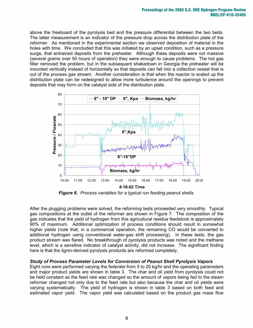
above the freeboard of the pyrolysis bed and the pressure differential between the two beds. The latter measurement is an indicator of the pressure drop across the distribution plate of the reformer. As mentioned in the experimental section we observed deposition of material in the holes with time. We concluded that this was initiated by an upset condition, such as a pressure surge, that entrained deposits from the preheater. Although these deposits were not massive (several grams over 50 hours of operation) they were enough to cause problems. The hot gas filter removed the problem, but in the subsequent shakedown in Georgia the preheater will be mounted vertically instead of horizontally so that deposits can fall into a collection vessel that is out of the process gas stream. Another consideration is that when the reactor is scaled up the distribution plate can be redesigned to allow more turbulence around the openings to prevent deposits that may form on the catalyst side of the distribution plate.
Figure 6. Process variables for a typical run feeding peanut shells.
0
10
20
30
40
50
60
70
80
10:00 11:00 12:00 13:00 14:00 15:00 16:00 17:00 18:00 19:00 20:00
4-18-02 Time
Pres
sure
/ Fl
owra
te
8" - 10" DP 8", Kpa Biomass, kg/hr
Biomass, kg/hr
8”-10”DP
8”,Kpa
After the plugging problems were solved, the reforming tests proceeded very smoothly. Typical gas compositions at the outlet of the reformer are shown in Figure 7. The composition of the gas indicates that the yield of hydrogen from this agricultural residue feedstock is approximately 90% of maximum. Additional optimization of process conditions should result in somewhat higher yields (note that, in a commercial operation, the remaining CO would be converted to additional hydrogen using conventional water-gas shift processing). In these tests, the gas product stream was flared. No breakthrough of pyrolysis products was noted and the methane level, which is a sensitive indicator of catalyst activity, did not increase. The significant finding here is that the lignin-derived pyrolysis products are reformed completely. Study of Process Parameter Levels for Conversion of Peanut Shell Pyrolysis Vapors Eight runs were performed varying the federate from 5 to 20 kg/hr and the operating parameters and major product yields are shown in table 3. The char and oil yield from pyrolysis could not be held constant as the feed rate was changed so the amount of vapors being fed to the steam reformer changed not only due to the feed rate but also because the char and oil yields were varying systematically. The yield of hydrogen is shown in table 3 based on both feed and estimated vapor yield. The vapor yield was calculated based on the product gas mass flow
9
Proceedings of the 2002 U.S. DOE Hydrogen Program Review NREL/CP-610-32405

measurements and on line analysis. The steam was varied to keep the steam–carbon molar ratio constant, but since the char yield was changing, the water produced from the pyrolysis reaction changed so the H2O/C did vary over the experiment. Since there was some correlation between the independent variables, the data in table 3 was analyzed by principal component analysis to graphically display the cluster of independent and dependent variables to show possible associations that warrant further study.
0
10
20
30
40
50
60
70
0 1 2 3 4 5
Time, hrs
% v
ol.
H2
CO2
CO
6
Figure 7. Gas composition from reforming peanut-shell pyrolysis vapors
Table 3. Summary of peanut shell pyrolysis process parameter runs Run 1 2 3 4 5 6 7 8
feed rate, kg/hr 5 10 12 14 16 18 20 20steam, kg,hr 10 10 12 14 16 18 20 20
gas yield, kg/hr 7.2 12.2 12.7 14.4 15.9 17.2 18 17.8WHSV, hr-1 0.16 0.28 0.31 0.35 0.40 0.44 0.46 0.48
H2 wt%, feed basis 7.6 6.7 6.1 5.9 5.8 5.6 5.3 5.6H2 wt%, oil basis 18.2 18.3 18.2 18.0 17.7 17.5 17.2 17.4
H2O/C 7.7 5.1 5.7 5.8 5.8 5.9 6.2 5.9 H2/CO 6.9 4.6 4.6 4.5 4.6 4.6 4.8 4.6 H2/CH4 19.6 15.5 14.1 13.4 12.6 11.8 11.6 11.5 CO/CH4 2.8 3.4 3.1 3.0 2.7 2.6 2.4 2.5 H2/CO2 2.4 2.4 2.4 2.3 2.2 2.2 2.1 2.2 CO/CO2 0.34 0.53 0.52 0.51 0.48 0.48 0.44 0.47 CH4/CO2 0.12 0.16 0.17 0.17 0.18 0.18 0.18 0.19
Figure 8 shows the correlated relationship between variables, some of which are obvious and some of which begin to show the relationship between various parameters and the end products. These relationships can then be tested in subsequent experimental designs. For
10
Proceedings of the 2002 U.S. DOE Hydrogen Program Review NREL/CP-610-32405

example, since steam and feed rates were varied together and the WHSV is calculated from the gas yield, it is logical that theses points are clustered together. The steam is not as close to the centroid of that cluster because a fraction of the steam was generated as a reaction product and the yield varied with feed rate. This cluster is negatively correlated with the H2 yield, both on an oil and a feed basis.
-1
-0.5
0
0.5
1
-1.5 -1 -0.5 0 0.5 1 1.5
Component 1 Coefficient
Com
pone
nt 2
Coe
ffici
ent
CO/CO2
CH4/CO2gas yield
WHSVfeed rate
steam
CO/CH4
H2/CO2
H2 yld (oil)
H2 yld (feed)
H2/CH4
H2/CO
H2O/C
Figure 8. Principal component correlation coefficients showing the clustering of independent and dependent variables in Table 3. Since WHSV (weight of feed/hr / weight of catalyst) was the major variable under study, a plot of H2 yield on an oil basis versus the inverse of WHSV is shown in figure 9. A smaller WHSV represents more catalyst contact, therefore, plotting the inverse, which is proportional to contact time, presents a clearer picture of the effect of increasing catalyst contact. It has been clear from the bench scale results that the methane yield is an important indicator of the state of the catalyst. The CH4/CO2 ratio is negatively correlated with yield and the CO/CH4 is positively correlated with yield in figure 8, which indicates that it is better to have excess CO than excess methane when considering the effect of temperature and steam level on equilibrium. Figure 10 shows that the maximum CO/CH4 ratio is at the highest contact time (inverse WHSV). The work performed in the bench-scale, 5 cm reactor has been run at high temperature and S/C levels, and these results confirm that these are the best operating conditions. An objective is to identify the relationship between operating regime and levels of deactivation from coking and the relationship to yield. The H2/CO2 ratio plotted in Figure 10 shows systematic increase with contact time, which can be attributed to the steam gasification of carbon deposits to CO. Optimization of a catalytic fluid bed does not allow all variables to be independently optimized for product composition since some of these same parameters must also control the physical operation of the bed; since steam is not only the reactant but also the
11
Proceedings of the 2002 U.S. DOE Hydrogen Program Review NREL/CP-610-32405

fluidizing gas. Hence, H2O/C and WHSV are not practically independent. Optimization of CO conversion is secondary to control of carbon deposition rate and catalyst deactivation. Although the total variation in hydrogen yield in these experiments was only 5% on a relative basis, the trends shown in figures 9 and 10 can be used as a basis of an understanding of the relationship between product composition and the life cycle of the catalyst. Operation so as to favor the steam reforming and steam gasification reactions at the expense of the water gas shift reaction is the best way to minimize both loss of activity due to coking and hydrocarbons in the product as that will have to be removed before down stream processing.
17.0
17.2
17.4
17.6
17.8
18.0
18.2
18.4
18.6
18.8
2.0 2.5 3.0 3.5 4
WHSV-1
H2
yiel
d w
t % O
il ba
sis
.0
Figure 9. Variation in estimated H2 yield based on the contact time (inverse WHSV is proportional to contact time).
2.0
2.2
2.4
2.6
2.8
3.0
3.2
3.4
2.0 2.5 3.0 3.5 4.0
WHSV-1
Prod
uct R
atio
H2/CO2
CO/CH4
Figure 10. Variation in product molar ratios as a function of catalyst contact time (inverse WHSV is proportional to contact time).
12
Proceedings of the 2002 U.S. DOE Hydrogen Program Review NREL/CP-610-32405

Preparation for Installation at the Scientific Carbons Site in Phase 2 NREL is supporting the work on the preparation for the testing that will occur in the second year at the industrial site. The existing pyrolysis facility owned and operated by Scientific Carbons, will be modified as follows: Design, construction, and addition of a slip stream system capable of withdrawing 10-20
kg/h of pyrolysis vapors Installation of instrumentation and on-line monitoring and data acquisition for the above
system for product stream analysis, and process mass and energy balance. In preparation for this task NREL researchers have designed a probe that will be installed on the Scientific Carbons pyrolysis reactor at the site for the interface to monitor product composition over time. Samples of condensate will be taken for chemical analysis and could be used for bench scale steam reforming tests. The objective is to better understand the range of composition that will be experienced due to variation in process parameters, such as temperature and pressure. Installation and operation of the probe will occur during the next production run at the Blakely facility. Cooperative efforts NREL is working with Clark Atlanta University, Scientific Carbons Inc., Enviro-Tech Enterprises Inc. and Georgia Institute of Technology on the scale up and deployment of this process in Georgia. This includes assessing the impact of the added hydrogen production operation on activated carbon plant operation, such as energy balance and the impact on the overall economics. In order for hydrogen from biomass to have a significant impact on urban air quality and fuel use, significant amounts of agricultural residues will have to be identified and integrated into a co-product strategy that makes economic sense. NREL is assisting the team in evaluating various regional agricultural residues. NREL is supporting the GA team in information dissemination by meeting with local organizations that may expand and facilitate the use of hydrogen in the local community. This has included the Albany Public Utility Commission and the city and county governments as well as Albany State University, an HBCU that has agreed to host the bus demonstration. During Phase Three of the project, while the reactor is being operated in GA, hydrogen will be stored and used as a transportation fuel by blending with natural gas. NREL is working with the Clark Atlanta team to assess the separation and gas purification needs. Cost Analysis Feedstock issues, such as supply, cost, logistics and the value of coproducts, are major factors in cost-effectiveness of the hydrogen production process. Work is in progress to develop decision models for selecting among feedstock, process, and deployment alternatives. Of particular interest are peanut shells supply and cost projections and the evaluation of other agricultural residue feedstocks available in the same geographical area. In order for biomass to hydrogen to make a significant energy impact, multiple feedstocks will have to be used in combination with realistic markets for coproducts. Activated carbon from peanuts is an excellent starting point. Approximately 750 million pounds of shells are produced in the United States with 45% of these produced in southwest Georgia. Using the yields for the activated carbon by-product scenario, this represents a hydrogen yield of approximately 5 million GJ, which compares to 919 million GJ (871 trillion BTU) used in Georgia for transportation in 1999 [9]. Therefore, for hydrogen from biomass to make a significant impact, other feedstocks will have to be developed in time. In the southwest Georgia region the list
13
Proceedings of the 2002 U.S. DOE Hydrogen Program Review NREL/CP-610-32405

include cotton gin trash, peach pits and pecan shells, all of which could be used for activated carbon production. Other feedstocks could be developed in other region of the state, such as wood wastes and residues from the textile industry. Ozyurt and Realff [10] have addressed the logistics of deployment considering volume and distribution of feedstocks. The economics of hydrogen and co-product production from fast pyrolysis liquids have been assessed for an adhesive coproduct, resulting in a selling price of hydrogen in the range of $6-8/GJ [3]. For this slow pyrolysis process used to produce charcoal for conversion to activated carbon, a preliminary economic analysis [11] on the base case process assumes utilization of all of the pyrolysis vapors (225kg/hr) at the current scale of the Scientific Carbons process. The pyrolysis vapor was assumed to be available at $2.56/GJ, a value that is roughly 90% of its fuel value (assuming an energy equivalence to natural gas at $2.50/GJ). The analysis also assumed that steam would be produced in the reforming operation. A credit based on $7.70/1000 kg of steam was assumed. Using the above assumptions, the total capital investment for the additional equipment to modify the existing facility to produce hydrogen from the pyrolysis off-gas is estimated at $1.4 million. For an annual hydrogen production rate of 4.4 million Nm3, the selling price of hydrogen is estimated to be $9.51/GJ. The hydrogen selling price for a fuel cost of $1.28/GJ (i.e., 45% fuel value) is $7.78/GJ. Using a no-cost bio-oil, the selling price for the hydrogen is $6.05/GJ. These price ranges are very promising considering that the economics were performed for a very small-scale operation.
Summary and Future Work The Steam Reforming of Biomass Pyrolysis oil, when integrated with the production of high value products, is a promising near-term approach to the production of renewable hydrogen. Based on bench-scale work at NREL, a team from Georgia is utilizing the NREL Thermochemical Users Facility and its staff to develop a 10-20 kg/hr scale reactor that will be operated at NREL this year before being run at the production site in Georgia on densified peanut shells. The application in Georgia is at a plant that makes activated carbon from peanut shells and has pyrolysis by-products available for conversion. The key technical goals for the shakedown at NREL are to ensure the safety of the reactor and obtain preliminary performance data on the catalyst, especially physical attrition and deactivation. The 30-cm catalytic, steam-reforming reactor was successfully operated on peanut pyrolysis vapor at a feed rate of 7 kg/hour of vapors. The results are in agreement with those obtained from the 5 cm bench-scale reactor used for the reforming of the aqueous fraction of pyrolysis oil. The fluid bed pyrolysis unit was fed at a maximum feed rate of 20 kg/hour of peanut shell pellets. Because peanut shells are high in lignin (32%) and protein (8%), the char yield was approximately 35%, which is higher than the yield from typical biomass. The first challenge was to verify that the steam-reforming reactor could be fed at the design level of 7 kg/hour of vapor while maintaining the bed temperature at 850 oC. The second challenge was to determine if the reforming of the whole vapors from peanut shells could be reformed as efficiently as the aqueous fraction of wood-derived pyrolysis oil, which has been demonstrated at the bench scale level. The aqueous fraction does not contain the lignin derived phenolic products, so this test on the whole vapors was the first time that these materials were to be reformed. The protein-derived pyrolysis products contain nitrogen aromatics, which have not been previously reformed. All material was successfully reformed and, over the time on stream tested to date, no significant deactivation of the catalyst was noted.
14
Proceedings of the 2002 U.S. DOE Hydrogen Program Review NREL/CP-610-32405

Given the validation of the 5 cm reactor results, process variables, such as bed temperature and steam to biomass ratio, were not systematically examined in the work performed to date. Vapor contact time was explored by varying the weight hourly space velocity (WHSV). A 5% relative increase in H2 yield was noted at higher contact time. Higher yields were correlated with higher CO/CH4 ratios indicating that some water gas shift activity must be sacrificed to minimize the back reaction to methane. As in the 5 cm reactor, we observed an initial loss of catalyst activity, shown by the steady increase of methane, which then leveled off. Increasing the WHSV (i.e., decreasing the contact time) led to higher methane yields. The next step is to attempt 100 hours of continuous operation at the test site in Georgia. The scaled-up reactor was shipped to the industrial site in Georgia. In phase three the hydrogen produced will be purified by converting residual CO to H2 over a shift catalyst and separating hydrogen from CO2 using pressure swing adsorption. The purified hydrogen will be mixed with natural gas and used in a transportation demo. The hydrogen produced in the third phase of the project will be blended with CNG and used to power a bus in the nearby city of Albany, GA in Phase 3 of this project. This integrated strategy will demonstrate the potential impact of hydrogen and bioenergy on the economic development and diversification of rural areas. Working with the team from Georgia, other agricultural residues are being evaluated for cost and co-product potential.
References 1. Abedi, J., Y. D. Yeboah, M. Realff, D. McGee, J. Howard, and J. B. Bota. 2001. “An
Integrated Approach to Hydrogen Production from Agricultural Residues for Use in Urban Transportation.” In Proceedings of the 2001 DOE/NREL Hydrogen Program Review, Baltimore, MD
2. Chornet, E, S. Czernik, D. Wang, C. Gregoire, and M. Mann. 1994. “Biomass to Hydrogen
via Pyrolysis and Reforming.” In Proceedings of the 1994 DOE/NREL Hydrogen Program Review, 407-432. Livermore, California, NREL/CP-470-6431; CONF-9404194.
3. Spath, P. L., M. K. Mann. 1998. “Technoeconomic Assessment of Four Biomass-to-
Hydrogen Conversion Technologies.” In Hydrogen Energy Progress XII. Proceedings of the 12th World Hydrogen Energy Conference, 2057-2067. Buenos Aires, Argentina. Eds. J. C. Bolcich and T. N. Veziroglu. Vol 3.
4. Kelley, S.S., X.-M. Wang, M. D. Myers, D. K. Johnson, and J. W. Scahill. 1997. “Use of
Biomass Pyrolysis Oils for Preparation of Modified Phenol Formaldehyde Resins. In Developments in Thermochemical Biomass Conversion, 557-572. A. V. Bridgwater and D. G. B. Boocock, Editors. London: Blackie Academic & Professional.
5. Chornet, E., S. Czernik, C. Feik, R. French. 2001. “Biomass-to Hydrogen via Fast Pyrolysis
and Catalytic Steam Reforming. In Proceedings of the 2001 DOE/NREL Hydrogen Program Review, Baltimore, MD.
6. Czernik, S., R. French, C. Feik, E. Chornet. 2001 “Hydrogen from Biomass-Derived Liquids.”
In Progress in Thermochemical Biomass Conversion, 1577-1585. A. V. Bridgwater, Ed. London: Blackwell Science Ltd.
15
Proceedings of the 2002 U.S. DOE Hydrogen Program Review NREL/CP-610-32405

7. Garcia,L., R. French, S. Czernik, E. Chornet, 2000 “Catalytic Steam Reforming of Bio-oils for the Production of Hydrogen: Effects of Catalyst Composition,” Applied Catalysis A: General, 201, 225-239.
8. Evans, R. J. and T. A. Milne, 1987. “Molecular Characterization of the Pyrolysis of Biomass,”
Energy Fuels, 1,123-137. 9. Energy Information Adminisgtration. State energy Data Report 1999, p. 9 10. Ozyurt, B. D., M. J. Realff. 1999. “Synthesis of a Food Processing-Agriculture Based
Industrial Complex.” In AIChE National Meeting Special Symposium, Dallas, TX. 11. Putsche, V. 1999. “Preliminary Analysis of Peanut Shell Pyrolysis/Activated Carbon
Process.” Personal Communications.
16
Proceedings of the 2002 U.S. DOE Hydrogen Program Review NREL/CP-610-32405