
Engineering Internship Final Report - Murdoch...
60
Engineering Internship Final Report Matthew Ray 30794701 11/18/2011 ”A report submitted to the School of Engineering and Energy, Murdoch University in partial fulfilment of the requirements for the degree of Bachelor of Engineering.”
Transcript of Engineering Internship Final Report - Murdoch...

Engineering
Internship
Final Report
Matthew Ray
30794701
11/18/2011
”A report submitted to the School of Engineering and Energy, Murdoch
University in partial fulfilment of the requirements for the degree of
Bachelor of Engineering.”

ii
Executive Summary During their last year of University, two final year students studying
Engineering at Murdoch University were given the opportunity to
complete a 16 week internship at the BHP Billiton Worsley Alumina
Refinery in Western Australia’s South West. The students were a part of
the Process Control Group at the refinery who is responsible for
maintaining the sites Process Control System. During the span of the
internship a number of projects were assigned to each intern to allow a
diverse range of engineering tasks to be experienced. These projects
coincided with the student’s major Engineering degree components,
Industrial Computer Systems Engineering and Instrumentation and
Control Systems Engineering. This report will detail the projects taken on
by intern Matthew Ray and the knowledge he gained throughout the
internship as a result of project work.
Before any project work could take place a thorough understanding of
the refinery’s operations and more importantly a comprehensive
familiarisation of the refinery’s control system had to be acquired. This
included study of the system architecture, engineering tools and standard
engineering practice used on site. This knowledge is detailed in
preliminary sections of this report.
The projects worked on during the placement are discussed thoroughly
including background information relevant to the project and the
technical methods utilised during project work. The project work covered
in this report is listed below
Alarm Configuration Management Trial Server
Experion Development Test Network
SCOM C300 Monitoring Implementation
Facility 24B Efficiency & Growth Commissioning
Valve Stroking Control Module
During the course of the internship, the majority of time was spent
completing project work some of which was carried out with fellow
intern, Elliot Payne.
Additional tasks completed throughout the internship are also covered
including descriptions of Morning Meetings, Weekly Key Performance
Indicator Meetings and Monthly Safety Meetings.
The internship has proven to be a worthwhile learning exercise not only
as a result of project work but also having the opportunity to interact
with technical professionals in an industrial environment.
iii
Disclaimer
All work discussed within this report is solely the work of the author
unless otherwise referenced.
All project work carried out during the internship was completed with the
consent and under the supervision of members from the Process Control
Group at BHP Billiton Worsley Alumina Pty Ltd.
I declare the following to be my own work, unless otherwise referenced,
as defined by the Murdoch University’s Plagiarism and Collusion
Assessment Policy.
Matthew John Ray
18th of November, 2011

iv
Acknowledgments I would like to thank BHP Billiton Worsley Alumina Pty Ltd for giving me
the opportunity to complete an Engineering internship at the Worsley
Alumina Refinery. The safety culture and professionalism present
throughout all departments on site assisted me during my initial weeks at
the refinery. The supportive and approachable manner of my colleagues
during this time made my initial experiences less daunting.
A huge thankyou needs to be given to the entire Process Control Group
at the Worsley Alumina Refinery. The amount of assistance provided
during the internship was immense and was greatly appreciated. Even
when I was heavily bombarding members of the group with questions
they were more than happy to answer. Their overall friendliness and
attitude towards me and each other have made the entire internship at
the refinery an enjoyable and worthwhile experience. A special thanks to
Arnold Oliver, Rob Duggan, Ben Marler and Julian Leitch for the amount
of time they have invested in me during the course of the internship.
Their vast technical knowledge and level of professionalism has helped
me develop my technical and professional skills as a developing Engineer
and will hold me in good stead for my future career as an Engineer.
I would like to thank the Murdoch University Engineering Department, in
particular Associate Professor Graeme Cole, Professor Parisa Bahri and
my Academic Supervisor, Dr Gareth Lee. Their efforts in teaching me
over the past 4 years have seen me develop professionally and
personally. Their passion for teaching continues to motivate me and is
responsible for my technical knowledge of Engineering.
I would lastly like to thank my family and girlfriend. Without their
continual support over the past 4 years there would be no way I would
have made it this far through my Engineering degree. I am forever in
their debt for everything they have done for me.

Table of Contents Executive Summary ........................................................................................................... ii
Disclaimer.............................................................................................................................. iii
Acknowledgments .............................................................................................................. iv
List of Figures ................................................................................................................... 4
List of Tables ..................................................................................................................... 4
1 Introduction ................................................................................................................... 5
2 Background .................................................................................................................... 8
2.1 Refinery Overview .............................................................................................. 8
2.2 The Refinery’s Process ...................................................................................... 9
2.3 Raw Materials Outline ..................................................................................... 10
2.3.1 Facility 420 Overland Conveyor .......................................................... 10
2.3.2 Facility 15 Bauxite Reclaiming ............................................................ 11
2.3.3 Facility 24B Bauxite Bins ....................................................................... 12
2.3.4 Facility 11 Coal Unloading, Storage and Reclaiming ................. 13
2.4 Area 1 Outline .................................................................................................... 13
2.4.1 Facility 24 Bauxite Grinding ................................................................. 13
2.4.2 Facility 26 Desilication ............................................................................ 13
2.4.3 Facility 30 Digestion ................................................................................ 13
2.5 Area 2 Outline .................................................................................................... 13
2.5.1 Facility 33 Clarification and Caustic .................................................. 13
2.5.2 Facility 35 Polishing Filters ................................................................... 14
2.6 Area 3 Outline .................................................................................................... 14
2.6.1 Facility 41 Green Liquor Heat Interchange .................................... 14
2.6.2 Facility 45 Precipitation and Heat Interchange ............................ 14
2.6.3 Facility 46 Seed Separation, Filtration and Hydrate
Classification ............................................................................................................... 14
2.7 Area 4 Outline .................................................................................................... 15
2.7.1 Facility 50 Filtration ................................................................................. 15
2.7.2 Facility 51 Alumina Storage and Shipping ..................................... 15
2.7.3 Facility 44 Liquor Burner ....................................................................... 16
2.8 Powerhouse Outline ......................................................................................... 16
2.8.1 Powerhouse ................................................................................................. 16
2
2.8.2 Co-Generation Plant ................................................................................ 16
2.9 Control Systems Overview ............................................................................ 16
2.10 Tools and Applications Review ................................................................ 18
2.10.1 Configuration Studio ................................................................................. 18
2.10.2 Control Builder ............................................................................................. 18
2.10.3 HMIWeb Display Builder .......................................................................... 19
2.10.4 Quick Builder ................................................................................................ 19
2.10.5 Station (Experion) ...................................................................................... 19
2.10.6 Station (PlantScape) ................................................................................. 20
2.10.7 Microsoft Terminal Services Client (Remote Desktop) ............... 20
2.10.8 VMware VSphere Client ........................................................................... 20
3 Intern Projects ........................................................................................................... 21
3.1 ACM Trial Server ............................................................................................... 21
3.1.1 Background ................................................................................................. 21
3.1.2 Required Research ................................................................................... 21
3.1.3 Method .......................................................................................................... 22
3.1.4 Current Status............................................................................................ 25
3.1.5 Lessons Learnt & Conclusion ............................................................... 25
3.2 Development Network Test System.......................................................... 25
3.2.1 Background ................................................................................................. 25
3.2.2 Required Research ................................................................................... 26
3.2.3 Method .......................................................................................................... 26
3.2.4 Current Status............................................................................................ 28
3.2.5 Lessons Learnt & Conclusion ............................................................... 28
3.3 SCOM C300 Monitoring .................................................................................. 28
3.3.1 Background ................................................................................................. 28
3.3.2 Required Research ................................................................................... 29
3.3.3 Method .......................................................................................................... 29
3.3.4 Current Status............................................................................................ 31
3.3.5 Lessons Learnt & Conclusion ............................................................... 32
3.4 Facility 24B Bauxite Bin E&G Commissioning ....................................... 32
3.4.1 Background ................................................................................................. 32
3.4.2 Required Research ................................................................................... 32

3
3.4.3 Method .......................................................................................................... 36
3.4.4 Current Status............................................................................................ 39
3.4.5 Lessons Learnt & Conclusion ............................................................... 39
3.5 Valve Stroking Control Module .................................................................... 39
3.5.1 Background ................................................................................................. 39
3.5.3 Method .......................................................................................................... 40
3.5.4 Current Status............................................................................................ 42
3.5.5 Lessons Learnt & Conclusion ............................................................... 42
4 Additional Tasks ........................................................................................................ 43
4.1 Process Control Meetings .............................................................................. 43
4.2 Monthly Safety Meeting Chair ..................................................................... 43
4.3 Honeywell Users Group Demo ..................................................................... 43
4.4 Engineering Open Day .................................................................................... 44
4.5 Plant Support ...................................................................................................... 44
5 Internship Review ..................................................................................................... 45
6 Conclusion .................................................................................................................... 47
7 References ................................................................................................................... 48
8 Glossary ........................................................................................................................ 51
9 Appendices ................................................................................................................... 52
9.1 Appendix A – Industry and Academic Endorsement .......................... 52
9.2 Appendix B – Valve Stroking Control Module CEE Code .................. 53
9.3 Appendix C - Development Network Architecture .............................. 55
9.4 Appendix D - Development Network Switch Diagram ...................... 56

4
List of Figures
Figure 1 - Aerial Refinery Overview (BHP Billiton Pty Ltd.) .............................. 8
Figure 2 - Area Refinery Overview (BHP Billiton Pty Ltd.)............................... 10
Figure 3 - Worsley Alumina Overland Conveyor (BHP Billiton Pty Ltd.) .... 11
Figure 4 - Cross Section of Bucket Wheel Reclaimer (BHP Billiton Pty Ltd.)
.................................................................................................................................................. 12
Figure 5 - VMware Architecture Visual Representation .................................... 22
Figure 6 - Pre E&G Bauxite Shuttles (Bin 1) ......................................................... 33
Figure 7 - Pre E&G Bauxite Shuttles (Bin 2) ......................................................... 33
Figure 8 - Pre E&G Bauxite Shuttles (Bin3) ........................................................... 34
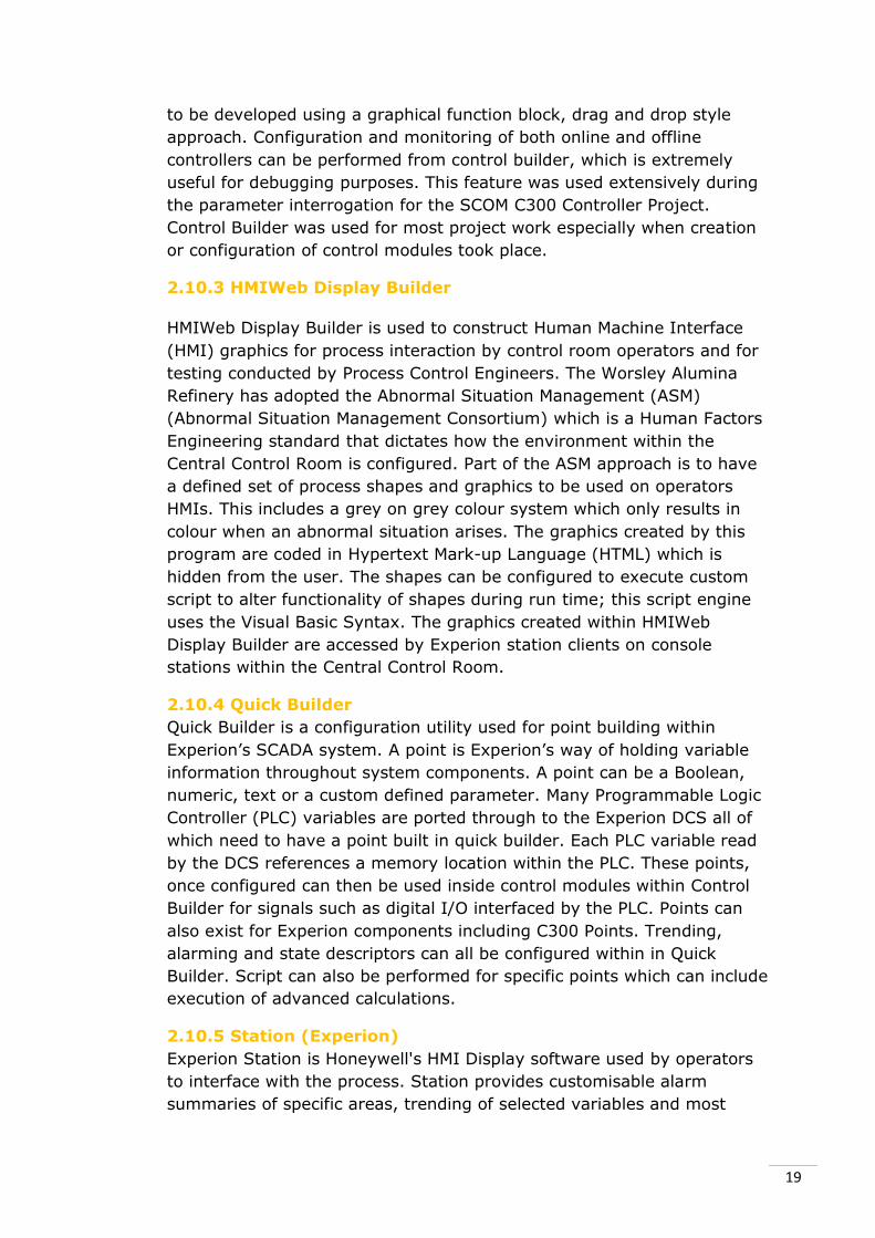
Figure 9 - Post E&G Bauxite Shuttles (Bin 3) ....................................................... 34
Figure 10 - Post E&G Bauxite Shuttles Transition ............................................... 35
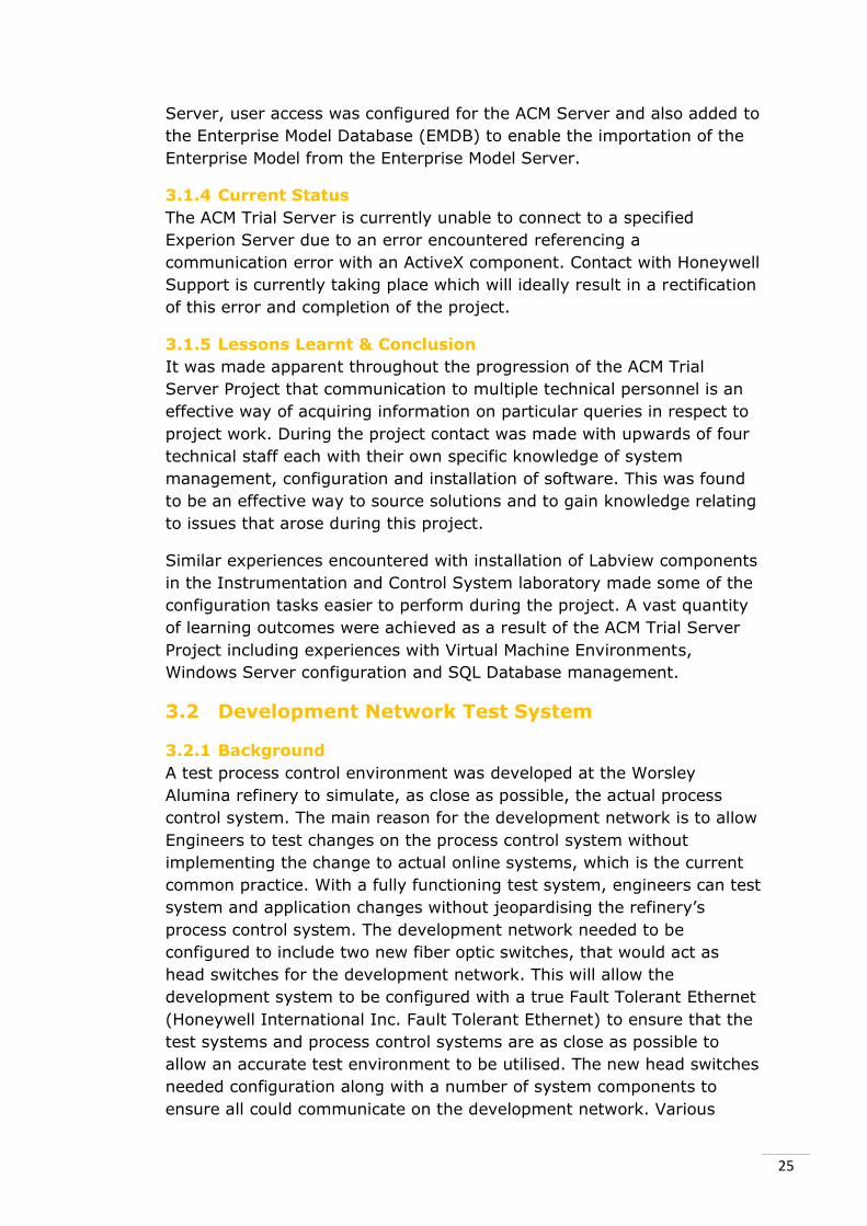
Figure 11 - Post E&G Bauxite Shuttles (Bin 5) ..................................................... 35
Figure 12 - Pre E&G Travel Drive Communication Architecture .................... 37
Figure 13 - Post E&G Travel Drive Communication Architecture .................. 37
Figure 14 - Modbus Scanner Installation ................................................................ 39
Figure 15 - Valve Stroke System Control Module Faceplate .......................... 41
Figure 16 - Valve Stroking Profile Output .............................................................. 42
List of Tables Table 1 - Internship Project Summary ...................................................................... 6
Table 2 - SCOM Parameter List ................................................................................... 30
5
1 Introduction For the past 6 years a select number of Murdoch Students studying Industrial Computer Systems Engineering and Instrumentation and
Control Systems Engineering are given the opportunity to complete a 16
week internship at the Worsley Alumina Refinery. This helps fulfil the
requirement of 500 hours of engineering practicum as per Engineers Australia’s requirement. The internship also provides students with the
opportunity to take what they have learnt in the previous three years at
university and apply it to “real world” situations and to build on their practical engineering knowledge. This provides great benefit throughout
the initial period of their engineering career.
The Worsley Alumina Refinery has a variety of control systems for
monitoring and controlling the refinery’s process. The central system is the Experion’s Process Knowledge System which is recognized as one of
the world’s most advanced process control systems. Because the refinery
runs continuously, it has essentially never been taken offline. It is for this
reason that upgrades to the system are carried out online. This practice has resulted in a diverse range of system components existing within the
refinery’s process control system. These range from legacy components
from former years to modern technologies. Since the refinery was commissioned in 1984 it has utilised Honeywell brand control systems.
With the diverse range of technology utilised at the Worsley Refinery, it
allowed for varying knowledge to be gained throughout the duration of
the internship.
During the internship a number of projects were assigned to the intern to
undertake. These projects related strongly to the engineering degree
majors, Industrial Computer Systems Engineering and Instrumentation
and Control Systems Engineering currently being completed. This allowed for a methodical approach when completing the projects to be developed
based on prior knowledge obtained from university studies. The projects
assigned coincided strongly with the engineering program offered at Murdoch University, this made the familiarisation period of assigned
projects a lot more efficient. As a part of university requirements, a
Project Plan and Project Progress Report were developed to communicate
with Academic Supervisor, Dr Gareth Lee the background, preliminary
scope and progress on the assigned projects.
During the placement the intern worked as a member of the process
control team which consists of a range of knowledgeable and friendly
professionals who develop and maintain the Refinery’s Control System.
This provided a great opportunity not only to query technical information
but to develop communication skills within a professional environment.
As a member of the process control team the intern was expected to attend and participate in Key Performance Indicator (KPI), Safety and
regular morning meetings all of which were a valuable learning
experience.
This thesis report aims to provide an in-depth account of the project
work completed during the internship period at the Worsley Alumina
6
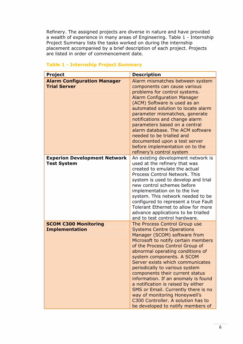
Refinery. The assigned projects are diverse in nature and have provided
a wealth of experience in many areas of Engineering. Table 1 - Internship
Project Summary lists the tasks worked on during the internship placement accompanied by a brief description of each project. Projects
are listed in order of commencement date.
Table 1 - Internship Project Summary
Project Description
Alarm Configuration Manager
Trial Server
Alarm mismatches between system
components can cause various
problems for control systems. Alarm Configuration Manager
(ACM) Software is used as an
automated solution to locate alarm
parameter mismatches, generate notifications and change alarm
parameters based on a central
alarm database. The ACM software needed to be trialled and
documented upon a test server
before implementation on to the
refinery’s control system
Experion Development Network
Test System
An existing development network is
used at the refinery that was
created to emulate the actual Process Control Network. This
system is used to develop and trial
new control schemes before implementation on to the live
system. This network needed to be
configured to represent a true Fault
Tolerant Ethernet to allow for more advance applications to be trialled
and to test control hardware.
SCOM C300 Monitoring Implementation
The Process Control Group use
Systems Centre Operations
Manager (SCOM) software from
Microsoft to notify certain members of the Process Control Group of
abnormal operating conditions of
system components. A SCOM Server exists which communicates
periodically to various system
components their current status
information. If an anomaly is found
a notification is raised by either SMS or Email. Currently there is no
way of monitoring Honeywell’s
C300 Controller. A solution has to be developed to notify members of
7
the group when a C300 encounters
a fault to allow it to be corrected in
a timely manner.
Facility 24B E&G Commissioning
As a part of the current refinery
expansion the bauxite bin shuttle
system is being overhauled to cater
for a fourth bin. This new
equipment had to be commissioned
before hand over to operators. Migration from PLC to the new
C300 controllers required new
control code to be developed by the
vendor. This code had to be Factory
Acceptance Tested (FAT) off site
and then commissioned on site by
Worsley Alumina Process Control
Engineers.
Valve Stroking Coding Inactivity of control valves can lead
to increased scaling and premature valve failure. By manipulating
valves away from their normal
operating conditions periodically valve scale can be reduced, this is
known as valve stroking. Code did
exist to stroke various valves
throughout the refinery. The code
existed on an older control system
which cannot communicate to the
new Control Execution Environment
(CEE) environment implemented on
site. A solution to valve stroking
has been implemented within the
CEE.
The time allocated at the beginning of each project had to be revised
constantly throughout the internship. There were varied reasons for this
including unavailable equipment, construction delays, human resource
availability and scope adjustments as a result of an increased
understanding of the projects. This was a beneficial learning experience
and made time management a crucial aspect throughout the entirety of
the internship.

8
2 Background A refinery overview, refinery process description, area descriptions and a
process control system overview will be given to provide context to the
write ups for the aforementioned projects. Tools and applications will also
be described as knowledge of them is a prerequisite of the following
sections of the report. General knowledge of the refinery was required
prior to starting project work and was essential in understanding the
scope and circumstance for each of the assigned projects preceding their
launch. A thorough understanding had to be developed not only prior to
starting project work but before full participation in regular meetings
could take place.
2.1 Refinery Overview
The Worsley Alumina Refinery was constructed in 1984, 20 kilometres
northwest of Collie in Western Australia. The project is a joint venture
with 86% owned by BHP Billiton, 10% owned by Japan Alumina
Associates Pty Ltd and 4% owned Sojitz Alumina Pty Ltd. An aerial
picture of the refinery can be observed in Figure 1 - Aerial Refinery
Overview (BHP Billiton Pty Ltd.).
Figure 1 - Aerial Refinery Overview (BHP Billiton Pty Ltd.)
The refinery produces Alumina which is extracted from the bauxite
provided by the Boddington Bauxite Mine. The bauxite used is
transported from the mine by one of the world’s longest overland
conveyors. The refinery uses a modified Bayer Process to produce the
Alumina which once calcined, is transported to the Bunbury Port by rail.
This alumina is stored until it is loaded onto transport vessels and
shipped worldwide to customers. (BHP Billiton Pty Ltd.)

9
The refinery has undergone a number of upgrades since it was initially
commissioned with each upgrade providing an increased alumina
production rate.
Currently the refinery is going through an expansion project named
Efficiency & Growth (E&G). This expansion will see the refinery go from
producing 3.55 million tonnes per annum to 4.6 million tonnes per annum of calcined alumina. The construction of this expansion is
currently 70% completed with commissioning of some areas currently
taking place. The Process Control Group is heavily involved in the
commissioning duties. The details of the commissioning process and the
Process Control Group’s involvement will be discussed within the Facility 24B Commissioning Project. Much of the project work completed during
the internship was directly related to the E&G project.
(BHP Billiton Pty Ltd.)
2.2 The Refinery’s Process
The bauxite fed into the refinery is 30% alumina (mainly gibbsite) with
approximately 70% impurities consisting of quartz, sulphates, kaolinite,
reactive silica and iron oxides. To produce aluminium, alumina with
extremely low levels of iron and silica is required. The refinery uses The
Bayer Process which exploits the fact that alumina readily dissolves in
hot caustic solutions leaving behind the non-soluble materials. This
property makes it relatively easily to remove unwanted impurities from
the dissolved alumina solution using a clarification system. The alumina
is precipitated out of the green liquor (alumina enriched caustic) by
seeding which results in alumina hydrate crystal growth. The refinery
includes an additional step of removing the three chemically bonded
water molecules by heating the alumina crystals to temperatures in
excess of 900°c, this is known as calcination. (BHP Billiton Pty Ltd.)

10
The refinery is divided into 6 major areas that house key parts of the
process. These areas are Raw Materials, Area 1, Area 2, Area 3, Area 4
and the Powerhouse. These process areas can be observed in Figure 2 -
Area Refinery Overview (BHP Billiton Pty Ltd.)
Figure 2 - Area Refinery Overview (BHP Billiton Pty Ltd.)
Each of these areas is then divided into specific facilities, each with its
own particular functionality. Throughout the area outlines, functionality
of the fundamental facilities will be described in detail with the less
significant facilities being omitted.
2.3 Raw Materials Outline
The Raw Material area accounts for the bauxite and coal entering the
refinery. Many conveyors exist which are interfaced by the DCS. The Raw
Materials area is one of the most crucial areas in the refinery as it is
responsible for delivering bauxite into the process. The Raw Materials
area also looks after lime and caustic unloading and alumina train
loading.
2.3.1 Facility 420 Overland Conveyor
An overland conveyor is used to transport crushed bauxite from the
Boddington Bauxite Mine to the refinery. The conveyor is one of the
largest in the world spanning over 50 kilometres. The conveyor’s speed is
approximately 23km/h which equates to approximately 2700tonnes of
crude bauxite per hour. Over the course of one year the overland
conveyor will transport 12.7 million tonnes of bauxite to the refinery
which is deposited onto the bauxite stock piles of Facility 15 Bauxite
Reclaiming. The conveyor is powered by a number of electric motors
which are controlled by high power Variable Speed Drives (VSD).
11
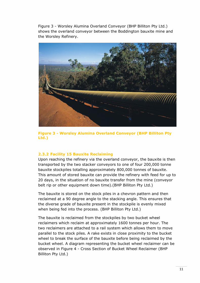
Figure 3 - Worsley Alumina Overland Conveyor (BHP Billiton Pty Ltd.)
shows the overland conveyor between the Boddington bauxite mine and
the Worsley Refinery.
Figure 3 - Worsley Alumina Overland Conveyor (BHP Billiton Pty Ltd.)
2.3.2 Facility 15 Bauxite Reclaiming
Upon reaching the refinery via the overland conveyor, the bauxite is then
transported by the two stacker conveyors to one of four 200,000 tonne
bauxite stockpiles totalling approximately 800,000 tonnes of bauxite.
This amount of stored bauxite can provide the refinery with feed for up to
20 days, in the situation of no bauxite transfer from the mine (conveyor
belt rip or other equipment down time).(BHP Billiton Pty Ltd.)
The bauxite is stored on the stock piles in a chevron pattern and then
reclaimed at a 90 degree angle to the stacking angle. This ensures that
the diverse grade of bauxite present in the stockpile is evenly mixed
when being fed into the process. (BHP Billiton Pty Ltd.)
The bauxite is reclaimed from the stockpiles by two bucket wheel
reclaimers which reclaim at approximately 1600 tonnes per hour. The
two reclaimers are attached to a rail system which allows them to move
parallel to the stock piles. A rake exists in close proximity to the bucket
wheel to break the surface of the bauxite before being reclaimed by the
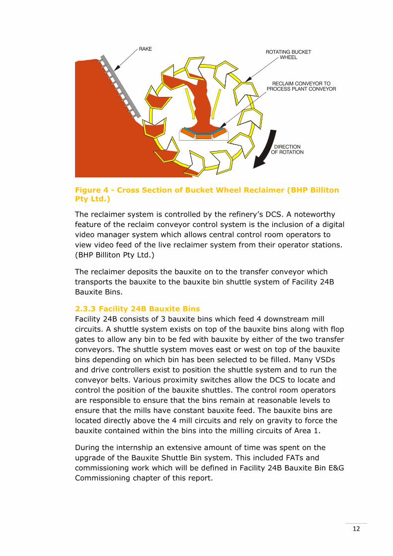
bucket wheel. A diagram representing the bucket wheel reclaimer can be
observed in Figure 4 - Cross Section of Bucket Wheel Reclaimer (BHP
Billiton Pty Ltd.)
12
Figure 4 - Cross Section of Bucket Wheel Reclaimer (BHP Billiton Pty Ltd.)
The reclaimer system is controlled by the refinery’s DCS. A noteworthy
feature of the reclaim conveyor control system is the inclusion of a digital
video manager system which allows central control room operators to
view video feed of the live reclaimer system from their operator stations.
(BHP Billiton Pty Ltd.)
The reclaimer deposits the bauxite on to the transfer conveyor which
transports the bauxite to the bauxite bin shuttle system of Facility 24B
Bauxite Bins.
2.3.3 Facility 24B Bauxite Bins
Facility 24B consists of 3 bauxite bins which feed 4 downstream mill
circuits. A shuttle system exists on top of the bauxite bins along with flop
gates to allow any bin to be fed with bauxite by either of the two transfer
conveyors. The shuttle system moves east or west on top of the bauxite
bins depending on which bin has been selected to be filled. Many VSDs
and drive controllers exist to position the shuttle system and to run the
conveyor belts. Various proximity switches allow the DCS to locate and
control the position of the bauxite shuttles. The control room operators
are responsible to ensure that the bins remain at reasonable levels to
ensure that the mills have constant bauxite feed. The bauxite bins are
located directly above the 4 mill circuits and rely on gravity to force the
bauxite contained within the bins into the milling circuits of Area 1.
During the internship an extensive amount of time was spent on the
upgrade of the Bauxite Shuttle Bin system. This included FATs and
commissioning work which will be defined in Facility 24B Bauxite Bin E&G
Commissioning chapter of this report.

13
2.3.4 Facility 11 Coal Unloading, Storage and Reclaiming
Coal is delivered to the refinery by rail and unloaded into the coal storage
pit. The coal is used to feed the Powerhouse which is responsible for
generating steam and power for the refinery. Facility 11 provides
approximately 2000 tonnes of coal a day to the powerhouse to ensure
enough utilities exist for the refinery’s process. (BHP Billiton Pty Ltd.)
The coal contained within the storage pit is reclaimed and conveyed to
the powerhouse for utility generation.
2.4 Area 1 Outline
2.4.1 Facility 24 Bauxite Grinding
Facility 24 consists of 4 mill circuits each comprising of: a rod mill; a ball
mill; dust collectors; DSM (Dutch State Mines) Screens and classifier feed
pumps. The normal operation of these circuits is that 3 are active and 1
is offline as a spare. Upwards of 450 tonnes per hour of bauxite is fed
through each of the mill circuits. The bauxite is mixed with spent liquor
to form slurry which is milled to achieve a size of 1.2mm or smaller. The
product of the mills is then fed in to the desilicators of Facility 26
Desilication. (BHP Billiton Pty Ltd.)
2.4.2 Facility 26 Desilication
After being reduced in size the bauxite slurry stream is fed into the
desilicator circuit which comprises of 5 desilicator tanks. The slurry is
heated for up to 9 hours in an effort to make the reactive silica convert
to desilication product. The reactive silica needs to be converted as it can
lead to increased scale build up in the downstream heat exchangers.
From the desilicators the product stream is transported to the digester
system. (BHP Billiton Pty Ltd.)
2.4.3 Facility 30 Digestion
Before entering the digestion vessels the product stream is transported
to the digestion feed tank where it is combined with a certain amount of
spent liquor in order to achieve a specified alumina to caustic ratio. From
the digestion feed tank the slurry is then passed through a number of
heat exchangers and flash vessels to heat the stream from 90°C to
175°C. After slurry passes through the numerous heat exchangers it is
fed into the digestion tanks. At this increased temperature and pressure
the alumina readily dissolves into the caustic. Nearly all of the alumina is
dissolved into the caustic with the remaining solids despatched back
through the flash vessels passing on heat to the incoming slurry stream.
(BHP Billiton Pty Ltd.)
2.5 Area 2 Outline
2.5.1 Facility 33 Clarification and Caustic
From the digestion tanks the slurry is transferred to the clarification

14
facility where the alumina rich liquor is separated from the bauxite
residue. The bauxite residue (mainly mud and sand) is allowed to settle
in the large settler tanks where it is then expelled in to the bauxite
residue disposal area. The overflow from this tank is the clarified alumina
enriched liquor which contains very fine particulate matter left over from
the bauxite residue. This solution is subsequently transferred to the
polishing filters in Facility 35. (BHP Billiton Pty Ltd.)
2.5.2 Facility 35 Polishing Filters
The fine particulate matter within the alumina enriched liquor stream is
removed by cloth filters before it is transported to area 3 for further
processing. This ensures minimal impurities are present during
precipitation. (BHP Billiton Pty Ltd.)
2.6 Area 3 Outline
2.6.1 Facility 41 Green Liquor Heat Interchange
The green liquor (alumina enriched) from area 2 is cooled by plate heat
exchangers from 103°C to 85°C. This heat is transferred to the spent
liquor stream which is heated from 60°C to 80°C and recycled to area 1
where it is used to create the slurry mixture. The cooled green liquor
stream is then transported to Facility 45 to begin precipitation of alumina
hydrate. (BHP Billiton Pty Ltd.)
2.6.2 Facility 45 Precipitation and Heat Interchange
The green liquor passes through 5 agitated tanks combined with clean
seed from Facility 46 in an effort to precipitate the alumina out of the
saturated green liquor stream. The presence of the clean alumina
hydrate seed acts as a nucleation point which draws the alumina out of
the green liquor. After most of the alumina has precipitated out of the
green liquor solution the alumina hydrate crystals settle to the bottom of
the last two agitator tanks and are harvested to obtain alumina hydrate
solid green liquor slurry. (BHP Billiton Pty Ltd.)
2.6.3 Facility 46 Seed Separation, Filtration and Hydrate
Classification
The main function of Facility 46 is to separate the heavier alumina
hydrate crystal particles from the finer particles. Product cyclones are
used with the lighter materials expelled out the top and the heavier
particles being deposited from the bottom. The fine particle streams are
then separated into fine and coarse seed, filtered and washed before
being charged back to the precipitators. The heavier particle stream is
transported to area 4 to commence calcination. (BHP Billiton Pty Ltd.)

15
2.7 Area 4 Outline
2.7.1 Facility 50 Filtration
The underflow of the product cyclones of Facility 46 are filtered to
remove the liquor from the slurry. A hydrate cake is formed at the top of
the first stage filters which is scraped from the top, mixed with wash
filtrate and then transported to the second stage filters. The hydrate is
washed with clean condensate to remove the remaining caustic soda and
other impurities. (BHP Billiton Pty Ltd.)
The washed alumina is transported to a venturi driven drier to commence
the first stage of calcination. The hydrate is subject to hot waste gas and
is driven towards the electrostatic precipitator (ESP). During travel the
chemically bonded water molecules are driven from the hydrate which is
heated to approximately 170°C by the waste gas. 80% of the alumina in
the gas stream is deposited by gravity into a chute before reaching the
ESP. The remaining 20% is captured by a high voltage negatively
charged grid of wires. The grids are regularly knocked, dislodging the
deposited alumina into chutes below, to be combined with the previously
obtained alumina. (BHP Billiton Pty Ltd.)
The alumina is then driven through the second stage where it is subject
to 900°C waste gases. Most of the water molecules are driven off during
this stage of calcination. The hydrate stream is then fed through a
cyclone to separate the hydrate and waste gases with the alumina
leaving the cyclone via the cyclone underflow. (BHP Billiton Pty Ltd.)
The underflow stream is fed into the calcincer furnace where it is mixed
with a natural burning gas mixture and a recirculating stream of fluidised
alumina. The fluidised alumina is forced from the top of the furnace by
convection and enters a recycle cyclone where the alumina is separated
from the hot gases. These hot gases are introduced into a second stage
venturi. The underflow of the recycle cyclone contains the fully
dehydrated alumina which is conveyed by secondary air to the storage
facility. During this transport much of the heat from the dehydrated
alumina is transferred to the conveying air which is then used by the
furnace for combustion with natural gas. (BHP Billiton Pty Ltd.)
2.7.2 Facility 51 Alumina Storage and Shipping
The alumina enters the storage silo after it has been cooled during
transport from Facility 50. The storage silo is capable of holding up to
100,000 tonnes of calcined alumina which equates a live capacity of
85,000 tonnes. Transportation from the storage silo is done by 24
pneumatically driven slides which are spaced throughout the bottom of
the silo to enable reclaiming from different sections. When reclaimed the

16
alumina is sent to the shipping silo which is used during rail load out.
(BHP Billiton Pty Ltd.)
Alumina is dropped into rail wagons beneath the shipping silo through 10
parallel chutes. Upon loading, the 10 chutes are lowered into the hatches
of the first two rail wagons. Along with the 5 chutes entering each
wagon, a flexible air duct also enters the wagon which vacuums the air
out allowing alumina hydrate to enter more evenly and also provides
alumina dust collection which is very important given the abrasive nature
of calcined alumina. The shipping silo has a 10,000 tonne capacity with
approximately 7,500 tonnes of live capacity. There are usually 6 trains
loaded each day with 36 wagons attached to each train. The loading
sequence is partially controlled by the DCS with input from the control
room operator also taking place. (BHP Billiton Pty Ltd.)
2.7.3 Facility 44 Liquor Burner
The main function of the liquor burner is to clean spent liquor of Total
Organic Carbons (TOC) and Sulphates. Once these two impurities are
removed the remaining sodium aluminate is recycled back to Area 1.
(BHP Billiton Pty Ltd.)
2.8 Powerhouse Outline
2.8.1 Powerhouse
The refinery’s steam and primary power source is the powerhouse which
is used for most of the unit operations required on site. The powerhouse
contains 3 coal fired boilers combining to produce 207 t/hr of 10MPa,
515°C steam. The steam is transported to one of three Mitsubishi Double
Extraction, Condensing Turbines and one Siemens Back Pressure
Turbine. These turbines are capable of producing 34 mega watts at 11.5
kV. The coal used by the powerhouse is transported from the coal
stockpile pit via a transfer conveyor system. (BHP Billiton Pty Ltd.)
2.8.2 Co-Generation Plant
An externally owned Co-Generation Plant exists in close proximity to the
Powerhouse. This facility utilises natural gas to produce supplemental
steam for the refinery and power for separate customers.
(BHP Billiton Pty Ltd.)
2.9 Control Systems Overview
The refinery’s control systems are a complex combination of legacy and
new equipment most of which is manufactured by Honeywell. The
continuous and intricate nature of the refinery’s process only allows for
parts of the control system to be offline for short amounts of time before
damage is done to the live process or process equipment (tank product
solidification etc.). Special actions and change management procedures
must be adhered to when installing new control system components onto
17
the network. This makes a complete control system overhaul almost
impossible.
The refinery has always preferred Honeywell Control Systems as their
preferred control system equipment vendor. Much of the Honeywell
equipment is catered towards process control orientated applications
therefore this is an obvious choice of control system manufacturer for the
refinery. Honeywell control equipment is recognised by industry as one of
the most advance Distributed Control Systems in the world. Worsley
Alumina has an excellent relationship with Honeywell International
including development work which will later be described in the C300
SCOM Monitoring Project section.
As Honeywell DCS upgrades have been rolled out to the refinery
throughout the last 30 years, parts of existing Honeywell control
infrastructure have been left behind. This has allowed for the connection
between the refinery’s different control system components to be
accomplished relatively easy and the combination of different
communication interfaces achievable.
The refinery was first commissioned with TDC2000 (Honeywell
International Inc. TDC2000) which was the current Honeywell Control
System at the time of implementation and was one of the first
Distributed Control Systems available to industry. The TDC2000 system
comprises of 2 main nodes, which are a Basic Controller and a Process
Interface Unit. These nodes could be loaded with process control
algorithms which could execute based on the analog inputs read by I/O
cards present on the controller. The nodes communicated between each
other via a Data Hiway connection (Honeywell International Inc. Data
Hiway) which had a maximum transfer rate of 256kb/s. This was
considered fast at the time of implementation. The TDC2000 was
upgraded to TDC3000 (Honeywell International Inc. TD3000) which
included the addition of the Local Control Network (LCN) (Honeywell
International Inc. Local Control Network) which coexisted with the Data
Hiway network. The LCN uses two coaxial cables for communication, one
primary and one secondary. This allows for redundancy to be achieved
and eliminates a single point of failure within the network similar to Fault
Tolerant Ethernet.
The first major upgrade to the refinery’s control systems was from
TDC3000 (the follow up to TDC2000) to the Total Plant Solution (TPS)
which was Honeywell’s current offering at the time. One of the major
additions during the upgrade was the Process Control Network. The
Process Control Network is built on an Ethernet connection which allows
for a much more diverse range of products to be incorporated and higher
transfer rates to be achieved (100Mb/s). New High Performance Manager

18
(HPM) and Advance Performance Manager (APM) Controllers were
introduced taking the place of some of the older Basic Controllers and
Process Interface Units. The Plant Historian Database (PHD) was also
implemented as the new Historian server with the TPS upgrade.
The most recent upgrade to the Refinery’s control system was from TPS
to Experion Process Knowledge System (EPKS). This upgrade includes
the installation of a number of Fault Tolerant Ethernet Networks
(Honeywell International Inc. Fault Tolerant Ethernet) throughout the
refinery. This upgrade also involves a number of new controllers to
replace various legacy controllers still present. Many of the more advance
control strategies have been implemented on Advance Control
Environment (ACE) Nodes.
The new controllers being implemented are Honeywell’s C300 controller
(Honeywell International Inc. C300 Controller) which executes the CEE.
The C300 Controller is considered to be one of the most advanced
industrial controllers on the market.
Numerous Schneider Quantum PLCs (Schneider Electric. Quantum
Programmable Logic Controller) also exist throughout the refinery, many
of which are being migrated to C300s as a part of the E&G Upgrade.
2.10 Tools and Applications Review
A number of different tools and applications were used during the course
of the internship. A summary of the main applications used during
engineering project work will be given. This will allow a better
understanding of work described in following sections of the reports to be
developed. Most of the applications listed are used by Process Control
Engineers on a daily basis at the refinery.
2.10.1 Configuration Studio
This program is used to perform most configuration tasks with regards to
EPKS DCS components. Many configuration tasks can be executed from
the Configuration Studio interface including user access permission
configuration, trend configuration, history archiving and various other
EPKS settings. Other EPKS applications such as Control Builder and
HMIWeb Display Builder are launched from Configuration Studio
2.10.2 Control Builder
Control Builder is a Honeywell application used on a daily basis by
Process Control Engineers to configure and monitor process control
strategies. Control Builder gives a graphical representation of the Control
Execution Environment (CEE) housed in various Honeywell controllers
including C200s, C300s and ACEs. This software allows control modules
19
to be developed using a graphical function block, drag and drop style
approach. Configuration and monitoring of both online and offline
controllers can be performed from control builder, which is extremely
useful for debugging purposes. This feature was used extensively during
the parameter interrogation for the SCOM C300 Controller Project.
Control Builder was used for most project work especially when creation
or configuration of control modules took place.
2.10.3 HMIWeb Display Builder
HMIWeb Display Builder is used to construct Human Machine Interface
(HMI) graphics for process interaction by control room operators and for
testing conducted by Process Control Engineers. The Worsley Alumina
Refinery has adopted the Abnormal Situation Management (ASM)
(Abnormal Situation Management Consortium) which is a Human Factors
Engineering standard that dictates how the environment within the
Central Control Room is configured. Part of the ASM approach is to have
a defined set of process shapes and graphics to be used on operators
HMIs. This includes a grey on grey colour system which only results in
colour when an abnormal situation arises. The graphics created by this
program are coded in Hypertext Mark-up Language (HTML) which is
hidden from the user. The shapes can be configured to execute custom
script to alter functionality of shapes during run time; this script engine
uses the Visual Basic Syntax. The graphics created within HMIWeb
Display Builder are accessed by Experion station clients on console
stations within the Central Control Room.
2.10.4 Quick Builder
Quick Builder is a configuration utility used for point building within
Experion’s SCADA system. A point is Experion’s way of holding variable
information throughout system components. A point can be a Boolean,
numeric, text or a custom defined parameter. Many Programmable Logic
Controller (PLC) variables are ported through to the Experion DCS all of
which need to have a point built in quick builder. Each PLC variable read
by the DCS references a memory location within the PLC. These points,
once configured can then be used inside control modules within Control
Builder for signals such as digital I/O interfaced by the PLC. Points can
also exist for Experion components including C300 Points. Trending,
alarming and state descriptors can all be configured within in Quick
Builder. Script can also be performed for specific points which can include
execution of advanced calculations.
2.10.5 Station (Experion)
Experion Station is Honeywell's HMI Display software used by operators
to interface with the process. Station provides customisable alarm
summaries of specific areas, trending of selected variables and most

20
importantly, control of the process via process graphics. As alluded to
previously, graphics displayed on station are configured within HMIWeb
Display Builder by Process Control Engineers.
2.10.6 Station (PlantScape)
An older version of station exists on all of the workstation PCs on site.
This version interfaces with the PlantScape (Experion R201 SCADA)
server which is a view-only system configured by the Process Control
Group. This allows employees other than operators to view live process
information and configure trends as they see fit. From PlantScape,
historical data can be copied and used in report making, which is
common practice for many Senior Managers, Production Engineers and
Process Engineers.
2.10.7 Microsoft Terminal Services Client (Remote Desktop)
Microsoft’s Terminal Services Client (MSTSC) is used to remotely access
Windows machines over the Process Control Network. This program is
used extensively during most engineering tasks performed on
engineering consoles and control system servers. The main benefit of
using this application is that access to a targeted machine can be
accomplished via the engineer’s workstation computer located at their
desk. Some virtual machines that exist on control system do not have
peripherals such as monitors, keyboards and mice plugged in therefore
MSTSC is the only way to access such machines. A Terminal Services
Server exists on the Process Control Network which acts as a gateway
between the site’s corporate network and the Process Control Network.
This server can also be used to remotely login from home if tasked with
weekend duty. Stringent security present on the Terminal Services
Server prevents unauthorised access to the Process Control Network
through this interface.
2.10.8 VMware VSphere Client
VMware VSphere client is an application which allows configuration of
Virtual Machine Servers remotely over Ethernet. VSphere can also be
used to remotely access a virtual machine’s desktop in similar fashion to
MSTSC. The VSphere remote access can be used without Windows
services being loaded compared to MSTSC which requires background
services to be running in order to function. This feature allows operating
system installations to be completed remotely. A noteworthy feature of
this software is physical drive emulation over a network interface which
will be discussed in more detail during the ACM Trial Server Project
description.

21
3 Intern Projects As mentioned in previous sections of this report, during the entirety of
the internship many projects were assigned to the intern. These projects
were not only substantial in size but were also diverse in terms of
learning outcomes. This provided an excellent opportunity to apply
theoretical knowledge developed at university to practical engineering
scenarios at the refinery. The next section of this report will cover in
detail the various projects including a background of each project,
required research, methodology used during work carried out and
concluding remarks including any lessons learnt during the project work.
3.1 ACM Trial Server
3.1.1 Background
As a part of the continual improvement of the refinery’s Process Control
System it had been proposed that a software package from Honeywell
known as Alarm Configuration Manager be trialled and assessed on a
virtual machine. ACM is used to compare the alarm settings to the
settings on the live control system. This ensures that mismatches
between control system components do not exist. ACM can be made to
run an alarm comparison manually or can be scheduled to run at
specified intervals. The results from this can be recorded and viewed or
can be made to enforce the change of inconsistent alarms to match the
MAD (Master Alarm Database). This functionality is performed by the
Enforcer Server which can be hosted on the ACM Server. The intern was
tasked with implementing an ACM Trial Server in order to comprehend
the feasibility of implementing such software to the Process Control
Network. This included installation, configuration and documentation of
the ACM software. Upon completion, recommendations could be made to
decide whether the ACM software could be used as an alarm analysis tool
on the Process Control Network at Worsley.
3.1.2 Required Research
Alarm Configuration Manager is a Honeywell Process Solutions software
package that can be configured to monitor alarm parameters across
multiple control systems components. It can then compare these
parameters in order to generate notifications for mismatches. It can
communicate with an Enforcer Server (also part of the ACM package) to
make alarm changes to match a specified system component.
VMWare ESXi (VMWare Esxi) is an operating system used to host virtual
machine guests. It allows the resources of a physical machine to be
divided up between a number of virtual machines in order to save on
hardware costs and physical space constraints. This approach has been
adopted by the Worsley Alumina Refinery with many of their control

22
system servers existing as guests hosted on VMWare ESXi Server
Installations. Figure 5 - VMware Architecture Visual Representation
shows a Visual Representation of the VMware architecture used on site.
Figure 5 - VMware Architecture Visual Representation
3.1.3 Method
In commencing the project a conversation with Process Control
Consultant, Rob Duggan took place to discuss an overview of the ACM
software and current status of the installation. During this discussion,
physical media was supplied which contained the ACM Software Package,
along with the EPKS Supplemental Software required to complete the
installation. Also on the installation media is documentation including an
installation guide, user guide and software guide for the ACM software
which were studied prior to installation tasks.
The ACM trial server has been created on a virtual machine which is
hosted as a guest on a VMware ESXi 4.1 installation. This machine is
housed in a virtual environment which provides the ability to snap shot
the current machine settings. This allows for system roll backs which aids
in problematic software installations. This assists with installations that
are extremely fragile in terms of configuration and helps immensely
when a rebuild of the machine is required. The time consuming
installation and configuration of a Windows Server Operating Systems
can be avoided with the use of regular system snap shots.
The first stage of the project was to complete installation of ACM which
had been partially installed on the virtual machine. A difficulty faced
during this stage of the project was the requirement of physical
installation media being read from an optical drive (DVD-ROM Drive) of
the server. This is challenging as the Windows 2003 installation present
on the virtual machine does not have a physical optical disk drive
installed, relying on network communications for file transfer and

23
installation of software. The primary style of interface to the server is
using MSTSC which does not support optical disk emulation over an
Ethernet Interface. A solution to this issue is to use VMware’s VSphere
Client software (VMWare VSphere) which allows an interface with the
VMware ESXi Server from a remote desktop connected to the same
network. Although VSphere can be used to remotely manage and
configure the ESXi Server it can also be used to provide a gateway into
guest machines in a very similar fashion to MSTSC. A major difference
between the VSphere and MSTSC is the ability to emulate physical drives
and communications ports over the Ethernet Connection. VSphere has
functionality which allows the local PC’s optical drive to emulate the
optical disk drive on the virtual machine over an Ethernet connection to
the ESXi Host Server. This functionality allows the use of installation
media remotely and hence finalization of the incomplete installation of
the ACM Server software was completed.
VSphere Administration access to the machine in question had to be
configured by a System Administrator which can be accessed through the
management interface on the VSphere Client software. This had to be
done using a user login which has administrative privileges across all
guest machines and on the ESXi Server system.
Installation tasks carried out on the ACM Trial Server Include installation
and configuration of an SQL (Structured Query Language) server on the
ACM machine; this is used to host the Master Boundary Database and
other system critical information. Care is required when configuring SQL
Databases on server installations especially with multiple user accounts
requiring permission to access specific databases. This problem was
encountered multiple times with user accounts automatically created
during Honeywell installations being denied access to databases required
by the ACM Server. Specific user permissions can be configured using the
Microsoft SQL Server Management Studio Program which provides an
efficient way to configure aspects of the databases being held on a
specified machine. Configuration of databases must be executed from a
Windows User Account with sufficient privileges to the database being
configured. The permissions can be managed by a global administrator.
Other tasks performed on the ACM Trial Server include configuration of
DCOM (Distributed Component Object Model) account security on the
Windows 2003 Server and configuration of local user accounts used by
the ACM software services and their associated permissions. This
required a particular procedure from the installation guide to be carried
out. The DCOM account settings allow a specific process to be executed
automatically by users with sufficient permissions. This allows the
Honeywell Server Services to be started automatically after the machine
has booted. These services are activated by the Honeywell Administrator

24
account automatically created during ACM installation. This account is
used for starting all the required Honeywell services for the server.
A required step for the ACM installations was to install the Experion
Application Framework (EAF) to allow communication to Experion Servers
contained within the refinery. This permits the ACM to view the
Enterprise Model which holds information about the assets configured for
EPKS. This allows ACM to generate tags for a given asset and eventually
be made to monitor these tags through the OPC gateway on Experion
servers. At this stage of the project a problem was encountered with the
installation of EAF. Experion Servers require a suffix after their machine
name which is a reference to their redundancy role. A “-A” had to be
appended to the computers name to allow the installation of EAF to
proceed. Initially it was thought that the only adverse effect this would
have on the machine was with the references to the machine’s name in
the SQL ACM database. To combat this, the necessary changes were
made to the SQL database with help from Systems Engineer, Andrew
Curtis. The SQL server logins were also made to comply with the name
change of the machine. A problem however with the ACM software
services arose which references the computers name in the ACM service
start-ups. This caused an error in the ACM software when trying to
configure ACM using the ACM Administration Client. After trying
numerous fixes the only work around was to complete a rebuild of the
server, including a fresh install of Windows 2003 Server Enterprise
Edition and the ACM Software. This was done in a similar fashion to the
ACM installation using VSphere to virtualise the Windows Installation Disc
but instead, mounting an .iso disk image from a network file share store
rather than using physical installation media on a local desktop.
During installation of Windows Server 2003 network settings had to be
configured. This included domain configuration that allows access to the
domain controller and therefore permits login through APAC accounts to
the Process Control Network. After this was complete the ACM installation
procedure was repeated with the new machine name which allowed the
EAF installation to proceed. Upon completion of this another problem
arose with the EAF installation. Configuration of EAF is done through
Honeywell’s Configuration Studio however this requires an Experion
“mngr” account login to configure user access for the first time. This
“mngr” account is also used to communicate to other Experion Servers
and therefore has to be consistent throughout the Experion Server
architecture. The “mngr” password on the ACM machine was not known
and therefore user access could not be granted onto the ACM Experion
Server through Configuration Studio. This meant that the ACM Experion
Server could not be configured. With help from Honeywell personnel this
problem was overcome by using a password change tool (PWDUTIL.EXE)
provided with the EPKS package. With security access to Experion
25
Server, user access was configured for the ACM Server and also added to
the Enterprise Model Database (EMDB) to enable the importation of the
Enterprise Model from the Enterprise Model Server.
3.1.4 Current Status
The ACM Trial Server is currently unable to connect to a specified
Experion Server due to an error encountered referencing a
communication error with an ActiveX component. Contact with Honeywell
Support is currently taking place which will ideally result in a rectification
of this error and completion of the project.
3.1.5 Lessons Learnt & Conclusion
It was made apparent throughout the progression of the ACM Trial
Server Project that communication to multiple technical personnel is an
effective way of acquiring information on particular queries in respect to
project work. During the project contact was made with upwards of four
technical staff each with their own specific knowledge of system
management, configuration and installation of software. This was found
to be an effective way to source solutions and to gain knowledge relating
to issues that arose during this project.
Similar experiences encountered with installation of Labview components
in the Instrumentation and Control System laboratory made some of the
configuration tasks easier to perform during the project. A vast quantity
of learning outcomes were achieved as a result of the ACM Trial Server
Project including experiences with Virtual Machine Environments,
Windows Server configuration and SQL Database management.
3.2 Development Network Test System
3.2.1 Background
A test process control environment was developed at the Worsley
Alumina refinery to simulate, as close as possible, the actual process
control system. The main reason for the development network is to allow
Engineers to test changes on the process control system without
implementing the change to actual online systems, which is the current
common practice. With a fully functioning test system, engineers can test
system and application changes without jeopardising the refinery’s
process control system. The development network needed to be
configured to include two new fiber optic switches, that would act as
head switches for the development network. This will allow the
development system to be configured with a true Fault Tolerant Ethernet
(Honeywell International Inc. Fault Tolerant Ethernet) to ensure that the
test systems and process control systems are as close as possible to
allow an accurate test environment to be utilised. The new head switches
needed configuration along with a number of system components to
ensure all could communicate on the development network. Various

26
other tasks were performed on the development network including
support tasks for Process Control Engineers with various problems using
the development system.
3.2.2 Required Research
SFP (Small Form-factor Pluggable Transceiver)
An SFP is a transceiver used for industrial communications between
network switches. SFPs are inserted into empty slots on industrial
switches which result in a physical connection to the switches
motherboard. These SFPs can then be used as a communication port to
interface other switches and computers similar to a normal network
switch. SFPs are available for copper Ethernet and fiber channel, this
allows many options in terms of switch port configuration to be utilised
which is one of their main benefits.
3.2.3 Method
To start the project a thorough review of the current system
configuration had to be completed. This included observing what physical
and virtual machines were present on the network and tracing any
network cables from switches to ensure they are connected to the correct
port. This was made easier by network architecture diagrams and switch
connection diagrams created for the development network. Current
versions of these diagrams edited by the intern can be observed in
Appendix C and Appendix D.
One of the initial tasks completed on the development network was to fix
the simulated C300 controllers hosted on the system. The controllers in
question are emulated on a dedicated simulation server housed on a
Windows 2003 Server implementation. The controllers had lost
communication with the Experion server, rendering the development
network unusable and the execution of the CEE impossible. After
reviewing the settings on the C300 simulation machine it was found that
the simulation host computer was configured with the wrong IP
addresses for both the controllers and the host computer. After a remote
desktop connection was made with the host server the machine IP
address was changed along with the C300 IP addresses. A restart of the
host machine was also completed to ensure that memory leaks were not
effecting the performance of the server. Changing the server’s and
C300’s IP address along with a restart of server solved the
communication issues allowing for control of the simulated C300s to be
accomplished.
Upon establishing communications to the Simulated C300 server a new
controller was built to test the functionality of the simulated
environment. This new simulated C300 was also used for control module

27
development for other projects, this did not affect other controllers
utilised by other Process Control Engineers on the development network.
An update of the network and switch configuration diagrams to represent
the current system was completed to convey accurate information to
systems personnel during discussions relating to the development
network. A meeting took place with systems personnel to discuss the
next steps in completing the network. A discussion detailing the
configuration exercise for the two new head switches made it apparent
that the currently unused head switches would be configured and a fiber
channel link would be established between the two equipment rooms
where the head switches are located. A member of the IT department
participated in the meetings and described how the existing connection
to the APAC (Asia Pacific) network would cease to exist and be replaced
by a connection into the Process Control Network through the Juniper
Core Network Switches. This would allow access to the development
system through the Process Control Network’s Terminal Services server
which is the same practice used by Process Control Engineers accessing
Engineering Consoles on the actual Process Control Network. This would
create a more accurate representation of the current Process Control
Network and is likely to lead to more use of development system for
application programming. Connection to the development network is
currently routed through the Information Management (IM) domain and
hence is on the “dirty” side of the network as opposed to the “clean”
Process Control Side.
Configuration of the head switches was performed using a serial link from
a Laptop PC to the physical port on the switch. This allowed the Cisco iOS
(Operating System on the Switch) to be remotely managed. From the
iOS, settings for each physical port could be configured including
machines names, allowable traffic, communication interface expected on
each specific port and general security settings including switch
administration passwords. This was completed on each switch.
The following step was to plug in and configure SFPs and to connect fiber
cables which were already pulled through to the required cabinets. When
trying to complete these connections it was discovered that the wrong
cable type had been pulled between the cabinets. The new head switches
make use of a new LC type connection for the fiber cable whereas the
Fiber Optic Breakout Terminal uses the older style SC Type Connection.
The cable that was installed between the required cabinets were SC to
SC type cables which meant connections could not be made between
switches. Upon learning this, the network switch diagrams were updated
to include cable type and cable length required to make the connection.
This was then used to create a list of cables required which was sent to a
vendor for quotation and ordering.

28
3.2.4 Current Status
The project is currently on hold as the new cables are required to
complete the fibre connections between switches. A plan is being
developed to carefully migrate the network to incorporate the new
switches that will lead to minimum downtime of the network. This will
ensure it can still be used during the upgrade and that a roll back
contingencies are in place to guarantee that the network can be
reconfigured to the old setting upon any errors that prevent the upgrade
moving forward.
3.2.5 Lessons Learnt & Conclusion
Documentation is a necessity when configuring networks that contain
multiple components such as switches and servers. At times during the
project confusion existed regarding connections between actual physical
ports and links detailed on network diagrams. From this project it is
apparent that up to date documentation can make configuration and
connections work a lot easier, as opposed to laboriously checking
physical connection and tracing communications over networks. As the
project carried on, more emphasis was placed on keeping relevant
documentation up to date and adding more information to these
documents in order to make configuration tasks easier to accomplish.
This lesson can be carried to other projects as well with change
management and thorough documentation playing a big role in most of
the project work carried out during the internship.
During this project the intern was exposed to switch configuration,
network management and infrastructure and support tasks all of which
were valuable experiences. The network architecture studied at
University proved to be vital knowledge when initially understanding the
architecture of the development network. The complexity of network
switches was underestimated when initially understanding the project as
experiences previously had only been with non-configurable Ethernet
switches and not with fiber channel switches that run their own operating
system.
3.3 SCOM C300 Monitoring
3.3.1 Background
The Worsley Alumina Process Control Department have implemented
Systems Centre Operations Manager (SCOM) software to monitor their
Process Control Servers. SCOM is used to monitor critical parameters
that can jeopardise the refinery’s control system, more specifically server
malfunctions. This allows technical staff responsible for the servers to
receive SMS and email notifications when systems are threatened while
personnel are present or away from the refinery (after hours). Currently
the Process Control Network has no way of automatically observing

29
status of controllers and their Peer Control Data Interface (PCDI) Links.
The current way of observing the status of controllers and their
associated PCDI links is to manually check them when performing a
change or maintenance on that specific controller using Experion’s
Control Builder.
The intern was tasked with finding a solution that will involve acquiring
data in SCOM from the controllers and PCDI Links in order to generate
notifications from SCOM in the event of a threatening situation. This
would alert the required engineer rather than waiting for an operator to
raise awareness of the malfunctioning controller.
3.3.2 Required Research
SCOM
Systems Centre Operation Manager is the monitoring software utilised by
the refinery to keep track of the health of process control system
components. SCOM is a Microsoft product which can be installed on a
Windows server operating system. Monitoring clients are installed on the
machines which require monitoring, the client scans up to date system
information and relays this back to a central SCOM server periodically.
The SCOM server can then raise notifications based on conditions
configured by systems personnel on the SCOM server; this can be
executed in a number of ways including SMS and Email notifications.
Companies that wish to support SCOM often provide management packs
which, once installed on the SCOM server, give extra functionality to
monitor their products. Custom script can also be utilised to monitor non-
standard components. The script used for this is written in Visual Basic.
3.3.3 Method
The first step taken was to research the SCOM software in order to gain
an understanding required to define the scope and required tasks. This
was done by holding discussions with Systems Engineer, Andrew Curtis
and Process Control Engineer, Ben Marler. Shortly after these
discussions, Andrew Curtis hosted a presentation where he gave an
insightful overview of SCOM including capabilities of the software.
It was clear from the discussions about the project that one of the first
tasks that would need to be completed was to produce an initial list of
parameters that would need to be monitored. This included filtering all
non-essential system parameters leaving a list of the most critical
monitoring parameters that will eventually be monitored by the SCOM
software. This was completed by using the monitoring functionality of
Control Builder to build a list of parameters available in the online
monitoring tab of the asset tree. After discussions with colleagues many
of the parameters could be disregarded as they were seen as insignificant
and not system critical. The OPC (OLE for Process Control) tags

30
generated by each C300 asset were also interrogated in order to find any
hidden parameters not available from the monitoring tab. This list was
extensive and much research had to be done in order to find the function
of each tag.
After completion of the refined list, a copy was sent to stake holders for
approval. This list was then relayed to Honeywell development personnel
for their input and possible advice in achieving the desired outcome. The
Final SCOM Parameter List can be found in Table 2 - SCOM Parameter
List
Table 2 - SCOM Parameter List
Descriptor Variable Point
State Information
Controller Status C300STATE
Redundancy Roll RDNROLESTATE
Synchronization State RDNSYNCSTATE
Battery State BATTERYNOTOK
Soft Failures Present SOFTFAIL
CPU Statistics
CPU Free (%) CPUFREEAVG
Minimum CPU Free (%) CPUFREEMIN
Time Since Power up UPTIME
Hardware Temperature
Current Temperature (degC) CTEMP
Peak FTE Traffic
LAN_A (Yellow) Failed LANAFAILED
LAN_B (Green) Failed LANBFAILED
InterLAN Comm Failed INTERLANFAILED
Crossover Cable Failed XOVERFAILED
Soft Failure
Battery State Warning BATTERYNOTOKSFTAB
Device Index Switches Changed BCDSWSTS
Factory Data Error FACTDATAERR
ROM Application Image
Checksum Failure
ROMAPPIMGCHKSMFAIL
ROM Boot Image Checksum Failure
ROMBOOTIMGCHKSMFAIL
WDT Hardware Failure WDTHWFAIL
WDT Refresh Warning WDTSWFAIL
Critical Task Watchdog Warning TASKHLTHMON
Uncorrectable Internal RAM
Sweep Error
RAMSWEEPERR
Correctable Internal RAM Sweep Error
RAMSCHRUBBERS
Uncorrectable User RAM Sweep
Error
BACKUPRAMSWEEPER
Corrected User RAM Sweep BACKUPRAMSCHRUBERRS

31
Error
IOLink(1) Soft Fail Error IOL1SOFTFAIL
IOLink(2) Soft Fail Error IOL2SOFTFAIL
Debug Flag Enabled DEBUGFLAGSET
Minimum HW Revision MINGWREVSF
Partner Not Visible on FTE PARTNERNOTVISFTE
Last Modified By: MODIFIEDBY
Date Last Modified By: VERSIONDATE
During the Honeywell User Group Demo a contact was made by Andrew
Curtis with a member of the Honeywell Development team who seemed
eager to provide assistance with the possible implementations of C300
monitoring through SCOM. Emails were exchanged which resulted in a
teleconference being scheduled. The teleconference consisted of
members from the Honeywell Development team and Worsley Alumina’s
Honeywell Account Manager along with Process Control Group members
from the refinery. All parties seemed eager to engineer a solution with
Worsley members communicating to Honeywell Developers the
capabilities of SCOM and the desired outcome of the project. Andrew
described to the Honeywell developers that a management pack could be
developed which would enable Honeywell’s customers to install an add-
on to their SCOM installation which would allow C300 Monitoring. All
parties agreed that a project with input from both parties would be the
best approach to move forward. The only problem was an intellectual
property issue from Honeywell’s side. Worsley Staff assured Honeywell
that any code developed would be Honeywell’s intellectual property and
that Worsley Alumina was only interested in the solution and not
developing a marketable product.
The customised SCOM script is written in Visual Basic to monitor non-
standard components within industrial networks. The process control
group have developed numerous custom scripts to monitor various
servers throughout the Process Control Network. With an example of
Visual Basic code used to poll C300 controllers various other specified
parameter communications will be developed.
3.3.4 Current Status
The project team currently have another teleconference to communicate
to Honeywell Engineers their progress. This has been scheduled in the
near future. An email was also received verifying that the Honeywell legal
department have agreed to sharing code with the Worsley Refinery
enabling the project to move forward during the scheduled
teleconference.

32
3.3.5 Lessons Learnt & Conclusion
The SCOM monitoring project has given an insight into the development
environment within a large corporation. Experience with communication
of project details across different companies has been a beneficial
learning exercise. Intellectual property is an issue that development
companies take very seriously which is understandable given the
competition between vendors to engineer practical solutions for their
customers. From the communications received, it is apparent that the
Worsley Alumina Refinery has no interest in the marketing or sale of a
C300 SCOM solution but instead are interested in optimising the
monitoring of control hardware on site only.
3.4 Facility 24B Bauxite Bin E&G Commissioning
3.4.1 Background
The E&G Expansion construction is being finalised in many areas of the
refinery. Commissioning of newly installed controllers along with new
code is required before handover to the refinery to ensure the process
control equipment is working correctly. Commissioning exercises during
the internship included the bauxite shuttles (Facility 24B). The bauxite
shuttles are used to feed 3 bins which provide 4 mill circuits with bauxite.
The E&G expansion will see a fourth bin be commissioned to feed a 5th
mill circuit. This upgrade also included migration of the current PLC
control to C300 control. During the stages of commissioning, code will be
migrated from Ladder Logic housed in Quantum PLCs to Control Code
housed in the new C300s. A number of stages have been defined for the
commissioning, the first of which started on the 22nd of September 2011
and saw partial migration of shuttle travel drive and shuttle conveyor
code. Factory Acceptance Testing had to be carried out for all code before
loading onto controllers on site. This includes testing all functionality of
the code to ensure that no errors exist during commissioning before
handover.
3.4.2 Required Research
Bauxite Bin System
The bauxite bin system contains 3 bins which feed the 4 downstream mill
circuits. Two rail systems exist above the bins which deposit crude
bauxite reclaimed from the stockpile yard into the bins via a sequence of
conveyors. Depending on the bin levels, the two shuttle systems can feed
any of the three bins. Proximity switches relay back to the control system
the position of the shuttle allowing for the control of the shuttle position.
The shuttle system can be run manually by operators or can be run
automatically. Automatic mode allows the control system to perform a
calculation which determines which bin should have top priority for
bauxite feed. This calculation takes into account, bin levels, milling rates

33
and various other parameters. Upon assigning priorities the control
system moves the shuttle to feed the top priority bin.
Figure 6 - Pre E&G Bauxite Shuttles (Bin 1), Figure 7 - Pre E&G Bauxite
Shuttles (Bin 2) and Figure 8 - Pre E&G Bauxite Shuttles (Bin3) show the
three possible positions of the shuttle system prior to the E&G upgrade.
Figure 6 - Pre E&G Bauxite Shuttles (Bin 1)
Figure 7 - Pre E&G Bauxite Shuttles (Bin 2)

34
Figure 8 - Pre E&G Bauxite Shuttles (Bin3)
After the E&G upgrade is complete a fourth bin will be used to feed a fifth
mill circuit. An extra shuttle conveyor will exist on each rail system to
provide feed to the fourth bin. This shuttle conveyor will make use of a
locking pin which will engage when the shuttles are in the correct
position. Upon engaging the lock pin, the shuttles will move as one to a
location where they can provide bauxite to bin 5. Figure 9 - Post E&G
Bauxite Shuttles (Bin 3), Figure 10 - Post E&G Bauxite Shuttles
Transition and Figure 11 - Post E&G Bauxite Shuttles (Bin 5) show the 3
steps to change bauxite feed from bin 3 to bin 5.
Figure 9 - Post E&G Bauxite Shuttles (Bin 3)
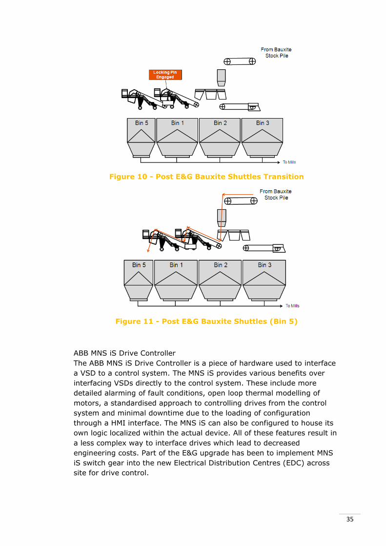
35
Figure 10 - Post E&G Bauxite Shuttles Transition
Figure 11 - Post E&G Bauxite Shuttles (Bin 5)
ABB MNS iS Drive Controller
The ABB MNS iS Drive Controller is a piece of hardware used to interface
a VSD to a control system. The MNS iS provides various benefits over
interfacing VSDs directly to the control system. These include more
detailed alarming of fault conditions, open loop thermal modelling of
motors, a standardised approach to controlling drives from the control
system and minimal downtime due to the loading of configuration
through a HMI interface. The MNS iS can also be configured to house its
own logic localized within the actual device. All of these features result in
a less complex way to interface drives which lead to decreased
engineering costs. Part of the E&G upgrade has been to implement MNS
iS switch gear into the new Electrical Distribution Centres (EDC) across
site for drive control.
36
3.4.3 Method
To initially understand the bauxite shuttle system along with the changes
being made to it, both the facility functional description (FFD) and the
control system functional description (CSFD) were studied meticulously.
The FFD provided a general overview of the bauxite shuttle process and
the process changes that were being made as a part of the E&G upgrade.
The CSFD went into more detail about the control system and the
expected functionality of control system during and after the completion
of the upgrade. These documents were created by Bechtel Corporation,
who is an Engineering, Procurement, Construction and Management
(EPCM) Company. Bechtel were tasked with completing the E&G Upgrade
by the Worsley Alumina Refinery.
Shortly after reading these documents Factory Acceptance Testing of
stages 3 and 4 of the bauxite shuttle upgrade was completed at the
Honeywell Facility in Burswood. These stages were mainly concerned
with code migration to C300 therefore the newly developed control
modules were the main focus of the FAT. The tests involved completing
the FAT procedure, developed by the responsible Honeywell Programmer
that they had developed from the CSFD. All interlocks, alarms and logic
were tested during the FAT procedure plus any additional tests that were
not covered in the FAT document.
One particular case that arose in the FAT was the loop speed at which the
control modules were running. The control modules had been set to run
at 500ms loop times as opposed to the site standard 1000ms loop time.
This discrepancy was noted as a potential threat to the functionality of
the code (specifically timing critical operations for shuttle movements
and under speed checking) and therefore prior tests were redone using
the site standard loop speed. Some timing functions had to be altered as
a result of the loop speed change. Another issue encountered during the
FAT procedure was a bug found in the code that resulted in the shuttle
moving in the wrong direction if a sequence start was initiated while
holding in a local directional hand switch. This could potentially result in a
trip of the bauxite shuttle system from an activated over travel limit
switch which is activated when the shuttle reaches its limits on the
shuttle rails. This bug was not picked up in a specific test but was found
when testing additional functionality of the code. Picking up bugs such as
these during the FAT procedure ensures minimal problems are
encountered during commissioning and ensures that the systems safety
is not compromised as a result of unproven code.
Before commissioning, a specialised test was conducted to ensure that
the travel drive responsible for powering the motor that moves the
shuttles was going to stop in time after receiving a stop signal from the
control system. This was a critical investigation to ensure that the shuttle

37
would not over shoot the specified bin when a bin change command was
initiated. For the check a test drive and motor were setup and connected
to the DCS to mimic the movements of the current travel drive. Because
the new travel drive was going to receive signals from the C300 a large
delay may have existed between the proximity switch activations read by
the PLC and the travel drive stop controlled by a C300. This was largely
due to the MNSIS Drive Controller adding an extra communication
pathway between the proximity switch and a drive stop. The comparisons
of the communication can be seen in Figure 12 - Pre E&G Travel Drive
Communication Architecture and Figure 13 - Post E&G Travel Drive
Communication Architecture.
Figure 12 - Pre E&G Travel Drive Communication Architecture
Figure 13 - Post E&G Travel Drive Communication Architecture
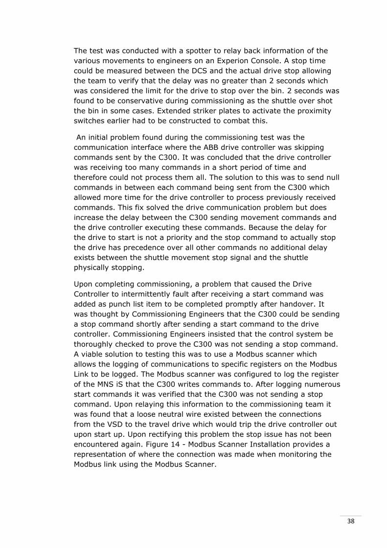
38
The test was conducted with a spotter to relay back information of the
various movements to engineers on an Experion Console. A stop time
could be measured between the DCS and the actual drive stop allowing
the team to verify that the delay was no greater than 2 seconds which
was considered the limit for the drive to stop over the bin. 2 seconds was
found to be conservative during commissioning as the shuttle over shot
the bin in some cases. Extended striker plates to activate the proximity
switches earlier had to be constructed to combat this.
An initial problem found during the commissioning test was the
communication interface where the ABB drive controller was skipping
commands sent by the C300. It was concluded that the drive controller
was receiving too many commands in a short period of time and
therefore could not process them all. The solution to this was to send null
commands in between each command being sent from the C300 which
allowed more time for the drive controller to process previously received
commands. This fix solved the drive communication problem but does
increase the delay between the C300 sending movement commands and
the drive controller executing these commands. Because the delay for
the drive to start is not a priority and the stop command to actually stop
the drive has precedence over all other commands no additional delay
exists between the shuttle movement stop signal and the shuttle
physically stopping.
Upon completing commissioning, a problem that caused the Drive
Controller to intermittently fault after receiving a start command was
added as punch list item to be completed promptly after handover. It
was thought by Commissioning Engineers that the C300 could be sending
a stop command shortly after sending a start command to the drive
controller. Commissioning Engineers insisted that the control system be
thoroughly checked to prove the C300 was not sending a stop command.
A viable solution to testing this was to use a Modbus scanner which
allows the logging of communications to specific registers on the Modbus
Link to be logged. The Modbus scanner was configured to log the register
of the MNS iS that the C300 writes commands to. After logging numerous
start commands it was verified that the C300 was not sending a stop
command. Upon relaying this information to the commissioning team it
was found that a loose neutral wire existed between the connections
from the VSD to the travel drive which would trip the drive controller out
upon start up. Upon rectifying this problem the stop issue has not been
encountered again. Figure 14 - Modbus Scanner Installation provides a
representation of where the connection was made when monitoring the
Modbus link using the Modbus Scanner.
39
Figure 14 - Modbus Scanner Installation
During the project numerous meetings relating to the commissioning
have been attended. Topics covered in the meetings include procedure,
hand over reporting, schedules and shutdowns.
3.4.4 Current Status
The first stage of the commissioning has been completed with all punch
listed items (items found to be non-critical and rectified outside of the
commissioning schedule) also completed. The second stage will
commence shortly which is identical to the first stage only on the
opposing shuttle system.
3.4.5 Lessons Learnt & Conclusion
The commissioning exercises completed during the internship were a
very rare opportunity to gain a vast range of hands-on engineering
exposure. Many of the problems encountered during the commissioning
required on-the-fly engineering solutions to be developed and
documented within a short period of time. Although pressure is placed on
engineers to commission as quickly as possible this pressure should not
compromise the tests to be completed as a part of commissioning. Safety
of the system is top priority which was made very apparent by Engineers
during the commissioning work.
3.5 Valve Stroking Control Module
3.5.1 Background
Control valves that are inactive for an extended period of time can suffer
from particulate matter build-up on their internal parts. This is known as
valve scale. Valve scale can lead to decreased performance and
premature valve failure. By exercising the valve away from its normal

40
operating level, scale build up can be minimised which result in reduced
maintenance cost. This is known as valve stroking.
Code had previously been developed by the Worsley Process Control
Team to periodically stroke control valves with the intention of
preventing scale build-up. This program was executed on HPM controllers
within an Application Module. Previous attempts to use this code with
CEE referenced points were unsuccessful. The intern was tasked with
engineering a viable solution for valve stroking within the CEE. The
control module developed includes configurable parameters to allow the
characteristics of the stroke to be manipulated. This will allow a common
module template to stroke many valves with only the configurable
parameters differing from valve to valve.
3.5.3 Method
The initial step taken to complete the Valve Stroking Project was to
gather background information on the required functionality of the
control module code. This was done by discussing with Process Control
Engineers the expected outcomes of the code. During these discussions it
was found the previous code was contained within a CAB. The refinery is
trying to minimise the use of CABs due to difficulty understanding and
debugging the Visual Basic code contained in them. The CAB however did
provide a good starting point for defining the functionality required for
the control module.
A simulated C300 on the development network was used during the
development of the control module. Initial development made use of a
RampSoak function block which is a standard Honeywell function block
within control builder. The RampSoak block allows numeric profiles to be
configured over a specific time period after receiving a start signal. It
was initially thought that this block could be used for the valve stroke
profile. After extensive coding it was found that this block was
inadequate for the required application as configuration of the profile
could only be done by accessing the control modules property form which
results in a more difficult configuration interface than is necessary. The
difficulty of storing the output level after commencing a stroking profile
was also difficult to implement when using the RampSoak block. This is
required as the control module needed to return the valve output level to
the output level prior to commencing a stroking profile.
Upon deciding that the RampSoak block was not the right block to use
for the stroking profile an alternative solution was trialled. This solution
was to use a combination of math function blocks to manipulate the
stroking signal dependant on how the function blocks were configured
from their face plates. After completion of this code a timed on-off signal
using a delay and pulse block in series was created. By configuring the

41
delay and pulse time respectively on these two blocks a period on-off
signal was generated. These timing parameters are used to configure the
hold time of each valve manipulation. On a rising edge (off to on) the
step size is either added or subtracted from the stroking signal
depending on a bit stored within a flag function block which is used as a
memory location for the count status (whether the count is going up or
down). Upon reaching a limit, the signal is capped at the specific level
which results in the count status flag being inverted. With the count
status now inverted the valve stroking continues opposing its previous
direction.
The code was developed and was placed into a System Control Module
which allows code to execute in similar fashion to a normal control
module with multiple function blocks but allows the control module to be
executed within a parent control module. This creates a “black box” type
scenario with the code encapsulated within a faceplate in Control Builder.
The configurable parameters can be altered on the faceplate which was
created to include the parameters likely to be changed as a part of
configuration. The Sequence Control Module developed can be found in
Figure 15 - Valve Stroke System Control Module Faceplate. This displays
the face plate with all configurable module parameters.
Figure 15 - Valve Stroke System Control Module Faceplate
When the valve stroking start signal is deactivated the stroking profile
will continue to manipulate the valve until the output level is within the
upper and lower stop band to avoid a large change of valve position
instantaneously. The upper and lower stop bands are configurable to
allow customisation of the module for the required valve. This
functionality prevents a hammering of the valve from taking place which
can lead to valve damage. An example of a stroking profile being output
from the Control Module can be observed in Figure 16 - Valve Stroking
Profile Output. The configurable parameters are also displayed. This

42
screenshot was taken using the Experion station client’s trending
functionality.
Figure 16 - Valve Stroking Profile Output
A screen shot of the control module code can be observed in Appendix B
of this report.
Throughout the coding of the control module numerous HMI graphics
were created for testing purposes using HMIWeb Display Builder. This
provided a convenient view and control of the control module from a
station client.
3.5.4 Current Status
The system control module code is complete with documentation being
finished before handover to the Process Control Group. Peer review and
testing are currently underway.
3.5.5 Lessons Learnt & Conclusion
The valve stroking project provided a large amount of exposure to
programming within Honeywell’s CEE. CEE knowledge and coding
experience had been developed at university prior to commencing the
internship and was extended during project work completed on the valve
stroking control module. The emphasis on efficient coding practice to
allow understanding of the code by other Engineers was a major focus
during the coding of the control module. This practice was also beneficial
when attempting to understand code which has not been altered or
viewed for an extended period of time; a common situation during the
control module development. Clean coding is greatly beneficial for
projects with large amounts of code and when a team environment is
involved in the development as is evident during university studies and
also throughout the course of the internship.

43
4 Additional Tasks Over the duration of the placement the intern was required to perform
additional tasks including various meeting and process control related
events. These additional activities are commonly performed by Process
Control Group members. This provided an excellent insight into the extra
activities Engineers are expected to fulfil on a week to week basis as
opposed to only being exposed to technical work which was the
expectation. The participation within these activities proved to be a
valuable learning experience with exposure to group discussions on
critical control system issues proving to be invaluable knowledge during
the course of the internship.
4.1 Process Control Meetings
The Process Control Group has regular meetings throughout the week.
These meetings allow Process Control Group members to communicate
any work that may be of interest to other members. Safety concerns are
also raised in these meetings along with any important announcements
that need to be made. Weekend duty is discussed with any outstanding
issues from the weekend being discussed on the Monday and any
potential threats communicated to the responsible engineer on Friday.
On Thursdays the group meets for a Key Performance Indicators (KPI)
meeting to assess personal performance of the previous week. Any
overdue items and outstanding issues are also discussed. The weekly
plant performance statistics are presented at KPI meetings.
4.2 Monthly Safety Meeting Chair
Every month the Process Control Group holds a meeting to discuss a
safety topic. A chair person is responsible for organising and presenting
material on a safety issue that they have chosen. Some of the topics that
have been experienced during the internship include ladder safety and
fire precautions within a hotel. These have been beneficial learning
exercises with a large amount of safety knowledge learnt as a result of
the topics discussed.
4.3 Honeywell Users Group Demo
The Process Control Group attended the Honeywell Users Group Demo
which gave the Worsley Process Control Group an opportunity to gain
knowledge of the new Honeywell hardware and software currently on
offer in development. A large amount of networking also takes place
which can provide great benefit when support is required for Honeywell
manufactured products at the refinery.

44
4.4 Engineering Open Day
The engineering departments at The Worsley Alumina Refinery in
association with Engineers Australia hosted an open day for South West
Australian year 12 students. The open day gave the students an
opportunity to understand the work that engineers are involved in and to
understand the life of both a student (University) and an Engineer in
industry. Students were given tours of the central control room and were
exposed to some of the equipment used on site. Many questions were
asked in regards to University work load which the intern was more than
happy to discuss.
4.5 Plant Support
During the placement the intern was involved in plant support activities
as they arose. This included fixing the development network when issues
were encountered, configuring area equipment rooms with fibre optic
keyboard, video, monitor (KVM) extenders and providing input into
technical discussions on coding challenges.

45
5 Internship Review BHP Billiton’s Worsley Alumina Refinery is one of the largest and most
efficient alumina refineries in the world. Part of the high efficiency can be
credited to the Process Control Group who maintains one of the most
advanced control systems in industry. The nature of the process only
allows for partial upgrades to the control system at any one time. This
requires a well thought out process including backup contingencies when
performing changes to the Process Control System. The conglomeration
of systems that the intern was exposed to was vast and a hugely
rewarding experience. Not until the intern worked at the refinery did he
realise the cross communication possible between legacy and new control
system hardware.
The internship has resulted in an immense number of learning outcomes
including commissioning knowledge, system and server administration,
technical development, project management, technical communication,
documentation techniques and code development. All the learning
outcomes that have been achieved are hugely beneficial experiences and
provide an on the job learning style when compared to university studies.
Throughout the internship many noteworthy experiences created
unexpected learning outcomes. This included the pressures of
commissioning which was completed for the bauxite shuttles. As a part of
the night shift commissioning team the exposure to on-the-fly
engineering of technical solutions provided a different style of
engineering to the typical practice completed during normal working
hours. Normally many Process Control Engineers are present within the
same room which is not the case during commissioning. More emphasis
is placed on engineering a solution in a timely manner which increases
pressure upon the Process Control Engineer.
Documentation was a key factor throughout the internship. Up to date
documentation can lead to increased efficiency when performing specific
engineering tasks. The reverse is also true with poor documentation
resulting in decreased work output. This was discovered early in the
internship and hence documentation was a focus for much of the project
work carried out.
Time management throughout the internship has been a key factor in
ensuring that the required tasks were completed within a timely manner.
With the parallel nature of the projects the intern’s schedule had to be
constantly revised to ensure that the most effective use of time was
being utilised. This is common practice within the Process Control Group
with many members relying on detailed schedules to divide up their time
between different tasks.

46
Not only has the internship been beneficial because of technical
knowledge gained but also experiences in communicating to technical
members of the refinery. This was a new experience as most
communications relating to control systems previously experienced
occurring among people with the same level of knowledge. Regular
meetings with the Process Control Group have created an understanding
of areas of the refinery not covered by project work and the general feel
for engineering tasks completed by other Process Control Engineers.
The internship has resulted in a vastly diverse range of learning
outcomes which is hugely rewarding in terms of career progression.

47
6 Conclusion As can be seen from the diverse range of projects that the intern is
involved with, the internship placement has proven to be a great
experience. Being part of a team-orientated environment has helped
immensely with any queries that arose during project work. The helpful
nature of the process control group members has resulted in a consistent
progression through the projects that were initially assigned.
The intern’s work load has slowly ramped up as the intern has become
more familiar with the process control system, the assigned projects and
the engineering practice used at Worsley. The intern views the placement
as a huge success and extremely beneficial due to the technical
knowledge gained through diverse range of technical tasks completed at
the Worsley Alumina Refinery.
The safety culture present at the refinery and in particular, exhibited by
the Process Control Group had not been observed before completing
work at the Worsley Alumina Refinery. The Process Control Group have
dedicated themselves to the safety of others and themselves in order to
reduce, as much as possible, the safety risks that they have control over.
This realisation has affected the intern’s outlook on safety not only at
work but in life outside of work.
All the experiences gained during the placement are credited to the
professionalism and willingness of the Process Control Team who helped
throughout the entirety of the placement. The intern was made to feel
like an active member from day one of the internship and has embraced
this opportunity with efforts to actively contribute to the Process Control
Group, both at meetings and when completing engineering work on
assigned projects.
The intern owes the Process Control Group a great amount of gratitude
for the opportunity to complete an internship at the BHP Billiton Worsley
Alumina Refinery.

48
7 References
Abnormal Situation Management Consortium.
http://www.asmconsortium.net/Pages/default.aspx
(accessed January 4, 2012).
An approach to HMI graphics used at the Worsley Alumina Refinery
Bechtel Corporation . Facility Functional Description for Process Facility
024 Bauxite Grinding. 13 October 2008.
This resource gave a functional overview of the bauxite grinding facility. This document
was read meticulously prior to any E&G work on Facility 024 to ensure that a thorough
understanding of the facility was achieved.
Bechtel Corporation. Control System Functional Description for Facility
15C/D Bauxite Reclaiming and Transfer. 23 March 2011.
This resource was studied to gain an understanding of the control system functionality of
Facility 15C/D. This document was also used during FAT procedures to ensure that the
tests completed were aligned with this document.
Bechtel Corporation. Control System Functional Description for Facility
24B Bauxite Grinding - Shuttle Conveyors. 22 July 2011.
This resource was studied extensively to gain an understanding of Facility 24B -Shuttle
Conveyors. This document was used during FATs for any queries that arose.
BHP Billiton Pty Ltd. “Full Bayer Manual.” Worsley DMS. n.d. (Internal)
/WAPL SHARE U/H - Human Resource Services/TD - Training and
Development/MD - Manual Development/Common/Full Bayer manual
(accessed August 15, 2011).
This document provided a thorough understanding of the Bayer Process used at the
Worsley Refinery. This document also contains descriptions of each facility which has
been of great benefit during the internship.
Honeywell International Inc. Alarm Configuration Manager Installation
and Setup Guide R310.1. Phoenix, 10 March 2008.
This document was used to perform the installation of the ACM software on the ACM Trial
Server. It provides detail and procedures for various installation and configurations of the
ACM software.
Honeywell International Inc. Alarm Configuration Manager System
Administration Guide R310.1. Phoenix, 6 March 2008.
This document provided information regarding the addition of control systems and tags
into the ACM system. The procedure contained within this document was used extensively
during the configuration of the ACM Trial Server.
Honeywell International Inc. Alarm Configuration Manager User Guide
R310.1. Phoenix, 10 March 2008.
This document describes the use of a complete ACM configuration from a user perspective
rather than an administrative perspective. This was document was used during the ACM
installation.
Honeywell International Inc. Configuration Studio (Software). 2007.
This program is used to perform most configuration tasks with regards to Experion

49
Servers. This program is used on a daily basis to configure servers that relate to the
intern projects. Additional Honeywell software is launched from Configuration Studio.
Honeywell International Inc. Control Builder (Software). 2007.
Control Builder is used to configure process control strategies that execute within the
Control Execution Environment housed in various Honeywell controllers. This software
was used program control modules for projects such as the Valve Stroking
Honeywell International Inc. C300 Controller.
http://hpsweb.honeywell.com/Cultures/en-
US/Products/Systems/ExperionPKS/ControlExecutionEnvironment/default
.htm (accessed January 4, 2012).
Honeywell controller used throughout the Refinery
Honeywell International Inc. Data Hiway.
http://hpsweb.honeywell.com/Cultures/en-
US/Services/SystemMigration/TDC2000DataHiway/default.htm
(accessed January 4, 2012).
Legacy Honeywell DCS communication protocol still in use at the Worsley Alumina
Refinery
Honeywell International Inc. Experion Application Framework
Configuration Guide R310.2. Phoenix, 28 March 2008.
This document describes the configuration of Experion Application Framework software
which is a requirement of an ACM Server.
Honeywell International Inc. Experion Station (Software). 2007.
Experion Station is Honeywell's HMI Display software used by Engineers to test process
graphics and by operators to interface with the process. This software was used
extensively during commissioning duties and during control module development.
Honeywell International Inc. Fault Tolerant Ethernet.
http://hpsweb.honeywell.com/Cultures/en-
US/Products/Systems/ExperionPKS/FaultTolerantEthernet/default.htm
(accessed January 4, 2012).
Honeywell Experion DCS communication protocol used at the Worsley Alumina Refinery
Honeywell International Inc. HMIWeb Display Builder (Software). 2010.
HMIWeb Display Builder is used to construct HMI graphics for testing purposes and for
operator interfacing. This software was used during the development of control modules
to allow convenient testing.
Honeywell International Inc. Local Control Network.
http://hpsweb.honeywell.com/Cultures/en-
US/Products/Systems/TDC3000/default.htm (accessed January 4, 2012).
Legacy Honeywell DCS communication protocol still in use at the Worsley Alumina
Refinery
Honeywell International Inc. TDC2000 (Software).
http://hpsweb.honeywell.com/Cultures/en-

50
US/Products/Systems/TDC2000/default.htm (accessed January 4, 2012).
Legacy Honeywell DCS still in use at the Worsley Alumina Refinery
Honeywell International Inc. TD3000 (Software).
http://hpsweb.honeywell.com/Cultures/en-
US/Products/Systems/TDC3000/default.htm (accessed January 4, 2012).
Legacy Honeywell DCS still in use at the Worsley Alumina Refinery
Schneider Electric. Quantum Programmable Logic Controller.
http://www2.schneider-electric.com/sites/corporate/en/products-
services/automation-control/products-offer/range-
presentation.page?c_filepath=/templatedata/Offer_Presentation/3_Range
_Datasheet/data/en/shared/automation_and_control/modicon_quantum.
xml (accessed January 4, 2012).
Programmable Logic Controller used throughout the Refinery
VMWare Esxi (Software).
http://www.vmware.com/products/vsphere-hypervisor/overview.html
(accessed January 4, 2012).
Virtual Machine Operating System used at the Worsley Alumina Refinery
VMWare VSphere (Software).
http://www.vmware.com/products/vsphere/mid-size-and-enterprise-
business/features.html (accessed January 4, 2012).
Virtual Machine Operating System remote management tool used at the Worsley Alumina
Refinery
Worsley Alumina Pty Ltd. Experion Training for Electrical/Instrument
Technicians. Collie, 29 July 2009.
This document provided an understanding of the Experion System. Contained within this
document are the Worsley specific standards used during coding and graphic
constructions.
Worsley Alumina Pty Ltd. Process Control Systems Overview. Collie, 4
May 2000.
This document details the refinery’s control system and the various hardware and
software present throughout the site.
Worsley Alumina Pty Ltd. Restarting Experion ESV-T Servers Work
Instruction. Collie, 13 February 2008.
This work instruction is used during the restart of Experion Servers. The intern uses this
procedure during restarts of Experion Servers including the Development Network.

51
8 Glossary
ACE Advance Control Environment
ACM Alarm Configuration Manager
APAC Asia Pacific
APM Advanced Process Manager
ASM Abnormal Situation Management
C300 Latest Honeywell Controller
CAB Calculated Algorithm Block
CEE Control Execution Environment
CSFD Control System Functional Description
DCOM Distributed Component Object Model
DCS Distributed Control System
DSM Screen Dutch State Mines Screen
E&G Efficiency & Growth Upgrade
EAF Experion Application Framework
EDC Electrical Distribution Centre
EMDB Enterprise Model Database
EPCM Engineering, Procurement, Construction and Management
EPKS Experion Process Knowledge System
ESP Electrostatic Precipitator
FAT Factory Acceptance Test
FFD Facility Functional Description
HMI Human Machine Interface
HPM High Performance Manager
iOS Cisco Switch Operating System
KPI Key Performance Indicator
LC Connector New type fiber optic connector(small)
LCN Local Control Network
MAD Master Alarm Database
MNS iS ABB Drive Interface Device
MSTSC Microsoft’s Terminal Services Client
OPC OLE for Process Control
PCDI Peer Control Data Interface
PLC Process Logic Controller
SC Connector Old type fiber optic connector(large)
SFP Small Form-factor Pluggable Transceiver
SQL Structured Query Language
VSD Variable Speed Drive
52
9 Appendices
9.1 Appendix A – Industry and Academic Endorsement
ENG450 Engineering Internship
Industry and Academic Supervisor
endorsement pro forma
This is to be signed by both the industry and academic supervisor and
attached to the final report submitted for the internship.
We are satisfied with the progress of this internship project and that the
attached report is an accurate reflection of the work undertaken.
Signed:
Industry Supervisor
Signed:
Academic Supervisor

53
9.2 Appendix B – Valve Stroking Control Module CEE
Code

54

9.3 Appendix C - Development Network Architecture
55

9.4 Appendix D - Development Network Switch Diagram
Created by Kyle Edwards,
Edited by Matthew Ray 56


![[Internship Report] folder... · Web view[Internship Report] [Internship Report] 3 [Internship Report] Prince Mohammed Bin Fahd University College of Computer Engineering and Science](https://static.fdocuments.us/doc/165x107/5adbc5e37f8b9add658e5f6e/internship-report-folderweb-viewinternship-report-internship-report-3-internship.jpg)

