Engineering Graphics Glossary - Department of …me.emu.edu.tr/vaziri/CAD GLOSSARY.pdf · acme...
72
Page 1 of 72 Engineering Graphics Glossary Indicates that the value is a diameter. 3D printing Lower-cost rapid prototyping process that "prints" layers of molten thermoplastic material. absolute coordinates The exact location of a specific point in terms of X, Y, and Z from the fixed point of origin. acme thread A thread form used to transmit power. addendum Radial distance from pitch circle to top of gear tooth. adjacent views Two orthographic views that share a common dimension and are located so that the dimension is aligned in both views. aesthetic constraints Design guidelines that express what is known about taste and appeal in a certain market. algorithm A computational procedure, as in the process used to solve a problem or render an image. aligned Describes dimension text that runs in the same direction as the dimension line. aligned section A section view where the cutting plane passes through angled arms, holes, or other features located around a central cylindrical shape and the section view is rotated into a single plane that shows features in the section true size. allen screw Special set screw or cap screw with hexagon socket in head. allowance The minimum clearance or maximum interference that is desired between two members when they are at maximum material condition. alloy Two or more metals in combination, usually a fine metal with a baser metal. aluminum A lightweight but relatively strong metal. Often alloyed with copper to increase hardness and strength.
Transcript of Engineering Graphics Glossary - Department of …me.emu.edu.tr/vaziri/CAD GLOSSARY.pdf · acme...

Page 1 of 72
Engineering Graphics Glossary
Indicates that the value is a diameter.
3D printing Lower-cost rapid prototyping process that "prints" layers of molten thermoplastic
material.
absolute coordinates The exact location of a specific point in terms of X, Y, and Z from the fixed point of
origin.
acme thread A thread form used to transmit power.
addendum Radial distance from pitch circle to top of gear tooth.
adjacent views Two orthographic views that share a common dimension and are located so that the
dimension is aligned in both views.
aesthetic constraints Design guidelines that express what is known about taste and appeal in a certain
market.
algorithm A computational procedure, as in the process used to solve a problem or render an
image.
aligned Describes dimension text that runs in the same direction as the dimension line.
aligned section A section view where the cutting plane passes through angled arms, holes, or other
features located around a central cylindrical shape and the section view is rotated into a
single plane that shows features in the section true size.
allen screw Special set screw or cap screw with hexagon socket in head.
allowance The minimum clearance or maximum interference that is desired between two members
when they are at maximum material condition.
alloy Two or more metals in combination, usually a fine metal with a baser metal.
aluminum A lightweight but relatively strong metal. Often alloyed with copper to increase
hardness and strength.

Page 2 of 72
ambient The overall amount of light that exists in the environment of a rendered scene.
ambient light Light that strikes all surfaces equally, similar to room lighting.
analytical model A model that captures the behavior of the system or device in a mathematical
expression or schematic drawing that can be used to predict future behavior.
angle The space between two lines (or planes) that diverge from a single point (or line).
angle iron A structural shape whose section is a right angle.
animation A sequence of still images that give the illusion of motion when viewed in rapid
succession.
anneal To heat and cool gradually, to reduce brittleness and increase ductility.
antialiasing A process that reduces the jagged edges in raster images by shading adjacent pixels.
apparent intersection An intersection in a 2D view that is not a true intersection in 3D space.
approximation An inexact result that is suitable for a given purpose.
arc-weld To weld by electric arc. The work is usually the positive terminal.
as per manufacturing process A note signifying that the typical tolerance for the specified manufacturing process is
acceptable for the part.
assembly drawing A drawing that shows how all the parts in an assembly fit together.
assembly mode The operating status of a CAD package that allows you to link multiple parts together
into assemblies.
associative Describing an entity that is linked to a second entity and will change when the second
one does.
associative dimensions Dimensions inserted as a group of drawing objects related to geometric entities in the
drawing. If the size of the geometric entity changes, the dimension values will update
accordingly.

Page 3 of 72
auxiliary view An orthographic view of an object using a direction of sight other than one of the six
basic views (front, top, right-side, rear, bottom, left-side); used to show a surface that is
not parallel to the true size of any of the principal viewing planes.
B-spline
A blended piece-wise polynomial curve passing near a set of control points.
babbitt A soft alloy for bearings, mostly of tin with small amounts of copper and antimony.
ball tag A circled number identifying each part shown in an assembly drawing; also called a
bubble number.
base feature The first feature created in a parametric model and one from which other features are
defined.
base point The point on a parametric sketch that remains fixed to the coordinate system when the
sketch is solved.
baseline dimensioning Locating a series of features from a common base feature.
basic angle An angular dimension stated as a basic dimension.
basic dimensions The theoretically exact, untoleranced dimensions that specify the perfect location, size,
shape, or angle of a feature.
basic hole system A tolerancing method that uses the lower limit or minimum size of the hole as the basic
size.
basic shaft system A tolerancing method that uses the upper limit or maximum size of the shaft as the
basic size.
basic size The theoretical size from which tolerance is assigned.
bearing A supporting member for a rotating shaft.
bend allowance An amount added to the inside dimensions of a sheet metal part to add material needed
to form the bend to the flat pattern for the part.
bevel An inclined edge, not at right angle to joining surface.

Page 4 of 72
Bezier curve A polynomial curve defined by a set of control points where the first and last control
points are on the curve. This was the first CAD method that used spline approximation
to create flowing curves.
bicubic surface A sculptured plane, mathematically describing a sculptured surface between 3D curves.
bidirectional associativity Describes the link between the drawing and the model in a parametric modeler. If a
change is made to the model, the drawing is automatically updated to reflect the
change; if a change is made to the parametric dimensions in the drawing, both the
drawing and the model update automatically.
bilateral tolerance Tolerance that specifies a base value for a dimension and the allowable range of
deviation from that dimension, both plus and minus.
bill of materials (BOM) A list of and information about the individual parts in an assembly.
block diagram A schematic drawing that shows the relationships in a system, using simple shapes for
the entities.
bolt circle A circular center line on a drawing, containing the centers of holes about a common
center.
BOM Bill of materials.
Boolean operation Finding the union (addition), difference (subtraction), or intersection (common area) of
two or more sets, such as the data defining a CAD solid.
bore To enlarge a hole with a boring mill.
boss A short protrusion beyond the normal surface of a part, often used to provide a strong
bearing surface.
bottom-up design A design process that starts at the part level, sizing individual components and building

Page 5 of 72
the design up from them.
boundary representation (BREP) An approach to creating a CAD database that stores the external boundaries of the
surfaces making up the 3D model.
bounding box The smallest cube that a solid will fit inside.
brainstorming A method for generating many ideas.
brass An alloy of copper and zinc.
braze To join with hard solder of brass or zinc.
BREP Boundary representation.
Brinell A method of testing hardness of metal.
broach A long cutting tool with a series of teeth that gradually increase in size which is forced
through a hole or over a surface to produce a desired shape.
bronze An alloy of eight or nine parts of copper and one part of tin.
buff To finish or polish on a buffing wheel composed of fabric with abrasive powders.
bump map Converts color intensity or grayscale information to heights to give the appearance that
features are raised above the surface, like embossed letters.
burnish To finish or polish by pressure upon a smooth rolling or sliding tool.
burr A jagged edge on metal resulting from punching or cutting.
bushing A replaceable lining or sleeve for a bearing.
buttress thread A thread form used to transmit power.
cabinet projection
An oblique projection in which the depth of the object is shown half size.
calipers

Page 6 of 72
An instrument with two hinged legs used to measure internal and external diameters.
cam A rotating member for changing circular motion to reciprocating motion.
carburize To heat a low-carbon steel to approximately 2000°F in contact with material which
adds carbon to the surface of the steel, and to cool slowly in preparation for heat
treatment.
Cartesian coordinate system A rectangular coordinate system created by three mutually perpendicular coordinate
axes, commonly labeled X, Y, and Z.
caseharden To harden the outer surface of a carburized steel by heating and then quenching.
castellate To form like a castle, as a castellated shaft or nut.
casting (n) A metal object produced by pouring molten metal into a mold.
casting (v) The process of pouring molten metal into a hollow mold to form a metal part
cast iron Iron melted and poured into molds.
CATIA A parametric modeling package from Dassault.
cavalier projection An oblique projection in which the depth of the object is shown full size.
cavity The side of the mold that forms the outside shape of the object.
center drill A special drill to produce bearing holes in the ends of a workpiece to be mounted
between centers. Also called a combined drill and countersink.
center line A linetype used to indicate the axis of symmetry for a part or feature, the symmetrical
alignment of a pattern of holes, and the path of motion for moving parts in an assembly.
centroid A point defining the geometric center of an object. The centroid and center of gravity
coincide when the part is made of a uniform material in a parallel gravity field.
chained (continued) dimensioning A dimensioning method that uses the last extension line of the previous dimension as
the beginning of the next.
chamfer

Page 7 of 72
A small angled surface formed between two surfaces.
chase To cut threads with an external cutting tool.
cheek The middle portion of a three-piece flask used in molding.
chill To harden the outer surface of cast iron by quick cooling, as in a metal mold.
chip To cut away metal with a cold chisel.
chord length The straight line distance between the start point and the endpoint of an arc.
chuck A clamp that holds a tool or piece of material, as in a lathe or drill.
circular runout A measure of the variation in the circular shape of an object as it is rotated about a
datum axis.
circular view A view of a cylinder in which it appears as a circle.
circumscribed Drawn around the outside of a base circle.
clearance fit A tolerance for mating parts in which the smallest external member is larger than the
largest internal member, resulting in a space between them.
CNC Computer numerical control.
coin To form a part in one stamping operation.
cold-rolled steel (CRS) Open hearth or Bessemer steel containing 0.12-0.20% carbon that has been rolled while
cold to produce a smooth, quite accurate stock.
colinear Lying on the same straight line.
Page 8 of 72
collar A round flange or ring fitted on a shaft to prevent sliding.
color depth The number of colors and bits used to define the color in an image.
colorharden Same as caseharden, except that it is done to a shallower depth, usually for appearance
only.
composite A material made up of two or more distinct substances.
compression spring A spring designed to be compressed and returned to its original shape.
computer numerical control (CNC) Using a computer to direct machine processes.
construction lines Thin lines that serve as guides while sketching or drawing.
constructive solid geometry (CSG) An approach to creating a CAD database that stores the solids and operations used to
create a 3D model.
contact inspection Evaluating the acceptability of a part by means of a measurement device such as a gage
or probe that touches the part or feature.
contour Outline of an object's shape.
Coons patch A bicubic surface patch interpolated between four edges.
coordinate dimensioning Used for parts that have complex interior hole patterns.
coordinate values Used to identify the location of a point, using the Cartesian coordinate system; X
represents the horizontal position on the X axis, and Y represents the vertical position
on the Y axis. In a three-dimensional drawing, Z represents the depth position on the Z
axis.
cope The upper portion of a flask used in molding.
core To form a hollow portion in a casting by using a dry-sand core or a green-sand core in a
mold.
core A shape that fits in a mold to form a hole in a molded part. Also, the side of the mold
that forms the interior features of the molded part.

Page 9 of 72
coreprint A projection on a pattern which forms an opening in the sand to hold the end of a core.
cosmetic dimensions Nonassociative dimensions that are added to a drawing view, not derived from the
model.
cotter pin A split pin used as a fastener, usually to prevent a nut from unscrewing.
counterbore (v) To enlarge an end of a hole cylindrically with a counterbore.
counterbore (n) A cylindrical recess around a hole, usually to receive a bolt head or nut.
countersink (v) To enlarge an end of a hole conically, usually with a countersink.
countersink A conical-shaped recess around a hole, often used to receive a tapered screw.
crest The top surface of a thread where the two sides join.
crown A raised contour, as on the surface of a pulley.
CSG Constructive solid geometry.
curve fitting Generating an equation that describes a set of empirical data.
cutting plane The plane that defines the cut through an object that reveals the surfaces shown in a
section view.
cutting plane line A linetype used to define the location on an object where a sectional view was taken.

Page 10 of 72
cyanide To surface-harden steel by heating in contact with a cyanide salt, followed by
quenching.
cylindrical coordinates The location of a point given as a radius, angle from the X axis, and distance along the
Z axis.
datum plane
A geometric reference point for parametric dimensions.
datum surface A theoretically exact geometric reference used to establish the tolerance zone for a
feature.
decision matrix A tool for systematically ranking alternatives according to a set of criteria.
dedendum Distance from pitch circle to bottom of tooth space.
default coordinate system The coordinate system used by a CAD modeling system to define and locate geometric
entities in the CAD database.
delimited Separated by a specified character, such as a space, comma, or tab.
delta angle The included angular value from the start point to the endpoint.
derived surfaces Surfaces created with mathematical methods that use the edges of the patches being
combined to create a smooth joint.
descriptive geometry Mathematical techniques used to accurately describe 3D geometry in 2D.
descriptive model A model that represents a system or device in either words or pictures.
design constraint A limit on the range of options that are acceptable.
design intent The purpose or function of a feature in a part or of a part in an assembly.
design rule A relationship that must be preserved or a constraint that must be met to achieve the
design intent.
detail drawing A part drawing.

Page 11 of 72
development A flat pattern for a 3D shape that may be folded into the shape.
diametral pitch Number of gear teeth per inch of pitch diameter.
die (1) Hardened metal piece shaped to cut or form a required shape in a sheet of metal by
pressing it against a mating die. (2) Also used for cutting small male threads. In a sense
is opposite to a tap.
die casting A molding process that forces metal into a permanent steel die (or mold) under high
pressure and temperatures.
die stamping Process of cutting or forming a piece of sheet metal with a die.
dihedral angle The true angle between two planes.
dimension An entity used to describe the size and location of a feature on a part so that it can be
manufactured.
dimension line A line drawn between extension lines with an arrowhead at each end. It indicates how
the stated dimension relates to the feature on the object.
dimension value The value of the dimension being described (how long, how far across, etc.); placed
near the midpoint of the dimension line.
dimension variables Features of dimensions that can be altered by the user in a CAD package.
documentation drawing A drawing that serves as a contract with a manufacturer, a legal record of the design,
and a tool for communicating key aspects of the design's performance.
dog A small auxiliary clamp for preventing work from rotating in relation to the face plate
of a lathe.
dots per inch (dpi) The number of pixels, or dots, in each printed inch of an image.
dowel A cylindrical pin, commonly used to prevent sliding between two contacting flat
surfaces.
downstream applications Application software that uses CAD data so the model does not have to be created in
that application.

Page 12 of 72
dpi Dots per inch.
draft The taper on a molded part that makes it possible to easily remove the part from the
mold.
drag Lower portion of a flask used in molding.
draw To stretch or otherwise to deform metal. Also to temper steel.
drawing mode The operating status of a CAD package that allows you to create 2D drawings from the
model geometry.
drill To cut a cylindrical hole with a drill. A blind hole does not go through the piece.
drill press A machine for drilling and other hole-forming operations.
drop forge To form a piece while hot between dies in a drop hammer or with great pressure.
.DWG AutoCAD's native file format.
.DXF Drawing Interchange Files, popular for exporting 2D CAD geometry.
dynamic assembly An assembly model in which parts are linked to their individual part files so the
software can update the assembly when individual part files are modified.
ECN
Engineering change notification.
ECO

Page 13 of 72
Engineering change order.
EDM Electric discharge machining.
EDMS Electronic data management system.
electric discharge machining (EDM) A process that forms metal by cutting through it with electric current discharged
through a tooled electrode.
electronic data management system (EDMS) A system for storage and retrieval of electronic data, such as engineering CAD files.
endmill A rotating tool that removes metal or other material with cutting surfaces located at the
end of the tool.
engineering change notification (ECN) A written description of a change to an approved documentation drawing or model used
to notify manufacturing and document the change.
engineering change order (ECO) A written description of a change to an approved documentation drawing or model used
to notify manufacturing and document the change.
English units U.S. customary foot/inch units.
equation solver Software used to solve simultaneous equations and work with symbolic mathematical
expressions.
ergonomics The study of human interaction with a product or system.
exploded Describes an assembly in which parts are moved out of position along an axis so that
each individual part is visible.
export To save data from one application in a file format that can be read by other software
applications.
extension line A line that relates a dimension to the feature or entity it refers to.
extension spring A spring designed to be extended and returned to its original shape.
external reference A link from a part in an assembly model or drawing to the part's individual file (called
an XREF in AutoCAD).

Page 14 of 72
extrusion A manufacturing process that forces material through a shaped opening. Also a
modeling process that creates a 3D shape by defining a closed 2D shape and a length.
extrusion blow molding Similar to injection blow molding except that the parison is extruded through a die.
When the mold closes, the parison is simultaneously cut and sealed, then expanded into
the shape of the mold by compressed air.
face
To finish a surface at right angles, or nearly so, to the center line of rotation on a lathe.
face A planar surface on an object bounded by edges where it intersects other surfaces.
facets Planar shapes used to represent smoothly contoured surfaces.
factor of safety The ratio of the maximum value to the expected value for an operating characteristic,
such as maximum safe speed/expected operating speed, that is used as a design
guideline.
falloff The angle of the cone of light from a spotlight.
FAO Finish all over.
FDM Fused deposition modeling.
FEA Finite element analysis.
feather key A flat key, which is partly sunk in a shaft and partly in a hub, permitting the hub to slide
lengthwise of the shaft.
feature Any definable aspect of an object—a hole, a chamfer, etc. Also the basic unit of a
parametric solid model.
feature control frame A boxed format for geometric dimensioning and tolerancing symbols and values.
feature-based modeling Parametric modeling.
file To finish or smooth with a file.
file extension The part of a file name that is composed of a period followed by one to three characters,

Page 15 of 72
and that helps identify the file.
fillet A rounded interior blend between two surfaces. Some uses are to strengthen joining
surfaces or to allow a part to be removed from a mold.
fin A thin extrusion of metal at the intersection of dies or sand molds.
finish marks Symbols and values that indicate which surfaces are to be machined and the quality of
the desired finish.
finished Machined to a desired degree of smoothness.
finite element analysis (FEA) An analysis method that breaks up a complex shape into discrete smaller parts (finite
elements) for which the properties such as stress, strain, temperature distribution, fluid
flow, and electric and magnetic fields can be solved.
first-angle projection The arrangement of orthographic views used in Europe, Asia, and several countries
other than the United States and Canada.
fit The definition of how tightly or loosely mating parts must fit together when assembled.
fixture A device that holds a part or work piece in position during manufacture or assembly.
Fixtures do not move or guide the cutting tool.
flange A flattened collar or rim around a cylindrical part to allow for attachment.
flash Same as fin.
flask A box made of two or more parts for holding the sand in sand molding.
flute Groove, as on twist drills, reamers, and taps.
focus

Page 16 of 72
A point used to define certain geometric entities. Also one of two points used to define
an ellipse. Plural is foci.
force fit A tolerance for mating parts in which the internal member is always larger than the
external member.
foreshortened Shown smaller than true size.
forge To force metal while it is hot to take on a desired shape by hammering or pressing.
forging The process of shaping metal by hammering it or pressing it between dies.
form tolerances Tolerances that relate to the shape of a feature.
fractional units Units that express lengths less than 1 as fractions, for example 15 1/4.
frame A single rendered view in an animation sequence.
free length The length of a spring when it is not compressed or extended.
freebody diagram Schematic drawing that uses vectors, masses, and simplified objects to depict the forces
in a mechanical system or device.
full section A section view that shows the part cut entirely through, typically along the centerplane.
fundamental deviation The deviation closest to the basic size (the minimum allowance).
fused deposition modeling (FDM) A rapid prototyping system that deposits molten plastic in layers corresponding to cross
sections of the part.
galvanize
To cover a surface with a thin layer of molten alloy, composed mainly of zinc, to
prevent rusting.
gasket A thin piece of rubber, metal, or some other material, placed between surfaces to make
a tight joint.
gate The opening in a sand mold at the bottom of the sprue through which the molten metal
passes to enter the cavity or mold.

Page 17 of 72
G-codes The portions of CNC control code that specify the specific motion of the machine. For
example, G00 X1.0000 Y2.0000 specifies a rapid linear motion (G00) to X coordinate
1.0000 and Y coordinate 2.0000.
GD&T Geometric dimensioning and tolerancing.
geometric dimensioning and tolerancing (GD&T) Specifying how a part can vary from the perfect geometry implied on the drawing by
defining either the diameter or the width of a tolerance zone.
geometric parameters Constraints that define the geometric properties of a feature, such as tangency,
verticality, and so on.
global parameters Parameters that are common to more than one part in an assembly.
graduate To set off accurate divisions on a scale or dial.
grid dimensioning Used to specify points along an irregular curve.
grind To remove metal by means of an abrasive wheel, often made of carborundum. Use
chiefly where accuracy is required.
half section
A view that shows exterior and interior detail in the same view, as if a quarter of the
object were cut away; one half of the resulting view is a section view and the other half
shows the exterior of the object.
hard copy Printed or plotted material (as opposed to electronic files).
harden To heat steel above a critical temperature and then quench in water or oil.
hatch A series of parallel thin lines drawn on the diagonal to indicate a surface created by a
cut.
heat-treat To change the properties of metals by heating and then cooling.
hidden line A linetype that represents an edge that is not directly visible because it is behind or
beneath another surface.
history-based modeling programs CAD programs that store CSG data.

Page 18 of 72
HTML HyperText Markup Language; a text-only formatting language readable by Web
browsers that is used to control the display of electronic information transmitted over
the Internet.
human factors analysis The study of how humans will interact with a design.
IGES
Initial graphics exchange specification.
implementation The transition from sketches, drawings, or models of the design to specifications for
making the product or system.
import To open and use a file created by a different application than the one being used.
inclined Perpendicular to one of the orthographic viewing planes, but not true size in any view.
Initial Graphics Exchange Specification (IGES) A graphics format capable of exporting 3D wireframe, surface, or solid information;
commonly used to export the model for computer-aided manufacturing.
injection molding A molding process in which molten plastic is injected into a two-sided mold. The mold
is opened to release the part.
inscribed Drawn inside a base circle.
inspection The act of examining a part against its specifications.
iterative Repetitive.
interchangeable Refers to a part made to limit dimensions so that it will fit any mating part similarly
manufactured.
interface The portion of a system or device used to interact with or control it. A keypad,
computer screen, and control panel are all interfaces.
interference The amount of overlap one part has with another when assembled.
interference fit A tolerance for mating parts in which the internal member is always larger than the
external member.

Page 19 of 72
interpolate To determine a value or location between two known values or locations.
intersection The point at which two lines or surfaces meet, or the area shared by overlapping solids.
intranet A private network that links servers in different locations, much as the Internet does.
inverse kinematics A means of constraining motion in an animation to match the way that the finished
product would be able to move.
investment casting A molding process that uses a wax pattern of the part to form the mold.
irregular surfaces Surfaces that cannot be defined by simple geometric entities such as lines and arcs.
ISO International Organization for Standardization. Its headquarters are in Geneva,
Switzerland.
ISO 9000 A generic management system standard designed to help companies that manufacture
their own products to ensure a consistent level of quality in design, production,
installation, and service.
isometric sketch A parallel projection in which the object is rotated 45° and tipped away from the
viewing place.
jig
Tooling used to guide a cutting tool.
journal Portion of a rotating shaft supported by a bearing.
kerf
Groove or cut made by a saw.
key A transformation applied to an object or set of objects in an animation frame. Also a
rectangular or semicircular shape used to prevent parts, such as gears or wheels, from
turning on a shaft.
keyseat A slot in a shaft to receive a key. (Keyseats are in the shaft; keyways are in the hub of
the part on the shaft.)

Page 20 of 72
keyway A slot in a hub or material around a shaft that receives a key.
kinematics The study of motion.
knuckle thread Thread rolled from sheet metal or cast. Used on bottle tops and lightbulbs.
knurl To impress a pattern of dents in a turned surface with a knurling tool to produce a better
hand grip.
knurling A pattern of depressions formed on a surface to provide for better gripping.
lap
To produce a very accurate finish by sliding contact with a lap, or piece of wood,
leather, or soft metal impregnated with abrasive powder.
lathe A machine tool that removes material by turning the work piece as a cutting tool is
forced against it.
lay The direction or arrangement of the primary surface pattern.
layer A method of separating drawing objects so they can be viewed individually or stacked
like transparent acetates, allowing all layers to show. Used to set color and linetype
properties for groups or objects.

Page 21 of 72
lead The distance thread advances when turned one complete turn. (Single thread advances
one pitch distance in one complete turn.)
leader A line from a note or radial dimension that ends in an arrowhead pointing at the edge of
the feature (or a dot if the feature is inside the object's outline).
least material condition (LMC) The tolerance limit where the part is made of the least amount of material. For example,
the maximum size for a hole and the minimum size for a shaft.
limit tolerance A tolerance that states the maximum and minimum allowable dimension, not the basic
dimension value. Limit tolerance specifies the upper and lower allowable value for the
dimension when measured on the actual part.
limiting element The outer edge of a curved surface.
line fit A tolerance that ensures either a clearance fit or surface contact between the parts, but
no interference.
LMC Least material condition.
local coordinate system A coordinate system defined by the user to assist in creating CAD geometry.
lug A flat or rounded tab protruding from a surface, usually to provide a method for
attachment.
M-codes
The portions of CNC control code that specify instructions other than the motion of the
tool, such as tool changes.
machining The use of machines to process metals (and sometimes plastics) to form a feature by
removing material.
machinist scale A steel ruler with its smallest divisions 0.01 inch apart.
major axis The long axis of symmetry across an ellipse.
major diameter The outside diameter of a spring's coil. Also the largest diameter of a threaded hole or
shaft.
malleable casting A casting that has been made less brittle and tougher by annealing.

Page 22 of 72
manufacturing rule A design constraint that expresses the limits of the manufacturing process to be used.
mass properties Data concerning the real-world object being modeled, such as its mass, volume, and
moments of inertia.
mating parts Parts that fit together in an assembly.
maximum material condition (MMC) The tolerance limit where the most material remains on the part. For example, the
minimum size for a hole and the maximum size for a shaft.
mesh A set of smaller elements used to cover or model a 2D or 3D shape.
metric thread The standard for international fasteners. Similar to unified thread, but with a shallower
thread depth.
mill To remove material by means of a rotating cutter on a milling machine.
minor axis The short axis of symmetry across an ellipse.
minor diameter The smallest diameter of a threaded hole or shaft. Also the inside diameter of a spring's
coil.
mirror line A line that defines the angle and distance at which a reflected image of a selected object
will be created.
mirrored Created by reversing a copy of another object across a mirror line or plane.
MMC Maximum material condition.
model A representation of a system, device, or theory that allows you to predict its behavior.
modeling kernel Engine used by the CAD software to perform basic functions such as Boolean
operations, blending, mass properties, exporting of geometry, and chamfering and
filleting.
mold The mass of sand or other material that forms the cavity into which molten metal is
poured.
moment of inertia

Page 23 of 72
The measure of the resistance that an object has to changing its steady motion about an
axis.
morphing The process of transforming an object from one shape to another.
MS Machinery steel, sometimes called mild steel with a small percentage of carbon. Cannot
be hardened.
mylar A material more durable than paper used for documentation drawings.
neck
To cut a groove around a cylindrical piece.
neck A small groove cut around the diameter of a cylinder, often where it changes diameter.
nominal size The designation used for purposes of general identification. Often expressed in
common fractions, such as 1/2 inch.
non-contact inspection Evaluating the acceptability using optical devices, ultrasound, or other measurement
devices that do not touch the part or feature.
normal Parallel to one of the three principal orthographic viewing planes where it shows true
size.
normalize To heat steel above its critical temperature and then to cool it in air.
NURBS curve A nonuniform rational B-spline curve. Also a B-spline defined by weighted control
points or a cubic spline curve.
oblique
Not parallel or perpendicular to any of the standard views.
oblique sketch An oblique projection that shows the front surface true size but varies in the
foreshortening of the depth of the object.

Page 24 of 72
offset The distance from an existing object at which a new object will be created.
offset section A section view that uses a cutting plane line that is bent at 90 degree angles so that it
passes through features that do not all lie in the same plane on the object.
omnidirectional light Light that shines in all directions.
optimization The process of finding the most effective or favorable value or condition.
orthographic projection A method for transferring 3D shapes to 2D paper that shows surfaces and edges parallel
to the viewing plane true size.
overdimensioning Showing the same dimension more than one way in the drawing, or showing it twice
(perhaps in different views).
pack-harden
To carburize, then to caseharden.
pad A slight projection, usually to provide a bearing surface around one or more holes.
pan A view transformation that shifts the viewing area to show a different portion of the
model or drawing.
parameter A named quantity whose value can change depending on the circumstances of its
application.
parametric assembly A dynamic assembly model that also allows you to use global parameters and define
relationships between parts.
parametric modeling A modeling method that uses parameters to define the size and geometry of features
and to create relationships between features. Changing a parameter value updates all
related features of the model at once.
parent-child relationship The way in which one feature is related to another feature through the geometric
constraints and parametric dimensions applied to the sketch.
part drawings Individual drawings prepared for each part that will be manufactured or modified for
the project.
part mode The operating status of a CAD package that allows the creation of individual parts

Page 25 of 72
made of a single material.
parting line A line on a molded part where the two mold halves come together.
patch A section of a surface model.
pattern A model used to form a mold, or the flat shape to be cut to form a sheet metal part.
peen To hammer into shape with a ballpeen hammer.
permission A user's level of access to an electronic file on a networked system.
perspective sketch A sketch in which portions of the object that are farther from the viewer appear smaller
and lines recede into the distance.
phantom lines A linetype used to show existing equipment or to indicate portions of a long shape or
structure that are not shown.
pickle To clean forgings or castings in dilute sulphuric acid.
pictorial sketch A sketch that shows an object's height, width, and depth in a single view.
pinion The smaller of two mating gears.
pitch circle An imaginary circle corresponding to the circumference of the friction gear from which
the spur gear was derived.
pitch The distance from a point on a thread to the corresponding point on the next thread or
the distance between the coils of a spring.
pixel The smallest unit of display on a computer screen. A dot in a raster image.
placed dimensions Nonparametric dimensions added to a drawing. Placed dimensions may be associative,
but are not bidirectionally associative.
plan view The top view or view looking straight down the Z axis toward the X-Y plane.
plane To remove material by means of the planer.

Page 26 of 72
planish To impart a surface to sheet metal by hammering with a smooth-surfaced hammer.
plate To coat a metal piece with another metal, such as chrome or nickel, by electrochemical
methods.
plus/minus tolerance A tolerance specified by a range that is added or subtracted from the dimension value.
points A printing measurement used to size type.
polar coordinates The location of a point as given by an angle and a distance.
polish To produce a highly finished or polished surface by friction, using a very fine abrasive.
positional tolerance A tolerance that controls the location of a feature.
presentation software A computer application that organizes and formats information to be displayed like
slides or acetate transparencies in a presentation.
primary auxiliary view An auxiliary view projected directly from one of the standard orthographic views, such
as the top, front, or side view.
primitive A simple 3D shape, such as a box, cone, sphere, or torus, that can be combined to make
more complex shapes.
product data management system A system that organizes and stores all data related to managing a product, including
engineering data.
profile A 2D shape that can be used to generate a 3D solid.
profile To cut any desired outline by moving a small rotating cutter, usually with a master
template as a guide.
project To transfer information from one view of an object to another by aligning them and
using projection lines.
projection line A horizontal or vertical line that can be used to locate entities in an adjacent view. Also
the set of all points that share a given coordinate value in both views.
prototype A full-size model used to validate a nearly final design for production. Prototypes may

Page 27 of 72
be physical models or solid models.
prototype drawing A drawing saved with certain settings that can be used repeatedly as the basis for
starting new drawings.
punch To cut an opening of a desired shape with a rigid tool having the same shape, by
pressing the tool through the work.
quench
To immerse a heated piece of metal in water or oil to harden it.
rack
A flat bar with gear teeth in a straight line to engage with teeth in a gear.
rapid prototyping (RP) A process that forms a physical model from CAD data using nontraditional machinery
and materials.
rapid tooling The use of a rapid prototyping-like process to create the tool, usually a mold, used to
manufacture a part.
raster Describes programs or graphics files that store information about the discrete pixels, or
dots, that make up a graphical image.
ray tracing A rendering algorithm that generates the appearance of the object by tracing the path of
the light to its source.
ream To enlarge a finished hole slightly to give it greater accuracy, with a reamer.
reference dimensions Dimensions added to a drawing but not used to create the parametric model. They may
be associative, but changes to them will not change the model.
reference surface A surface shown on edge in two orthographic views that can be used to locate points
from one view to the other.
reflection The degree to which a surface bounces back light.
refraction The degree to which an object changes the angle of light passing through it.
related views Views that are adjacent to the same view.

Page 28 of 72
relative coordinates The location of a point as given by the distance from the last point specified.
relief An offset of surfaces to provide clearance for machining.
render To calculate a single, shaded view from a 3D model to which colors, materials, and
lighting have been added.
rendering algorithm The computational method used to produce a rendered view from the information
stored in the solid model.
resin A translucent, viscous, polymer substance, natural or synthetic, used to form plastics.
resolution The number of pixels used to define an image.
revision block A brief listing of revisions made to a drawing since it was initially released to
manufacture.
revolution Creating a 3D solid or surface by revolving a 2D shape about an axis.
rib A relatively thin flat member acting as a brace or support.
rivet To connect with rivets or to clench over the end of a pin by hammering.
root The bottom surface of a thread where the two sides join.
roughness A measure of the irregularities in a surface’s finish.
round A rounded exterior blend between two surfaces.
RP Rapid prototyping.
SAE
Society of Automobile Engineers.
sandblast To blow sand at high velocity with compressed air against castings or forgings to clean
them.
san serif

Page 29 of 72
Describing fonts, such as Helvetica, that lack serifs.
scale The ratio of the full size of the object to its size in an enlarged or reduced view.
schematic Using symbols to represent components, constructs, or relationships in a drawing.
scleroscope An instrument for measuring hardness of metals.
scrape To remove metal by scraping with a hand scraper, usually to fit a bearing.
secondary auxiliary view An auxiliary view projected from a primary auxiliary view.
section views A special kind of orthographic view used to show an object's interior detail.
seed parts Files that contain elements you want every part model to contain.
selective laser sintering (SLS) A rapid prototyping system that uses a laser to fuse powdered metals together.
serif The short stroke that finishes the ends of the letter shapes.
shading Creating a view of the model that hides hidden lines and applies flat colors to visible
surfaces.
shape To remove metal from a piece with a shaper.
shear To cut metal by means of shearing with two blades in sliding contact.
sheet size The size of the paper used to print or plot a drawing.
sherardize To galvanize a piece with a coating of zinc by heating it in a drum with zinc powder, to
a temperature of 575-850°F.
shim A thin piece of metal or other material used as a spacer in adjusting two parts.
SI System International.
simulation A model of the function of a mechanism or mechanical system that can be used to
predict its behavior.

Page 30 of 72
size parameters Dimension values used to define a feature that are stored with the parametric model.
SLA Stereolithography apparatus.
SLS Selective laser sintering.
soft copy An electronic copy of a document.
solder To join with solder, usually composed of lead and tin.
solid modeling A type of 3D modeling that represents the volume of an object, not just its lines and
surfaces. This allows for analysis of the object's mass properties.
specific gravity A value used to relate the density of different materials to the density of water.
specification A measurable statement of the objectives the design should achieve.
spherical coordinates The location of a point given as a radius, the angle from the X axis, and the angle from
the X-Y plane.
spin To form a rotating piece of sheet metal into a desired shape by pressing it with a smooth
tool against a rotating form.
spline A complex or irregular curve.
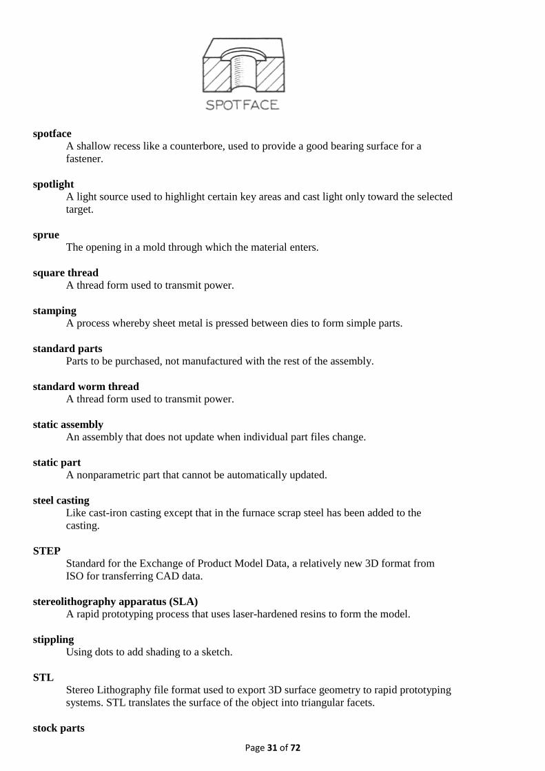
spotface To produce a round spot or bearing surface around a hole, usually with a spotfacer. The
spotface may be on top of a boss or it may be sunk into the surface.
Page 31 of 72
spotface A shallow recess like a counterbore, used to provide a good bearing surface for a
fastener.
spotlight A light source used to highlight certain key areas and cast light only toward the selected
target.
sprue The opening in a mold through which the material enters.
square thread A thread form used to transmit power.
stamping A process whereby sheet metal is pressed between dies to form simple parts.
standard parts Parts to be purchased, not manufactured with the rest of the assembly.
standard worm thread A thread form used to transmit power.
static assembly An assembly that does not update when individual part files change.
static part A nonparametric part that cannot be automatically updated.
steel casting Like cast-iron casting except that in the furnace scrap steel has been added to the
casting.
STEP Standard for the Exchange of Product Model Data, a relatively new 3D format from
ISO for transferring CAD data.
stereolithography apparatus (SLA) A rapid prototyping process that uses laser-hardened resins to form the model.
stippling Using dots to add shading to a sketch.
STL Stereo Lithography file format used to export 3D surface geometry to rapid prototyping
systems. STL translates the surface of the object into triangular facets.
stock parts

Page 32 of 72
Parts manufactured in quantity and kept in inventory for use in several different
products.
storyboard Pictures that depict the sequence and composition of key events in the animation.
subassembly A group of parts that fit together to create one functional unit.
surface modeling A type of three-dimensional modeling that defines only surfaces and edges. It resembles
an empty shell in the shape of the object
swage To hammer metal into shape while it is held over a swage, or die, which fits in a hole in
the swage block, or anvil.
sweat To fasten metal together by the use of solder between the pieces and by the application
of heat and pressure.
System International (SI) The metric system of units and measures.
system variables Settings that control the default operation of a CAD package.
tap
To cut internal threads.
tape Conical form given to a shaft or a hole. Also refers to the slope of a plane surface.
taper pin A small tapered pin for fastening, usually to prevent a collar or hub from rotating on a
shaft.
taper reamer A tapered reamer for producing accurate tapered holes, as for a taper pin.
temper To reheat hardened steel to bring it to a desired degree of hardness.
template A drawing with certain settings that can be used repeatedly as the basis for starting new
drawings. Also a prototype drawing.
tessellation lines Lines used to indicate surfaces in a wireframe view.
thermoplastics Plastics that melt when heated and set when cooled. In processing thermoplastics, the
mold is cooled to set the part.

Page 33 of 72
thermoset plastics Plastics that change from solid to liquid and back to solid when heated to become a new
cross-linked plastic.
third-angle projection The arrangement of orthographic views used in the United States and Canada.
thread angle The angle between the sides of the thread.
thread axis The center line of the screw where it appears rectangular.
thread depth The distance from the crest to the root of the thread measured perpendicular to the
thread axis.
thread form The shape of the thread.
tin A silvery metal used in alloys and for coating other metals, such as tin plate.
TIN Triangulated irregular networks.
tolerance The total amount that a measurement on an acceptable part may vary from the specified
dimension. Also the difference between the permitted minimum and maximum sizes of
a part.
tooling Any of the devices that work along with machinery to produce a part, such as jigs,
fixtures, molds.
top-down design Design that starts with the function of the entire system, then subsystems, and finally,
defining each part that must be manufactured and assembled to create the design.
total runout A measure of the cumulative variation measured over the entire surface as it is rotated
about a datum axis.
transformations Operations on the solid model that move it, scale it, or rotate it on the coordinate
system.
transition fit A tolerance that indicates that either a clearance or interference fit is acceptable.
translation Moving the model to a new location on the coordinate system.
trepan To cut a circular groove in the flat surface at one end of a hole.

Page 34 of 72
triangulated irregular networks (TIN) A system of triangular shapes used to define a surface.
tumble To clean rough castings or forgings in a revolving drum filled with scrap metal.
turn To produce, on a lathe, a cylindrical surface parallel to the center line.
tweaking Editing a surface model by moving individual control points.
twist drill A drill for use in a drill press.
undercut
A recessed cut or a cut with inwardly sloping sides.
unidirectional Using a single orientation for all text on a drawing. Letters are arranged horizontally
from left to right to be read from the bottom of the sheet.
unified thread A standard adopted during World War II to make it easier to find replacement parts
from allied countries.
unilateral tolerance A tolerance where the upper or lower deviation is 0.
update To regenerate the model or drawing using any new dimension values or changed
parameters.
upset To form a head or enlarged end on a bar or rod by pressure or by hammering between
dies.
URL Universal Resource Locator; the address format used to locate information on the
World Wide Web. Every document on the Web has a unique URL.
user coordinate systems A coordinate system defined by the user to assist in creating CAD geometry.
vacuum molding
A molding process that draws heated plastic sheets down into a shaped cavity.
vanishing point The location where the projectors converge in a perspective drawing.
vector A directional line. Also, a way of storing a graphic image as a set of mathematical

Page 35 of 72
formulas.
vector data Data that defines geometric entities by means of points and vectors (that define
direction and length). CAD software draws a particular entity on the screen based on
this vector information.
vertex The location where three or more plane surfaces intersect to form a point.
virtual prototype A 3D solid model used in lieu of a physical prototype to test and validate a design
before manufacture.
VRML Virtual Reality Modeling Language, a text-based language used to create 3D model that
the viewer can move around in.
web
A thin flat part joining larger parts. Also known as a rib.
weld Uniting metal pieces by pressure or fusion welding processes.
wireframe modeling A modeling method that represents the edges and contours of an object using lines,
circles, and arcs oriented in 3D space.
Woodruff key A semicircular flat key.
working drawings Drawings that convey all of the information needed to manufacture and assemble a
design.
WORM Write once read many.
write once read many (WORM) A storage media that cannot be overwritten.
wrought iron Iron of low carbon content useful because of its toughness, ductility, and malleability.
zoom
To change the magnification of the view of the model on screen.

Page 36 of 72
CAD Glossary
absolute coordinates
The exact location of a specific point in terms of x, y, and z from the fixed point of
origin.
absolute value
The numerical value or magnitude of the quantity, without regard to its positive or
negative sign.
alias
A short name that can be used to activate a command; you can customize command
aliases by editing the file acad.pgp.
Aliasing
The jagged appearance of a curved line or a straight line at an angle.
Aligned dimension
A dimension that shows the distance between two points at an angle.
ambient
The overall amount of light that exists in the environment of a rendered scene.
Ambient color
A color produced by ambient light.
Ambient light
Light that illuminates all surfaces equally.
And gate
An electronic logic symbol; if either input is zero, the output is zero.
angle brackets
A value that appears in angle brackets < > is the default option for that command,
which will be executed unless it is changed.
Angular dimension
A dimension that measures angles.
Annotations
Notes, text, tolerances, legends, and symbols.

Page 37 of 72
ANSI
American National Standards Institute; sets drafting standards.
Anti-aliasing
A means of shading the main pixels to reduce the appearance of aliasing.
aperture
A type of cursor resembling a small box placed on top of the crosshairs; used to select
in the object snap mode.
architectural units
Drawings made with these units are drawn in feet and fractional inches.
Array
A rectangular or circular pattern of graphical objects.
ASCII
American Standard Code for Information Interchange; a standard set of 128 binary
numbers representing keyboard information such as letters, numerals, and punctuation.
aspect ratio
The relationship of two dimensions to each other.
associative dimensioning
Dimensioning where each dimension is inserted as a group of drawing objects relative
to the points selected in the drawing. If the drawing is scaled or stretched, the
dimension values automatically update.
associative hatching
The practice of filling an area with a pattern which automatically updates when the
boundary is modified.
attribute
Text information associated with a block.
Attribute extraction file
A text file to which attribute data is written when it is extracted from a drawing.
attribute prompt
The prompt, which you define, that appears in the command area when you insert the
block into a drawing.

Page 38 of 72
attribute tag
A variable name that is replaced with the value that you type when prompted as you
insert the attribute block.
Attribute template
A file used to provide a format for extracted attributes.
Attribute value
The text that appears on the block when a block with an attribute is inserted.
AUI
Advanced User Interface; a user-interface enhancement that includes on-screen dialog
boxes, a menu bar that can be customized, pull-down menus, and icon menus.
Autolisp
A programming language contained within the AutoCAD program that is used for
writing programs for AutoCAD commands.
AutoSnap
A feature which displays a marker and description to indicate which object snap
location will be selected.
auxiliary view
An orthographic view of an object using a direction of sight other than one of the six
basic views (front, top, right-side, rear, bottom, left-side); used to show a surface that is
not parallel to the true size of any of the principal viewing planes.
ball tag
A circled number identifying each part shown in an assembly drawing. Also called a
bubble or balloon number.
base feature
In a feature-based model, the main feature from which other features are defined based
on the constraints put on the model.
base grip
The selected grip, used as the base point for hot grip commands.
Base point
The first point selected when copying, moving, rotating, inserting, or gripping objects.
baseline dimensioning

Page 39 of 72
A dimensioning method in which each successive dimension is measured from one
extension line or baseline.
basic view
One of the six standard views of an object: front, top, right side, rear, bottom, or left
side.
Baud rate
See bps.
bearing
The angle to turn from the first direction stated toward the second direction stated.
Bezier curve
A curve defined by a set of control points.
bicubic surface
A sculptured plane, mathematically describing a sculptured surface between three-
dimensional curves.
bidirectional associativity
Describes the link between the drawing and the model in a parametric modeler. If a
change is made to the model, the drawing is automatically updated to reflect the
change; if a change is made to the parametric dimensions in the drawing, both the
drawing and the model update automatically.
bilateral tolerances
Tolerances specified by defining a nominal dimension and the allowable range of
deviation from that dimension, both plus and minus.
Binary
The numerical base, base 2, by which computers operate. The electrical circuitry of a
computer is designed to recognize only two states, high and low, which easily translate
to logical and arithmetic values of 1 and 0. For example, the binary number 11101
represents the decimal number 29.
Bit (binary digit)
The smallest unit of computer data.
blip marks
Little crosses that appear on the screen, indicating where a location was selected.
block
A set of objects that have been grouped together to act as one, and can be saved and

Page 40 of 72
used in the current drawing and in other drawings.
block name
Identifies a particular named group of objects.
block reference
A particular insertion of a block into a drawing (blocks can be inserted more than once).
Board (printed circuit board)
Board onto which components are soldered and connected via etched circuits on the
board.
Boolean operators
Find the union (addition), difference (subtraction), and intersection (common area) of
two or more sets.
Boot
To turn the computer on and start a program.
bps (bits per second)
A unit of transmission; also called baud rate.
B-spline curve
A curve that passes near a set of control points
Buffer
An electronic logic symbol. An intermediate storage device (hardware or software)
between data handling units.
bump map
Converts color intensity or gray scale information to height, giving the appearance that
features are raised above the surface, similar to embossed letters.
Busy lamp
Indicator on the front of a disk drive that lights when the drive is writing or reading a
disk.
buttons
A method of selecting options by picking in a defined area of the screen resembling a
box or push button.
Byte
A string of 8 bits representing 256 different binary values. A kilobyte (Kbyte) is 1024

Page 41 of 72
bytes.
CAD
Computer-aided design; the use of graphics-oriented computer software for designing
and drafting applications.
CAD Standards
A standards file created to alert the operator when a user-defined standard graphic
procedure has been violated.
Cartesian coordinate system
A rectangular coordinate system created by three mutually perpendicular coordinate
axes, commonly labeled x, y, and z.
chained (continued) dimensioning
A dimensioning method in which each successive dimension is measured from
dimensioning the last extension line of the previous dimension.
chamfer
A straight line segment connecting two otherwise intersecting surfaces.
Chip (integrated circuit)
A miniature circuit made by etching electronic components on a silicon wafer.
chord length
The straight line distance between the start point and the endpoint of an arc.
circular view
A view of a cylinder in which it appears as a circle (looking into the hole).
circumscribed
Drawn around the outside of a base circle.
clearance fit
The space available between two mating parts, where the greatest shaft size always is
smaller than the smallest hole size, thus producing an open space.
Clipping
The process of setting the display boundaries of graphical items.
Clock
Electronic timer used to synchronize computer operations. A clock is an indication of

Page 42 of 72
the speed of the computer operations.
Cold boot
Starting the computer by turning it off and then on again.
CMYK
Cyan, Magenta, Yellow, and Black (key color). A system of creating colors by
specifying the percentage of each of the four colors.
colinear constraint
Lying on the same straight line.
Command
A word used to initiate a task.
command aliasing
The creation and use of alternative short names for commands, such as LA for Layer.
command prompt
The word or words in the command window that ask for the next piece of information.
command window
The lines of text below the graphics window that indicate the status of commands and
prompt for user input.
Com port
A communications port allowing data to flow into and out of the computer. Most
communication ports are serial ports. Digitizers and most plotters are connected to
communication ports. Most COM ports have pins rather than holes.
Configuration
A particular grouping of computer hardware as a functional unit. It may also include the
allocation of hardware resources and sometimes refers to software parameter settings.
construction plane
A plane that is temporarily defined during commands for creating new drawing objects.
context sensitive
Recognizes when you are in a command, and displays information for that command.
Continue dimension
A linear dimension that uses the second extension origin of the previous dimension as
its first extension origin.

Page 43 of 72
Coons patch
A bicubic surface interpolated between four edges.
Coordinate filters
An AutoCAD feature (also called XYZ point filters) that allows a user to extract
individual X, Y, and Z coordinate values from different points in order to create a new,
composite point.
coordinate system locator
An icon to help you visually refer to the current coordinate system.
coordinate values
Used to identify the location of a point, using the Cartesian coordinate system: X
represents the horizontal position on the X axis and Y represents the vertical position on
the Y axis. In a 3D drawing, Z represents the depth position on the Z axis.
Cpolygon
A crossing polygon that selects any object crossed by or contained within it.
cpu
Central processing unit; it is responsible for arithmetic computations, logic operations,
memory addresses, and data and control signal traffic in a computer.
Crosshairs
A cursor usually made up of two perpendicular lines on the display screen used to select
coordinate locations.
crosshatching
The practice of filling an area with a pattern to differentiate it from other components of
a drawing.
Crossing window
A window that selects any object crossed by or contained within the window.
CRT
Cathode-ray tube; the video display tube used with computers.
current layer
The layer you are working on. New drawing objects are always created on the layer that
is current.
cursor (crosshairs)

Page 44 of 72
A mark that shows the location of the pointing device in the graphics window of the
screen; used to draw, select, or pick icons, menu items, or objects. The appearance of
the cursor may change, depending on the command or option selected.
custom hatch pattern
A design that you have previously created and stored in the file acad.pat or another .pat
file of your own making to use to fill an area.
customize
To change the toolbars, menus, and other aspects of the program to show those
commands and functions that you want to use.
cutting edges
Objects used to define the portions to be removed when trimming an object.
cutting plane line
Defines the location on the object where the sectional view is taken.
Database
Related information organized and stored so that it can be easily retrieved and,
typically, used in multiple applications. A noncomputer example of a database is the
telephone directory.
datum surface
A theoretically exact geometric reference used to establish the tolerance zone for a
feature.
default
The value that AutoCAD will use unless you specify otherwise; appears in angle
brackets < > after a prompt.
default directory
The directory to which AutoCAD will save all drawing files unless instructed
otherwise.
Definition points (def points)
Points that appear when associative dimensions are created.
delta angle
The included angular value from the start point to the endpoint.
diameter symbol Indicates that the value is a diameter.

Page 45 of 72
DIESEL
Direct Interpretively Evaluated String Expression Language. A programming language
for customizing menu items.
difference
The area formed by subtracting one region or solid from another.
Diffuse color
The predominant color of an object
Digital signature
A signature to be used on an electronic drawing. The signature cannot be forged.
Digitizing tablet
A graphics input device that generates coordinate data. It is used in conjunction with a
puck or a stylus.
dimension line
Drawn between extension lines with an arrowhead at each end; indicates how the stated
dimension relates to the feature on the object.
dimension style
A group of dimension features saved as a set.
Dimension text
The text that appears in the dimension line.
dimension value
The value of the dimension being described (how long, how far across, etc.). The
dimension value is placed near the midpoint of the dimension line.
dimension variables
Features of dimensions that can be altered by the user; you control the features by
setting the variables using the Dimension Style dialog box.
dimensions
Describe the sizes and locations of a part or object so that it can be manufactured.
Direct distance entry
A method of defining points that allows the cursor to be moved to indicate the desired
direction, then the value is typed.
Directory

Page 46 of 72
Groups of files identified by a directory name.
Disk or diskette
A thin, flexible platter coated with a magnetic material for storing information.
Disk or diskette drive
A magnetic device that writes on and retrieves data from a disk.
Display resolution
The number of horizontal and vertical rows of pixels that can be displayed by a
particular graphics controller or monitor. For example, 640 columns and 350 rows of
pixels can be displayed by a standard EGA graphics controller and color monitor.
Display screen
A video-display tube or CRT used to transmit graphical information.
distance across the flats
A measurement of the size of a hexagon from one flat side to the side opposite it.
Dithering
Combining color dots to display more colors than are really available.
docked
Attached to any edge of the graphics window, as a toolbar can be.
DOS
Disk operating system; software that controls the operation of disk drives, memory
usage, and I/O in a computer.
draft angle
The taper on a molded part that makes it possible to easily remove the part from the
mold.
drag
To move an object on the screen and see it at the same time, in order to specify the new
size or location.
Drawing file
A collection of graphical data stored as a set (file) in a computer.
Drawing limits
The page size specified for a drawing. The grid shows the drawing limits.

Page 47 of 72
Drive
A device used to read or write information on a disk or diskette.
DXF
Drawing interchange file; a file format used to produce an ASCII description of an
AutoCAD drawing file.
edge view
A line representing a plane surface shown on its end.
Edge
A command used to change the visibility of a face.
Edit
To modify existing data
elements
Multilines comprising up to 16 lines.
Elevation
The Z value of an object with reference to the X-Y plane.
Embed
To copy an object from a source document into a destination document. An embedded
object has no link to the program from which the source document was taken.
Endpoint
The exact location on a line or curve where it terminates.
engineering units
Drawings made with these units are drawn in feet and decimal inches.
Enter key (<hard>)
Sometimes called the Return key; it signals the computer to execute a command or
terminate a line of text.
Entity
An AutoCAD term describing predefined graphical objects that are placed in the
drawing using a single command.

Page 48 of 72
Expansion option
Add-on hardware that expands power and versatility.
Expansion slot
Location inside the system unit for the connection of an optional printed circuit board.
Expansion slots for optional boards are available in many computers.
Explode
A command that separates blocks and poylines into separate line segments.
export
To save a file from one application as a different file type for use by another
application.
extension line
Relates a dimension to the feature it refers to.
extension line offset
Specifies a distance for the gap between the end of the extension line and the point that
defines the dimension.
Extents
The extreme boundary of a drawing without regard to the drawing limits.
External reference
A drawing file that is linked (or attached) to another drawing. Also called an xref in
AutoCAD.
extrusion
Creates a long three-dimensional strip with the shape of a close two-dimensional shape,
as if material had been forced through a shaped opening.
Extrusion
In AutoCAD, the process of assigning a thickness property to a given entity. The
direction of the extrusion is always parallel to the Z axis of the UCS in effect when the
entity was created.
Face
A bounded section of the surface of a modeled object.
falloff
The angle of the cone of light from a spotlight.

Page 49 of 72
Feature control frame
The box surrounding a geometric dimension.
feature
Any definable aspect of an object—a hole, a surface, etc.
file extension
The part of a file name that is composed of a period, followed by one to three
characters, and that helps you to identify the file type.
File
Information stored by a computer.
Fill
Solid coloring covering an area bounded by lines and/or curves.
fillet
An arc of specified radius that connects two lines, arcs, or circles, or a rounded interior
corner on a machined part.
Finite Element Analysis (FEA)
Numerical technique of approximately determining field variables such as
displacements or stresses in a domain. This is done by breaking down the domain into a
finite number of "pieces," also called "elements," and solving for the unknowns in those
elements.
Finite Element Modeling (FEM)
Process of breaking down a geometric model into a mesh, called the finite element
mesh model, that is used for finite element analysis.
Fit tolerance
The setting that determines how close a B-spline curve passes to the fit points.
floating
Refers to the toolbar's or command window's ability to be moved to any location on the
screen.
floating viewport
A window, created in paper space, through which you can see your model space
drawing; very useful for plotting the drawing, adding drawing details, showing an
enlarged view of the object, or showing multiple views of the object.
Floppy disk

Page 50 of 72
A circular plastic disk coated with magnetic material mounted in a square plastic
holder. It is used by a computer to store information for use later. It can be inserted or
removed from a floppy disk drive at will. It is also called a diskette.
flyout
A sub-toolbar that becomes visible when its representative icon on the main toolbar is
chosen.
Font
A distinctive text typeface, usually named and recognized by the aesthetic appearance
of its characters.
foreshortened
Appears smaller than actual size, due to being tipped away from the viewing plane.
Format
To prepare a disk to accept data.
fractional units
Drawings made with these units express lengths less than 1 as fractions (e.g., 15 1/4).
Freeze
A setting that keeps objects on selected layers from being displayed. A frozen layer is
not displayed, regenerated, or plotted. Freezing shortens regeneration time. A frozen
layer is not selected when the ALL selection option is used.
Function key
A key on the keyboard that can be assigned to perform a task. A function key is
typically used as a shortcut to a lengthy string of keystrokes.
generated layer
A layer created automatically (instead of by the user) during commands such as
SOLPROF.
global linetype scaling factor
The factor of the original size at which all lines in the drawing are displayed.
globe
Used to select the direction for viewing a three-dimensional model.
Gradient hatch
A smooth transition from light to dark creating the effect of light on 2-D objects.

Page 51 of 72
graphics window
The central part of the screen, which is used to create and display drawings.
Grid
An area on the graphics display covered with regularly spaced dots used as a drawing
aid.
Grips
Small squares that appear on objects selected before a command is activated. After the
grips appear the objects can be edited by selecting one of the squares to make it hot and
toggling through the available grip modes.
group
A named selection set of objects.
handle number
A unique identifier assigned to each AutoCAD drawing object, including viewports.
Handle
An alphanumeric tag that AutoCAD assigns to every object.
Hard copy
A paper printout of information stored in a computer.
Hard disk
A rigid magnetic storage device that provides fast access to stored data.
Hardware
The electronic and mechanical parts of a computer.
Hatching
A regular pattern of line segments covering an area bounded by lines and/or curves.
heads-up
You can enter the command while looking at the screen; by picking an icon, for
example, you do not need to look down to the keyboard to enter the command.
hidden line
Represents an edge that is not directly visible because it is behind or beneath another
surface.

Page 52 of 72
High density
The storage capacity of a disk or disk drive that uses high-capacity disks.
highlight
A change of color around a particular command or object, indicating that it has been
selected and is ready to be executed or worked on in some way.
HLS
Hue, lightness, and saturation. A system of defining color by specifying the amount of
these three values.
hot grips
A method for editing an already drawn object using only the pointing device, without
needing to use the menus, toolbars, or keyboard.
hotspot
The angle of the cone of light for the brightest area of the beam of a spotlight.
Hz (hertz)
A unit of frequency equal to one cycle per second.
Icon
A graphical symbol typically used to convey a message or represent a command on the
display screen.
i-drop
Blocks that can be taken from a web page or other location and dropped onto the
current drawing.
image tile
An active picture which displays dialog box choices as graphic images rather than
words.
implied Crossing mode
When this mode is activated, the first corner of a box is started when you select a point
on the screen that is not on an object in the drawing. If the box is drawn from right to
left, everything that partially crosses as well as items fully enclosed by the box are
selected.
implied Windowing mode
When this mode is activated, the first corner of a box is started when you select a point
on the screen that is not on an object in the drawing. If the box is drawn from the left to

Page 53 of 72
right, a window is formed that selects everything that is entirely enclosed in the box.
import
To open and use a file created by a different application than the one being used.
inclined surface
Slanted at an angle, a surface that is perpendicular to one of the three principal views
and tipped away from the other principal views.
included angle
The angular measurement along a circular path.
inscribed
Drawn inside a base circle.
inspection
The act of examining the part against its specifications.
instance
Each single action of a command.
intensity
The brightness level of a light source.
Interface
A connection that allows two devices to communicate.
intersection
The point where two lines or surfaces meet, or the area shared by overlapping regions
or solid models.
Inverter gate
A symbol used to draw an electronic logic circuit; for inputs of 1, the output is 0, for
inputs of 0, the output is 1.
I/O
Input/output; a mechanism by which a computer accepts or distributes information to
periphreal devices such as plotters, printers, disk drives, and modems.
ISO
International Standards Organization, an organization that sets international standards
for drawings. Also, an abbreviation for isometric, a view or drawing of an object in
Page 54 of 72
which the projections of the X, Y, and Z axes are spaced 120° apart, and the projection
of the Z axis is vertical.
Isometric snap style
A snap style that sets the grid and snap to the isometric angles of 30°, 30°, and 90°.
K (kilobyte)
1024 bytes.
layer
A method of separating drawing objects so they can be viewed individually or stacked
like transparent acetates, allowing all layers to show. Used to set color and linetype
properties for groups of objects.
Layout
The tab that allows paper space viewports to be created with scaled insertions of the
model space drawing.
leader line
A line from a note or radial dimension that ends in an arrowhead pointing at the feature.
limiting element
The outer edge of a curved surface.
limiting tolerances
Tolerances specified by defining an upper and lower allowable measurement.
Linetype
Sometimes called line font, it represents the appearance of a line. For example, a
continuous line has a different linetype than a dashed line.
Lineweight
A setting in the Layer Manager that allows lines on any layer to be assigned a specific
width.
Link
A copy of a source document that is connected to the source program so that any
changes to the source document are reflected in the copy.
Load
To enter a program into the computer's memory from a storage device.

Page 55 of 72
lock
To prohibit changes to a layer, although the layer is still visible on the screen.
M (megabyte)
One million bytes.
Macro
A single command made up of a string of commands.
major arc
An arc which comprises more than 180° of a circle.
major axis
The long axis of symmetry across an ellipse.
manufacture
To create a part according to its specifications.
mass properties
Data about the real-world object being drawn, such as its mass, volume, and moments
of inertia.
matrix
An array of vertices used to generate a surface.
Memory
An electronic part of a computer that stores information.
Menu
A display of programs or tasks.
menu bar
The strip across the top of the screen showing the names of the pull-down menus, such
as File, Edit, etc.
MHz (megahertz)
One thousand hertz.
Microprocessor
An integrated circuit "chip" (or set of chips) that acts as the CPU of a computer.

Page 56 of 72
minor axis
The short axis of symmetry across an ellipse.
mirror line
A line that defines the angle and distance at which a reversed image of a selected object
will be created.
Mirror
To create the reverse image of selected graphical items.
miter line
A line drawn above the side view and to the right of the top view, often drawn from the
top right corner of the front view, used to project features from the side view onto the
top view of an object.
Mode
A software setting or operational state.
model space
The AutoCAD drawing database, when an object exists as a three-dimensional object.
Model
A two- or three-dimensional representation of an object.
Modeless dialog box
A dialog box that remains on the screen while the command is executed.
Modem (modulator-demodulator)
A device that links computers via a telephone line.
Monochrome
A video display that features different shades of a single color.
Motherboard
The main printed circuit board in a computer to which all other boards are connected.
Mouse
A hand-operated, relative-motion device resembling a digitizer puck used to position
the cursor on a computer display screen.
Nand gate

Page 57 of 72
A symbol used to draw an electronic logic circuit; when both inputs are 1, output is 0,
when any input is 0, output is 1.
Network
An electronic linking of computers for communication.
Node
An object snap option that allows you to snap to points.
Nor gate
A symbol used to draw an electronic logic circuit; when both inputs are 0, output is 1,
any input of 1, output is 0.
normal surface
A surface that is perpendicular to two of the three principal orthographic views and
appears at the correct size and shape in a basic view.
Normal
Perpendicular.
noun/verb selection
A method for selecting an object first and then the command to be used on it.
Numerical control (NC)
Programmable automation of machine tools.
nurb
A cubic spline curve.
NURBS
Nonuniform rational B-spline curve. A curve or surface defined by control points.
Object
Also called entity; any element such as text, lines, circles, arcs, dimensions, hatching,
and polylines used in AutoCAD.
offset distance
Controls the distance from an existing object at which a new object will be created.

Page 58 of 72
OLE
Object linking and embedding. Objects from a source document are copied into a
destination document. When the object is selected in the destination document, the
program used to create the source document is activated.
Operating system
Also called the disk operating system; software that manages computer resources and
allows a user access and control.
options
The choices associated with a particular command or instruction.
Or gate
A symbol used to draw an electronic logic circuit; any input of 1 results in output of 1,
when both inputs are 0, output is 0.
Origin
The intersection point of the axes in a coordinate system. For example, the origin of a
Cartesian coordinate system is the point at which the X, Y, and Z axes meet (0, 0, 0).
Ortho mode
An AutoCAD setting that permits only horizontal or vertical input from the graphical
pointing device (mouse, puck, or stylus).
Orthographic projection
The 2-D representation of a 3-D object without perspective. In drafting, it is typically
the front, top, and right-side views of an object.
orthographic view
A two-dimensional drawing used in representing a three-dimensional object. A
minimum of two orthographic views are necessary to show the shape of a three-
dimensional object, because each view shows only two dimensions.
Osnap
Object snap, an AutoCAD setting that allows the user to specify point locations based
on existing geometry. This allows for the graphical selection of the precise location of
midpoints and endpoints of lines, center points and tangent points of circles and arcs,
and the like.
output file
The file to which attribute data is extracted.
overall dimensions

Page 59 of 72
The widest measurements of a part; needed by manufacturers to determine how much
material to start with.
override mode
When the desired object snap mode is selected during each command it is to be used
for.
Overwrite
To store information at a location where information is already stored, thus destroying
the original information.
palette
A type of toolbar, usually divided into areas, that allows for quick selection of items. In
AutoCAD, Tool Palettes are used to organize blocks and hatches in a location where
they can be dragged into a drawing (similar to the way paint is held on an artist's palette
for quick access).
Pan
Redefines the display boundaries without changing magnification; analogous to
panning with a camera.
paper space
A mode that allows you to arrange, annotate, and plot different views of a model in a
single drawing, as you would arrange views on a piece of paper.
Parallel interface
Interface that communicates 8, 16, or 32 bits at a time.
Parallel port
A connector on the back of the computer that usually has holes rather than pins. This
connector always has 25 connections. Most printers are connected to parallel ports.
Parallel printer
A printer with a parallel interface.
parametric
A modeling method that allows you to input sizes for and relatinships between the
features of parts. Changing a size or relationship will result in the model being updated
to the new apperance.
partial auxiliary view
An auxiliary view that shows only the desired surfaces.

Page 60 of 72
parts list
Provides information about the parts in an assembly drawing, including the item
number, description, quantity, material, and part number.
pc3 file
The plotter configuration file. It contains all the specific information needed to operate
a particular plotter or printer.
Peripheral
An input or output device not under direct computer control.
perspective icon
A cube drawn in perspective that replaces the UCS icon when perspective viewing,
activated by the 3D Dynamic View command, is in effect.
Perspective projection
The simulation of distance by representing parallel lines converging at a vanishing
point.
Pick button
The button on any pointing device such as a mouse that is used to pick objects or define
points—usually the left mouse button.
pictorial full section
A section view showing an object cut in half along its vertical center line.
pin registry
A process in which a series of transparent sheets are punched with a special hole pattern
along one edge, allowing the sheets to be fitted onto a metal pin bar. The metal pin bar
keeps the drawings aligned from one sheet to the next. Each sheet is used to show
different map information.
Pixels (picture elements)
Tiny dots that make up a screen image.
plan view
The top view or view looking straight down the Z axis toward the X-Y plane.
Plot style
A file containing all the pen assignments, fill style, line endings, and other elements that
control how a drawing is plotted.
Plotter

Page 61 of 72
A computer-controlled device that produces text and images on paper or acetate by
electrostatic, thermal, or mechanical means (with a pen).
plus/minus tolerances
Another name for variance tolerances.
PMP file
Plot model parameter; a file that contains the custom plotter calibration and paper size
data to operate a specific printer or plotter.
Point
A location or dot in 3D space specified by X, Y, and Z coordinates.
point filter
Option that lets you selectively find single coordinates out of a point's three-
dimensional coordinate set.
point light
A light source similar to a bare light bulb that casts light in every direction.
pointer
An indicator established from the current drawing to the original drawing, or external
reference.
polar array
A pattern created by repeating objects over and over in a circular fashion.
polar coordinates
In AutoCAD, the location of a point, defined as a distance and an angle from another
specified point, using the input format @DISTANCE<angle.< dd="">
</angle.<>
polygon
A closed shape with sides of equal length.
Polygon window
A selection window in the shape of a polygon. An item must be contained entirely
inside the window to be selected.
polyline
A series of connected objects (lines or arcs) that are treated as a single object.
Port

Page 62 of 72
A connection on a computer where a peripheral device can be connected.
precedence
When two lines occupy the same space, precedence determines which one is drawn.
Continuous lines take precedence over hidden lines, and hidden lines take precedence
over center lines.
primitives
Basic shapes that can be joined together or subtracted from each other to form more
complex shapes.
Processor
A computer on a chip.
profile
A two-dimensional view of a three-dimensional solid object created using the Solprof
(Setup Profile) command.
Program
A detailed list of instructions that will be quickly, precisely, and blindly followed by a
computer.
project
To transfer information from one view of an object to another by aligning the views and
using projection lines.
projection lines
Horizontal lines that stretch from one view of an object to another to show which line
or surface is which.
Prompt
A message from the computer software requesting a response from the user.
Properties toolbar
Contains the icons whose commands control the appearance of the objects in your
drawing.
prototype drawing
A drawing saved with certain settings that can be used repeatedly as the basis for
starting new drawings.
Puck
A hand-operated device with one or more buttons (resembling a mouse) that operates in
conjunction with a digitizing tablet; also called a transducer.

Page 63 of 72
quadrant point
Any of the four points that mark the division of a circle or arc into four segments: 0°,
90°, 180°, and 270°.
RAM (random-access memory)
Temporary read/write memory that stores information only when the computer is on.
ray tracing
The method of calculating shading by tracking reflected light rays hitting the object.
Read
To extract data from a storage device such as a floppy disk or hard disk.
real-world units
Units in which drawings in the database are drawn; objects should always be drawn at
the size that the real object would be.
rectangular array
A pattern created by repeating objects over and over in columns and rows.
rectangular view
A view of a cylinder in which it appears as a rectangle (looking from the side).
reference surface
A surface from which measurements are made when creating another view of the
object.
reflection
The degree to which a surface bounces back light.
Reflection color
The color of a highlight on shiny material.
refraction
The degree to which an object changes the angle of light passing through it.
regenerate
To recalculate from the drawing database a drawing display that has just been zoomed
or had changes made to it.

Page 64 of 72
region
A two-dimensional area created from a closed shape or a loop.
relative coordinates
The location of a point in terms of the X and Y distance, or distance and angle, from a
previously specified point @X,Y.
rendered
Lighting effects, color, and shape applied to an object in a single two-dimensional view.
resolution
Refers to how sharp and clear an image appears to be and how much detail can be seen;
the higher the resolution, the better the quality of the image. This is determined by the
number of colors and pixels the computer monitor can display.
Return button
The button on a pointing device used to accept an entry—usually the right mouse
button.
Revision Cloud
A command used to mark changes or corrections when drawings are checked.
revolution
Creating a three-dimensional object by sweeping a two-dimensional polyline, circle, or
region about a circular path to create a symmetrical solid that is basically circular in
cross-section.
RGB
Red, green, blue. A system of creating colors using percentages of these three colors.
Right-hand rule
Using the fingers of the right hand to remember the relative directions of the positive X,
Y, and Z axes of a Cartesian coordinate system. It is particularly useful in AutoCAD in
visualizing UCS orientations.
ROM (read-only memory)
Permanent computer memory that cannot be written to.
roman
A font.
root page

Page 65 of 72
The original standard screen menu column along the right side of the screen, accessed
by picking the word AutoCAD at the top of the screen.
roughness
The apparent texture of a surface. The lower the surface roughness, the more reflective
the surface will be.
round
A convex arc, or a rounded external corner on a machined part.
RS-232C
Standard interface cable for serial devices.
running mode
When the current object snap mode is automatically used any time a command calls for
the input of a point or selection.
Running object snap
An object snap mode, such as endpoint, that is automatically active when a point is
selected.
Save
To store data on a disk.
scale factor
The multiple or fraction of the original size of a drawing object or linetype at which it is
displayed.
Script file
A file with the extension .scr created in a text editor that executes a set of AutoCAD
commands.
section lines
Show surfaces that were cut in a section view.
section view
A type of orthographic view that shows the internal structure of an object; also called a
cutaway view.
Selection window
A window used to select objects. Any object must be contained entirely within the
window to be selected.

Page 66 of 72
selectable group
A named selection set in which picking on one of its members selects all members that
are in the current space, and not on locked or frozen layers. An object can belong to
more than one group.
selection filters
A list of properties required of an object for it to be selected.
selection set
All of the objects chosen to be affected by a particular command.
Serial interface
An interface that communicates information one bit at a time.
Serial port
A connector on the back of the computer that has pins rather than holes. This connector
may have either 9 or 25 pins.
Serial printer
A printer with a serial interface (receives information one bit at a time).
session
Each use, from loading to exiting, of AutoCAD.
Shade Plot
A feature located in the Plot dialog box and the Properties palette that allows rendered
drawings to be printed as displayed on the screen.
shape-compiled font
Character shapes drawn in AutoCAD using vectors.
sign
Positive or negative indicator that precedes a centermark value.
slicing plane
A plane that is defined for use in slicing a solid object. During the Slice command, the
object can be removed on either side of the slicing plane or the selected object can be
parted along the slicing plane and both sides can be retained.
Snap
A means of setting a pointing device to stop at specified intervals on an invisible grid.

Page 67 of 72
Software
Computer programs.
solid modeling
A type of three-dimensional modeling that represents the volume of an object, not just
its lines and surfaces; this allows for analysis of the object's mass properties.
spotlight
A light source used to highlight certain key areas and cast light only toward the selected
target.
Standard toolbar
Contains the icons which control file operation commands.
status bar
The rectangular area at the bottom of screen that displays time and some command and
file operation information.
style
Controls the name, font file, height, width factor, obliquing angle, etc.
Stylus
An input device used like a digitizer puck but that looks like a pen.
submenu
A list of available options or commands relating to an item chosen from a menu.
surface modeling
A type of three-dimensional modeling that defines only surfaces and edges so that the
model can be shaded and have hidden lines removed; resembles an empty shell in the
shape of the object.
Surface of revolution
A surface generated by revolving a profile curve around an axis.
swatch
An area that shows a sample of the color or pattern currently selected.
sweeping
Extrusion along a non-linear path rather than a straight line.
System board

Page 68 of 72
The main printed circuit board inside the system unit into which other boards are
connected.
System unit
The component that contains the computer parts, disk drives, and option boards.
System variable
A setting that determines how the AutoCAD program operates.
target area
The square area on an object snap aperture, in which at least part of the object to be
selected must fit.
template drawing
A drawing with the extension .dwt having certain settings that can be used repeatedly as
the basis for starting new drawings. Any drawing can be renamed and used as a
template.
template file
Specifies the file format for the Extract Attribute command as .cdf or .sdf.
tessellation lines
To cover a surface with a grid or lines, like a mosaic. Tessellation lines are displayed on
a curved surface to help you visualize it; the number of tessellation lines determines the
accuracy of surface area calculations.
Text style
A collection of settings that determine the appearance of text.
Thaw
A setting that displays frozen layers when that layer is also on.
Thickness
A setting that gives height (the Z dimension) to certain objects such as solids, circles,
and polylines, making them 3-D objects.
threshold value
Determines how close vertices must be in order to be automatically welded during the
rendering process.
through point
The point through which the offset object is to be drawn.

Page 69 of 72
tiled viewports
Multiple viewports that cannot overlap. They must line up next to each other, like tiles
on a floor.
tilemode
An AutoCAD system variable that controls the use of tiled or floating viewports or
paper space.
title bar
The rectangular area at the top of the screen which displays the application and file
names.
toggle
A switch that turns certain settings on and off.
tolerance
The amount that a manufactured part can vary from the specifications laid out in the
plans and still be acceptable.
tool tip
The name of the icon that appears when you hold the cursor over the icon.
toolbar
A strip containing icons for certain commands.
Tracking
A means of locating a point relative to other points on the drawing.
transparency
A quality that makes objects appear clear, like glass, or somewhat clear, like colored
liquids.
transparent command
A command that can be selected while another command is operating.
typing cursor
A special cursor used in dialog boxes for entering text from the keyboard.
UCS icon
Indicates the current coordinate system in use and the direction in which the coordinates
are being viewed in 3D drawings.

Page 70 of 72
unidirectional dimensioning
The standard alignment for dimension text, which is to orient the text horizontally.
union
The area formed by adding two regions or solid models together.
Unit
A user-defined distance, such as inches, meters, or miles.
units
AutoCAD can draw figures using metric, decimal, scientific, engineering, or
architectural measurement scales. These are set with the Units command.
update
To regenerate the active part or drawing using any new dimension values or changed
sketches.
User Coordinate System (UCS)
A set of x, y, and z coordinates whose origin, rotation, and tilt are defined by the user.
You can create and name any number of User Coordinate Systems.
user-defined hatch pattern
A predefined hatch pattern for which you have specified the angle, spacing, and/or
linetype.
variance tolerances
Tolerances specified by defining a nominal dimension and the allowable range of
deviation from that dimension; includes bilateral and unilateral tolerances.
vector
A directional line. Also, a way of storing a graphic image as a set of mathematical
formulas.
Venn diagram
Pictorial description named after John Venn, an English logician, where circles are used
to represent set operations.
View
A graphical representation of a 2-D drawing or 3-D model from a specific location
(viewpoint) in space.
viewpoint

Page 71 of 72
The direction from which you are viewing a three-dimensional object.
viewport
A "window" showing a particular view of a three-dimensional object.
virtual screen
A file containing only the information displayed on the screen. AutoCAD uses this to
allow fast zooming without having to regenerate the original drawing file.
Virtual screen display
The area of the display where AutoCAD can zoom in or out without regenerating the
drawing.
Windows close button
A button in the upper right corner of a window that closes the window.
Wireframe model
A 2-D or 3-D representation of an object consisting of boundary lines or edges of an
object.
wireframe modeling
A type of three-dimensional modeling that uses lines, arcs, circles, and other objects to
represent the edges and other features of an object; so called because it looks like a
sculpture made from wires.
World Coordinate System (WCS)
AutoCAD's system for defining three-dimesional model geometry using x, y, and z
coordinate values; the default orientation is a horizontal X axis with positive values to
the right, a vertical Y axis with positive values above the X axis, and a Z axis that is
perpendicular to the screen and has positive values in front of the screen.
World Coordinates
The basis for all user coordinate systems.
Wpolygon
See polygon window.
Write
To record or store information in a storage device.
Write-enable notch
Slot on the side of a floppy disk that, when uncovered, permits the disk to be written on.
Page 72 of 72
Write-protect
To cover a floppy disk write-enable notch, thus preventing writing on the disk.
Xref
See external reference.
XYZ point filters
A means of individually extracting the X, Y, and Z coordinates of points to specify a
new point.
Zoom
The process of reducing or increasing the magnification of graphics on the display
screen.