Engineering Failure Analysis - mae.sut.ac.irmae.sut.ac.ir/People\Courses\61\Faliure...
8
Short communication Failure analysis of a carbon steel screw under the service in the presence of hydrogen sulphide F. Nasirpouri ⇑ , H. Alizadeh, M. Hosseingholizadeh Department of Materials Engineering, Sahand University of Technology, Tabriz 51335-1996, Iran 1. Introduction The petroleum industry generally has different processes which bring a wide variety of corrosive environments in contact with structural materials in service. Each year, tens of millions of dollars are spent to replace or repair pipes and vessels that suffer excessive localized metal loss, stress corrosion cracking (SCC) or hydrogen embrittlement (HE). One of the most com- mon failures in the industry would happen due to the brittle fracture known as sulphide stress cracking (SSC) when the sur- rounding environment contains sulphurous compounds such as hydrogen sulphide (H 2 S) [1]. Under a wet H 2 S atmosphere, steels become susceptible to SSC. Under such circumstances atomic hydrogen, resulted from an electrochemical reaction between the metal and the H 2 S-containing medium enters the steel at the corroding sur- face. Atomic hydrogen, in turn, can partly be absorbed into the steel. In the absence of applied stress, the diffused hydrogen could cause blistering or hydrogen induced cracking (HIC) initiated at hard phase constituents and non-metallic inclusions. In the presence of applied and residual stress, the failure process can occur either by sulphide stress corrosion cracking (SSCC) through hydrogen embrittlement or stress oriented hydrogen induced cracking (SOHIC). The latter occurs mainly in lower strength steels, such as API pipeline grades [2]. SSC is a form of hydrogen stress cracking resulting from absorption of atomic hydrogen produced by the sulphide corrosion process on the metal surface [3]. All variables known to influence SSC of iron-based alloys are classified into two major categories: (i) environmental ef- fects that include hydrogen sulphide concentration (or pressure), temperature and applied potential, and (ii) mechanical and metallurgical variables such as alloy composition, microstructure, heat treatment, cold work, hardness or strength level, and surface condition [4–10]. One particular study has shown that tempered martensite is a less sensitive phase to SSC, meaning that the higher the mechanical properties of steel, the lower the SSC resistance. The higher volume fraction of martensite with a minimum value of 95% is suggested to make the steel SSC resistant [11]. Even in the presence of sodium chloride beside hydrogen sulphide, steels with a martensitic microstructure has the highest corrosion rate up to two orders of magnitude higher than that for ferritic–bainitic or ferritic microstructures [12]. Environmental variables that control SSC and accelerate its effect include low pH, high partial pressure of hydrogen sul- phide, increasing chloride concentration, temperature and implied potential increasing [11]. SSC is most probably found in hard weld and heat affected zones and in high strength components including bolts, relief valve springs, valve trim, compres- sor shafts, sleeves, springs and can occur throughout the refinery wherever there is a wet H 2 S environment present [3]. Screw steels are often subject to environments containing hydrogen sulphide (H 2 S) in the presence of tensile stress. Under specified conditions, these steels are known to be highly resistive against a severe sulphide stress cracking (SSC) failure. For conventional industrial applications the materials are assumed to have high SSC susceptibility if the hardness of screw steels exceeds 22 HRC (equivalent to 550 MPa yield strength) [13]. Also about pipeline, EN ISO 15156-1 standard implies that the hardness of welds, heat-affected zones and base metal of the pipeline play an important role in determining its sulphide stress cracking susceptibility, which is high in regions presenting hardness greater than 22 HRC [14–16]. 1350-6307/$ - see front matter Ó 2011 Elsevier Ltd. All rights reserved. doi:10.1016/j.engfailanal.2011.07.001 ⇑ Corresponding author. Tel.: +98 412 3459450; fax: +98 412 3444333. E-mail address: [email protected] (F. Nasirpouri). Engineering Failure Analysis 18 (2011) 2316–2323 Contents lists available at ScienceDirect Engineering Failure Analysis journal homepage: www.elsevier.com/locate/engfailanal
Transcript of Engineering Failure Analysis - mae.sut.ac.irmae.sut.ac.ir/People\Courses\61\Faliure...

Engineering Failure Analysis 18 (2011) 2316–2323
Contents lists available at ScienceDirect
Engineering Failure Analysis
journal homepage: www.elsevier .com/locate /engfai lanal
Short communication
Failure analysis of a carbon steel screw under the service in the presenceof hydrogen sulphide
F. Nasirpouri ⇑, H. Alizadeh, M. HosseingholizadehDepartment of Materials Engineering, Sahand University of Technology, Tabriz 51335-1996, Iran
1. Introduction
The petroleum industry generally has different processes which bring a wide variety of corrosive environments in contactwith structural materials in service. Each year, tens of millions of dollars are spent to replace or repair pipes and vessels thatsuffer excessive localized metal loss, stress corrosion cracking (SCC) or hydrogen embrittlement (HE). One of the most com-mon failures in the industry would happen due to the brittle fracture known as sulphide stress cracking (SSC) when the sur-rounding environment contains sulphurous compounds such as hydrogen sulphide (H2S) [1].
Under a wet H2S atmosphere, steels become susceptible to SSC. Under such circumstances atomic hydrogen, resultedfrom an electrochemical reaction between the metal and the H2S-containing medium enters the steel at the corroding sur-face. Atomic hydrogen, in turn, can partly be absorbed into the steel. In the absence of applied stress, the diffused hydrogencould cause blistering or hydrogen induced cracking (HIC) initiated at hard phase constituents and non-metallic inclusions.In the presence of applied and residual stress, the failure process can occur either by sulphide stress corrosion cracking(SSCC) through hydrogen embrittlement or stress oriented hydrogen induced cracking (SOHIC). The latter occurs mainlyin lower strength steels, such as API pipeline grades [2]. SSC is a form of hydrogen stress cracking resulting from absorptionof atomic hydrogen produced by the sulphide corrosion process on the metal surface [3].
All variables known to influence SSC of iron-based alloys are classified into two major categories: (i) environmental ef-fects that include hydrogen sulphide concentration (or pressure), temperature and applied potential, and (ii) mechanicaland metallurgical variables such as alloy composition, microstructure, heat treatment, cold work, hardness or strength level,and surface condition [4–10].
One particular study has shown that tempered martensite is a less sensitive phase to SSC, meaning that the higher themechanical properties of steel, the lower the SSC resistance. The higher volume fraction of martensite with a minimum valueof 95% is suggested to make the steel SSC resistant [11]. Even in the presence of sodium chloride beside hydrogen sulphide,steels with a martensitic microstructure has the highest corrosion rate up to two orders of magnitude higher than that forferritic–bainitic or ferritic microstructures [12].
Environmental variables that control SSC and accelerate its effect include low pH, high partial pressure of hydrogen sul-phide, increasing chloride concentration, temperature and implied potential increasing [11]. SSC is most probably found inhard weld and heat affected zones and in high strength components including bolts, relief valve springs, valve trim, compres-sor shafts, sleeves, springs and can occur throughout the refinery wherever there is a wet H2S environment present [3].
Screw steels are often subject to environments containing hydrogen sulphide (H2S) in the presence of tensile stress. Underspecified conditions, these steels are known to be highly resistive against a severe sulphide stress cracking (SSC) failure. Forconventional industrial applications the materials are assumed to have high SSC susceptibility if the hardness of screw steelsexceeds 22 HRC (equivalent to 550 MPa yield strength) [13]. Also about pipeline, EN ISO 15156-1 standard implies that thehardness of welds, heat-affected zones and base metal of the pipeline play an important role in determining its sulphidestress cracking susceptibility, which is high in regions presenting hardness greater than 22 HRC [14–16].
1350-6307/$ - see front matter � 2011 Elsevier Ltd. All rights reserved.doi:10.1016/j.engfailanal.2011.07.001
⇑ Corresponding author. Tel.: +98 412 3459450; fax: +98 412 3444333.E-mail address: [email protected] (F. Nasirpouri).
F. Nasirpouri et al. / Engineering Failure Analysis 18 (2011) 2316–2323 2317
On the effect of the alloying upon the SSC resistance, hydrogen permeability tests have shown that the addition of nio-bium as an alloying element decreases the hydrogen entrapment from sour working media. Niobium micro-alloying is,therefore, a suitable way to improve the SSC resistance of high-strength steels. Also, both vanadium and molybdenum havean improving effect on the SSC resistance of steels. The useful effect of chromium addition is evidenced when it is alloyedbetween 0.07 and 1.3 %wt, while a ‘‘threshold effect’’ seems also to be observed because the SSC resistance does not changeanymore above 1.3% of Cr. In H2S saturated synthetic sea water at pH 5, copper alloying has been reported to have a bene-ficial effect on the general corrosion of steels [11].
Zhao et al. realized that steels with acicular ferrite exhibit a better SSC resistance than those with a martensitic micro-structure [14]. It is currently recognized that the best suited grades for manufacture of SSC-resistant components are steelsof the AISI 4100 series with a tempered martensite microstructure. However, because of the development of deep and sourwells in the recent years, there is an increasing demand for higher strength H2S-resistant steels so that it is now difficult tomeet the requirements of customers by using these grades [8,14].
In this paper, we report a failure analysis on a carbon steel screw broken after a short time service in H2S containingenvironment.
2. Material and methods
A ruptures screw was achieved from a petroleum industry. The processing unit in which the screw was failed contained astream flow containing H2S gas. The screw was made of steel whose composition was analyzed using quantumetry and isshown in Table 1. According to the manufacturer’s data sheet, the screw was subjected to rolling procedures.
The failed screw was first investigated by visual examinations to record any obvious failure remarks. Different samplesfrom different parts of the specimen were selected for metallographic, electron microscopy and hardness examinations.Metallography samples were prepared from cross sections of cracked and sound regions. Samples were etched in Nital 2%solution. Scanning electron microscopy (SEM- MV2300 Cam Scan) and energy dispersive X-ray spectroscopy (EDS-Oxfordinstruments) were used to study the surface morphology and chemical composition of fractured surface and also corrosionproducts.
Microhardness in Rockwell was performed using 100 g load with a dwell time of 15 s to obtain the hardness profilearound the cracked area.
3. Results
3.1. Visual examinations
Fig. 1 shows an image of the failed screw taken in the lab after the failure. Visual test was primarily performed and re-vealed that a thin yellowish film exists on the specimen. Several cracks were also detected on the outer surface of the screw,as shown in Fig. 2. It was observed that the cracks have propagated from outer surface into the center of the sample. Cracksobserved have been developed without any deformation in the material.
3.2. Metallographical examinations
Fig. 3 shows optical micrographs taken from different parts of the sample. Fig. 4 illustrates an optical micrograph takenfrom the cross section of mainly cracked region. The cracks detected on the surface of the screw are shown in Fig. 5. Thesecracks like large crakes produced on the surface and grew into the center of the screw.
Metallographical examinations after polishing and etching procedures under appropriate conditions imply that themicrostructure of steel is fine grain bainite near to the outer surface, in the center and around the cracks developed inthe screw.
Table 1Elemental chemical composition of the screw steel taken from the core of the specimen.
C Si Mn P S Cr Mo Ni Al Co
0.354% 0.211% 0.730% 0.028% 0.031% 1.160% 0.210% 0.076% 0.016% 0.014%
Cu Nb Ti V W Pb Sn Mg As Zr
0.204% <0.002% 0.004% 0.005% 0.020% <0.001% 0.019% <0.001% 0.016% 0.002%
Ca Ce Sb Ta Zn N Fe
0.001% <0.001% <0.001% 0.054% <0.001% 0.011% 96.834%
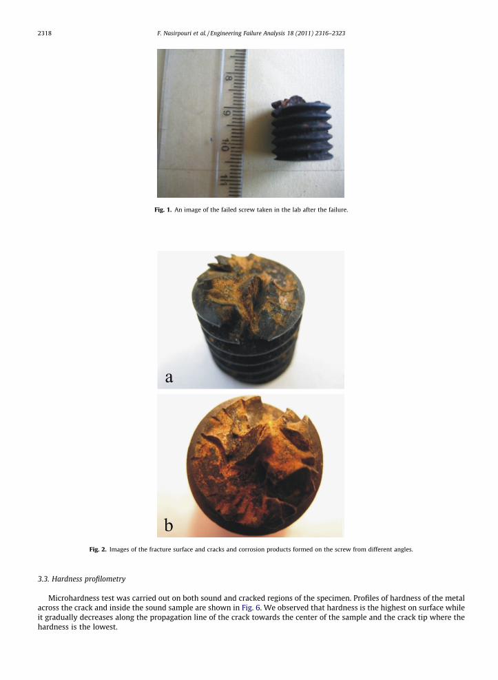
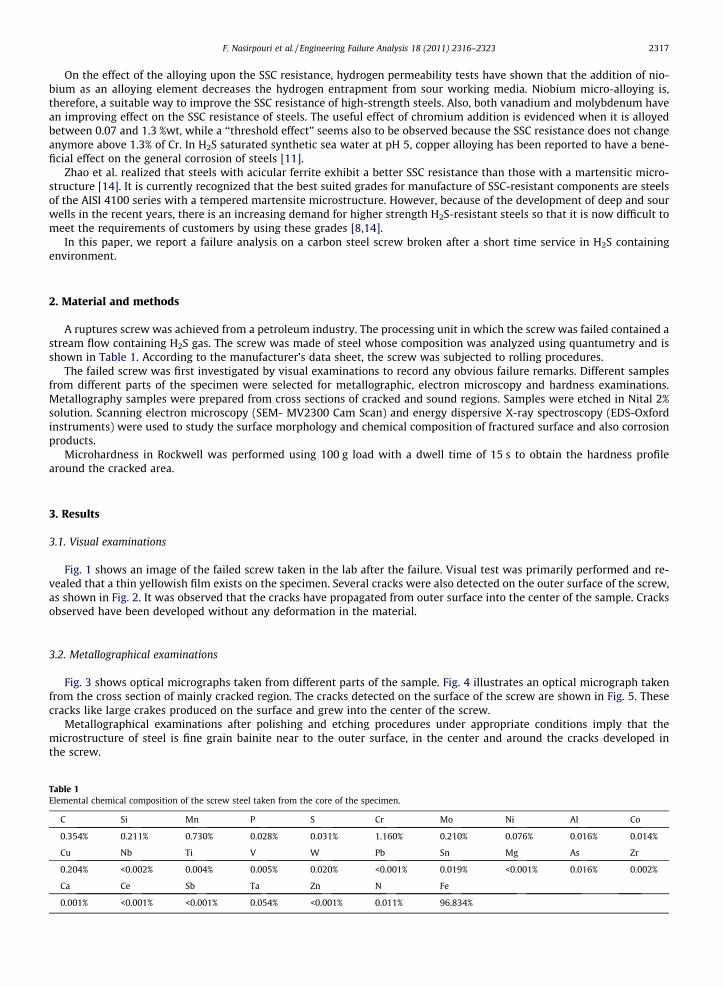
Fig. 1. An image of the failed screw taken in the lab after the failure.
Fig. 2. Images of the fracture surface and cracks and corrosion products formed on the screw from different angles.
2318 F. Nasirpouri et al. / Engineering Failure Analysis 18 (2011) 2316–2323
3.3. Hardness profilometry
Microhardness test was carried out on both sound and cracked regions of the specimen. Profiles of hardness of the metalacross the crack and inside the sound sample are shown in Fig. 6. We observed that hardness is the highest on surface whileit gradually decreases along the propagation line of the crack towards the center of the sample and the crack tip where thehardness is the lowest.
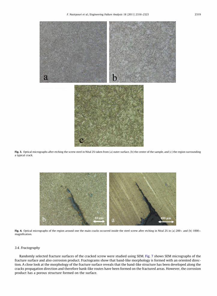
Fig. 3. Optical micrographs after etching the screw steel in Nital 2% taken from (a) outer surface, (b) the center of the sample, and (c) the region surroundinga typical crack.
Fig. 4. Optical micrographs of the region around one the main cracks occurred inside the steel screw after etching in Nital 2% in (a) 200� and (b) 1000�magnification.
F. Nasirpouri et al. / Engineering Failure Analysis 18 (2011) 2316–2323 2319
3.4. Fractography
Randomly selected fracture surfaces of the cracked screw were studied using SEM. Fig. 7 shows SEM micrographs of thefracture surface and also corrosion product. Fractograms show that band-like morphology is formed with an oriented direc-tion. A close look at the morphology of the fracture surface reveals that the band-like structure has been developed along thecracks propagation direction and therefore bank-like routes have been formed on the fractured areas. However, the corrosionproduct has a porous structure formed on the surface.
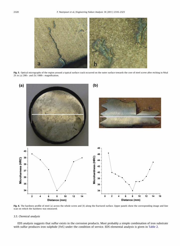
Fig. 5. Optical micrographs of the region around a typical surface crack occurred on the outer surface towards the core of steel screw after etching in Nital2% in (a) 200� and (b) 1000� magnification.
Fig. 6. The hardness profile of steel (a) across the whole screw and (b) along the fractured surface. Upper panels show the corresponding image and linescan on which the hardness was measured.
2320 F. Nasirpouri et al. / Engineering Failure Analysis 18 (2011) 2316–2323
3.5. Chemical analysis
EDS analysis suggests that sulfur exists in the corrosion products. Most probably a simple combination of iron substratewith sulfur produces iron sulphide (FeS) under the condition of service. EDS elemental analysis is given in Table 2.

Fig. 7. SEM images of (a) a typical fracture surface of the screw steel, (b and c) band-like routes for crack growth and (d) of the morphology of the corrosionproduct formed on the surface containing a compound of sulfur.
Table 2EDS elemental analysis of the corrosion product formed on the fracture surface.
Element App Intensity Weight% Weight% Atomic%Conc. Corrn. Sigma
O K 4.32 0.6952 11.02 0.53 26.15S K 11.85 0.7923 26.52 0.30 31.39Fe K 33.13 0.9402 62.46 0.45 42.46
Totals 100.00
F. Nasirpouri et al. / Engineering Failure Analysis 18 (2011) 2316–2323 2321
4. Discussion
In general, four conditions are necessary for SCC to occur: (a) susceptible material, (b) sustained tensile stress, eitherresidual or applied, (c) aggressive environment containing specific ions, i.e., H2S and (d) presence of an electrolyte (water/moisture) [16]. NACE MR0175 standard procedure [17] for materials for use in H2S-containing environments in oil andgas production recommends the standard chemical composition and mechanical properties of the materials for such appli-cation in screws. Under the given conditions predicted by the standard, SSC can significantly be prohibited during serviceunder H2S condition. The ASTM A-320 standard procedure [18] recommends a maximum hardness of 235 HB in steels whichshould be quench-hardened and tempered at a minimum temperature of 620 �C. Once this heat treatment process is con-ducted, ferrite phase forms and becomes dominant, rendering the steel to have a hardness of below 22 HRC (or 235 HB)[17,18].
Metallographic images taken from the material at the core of the screw shows that bainite is detected as the stable phase.This phase generally preserves a high hardness in steels. Microhardness measurements carried out on the central part of the

2322 F. Nasirpouri et al. / Engineering Failure Analysis 18 (2011) 2316–2323
screw farther to the crack exhibit a hardness of value of 34 HRC which exceeds the recommended hardness by the standards,i.e. 22 HRC. Therefore, the material is basically susceptible to various types of brittle fracture under the service.
During service, the steel is exposed to acidic environments containing H2S, which may in turn form atomic hydrogenbeing adsorbed on surface according to the following reactions:
H2Sþ e� ! HS� þHads; ð1Þ
Hads þH2Sþ e� ! HS� þH2; ð2Þ
Hads () Hads; ð3Þ
where Hads and Habs are the adsorbed hydrogen atoms on surface and adsorbed hydrogen atoms in steel, respectively. In factadsorbed hydrogen on surface is a unique source for hydrogen diffusion and accumulation in steel. Increasing H2S in envi-ronment intensifies this effect and more hydrogen atom will diffuse in steel with increasing time during service [3].
On the other hand, another possible reaction takes place as a consequence of direct contact of steel and hydrogensulphide:
H2Sþ Fe! FeSþ 2H: ð4Þ
It is generally expected that when an adhesive FeS crust is formed on the steel surface, further diffusion of atomic hydro-gen is inhibited. However, the FeS crust in humid H2S environment cannot avoid diffusing the hydrogen atoms into the plas-tic zone of crack tip due to a weak strength between crust and background. Therefore, FeS crust dissociates [3].
On the origin of the initiation of crack and its propagation in the screw, crack growth patterns and the fractured surfacesshow important features. Based on our examinations, a major and considerable issue that exists in the material is the dif-ference between the hardness of the region surrounding the crack tip and the surface of steel material. Hardness graduallydecreases from the surface of the steel screw and therefore brittleness increases from crack tip to the surface.
We interpret this evidence with the diffusion of hydrogen atoms from surface into the steel which is accompanied withhydrogen embrittlement. However, an improper pre-heat treatment can probably be another reason for the higher hardnessof the material. EDS analysis shows that the corrosion product on surface is most likely FeS. This brittle phase also is one ofthe destruction reasons.
Fig. 4 shows that how the main crack propagates inside the screw steel. The main crack nucleates from defects and holeson the outer surface as a result of the hydrogen embrittlement and because of stress deformation bands connecting crackedges to each other. Presence of a brittle and porous FeS phase on surface intensifies this process. Small cracks then nucleatein deformation bands (Fig. 7) and join each other. If this process repeats crack will grow towards the center and finally sam-ple is ruptured by stress corrosion.
5. Conclusions and recommendations
Based on the failure analysis given in this investigation it can be concluded that higher hardness of the specimen than theallowed value recommended by NACE MR0175 standard procedure is the main factor causing the failure in the steel screw.An improper pre-heat treatment before service is probably the most reasonable description for the material deficiency. How-ever, the formation of a porous and brittle FeS layer observed by SEM and EDS has caused the hydrogen embrittlement form-ing the cracks to initiate on the surface. It can be suggested that addition of a corrosion inhibitor, gas dehumidification,improving of the steel properties by chemical component, steel making, rolling treatments control, homogenous microstruc-ture, improving weld ability and harden ability may be done to prevent SSC corrosion [3,11].
References
[1] Ramírez E, González-Rodriguez JG, Torres-Islas A, Serna S, Campillo B, Dominguez-Patiño G, et al. Effect of microstructure on the sulphide stresscracking susceptibility of a high strength pipeline steel. Corros Sci 2008;50:3534–41.
[2] Carneiro RA, Ratnapuli RC, de Freitas Cunha Lins V. The influence of chemical composition and microstructure of API line pipe steels on hydrogeninduced cracking and sulfide stress corrosion cracking. Mater Sci Eng, A 2003;357:104–10.
[3] Damage mechanisms affecting fixed equipment in the refining industry. American Petroleum Institute. API 571 RP; 2003. p. 5.41–5.44.[4] Klyk-Spyra K, Sozanska M. Quantitative fractography of 2205 duplex stainless steel after a sulfide stress cracking test. Mater Charact 2006;56:384–8.[5] Zheng CB, Huang YL, Yu Q, Huo CY. Effect of H2S on stress corrosion cracking and hydrogen permeation behaviour of X56 grade steel in atmospheric
environment. Corros Eng Sci Technol 2009;44:96–100.[6] Elboujdaini M, Revie RW. Metallurgical factors in stress corrosion cracking (SCC) and hydrogen-induced cracking (HIC). J Solid State Electrochem
2009;13:1091–9.[7] Huang F, Li XG, Liu J, Qu YM, Jia J, Du CW. Hydrogen-induced cracking susceptibility and hydrogen trapping efficiency of different microstructure X80
pipeline steel. J Mater Sci 2011;46:715–22.[8] Swieczko-Zurek B, Zielinski A, Lunarska E. Hydrogen degradation of structural steels in technical hydrocarbon liquids. Mater Corros 2008;59:289–95.[9] Albarran JL, Martinez L, Lopez HF. Effect of heat treatment on the stress corrosion resistance of a microalloyed pipeline steel. Corros Sci
1999;41:1037–49.[10] Barbosa C, de Souza SMC, Centeno RO, Abud IC, Ferraz OB. Failure analysis of pipes used in a hydrodesulfuration system of a petrochemical plant. Eng
Fail Anal 2006;13:1076–91.[11] Mendibide C, Sourmail T. Composition optimization of high-strength steels for sulfide stress cracking resistance improvement. Corros Sci
2009;51:2878–84.

F. Nasirpouri et al. / Engineering Failure Analysis 18 (2011) 2316–2323 2323
[12] Lucio-Garcia MA, Gonzalez-Rodriguez JG, Casales M, Martinez L, Chacon-Nava JG, Neri-Flores MA, et al. Effect of heat treatment on H2S corrosion of amicro-alloyed C–Mn steel. Corros Sci 2009;51:2380–6.
[13] Methods and controls to prevent in-service environmental cracking of carbon steel weldments in corrosive petroleum refining environments, NACEstandard RP0472-2000. Item no. 21006.
[14] Zhao Ming-Chun, Liu Ming, Atrens Andrej, Shan Yi-Yin, Yang Ke. Effect of applied stress and microstructure on sulfide stress cracking resistance ofpipeline steels subject to hydrogen sulfide. Mater Sci Eng 2008;A 478:43–7.
[15] Azevedo Cesar RF. Eng Fail Anal 2007;14:978–94.[16] Wang Y, Lu Ye-Bo, Pan Hong-Liang. Failure analysis of a hydro-processing reactor. Eng Fail Anal 2009;16:11–8.[17] Petroleum and natural gas industries materials for use in H2S containing environments in oil and gas production. NACE MR0175/ ISO 15156-1. Item
no. 21306.[18] Standard specification for alloy steel bolting materials for low-temperature service. ASTM A 320/A 320M.