Fundamentals of Geometric Dimensioning & Tolerancing - Not ...
Upload
phungkhanhCategory
view
228download
2
AMT Certification Program - Study Guide
September 2013 (S.G. 09.13) Page 1 (Drawing/Geometric Tolerancing) Chapter 8
CHAPTER
ENGINEERING DRAWINGS & GEOMETRIC TOLERANCING
8.1 Introduction 8.2 Glossary 8.3 Understanding Engineering Drawings 8.4 Understanding Geometric Dimensioning & Tolerancing 8.5 Surface Finish & Texture 8.6 Review Questions
8.1 Introduction One of the major instruments in the revival of US manufacturing has been the dominant role of computers in all aspects of manufacturing. The use of computers or CAD, (Computer Aided Design) in product engineering permitted design optimization, rapid design changes, swift modification of complex assemblies and preparation of the engineering bill of material with required drawings through the use of a pen under the command of a computer. In a similar fashion, the same computer can be used to generate manufacturing CNC part programs permitting CNC machine tools to utilize the CAD output in actual part piece production. The linking of these two functions is correctly called CAD/CAM. Companies that use CAD/CAM can produce superior products faster and modify such output to meet rapidly changing market conditions. The output of the CAD/CAM revolution is still Engineering Drawings, either on paper or on a computer. The machine tool sales engineer must be in a position to read,
8
AMT Certification Program - Study Guide
September 2013 (S.G. 09.13) Page 2 (Drawing/Geometric Tolerancing) Chapter 8
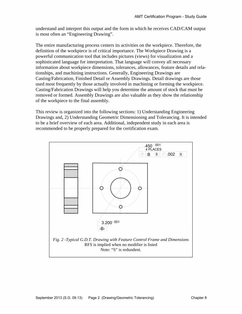
understand and interpret this output and the form in which he receives CAD/CAM output is most often an “Engineering Drawing”. The entire manufacturing process centers its activities on the workpiece. Therefore, the definition of the workpiece is of critical importance. The Workpiece Drawing is a powerful communication tool that includes pictures (views) for visualization and a sophisticated language for interpretation. That language will convey all necessary information about workpiece dimensions, tolerances, allowances, feature details and rela-tionships, and machining instructions. Generally, Engineering Drawings are Casting/Fabrication, Finished Detail or Assembly Drawings. Detail drawings are those used most frequently by those actually involved in machining or forming the workpiece. Casting/Fabrication Drawings will help you determine the amount of stock that must be removed or formed. Assembly Drawings are also valuable as they show the relationship of the workpiece to the final assembly. This review is organized into the following sections: 1) Understanding Engineering Drawings and, 2) Understanding Geometric Dimensioning and Tolerancing. It is intended to be a brief overview of each area. Additional, independent study in each area is recommended to be properly prepared for the certification exam.
3.200-B-
001
B
001.450
.002S S4 PLACES
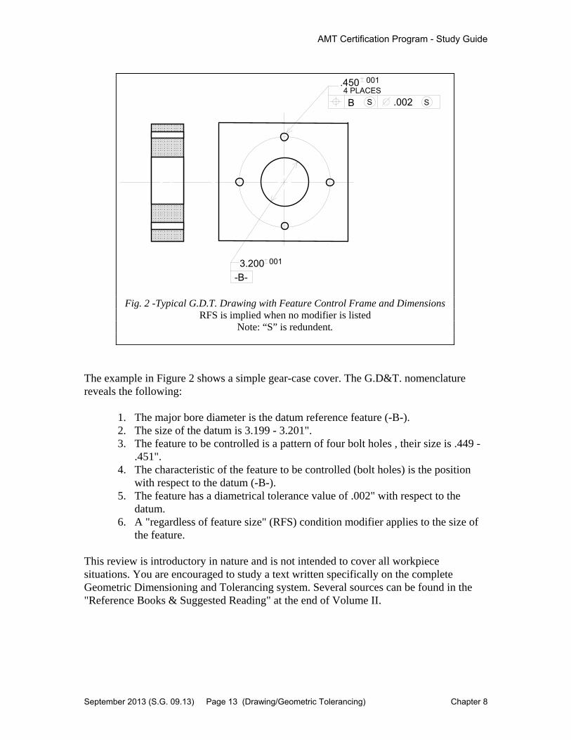
Fig. 2 -Typical G.D.T. Drawing with Feature Control Frame and Dimensions RFS is implied when no modifier is listed
Note: “S” is redundent.

AMT Certification Program - Study Guide
September 2013 (S.G. 09.13) Page 3 (Drawing/Geometric Tolerancing) Chapter 8
8.2 GD&T Glossary
Actual Local Size - The value of any individual distance at any cross section of a feature of size.
Angularity - The condition of a surface, centerplane or axis being exactly at a specified angle
ASME Y14.5M-1994 - The national standard for dimensioning and tolerancing in the United States. ASME stands for American Society of Mechanical Engineers. The Y14.5 is the standard number. "M" is to indicate the standard is metric, and 1994 is the date the standard was officially approved.
Basic Dimension - A numerical value used to describe the theoretically exact size, true profile, orientation, or location of a feature or datum target.
Bilateral Tolerance - A tolerance that allows the dimension to vary in both the plus and minus directions, ex: +/- .005 “
Circularity - A condition where all points of a surface of revolution, at any section perpendicular to a common axis, are equidistant from that axis.
Circular Runout - A composite control that affects the form, orientation, and location of circular elements of a part feature relative to a datum axis.
Coaxial Diameters - Two (or more) diameters that are shown on the drawing as being on the same centerline (axis).
Concentricity - The condition where the median points of all diametrically opposed elements of a cylinder (or a surface of revolution) are congruent with the axis of a datum feature.
Cylindricity - A condition of a surface of revolution in which all points of the surface are equidistant from a common axis.
Datum - A theoretically exact plane, point or axis from which a dimensional measurement is made.

AMT Certification Program - Study Guide
September 2013 (S.G. 09.13) Page 4 (Drawing/Geometric Tolerancing) Chapter 8
Datum Feature - A part feature that contacts a datum.
Datum Feature Simulator - The inspection equipment (or gage surfaces) used to establish a datum.
Datum Reference Frame - A set of three mutually perpendicular datum planes.
Dimension - A numerical value expressed in appropriate units of measure and used to define the size, location, orientation, form, or other geometric characteristics of a part.
Engineering Drawing - A document that communicates a precise description of a part. This description consists of pictures, words, numbers, and symbols.
Feature - A general term applied to a physical portion of a part, such as a surface, hole, or slot.
Feature Control Frame - A rectangular box that is divided into compartments within which the geometric characteristic symbol, tolerance value, modifiers, and datum references are placed.
Flatness - The condition of a surface having all of its elements in one plane.
Geometric Characteristic Symbols (14) - The symbols are divided into five categories: form, profile, orientation, location, and runout.
Geometric Dimensioning and Tolerancing (GD&T) - A set of fourteen symbols used in the language of GD&T. It consists of well-defined of symbols, rules, definitions and conventions, used on Engineering Drawings to accurately describe a part. GD&T is a precise mathematical language that can be used to describe the size, form, orientation, and location of part features. GD&T is also a design philosophy on how to design and dimension parts.
International Standards Organization (ISO) - The organization that published an associated series of standards on dimensioning and tolerancing.
Least Material Condition - The condition in which a feature of size contains the least amount of material everywhere within the stated limits of size.
Limit Tolerance - When a dimension has its high and low limits stated. In a limit tolerance, the high value is placed on top, and the low value is placed on the bottom.
Maximum Material Condition - The condition in which a feature of size contains the maximum amount of material everywhere within the stated limits of size.

AMT Certification Program - Study Guide
September 2013 (S.G. 09.13) Page 5 (Drawing/Geometric Tolerancing) Chapter 8
Parallelism - The condition that results when a surface, axis or centerplane is exactly parallel to a datum.
Perpendicularity - The condition that results when a surface, axis, or centerplane is exactly 90° to a datum.
Profile- The outline of a part feature in a given plane.
Profile Control - A geometric tolerance that specifies a uniform boundary along the true profile that the elements of the surface must lie within.
Profile of a Line Control - A geometric tolerance that limits the amount of error for line elements relative to their true profile.
Profile of a Surface Control - A geometric tolerance that limits the amount of error a surface can have relative to its true profile.
Projected Tolerance Zone - In GD&T, a zone specified for a given height above a hole in which a pin, cap, screw, bolt, etc., is to be installed. The zone provides a cylindrical area in which the feature must lie. It controls the perpendicularity of the hole to prevent interference with the mating part.
Regardless of Feature Size - The term that indicates a geometric tolerance applies at any increment of size of the feature, within its size tolerance. If a modifier is not specified, then RFS is used by default.
Straightness (Axis or Centerplane) - The condition where an axis is a straight line (or, in the case of a centerplane, each line element is a straight line).
Symmetry - The condition where the median points of all opposed elements of two or more feature surfaces are congruent with the axis or centerplane of a datum feature.
Tertiary Datum - The third datum plane that the part contacts in a dimensional measurement.
Tolerance - The total amount that features of the part are permitted to vary from the specified dimension.
Tolerance Stack - A calculation used to find the extreme maximum / minimum distance on a part.

AMT Certification Program - Study Guide
September 2013 (S.G. 09.13) Page 6 (Drawing/Geometric Tolerancing) Chapter 8
Total Runout - A composite control affecting the form, orientation, and location of all surface elements ofa diameter (or surface) relative to a datum axis. Also known as, (T.I.R total indicator reading)
True Position - The theoretically exact location of a feature of size as defined by basic dimensions.
Taken from Effective Training, inc. Author- Alex Krulikowski
AMT Certification Program - Study Guide
September 2013 (S.G. 09.13) Page 7 (Drawing/Geometric Tolerancing) Chapter 8
8.3 Understanding Engineering Drawings
The Engineering Drawing is primarily the formal communication tool between the designer and the manufacturing/assembly process. However, there are many other functions within a company that will utilize the Drawing. Among those are purchasing, which may use the print to obtain raw materials or obtain quotations on equipment to produce the workpiece. As a machine tool sales engineer, your ability to read the workpiece drawings properly can help you determine the proper process and machines to do the job. This may be your biggest competitive advantage. Be sure to obtain all necessary Drawings that apply to the workpiece and the finished assembly (rough casting or fabrication, machined and assembly). Ask your customer for both rough unmachined and finished machine part samples. The Engineering Drawing contains four basic parts: 1) body, 2) title block, 3) revision's list and 4) materials list. In addition to the body (views and dimensions), careful attention should be paid to the Revisions and Material lists. The Revisions list will tell you if you are working with the most up-to-date Workpiece Drawing. Always indicate on your proposal the latest workpiece revision if your proposal was based upon the drawing (e.g., a workpiece time study or recommended process of machining). Also, the materials list will indicate the workpiece material characteristics. These are important in determining the machinability of the part. The body of the drawing includes views and dimensions. The most common views used in the detail drawing are the Front, Top and Side views. When required, special views such as sections and auxiliary, usually projections, may be present. Dimensions on the Drawing determine the size and location of surfaces and features and fall into one of the following categories:
1. Linear - straight-line distance 2. Angular - an angle or length of an arc 3. Radial - size of a radius 4. Tabular - shown in chart format 5. Coordinate - dimension to a reference point (common on manufacturing
drawings)
The dimensions on a drawing also indicate the tolerance (range of size) and allowance (minimum allowable difference in size of mating parts).
AMT Certification Program - Study Guide
September 2013 (S.G. 09.13) Page 8 (Drawing/Geometric Tolerancing) Chapter 8
8.4 Understanding Geometric
Dimensioning & Tolerancing
ASME Y14.5M-1994 - The national standard for dimensioning and tolerancing in the United States. ASME stands for American Society of Mechanical Engineers. The Y14.5 is the standard number. "M" is to indicate the standard is metric, and 1994 is the date the standard was officially approved.
1. A universal, international system of dimensioning and tolerancing. 2. A simplified, easy-to-read symbolic system. 3. Reduced interpretation time yielding increased shop productivity. 4. Improved workpiece feature location and definition (esp. holes). 5. Increased workpiece and finished assembly fit for better product quality.
The major advantages of GD&T are improved product quality and reduced shop time. Any increase in dimensional or form accuracy reduces tolerance buildup in the overall assembly. Therefore, the quality of the finished assembly is enhanced. For example, in a gearbox assembly the alignment of mating surfaces as well as location and concentricity of bearing bores directly affects final gear shaft alignment and location. These factors can alter gear center-to-center distances that affect noise, life and gear train efficiency.
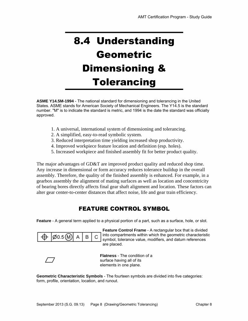
FEATURE CONTROL SYMBOL
Feature - A general term applied to a physical portion of a part, such as a surface, hole, or slot.
Feature Control Frame - A rectangular box that is divided into compartments within which the geometric characteristic symbol, tolerance value, modifiers, and datum references are placed.
Flatness - The condition of a surface having all of its elements in one plane.
Geometric Characteristic Symbols - The fourteen symbols are divided into five categories: form, profile, orientation, location, and runout.

AMT Certification Program - Study Guide
September 2013 (S.G. 09.13) Page 9 (Drawing/Geometric Tolerancing) Chapter 8
Geometric Dimensioning and Tolerancing (GD&T) - The fourteen GD&T symbols used on Engineering Drawings consists of well-defined symbols, rules, definitions and conventions that accurately describe a part. GD&T is a precise mathematical language. They describe the size, form, orientation, and location of part features. GD&T is also a design philosophy on how to design and dimension parts.
International Standards Organization (ISO) - The organization that published an associated series of standards on dimensioning and tolerancing.
GEOMETRIC CHARACTERISTIC SYMBOLS AND DATUMS
Geometric characteristic symbols indicate the part characteristic that are to be controlled. Symbols are different and specify geometric characteristics, dimensional requirements, and application. The common symbols are listed below (definitions can be found in the glossary). The symbols are divided into five categories: form, profile, orientation, location, and runout.
Features Group Characteristic Symbol
For individual features
Form
Straightness
Flatness
Circulatity (roundness)
Cylindricity
For individual or related features
Profile Profile of a line
Profile of a surface
For related features
Orientation
Angularity
Perpendicularity
Parallelism
Location
Position
Concentricity/Coaxiality

AMT Certification Program - Study Guide
September 2013 (S.G. 09.13) Page 10 (Drawing/Geometric Tolerancing) Chapter 8
Symmetry
Runout
Circular Runout
Total Runout
Datum - A theoretically exact plane, point or axis from which a dimensional measurement is made.
Datum Feature - A part feature that contacts a datum.
Datum Feature Simulator - The inspection equipment (or gage surfaces) used to establish a datum.
Datum Reference Frame - A set of three mutually perpendicular datum planes.
Dimension - A numerical value expressed in appropriate units of measure and used to define the size, location, orientation, form, or other geometric characteristics of a part.
Engineering Drawing - A document that communicates a precise description of a part. This description consists of pictures, words, numbers, and symbols.
Feature - A general term applied to a physical portion of a part, such as a surface, hole, or slot.
Feature Control Frame - A rectangular box that is divided into compartments within which the geometric characteristic symbol, tolerance value, modifiers, and datum references are placed.
Flatness - The condition of a surface having all of its elements in one plane.
Geometric Characteristic Symbols - The fourteen symbols are divided into five categories: form, profile, orientation, location, and runout.
Geometric Dimensioning and Tolerancing (GD&T) - The fourteen GD&T symbols used on Engineering Drawings consists of well-defined symbols, rules, definitions and conventions that accurately describe a part. GD&T is a precise mathematical language. They describe the size, form, orientation, and location of part features. GD&T is also a design philosophy on how to design and dimension parts.
International Standards Organization (ISO) - The organization that published an associated series of standards on dimensioning and tolerancing.

AMT Certification Program - Study Guide
September 2013 (S.G. 09.13) Page 11 (Drawing/Geometric Tolerancing) Chapter 8
Least Material Condition - The condition in which a feature of size contains the least amount of material everywhere within the stated limits of size.
Limit Tolerance - When a dimension has its high and low limits stated. In a limit tolerance, the high value is placed on top, and the low value is placed on the bottom.
Maximum Material Condition - The condition in which a feature of size contains the maximum amount of material everywhere within the stated limits of size.
Parallelism - The condition that results when a surface, axis or centerplane is exactly parallel to a datum.
Perpendicularity - The condition that results when a surface, axis, or centerplane is exactly 90° to a datum.
Profile- The outline of a part feature in a given plane.
Profile Control - A geometric tolerance that specifies a uniform boundary along the true profile that the elements of the surface must lie within.
Profile of a Line Control - A geometric tolerance that limits the amount of error for line elements relative to their true profile.
Profile of a Surface Control - A geometric tolerance that limits the amount of error a surface can have relative to its true profile.
Projected Tolerance Zone - A tolerance zone that is projected above the part surface.
Regardless of Feature Size - The term that indicates a geometric tolerance applies at any increment of size of the feature, within its size tolerance.
Straightness (Axis or Centerplane) - The condition where an axis is a straight line (or, in the case of a centerplane, each line element is a straight line).
AMT Certification Program - Study Guide
September 2013 (S.G. 09.13) Page 12 (Drawing/Geometric Tolerancing) Chapter 8
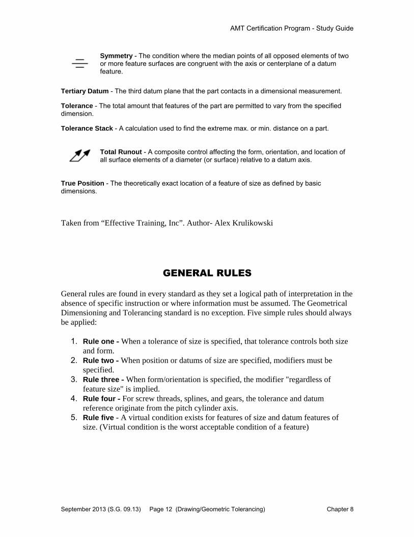
Symmetry - The condition where the median points of all opposed elements of two or more feature surfaces are congruent with the axis or centerplane of a datum feature.
Tertiary Datum - The third datum plane that the part contacts in a dimensional measurement.
Tolerance - The total amount that features of the part are permitted to vary from the specified dimension.
Tolerance Stack - A calculation used to find the extreme max. or min. distance on a part.
Total Runout - A composite control affecting the form, orientation, and location of all surface elements of a diameter (or surface) relative to a datum axis.
True Position - The theoretically exact location of a feature of size as defined by basic dimensions.
Taken from “Effective Training, Inc”. Author- Alex Krulikowski
GENERAL RULES General rules are found in every standard as they set a logical path of interpretation in the absence of specific instruction or where information must be assumed. The Geometrical Dimensioning and Tolerancing standard is no exception. Five simple rules should always be applied:
1. Rule one - When a tolerance of size is specified, that tolerance controls both size and form.
2. Rule two - When position or datums of size are specified, modifiers must be specified.
3. Rule three - When form/orientation is specified, the modifier "regardless of feature size" is implied.
4. Rule four - For screw threads, splines, and gears, the tolerance and datum reference originate from the pitch cylinder axis.
5. Rule five - A virtual condition exists for features of size and datum features of size. (Virtual condition is the worst acceptable condition of a feature)
AMT Certification Program - Study Guide
September 2013 (S.G. 09.13) Page 13 (Drawing/Geometric Tolerancing) Chapter 8
The example in Figure 2 shows a simple gear-case cover. The G.D&T. nomenclature reveals the following:
1. The major bore diameter is the datum reference feature (-B-). 2. The size of the datum is 3.199 - 3.201". 3. The feature to be controlled is a pattern of four bolt holes , their size is .449 -
.451". 4. The characteristic of the feature to be controlled (bolt holes) is the position
with respect to the datum (-B-). 5. The feature has a diametrical tolerance value of .002" with respect to the
datum. 6. A "regardless of feature size" (RFS) condition modifier applies to the size of
the feature. This review is introductory in nature and is not intended to cover all workpiece situations. You are encouraged to study a text written specifically on the complete Geometric Dimensioning and Tolerancing system. Several sources can be found in the "Reference Books & Suggested Reading" at the end of Volume II.
3.200-B-
001
B
001.450
.002S S4 PLACES
Fig. 2 -Typical G.D.T. Drawing with Feature Control Frame and Dimensions RFS is implied when no modifier is listed
Note: “S” is redundent.
AMT Certification Program - Study Guide
September 2013 (S.G. 09.13) Page 14 (Drawing/Geometric Tolerancing) Chapter 8
8.5 Surface Finish & Texture
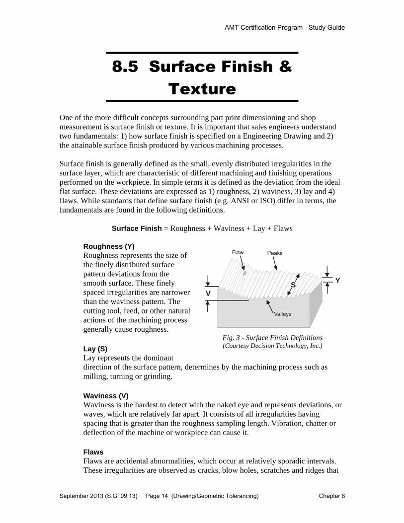
One of the more difficult concepts surrounding part print dimensioning and shop measurement is surface finish or texture. It is important that sales engineers understand two fundamentals: 1) how surface finish is specified on a Engineering Drawing and 2) the attainable surface finish produced by various machining processes. Surface finish is generally defined as the small, evenly distributed irregularities in the surface layer, which are characteristic of different machining and finishing operations performed on the workpiece. In simple terms it is defined as the deviation from the ideal flat surface. These deviations are expressed as 1) roughness, 2) waviness, 3) lay and 4) flaws. While standards that define surface finish (e.g. ANSI or ISO) differ in terms, the fundamentals are found in the following definitions.
Surface Finish = Roughness + Waviness + Lay + Flaws Roughness (Y) Roughness represents the size of the finely distributed surface pattern deviations from the smooth surface. These finely spaced irregularities are narrower than the waviness pattern. The cutting tool, feed, or other natural actions of the machining process generally cause roughness.
Lay (S) Lay represents the dominant direction of the surface pattern, determines by the machining process such as milling, turning or grinding.
Waviness (V) Waviness is the hardest to detect with the naked eye and represents deviations, or waves, which are relatively far apart. It consists of all irregularities having spacing that is greater than the roughness sampling length. Vibration, chatter or deflection of the machine or workpiece can cause it.
Flaws Flaws are accidental abnormalities, which occur at relatively sporadic intervals. These irregularities are observed as cracks, blow holes, scratches and ridges that
Y
VS
Peaks
Valleys
Flaw
Fig. 3 - Surface Finish Definitions (Courtesy Decision Technology, Inc.)

AMT Certification Program - Study Guide
September 2013 (S.G. 09.13) Page 15 (Drawing/Geometric Tolerancing) Chapter 8
do not follow a regular pattern. Flaws are generally not included in the measurement of average roughness.
Figure 4 shows cross-sections of surfaces having greatly different surface finish characteristics. However, all of the surfaces have approximately the same “roughness” value (Ra). This demonstrates the importance of not relying solely on the “roughness” value when specifying surface finish. Some machinists can drag their fingernail across a machined surface and announce the roughness value with a surprising degree of accuracy. This manual, “roughness only” technique may work when the parts are being produced from a repeatable process, such as milling or turning. However, it is highly doubtful that a machinist would guess the same roughness value for all the examples shown in Figure 4.
Understanding surface finish requirements on customer’s part prints can be challenging. It is imperative that the sales engineer pay attention to several important issues: 1) the end application of the workpiece, 2) the machining process and 3) the standards used to define the symbols on the drawing.
Workpiece Application Product design engineers specify different workpiece finishes based on how the part will be used in its final application and its expected life. For example, surfaces finish applications could be for: 1) appearance, 2) mating surfaces bolted together, 3) gasketed surfaces, 4) bearing and wear surfaces, 5) friction, etc. Other factors are corrosion, lubricant distribution, seating or sealing capacity and electrical conductivity. Cost considerations are also a part of surface finish design. Attaining some surface finish requirements may dictate additional machining operations (e.g. grinding, honing, etc.), which add significant cost. In other applications, having surface finish specifications set too high, may be adding unnecessary cost. The extent of roughness, lay and waviness will affect each application differently. While the machining process can cause all three, waviness is more prone to the effects of heat treatment, cutting tool runout, chatter, vibration and deflection of the machine and workpiece. It should not be assumed that all surfaces should be as flat and smooth as possible. Any number of applications, such as gasketed surfaces, depends on a certain amount of roughness for holding and sealing.
A
B
C
D
Fig. 4 - Surface Finish Examples (Source: Machinability Data Center)

AMT Certification Program - Study Guide
September 2013 (S.G. 09.13) Page 16 (Drawing/Geometric Tolerancing) Chapter 8
Machining Process Each machining process will leave its own distinctive surface finish characteristics. In many cases, simply looking at the surface will reveal the machining processed used. As a general rule, broaching and drilling will leave a very poor surface finish while grinding or lapping would have the best. Milling and turning can vary widely based on process variables and tooling application. The sales engineer should study the chart below to gain an understanding of the various metalcutting processes and the expected surface finish results.
Note: One microinch = one-millionth of an inch (0.000,001 in.) Surface Finish Standards In the past, it was common to find the letters “f” for “finish” and ‘g” for “grind” on the part print. However, these designations no longer meet the rigorous requirements of modern manufacturing. In 1978 and standard was introduced which cleared up the vagueness and inaccuracies of specifying surface finish. The American Society of Mechanical Engineers (ASME) published the standard, ANSI-B 46.1-1978. There are now multiple global standards that define surface finish symbols on part prints. These standards differ in their use of symbols and symbol definitions. There are two ASME standards (B46.1-1995 and Y14.36M-1996), eleven ISO standards as well as Japanese (JIS) and European (DIN) standards that could apply to the interpretation of surface finish and texture. Symbols on older prints are interpreted differently than those on newer prints due to the change in standards. ASME standards have undergone several major revisions since 1968. Unfortunately, there are limited resources to allow
DrillingEDM
MillingBroachingReaming
Boring, TurningElectrolytic Grinding
Roller BurnishingGrinding
HoningPolishingLapping
Super Finishing
1000 500 250 125 63 32 16 8 4 2 1 0.5
Average Roughness, R - MicroinchesaNormalPossible
.

AMT Certification Program - Study Guide
September 2013 (S.G. 09.13) Page 17 (Drawing/Geometric Tolerancing) Chapter 8
translation or correlation between the symbols and parameters found in the different standards. Here is a helpful correlation chart.
Parameters Defined in ASME B.1-1995 Corresponding Parameters in ISO 4287-1997
Ra Arithmetic Average Deviation of the Assessed Profile Ra Rq Root Mean Square Deviation of the Assessed Profile Rq Rp Maximum Profile Peak Height --- Rv Maximum Profile Valley Depth --- Rt Maximum Height of the Profile Rt Rpm Average Maximum Profile Peak Height --- Rz Average Maximum Height of the Profile Ry Rmax Maximum Roughness Depth --- Sm Mean Spacing of Profile Irregularities Rsm Pc Peak Density --- Wt Waviness Height Wt Rsk Skewness Rsk
Surface Finish Symbols The surface finish symbol is a checkmark with a horizontal line. If “roughness” is the only parameter specified, the horizontal line can be omitted. Figure 6 illustrates where the various surface finish parameters will be found with the checkmark. Filling the checkmark with dimensions and other symbols is the correct way to fully specify surface finish. The parameters are shown below. In addition, a triangle located in the “v” of the checkmark indicates a machining allowance requirement. A small circle in the “v” prohibits the removal of any material.
A = Roughness height average or maximum-minimum roughness height average.
B = Machining allowance C = Waviness and waviness spacing D = Roughness sampling length E = Lay
A
B
C
DE
Fig. 6 - Surface Symbol
63
.002-2
.100
Waviness Height
Roughness Height(Arithmetical Average)
Waviness Spacing
Roughness Sampling Length
Lay
Fig. 7 – Typical Surface Symbol (Source: Machinability Data Center)

AMT Certification Program - Study Guide
September 2013 (S.G. 09.13) Page 18 (Drawing/Geometric Tolerancing) Chapter 8
Frequently, leader lines are used with the checkmark to point to the indicated surface. Where the symbol is used with a dimension, it will affect the entire surface identified by the symbol. A typical example is presented in Figure 8.
Measurement Methods There are a number of methods used to measure surface finish. Roughness can be measured with several common devices: 1) surface finish gage, 2) Profilometer, 3) visual comparator, etc. Waviness and lay are harder to measure. They will require expensive probe-based systems or laser measurement devices.
Unless otherwise specified all surfaces 32
16
xx DIA 16
0.010
Fig. 8 - Surface Finish Symbols (Source: Adapted from Sheffield Measurement)

AMT Certification Program - Study Guide
September 2013 (S.G. 09.13) Page 19 (Drawing/Geometric Tolerancing) Chapter 8
8.6 Review Questions
These review questions are provided for study purposes only and are not on the CMTSE certification exam. Correctly answering these questions does not guarantee a passing exam grade.
1. Finished Detail drawings are generally not useful for: 1. workpiece sizes and tolerances. 2. the material composition of the workpiece. 3. determining the machining process of the workpiece. 4. determining casting or fabrication information. 2. The symbol / / stands for: 1. straightness. 2. angularity. 3. parallelism. 4. flatness. QUESTION 3 REFERS TO THE FOLLOWING DIAGRAM
.020
3. How would you interpret the above diagram? 1. All bored holes are to be round within +/-0.010" 2. This is a true position tolerance location, to be held within 0.020" 3. The location tolerance is within +0.010" -0.010" of cylinder opening 4. The front face of a cylindrical opening is to be flat within 0.020" 4. Where on the Drawing would you expect to find the nomenclature 1010 Steel as
referring to the workpiece? 1. The materials list 2. The body 3. The revisions list 4. The title block 5. On a drawing, a dimension that is underlined would usually indicate a dimension
that is: 1. standard. 2. not drawn to scale. 3. the reference. 4. approximate.

AMT Certification Program - Study Guide
September 2013 (S.G. 09.13) Page 20 (Drawing/Geometric Tolerancing) Chapter 8
6. T.I.R. stands for: 1. tolerance in roundness. 2. total included radius. 3. true indicated roundness. 4. total indicator reading.
7. The symbol represents: 1. cylindricity. 2. concentricity. 3. circular runout. 4. roundness. 8. This GDT symbol _|_ represents: 1. straightness. 2. perpendicularity. 3. angularity. 4. parallelism. 9. The initials MMC when found in the feature control frame stands for: 1. mandatory method calibration. 2. maximum material condition. 3. minimum machine clearance. 4. multiple material condition. 10. When a tolerance of size is the only reference given the tolerance controls: 1. size only. 2. size and form. 3. size and orientation. 4. size, form, and position. 11. A Datum supplies the information needed for: 1. correct symbols and attachments. 2. appropriate feature orientation. 3. material identification. 4. clearance between mating parts. 12. Geometric dimensioning and tolerancing is superior to notes for defining a part's
characteristics primarily because: 1. drawing symbols is easy. 2. symbols are convenient to use. 3. notes sometimes need language translation. 4. the meaning of symbols is consistent.

AMT Certification Program - Study Guide
September 2013 (S.G. 09.13) Page 21 (Drawing/Geometric Tolerancing) Chapter 8
13. Which of the following is not a component of formal surface finish definition? 1. Waviness 2. Lay 3. Vibration 4. Roughness
AMT Certification Program - Study Guide
September 2013 (S.G. 09.13) Page 22 (Drawing/Geometric Tolerancing) Chapter 8
ANSWERS TO REVIEW QUESTIONS 1. (4) 2. (3) 3. (2) 4. (1) 5. (2) 6. (4) 7. (2) 8. (2) 9. (2) 10. (2) 11. (2) 12. (4) 13. (3)