ENGINEERING DRAWING - Studiestoday · 2018-11-23 · Draw the isometric projection of the solids,...
28
408 ENGINEERING DRAWING Time allowed : 3 hours Maximum Marks : 70 Note : (i) Attempt all the questions. (ii) Use both sides of the drawing sheet, if necessary. (iii) All dimensions are in millimeters. (iv) Missing and mismatching dimensions, if any, may be suitably assumed. (v) Follow the SP : 46-1988 codes (with First Angle method of projection). (vi) In no view of questions 1 and in no sectioned view of question 3, are hidden edges / lines required. QUESTION PAPER CODE 68/1 1. (a) Construct an isometric scale, 90 mm long. 4 (b) Construct the isometric projection, to isometric scale, of a pentagonal pyramid (base edge = 40 mm and height = 90 mm), keeping it in the inverted position. The axis is perpendicular to H.P. One of its base edges is parallel to V.P. and away from that. Draw the axis and indicate the direction of viewing. Give all dimensions. 8 (c) A cone (diameter = 40 mm and height = 60 mm) is placed, centrally, with its base on the hexagonal face of a hexagonal prism (base edge = 40 mm and height = 25 mm). The common axis is perpendicular to H.P. The base of the prism is on H.P., and one of the base edges is perpendicular to V.P. Draw the isometric projection of the solids, placed together, to isometric scale. Draw the common axis and indicate the direction of viewing. Give all dimensions. 13 Downloaded from www.studiestoday.com Downloaded from www.studiestoday.com
Transcript of ENGINEERING DRAWING - Studiestoday · 2018-11-23 · Draw the isometric projection of the solids,...
408
ENGINEERING DRAWING
Time allowed : 3 hours Maximum Marks : 70
Note :
(i) Attempt all the questions.
(ii) Use both sides of the drawing sheet, if necessary.
(iii) All dimensions are in millimeters.
(iv) Missing and mismatching dimensions, if any, may be suitably assumed.
(v) Follow the SP : 46-1988 codes
(with First Angle method of projection).
(vi) In no view of questions 1 and in no sectioned view of question 3, are hidden
edges / lines required.
QUESTION PAPER CODE 68/1
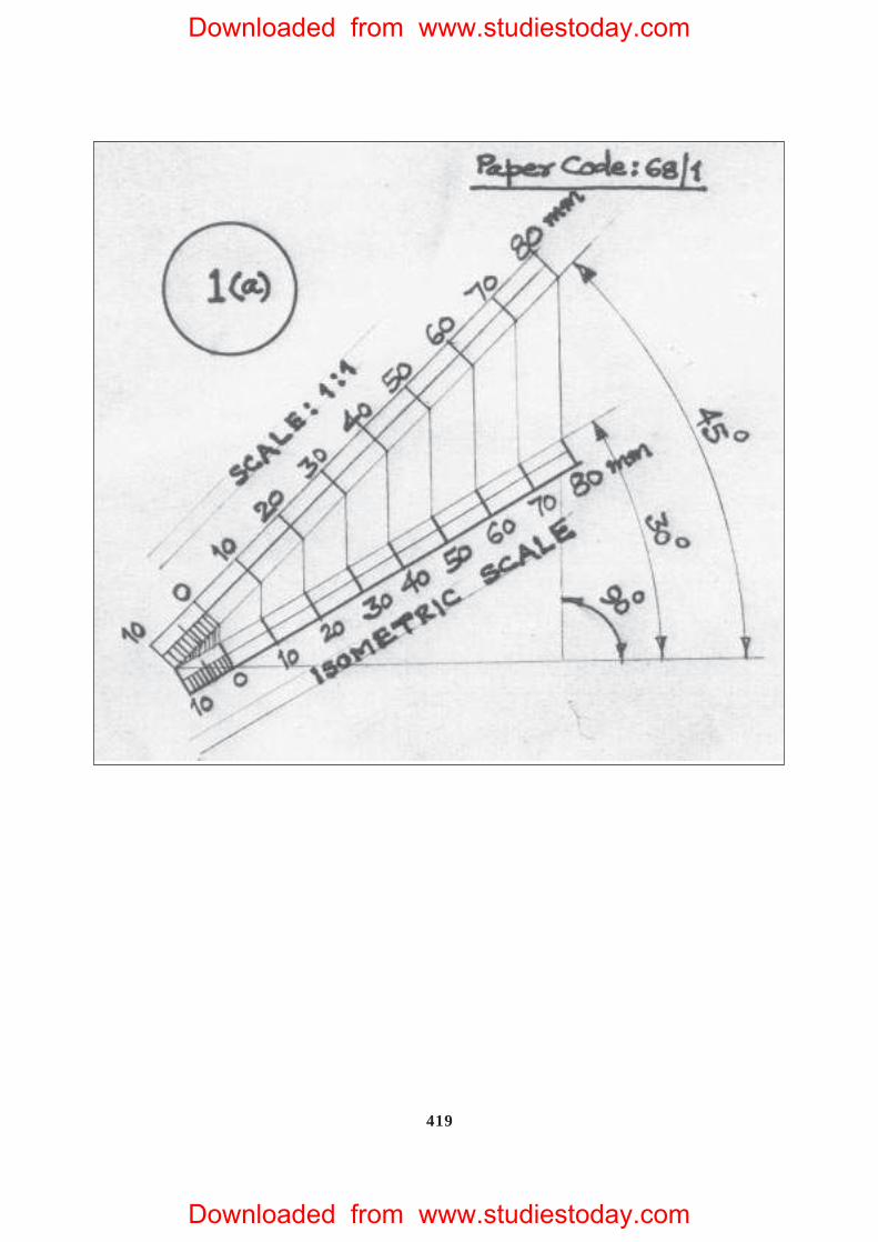
1. (a) Construct an isometric scale, 90 mm long. 4
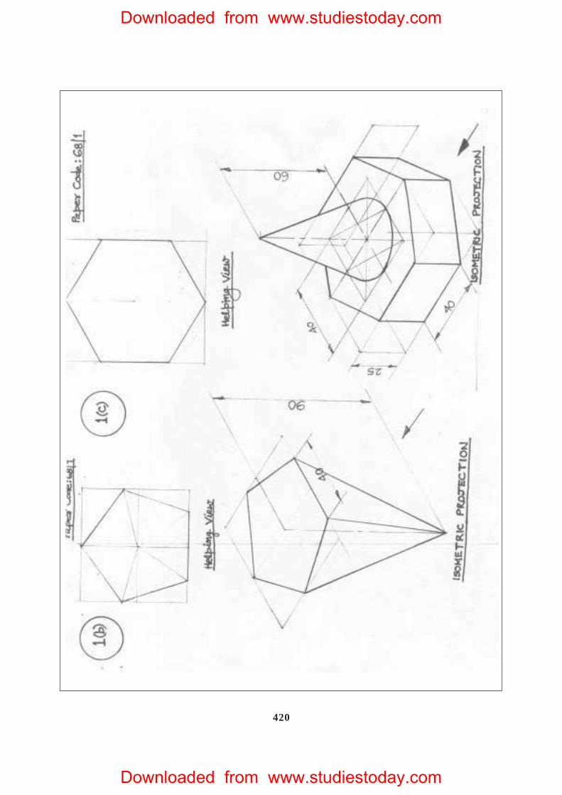
(b) Construct the isometric projection, to isometric scale, of a pentagonal pyramid
(base edge = 40 mm and height = 90 mm), keeping it in the inverted position.
The axis is perpendicular to H.P. One of its base edges is parallel to V.P. and
away from that. Draw the axis and indicate the direction of viewing. Give all
dimensions. 8
(c) A cone (diameter = 40 mm and height = 60 mm) is placed, centrally, with its
base on the hexagonal face of a hexagonal prism (base edge = 40 mm and
height = 25 mm). The common axis is perpendicular to H.P. The base of the
prism is on H.P., and one of the base edges is perpendicular to V.P.
Draw the isometric projection of the solids, placed together, to isometric
scale. Draw the common axis and indicate the direction of viewing. Give all
dimensions. 13
Downloaded from www.studiestoday.com
Downloaded from www.studiestoday.com
409
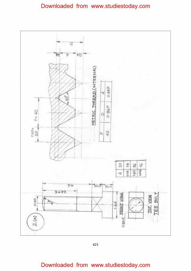
2. (a) Draw to scale 1 : 1, the standard profile of a metric thread (internal), taking
enlarged pitch = 40 mm. Give standard dimensions. 9
OR
Draw to scale 1 : 1, the. front view and top view of a Tee bolt of size M 20.
Keep the axis vertical. Give standard dimensions.
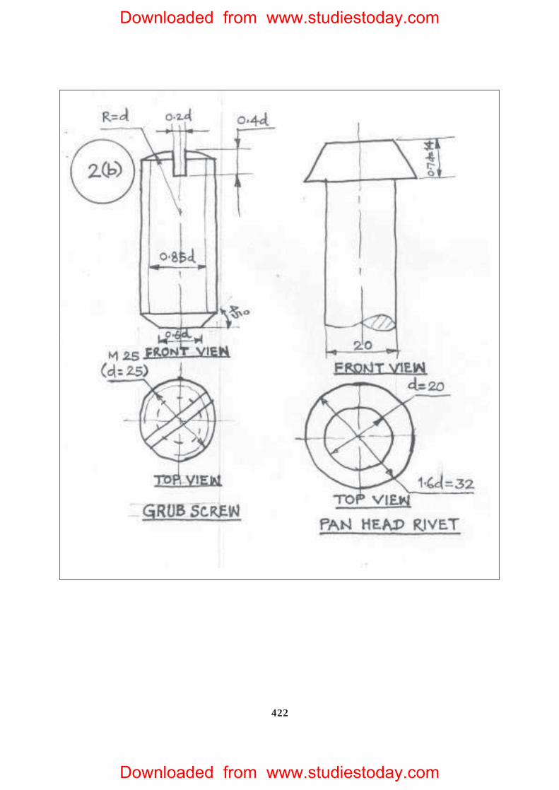
(b) Sketch freehand the front view and top view of a grub screw of size M 25.
Keep the axis vertical. Give standard dimensions. 6
OR
Sketch freehand the front view and the top view of a pan head rivet, shank
diameter = 20 mm. Keep the axis vertical. Give standard dimensions.
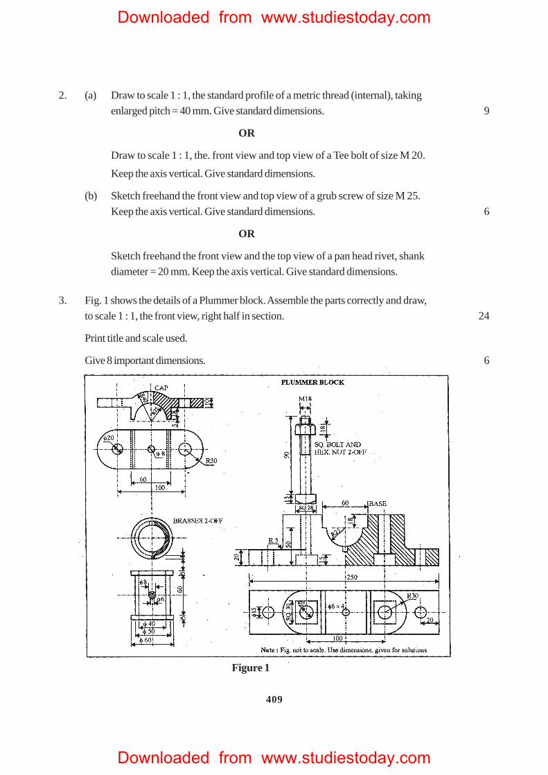
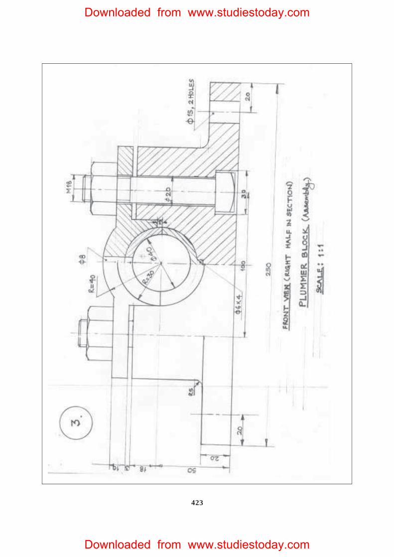
3. Fig. 1 shows the details of a Plummer block. Assemble the parts correctly and draw,
to scale 1 : 1, the front view, right half in section. 24
Print title and scale used.
Give 8 important dimensions. 6
Figure 1
Downloaded from www.studiestoday.com
Downloaded from www.studiestoday.com
410
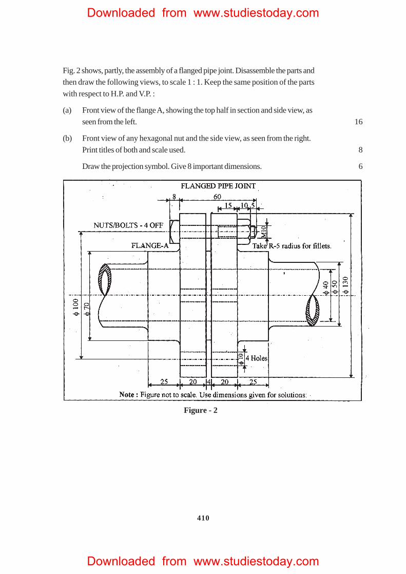
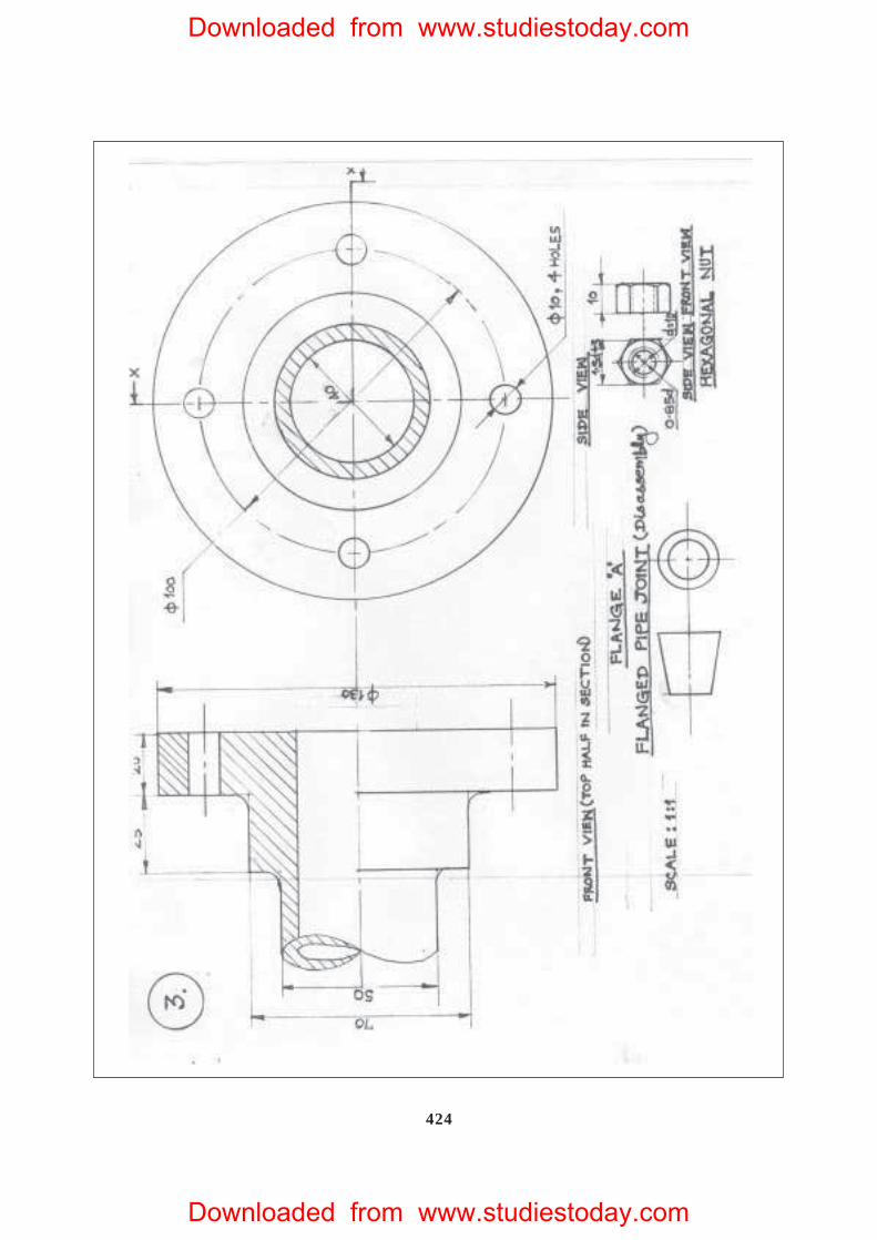
Fig. 2 shows, partly, the assembly of a flanged pipe joint. Disassemble the parts and
then draw the following views, to scale 1 : 1. Keep the same position of the parts
with respect to H.P. and V.P. :
(a) Front view of the flange A, showing the top half in section and side view, as
seen from the left. 16
(b) Front view of any hexagonal nut and the side view, as seen from the right.
Print titles of both and scale used. 8
Draw the projection symbol. Give 8 important dimensions. 6
Figure - 2
Downloaded from www.studiestoday.com
Downloaded from www.studiestoday.com
411
QUESTION PAPER CODE 68
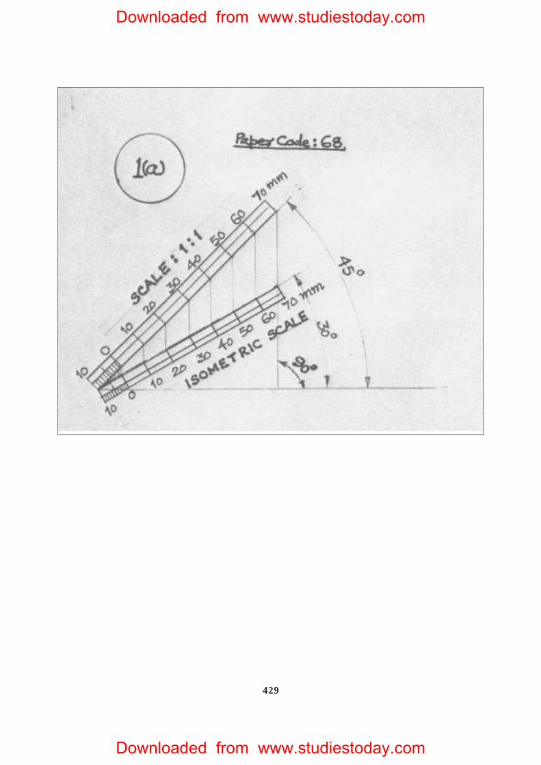
1. (a) Construct an isometric scale 80 mm long. 4
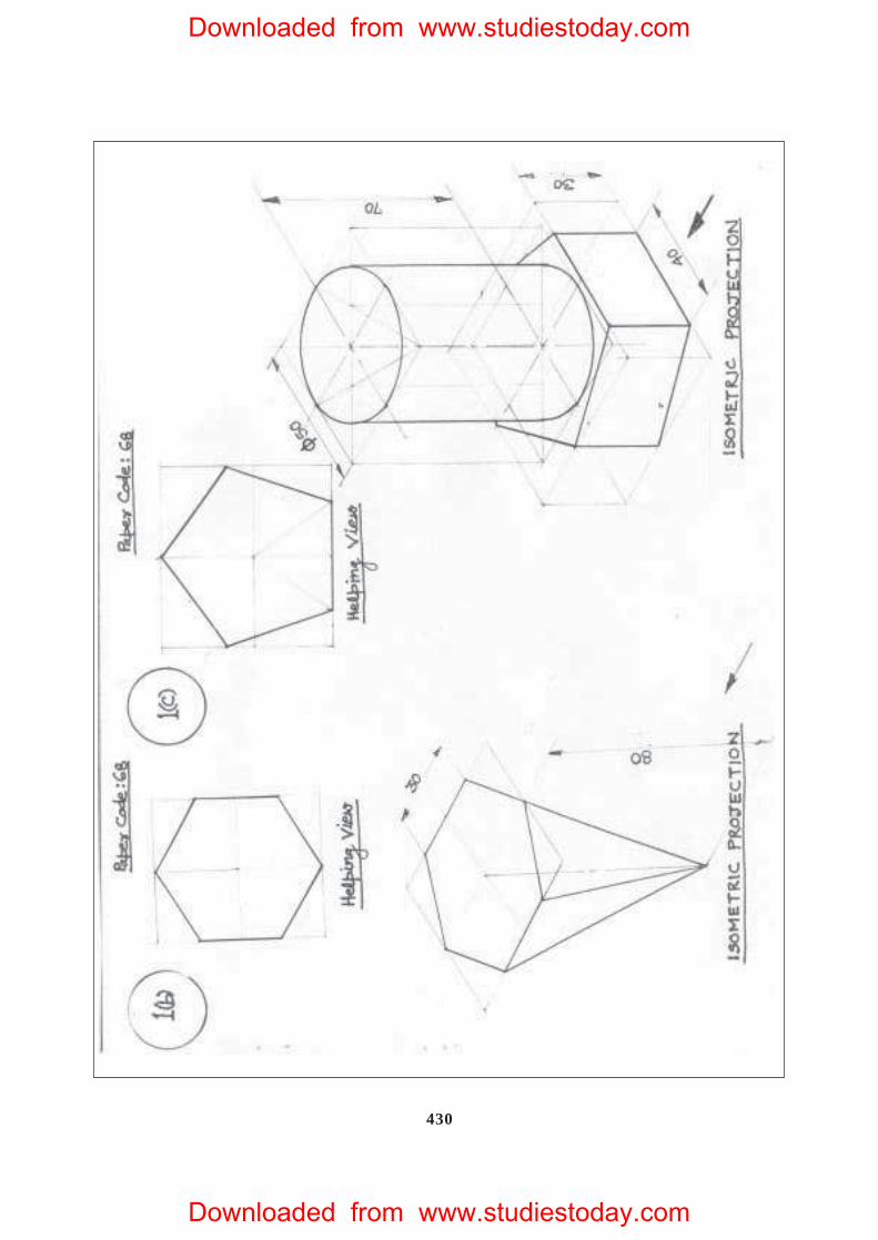
(b) Construct the isometric projection, to isometric scale, of a hexagonal
pyramid (base edge = 30 mm and height = 80 mm) keeping it in the inverted
position. The axis is perpendicular to H.P. One base edge is perpendicular
to V.P.
Draw the axis and indicate the direction of viewing. Give all dimensions. 7
(c) A cylinder (diameter = 50 mm and height = 70 mm) is placed, centrally, with
its circular end on the pentagonal face of a pentagonal prism (base edge = 40
mm and height = 30 mm). The common axis is perpendicular to H.P. The
base of the prism is on H.P. and one of its base edges is parallel to V.P. and
away from it.
Draw the isometric projection of the solids, placed together, to isometric
scale. Draw the common axis and indicate the direction of viewing. Give all
dimensions. 14
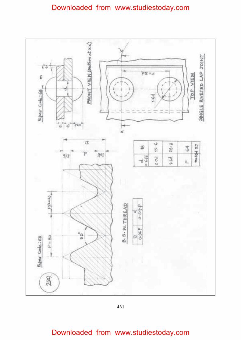
2. (a) Draw to scale 1:1 the standard profile of a B.S.W. thread, taking enlarged
pitch = 50 mm. Give all standard dimensions. 9
OR
Draw the full sectional front view and top view of a single riveted lap joint.
Take plate thickness = 9 mm. Give all standard dimensions. Use scale 1 : 1.
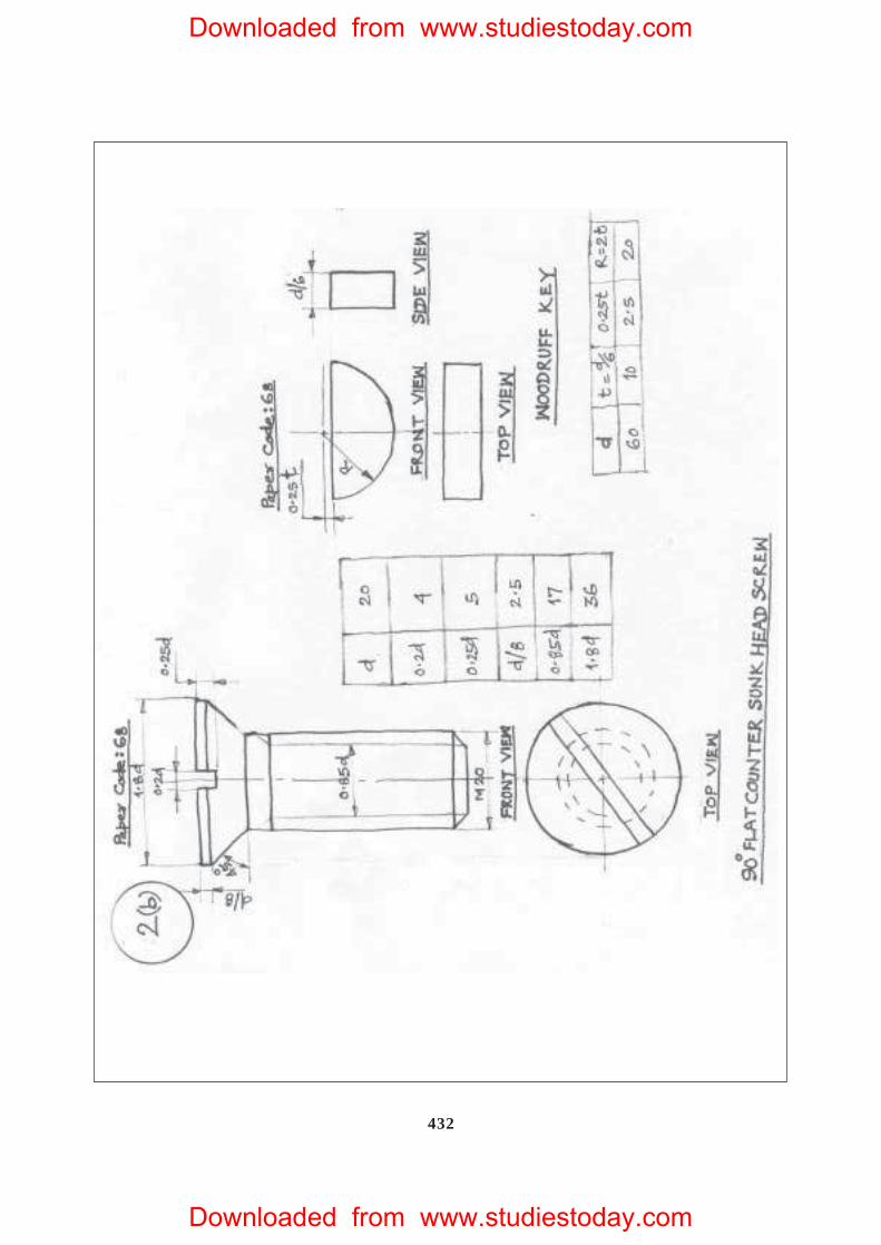
(b) Sketch free-hand the front view and top view of a 90° flat counter sunk
head screw of size M 20, keeping the axis vertical. Give all standard dimen-
sions. 6
OR
Sketch free-hand the front view, top view and side view of a Woodruff key
for a shaft of 60 mm diameter. Give all standard dimensions.
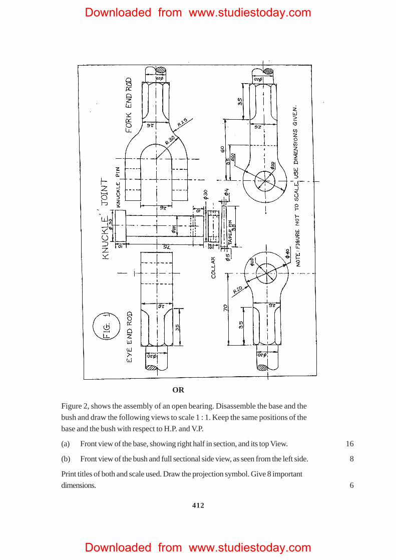
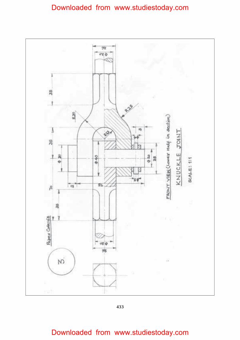
3. Figure 1, shows the details of a knuckle joint. Assemble the parts correctly and then
draw, to scale 1 : 1, the front view, lower half in section. 24
Print title and scale used. Give 8 important dimensions. 6
Downloaded from www.studiestoday.com
Downloaded from www.studiestoday.com
412
OR
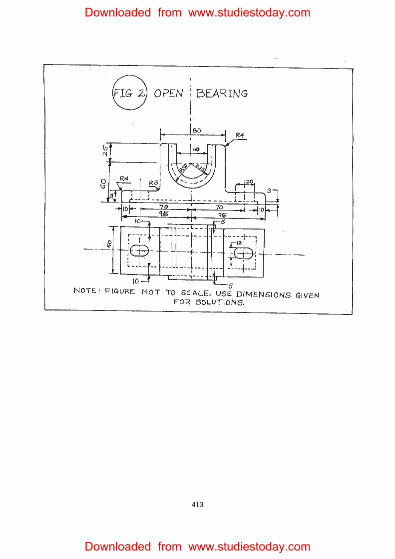
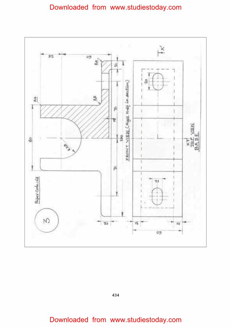
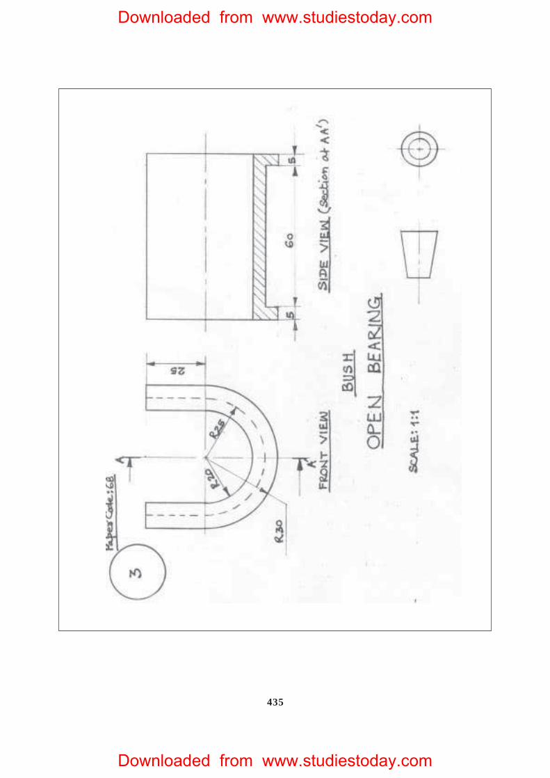
Figure 2, shows the assembly of an open bearing. Disassemble the base and the
bush and draw the following views to scale 1 : 1. Keep the same positions of the
base and the bush with respect to H.P. and V.P.
(a) Front view of the base, showing right half in section, and its top View. 16
(b) Front view of the bush and full sectional side view, as seen from the left side. 8
Print titles of both and scale used. Draw the projection symbol. Give 8 important
dimensions. 6
Downloaded from www.studiestoday.com
Downloaded from www.studiestoday.com
413
Downloaded from www.studiestoday.com
Downloaded from www.studiestoday.com
414
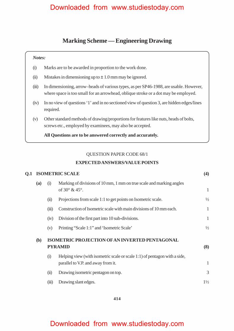
Marking Scheme — Engineering Drawing
Notes:
(i) Marks are to be awarded in proportion to the work done.
(ii) Mistakes in dimensioning up to ± 1.0 mm may be ignored.
(iii) In dimensioning, arrow–heads of various types, as per SP46-1988, are usable. However,
where space is too small for an arrowhead, oblique stroke or a dot may be employed.
(iv) In no view of questions ‘1’ and in no sectioned view of question 3, are hidden edges/lines
required.
(v) Other standard methods of drawing/proportions for features like nuts, heads of bolts,
screws etc., employed by examinees, may also be accepted.
All Questions are to be answered correctly and accurately.
QUESTION PAPER CODE 68/1
EXPECTED ANSWERS/VALUE POINTS
Q.1 ISOMETRIC SCALE (4)
(a) (i) Marking of divisions of 10 mm, 1 mm on true scale and marking angles
of 30° & 45°. 1
(ii) Projections from scale 1:1 to get points on Isometric scale. ½
(iii) Construction of Isometric scale with main divisions of 10 mm each. 1
(iv) Division of the first part into 10 sub-divisions. 1
(v) Printing “Scale 1:1” and ‘Isometric Scale’ ½
(b) ISOMETRIC PROJECTION OF AN INVERTED PENTAGONALPYRAMID (8)
(i) Helping view (with isometric scale or scale 1:1) of pentagon with a side,
parallel to V.P. and away from it. 1
(ii) Drawing isometric pentagon on top. 3
(iii) Drawing slant edges. 1½
Downloaded from www.studiestoday.com
Downloaded from www.studiestoday.com
415
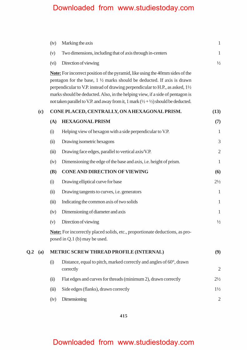
(iv) Marking the axis 1
(v) Two dimensions, including that of axis through in-centers 1
(vi) Direction of viewing ½
Note: For incorrect position of the pyramid, like using the 40mm sides of the
pentagon for the base, 1 ½ marks should be deducted. If axis is drawn
perpendicular to V.P. instead of drawing perpendicular to H.P., as asked, 1½
marks should be deducted. Also, in the helping view, if a side of pentagon is
not taken parallel to V.P. and away from it, 1 mark (½ + ½) should be deducted.
(c) CONE PLACED, CENTRALLY, ON A HEXAGONAL PRISM. (13)
(A) HEXAGONAL PRISM (7)
(i) Helping view of hexagon with a side perpendicular to V.P. 1
(ii) Drawing isometric hexagons 3
(iii) Drawing face edges, parallel to vertical axis/V.P. 2
(iv) Dimensioning the edge of the base and axis, i.e. height of prism. 1
(B) CONE AND DIRECTION OF VIEWING (6)
(i) Drawing elliptical curve for base 2½
(ii) Drawing tangents to curves, i.e. generators 1
(iii) Indicating the common axis of two solids 1
(iv) Dimensioning of diameter and axis 1
(v) Direction of viewing ½
Note: For incorrectly placed solids, etc., proportionate deductions, as pro-
posed in Q.1 (b) may be used.
Q.2 (a) METRIC SCREW THREAD PROFILE (INTERNAL) (9)
(i) Distance, equal to pitch, marked correctly and angles of 60°, drawn
correctly 2
(ii) Flat edges and curves for threads (minimum 2), drawn correctly 2½
(iii) Side edges (flanks), drawn correctly 1½
(iv) Dimensioning 2
Downloaded from www.studiestoday.com
Downloaded from www.studiestoday.com
416
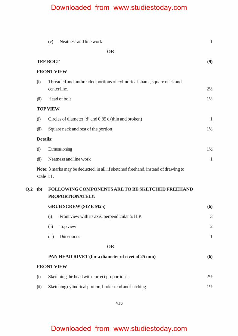
(v) Neatness and line work 1
OR
TEE BOLT (9)
FRONT VIEW
(i) Threaded and unthreaded portions of cylindrical shank, square neck and
center line. 2½
(ii) Head of bolt 1½
TOP VIEW
(i) Circles of diameter ‘d’ and 0.85 d (thin and broken) 1
(ii) Square neck and rest of the portion 1½
Details:
(i) Dimensioning 1½
(ii) Neatness and line work 1
Note: 3 marks may be deducted, in all, if sketched freehand, instead of drawing to
scale 1:1.
Q.2 (b) FOLLOWING COMPONENTS ARE TO BE SKETCHED FREEHAND
PROPORTIONATELY:
GRUB SCREW (SIZE M25) (6)
(i) Front view with its axis, perpendicular to H.P. 3
(ii) Top view 2
(iii) Dimensions 1
OR
PAN HEAD RIVET (for a diameter of rivet of 25 mm) (6)
FRONT VIEW
(i) Sketching the head with correct proportions. 2½
(ii) Sketching cylindrical portion, broken end and hatching 1½
Downloaded from www.studiestoday.com
Downloaded from www.studiestoday.com
417
TOP VIEW
(i) Two circles 1
(ii) Dimensioning 1
Note: 2 marks may be deducted, if these components are drawn with instruments,
instead of being sketched freehand.
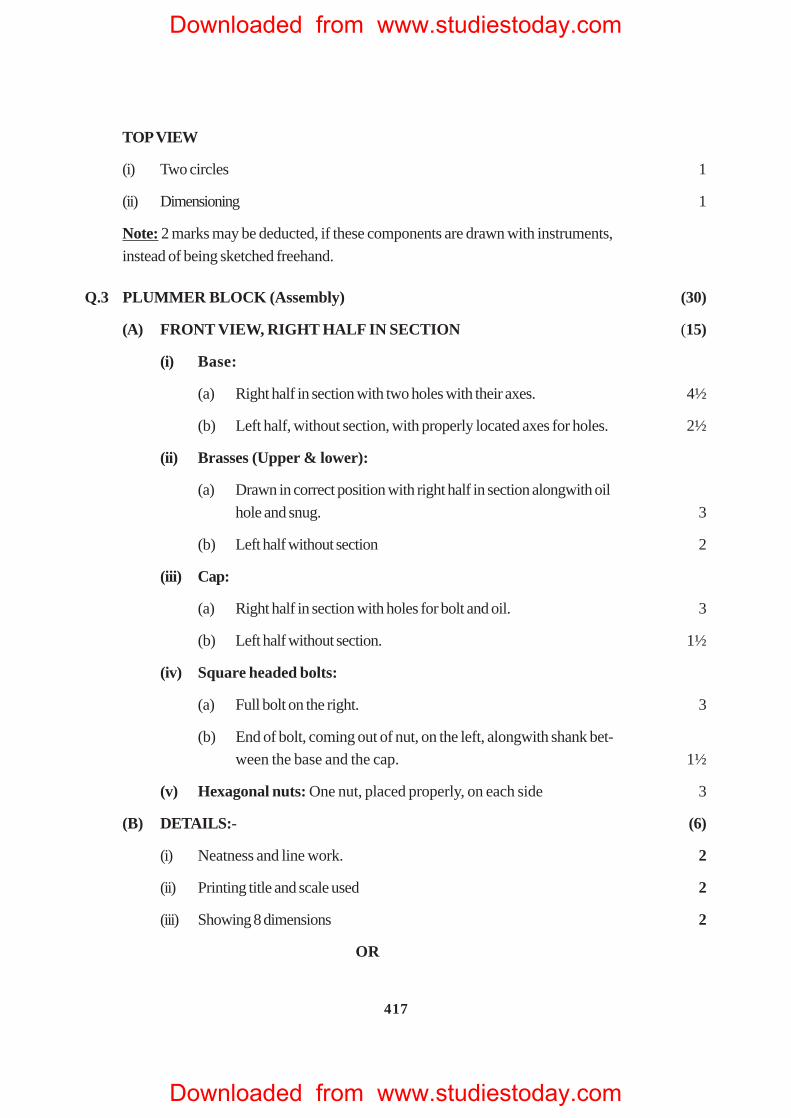
Q.3 PLUMMER BLOCK ( Assembly) (30)
(A) FRONT VIEW, RIGHT HALF IN SECTION (15)
(i) Base:
(a) Right half in section with two holes with their axes. 4½
(b) Left half, without section, with properly located axes for holes. 2½
(ii) Brasses (Upper & lower):
(a) Drawn in correct position with right half in section alongwith oil
hole and snug. 3
(b) Left half without section 2
(iii) Cap:
(a) Right half in section with holes for bolt and oil. 3
(b) Left half without section. 1½
(iv) Square headed bolts:
(a) Full bolt on the right. 3
(b) End of bolt, coming out of nut, on the left, alongwith shank bet-
ween the base and the cap. 1½
(v) Hexagonal nuts: One nut, placed properly, on each side 3
(B) DETAILS:- (6)
(i) Neatness and line work. 2
(ii) Printing title and scale used 2
(iii) Showing 8 dimensions 2
OR
Downloaded from www.studiestoday.com
Downloaded from www.studiestoday.com
418
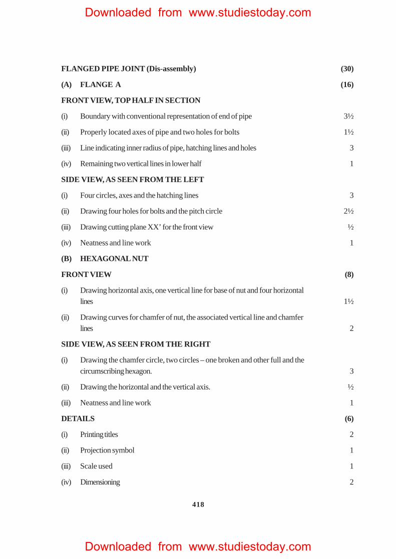
FLANGED PIPE JOINT (Dis-assembly) (30)
(A) FLANGE A (16)
FRONT VIEW, TOP HALF IN SECTION
(i) Boundary with conventional representation of end of pipe 3½
(ii) Properly located axes of pipe and two holes for bolts 1½
(iii) Line indicating inner radius of pipe, hatching lines and holes 3
(iv) Remaining two vertical lines in lower half 1
SIDE VIEW, AS SEEN FROM THE LEFT
(i) Four circles, axes and the hatching lines 3
(ii) Drawing four holes for bolts and the pitch circle 2½
(iii) Drawing cutting plane XX’ for the front view ½
(iv) Neatness and line work 1
(B) HEXAGONAL NUT
FRONT VIEW (8)
(i) Drawing horizontal axis, one vertical line for base of nut and four horizontallines 1½
(ii) Drawing curves for chamfer of nut, the associated vertical line and chamferlines 2
SIDE VIEW, AS SEEN FROM THE RIGHT
(i) Drawing the chamfer circle, two circles – one broken and other full and the
circumscribing hexagon. 3
(ii) Drawing the horizontal and the vertical axis. ½
(iii) N eatness and line work 1
DETAILS (6)
(i) Printing titles 2
(ii) Projection symbol 1
(iii) Scale used 1
(iv) Dimensioning 2
Downloaded from www.studiestoday.com
Downloaded from www.studiestoday.com
419
Downloaded from www.studiestoday.com
Downloaded from www.studiestoday.com
420
Downloaded from www.studiestoday.com
Downloaded from www.studiestoday.com
421
Downloaded from www.studiestoday.com
Downloaded from www.studiestoday.com
422
Downloaded from www.studiestoday.com
Downloaded from www.studiestoday.com
423
Downloaded from www.studiestoday.com
Downloaded from www.studiestoday.com
424
Downloaded from www.studiestoday.com
Downloaded from www.studiestoday.com
425
QUESTION PAPER CODE 68
EXPECTED ANSWERS/VALUE POINTS
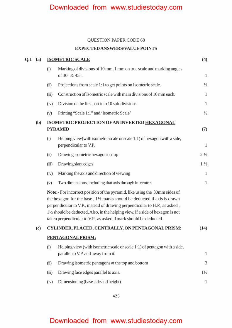
Q.1 (a) ISOMETRIC SCALE (4)
(i) Marking of divisions of 10 mm, 1 mm on true scale and marking angles
of 30° & 45°. 1
(ii) Projections from scale 1:1 to get points on Isometric scale. ½
(iii) Construction of Isometric scale with main divisions of 10 mm each. 1
(iv) Division of the first part into 10 sub-divisions. 1
(v) Printing “Scale 1:1” and ‘Isometric Scale’ ½
(b) ISOMETRIC PROJECTION OF AN INVERTED HEXAGONALPYRAMID (7)
(i) Helping view(with isometric scale or scale 1:1) of hexagon with a side,
perpendicular to V.P. 1
(ii) Drawing isometric hexagon on top 2 ½
(iii) Drawing slant edges 1 ½
(iv) Marking the axis and direction of viewing 1
(v) Two dimensions, including that axis through in-centres 1
Note:- For incorrect position of the pyramid, like using the 30mm sides of
the hexagon for the base , 1½ marks should be deducted if axis is drawn
perpendicular to V.P., instead of drawing perpendicular to H.P., as asked ,
1½ should be deducted, Also, in the helping view, if a side of hexagon is not
taken perpendicular to V.P., as asked, 1mark should be deducted.
(c) CYLINDER, PLACED, CENTRALLY, ON PENTAGONAL PRISM: (14)
PENTAGONAL PRISM:
(i) Helping view (with isometric scale or scale 1:1) of pentagon with a side,
parallel to V.P. and away from it. 1
(ii) Drawing isometric pentagons at the top and bottom 3
(iii) Drawing face edges parallel to axis. 1½
(iv) Dimensioning (base side and height) 1
Downloaded from www.studiestoday.com
Downloaded from www.studiestoday.com
426
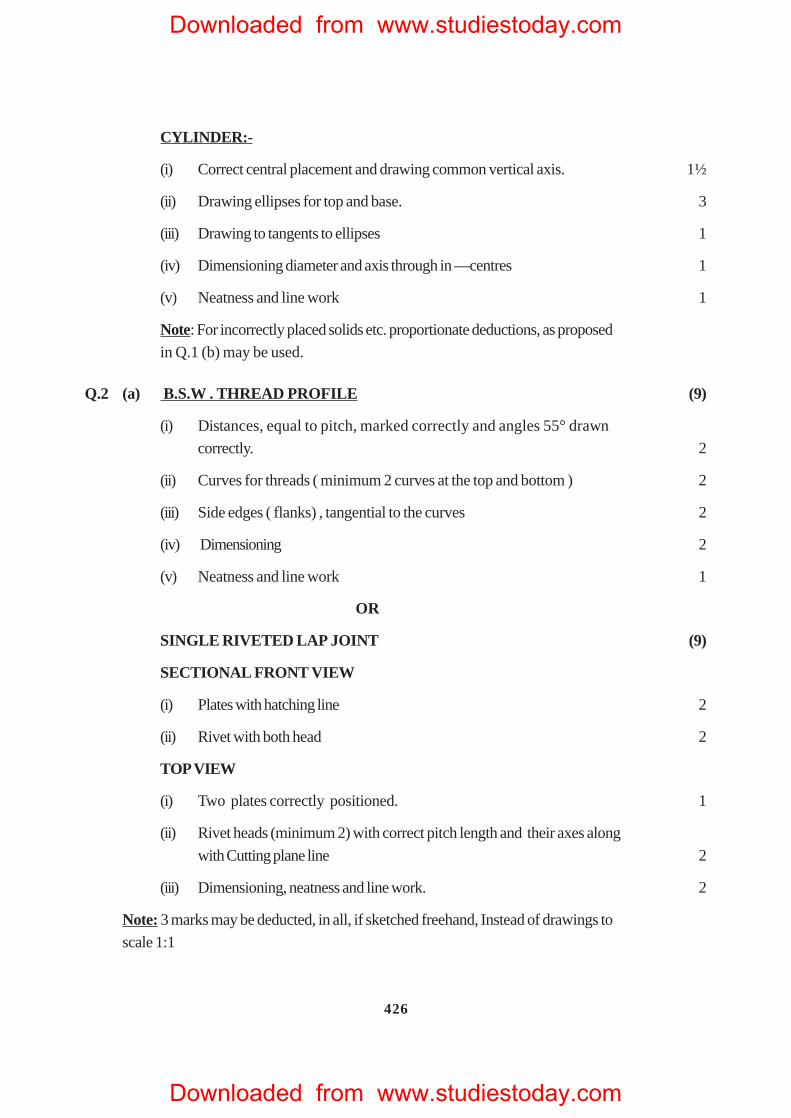
CYLINDER:-
(i) Correct central placement and drawing common vertical axis. 1½
(ii) Drawing ellipses for top and base. 3
(iii) Drawing to tangents to ellipses 1
(iv) Dimensioning diameter and axis through in —centres 1
(v) Neatness and line work 1
Note: For incorrectly placed solids etc. proportionate deductions, as proposed
in Q.1 (b) may be used.
Q.2 (a) B.S.W . THREAD PROFILE (9)
(i) Distances, equal to pitch, marked correctly and angles 55° drawn
correctly. 2
(ii) Curves for threads ( minimum 2 curves at the top and bottom ) 2
(iii) Side edges ( flanks) , tangential to the curves 2
(iv) Dimensioning 2
(v) Neatness and line work 1
OR
SINGLE RIVETED LAP JOINT (9)
SECTIONAL FRONT VIEW
(i) Plates with hatching line 2
(ii) Rivet with both head 2
TOP VIEW
(i) Two plates correctly positioned. 1
(ii) Rivet heads (minimum 2) with correct pitch length and their axes along
with Cutting plane line 2
(iii) Dimensioning, neatness and line work. 2
Note: 3 marks may be deducted, in all, if sketched freehand, Instead of drawings to
scale 1:1
Downloaded from www.studiestoday.com
Downloaded from www.studiestoday.com
427
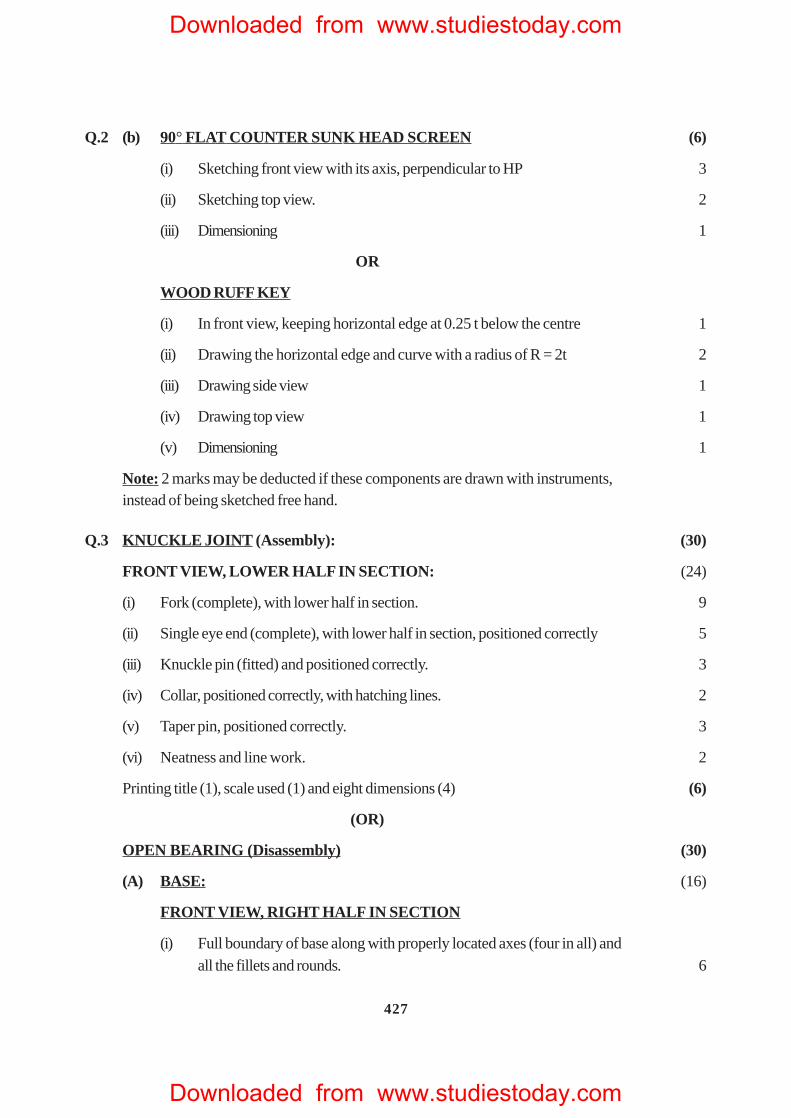
Q.2 (b) 90° FLAT COUNTER SUNK HEAD SCREEN (6)
(i) Sketching front view with its axis, perpendicular to HP 3
(ii) Sketching top view. 2
(iii) Dimensioning 1
OR
WOOD RUFF KEY
(i) In front view, keeping horizontal edge at 0.25 t below the centre 1
(ii) Drawing the horizontal edge and curve with a radius of R = 2t 2
(iii) Drawing side view 1
(iv) Drawing top view 1
(v) Dimensioning 1
Note: 2 marks may be deducted if these components are drawn with instruments,instead of being sketched free hand.
Q.3 KNUCKLE JOINT (Assembly): (30)
FRONT VIEW, LOWER HALF IN SECTION: (24)
(i) Fork (complete), with lower half in section. 9
(ii) Single eye end (complete), with lower half in section, positioned correctly 5
(iii) Knuckle pin (fitted) and positioned correctly. 3
(iv) Collar, positioned correctly, with hatching lines. 2
(v) Taper pin, positioned correctly. 3
(vi) Neatness and line work. 2
Printing title (1), scale used (1) and eight dimensions (4) (6)
(OR)
OPEN BEARING (Disassembly) (30)
(A) BASE: (16)
FRONT VIEW, RIGHT HALF IN SECTION
(i) Full boundary of base along with properly located axes (four in all) andall the fillets and rounds. 6
Downloaded from www.studiestoday.com
Downloaded from www.studiestoday.com
428
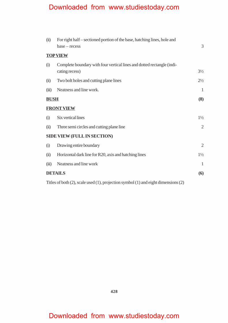
(ii) For right half – sectioned portion of the base, hatching lines, hole and
base – recess 3
TOP VIEW
(i) Complete boundary with four vertical lines and dotted rectangle (indi-
cating recess) 3½
(ii) Two bolt holes and cutting plane lines 2½
(iii) Neatness and line work. 1
BUSH (8)
FRONT VIEW
(i) Six vertical lines 1½
(ii) Three semi circles and cutting plane line 2
SIDE VIEW (FULL IN SECTION)
(i) Drawing entire boundary 2
(ii) Horizontal dark line for R20, axis and hatching lines 1½
(iii) N eatness and line work 1
DETAILS (6)
Titles of both (2), scale used (1), projection symbol (1) and eight dimensions (2)
Downloaded from www.studiestoday.com
Downloaded from www.studiestoday.com
429
Downloaded from www.studiestoday.com
Downloaded from www.studiestoday.com
430
Downloaded from www.studiestoday.com
Downloaded from www.studiestoday.com
431
Downloaded from www.studiestoday.com
Downloaded from www.studiestoday.com
432
Downloaded from www.studiestoday.com
Downloaded from www.studiestoday.com
433
Downloaded from www.studiestoday.com
Downloaded from www.studiestoday.com
434
Downloaded from www.studiestoday.com
Downloaded from www.studiestoday.com
435
Downloaded from www.studiestoday.com
Downloaded from www.studiestoday.com