
ENGINEERING DESIGN GUIDELINE refinery furnace...
27
KLM Technology Group Practical Engineering Guidelines for Processing Plant Solutions SOLUTIONS, STANDARDS AND SOFTWARE www.klmtechgroup.com Page : 1 of 185 Rev: 01 Rev 1 March 2017 KLM Technology Group #03-12 Block Aronia, Jalan Sri Perkasa 2 Taman Tampoi Utama 81200 Johor Bahru Kolmetz Handbook of Process Equipment Design REFINERY FURNACE DESIGN, SIZING AND TROUBLESHOOTING (ENGINEERING DESIGN GUIDELINE Co Authors Rev 1 Apriliana Editor / Author Karl Kolmetz TABLE OF CONTENTS INTRODUCTION 5 Scope 5 General Design Consideration 9 DEFINITION 23 KLM Technology Group has developed; 1) Process Engineering Equipment Design Guidelines, 2) Equipment Design Software, 3) Project Engineering Standards and Specifications, and 4) Unit Operations Manuals. Each has many hours of engineering development. KLM Technology Group believes that if you have a design, consulting, or troubleshooting project you should consider our senior consultants. KLM is providing the introduction to this guideline for free on the internet. Please go to our website to order the complete document. www.klmtechgroup.com
Transcript of ENGINEERING DESIGN GUIDELINE refinery furnace...

KLM Technology
Group
Practical Engineering Guidelines for Processing
Plant Solutions
SOLUTIONS, STANDARDS AND SOFTWARE
www.klmtechgroup.com
Page : 1 of 185
Rev: 01
Rev 1 March 2017
KLM Technology Group #03-12 Block Aronia, Jalan Sri Perkasa 2 Taman Tampoi Utama 81200 Johor Bahru
Kolmetz Handbook
of Process Equipment Design
REFINERY FURNACE DESIGN, SIZING
AND TROUBLESHOOTING
(ENGINEERING DESIGN GUIDELINE
Co Authors Rev 1 Apriliana
Editor / Author Karl Kolmetz
TABLE OF CONTENTS
INTRODUCTION 5 Scope 5 General Design Consideration 9 DEFINITION 23
KLM Technology Group has developed; 1) Process Engineering Equipment Design Guidelines, 2) Equipment Design Software, 3) Project Engineering Standards and Specifications, and 4) Unit Operations Manuals. Each has many hours of engineering development. KLM Technology Group believes that if you have a design, consulting, or troubleshooting project you should consider our senior consultants. KLM is providing the introduction to this guideline for free on the internet. Please go to our website to order the complete document.
www.klmtechgroup.com

KLM Technology Group
Practical Engineering
Guidelines for Processing Plant Solutions
Kolmetz Handbook of Process Equipment Design
REFINERY FURNACE
DESIGN, SIZING AND TROUBLESHOOTING
(ENGINEERING DESIGN GUIDELINE
Page 2 of 185
Rev: 01
March 2017
These design guidelines are believed to be as accurate as possible, but are very general and not for specific design cases. They were designed for engineers to do preliminary designs and process specification sheets. The final design must always be guaranteed for the service selected by the manufacturing vendor, but these guidelines will greatly reduce the amount of up front engineering hours that are required to develop the final design. The guidelines are a training tool for young engineers or a resource for engineers with experience. This document is entrusted to the recipient personally, but the copyright remains with us. It must not be copied, reproduced or in any way communicated or made accessible to third parties without our written consent.
NOMENCLATURE 26 THEORY OF THE DESIGN 28
A. Process Heaters 32
B. Crude Oil Heaters 35
C. Vacuum Heater 42
D. Hydrotreaters Heater 51
E. Catalytic Reforming Process 52
F. General Design Consideration 55
G. Factors Affecting Process Heater Operation 62
H. Burner 71
I. Radiant Section 77
J. Decoking of fire heater tubes 92
K. Convection Section 97
L. Stack 105
M. Auxiliary Equipment 114
N. Efficiency of Furnace 124
O. Design Excess Air 127
P. Trouble shooting 131

KLM Technology Group
Practical Engineering
Guidelines for Processing Plant Solutions
Kolmetz Handbook of Process Equipment Design
REFINERY FURNACE
DESIGN, SIZING AND TROUBLESHOOTING
(ENGINEERING DESIGN GUIDELINE
Page 3 of 185
Rev: 01
March 2017
These design guidelines are believed to be as accurate as possible, but are very general and not for specific design cases. They were designed for engineers to do preliminary designs and process specification sheets. The final design must always be guaranteed for the service selected by the manufacturing vendor, but these guidelines will greatly reduce the amount of up front engineering hours that are required to develop the final design. The guidelines are a training tool for young engineers or a resource for engineers with experience. This document is entrusted to the recipient personally, but the copyright remains with us. It must not be copied, reproduced or in any way communicated or made accessible to third parties without our written consent.
Q. Control Strategies 138 APPLICATION 142 Application 1: Design of furnace with fuel oil 142
Application 2: Design of furnace with fuel gas 149
Application 3: Combustion on Oil-fired heater with natural draught 156
Application 4: Combustion on Gas-fired heater with preheated combustion air 163 REFEREENCE 168 LIST OF TABLE Table 1: The major processes in petroleum refining 29
Table 2: Major Refinery Processes Requiring a Fired Heater 30
Table 3: Average Burner Configuration by Heater Type 34
Table 4: Minimum shape factors and effective diameters for wind loads 58
Table 5: Tube Center-to-center dimensions 59
Table 6: The use of fuel at the burner 74
Table 7: Burner capacity 74
Table 8: Common Heater Tube Sizes and Properties 79
Table 9: Maximum design temperatures for tube-support materials 86
Table 10: Design Conditions for Process Heaters 87
Table 11: Extended surface materials 99
Table 12: Extended surface dimensions 99
Table 13: Thick fins and studs are typically used in the convection section 101
Table 14: Minimum pipe spacing for convection section tubes 102
Table 15: Minimum tube spacing for convection section tubes 102
Table 16: Rotary Sootblower: for Max. Element Length of 10 in 118
Table 17: Rotary Sootblower: for Max. Element Length of 20 in 119
Table 18: Potential Emissions Reductions 141

KLM Technology Group
Practical Engineering
Guidelines for Processing Plant Solutions
Kolmetz Handbook of Process Equipment Design
REFINERY FURNACE
DESIGN, SIZING AND TROUBLESHOOTING
(ENGINEERING DESIGN GUIDELINE
Page 4 of 185
Rev: 01
March 2017
These design guidelines are believed to be as accurate as possible, but are very general and not for specific design cases. They were designed for engineers to do preliminary designs and process specification sheets. The final design must always be guaranteed for the service selected by the manufacturing vendor, but these guidelines will greatly reduce the amount of up front engineering hours that are required to develop the final design. The guidelines are a training tool for young engineers or a resource for engineers with experience. This document is entrusted to the recipient personally, but the copyright remains with us. It must not be copied, reproduced or in any way communicated or made accessible to third parties without our written consent.
LIST OF FIGURE Figure 1: Heater components 7
Figure 2: Convection Section 9
Figure 3: Vertical cylindrical fired heater: (a) all radiant, and (b) helical coil 11
Figure 4: Horizontal tube cabin fired heaters: (a) cabin with convection section and (b) cabin with dividing bridge wall 12
Figure 5: Hoop-tube fired heater 13
Figure 6: Vertical tube box fired heaters 15
Figure 7: Horizontal tube box fired heaters 16
Figure 8: Multiple cell heaters 17
Figure 9: Helical coil fired heater 18
Figure 10: Draft Types 19
Figure 11: Schematic of the heating zones in a process heater. 32
Figure 12: Typical process heater 33
Figure 13: Fired heater size distribution. 35
Figure 14: Crude Distillation Unit (CDU) Process Schematic 36
Figure 15: Arrangement of cabin and vertical heater 37
Figure 16: Typical flow scheme of fluids in fired heater 41
Figure 17: Typical six-pass arrangement of (crude) fired heater 42
Figure 18: Vacuum Distillation Unit (VDU) Process Schematic 43
Figure 19: Typical four-pass arrangement of (vacuum) heater 44
Figure 20: Heat flux gradient with elevation 46
Figure 21: A simplified coker unit process flow diagram 48
Figure 22: Hydrotreating Process Schematic 52
Figure 22: Catalytic Reforming Process Schematic 54
Figure 23: illustration of correct and incorrect draft 64
Figure 24: Burner with correct combustion air 66
Figure 25: Burner with insufficient combustion air 67
Figure 26: Burner with too much combustion air. 68
Figure 27: NOx production increase with increasing excess air 69
Figure 28: Typical natural draft burner (combination gas/liquid burner) 72

KLM Technology Group
Practical Engineering
Guidelines for Processing Plant Solutions
Kolmetz Handbook of Process Equipment Design
REFINERY FURNACE
DESIGN, SIZING AND TROUBLESHOOTING
(ENGINEERING DESIGN GUIDELINE
Page 5 of 185
Rev: 01
March 2017
These design guidelines are believed to be as accurate as possible, but are very general and not for specific design cases. They were designed for engineers to do preliminary designs and process specification sheets. The final design must always be guaranteed for the service selected by the manufacturing vendor, but these guidelines will greatly reduce the amount of up front engineering hours that are required to develop the final design. The guidelines are a training tool for young engineers or a resource for engineers with experience. This document is entrusted to the recipient personally, but the copyright remains with us. It must not be copied, reproduced or in any way communicated or made accessible to third parties without our written consent.
Figure 29: Typical Axial-Flow Burner Forced Draft Combination Gas/Oil Burner 73
Figure 30: The effect of coke (fouling) layer on tube metal temperature 93
Figure 31: Oil cracking: showing time and temperature 94
Figure 32: Decoking on the fired heater tubes 96
Figure 33: Convection section 98
Figure 34: Damper 110
Figure 35: Square Pitch Finned Tubes : Longitudinal Arrangement 116
Figure 36: Triangular Pitch Finned Tubes : Longitudinal Arrangement 116
Figure 37: Square Pitch Finned Tubes : Perpendicular Arrangement 117
Figure 38: Triangular Pitch Finned Tubes : Perpendicular Arrangement 117
Figure 39: Fans and Blower: (a) Natural Draft, (b) Forced Draft, (c) Induced Draft and (d) Balance Draft 121
Figure 40: Plate type air Preheater 123
Figure 41: Typical heater arrangement with non-preheated air 126
Figure 42: Typical heater arrangement with preheated air from an internal heat source 126
Figure 43: Typical heater arrangement with preheated air from an external heat source 127
Figure 44: Relationship between excess air, CO2, O2 and CO 129
Figure 45: The effect of film temperature with coking rate 136
Figure 46: The summary of typical values in furnace 138
Figure 47: Enthalpy of H2O, CO, CO2 and SO2 161
Figure 48: Enthalpy of air, O2 and N2 162

KLM Technology Group
Practical Engineering
Guidelines for Processing Plant Solutions
Kolmetz Handbook of Process Equipment Design
REFINERY FURNACE
DESIGN, SIZING AND TROUBLESHOOTING
(ENGINEERING DESIGN GUIDELINE
Page 6 of 185
Rev: 01
March 2017
These design guidelines are believed to be as accurate as possible, but are very general and not for specific design cases. They were designed for engineers to do preliminary designs and process specification sheets. The final design must always be guaranteed for the service selected by the manufacturing vendor, but these guidelines will greatly reduce the amount of up front engineering hours that are required to develop the final design. The guidelines are a training tool for young engineers or a resource for engineers with experience. This document is entrusted to the recipient personally, but the copyright remains with us. It must not be copied, reproduced or in any way communicated or made accessible to third parties without our written consent.
INTRODUCTION Scope This guideline provides knowledge on designing, operating and troubleshooting a refinery heater. This design guideline can assist in understanding the basic design of refinery heaters with suitable size, materials of construction and heat of combustion. A refinery heater is one of the most important pieces of equipment in a refinery processing plant. Refinery heater’s firing provides a large part of the heat for the process. This heat for the process comes from the combustion of fuels. Fired heaters and boilers are essential components of most refineries, chemical plants and power generation facilities. Process heaters are widely used in petroleum refineries, where they are called refinery heaters. Process heaters are used to transfer heat generated by the combustion of fuels to a fluid other than water contained in tubes. This fluid may either be process fluid or a heat transfer fluid. They are used for pre-heating crude oil and other feed stocks for many refinery processes where the use of steam from boilers may not be practical. One of the problems encountered in refinery fired heater is an imbalance in the heat flux in the individual heater passes. This imbalance may cause high coke formation rates and high tube metal temperatures, which reduce a unit’s capacity and can cause premature failures. Coke formation on the inside of heater tubes reduces the heat transfer through the tubes, which leads to the reduced capacity. The choice of refinery heater style and design is crucial for the best performance of furnace. Factors affecting the performance of refinery heater are influenced by the maximum amount of the heat absorbed, the capacity of burners, process requirements, economics and safety. The theory section explains the selection of the refinery heater type, calculation of sizing, heat transfer concepts and combustion basics. The application of the refinery heater theory with the examples assists the user to study the refinery heater concepts and be prepared to perform the actual design of the refinery heater.

KLM Technology Group
Practical Engineering
Guidelines for Processing Plant Solutions
Kolmetz Handbook of Process Equipment Design
REFINERY FURNACE
DESIGN, SIZING AND TROUBLESHOOTING
(ENGINEERING DESIGN GUIDELINE
Page 7 of 185
Rev: 01
March 2017
These design guidelines are believed to be as accurate as possible, but are very general and not for specific design cases. They were designed for engineers to do preliminary designs and process specification sheets. The final design must always be guaranteed for the service selected by the manufacturing vendor, but these guidelines will greatly reduce the amount of up front engineering hours that are required to develop the final design. The guidelines are a training tool for young engineers or a resource for engineers with experience. This document is entrusted to the recipient personally, but the copyright remains with us. It must not be copied, reproduced or in any way communicated or made accessible to third parties without our written consent.
General Design Consideration Heat is one of most important things in the process plant industry. Equipment that produces and supplies the heat requirement to process plant is called a furnace. Furnaces have high temperatures, open flames, oxygen and fuel; all the components of combustion. The term furnace can also refer to a direct fired heater. They expose hydrocarbon stream to heat that drives a distillation tower, a reactor, and in some cases, change the stream's molecular structure through cracking. Fired heaters and boilers are essential components of most refineries, chemical plants and power generation facilities. Process heaters are used to transfer heat generated by the combustion of fuels to a fluid other than water contained in tubes. This fluid may either be process fluid or a heat transfer fluid. They are used for pre-heating crude oil and other feed stocks for many refinery processes where the use of steam from boilers may not be practical. Process heaters are useful where a temperature higher than that easily obtainable with steam is necessary. Process heaters bum a variety of fuels, including natural gas, refinery and process gas and distillate and residual oils. Process heaters are widely used in petroleum refineries, where they are called refinery heaters. Applications include
• preheating crude oil and other feeds for distillation,
• hydrotreating,
• reforming and
• coking. In some operations, such as thermal cracking, chemical reactions occur in the process heater tubes. Total annual process heater energy consumption in refineries is approximately 2.3 quadrillion Btu, equivalent to a mean of 260,000 MMBtu/hr (on a three-shift, 365-day basis). Typical process heaters can be summarized as follows:
• Start-Up Heater — Starts-up a process unit where it is required to heat up a fluidized bed of catalyst before adding the charge.

KLM Technology Group
Practical Engineering
Guidelines for Processing Plant Solutions
Kolmetz Handbook of Process Equipment Design
REFINERY FURNACE
DESIGN, SIZING AND TROUBLESHOOTING
(ENGINEERING DESIGN GUIDELINE
Page 8 of 185
Rev: 01
March 2017
These design guidelines are believed to be as accurate as possible, but are very general and not for specific design cases. They were designed for engineers to do preliminary designs and process specification sheets. The final design must always be guaranteed for the service selected by the manufacturing vendor, but these guidelines will greatly reduce the amount of up front engineering hours that are required to develop the final design. The guidelines are a training tool for young engineers or a resource for engineers with experience. This document is entrusted to the recipient personally, but the copyright remains with us. It must not be copied, reproduced or in any way communicated or made accessible to third parties without our written consent.
• Fired Reboiler — Provides heat input to a distillation column by heating the column bottoms and vaporizing a portion of it. Used where heat requirement is greater than can be obtained from steam.
• Cracking Furnace — Converts larger molecules into smaller molecules, usually with a catalyst (pyrolysis furnace).
• Process Heater — Brings feed to the required temperature for the next reaction stage.
• Process Heater Vaporizer — Used to heat and partially vaporize a charge prior to distillation.
• Crude Oil Heater — Heats crude oil prior to distillation.
• Reformer Furnace — Chemical conversion by adding steam and feed with catalyst.
Basically, a furnace has four basic components, consisting of box, burner, coil, and stack. The burner will produce the heat then the heat liberated by the combustion of fuel is transfer to a process fluid flowing through tubular coils. Figure 1 show the components of fired heater.

KLM Technology Group
Practical Engineering
Guidelines for Processing Plant Solutions
Kolmetz Handbook of Process Equipment Design
REFINERY FURNACE
DESIGN, SIZING AND TROUBLESHOOTING
(ENGINEERING DESIGN GUIDELINE
Page 9 of 185
Rev: 01
March 2017
These design guidelines are believed to be as accurate as possible, but are very general and not for specific design cases. They were designed for engineers to do preliminary designs and process specification sheets. The final design must always be guaranteed for the service selected by the manufacturing vendor, but these guidelines will greatly reduce the amount of up front engineering hours that are required to develop the final design. The guidelines are a training tool for young engineers or a resource for engineers with experience. This document is entrusted to the recipient personally, but the copyright remains with us. It must not be copied, reproduced or in any way communicated or made accessible to third parties without our written consent.
Figure 1: Heater components (THM)
1. radiant section –portion of the heater in which heat is transferred to the tubes primarily by radiation
2. arch–flat or sloped portion of the heater radiant section opposite the floor
3. convection section –portion of the heater in which the heat is transferred to the tubes primarily by convection
4. crossover–inter-connecting piping between any two heater-coil sections
5. breeching–heater section where flue gases are collected after the last convection coil for transmission to the stack or the outlet ductwork
6. stack–vertical conduit used to discharge flue gas to the atmosphere
7. damper–device for introducing a variable resistance in order to regulate the flow of flue gas or air
Note: In some cases, like smaller forced-draft systems, a damper is not used.

KLM Technology Group
Practical Engineering
Guidelines for Processing Plant Solutions
Kolmetz Handbook of Process Equipment Design
REFINERY FURNACE
DESIGN, SIZING AND TROUBLESHOOTING
(ENGINEERING DESIGN GUIDELINE
Page 10 of 185
Rev: 01
March 2017
These design guidelines are believed to be as accurate as possible, but are very general and not for specific design cases. They were designed for engineers to do preliminary designs and process specification sheets. The final design must always be guaranteed for the service selected by the manufacturing vendor, but these guidelines will greatly reduce the amount of up front engineering hours that are required to develop the final design. The guidelines are a training tool for young engineers or a resource for engineers with experience. This document is entrusted to the recipient personally, but the copyright remains with us. It must not be copied, reproduced or in any way communicated or made accessible to third parties without our written consent.
8. burner–device that introduces fuel and air into a heater at the desired velocities, turbulence and concentration to establish and maintain proper ignition and combustion
Note: Burners are classified by the type of fuel fired, such as oil, gas, or combination (also called dual fuel).
9. pilot–small burner that provides ignition energy to light the main burner
10. terminal–flanged or welded connection to or from the coil providing for inlet and outlet of fluids
11. pass/stream–flow circuit consisting of one or more tubes in series
Figure 2: Convection Section (THM) 1. shield section/shock section–tubes that shield the remaining convection-section tubes
from direct radiation
2. extended surface–heat-transfer surface in the form of fins or studs attached to the heat-absorbing surface

KLM Technology Group
Practical Engineering
Guidelines for Processing Plant Solutions
Kolmetz Handbook of Process Equipment Design
REFINERY FURNACE
DESIGN, SIZING AND TROUBLESHOOTING
(ENGINEERING DESIGN GUIDELINE
Page 11 of 185
Rev: 01
March 2017
These design guidelines are believed to be as accurate as possible, but are very general and not for specific design cases. They were designed for engineers to do preliminary designs and process specification sheets. The final design must always be guaranteed for the service selected by the manufacturing vendor, but these guidelines will greatly reduce the amount of up front engineering hours that are required to develop the final design. The guidelines are a training tool for young engineers or a resource for engineers with experience. This document is entrusted to the recipient personally, but the copyright remains with us. It must not be copied, reproduced or in any way communicated or made accessible to third parties without our written consent.
3. tube support/tube sheet–device used to support tubes
4. header (return bend)–cast or wrought fitting shaped in a 180°bend and used to connect two or more tubes
5. header box–internally insulated structural compartment, separated from the flue-gas stream, which is used to enclose a number of headers or manifolds
In this below are several types of furnace: 1. Vertical cylindrical fired heater
This furnace is commonly used in hot oil service and other processes where the duties are usually small. These heaters are probably the most common in use today and are used for heat duties up to about 150 MBtu/hr. This type of cylindrical upright, tube in the radiant section mounted vertically in a circle round of the burner. The burner is located on the bottom floor, so that the flame is parallel with the tube. Fire heater of this type can be design without or with convection section. Below is kinds of the cross section of vertical-cylindrical fired heater.
a. Vertical cylindrical all radiant:
The all-radiant heater is inexpensive, but since the temperature of flue gases leaving the heater is high, 1500 – 1800oF . Heater of this type does not have convection section. Usually this type have low efficiency and heat duty ranges from 3-7 million kcal/hour.
b. Vertical cylindrical helical coil:
The coil is arranged helically along the cylindrical wall of the combustion chamber. Its primary use is to heat thermal fluids and natural gas. Capacities range from 1 to 30 million Btu/hour.
c. Vertical cylindrical with crossflow convection section:
The convection section is installed above the combustion chamber. Mostly, air preheater are added to increase the efficiency. Heat duty of this type from 5-35 million kcal/hour.
d. Vertical cylindrical with integral convection:

KLM Technology Group
Practical Engineering
Guidelines for Processing Plant Solutions
Kolmetz Handbook of Process Equipment Design
REFINERY FURNACE
DESIGN, SIZING AND TROUBLESHOOTING
(ENGINEERING DESIGN GUIDELINE
Page 12 of 185
Rev: 01
March 2017
These design guidelines are believed to be as accurate as possible, but are very general and not for specific design cases. They were designed for engineers to do preliminary designs and process specification sheets. The final design must always be guaranteed for the service selected by the manufacturing vendor, but these guidelines will greatly reduce the amount of up front engineering hours that are required to develop the final design. The guidelines are a training tool for young engineers or a resource for engineers with experience. This document is entrusted to the recipient personally, but the copyright remains with us. It must not be copied, reproduced or in any way communicated or made accessible to third parties without our written consent.
The distinguishing feature of this type is the use of added surface area on the upper part of the radiant coil to promote convection heating. This type is added surface area on the upper part of the radiant coil to promote convection heating. Duties are from 2.5 – 25 million kcal /hr.
(a) (b)
Figure 3: Vertical cylindrical fired heater: (a) all radiant and (b) helical coil
Convection coil
Radiant
coil
Burner
Radiant
coil
Burner
Convection coil

KLM Technology Group
Practical Engineering
Guidelines for Processing Plant Solutions
Kolmetz Handbook of Process Equipment Design
REFINERY FURNACE
DESIGN, SIZING AND TROUBLESHOOTING
(ENGINEERING DESIGN GUIDELINE
Page 13 of 185
Rev: 01
March 2017
These design guidelines are believed to be as accurate as possible, but are very general and not for specific design cases. They were designed for engineers to do preliminary designs and process specification sheets. The final design must always be guaranteed for the service selected by the manufacturing vendor, but these guidelines will greatly reduce the amount of up front engineering hours that are required to develop the final design. The guidelines are a training tool for young engineers or a resource for engineers with experience. This document is entrusted to the recipient personally, but the copyright remains with us. It must not be copied, reproduced or in any way communicated or made accessible to third parties without our written consent.
2. Horizontal tube cabin fired heaters This cabin has room type consists of the radiation and convection. Tube-tube mounted horizontally while the burner is located on the floor furnace, so that the flame is not straight and parallel to the wall heater. The first layer of tubes in the convection section directly facing into combustion chamber or the radiant fire box called shield tubes. The burner mounted on the floor of the cabin and fire is directed vertically. Cabin fired heater have some variation in the application. It is like cabin furnace with a centre wall. In the figure below the fire heater usually can be used for the large fired heater and has two separate heating zones are required in the radiant section. This design is economical, high efficiency duties are from 20 - 50 million kcal/hour. In many operations, about 75% of the heat is absorbed in the radiant zone of a fired heater.

KLM Technology Group
Practical Engineering
Guidelines for Processing Plant Solutions
Kolmetz Handbook of Process Equipment Design
REFINERY FURNACE
DESIGN, SIZING AND TROUBLESHOOTING
(ENGINEERING DESIGN GUIDELINE
Page 14 of 185
Rev: 01
March 2017
These design guidelines are believed to be as accurate as possible, but are very general and not for specific design cases. They were designed for engineers to do preliminary designs and process specification sheets. The final design must always be guaranteed for the service selected by the manufacturing vendor, but these guidelines will greatly reduce the amount of up front engineering hours that are required to develop the final design. The guidelines are a training tool for young engineers or a resource for engineers with experience. This document is entrusted to the recipient personally, but the copyright remains with us. It must not be copied, reproduced or in any way communicated or made accessible to third parties without our written consent.
(a) (b)
Figure 4: Horizontal tube cabin fired heaters: (a) cabin with convection section and (b) cabin with dividing bridge wall
3. Hoop-tube fired heater This fire heater has tube bent like U-type with vertically oriented. In all-vapor flow, non-coking services where low coil pressure drop is desired. This design is used where the pressure drop must be very low since the path through each tube provides
Convection coil
Radiant
coil
Burner
Convection coil
Radiant
coil
Burner

KLM Technology Group
Practical Engineering
Guidelines for Processing Plant Solutions
Kolmetz Handbook of Process Equipment Design
REFINERY FURNACE
DESIGN, SIZING AND TROUBLESHOOTING
(ENGINEERING DESIGN GUIDELINE
Page 15 of 185
Rev: 01
March 2017
These design guidelines are believed to be as accurate as possible, but are very general and not for specific design cases. They were designed for engineers to do preliminary designs and process specification sheets. The final design must always be guaranteed for the service selected by the manufacturing vendor, but these guidelines will greatly reduce the amount of up front engineering hours that are required to develop the final design. The guidelines are a training tool for young engineers or a resource for engineers with experience. This document is entrusted to the recipient personally, but the copyright remains with us. It must not be copied, reproduced or in any way communicated or made accessible to third parties without our written consent.
a design with many passes. Application of this type is in the catalytic reformers charge heater. Duties are from 13-25 million kcal/hr.
Figure 5: Hoop-tube fired heater
Convection coil
Radiant
coil
Burner
Terminal monitors

KLM Technology Group
Practical Engineering
Guidelines for Processing Plant Solutions
Kolmetz Handbook of Process Equipment Design
REFINERY FURNACE
DESIGN, SIZING AND TROUBLESHOOTING
(ENGINEERING DESIGN GUIDELINE
Page 16 of 185
Rev: 01
March 2017
These design guidelines are believed to be as accurate as possible, but are very general and not for specific design cases. They were designed for engineers to do preliminary designs and process specification sheets. The final design must always be guaranteed for the service selected by the manufacturing vendor, but these guidelines will greatly reduce the amount of up front engineering hours that are required to develop the final design. The guidelines are a training tool for young engineers or a resource for engineers with experience. This document is entrusted to the recipient personally, but the copyright remains with us. It must not be copied, reproduced or in any way communicated or made accessible to third parties without our written consent.
4. Vertical tube box fired heaters In this fire heater, tubes stand vertically along wall in the radiant section. Vertical radiant tubes are arranged in a single row in each combustion cell (there are often two cells) and are fired from both sides of the row. Such an arrangement yields a uniform distribution of heat-transfer rates about the tube circumference. This heater is suitable for the large forced-draft burners. Requirement of heat input to each cell provided by burner.
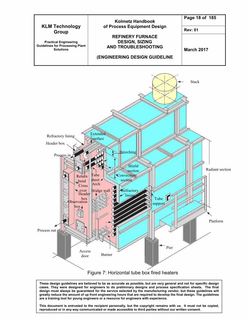
5. Horizontal tube box fired heaters
The radiant and convection section in a typical of horizontal tube box in the Figure 5 are separate by a wall called bridge wall. Function of bridge wall is to create a good direction of flame and to stream the smoke in to flue stack. Burners are firing from the floor along both sides of the bridge wall. Duties are from 30 to 8 million kcal /hour.
6. Multiple cell heaters For two-cell horizontal tube box have high efficiency, duties from 25-65 million kcal/hour.
7. Helical coil fired heater This heater configuration is commonly used where the duties are small. Since each pass consists of a separate winding of the coil, pressure drop options are limited. Many of these only have a radiant section, since efficiency is often not that critical, especially in intermittent services like for a regeneration heater.

KLM Technology Group
Practical Engineering
Guidelines for Processing Plant Solutions
Kolmetz Handbook of Process Equipment Design
REFINERY FURNACE
DESIGN, SIZING AND TROUBLESHOOTING
(ENGINEERING DESIGN GUIDELINE
Page 17 of 185
Rev: 01
March 2017
These design guidelines are believed to be as accurate as possible, but are very general and not for specific design cases. They were designed for engineers to do preliminary designs and process specification sheets. The final design must always be guaranteed for the service selected by the manufacturing vendor, but these guidelines will greatly reduce the amount of up front engineering hours that are required to develop the final design. The guidelines are a training tool for young engineers or a resource for engineers with experience. This document is entrusted to the recipient personally, but the copyright remains with us. It must not be copied, reproduced or in any way communicated or made accessible to third parties without our written consent.
Figure 6: Vertical tube box fired heaters
To Stack
Burners
2 side fired center
tubes
1 side fired wall
tubes
Forced air
supply direct
KLM Technology Group
Practical Engineering
Guidelines for Processing Plant Solutions
Kolmetz Handbook of Process Equipment Design
REFINERY FURNACE
DESIGN, SIZING AND TROUBLESHOOTING
(ENGINEERING DESIGN GUIDELINE
Page 18 of 185
Rev: 01
March 2017
These design guidelines are believed to be as accurate as possible, but are very general and not for specific design cases. They were designed for engineers to do preliminary designs and process specification sheets. The final design must always be guaranteed for the service selected by the manufacturing vendor, but these guidelines will greatly reduce the amount of up front engineering hours that are required to develop the final design. The guidelines are a training tool for young engineers or a resource for engineers with experience. This document is entrusted to the recipient personally, but the copyright remains with us. It must not be copied, reproduced or in any way communicated or made accessible to third parties without our written consent.
Figure 7: Horizontal tube box fired heaters
Refractory lining
Platform
Pier
Burner
Process out
Radiant section
Header box
Process in
Access
door
Header
box
Cross
over
Return
bend
Tube
sheet
Observation
box
Arch
Bridge wall
Extended
surface
Breeching
Shield
section
Convection
section
Refractory
lining Tube
support
Stack

KLM Technology Group
Practical Engineering
Guidelines for Processing Plant Solutions
Kolmetz Handbook of Process Equipment Design
REFINERY FURNACE
DESIGN, SIZING AND TROUBLESHOOTING
(ENGINEERING DESIGN GUIDELINE
Page 19 of 185
Rev: 01
March 2017
These design guidelines are believed to be as accurate as possible, but are very general and not for specific design cases. They were designed for engineers to do preliminary designs and process specification sheets. The final design must always be guaranteed for the service selected by the manufacturing vendor, but these guidelines will greatly reduce the amount of up front engineering hours that are required to develop the final design. The guidelines are a training tool for young engineers or a resource for engineers with experience. This document is entrusted to the recipient personally, but the copyright remains with us. It must not be copied, reproduced or in any way communicated or made accessible to third parties without our written consent.
Figure 8: Multiple cell heaters
Convection coil
Radiant
coil
Burner Burner

KLM Technology Group
Practical Engineering
Guidelines for Processing Plant Solutions
Kolmetz Handbook of Process Equipment Design
REFINERY FURNACE
DESIGN, SIZING AND TROUBLESHOOTING
(ENGINEERING DESIGN GUIDELINE
Page 20 of 185
Rev: 01
March 2017
These design guidelines are believed to be as accurate as possible, but are very general and not for specific design cases. They were designed for engineers to do preliminary designs and process specification sheets. The final design must always be guaranteed for the service selected by the manufacturing vendor, but these guidelines will greatly reduce the amount of up front engineering hours that are required to develop the final design. The guidelines are a training tool for young engineers or a resource for engineers with experience. This document is entrusted to the recipient personally, but the copyright remains with us. It must not be copied, reproduced or in any way communicated or made accessible to third parties without our written consent.
Figure 9: Helical coil fired heater

KLM Technology Group
Practical Engineering
Guidelines for Processing Plant Solutions
Kolmetz Handbook of Process Equipment Design
REFINERY FURNACE
DESIGN, SIZING AND TROUBLESHOOTING
(ENGINEERING DESIGN GUIDELINE
Page 21 of 185
Rev: 01
March 2017
These design guidelines are believed to be as accurate as possible, but are very general and not for specific design cases. They were designed for engineers to do preliminary designs and process specification sheets. The final design must always be guaranteed for the service selected by the manufacturing vendor, but these guidelines will greatly reduce the amount of up front engineering hours that are required to develop the final design. The guidelines are a training tool for young engineers or a resource for engineers with experience. This document is entrusted to the recipient personally, but the copyright remains with us. It must not be copied, reproduced or in any way communicated or made accessible to third parties without our written consent.
Various liquid and gas fuels are fired. These include natural gas, refinery fuel gas, propane, fuel oils, residual oils and refinery waste gases. Each has advantages and disadvantages. Cleaner burning fuels are those that produce very little particulate and sulphur oxide emissions. Unless nitrogen oxide emissions are a concern, emission control systems are not typically required. Natural gas is generally considered to be the cleanest of fuels. The downside with using clean fuels can be fuel costs. Over 75 percent of process heaters are natural draft; air is drawn to the burners by a pressure differential created by the heat of combustion. Natural draft heaters are simpler and less expensive to construct, Another type of process heater, the mechanical draft heaters, uses one or more fans to supply combustion air to, and remove flue gases from, the heater. Further, mechanical draft systems can use combustion air preheat, which increases energy efficiency and decreases fuel consumption. However, higher heater temperatures that result from the use of preheated combustion air lead to increased thermal NOx formation in the heater. This accounts for higher NOx emissions from mechanical draft heaters than from natural draft heaters.
(a) (b) (c) (d) (a) natural draft –heater in which a stack effect induces the combustion air and removes the flue gases

KLM Technology Group
Practical Engineering
Guidelines for Processing Plant Solutions
Kolmetz Handbook of Process Equipment Design
REFINERY FURNACE
DESIGN, SIZING AND TROUBLESHOOTING
(ENGINEERING DESIGN GUIDELINE
Page 22 of 185
Rev: 01
March 2017
These design guidelines are believed to be as accurate as possible, but are very general and not for specific design cases. They were designed for engineers to do preliminary designs and process specification sheets. The final design must always be guaranteed for the service selected by the manufacturing vendor, but these guidelines will greatly reduce the amount of up front engineering hours that are required to develop the final design. The guidelines are a training tool for young engineers or a resource for engineers with experience. This document is entrusted to the recipient personally, but the copyright remains with us. It must not be copied, reproduced or in any way communicated or made accessible to third parties without our written consent.
(b) forced-draft –heater for which combustion air is supplied by a fan or other mechanical means
(c) induced-draft –heater that uses a fan to remove flue gases and to maintain negative pressure in the heater to induce combustion air without a forced-draft fan
(d) balanced draft –heater that uses forced-draft fans to supply combustion air and uses induced draft fans to remove the flue gases
Figure 10: Draft Types
DEFINITIONS Air Preheater - Heat exchanger device that uses some of the heat in the flue gases to raise the temperature of the air supply to the burners. Breeching - The hood that collects the flue gas at the convection section exit. Bridge-wall Temperature - The temperature of the flue gas leaving the radiant section Bulk Temperature - The average temperature of the process fluid at any tube cross section. Center Wall - A refractory wall in the radiant section, which divides it into two separate cells. Coil - A series of straight tube lengths connected by 180o return bends, forming a continuous path through which the process fluid passes and is heated. Convection Section - The portion of a heater, consisting of a bank of tubes, which receives heat from the hot flue gases, mainly by convection. Corbelling - Narrow ledges extending from the convection section side walls to prevent flue gas from flowing preferentially up the side of the convection section, between the wall and the nearest tubes. Crossover - Piping which transfers the process fluid either externally or internally from one section of the heater to another.

KLM Technology Group
Practical Engineering
Guidelines for Processing Plant Solutions
Kolmetz Handbook of Process Equipment Design
REFINERY FURNACE
DESIGN, SIZING AND TROUBLESHOOTING
(ENGINEERING DESIGN GUIDELINE
Page 23 of 185
Rev: 01
March 2017
These design guidelines are believed to be as accurate as possible, but are very general and not for specific design cases. They were designed for engineers to do preliminary designs and process specification sheets. The final design must always be guaranteed for the service selected by the manufacturing vendor, but these guidelines will greatly reduce the amount of up front engineering hours that are required to develop the final design. The guidelines are a training tool for young engineers or a resource for engineers with experience. This document is entrusted to the recipient personally, but the copyright remains with us. It must not be copied, reproduced or in any way communicated or made accessible to third parties without our written consent.
Damper - A device to regulate flow of gas through a stack or duct and to control draft in a heater. Draft - The negative pressure (vacuum) at a given point inside the heater, usually expressed in inches of water. Excess Air - The percentage of air in the heater in excess of the stoichiometric amount required for combustion. Extended Surface - Surface added to the outside of bare tubes in the convection section to provide more heat transfer area. Film - A thin fluid layer adjacent to a pipe wall that remains in laminar flow, even when the bulk flow is turbulent. Film Temperature - The maximum temperature in the film, at the tube wall. Fire Box - A term used to describe the structure which surrounds the radiant coils and into which the burners protrude. Flue Gas - A mixture of gaseous products resulting from combustion of the fuel. Fouling - The building up of a film of dirt, ash, soot or coke on heat transfer surfaces, resulting in increased resistance to heat flow. Forced Draft - Use of a fan to supply combustion air to the burners and to overcome the pressure drop through the burners. Fired Heater Efficiency - The ratio of heat absorbed to heat fired, on a lower heating value basis. Header Box - The compartment at the end of the convection section where the headers are located.

KLM Technology Group
Practical Engineering
Guidelines for Processing Plant Solutions
Kolmetz Handbook of Process Equipment Design
REFINERY FURNACE
DESIGN, SIZING AND TROUBLESHOOTING
(ENGINEERING DESIGN GUIDELINE
Page 24 of 185
Rev: 01
March 2017
These design guidelines are believed to be as accurate as possible, but are very general and not for specific design cases. They were designed for engineers to do preliminary designs and process specification sheets. The final design must always be guaranteed for the service selected by the manufacturing vendor, but these guidelines will greatly reduce the amount of up front engineering hours that are required to develop the final design. The guidelines are a training tool for young engineers or a resource for engineers with experience. This document is entrusted to the recipient personally, but the copyright remains with us. It must not be copied, reproduced or in any way communicated or made accessible to third parties without our written consent.
Heat Available - The heat absorbed from the products of combustion (flue gas) as they are cooled from the flame temperature to a given flue gas temperature. Heat Density - The rate of heat transfer per unit area to a tube, usually based on total outside surface area. Heat Duty - The total heat absorbed by the process fluid, usually expressed in MBtu/hr Induced Draft - Use of a fan to provide the additional draft required over that supplied by the stack, to draw the flue gas through the convection section, and any downstream heat recovery equipment. Lower Heating Value (LHV) - The theoretical heat of combustion of a fuel, when no credit is taken for the heat of condensation of water in the flue gas. Mass Velocity - The mass flow rate per unit of flow area through the coil. Typical units are lb/s-sq. ft. Natural Draft - System in which the draft required to move combustion air into the heater and flue gas through the heater and out the stack is provided by stack effect alone. Net Fuel - The fuel that would be required in the heater if there were no radiation losses. One-Side Fired Tubes - Radiant section tubes located adjacent to a heater wall have only one side directly exposed to a burner flame. Radiation to the back side of the tubes is by reflection/ re-radiation from the refractory wall. Pass - A coil that transports the process fluid from fired heater inlet to outlet. Radiant Section - The section of the fired heater in which heat is transferred to the heater tubes primarily by radiation from high-temperature flue gas. Service Factor – A measure of the continuity of operation, generally expressed as the ratio of total running days for a given time period to the total calendar days in the period. Shield Section - The first two tube rows of the convection section.

KLM Technology Group
Practical Engineering
Guidelines for Processing Plant Solutions
Kolmetz Handbook of Process Equipment Design
REFINERY FURNACE
DESIGN, SIZING AND TROUBLESHOOTING
(ENGINEERING DESIGN GUIDELINE
Page 25 of 185
Rev: 01
March 2017
These design guidelines are believed to be as accurate as possible, but are very general and not for specific design cases. They were designed for engineers to do preliminary designs and process specification sheets. The final design must always be guaranteed for the service selected by the manufacturing vendor, but these guidelines will greatly reduce the amount of up front engineering hours that are required to develop the final design. The guidelines are a training tool for young engineers or a resource for engineers with experience. This document is entrusted to the recipient personally, but the copyright remains with us. It must not be copied, reproduced or in any way communicated or made accessible to third parties without our written consent.
Sootblower - A steam lance (usually movable) in the convection section for blowing soot and ash from the tubes using high-pressure steam. Stack - A cylindrical steel, concrete or brick shell which carries flue gas to the atmosphere and provides necessary draft. Stack Effect - The difference between the weight of a column of high-temperature gases inside the heater and/or stack and the weight of an equivalent column of external air, usually expressed in inches of water per foot of height. Stack Temperature - The temperature of the flue gas as it leaves the convection section, or air preheater directly upstream of the stack. Two-Side Fired Tubes - Radiant section tubes which are exposed on both sides to direct radiation from the burners. NOMENCLATURES Acp Cold plane area, (ft2) Ar Radiant surface area (ft2) Arl Right and left area (ft) Ashield Tube shield area, (ft2) Atube Area of tube, (ft2) Aw Refractory surface (ft2) C Capacity design (btu/hr) C/H C/H ratio, % cpa Specific heat capacity of the air, Btu/lb.°F cpf Specific heat capacity of the fuel, Btu/lb.°F cpm Specific heat capacity of the atomizing medium, Btu/lb.°F ef Fuel efficiency, % Eff Efficiency of furnace, % eg Gross thermal efficiency, % F Exchange factor G Flue gas flow rate (lb/sec ft2)

KLM Technology Group
Practical Engineering
Guidelines for Processing Plant Solutions
Kolmetz Handbook of Process Equipment Design
REFINERY FURNACE
DESIGN, SIZING AND TROUBLESHOOTING
(ENGINEERING DESIGN GUIDELINE
Page 26 of 185
Rev: 01
March 2017
These design guidelines are believed to be as accurate as possible, but are very general and not for specific design cases. They were designed for engineers to do preliminary designs and process specification sheets. The final design must always be guaranteed for the service selected by the manufacturing vendor, but these guidelines will greatly reduce the amount of up front engineering hours that are required to develop the final design. The guidelines are a training tool for young engineers or a resource for engineers with experience. This document is entrusted to the recipient personally, but the copyright remains with us. It must not be copied, reproduced or in any way communicated or made accessible to third parties without our written consent.
Gf Flue gas rate, (lb/hr) H Shell height (ft) HCS Height of convection section (in) hH Higher massic heat, Btu/lb hL Lower massic heat value of the fuel burned, btu/lb Hpersection Height per section (in) hr Radiation massic heat loss, btu/lb hs Massic heat content, btu/lb Hwall Wall height (ft) L Shell length (ft) Lbft The total length of bare of finned tubes, (ft) Lbm Mean beam length (ft) Lexp Exposed length (ft) mst Mass of atomizing steam per unit mass of fuel, lb/lb Nbsection Number of radiant burner per section Nburner The number of burner Nr Amount of radiant section Nt1 section Number of tube in 1 section Ntc Number of tube in ceiling area, Ntchamber Number of tube in 1 chamber, Ntr Number of tube in radiant section, Ntrl Number of tube in right and left area, Ntrl Number of tube in right and left area, Nts Number of tube in shield area, OD Outside tube diameter (in) P Partial pressure of CO2 and H2O (atm) Pvap Vapour pressure of water at the ambient temperature, mbar a Qa Heat absorbed needed (btu/hr) Qconv Heat in convective zone, (btu/lb) Qn Heat released (btu/lb) Qra Radiant heat absorption (btu/hr) Qrac Radiant heat absorbed calculated (btu/hr) Qrf Radiant heat flux (btu/hr ft2) Qrfc Radiant heat flux (btu/hr ft2) RH Relatieve humadity, % rl adiation heat loss, %

KLM Technology Group
Practical Engineering
Guidelines for Processing Plant Solutions
Kolmetz Handbook of Process Equipment Design
REFINERY FURNACE
DESIGN, SIZING AND TROUBLESHOOTING
(ENGINEERING DESIGN GUIDELINE
Page 27 of 185
Rev: 01
March 2017
These design guidelines are believed to be as accurate as possible, but are very general and not for specific design cases. They were designed for engineers to do preliminary designs and process specification sheets. The final design must always be guaranteed for the service selected by the manufacturing vendor, but these guidelines will greatly reduce the amount of up front engineering hours that are required to develop the final design. The guidelines are a training tool for young engineers or a resource for engineers with experience. This document is entrusted to the recipient personally, but the copyright remains with us. It must not be copied, reproduced or in any way communicated or made accessible to third parties without our written consent.
Ta Air temperature, F Td Datum temperature, F Te Flue gas temp. to the stack, F Tf Fuel oil temperature, F Ti Inlet process stream temperature (oF) TLI Inlet temperature (oF) TLO Outlet temperature (oF) Tm Temperature of the atomizing steam, F To Outlet process stream temperature (oF) TS Stack temperature (oF) TSA Stack approach temperature (oF) Tt Tube wall temperature (oF) Uc Overall heat transfer coefficient (btu/hr ft2) Vfurnace Furnace volume (ft3) W Shell wide (ft) Xair Fraction excess air Δha The sensible massic heat corrections, btu/lb Δhf Fuel sensible massic heat correction, btu/lb Δhm Atomizing medium sensible massic heat correction, btu/lb
Greek Leters Ф Gas emissivity αAr Effective absortivity (ft2) ρ Density (lb/ft3) Superscript M Mass molecular