ENGINEERING COLLEGE€¦ · Code : EE2353 Semester : VI Subject : HIGH VOLTAGE ENGINEERING Unit :...
21
EEE DEPT/MAHALAKSHMI ENGINEERING COLLEGE,TRICHY-621213 Page 1 MAHALAKSHMI ENGINEERING COLLEGE TIRUCHIRAPALLI – 621213 QUESTION BANK -------------------------------------------------------------------------------------------------------------- Sub. Code : EE2353 Semester : VI Subject : HIGH VOLTAGE ENGINEERING Unit : III -------------------------------------------------------------------------------------------------------------- UNIT-3 1. Specify the rectifier circuits for producing high dc voltages from ac sources. Half wave and full wave rectifiers. 2. What are the classifications of high voltages? High dc , high ac of power frequency , high ac of high frequency and impulse voltages. 3. What is regulation? The change of average voltage across the load from the no load theoretical value expressed as a percentage of no load is called regulation. 4. What is a tesla coil? The high frequency resonant transformer is called as a tesla coil. 5. What are the uses of high frequency high voltages? They are required for rectifier dc power supplies. Also for testing electrical apparatus for switching surges it is used. 6. Mention the advantages of high frequency transformers. Saving in cost and size, pure sine wave output , uniform distribution of voltage across the winding coils due to subdivision of coil stack into number of units.
Transcript of ENGINEERING COLLEGE€¦ · Code : EE2353 Semester : VI Subject : HIGH VOLTAGE ENGINEERING Unit :...

EEE DEPT/MAHALAKSHMI ENGINEERING COLLEGE,TRICHY-621213 Page 1
MAHALAKSHMI ENGINEERING COLLEGE
TIRUCHIRAPALLI – 621213
QUESTION BANK
--------------------------------------------------------------------------------------------------------------
Sub. Code : EE2353 Semester : VI
Subject : HIGH VOLTAGE ENGINEERING Unit : III
--------------------------------------------------------------------------------------------------------------
UNIT-3 1. Specify the rectifier circuits for producing high dc voltages from ac sources. Half wave and full wave rectifiers. 2. What are the classifications of high voltages? High dc , high ac of power frequency , high ac of high frequency and impulse voltages. 3. What is regulation? The change of average voltage across the load from the no load theoretical value expressed as a percentage of no load is called regulation. 4. What is a tesla coil? The high frequency resonant transformer is called as a tesla coil. 5. What are the uses of high frequency high voltages? They are required for rectifier dc power supplies. Also for testing electrical apparatus for switching surges it is used. 6. Mention the advantages of high frequency transformers. Saving in cost and size, pure sine wave output , uniform distribution of voltage across the winding coils due to subdivision of coil stack into number of units.

EEE DEPT/MAHALAKSHMI ENGINEERING COLLEGE,TRICHY-621213 Page 2
7. How are impulse waves specified? By defining the rise of front time, fall times to 50% peak value and the value of the peak voltage. 8. Mention the circuits to produce impulse waves. In the laboratory with a combination of a series R-L-C circuit under over damped conditions or by the combination of 2 R-C circuits. 9. Name the multi test sets used for high voltage testing. Ac testing transformers, dc units, impulse voltage units . 10. What is transient voltage? It is an oscillatory wave or a damped oscillatory wave of frequency ranging for few hundred hertz to few kilo hertz. 11. What are the components of a multistage impulse generator? Dc charging unit, charging resistors, generator capacitors and spark gaps , wave shaping resistors and capacitors , triggering system , voltage dividers and gas insulated impulse generators. 12. Define the duration of the wave. It is defined as the total time of the wave during which the current is at least 10% of its peak value. 13. How are impulse currents of large value produced? A bank of capacitors connected in parallel are charged to a specified value and are discharged through a series R-L circuit. 14. How will you generate rectangular current pulses with high magnitudes? They are generated by discharging a pulse network. 15. Mention the advantage of trigatron gap? It requires much smaller voltage for operation compared to the three electrode gap.

EEE DEPT/MAHALAKSHMI ENGINEERING COLLEGE,TRICHY-621213 Page 3
16. What are the components of a trigatron gap? It consists of a high voltage spherical electrode of suitable size, an earthed main electrode of spherical shape and a trigger electrode through the main electrode. PART-B 1.Explain the Van de Graff Generator with a neat sketch? Electrostatic generators using the principle of
charge transfer can give very high direct voltages. The basic principle involved is
that the charge is placed on a carrier, either insulating or an isolated conductor, and
raised to the required potential by being mechanically moved through the electrostatic
field.
The Van de Graeff generator is one of the methods used to obtain very high voltages. However they cannot supply much currents and the power output is restricted to a few kilowatt, and their use is restricted to low current applications.
EEE DEPT/MAHALAKSHMI ENGINEERING COLLEGE,TRICHY-621213 Page 4
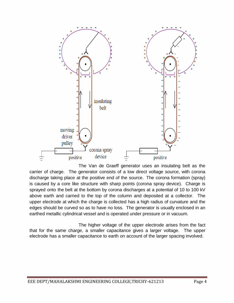
The Van de Graeff generator uses an insulating belt as the
carrier of charge. The generator consists of a low direct voltage source, with corona
discharge taking place at the positive end of the source. The corona formation (spray)
is caused by a core like structure with sharp points (corona spray device). Charge is
sprayed onto the belt at the bottom by corona discharges at a potential of 10 to 100 kV
above earth and carried to the top of the column and deposited at a collector. The
upper electrode at which the charge is collected has a high radius of curvature and the
edges should be curved so as to have no loss. The generator is usually enclosed in an
earthed metallic cylindrical vessel and is operated under pressure or in vacuum.
The higher voltage of the upper electrode arises from the fact
that for the same charge, a smaller capacitance gives a larger voltage. The upper
electrode has a smaller capacitance to earth on account of the larger spacing involved.

EEE DEPT/MAHALAKSHMI ENGINEERING COLLEGE,TRICHY-621213 Page 5
A steady potential will be reached by the high voltage
electrode when the leakage currents na the load current are equal to the charging
current. The edges of the upper electrode are so rounded as to avoid corona and other
local discharges.
With a single source at the lower end, the belt moves
upwards with a positive charge and returns uncharged. Charging can be made more
effective by having an additional charge of opposite polarity sprayed onto the belt by a
self inducing arrangement (negative corona spray).using an ingenious method.this
arrangement effectively doubles the charging rate.
2.Explain the generation of high direct voltages and voltage multiplier circuits?
Generation of high direct voltages are required in the testing
of high voltage direct current apparatus as well as in testing the insulation of cables and
capacitors where the use of alternating voltage test sets become impractical due to the
steady high charging currents. Impulse generator charging units also require high
direct voltages as their input.

EEE DEPT/MAHALAKSHMI ENGINEERING COLLEGE,TRICHY-621213 Page 6
One of the simplest methods of producing high
direct voltages for testing is to use either a half-wave for full- wave rectifier circuit with a
high alternating voltage source. The rectifiers used must be high voltage rectifiers with
a peak inverse voltage of at least twice the peak value of the alternating voltage supply.
In theory, a low pass filter may be used to smooth the output, however when the test
device is highly capacitive no smoothing is required. Even otherwise only a
capacitance may be used across the test device for smoothing. Figure 7.7 shows
the half-wave and the full wave arrangements.
In testing with high voltage direct current care must be
taken to discharge any capacitors that may be present before changing connections.In
certain test sets, automatic discharging is provided which discharges the capacitors to
earth.
Voltage Multiplier circuits :
Both full-wave as well as half-wave circuits can produce a
maximum direct voltage corresponding to the peak value of the alternating voltage.
When higher voltages are required voltage multiplier circuits are used. The common
circuits are the voltage double circuit and the Cockroft-Walton Circuit.

EEE DEPT/MAHALAKSHMI ENGINEERING COLLEGE,TRICHY-621213 Page 7
3.Explain the operation of impulse generator ? In order that equipment designed to be used on
high voltage lines, and others, be able to withstand surges caused in them during
operation, it is necessary to test these equipment with voltages of the form likely to be
met in service.
The apparatus which produces the required voltages is
the impulse generator. In high voltage engineering, an impulse voltage is normally a
unidirectional voltage which rises quickly without appreciable oscillations, to a peak
value and then falls less rapidly to zero. A full impulse wave is one which
develops its complete waveshape without flashover or puncture, whereas a chopped
wave is one in which flash-over occurs causing the voltage to fall extremely rapidly. The
rapid fall may have a very severe effect on power system equipment.
The lightning waveform, is a unidirectional impulse
of nearly double exponential in shape. That is, it can be represented by the difference
of two equal magnitude exponentially decaying waveforms. In generating such
waveforms experimentally, small oscillations are tolerated. Figure 8.1 shows the

EEE DEPT/MAHALAKSHMI ENGINEERING COLLEGE,TRICHY-621213 Page 8
graphical construction of the double exponential waveform
In most impulse generators, certain capacitors are
charged in parallel through high series resistances, and then discharged through a
combination of resistors and capacitors, giving rise to the required surge waveform
across the test device.
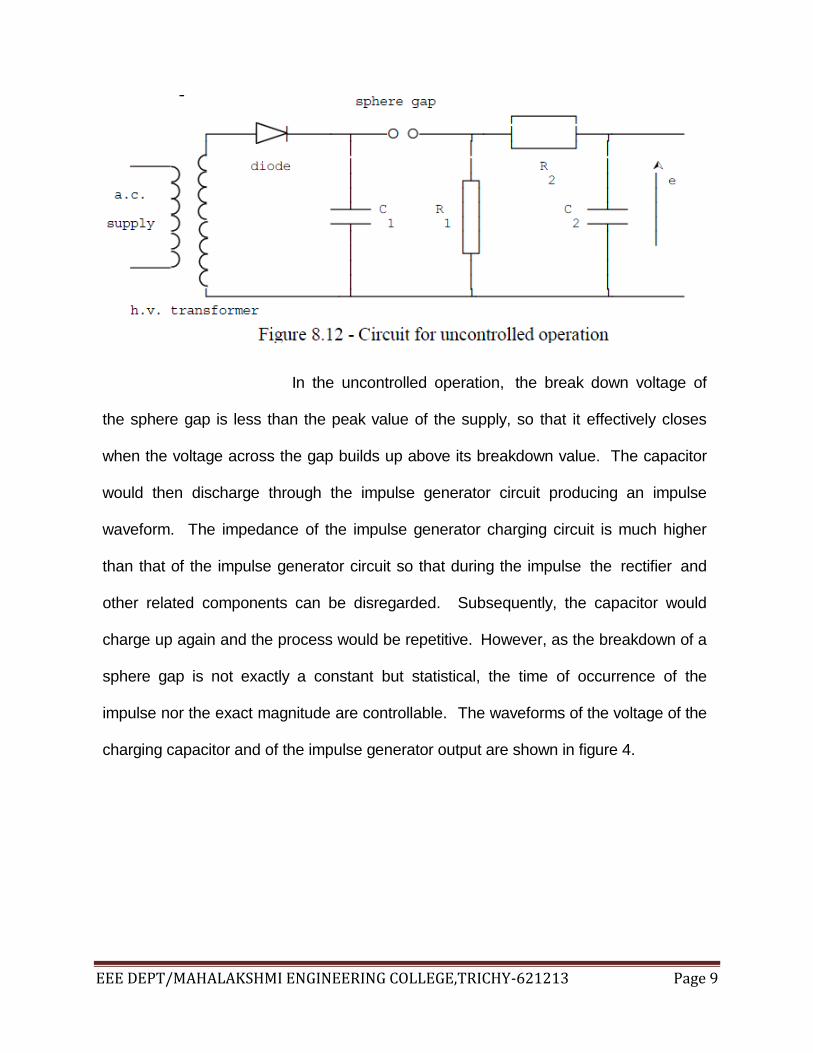
Operation of impulse generator: uncontrolled operation: In the simplest form of the single stage impulse generator, shown in figure 8.12, the high
direct voltage required is obtained from a high voltage transformer through a high voltage
rectifier. The direct voltage need not be smooth as it only has to charge the first
capacitor to peak value. A sphere gap is used as the switch, and as the charge on the
capacitor builds up, so does the voltage across the sphere gap
EEE DEPT/MAHALAKSHMI ENGINEERING COLLEGE,TRICHY-621213 Page 9
In the uncontrolled operation, the break down voltage of
the sphere gap is less than the peak value of the supply, so that it effectively closes
when the voltage across the gap builds up above its breakdown value. The capacitor
would then discharge through the impulse generator circuit producing an impulse
waveform. The impedance of the impulse generator charging circuit is much higher
than that of the impulse generator circuit so that during the impulse the rectifier and
other related components can be disregarded. Subsequently, the capacitor would
charge up again and the process would be repetitive. However, as the breakdown of a
sphere gap is not exactly a constant but statistical, the time of occurrence of the
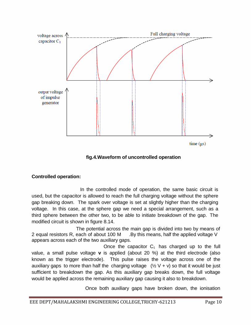
impulse nor the exact magnitude are controllable. The waveforms of the voltage of the
charging capacitor and of the impulse generator output are shown in figure 4.
EEE DEPT/MAHALAKSHMI ENGINEERING COLLEGE,TRICHY-621213 Page 10
fig.4.Waveform of uncontrolled operation
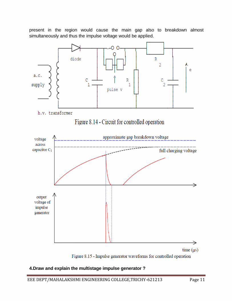
Controlled operation:
In the controlled mode of operation, the same basic circuit is
used, but the capacitor is allowed to reach the full charging voltage without the sphere
gap breaking down. The spark over voltage is set at slightly higher than the charging
voltage. In this case, at the sphere gap we need a special arrangement, such as a
third sphere between the other two, to be able to initiate breakdown of the gap. The
modified circuit is shown in figure 8.14.
The potential across the main gap is divided into two by means of 2 equal resistors R, each of about 100 M .By this means, half the applied voltage V appears across each of the two auxiliary gaps.
Once the capacitor C1 has charged up to the full
value, a small pulse voltage v is applied (about 20 %) at the third electrode (also
known as the trigger electrode). This pulse raises the voltage across one of the
auxiliary gaps to more than half the charging voltage (½ V + v) so that it would be just
sufficient to breakdown the gap. As this auxiliary gap breaks down, the full voltage
would be applied across the remaining auxiliary gap causing it also to breakdown.
Once both auxiliary gaps have broken down, the ionisation
EEE DEPT/MAHALAKSHMI ENGINEERING COLLEGE,TRICHY-621213 Page 11
present in the region would cause the main gap also to breakdown almost
simultaneously and thus the impulse voltage would be applied.
4.Draw and explain the multistage impulse generator ?

EEE DEPT/MAHALAKSHMI ENGINEERING COLLEGE,TRICHY-621213 Page 12
To obtain large impulse voltages, a multistage impulse generator is
used so that the relative size of the high voltage transformer can be kept small, and the
costs small. The basic idea is to charge a number of capacitors in parallel through a
rectifier from a high voltage transformer and then to discharge them in series, giving
the nominal output voltage equal to the charging voltage multiplied by the number
of stages in the impulse generator.
In the practical circuit, the capacitors are not all charged to
the same voltage, due to the resistances that come in series during charging being not
negligible compared to the leakage resistances of the capacitors (especially when the
number of stages are large). In theory, the number of gaps and the capacitors may be
increased to give almost any desired multiple of the charging voltage and it has been
found feasible in practice to operate a 50 stage impulse generator. The number which
can be used successfully is limited to some extent, however, by the fact that the high
resistance between the supply and the distant capacitors reduce the impulse voltage
obtainable.
Two of the commonly used impulse generator circuits are
shown. However, as the principles involved are similar only one will be described.
Max impulse generator circuit:
Marx was the first to propose that multistage impulse generators can be obtained by charging the capacitors in parallel and then connecting them in series for discharging.
In the circuit shown in figure 8.17, the resistances R are

EEE DEPT/MAHALAKSHMI ENGINEERING COLLEGE,TRICHY-621213 Page 13
the charging resistors which are very high in value, and selected such that charging of
all capacitors occurs in about 1 minute. The wave shaping circuit is external to the
capacitor stages shown. The waveform of the surge generated depends on the
resistance, inductance and capacitance of the testing circuit connected. In the modified
Marx circuit is more common use, the part of the charging resistors are made use of for
waveshape control.
Goodlet impulse generator circuit:
The Good let impulse generator circuit is very similar to the
Marx impulse generator circuit except that the Good let circuit gives a negative polarity
output for a positive polarity input while the Marx circuit gives the same polarity
output.
Since all the gaps in the impulse generator should be of

EEE DEPT/MAHALAKSHMI ENGINEERING COLLEGE,TRICHY-621213 Page 14
almost the same spacing, if they are to breakdown in succession, the spheres of the
gaps are fixed along an insulating rod which can be rotated so that the gaps
simultaneously increase or decrease as required.
In the case of a controlled impulse generator, the magnitude of
the impulse voltage is not directly dependant on the gap spacing as in the case of
uncontrolled generators. In this case, a certain range of impulse voltages are available
for the same gap spacing. This range is determined by the conditions that (a)
uncontrolled operation should not occur, (i.e. the spark over voltage of the gaps must
be greater than the applied direct voltage), and (b) the spark over voltage must not be
very much larger than the applied voltage (in which case breakdown cannot be
initiated even with the pulse).
Simultaneous breakdown of sucessive sphere gaps:
The resistance and capacitance units are arranged so

EEE DEPT/MAHALAKSHMI ENGINEERING COLLEGE,TRICHY-621213 Page 15
that the sphere gaps are placed one above the other. The capacitors are placed in
either two or 4 parallel columns, and the resistances are arranged in a diagonal
manner, as shown. The capacitors are mounted vertically above each other with
layers of insulation separating them. This arrangement is shown in figure 8.19, without
the waveshape control elements.
Once the initial pulse breaks down the first gap,
the breakdown of the successive gaps occurs in the following manner. If the supply voltage is +V, under steady charged
condition and before the breakdown of the gaps, the voltage across each capacitor will
be V, assuming the leakage across the capacitors is negligible. When the trigger pulse is applied, the breakdown of
the trigger electrode and hence of the first gap occurs, and the voltage across it falls to
zero (disregarding the arc voltage drop). As the voltage across the capacitor C1
cannot change instantly, the voltage at a must fall to -V from 0. Due to the initial
voltage +V at b, which also occurs across the stray capacitance to earth at b, and
since this stray capacitance too cannot discharge suddenly, the voltage at b must
remain at +V. Thus a voltage of +2V must appear across the second gap ab. This
voltage is sufficient to breakdown the gap (as the settings of the gaps are so arranged),
and thus the gap breaks down. This breakdown causes the voltage at b to change to
that at a (i.e. to -V). Since C2 does not discharge suddenly, the voltage at c falls to -
2V. The voltage at d would remain at +V which value it would have reached when b
became +V. Thus the voltage of 3V across the third gap breaks it down. Similarly,
any other gaps present would breakdown in succession.
Effect of sphere gap capacitances on the successive breakdown: In the above analysis, the sphere gaps are assumed
to be large and the stray capacitances across the gaps have been neglected.
However, when the voltage of the impulse generator is increased, the gaps further. In
this case we must also take the gap capacitance into account. Figure 8.20 shows the
impulse generator circuit with the stray capacitances also indicated, and with C1 = C2 =
C3 = C.

EEE DEPT/MAHALAKSHMI ENGINEERING COLLEGE,TRICHY-621213 Page 16
If the gap is large, c2 = 0, and the voltage across the second
EEE DEPT/MAHALAKSHMI ENGINEERING COLLEGE,TRICHY-621213 Page 17
sphere gap is 2V, which is the ideal case, since this ensures the breakdown of
successive gaps.
On the other hand, if c1 + c3 is small compared to c2, then the
voltage across the second sphere gap is approximately equal to V, so that the
breakdown of successive gaps would not occur. Therefore, for good operating
conditions, c1 + c3 must be large, and c2 small, so that the upper
gaps would breakdown simultaneously.
Generally, for a small impulse generator, since the sphere
gap is small, c2 is high and c1 + c3 small, so that the conditions for the breakdown of
successive gaps is poor. In this case, c1 can be deliberately increased to improve
breakdown conditions. In the case of large impulse generators, c2 is small, so that the
conditions are favorable for the breakdown of the upper gaps.
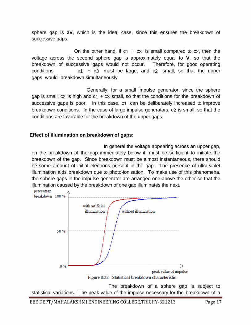
Effect of illumination on breakdown of gaps: In general the voltage appearing across an upper gap,
on the breakdown of the gap immediately below it, must be sufficient to initiate the
breakdown of the gap. Since breakdown must be almost instantaneous, there should
be some amount of initial electrons present in the gap. The presence of ultra-violet
illumination aids breakdown due to photo-ionisation. To make use of this phenomena,
the sphere gaps in the impulse generator are arranged one above the other so that the
illumination caused by the breakdown of one gap illuminates the next.
The breakdown of a sphere gap is subject to
statistical variations. The peak value of the impulse necessary for the breakdown of a

EEE DEPT/MAHALAKSHMI ENGINEERING COLLEGE,TRICHY-621213 Page 18
gap may vary over a small range, as shown in figure 8.22. If artificial illumination is
provided at the gap (as with the ultra violet radiation from the breakdown of the previous
gap), the uncertainty of the breakdown for a particular gap setting is reduced. This
is due to the fact that a certain amount of electrons/second are created by phot-
ionisation in the gap, and the breakdown is more constant.
Due to the presence of stray capacitances etc, the
order of the differential equation governing the impulse waveform is increased, and the
practical circuit will have exponential terms to the order of the number of storage
elements.

EEE DEPT/MAHALAKSHMI ENGINEERING COLLEGE,TRICHY-621213 Page 19
5.Draw the multistage impulse current generator circuit .Explain its operation and applications ?

EEE DEPT/MAHALAKSHMI ENGINEERING COLLEGE,TRICHY-621213 Page 20
6.Write a brief note on resonant transformer method ?

EEE DEPT/MAHALAKSHMI ENGINEERING COLLEGE,TRICHY-621213 Page 21