
Engineering Asset Identification
38
WORK INSTRUCTION WI5.14.4 Engineering Asset Identification Responsible Executive: General Manager Asset Management Date of issue: 14 November 2014 Version: 1 Next review date: 14 November 2016 WI5.14.4 Date of issue: 14 November 2014 Page 1 of 38 1 Purpose .................................................................................................................................................... 3 2 Scope ........................................................................................................................................................ 3 3 Roles and Responsibilities .................................................................................................................... 3 4 Hierarchical Levels ................................................................................................................................. 4 4.1 EAR – Level 1 and Level 2 ................................................................................................................ 4 4.1.1 Level 1 – Functional System ......................................................................................................... 4 4.1.2 Level 2 – Facility Type ................................................................................................................... 4 4.2 EAR Complex Facilities ..................................................................................................................... 4 4.2.1 Level 3 – Facility (Complex Facilities) ......................................................................................... 5 4.2.2 Level 4 – Facility Main Process (Complex Facilities) ................................................................ 5 4.2.3 Level 5 – Facility Sub-Process (Complex Facilities) ................................................................. 5 4.2.4 Level 6 – Equipment Location (Complex Facilities) .................................................................. 6 4.2.5 Level 7 – Unit Location (Complex Facilities) .............................................................................. 7 4.2.6 Level 6 – Instrument Loop (Complex Facilities) ......................................................................... 8 4.2.7 Level 7 – Instrument Location (Complex Facilities) ................................................................... 9 4.2.8 Level 6 – Valve Location – Manual (Complex Facilities) ........................................................ 10 4.2.9 Level 6 – Dam Structure Monitoring Location (Complex Facilities) ...................................... 11 4.2.10 Pipe Identification.......................................................................................................................... 11 4.3 EAR Simple Facilities ....................................................................................................................... 12 4.3.1 Level 3 – Facility (Simple Facilities) ........................................................................................... 12 4.3.2 Level 4 – Equipment Location (Simple Facilities) .................................................................... 12 4.3.3 Level 5 – Unit Location (Simple Facilities) ................................................................................ 13 4.3.4 Level 4 – Instrument Loop (Simple Facilities) .......................................................................... 15 4.3.5 Level 5 – Instrument Location (Simple Facilities) .................................................................... 15 4.3.6 Valve Location – Manual (Simple Facilities) ............................................................................. 17 4.4 Units and Instruments ...................................................................................................................... 18 4.4.1 Units (Complex and Simple Facilities) ....................................................................................... 18 4.4.2 Instruments (Complex and Simple Facilities) ........................................................................... 19 4.5 Hierarchical Relationships for Units and Instruments ................................................................. 20 4.5.1 Common Scenarios ...................................................................................................................... 20
Transcript of Engineering Asset Identification

WORK INSTRUCTION WI5.14.4
Engineering Asset Identification
Responsible Executive: General Manager Asset Management
Date of issue: 14 November 2014 Version: 1 Next review date: 14 November 2016
WI5.14.4 Date of issue: 14 November 2014 Page 1 of 38
1 Purpose .................................................................................................................................................... 3
2 Scope ........................................................................................................................................................ 3
3 Roles and Responsibilities .................................................................................................................... 3
4 Hierarchical Levels ................................................................................................................................. 4
4.1 EAR – Level 1 and Level 2 ................................................................................................................ 4
4.1.1 Level 1 – Functional System ......................................................................................................... 4
4.1.2 Level 2 – Facility Type ................................................................................................................... 4
4.2 EAR Complex Facilities ..................................................................................................................... 4
4.2.1 Level 3 – Facility (Complex Facilities) ......................................................................................... 5
4.2.2 Level 4 – Facility Main Process (Complex Facilities) ................................................................ 5
4.2.3 Level 5 – Facility Sub-Process (Complex Facilities) ................................................................. 5
4.2.4 Level 6 – Equipment Location (Complex Facilities) .................................................................. 6
4.2.5 Level 7 – Unit Location (Complex Facilities) .............................................................................. 7
4.2.6 Level 6 – Instrument Loop (Complex Facilities) ......................................................................... 8
4.2.7 Level 7 – Instrument Location (Complex Facilities) ................................................................... 9
4.2.8 Level 6 – Valve Location – Manual (Complex Facilities) ........................................................ 10
4.2.9 Level 6 – Dam Structure Monitoring Location (Complex Facilities) ...................................... 11
4.2.10 Pipe Identification .......................................................................................................................... 11
4.3 EAR Simple Facilities ....................................................................................................................... 12
4.3.1 Level 3 – Facility (Simple Facilities) ........................................................................................... 12
4.3.2 Level 4 – Equipment Location (Simple Facilities) .................................................................... 12
4.3.3 Level 5 – Unit Location (Simple Facilities) ................................................................................ 13
4.3.4 Level 4 – Instrument Loop (Simple Facilities) .......................................................................... 15
4.3.5 Level 5 – Instrument Location (Simple Facilities) .................................................................... 15
4.3.6 Valve Location – Manual (Simple Facilities) ............................................................................. 17
4.4 Units and Instruments ...................................................................................................................... 18
4.4.1 Units (Complex and Simple Facilities) ....................................................................................... 18
4.4.2 Instruments (Complex and Simple Facilities) ........................................................................... 19
4.5 Hierarchical Relationships for Units and Instruments ................................................................. 20
4.5.1 Common Scenarios ...................................................................................................................... 20
WORK INSTRUCTION WI5.14.4
Engineering Asset Identification
Responsible Executive: General Manager Asset Management
Date of issue: 14 November 2014 Version: 1 Next review date: 14 November 2016
WI5.14.4 Date of issue: 14 November 2014 Page 2 of 38
4.5.2 Instrument not Part of an Instrument Loop ............................................................................... 20
4.5.3 Unit with Integral Instrument ....................................................................................................... 21
4.5.4 Unit that Supports an Instrument Loop ...................................................................................... 21
5 Field Labelling Requirements ............................................................................................................. 21
5.1 Labelling Requirements – Equipment Locations / Dam Structure Monitoring Locations ....... 22
5.2 Labelling Requirements – Unit Locations ..................................................................................... 22
5.3 Labelling Requirements – Instrument Loops ................................................................................ 23
5.4 Labelling Requirements – Instrument Locations .......................................................................... 24
5.5 Labelling Requirements – Valve Locations – Manual ................................................................. 24
5.6 Labelling Requirements – Piping Systems ................................................................................... 25
5.7 Labelling Requirements – Units / Instruments ............................................................................. 25
6 Related Documents .............................................................................................................................. 27
7 References ............................................................................................................................................. 27
8 Definitions .............................................................................................................................................. 27
9 Tables ..................................................................................................................................................... 27
9.1 Facility Types and Classifications .................................................................................................. 27
9.2 Complex Facility Types and Facilities ........................................................................................... 28
9.3 Simple Facility Types ....................................................................................................................... 28
9.4 Equipment Type Suffix ..................................................................................................................... 29
9.5 Unit Location Suffix ........................................................................................................................... 30
9.6 Unit Sub-types ................................................................................................................................... 32
9.7 Instrument Location Suffix ............................................................................................................... 36
9.8 Instrument Variable .......................................................................................................................... 37
9.9 Instrument Type ................................................................................................................................ 38
9.10 Instrument Sub-type ......................................................................................................................... 38

WORK INSTRUCTION WI5.14.4
Engineering Asset Identification
Responsible Executive: General Manager Asset Management
Date of issue: 14 November 2014 Version: 1 Next review date: 14 November 2016
WI5.14.4 Date of issue: 14 November 2014 Page 3 of 38
1 Purpose
The purpose of this document is to define the structure of the Engineering Asset Register (EAR) and
associated asset coding / naming convention. Assets will be referenced in the EAR under a range of
hierarchical levels designed to provide aggregated information for monitoring, reporting and decision making.
The EAR will also be used to provide a user friendly structure to facilitate the navigation of asset information
systems.
A full listing of the EAR is detailed in the corporate asset management system.
2 Scope
This Work Instruction shall apply to all water supply and sewerage assets owned and managed by ACTEW
Water except for Minor Non-system Assets (MNSA).
3 Roles and Responsibilities
Manager Asset Management
Custodian of this document.
Ensuring the correct and consistent application of this Work Instruction.
Asset Data Coordinator
Maintenance of this document.
Determining and specifying structural updates to the asset hierarchy (in conjunction with Water and
Sewer asset managers) when new assets are acquired / built and when existing assets are modified.
Updating EAR data in the corporate asset management system as a result of CAPEX (all assets)
and maintenance activities (all assets except for Instrumentation).
Works Co-ordinator Instrumentation
Updating EAR data in the corporate asset management system as a result of maintenance activities
for instrumentation.

WORK INSTRUCTION WI5.14.4
Engineering Asset Identification
Responsible Executive: General Manager Asset Management
Date of issue: 14 November 2014 Version: 1 Next review date: 14 November 2016
WI5.14.4 Date of issue: 14 November 2014 Page 4 of 38
4 Hierarchical Levels
4.1 EAR – Level 1 and Level 2
The EAR is categorised into different hierarchical levels. The first two levels (Level 1 and Level 2) are
common across all Facility Types and are defined in the remainder of this sub-section.
4.1.1 Level 1 – Functional System
Level 1 (Functional System) is defined as a group of assets having a similar nature and function in ACTEW’s
Water Business. Each Functional System has an alpha code and a description. The codes and associated
descriptions are:
o SNET – Sewer Network
o WNET – Water Network
o RNET – Reclaimed Water Network
4.1.2 Level 2 – Facility Type
Level 2 (Facility Type) is defined as a group of assets having similar characteristics for service delivery within
the Level 1 classifications. Each Facility Type has an alpha code and a description. The codes and
associated descriptions are detailed in 9.1 Facility Types and Classifications.
The remaining levels in the EAR (Level 3 down) are dependent on whether the Facility Type is classified as
a Simple Facility or Complex Facility.
Simple Facilities are facility types that comprise a relatively small number of children assets and / or children
assets that are within a confined geographical area. Complex Facilities are facility types that comprise a
relatively large number of children assets and / or children assets that are not within a confined geographical
area. Simple Facility Types and Complex Facilities are detailed in 9.3 Simple Facility Types and 9.2
Complex Facility Types and Facilities.
The hierarchical structure of Complex and Simple Facilities are defined in Section 4.2 EAR Complex
Facilities and Section 4.3 EAR Simple Facilities respectively.
4.2 EAR Complex Facilities
Complex Facilities consist of a further 6 levels below Level 2 (Facility Type) as defined below:
o Level 3 (Facility)
o Level 4 (Facility Main Process)
o Level 5 (Facility Sub-Process)
o Level 6 (Equipment Location, Instrument Loop or Valve Location - Manual)
o Level 7 (Unit Location or Instrument Location)
o Level 8 (Unit or Instrument)

WORK INSTRUCTION WI5.14.4
Engineering Asset Identification
Responsible Executive: General Manager Asset Management
Date of issue: 14 November 2014 Version: 1 Next review date: 14 November 2016
WI5.14.4 Date of issue: 14 November 2014 Page 5 of 38
These levels of the EAR for Complex Facilities (including associated asset coding and naming conventions)
are further defined in the remainder of this sub-section except for Level 8 (Unit or Instrument) which is
described in 4.4 Units and Instruments.
4.2.1 Level 3 – Facility (Complex Facilities)
Level 3 (Facility) consists of the individual facilities within the Level 2 (Facility Type) classifications. Each
Facility has an alpha code and an associated description. Complex Facilities are detailed in 9.2 Complex
Facility Types and Facilities.
4.2.2 Level 4 – Facility Main Process (Complex Facilities)
Each Level 3 (Facility) is divided into one or more Level 4 (Facility Main Processes). A Facility Main Process
delivers a discrete process output within a specific Facility. Each Facility Main Process has an alphanumeric
code and an associated description.
The format of the Facility Main Process code is:
AAABB
Where:
AAA is a 3 character Facility Code representing the Facility (as detailed in 9.2 Complex Facility Types and
Facilities).
BB is a 2 character code representing the Facility Main Process.
The naming convention for the description of Facility Main Processes is a description of the discrete process
output that it delivers.
Examples of Facility Main Processes (codes and descriptions) at LMWQCC Sewage Treatment Plant
include:
SLMSM – Solids Management
SLM1T – Primary Treatment
A full listing of Facility Main Processes is detailed in the corporate asset management system.
4.2.3 Level 5 – Facility Sub-Process (Complex Facilities)
Each Level 4 (Facility Main Process) is divided into one or more Level 5 (Facility Sub-Processes). A Facility
Sub-Process delivers a discrete process output within a specific Facility Main Process. Each Facility Sub-
Process has an alphanumeric code and an associated description.
The format of the Facility Sub-Process code is:
AAABBCCC
Where:
AAA is a 3 character Facility Code representing the Facility (as detailed in 9.2 Complex Facility Types and
Facilities).

WORK INSTRUCTION WI5.14.4
Engineering Asset Identification
Responsible Executive: General Manager Asset Management
Date of issue: 14 November 2014 Version: 1 Next review date: 14 November 2016
WI5.14.4 Date of issue: 14 November 2014 Page 6 of 38
BB is a 2 character code representing the Facility Main Process.
CCC is a 3 character code representing the Facility Sub-Process.
The naming convention for the description of Facility Sub-Processes is a description of the discrete process
output that it delivers.
Examples of Facility Sub-Processes (codes and descriptions) include:
SLMSMASD – Ash Handling and Disposal
SLM1TPC1 – Primary Clarification Unit 1
A full listing of Facility Sub-Processes is detailed in the corporate asset management system.
4.2.4 Level 6 – Equipment Location (Complex Facilities)
Level 6 can either be an Equipment Location, Instrument Loop, Valve Location – Manual or Dam Structure
Monitoring Location. Instrument Loops are defined in sub-section 4.2.6 Level 6 – Instrument Loop (Complex
Facilities). Valve Location – Manual is defined at 4.2.8 Level 6 – Valve Location – Manual (Complex
Facilities). Dam Structure Monitoring Location is defined at 4.2.9 Level 6 – Dam Structure Monitoring
Location (Complex Facilities).
Level 6 (Equipment Location) consists of the locations of functional systems that are part of each Facility
Sub-Process. Each Equipment Location has an alphanumeric code and an associated description. This code
and description are used when identifying the asset in the corporate asset management system,
documentation, field labels and on drawings.
The format of the Equipment Location code is:
AA[A]-BBCC[C]DD
Where:
AA[A] is a 2 or 3 character Plant Code. The Plant Code represents the Facility at which the Equipment
Location is located (as detailed in 9.2 Complex Facility Types and Facilities). Note this is different to
the Facility Code which is always a 3 character code.
BB is a 2 digit numeric code representing the Structure and Area number defined at each Complex
Facility (see relevant Structure and Area Number document at 7 References).
CC[C] is a 2 or 3 digit sequential number that uniquely identifies an Equipment Location within a Structure
and Area of a Complex Facility. Where the full range of two digit numbers have been consumed for
a Structure and Area then three digit numbers commencing at 101 are used. Sequential numbers
containing more than one zero are reserved for the identification of major structures.

WORK INSTRUCTION WI5.14.4
Engineering Asset Identification
Responsible Executive: General Manager Asset Management
Date of issue: 14 November 2014 Version: 1 Next review date: 14 November 2016
WI5.14.4 Date of issue: 14 November 2014 Page 7 of 38
DD is a 2 character Equipment Type code that represents the function of the Equipment Location (e.g.
Pump, Mixer etc. as detailed in 9.4 Equipment Type Suffix).
The naming convention for the description is the basic function performed by the Equipment Location.
Examples of Equipment Locations (codes and descriptions) include:
WG-2114MV – Filter Drain Penstock
LM-34103PU – Biological Reactor 1 MLR Pump 3
A full listing of Equipment Locations is detailed in the corporate asset management system.
Note 1: In the case of solenoid valves which are not directly associated with a single Equipment Location or
are common to multiple Equipment Locations, the solenoid valve will be identified by an Equipment Location
of its own.
In the case of solenoid valves which are directly associated with one equipment item and located at that
equipment item then they will be identified as a Unit Location (see 4.2.5 Level 7 – Unit Location (Complex
Facilities)) of the Equipment Location number it’s accosoated with.
4.2.5 Level 7 – Unit Location (Complex Facilities)
Level 7 can either be a Unit Location or Instrument Location. Instrument Locations are defined in sub-
section 4.2.7 Level 7 – Instrument Location (Complex Facilities).
Level 7 (Unit Location) consists of the location of functional components that make up each Equipment
Location. For example a motor function of a pump gearbox motor set. Each Unit Location has an
alphanumeric code and an associated description.
The format of the Unit Location code is:
EQLO-EEE[FF]
Where:
EQLO is the code representing the Equipment Location (as detailed in Section 4.2.4 Level 6 – Equipment
Location (Complex Facilities)).
EEE is a 3 character code representing the Unit Type (as detailed in 9.5 Unit Location Suffix).
[FF] is a two digit sequential number which is unique and necessary only to distinguish Unit Locations of
the same type with in a given Equipment Location.
The format of the Unit Location description is:
W; X | Y
Where:

WORK INSTRUCTION WI5.14.4
Engineering Asset Identification
Responsible Executive: General Manager Asset Management
Date of issue: 14 November 2014 Version: 1 Next review date: 14 November 2016
WI5.14.4 Date of issue: 14 November 2014 Page 8 of 38
W is the description representing the Equipment Location (see Section 4.2.4 Level 6 –
Equipment Location (Complex Facilities) for standards related to describing an Equipment
Location).
X is the description representing the Unit (see Section 4.4.1 Units (Complex and Simple
Facilities) for standards related to describing a Unit).
Y is a descriptor which is unique and necessary only to distinguish Unit Locations of the same
type within a given Equipment Location.
Examples of Unit Locations (codes and descriptions) include:
LM-1149MV-MTR – Hearth Ash Removal Rotary Valve; Motor
LM-1526CE-MTR2 – DS706 Centrifuge 1; Motor | Back Drive
A full listing of Unit Locations is detailed in the corporate asset management system.
4.2.6 Level 6 – Instrument Loop (Complex Facilities)
Level 6 (Instrument Loop) consists of the locations of instrument loops that are part of each Facility Sub-
process. Each Instrument Loop has an alphanumeric code and an associated description. This code and
description are used when identifying the asset in the corporate asset management system, documentation,
field labels and on drawings.
The format of the Instrument Loop code is:
AA[A]-ILBBCC[C]
Where:
AA[A] is a 2 or 3 character Plant Code representing the Facility at which the Equipment Location is located
(as detailed in 9.2 Complex Facility Types and Facilities). Note this is different to the Facility Code
which is a 3 character code.
IL is an identifier denoting the term Instrument Loop.
BB is a 2 digit numeric code representing the Structure number and the Instrument Loop function related
to that structure (see relevant Structure and Area Number document at 7 References).
CC[C] is a 2 or 3 digit sequential number that uniquely identifies an Instrument Loop within a Structure
and Area of a Complex Facility. Where the full range of two digit numbers have been consumed for
a Structure and Area then three digit numbers commencing at 101 are used. Sequential numbers
containing more than one zero are not used for Instrumentation assets (e.g. IL3900, IL39100,
IL39200 etc. are not used to represent Instrument Loops).
The naming convention for the description is the basic function performed by the Instrument Loop.

WORK INSTRUCTION WI5.14.4
Engineering Asset Identification
Responsible Executive: General Manager Asset Management
Date of issue: 14 November 2014 Version: 1 Next review date: 14 November 2016
WI5.14.4 Date of issue: 14 November 2014 Page 9 of 38
Examples of Instrument Loops (codes and descriptions) at LMWQCC Sewage Treatment Plant include:
LM-IL1098 – Inert Ash Blower Pressure
LM-IL3904 – Primary Clarifier 1 Level
A full listing of Instrument Loops is detailed in the corporate asset management system.
4.2.7 Level 7 – Instrument Location (Complex Facilities)
Level 6 (Instrument Locations) consist of the locations of functional instruments that are part of each
Instrument Loop. Each Instrument Loop has an alphanumeric code and an associated description.
The format of the Instrument Location code is:
INLP-DD[DD]
Where:
INLP is the code representing the Instrument Loop (as detailed in 4.2.6 Level 6 – Instrument Loop
(Complex Facilities)).
DD[DD] is a 2 to 4 character code representing the Instrument Type and Modifier(s) (where
applicable) as detailed in 9.7 Instrument Location Suffix. Where a modifier is required, the number
of characters attributed specifically to the Modifier will be constrained as the total number of
characters permissible for an Instrument Location code is 15 characters.
For example the Instrument Location LM-IL1021-FIT:
FIT Indentifies a flow indicating transmitter as an Instrument Location of Instrument Loop
LM-IL1021.
Three characters have been used to identify the Instrument Type and there is no need to use a modifier.
The total number of characters in this code is 13.
If Instrument Loop LM-IL1021 contained two flow indicators then the Instrument Locations would be
LM-IL1021-FI01 and LM-IL1021-FI02. Two characters have been used to represent the Instrument Type (FI)
and two digits have been used to represent the Modifier (01 for Flow Indicator 1 and 02 for Flow Indicator 2).
The total number of characters in both codes is 14.
WORK INSTRUCTION WI5.14.4
Engineering Asset Identification
Responsible Executive: General Manager Asset Management
Date of issue: 14 November 2014 Version: 1 Next review date: 14 November 2016
WI5.14.4 Date of issue: 14 November 2014 Page 10 of 38
The format of the Instrument Location description is:
W; X Y
Where:
W is the description representing the Instrument Loop (see Section 4.2.6 Level 6 – Instrument
Loop (Complex Facilities) for standards related to describing an Instrument Loop).
X is the description representing the Instrument (see Section 4.4.2 Instruments (Complex and
Simple Facilities) for standards related to describing an Instrument).
Y is a descriptor which is unique and necessary only to distinguish Instrument Locations of the
same type within a given Instrument Loop. This is used to describe the Modifier(s) in the
Instrument Location code.
Examples of Instrument Locations (codes and descriptions) at LMWQCC Sewage Treatment Plant include:
LM-IL1098-PSL – Inert Ash Blower Pressure; Low Pressure Alarm
LM-IL3904-LT – Primary Clarifier 1 Level; Level Transmitter
A full listing of Instrument Locations is detailed in the corporate asset management system.
4.2.8 Level 6 – Valve Location – Manual (Complex Facilities)
Is given to manual valves that are not to be identified as an Equipment Location. It will have no children (i.e.
level 6 will be the final level in the hierarchy). Each Valve Location - Manual has an alphanumeric code and
an associated description. This code and description is used when identifying the asset in the corporate
asset management system, documentation, field labels and on drawings.
The format of the Valve Location - Manual code is:
AA[A]-BCC[C]DD[D]
Where:
AA[A] is a 2 or 3 character Plant Code representing the Facility at which the Equipment Location is located
(as detailed in 9.2 Complex Facility Types and Facilities). Note this is different to the Facility Code
which is a 3 character code.
B is a 1 digit numeric code representing the Structure number where the valve is physically located
(see relevant Structure and Area Number document at 7 References).
CC[C] is a 2 or 3 digit sequential number that uniquely identifies what fliud the valve is servicing. (See
relevant fluid codes in the Process & Instrumentaion Drawings Symbol Legend document at 7
References).

WORK INSTRUCTION WI5.14.4
Engineering Asset Identification
Responsible Executive: General Manager Asset Management
Date of issue: 14 November 2014 Version: 1 Next review date: 14 November 2016
WI5.14.4 Date of issue: 14 November 2014 Page 11 of 38
DD[D] is a 2 or 3 digit sequential number that uniquely identifies a Valve Location - Manual within a
Structure and fliud code in that Structure. Where the full range of two digit numbers have been
consumed for a Structure and fluid code then three digit numbers are used.
The naming convention for the description is the basic function performed by the valve.
Examples of Valve Location - Manual (codes and descriptions) include:
LM-1CE211 – Centifuge Feed Pump 4 Diverting Valve
WG-2ASW135 – DAF 3 Dispersion Valve 3
A full listing of Valve Locations - Manual is detailed in the corporate asset management system.
Note 2: Power actuated valves (i.e. electric motor driven, hydraulic driven and valves which use solenoid
valves to control the main valve) are to be identified by Equipment Location Numbers (see 4.2.4 Level 6 –
Equipment Location (Complex Facilities)). In some circumstances manually operated valves may also be
identified by an Equipment Location number. This may be due to requirements such as future maintenance
planning or identification issues.
The decision on which numbering system will be used for identifying valves will be made by the Asset Data
Coordinator in consultation with a sewer or water group representative.
4.2.9 Level 6 – Dam Structure Monitoring Location (Complex Facilities)
Is a location reserved strictly for assets installed on dams for the purpose of monitoring. Its asset number
and permitted asset relationships will follow the same convention as an Equipment Location (Complex
Facilities) except its suffix will always be ‘DM’.
4.2.10 Pipe Identification
Pipes are to be identified in work executed drawings.
The format of the piping identification code is:
AAABB[B]
Where:
AAA is the nominal diameter of the pipe.
BB[B] is a 2 or 3 digit sequential number that uniquely identifies what fliud the pipe is servicing. (See
relevant fluid codes in the Process & Instrumentaion Drawings Symbol Legend document at 7
References).

WORK INSTRUCTION WI5.14.4
Engineering Asset Identification
Responsible Executive: General Manager Asset Management
Date of issue: 14 November 2014 Version: 1 Next review date: 14 November 2016
WI5.14.4 Date of issue: 14 November 2014 Page 12 of 38
Examples of piping identification codes include:
250RW
125LS
4.3 EAR Simple Facilities
Simple Facilities consist of a further 4 levels below Level 2 (Facility Type) as defined below:
o Level 3 (Facility)
o Level 4 (Equipment Location, Instrument Loop or Valve Location - Manual)
o Level 5 (Unit Location or Instrument Location)
o Level 6 (Unit or Instrument)
These levels of the Asset Hierarchy for Simple Facilities are defined in the remainder of this sub-section
except for Level 6 (Unit or Instrument) which is described in 4.4 Units and Instruments.
4.3.1 Level 3 – Facility (Simple Facilities)
Level 3 (Facility) consists of the individual facilities within the Level 2 (Facility Type) classifications. Each
Facility has an alphanumeric code and an associated description.
The format of the Facility Code is:
AABBB
Where:
AA is a 2 character code representing the Simple Facility Type (as detailed in 9.3 Simple Facility
Types).
BBB is a 3 digit sequential number which is unique only within the Facility Type.
The naming convention for the description of Facilities (in general) consists of the suburb / district where the
Facility is located or the suburb / district which the Facility serves followed by the Facility Type.
Examples of Simple Facilities (codes and descriptions) include:
SP013 – Fyshwick Sewage Pump Station
WR019 – Aranda Water Reservoir
A full listing of Simple Facilities is detailed in the corporate asset management system.
4.3.2 Level 4 – Equipment Location (Simple Facilities)
Level 4 can either be an Equipment Location, Instrument Loop or Valve Location - Manual. Instrument
Loops are defined in 4.3.4 Level 4 – Instrument Loop (Simple Facilities). Valve Location – Manual is defined
in 4.3.6 Valve Location – Manual (Simple Facilities).

WORK INSTRUCTION WI5.14.4
Engineering Asset Identification
Responsible Executive: General Manager Asset Management
Date of issue: 14 November 2014 Version: 1 Next review date: 14 November 2016
WI5.14.4 Date of issue: 14 November 2014 Page 13 of 38
Level 4 (Equipment Location) consists of the locations of functional systems that are part of each Facility.
Each Equipment Location has an alphanumeric code and an associated description.
The format of the Equipment Location code is:
FAC-CCDD
Where:
FAC is the code representing the Facility of the Equipment Location (as detailed in 4.3.1 Level 3 – Facility
(Simple Facilities)).
CC is a 2 digit sequential number which is unique to both Equipment Locations and Instrument Loops
within a given Facility. Note: some existing Equipment Locations will have the same 2 digit number within the
same Simple Facility which is a legacy prior to the introduction of this standard.
DD is a 2 character Equipment Type code that represents the function of the Equipment
Location (e.g. Pump, Mixer etc. as detailed in 9.4 Equipment Type Suffix).
The format of the Equipment Location description is:
W - X
Where:
W is the Facility name
X is the basic function performed by the Equipment Location.
Examples of Equipment Locations (codes and descriptions) for Simple Facilities include:
SP013-01PU – Fyshwick Sewage Pump Station - Dry Well Pump System 1
WR019-02CP – Aranda Water Reservoir - Main Control Panel
Note that there is no relationship between the 2 digit sequential number in the code and number in the
description (e.g. 01PU will not necessarily always represent Pump System 1 in a given facility).
A full listing of Equipment Locations is detailed in the corporate asset management system.
4.3.3 Level 5 – Unit Location (Simple Facilities)
Level 5 can either be a Unit Location or Instrument Location. Instrument Locations are defined in sub-section
4.3.5 Level 5 – Instrument Location (Simple Facilities).

WORK INSTRUCTION WI5.14.4
Engineering Asset Identification
Responsible Executive: General Manager Asset Management
Date of issue: 14 November 2014 Version: 1 Next review date: 14 November 2016
WI5.14.4 Date of issue: 14 November 2014 Page 14 of 38
Level 5 (Unit Location) consists of the location of functional components that make up each Equipment
Location. Each Unit Location has an alphanumeric code and an associated description.
The format of the Unit Location code is:
EQLO-EEEF
Where:
EQLO is the code representing the Equipment Location (as detailed in Section 4.3.2 Level 4 – Equipment
Location (Simple Facilities)).
EEE is a 3 character code representing the Unit Type (as detailed in 9.5 Unit Location Suffix).
F is a single digit sequential number which is unique and necessary only to distinguish Unit Locations
of the same type within a given Equipment Location.
The format of the Unit Location description is:
W; X | Y
Where:
W is the description representing the Equipment Location (see Section 4.3.2 Level 4 –
Equipment Location (Simple Facilities) for standards related to describing an Equipment
Location).
X is the description representing the Unit (see Section 4.4.1 Units (Complex and Simple
Facilities) for standards related to describing a Unit).
Y is a descriptor which is unique and necessary only to distinguish Unit Locations of the same
type within a given Equipment Location.
Examples of Unit Locations (codes and descriptions) for Simple Facilities include:
SP013-01PU-PMP – Fyshwick Sewage Pump Station - Dry Well Pump System 1; Pump (Centrifugal)
SP033-04CP-PLC – Parkwood Sewage Pump Station - RTU Control Panel; PLC
A full listing of Unit Locations is detailed in the corporate asset management system.

WORK INSTRUCTION WI5.14.4
Engineering Asset Identification
Responsible Executive: General Manager Asset Management
Date of issue: 14 November 2014 Version: 1 Next review date: 14 November 2016
WI5.14.4 Date of issue: 14 November 2014 Page 15 of 38
4.3.4 Level 4 – Instrument Loop (Simple Facilities)
Level 4 (Instrument Loop) consists of the locations of instrument loops that are part of each Facility.
Each Instrument Loop has an alphanumeric code and an associated description.
The format of the Instrument Loop code is:
FAC-ILCC
Where:
FAC is the code representing the Facility of the Instrument Loop (as detailed in 4.3.1 Level 3 – Facility
(Simple Facilities)).
IL is the code representing the term “Instrument Loop”.
CC is a 2 digit sequential number which is unique to both Instrument Loops and Equipment Locations
within a given facility.
The format of the Instrument Loop description is:
W - X
Where:
W is the Facility name
X is the basic function performed by the Instrument Loop.
Examples of Instrument Loops (codes and descriptions) for Simple Facilities include:
SP013-IL06 – Fyshwick Sewage Pump Station - Dry Well Pump 2 Discharge Pressure
SP033-IL01 – Parkwood Sewage Pump Station - Pump Station Flow
A full listing of Instrument Loops is detailed in the corporate asset management system.
4.3.5 Level 5 – Instrument Location (Simple Facilities)
Level 5 (Instrument Location) consists of the locations of functional instruments that are part of each
Instrument Loop. Each Instrument Location has an alphanumeric code and an associated description.
The format of the Instrument Location code is:
INLP-DD[DD]

WORK INSTRUCTION WI5.14.4
Engineering Asset Identification
Responsible Executive: General Manager Asset Management
Date of issue: 14 November 2014 Version: 1 Next review date: 14 November 2016
WI5.14.4 Date of issue: 14 November 2014 Page 16 of 38
Where:
INLP is the code representing the Instrument Loop (as detailed in 4.3.4 Level 4 – Instrument Loop (Simple
Facilities)).
DD[DD] is a 2 to 4 character code representing the Instrument Type and Modifier(s) (where
applicable) as detailed in 9.7 Instrument Location Suffix. Where a Modifier is required, the number
of characters attributed specifically to the Modifier will be constrained as the total number of
characters permissible for an Instrument Location code is 15 characters.
For example the Instrument Location WP025-IL01-FT:
FT Identifies a flow transmitter as an Instrument Location of Instrument Loop WP025-
IL01.
Two characters have been used to identify the Instrument Type and there is no need to use a modifier. The
total number of characters in this code is 13.
If Instrument Loop WP025-IL01 contained two flow indicators then the Instrument Locations would be
WP025-IL01-FI01 and WP025-IL01-FI02. Two characters have been used to represent the Instrument Type
(FI) and two digits have been used to represent the Modifier (01 for Flow Indicator 1 and 02 for Flow
Indicator 2). The total number of characters in this code is 15.
The format of the Instrument Location description is:
W; X Y
Where:
W is the description representing the Instrument Loop (see 4.3.4 Level 4 – Instrument Loop (Simple
Facilities) for standards related to describing an Instrument Loop).
X is the description representing the Instrument (see 4.4.2 Instruments (Complex and Simple Facilities)
for standards related to describing an Instrument).
Y is a descriptor which is unique and necessary only to distinguish Instrument Locations of the same
type within a given Instrument Loop. This is used to describe the Modifier(s) in the Instrument
Location code.

WORK INSTRUCTION WI5.14.4
Engineering Asset Identification
Responsible Executive: General Manager Asset Management
Date of issue: 14 November 2014 Version: 1 Next review date: 14 November 2016
WI5.14.4 Date of issue: 14 November 2014 Page 17 of 38
Examples of Instrument Locations (codes and descriptions) for Simple Facilities include:
SP013-IL06-FE – Pump System 1 Flow; Flow Element (Magnetic)
WP003-IL02-PT – Black Mt Tower Water Pump Station - Pump Station Discharge Pressure; Pressure
Transmitter
A full listing of Instrument Locations is detailed in the corporate asset management system.
4.3.6 Valve Location – Manual (Simple Facilities)
Is given to manual valves that are not to be identified as an Equipment Location. It will have no children (i.e.
level 4 will be the final level in the hierarchy). Each Valve Location - Manual has an alphanumeric code and
an associated description. This code and description are used when identifying the asset in the corporate
asset management system, documentation, field labels and on drawings.
The format of the Valve Location - Manual code is:
FAC-BCC[C]DD[D]
Where:
FAC is the code representing the Facility of the Equipment Location (as detailed in 4.3.1 Level 3 – Facility
(Simple Facilities)).
B is a 1 digit numeric code representing the Structure number where the valve is physically located
(see relevant Structure and Area Number document at 7 References).
CC[C] is a 2 or 3 digit sequential number that uniquely identifies what fliud the valve is servicing. (See
relevant fluid codes in the Process & Instrumentaion Drawings Symbol Legend document at 7 References).
DD[D] is a 2 or 3 digit sequential number that uniquely identifies a Valve Location - Manual within a
Structure and fliud code in that Structure. Where the full range of two digit numbers have been consumed for
a Structure and fluid code then three digit numbers are used.
The naming convention for the description is the basic function performed by the valve.
Examples of Valve Location - Manual (codes and descriptions) include:
WP028-TW08 – Googong Township Water Pump Station - Flow Meter Discharge Isolation Valve
A full listing of Valve Locations - Manual is detailed in the corporate asset management system.

WORK INSTRUCTION WI5.14.4
Engineering Asset Identification
Responsible Executive: General Manager Asset Management
Date of issue: 14 November 2014 Version: 1 Next review date: 14 November 2016
WI5.14.4 Date of issue: 14 November 2014 Page 18 of 38
4.4 Units and Instruments
Units and Instruments have the same coding and naming convention irrespective of whether they are part of
Complex or Simple Facilities.
4.4.1 Units (Complex and Simple Facilities)
Units exist at Level 8 for Complex Facilities and Level 6 at Simple Facilities. A Unit is a physical asset which
is mechanical, electrical or structural. In the vast majority of cases each Unit is located under a single Unit
Location, however in special cases a Unit may be located under an Instrument Location or under both a Unit
Location and Instrument Location simultaneously (see Section 4.5 Hierarchical Relationships for Units and
Instruments for further details).
Each Unit has an alpha numeric code and an associated description.
If the Unit has been tagged in the field then the format of the code is:
ANXXXXXX
Where:
AN is the code representing the term “Asset Number”.
XXXXXX is a 6 digit sequential number which is unique when used with the “AN”
prefix.
If the Unit has not been tagged in the field (due to technical limitations) then the format of the code is:
NTXXXXXX
Where:
NT is the code representing the term “No Tag”.
XXXXXX is a 6 digit sequential number which is unique when used with the “NT” prefix.
The naming convention for the description of a Unit depends on whether the description of the associated
Unit Type contains a forward slash and whether it has an associated Sub-Type (refer to 9.5 Unit Location
Suffix for a list of available Unit Types).
If the associated Unit Type is not configured in the corporate asset management system with a Sub-Type
then the Unit description is:
Unit Type Description
WORK INSTRUCTION WI5.14.4
Engineering Asset Identification
Responsible Executive: General Manager Asset Management
Date of issue: 14 November 2014 Version: 1 Next review date: 14 November 2016
WI5.14.4 Date of issue: 14 November 2014 Page 19 of 38
If the associated Unit Type description contains a forward slash and the Unit Type is configured in the
corporate asset management system with a Sub-Type then the Unit description is:
Sub-Type Name
If the Unit Type description does not contain a forward slash and the Unit Type is configured in the corporate
asset management system with a Sub-Type then the Unit description is:
Unit Type Description (Sub-Type Name)
Refer to 9.6 Unit Sub-types for a list of available Sub-types.
Examples of Units (codes and descriptions) include:
AN001234 – Motor Control Centre
AN001156 – Collector - Screw
NT000298 – Pump - Integral Motor (Centrifugal)
A full listing of Units is detailed in the corporate asset management system.
4.4.2 Instruments (Complex and Simple Facilities)
Instruments exist at Level 8 for Complex Facilities and Level 6 at Simple Facilities. An Instrument is a
physical asset that measures and/or regulates physical quantity/process variables such as flow, temperature,
level, or pressure. In the vast majority of cases each Instrument is located under a single Instrument
Location, however in special cases an Instrument may be located under a single Unit Location or under
multiple Instrument Locations simultaneously (see Section 4.5 Hierarchical Relationships for Units and
Instruments for further details).
Each Instrument has an alpha numeric code and an associated description.
If the Instrument has been tagged in the field then the format of the code is:
ANXXXXXX
Where:
AN is the code representing the term “Asset Number”. Note: the majority of instruments in the
field still have an “LMI” number. All new tags applied to assets in the field will conform to the
“AN” coding convention.
XXXXXX is a 6 digit sequential number which is unique when used with the “AN”
prefix.

WORK INSTRUCTION WI5.14.4
Engineering Asset Identification
Responsible Executive: General Manager Asset Management
Date of issue: 14 November 2014 Version: 1 Next review date: 14 November 2016
WI5.14.4 Date of issue: 14 November 2014 Page 20 of 38
If the Instrument has not been tagged in the field (due to technical limitations) then the format of the code is:
NTXXXXXX
Where:
NT is the code representing the term “No Tag”.
XXXXXX is a 6 digit sequential number which is unique when used with the “NT” prefix.
The format of the Instrument description is:
A B (C)
Where:
A is the Variable that the instrument is monitoring / controlling (e.g. Flow, Temperature,
Pressure etc. Refer to 9.8 Instrument Variable for a list of available Variables)
B is the Instrument Type (e.g. Element, Transmitter etc. Refer to 9.9 Instrument Type for a list
of available Instrument Types).
C is the Instrument Sub-type (e.g. magnetic, float etc. Refer to 9.10 Instrument Sub-type for a
list of available Instrument Sub-types) where applicable.
Examples of Instruments (codes and descriptions) include:
AN006789 – Flow Element (Magnetic)
NT000072 – Limit Switch
A full listing of Instruments is detailed in the corporate asset management system.
4.5 Hierarchical Relationships for Units and Instruments
4.5.1 Common Scenarios
In the vast majority of cases, each:
Unit is located under a single Unit Location; and
Instrument is located under a single Instrument Location.
Exceptions to the common scenarios are detailed in the following sub-sections.
4.5.2 Instrument not Part of an Instrument Loop
An Instrument is not created as part of an Instrument Loop if it satisfies at least one of the following criteria:
It is part of a piece of equipment and only applicable to the equipment, and does not display
readings or set alarms off anywhere (e.g. pressure switch).
It will be run to failure or very infrequently maintained.

WORK INSTRUCTION WI5.14.4
Engineering Asset Identification
Responsible Executive: General Manager Asset Management
Date of issue: 14 November 2014 Version: 1 Next review date: 14 November 2016
WI5.14.4 Date of issue: 14 November 2014 Page 21 of 38
If an Instrument is not part of an Instrument Loop then it will be located under a Unit Location within an
Equipment Location.
4.5.3 Unit with Integral Instrument
In this case the physical asset is predominantly mechanical or electrical in nature but has some
instrumentation to assist in carrying out its function. Examples of Units with Integral Instruments include:
Sampler
Chlorinator
Suphunator
Valves (with integral position transmitters)
VSD (with integral speed controller)
Metering / Dosing Pumps
A Unit with integral instrument is located under a single Unit Location within an Equipment Location and a
single Instrument Location within an Instrument Loop (i.e. it has two parent assets).
4.5.4 Unit that Supports an Instrument Loop
In this case the Unit serves no other purpose but to provide an Instrument Loop with a specific function. In
addition, the Unit would be disposed if the Instrument Loop were replaced.
A Unit that supports an Instrument Loop is located under an Instrument Location within an Instrument Loop.
5 Field Labelling Requirements
The following levels in the asset hierarchy require labelling in the field:
Equipment Location
Unit Location
Instrument Loop
Instrument Location
Unit / Instrument
Valve Location – Manual
Dam Structure Monitoring Location
Specifications for field labels are detailed in the remainder of this section.
WORK INSTRUCTION WI5.14.4
Engineering Asset Identification
Responsible Executive: General Manager Asset Management
Date of issue: 14 November 2014 Version: 1 Next review date: 14 November 2016
WI5.14.4 Date of issue: 14 November 2014 Page 22 of 38
5.1 Labelling Requirements – Equipment Locations / Dam Structure Monitoring
Locations
Every Equipment Location and Dam Structure Monitoring Location shall be labelled to ensure correct
identification. The label shall be of the engraved type and of materials suited to the particular environment it
is being installed into. The standard label material is Gravoply, however label material shall be approved for
use by the nominated Asset Owner. Labels shall be mounted such that they can easily be read from a
normal equipment viewing point, are not subject to damage and are obviously associated with equipment
item that the label refers to. Where an equipment item is likely to be removed for maintenance purposes
then the label shall be permanently fixed adjacent to the equipment item. Where equipment is unlikely to be
removed then the label may be fixed directly to the equipment item.
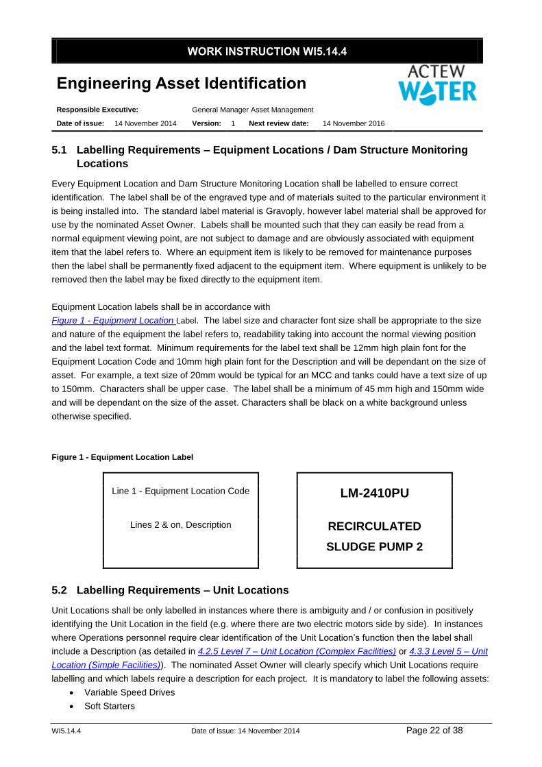
Equipment Location labels shall be in accordance with
Figure 1 - Equipment Location Label. The label size and character font size shall be appropriate to the size
and nature of the equipment the label refers to, readability taking into account the normal viewing position
and the label text format. Minimum requirements for the label text shall be 12mm high plain font for the
Equipment Location Code and 10mm high plain font for the Description and will be dependant on the size of
asset. For example, a text size of 20mm would be typical for an MCC and tanks could have a text size of up
to 150mm. Characters shall be upper case. The label shall be a minimum of 45 mm high and 150mm wide
and will be dependant on the size of the asset. Characters shall be black on a white background unless
otherwise specified.
Figure 1 - Equipment Location Label
Line 1 - Equipment Location Code LM-2410PU
Lines 2 & on, Description RECIRCULATED
SLUDGE PUMP 2
5.2 Labelling Requirements – Unit Locations
Unit Locations shall be only labelled in instances where there is ambiguity and / or confusion in positively
identifying the Unit Location in the field (e.g. where there are two electric motors side by side). In instances
where Operations personnel require clear identification of the Unit Location’s function then the label shall
include a Description (as detailed in 4.2.5 Level 7 – Unit Location (Complex Facilities) or 4.3.3 Level 5 – Unit
Location (Simple Facilities)). The nominated Asset Owner will clearly specify which Unit Locations require
labelling and which labels require a description for each project. It is mandatory to label the following assets:
Variable Speed Drives
Soft Starters
WORK INSTRUCTION WI5.14.4
Engineering Asset Identification
Responsible Executive: General Manager Asset Management
Date of issue: 14 November 2014 Version: 1 Next review date: 14 November 2016
WI5.14.4 Date of issue: 14 November 2014 Page 23 of 38
Unit Location labels shall be of the engraved type and of materials suited to the particular environment it is
being installed into. The standard label material is Gravoply. Label material shall be approved for use by the
nominated Asset Owner. Labels shall be mounted such that they can easily be read from a normal
equipment viewing point, are not subject to damage and are obviously associated with Unit Location that the
label refers to. Where an equipment item is likely to be removed for maintenance purposes then the label
shall be permanently fixed adjacent to the item. Where an equipment item is unlikely to be removed then the
label may be fixed directly to the item.
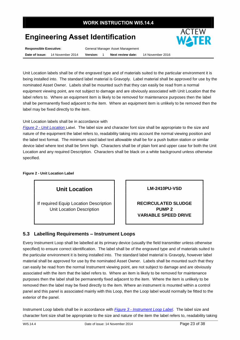
Unit Location labels shall be in accordance with
Figure 2 - Unit Location Label. The label size and character font size shall be appropriate to the size and
nature of the equipment the label refers to, readability taking into account the normal viewing position and
the label text format. The minimum sized label text allowable shall be for a push button station or similar
device label where text shall be 5mm high. Characters shall be of plain font and upper case for both the Unit
Location and any required Description. Characters shall be black on a white background unless otherwise
specified.
Figure 2 - Unit Location Label
Unit Location LM-2410PU-VSD
If required Equip Location Description
Unit Location Description RECIRCULATED SLUDGE
PUMP 2
VARIABLE SPEED DRIVE
5.3 Labelling Requirements – Instrument Loops
Every Instrument Loop shall be labelled at its primary device (usually the field transmitter unless otherwise
specified) to ensure correct identification. The label shall be of the engraved type and of materials suited to
the particular environment it is being installed into. The standard label material is Gravoply, however label
material shall be approved for use by the nominated Asset Owner. Labels shall be mounted such that they
can easily be read from the normal Instrument viewing point, are not subject to damage and are obviously
associated with the item that the label refers to. Where an item is likely to be removed for maintenance
purposes then the label shall be permanently fixed adjacent to the item. Where the item is unlikely to be
removed then the label may be fixed directly to the item. Where an instrument is mounted within a control
panel and this panel is associated mainly with this Loop, then the Loop label would normally be fitted to the
exterior of the panel.
Instrument Loop labels shall be in accordance with Figure 3 - Instrument Loop Label. The label size and
character font size shall be appropriate to the size and nature of the item the label refers to, readability taking

WORK INSTRUCTION WI5.14.4
Engineering Asset Identification
Responsible Executive: General Manager Asset Management
Date of issue: 14 November 2014 Version: 1 Next review date: 14 November 2016
WI5.14.4 Date of issue: 14 November 2014 Page 24 of 38
into account the normal viewing position and the label text format. Minimum requirements for the label text
shall be 10mm high plain font for the Instrument Loop and 6mm high plain font for the Description.
Characters to be upper case. The label shall be a minimum of 45 mm high and 100mm wide. Characters
shall be black on a white background unless otherwise specified.
Figure 3 - Instrument Loop Label
Inst. Loop LM-IL1021
Description SCRUBBER WATER RETURN FLOW
5.4 Labelling Requirements – Instrument Locations
Every Instrument Location, unless otherwise approved, shall be separately labelled with an Instrument
Location label to ensure correct identification. Typical locations where non installation of labels may be
approved are PLC I/O. Where the Instrument Loop label is affixed to, or adjacent a Loop Location device, an
Instrument Location label must also be affixed at this Location. The label shall be of the engraved type and
of materials suited to the particular environment it is being installed into. The standard label material is
Gravoply, however label material shall be approved for use by the nominated Asset Owner. Labels shall be
mounted such that they can easily be read from a normal Instrument viewing point, are not subject to
damage and are obviously associated with item that the label refers to. Where an item is likely to be
removed for maintenance purposes then the label shall be permanently fixed adjacent to the item. Where
the item is unlikely to be removed then the label may be fixed directly to the item.
Instrument Location labels shall be in accordance with Figure 4 - Instrument Location Label. The label and
character size shall be appropriate to the mounting location, amount of text and allow for ease of reading but
shall normally be 35mm wide and 20mm high with 6mm high plain font characters in upper case. Characters
shall be black on a white background unless otherwise specified.
Figure 4 - Instrument Location Label
Inst. Location or Unit Location Number LM-IL1021-FIT
5.5 Labelling Requirements – Valve Locations – Manual
Every Valve Location - Manual shall be labelled to ensure correct identification. The label shall be of the
engraved type and of materials suited to the particular environment it is being installed into. The standard

WORK INSTRUCTION WI5.14.4
Engineering Asset Identification
Responsible Executive: General Manager Asset Management
Date of issue: 14 November 2014 Version: 1 Next review date: 14 November 2016
WI5.14.4 Date of issue: 14 November 2014 Page 25 of 38
label material is Gravoply, however label material shall be approved for use by the nominated Asset Owner.
Labels shall be mounted such that they can easily be read from a normal equipment viewing point, are not
subject to damage and are obviously associated with the valve the label refers to.
Valve Location – Manual labels shall be in accordance with Figure 5 - Valve Location - Manual Label. The
label size and character font size shall be appropriate to the size and nature of the equipment the label refers
to, readability taking into account the normal viewing position and the label text format. Minimum
requirements for the label text shall be 8mm high plain font. Characters shall be black on a white background
unless otherwise specified.
Figure 5 - Valve Location - Manual Label
Valve Number 2CE19
5.6 Labelling Requirements – Piping Systems
Piping installations are to be marked in accordance with the Australian Standard AS1345.
5.7 Labelling Requirements – Units / Instruments
Every Unit and Instrument (where practicable) shall be separately labelled with an “AN” label to ensure
correct identification. The label shall be made of materials suited to the particular environment it is being
installed into. There are 3 standard types of “AN” label:
Aluminium (the default label type).
Gravoply (used in environments with high acid or alkaline concentrations).
Stainless Steel (used in aggressive environments that are generally submersible e.g. wet wells).
Aluminium labels shall be in accordance with Figure 6 - "AN" Label - Aluminium. Aluminium labels shall
normally be 19.5 x 30 x 0.3mm, black / blue print on silver MetalPRINT aluminium with an adhesive back and
11.5 point plain font characters.
Figure 6 - "AN" Label - Aluminium
WORK INSTRUCTION WI5.14.4
Engineering Asset Identification
Responsible Executive: General Manager Asset Management
Date of issue: 14 November 2014 Version: 1 Next review date: 14 November 2016
WI5.14.4 Date of issue: 14 November 2014 Page 26 of 38
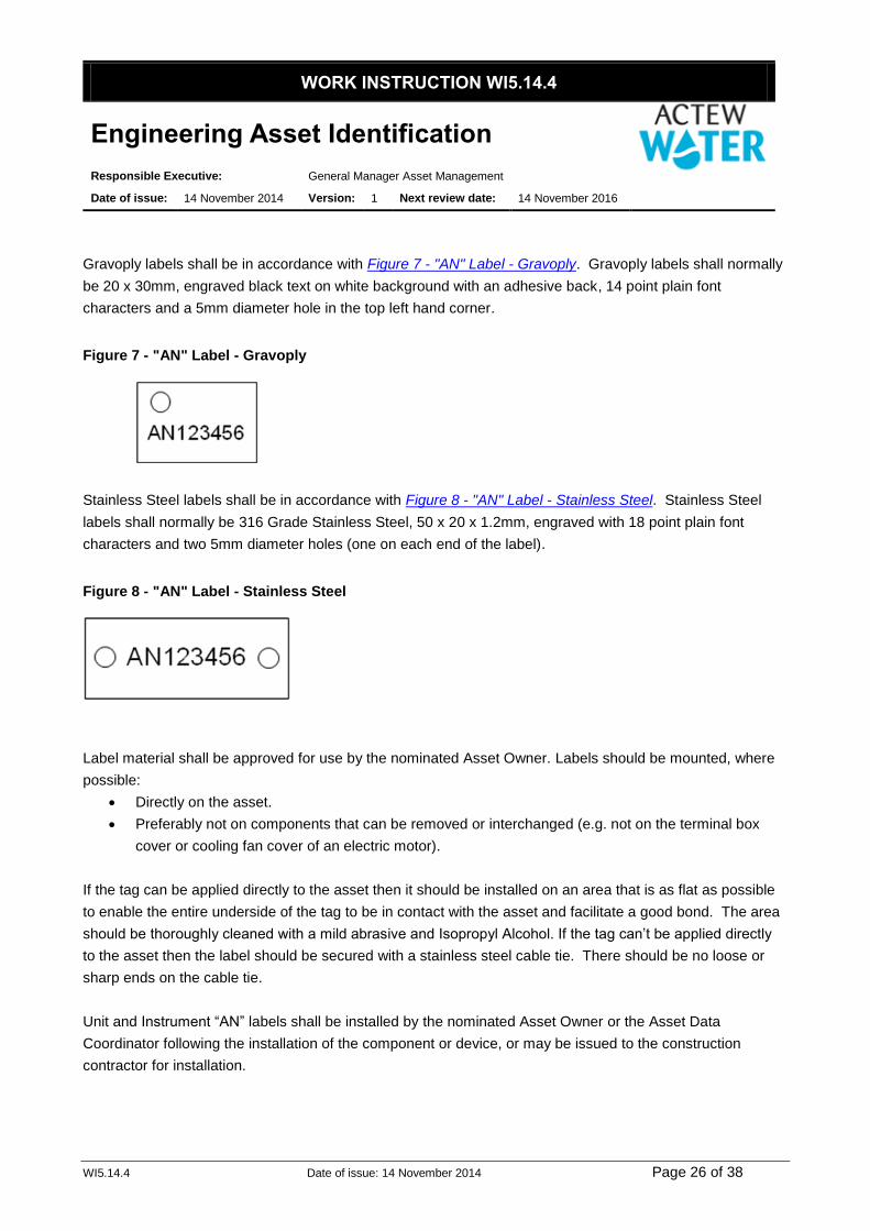
Gravoply labels shall be in accordance with Figure 7 - "AN" Label - Gravoply. Gravoply labels shall normally
be 20 x 30mm, engraved black text on white background with an adhesive back, 14 point plain font
characters and a 5mm diameter hole in the top left hand corner.
Figure 7 - "AN" Label - Gravoply
Stainless Steel labels shall be in accordance with Figure 8 - "AN" Label - Stainless Steel. Stainless Steel
labels shall normally be 316 Grade Stainless Steel, 50 x 20 x 1.2mm, engraved with 18 point plain font
characters and two 5mm diameter holes (one on each end of the label).
Figure 8 - "AN" Label - Stainless Steel
Label material shall be approved for use by the nominated Asset Owner. Labels should be mounted, where
possible:
Directly on the asset.
Preferably not on components that can be removed or interchanged (e.g. not on the terminal box
cover or cooling fan cover of an electric motor).
If the tag can be applied directly to the asset then it should be installed on an area that is as flat as possible
to enable the entire underside of the tag to be in contact with the asset and facilitate a good bond. The area
should be thoroughly cleaned with a mild abrasive and Isopropyl Alcohol. If the tag can’t be applied directly
to the asset then the label should be secured with a stainless steel cable tie. There should be no loose or
sharp ends on the cable tie.
Unit and Instrument “AN” labels shall be installed by the nominated Asset Owner or the Asset Data
Coordinator following the installation of the component or device, or may be issued to the construction
contractor for installation.

WORK INSTRUCTION WI5.14.4
Engineering Asset Identification
Responsible Executive: General Manager Asset Management
Date of issue: 14 November 2014 Version: 1 Next review date: 14 November 2016
WI5.14.4 Date of issue: 14 November 2014 Page 27 of 38
6 Related Documents
AMU 029 - EAR Data Maintenance (CAPEX / Gifted Assets)
7 References
Structure / Area Numbers at Sewer Treatment Facilities
Structure / Area Numbers at Water Treatment Facilities
Structure / Area Numbers at Bulk Water Facilities
WDS-P03 - Process & Instrumentation Drawing Symbols Legend Sheet 3 of 3 (for fluid codes)
8 Definitions
Nil
9 Tables
9.1 Facility Types and Classifications
Level 2 - Facility Type
Level 1
Functional System
Code Description Classification
Sewer Network SSF Sewage Storage Facilities Simple
STF Sewage Treatment Facilities Complex
SFF Sewer Flushing Facilities Simple
SGS Sewer Gauge Stations Simple
STS Sewer Penstocks Simple
SPS Sewage Pump Stations Simple
SVS Sewer Vent Systems Simple
SWS Sewer Weather Stations Simple
Water Network WBF Bulk Water Facilities Complex
HGF Hydro Generation Facilities Complex
WDF Water District Flow Meters Simple
WPS Water Pump Stations Simple
WRS Water Reservoirs Simple
WTF Water Treatment Facilities Complex
WVF Water Valve Farms Simple
WTV Water Transfer Valves Simple
Reclaimed Water
Network
RRS Reclaimed Water Reservoirs Simple
RTF Reclaimed Water Treatment Facilities Complex
WORK INSTRUCTION WI5.14.4
Engineering Asset Identification
Responsible Executive: General Manager Asset Management
Date of issue: 14 November 2014 Version: 1 Next review date: 14 November 2016
WI5.14.4 Date of issue: 14 November 2014 Page 28 of 38
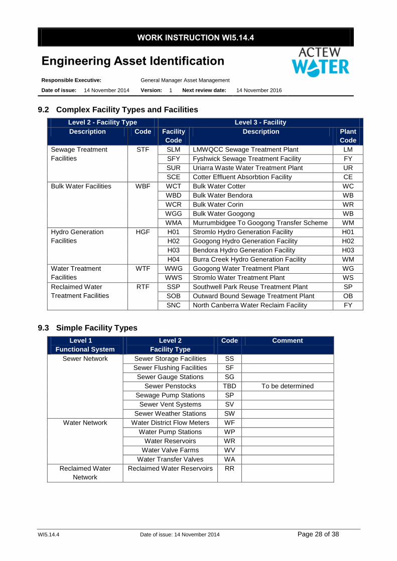
9.2 Complex Facility Types and Facilities
Level 2 - Facility Type Level 3 - Facility
Description Code Facility
Code
Description Plant
Code
Sewage Treatment
Facilities
STF SLM LMWQCC Sewage Treatment Plant LM
SFY Fyshwick Sewage Treatment Facility FY
SUR Uriarra Waste Water Treatment Plant UR
SCE Cotter Effluent Absorbtion Facility CE
Bulk Water Facilities WBF WCT Bulk Water Cotter WC
WBD Bulk Water Bendora WB
WCR Bulk Water Corin WR
WGG Bulk Water Googong WB
WMA Murrumbidgee To Googong Transfer Scheme WM
Hydro Generation
Facilities
HGF H01 Stromlo Hydro Generation Facility H01
H02 Googong Hydro Generation Facility H02
H03 Bendora Hydro Generation Facility H03
H04 Burra Creek Hydro Generation Facility WM
Water Treatment
Facilities
WTF WWG Googong Water Treatment Plant WG
WWS Stromlo Water Treatment Plant WS
Reclaimed Water
Treatment Facilities
RTF SSP Southwell Park Reuse Treatment Plant SP
SOB Outward Bound Sewage Treatment Plant OB
SNC North Canberra Water Reclaim Facility FY
9.3 Simple Facility Types
Level 1
Functional System
Level 2
Facility Type
Code Comment
Sewer Network Sewer Storage Facilities SS
Sewer Flushing Facilities SF
Sewer Gauge Stations SG
Sewer Penstocks TBD To be determined
Sewage Pump Stations SP
Sewer Vent Systems SV
Sewer Weather Stations SW
Water Network Water District Flow Meters WF
Water Pump Stations WP
Water Reservoirs WR
Water Valve Farms WV
Water Transfer Valves WA
Reclaimed Water
Network
Reclaimed Water Reservoirs RR

WORK INSTRUCTION WI5.14.4
Engineering Asset Identification
Responsible Executive: General Manager Asset Management
Date of issue: 14 November 2014 Version: 1 Next review date: 14 November 2016
WI5.14.4 Date of issue: 14 November 2014 Page 29 of 38
9.4 Equipment Type Suffix
Equipment Type Suffix
Air compressor AC
Battery and charger BC
Blower BL
Burner BU
Corporate Communications Panel CA
Centrifuge CE
Channel/Conduit CH
Chemical feeder CF
Control Panel CP
Conveyor CY
Cooling coil CC
Disintegrator DG
Dam Structure Monitoring Location DM
Earthing resistor ER
Engine generator EG
Exhaust fan EF
Filter FR
Flow element (meter) FE
Furnace FU
Heat exchanger HE
Heating coil HC
Miscellaneous equipment ME 1
Mixer MX 1
Motor Control Centre MC
Motorised valve or gate MV
PLC PC
PLC Distributed I/O Terminal Cubicle TC
Pump PU
Return fan RF
Screen/Sludge circulator SC
Sludge collector CO
Structure ST
Supply fan SF
Switchboard SB
Tank TK
Transfer fan TF
Transformer TR
Manual Valve VL
Ventilating unit VU

WORK INSTRUCTION WI5.14.4
Engineering Asset Identification
Responsible Executive: General Manager Asset Management
Date of issue: 14 November 2014 Version: 1 Next review date: 14 November 2016
WI5.14.4 Date of issue: 14 November 2014 Page 30 of 38
Note: Due to historical differences in Suffix codes used at different plants both ME and MX have in the
past been used to identify mixer equipment. The guideline for all plants is that the suffix code MX will
be used to indicate all new mixer equipment items installed after 2005.
9.5 Unit Location Suffix
Unit Location Description Suffix Sub-Type
Actuator – Motorised ACT No
Actuator – Pressurised ACT Yes
Air Conditioner - Indoor Unit ACI Yes
Air Conditioner - Outdoor Unit ACO No
Air Conditioner – Packaged ACP No
Air Dryer DRY No
Anchor ANC No
Battery Cluster BAT No
Blower BLW Yes
Blower - Integral Motor BIM Yes
Boiler BOL No
Brake - Electrical BEL No
Burner BUR No
Centrifuge CFG No
Channel CNL No
Chlorinator/Sulphonator CHL Yes
Collector/Skimmer COL Yes
Compressor - Packaged CPK Yes
Control/Indication Panel PNL No
Conveyor CON Yes
Conveyor Belt/Screw CBS Yes
Cooler CLR Yes
Coupling CPL No
Crane/Hoist CRN Yes
Crusher CRS No
Dampener - Pulsation DMP No
Davit Base DVB No
DC Power Supply DCS No
Diffuser DIF No
Disintegrator DSN Yes
Distillation System DIS No
Door/Gate Drive Assembly DGA No
Door/Gate Structure DGS Yes
Drying Bed DBD No
Ductwork DUC No
Ejector EJT No
Emergency Wash Station EMS Yes
Electrical Filter EFR Yes
Engine ENG No
Evaporator EVP No

WORK INSTRUCTION WI5.14.4
Engineering Asset Identification
Responsible Executive: General Manager Asset Management
Date of issue: 14 November 2014 Version: 1 Next review date: 14 November 2016
WI5.14.4 Date of issue: 14 November 2014 Page 31 of 38
Unit Location Description Suffix Sub-Type
Fan FAN Yes
Fan - Integral Motor FIM Yes
Feeder FDR Yes
Feeder - Integral Motor FDM Yes
Filter - Baghouse FLT Yes
Filter - Inline FLI No
Filter - Odour Scrubber FOS No
Filter Media FLM Yes
Flame Arrestor FLA No
Furnace FUR Yes
Flow Restrictor FWR No
Gauge GPR No
Gearbox GBX No
Generator GEN No
Generator - Packaged GPK No
Guide Vane GDV No
Heater HTR Yes
Hopper HOP No
Humidifier HUM Yes
Hydraulic Pack HPK Yes
Injector INJ No
Lagoon LAG No
Lift LFT No
Lightning Protection System LPS No
Load Bank LBK No
Local Control Station LCS No
Lump Breaker LMP No
Mixer MIX Yes
Mixer - Integral Motor MIM Yes
Mixer - Static MXS No
Motor MTR No
Motor Control Centre MCC No
Motor Exciter MTX No
Motor Starter Cell MSC No
Nozzle Assembly NZL No
Pipework PWK No
PLC PLC No
Power Outlet PWO Yes
Pump PMP Yes
Pump - Integral Motor PIM Yes
Pole/Mast PLE No
Pump Shaft Assembly PSA No
Pressure Vessel PSV No
Radio RAD No
Refrigerator RFG No

WORK INSTRUCTION WI5.14.4
Engineering Asset Identification
Responsible Executive: General Manager Asset Management
Date of issue: 14 November 2014 Version: 1 Next review date: 14 November 2016
WI5.14.4 Date of issue: 14 November 2014 Page 32 of 38
Unit Location Description Suffix Sub-Type
Sampler SAM No
Scale SCA No
Screen SCN Yes
Scrubber SCB Yes
Separator SPR Yes
Silencer SLN No
Slipring Assembly SLP No
Soft Starter SFS No
Solar Panel SLR No
Solenoid SOL No
Spray Assembly SPA No
Structure STR No
Sump SMP No
Switchboard SWB Yes
Tank TNK No
Torque Limiter TOR Yes
Torque Controller - Mechanical TCM No
Transformer TXF Yes
Turbine TUR No
Uninterruptible Power Supply UPS No
UV Lamp UVE No
Valve VLV Yes
Vaporiser VAP No
Variable Speed Drive VSD No
Vibrator VIB Yes
Workshop Equipment WSP Yes
9.6 Unit Sub-types
Unit Type Sub-type Comments
Actuator (pressurised) Hydraulic
Pneumatic
Air Conditioner (Indoor Unit) Wall Mounted
Ceiling Cassette
Ceiling Suspended
Ducted
Blower Centrifugal Single Stage
Centrifugal Multi Stage
Packaged
Ring
Roots
Screw

WORK INSTRUCTION WI5.14.4
Engineering Asset Identification
Responsible Executive: General Manager Asset Management
Date of issue: 14 November 2014 Version: 1 Next review date: 14 November 2016
WI5.14.4 Date of issue: 14 November 2014 Page 33 of 38
Unit Type Sub-type Comments
Blower (integral motor) Same as for Blower
Chlorinator/Sulphonator Chlorinator
Sulphonator
Collector/Skimmer Collector - Flight
Collector - Rotary
Collector - Screw
Skimmer - Helical
Compressor (packaged) Centrifugal
Lobe
Piston
Screw
Conveyor Screw
Belt
Conveyor Belt/Screw Same as for Conveyor
Cooler Rotary Disc
Counter-Flow
Spray
Evaporative
Crane/Hoist Davit Arm/Jib - Fixed
Gantry
Lifting Beam
Lifting Beam + Hoist Lifting beam always
includes trolley - hoists
are classified as minor
non-system assets
Disintegrator Pumped
Inline
Door/Gate Structure Boom Gate
Hinged Gate
Roller Door
Sliding Gate
Electrical Filter Harmonic - Active
Harmonic - Passive
Sine
RFI
EMC
Emergency Shower & Eye Wash
Station Eye Wash Station
Shower
Shower & Eye Wash Station
Fan Centrifugal
Axial
Fan (integral motor) Same as for Fan
Feeder Screw
Belt
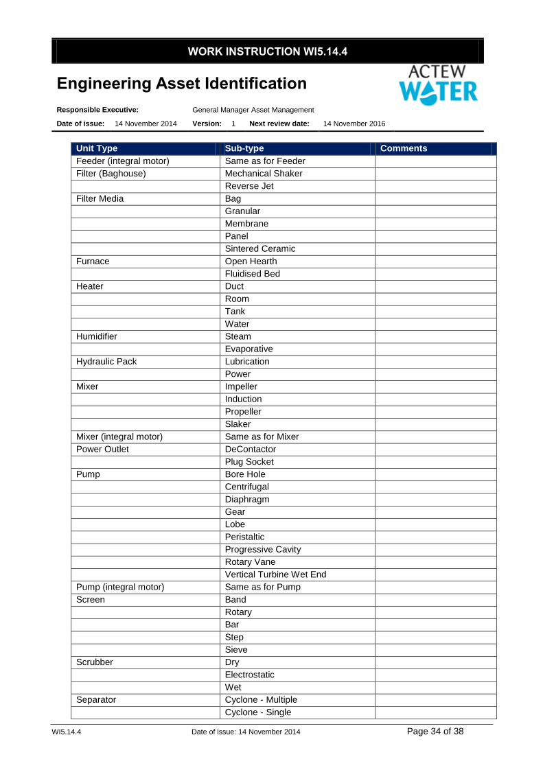
WORK INSTRUCTION WI5.14.4
Engineering Asset Identification
Responsible Executive: General Manager Asset Management
Date of issue: 14 November 2014 Version: 1 Next review date: 14 November 2016
WI5.14.4 Date of issue: 14 November 2014 Page 34 of 38
Unit Type Sub-type Comments
Feeder (integral motor) Same as for Feeder
Filter (Baghouse) Mechanical Shaker
Reverse Jet
Filter Media Bag
Granular
Membrane
Panel
Sintered Ceramic
Furnace Open Hearth
Fluidised Bed
Heater Duct
Room
Tank
Water
Humidifier Steam
Evaporative
Hydraulic Pack Lubrication
Power
Mixer Impeller
Induction
Propeller
Slaker
Mixer (integral motor) Same as for Mixer
Power Outlet DeContactor
Plug Socket
Pump Bore Hole
Centrifugal
Diaphragm
Gear
Lobe
Peristaltic
Progressive Cavity
Rotary Vane
Vertical Turbine Wet End
Pump (integral motor) Same as for Pump
Screen Band
Rotary
Bar
Step
Sieve
Scrubber Dry
Electrostatic
Wet
Separator Cyclone - Multiple
Cyclone - Single

WORK INSTRUCTION WI5.14.4
Engineering Asset Identification
Responsible Executive: General Manager Asset Management
Date of issue: 14 November 2014 Version: 1 Next review date: 14 November 2016
WI5.14.4 Date of issue: 14 November 2014 Page 35 of 38
Unit Type Sub-type Comments
Switchboard High Voltage Metal Clad
Low Voltage Metal Clad
Distribution Board
Torque Limiter Clutch
Shear Pin
Transformer Power
Autotransformer
Valve Air Damper
Ball
Butterfly
Check
Diaphragm
Eductor
Flap
Gate
Globe
Knife Gate
Overfill Prevention
Penstock
Pinch
Piston
Plug
Pressure Reduction/Regulation
Pressure Relief
Rotary
Workshop Equipment Band Saw
Bead Blaster
Bending Machine
Drilling Machine
Grinder
Guillotine
Hydraulic Press
Lathe
Milling Machine
Power Hacksaw
Threading Machine

WORK INSTRUCTION WI5.14.4
Engineering Asset Identification
Responsible Executive: General Manager Asset Management
Date of issue: 14 November 2014 Version: 1 Next review date: 14 November 2016
WI5.14.4 Date of issue: 14 November 2014 Page 36 of 38
9.7 Instrument Location Suffix
Code First letter Modifier Succeeding
Letters
Measured or
Initiating
Passive
function
Output
function
Modifiers
A Analysis Alarm
B Flame
C Control
D Density Differential
E Voltage (EMF) Element
F Flow Rate Ratio
G Gauge or Dimension
H Hand (Manual
Initiation)
High
I Current Indicate
J Power
K Time
L Level Low
M Moisture/Humidity Middle
(Intermediate)
N
O Torque
P Pressure / Vacuum
Q Quantity / Event Integrate /
Totalise
R Radiation Record /
S Speed / Frequency Safety Switch
T Temperature Transmit
U Multi-variable Multi-
function
Multi-function Multi-function
V Valve /
Damper
W Weight / Force
X Unclassified Variables
Y Vibration Compute
Z Position Actuate

WORK INSTRUCTION WI5.14.4
Engineering Asset Identification
Responsible Executive: General Manager Asset Management
Date of issue: 14 November 2014 Version: 1 Next review date: 14 November 2016
WI5.14.4 Date of issue: 14 November 2014 Page 37 of 38
9.8 Instrument Variable
Instrument Variable
Acceleration
Ammonia
Back Drive
Burner
Chlorine
Combo
Conductivity
Current
Dissolved Oxygen
Flow
Fluoride
Gas
Input
Level
Lightning
Moisture
NA
Nitrate
ORP
Output
Oxygen
Particle Counter
pH
Phosphorus
Position
Power
Pressure
Speed
Streaming Current
Sulphur Dioxide
Suspended Solids
Temperature
Turbidity
UV
Valve
Voltage
Weight

WORK INSTRUCTION WI5.14.4
Engineering Asset Identification
Responsible Executive: General Manager Asset Management
Date of issue: 14 November 2014 Version: 1 Next review date: 14 November 2016
WI5.14.4 Date of issue: 14 November 2014 Page 38 of 38
9.9 Instrument Type
Instrument Type
Controller
Element
Indicator
PLC Card
Positioner
Power Supply
Switch
Transmitter
9.10 Instrument Sub-type
Instrument Sub-type
Float
Hydrostatic
Load Cell
Magnetic
Microwave
NA
Pneumatic
Probe
Proximity
Rotating Mass
Ultrasonic
Ultrasonic via Level


![[ 1b ] Approaches to the identification of asset market bubbles](https://static.fdocuments.us/doc/165x107/5681499e550346895db6e0c3/-1b-approaches-to-the-identification-of-asset-market-bubbles.jpg)


