Engineering and Economic Implications of Ice Classed ...robdvorak.com/MIT Thesis.pdf · This thesis...
93
Engineering and Economic Implications of Ice‐Classed Containerships by Robert E. Dvorak B.S. Naval Architecture and Marine Engineering Webb Institute, 2007 Submitted to the Department of Civil and Environmental Engineering and the Department of Mechanical Engineering in Partial Fulfillment of the Requirements for the Degrees of Master of Science in Transportation and Master of Science in Naval Architecture and Marine Engineering at the Massachusetts Institute of Technology June 2009 © 2009 Robert E. Dvorak All rights reserved The author hereby grants to MIT permission to reproduce and to distribute publicly paper and electronic copies of this thesis document in whole or in part in any medium now known or hereafter created. Signature of Author Department of Civil and Environmental Engineering Department of Mechanical Engineering May 8, 2009 Certified by Henry S. Marcus Professor of Marine Systems Thesis Supervisor Certified by Trent R. Gooding Associate Professor of the Practice of Naval Construction and Engineering Thesis Reader Accepted by David E. Hardt Chairman, Departmental Committee for Graduate Students Accepted by Daniele Veneziano Chairman, Departmental Committee for Graduate Students
Transcript of Engineering and Economic Implications of Ice Classed ...robdvorak.com/MIT Thesis.pdf · This thesis...
Engineering and Economic Implications of Ice‐Classed Containerships
by Robert E. Dvorak
B.S. Naval Architecture and Marine Engineering
Webb Institute, 2007
Submitted to the Department of Civil and Environmental Engineering and the Department of Mechanical Engineering
in Partial Fulfillment of the Requirements for the Degrees of
Master of Science in Transportation
and
Master of Science in Naval Architecture and Marine Engineering
at the Massachusetts Institute of Technology
June 2009
© 2009 Robert E. Dvorak All rights reserved
The author hereby grants to MIT permission to reproduce and to
distribute publicly paper and electronic copies of this thesis document in whole or in part in any medium now known or hereafter created.
Signature of Author
Department of Civil and Environmental Engineering Department of Mechanical Engineering
May 8, 2009
Certified by Henry S. Marcus
Professor of Marine Systems Thesis Supervisor
Certified by Trent R. Gooding
Associate Professor of the Practice of Naval Construction and Engineering Thesis Reader
Accepted by David E. Hardt
Chairman, Departmental Committee for Graduate Students
Accepted by Daniele Veneziano
Chairman, Departmental Committee for Graduate Students


Engineering and Economic Implications of Ice‐Classed Containerships
by Robert E. Dvorak
Submitted to the Department of Civil and Environmental Engineering and the
Department of Mechanical Engineering on May 8, 2009 in Partial Fulfillment of the Requirements for the Degrees of Master of Science in Transportation and
Master of Science in Naval Architecture and Marine Engineering
Abstract
The Arctic is becoming increasingly attractive for shipping. With the potential savings in transit time and the untapped natural resources, both the shipping and offshore industries are pouring capital into research and development.
Myriad different ice‐classes are described. Every classification society and country has their own system of ice‐classing vessels, which leads to complexities within the system. The Polar Rules are looking to harmonize all of the different methods into one set of standards, thus simplifying the process.
Also addressed will be the effect of ice‐class on vessel design. The hull shape and structure, propulsion machinery, and auxiliary systems are all affected by ice‐classing a vessel.
Herein, the reader will find a presentation of the percentage increases in weight, power, fuel consumption, and cost of several different ice‐classes over conventional containerships. To increase the ice‐class slightly, the data is within margins of error and thus, there are no increases (especially with high speed LNG and container vessels). However, to increase the ice‐class to the highest class analyzed, the weight, power, fuel consumption, and cost increase substantially.
Ice‐classed containerships may become economical in the future when the ice cover diminishes due to global warming. Presently, routing containerships over the Arctic is generally not considered by the industry to be economically, politically, or environmentally feasible for continuous, reliable service. This thesis provides insight into the engineering and economic implications of ice‐classed containerships.
Thesis Supervisor: Henry S. Marcus
Title: Professor of Marine Systems
Thesis Reader: Trent R. Gooding
Title: Associate Professor of the Practice of Naval Construction and Engineering

Acknowledgements
The author would like to thank Professor Henry S. Marcus for his support and guidance
throughout this project. Additionally, Lawson Brigham was a valuable source of practical knowledge of
icebreaking and Russell Pollock provided helpful data from his thesis, “Economic Feasibility of Shipping
Containers Through the Arctic.”
He would also like to thank the numerous industry contacts for providing data for use in this
project: Keith Michel (Herbert Engineering Corp), Robert Hindley (Lloyd’s Register), Nikolaos Kakalis
(DNV), Dave Amand (EPA), Richard Hayward and Andrew Robertson (Germanischer Lloyd), Peter Tang‐
Jensen and Ge Wang (ABS), and others in the containership and LNG industries that were so helpful.
He wants to thank his thesis reader Professor Trent Gooding for his immense help in the home
stretch.


7
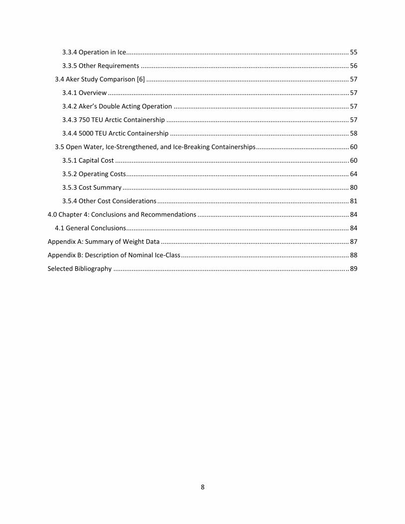
Table of Contents
Abstract ......................................................................................................................................................... 3
Acknowledgements ....................................................................................................................................... 5
Table of Contents .......................................................................................................................................... 7
List of Figures ................................................................................................................................................ 9
List of Tables ............................................................................................................................................... 11
Definitions and Nomenclature .................................................................................................................... 13
1.0 Chapter 1: Introduction and Purpose ................................................................................................... 15
1.1 Overview and Background ................................................................................................................ 15
1.2 Purpose ............................................................................................................................................. 19
1.3 Recent Developments ....................................................................................................................... 19
2.0 Chapter 2: Class ..................................................................................................................................... 20
2.1 Introduction ...................................................................................................................................... 20
2.2 Finnish‐Swedish Ice‐Class Rules ........................................................................................................ 22
2.3 Russian Maritime Register of Shipping (RMRS) Ice‐Class Rules ........................................................ 24
2.4 Canadian Arctic Shipping Pollution Prevention Rules (CASPPR) ....................................................... 26
2.5 DNV Class Rules ................................................................................................................................. 29
2.6 ABS Class Rules .................................................................................................................................. 30
2.7 Polar Class Rules ................................................................................................................................ 33
2.7.1 Polar Class Description and Application ............................................................................. 33
2.7.2 Structural Requirements for Polar Class Ships .................................................................... 33
2.7.3 Machinery Requirements for Polar Class Ships .................................................................. 34
2.8 Equivalencies ..................................................................................................................................... 34
3.0 Chapter 3: Arctic Containerships .......................................................................................................... 41
3.1 Introduction ...................................................................................................................................... 41
3.2 Fleet Survey ....................................................................................................................................... 41
3.3 Impact of Ice‐Class on Vessel Design ................................................................................................ 44
3.3.1 Hull Form .................................................................................................................................... 44
3.3.2 Propulsion .................................................................................................................................. 52
3.3.3 Auxiliary Systems ....................................................................................................................... 55
8
3.3.4 Operation in Ice .......................................................................................................................... 55
3.3.5 Other Requirements .................................................................................................................. 56
3.4 Aker Study Comparison [6] ............................................................................................................... 57
3.4.1 Overview .................................................................................................................................... 57
3.4.2 Aker’s Double Acting Operation ................................................................................................ 57
3.4.3 750 TEU Arctic Containership .................................................................................................... 57
3.4.4 5000 TEU Arctic Containership .................................................................................................. 58
3.5 Open Water, Ice‐Strengthened, and Ice‐Breaking Containerships ................................................... 60
3.5.1 Capital Cost ................................................................................................................................ 60
3.5.2 Operating Costs .......................................................................................................................... 64
3.5.3 Cost Summary ............................................................................................................................ 80
3.5.4 Other Cost Considerations ......................................................................................................... 81
4.0 Chapter 4: Conclusions and Recommendations ................................................................................... 84
4.1 General Conclusions .......................................................................................................................... 84
Appendix A: Summary of Weight Data ....................................................................................................... 87
Appendix B: Description of Nominal Ice‐Class ............................................................................................ 88
Selected Bibliography ................................................................................................................................. 89
9
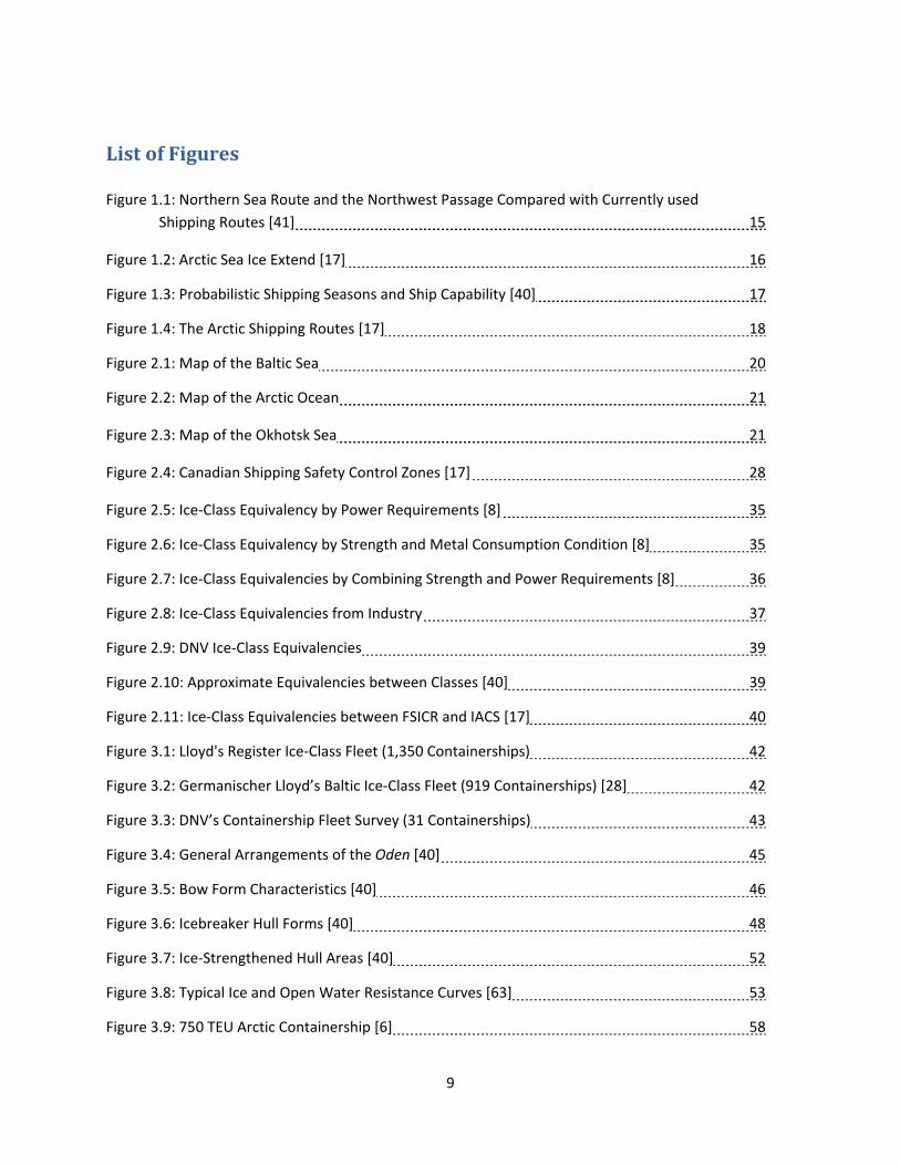
List of Figures
Figure 1.1: Northern Sea Route and the Northwest Passage Compared with Currently used
Shipping Routes [41] 15
Figure 1.2: Arctic Sea Ice Extend [17] 16
Figure 1.3: Probabilistic Shipping Seasons and Ship Capability [40] 17
Figure 1.4: The Arctic Shipping Routes [17] 18
Figure 2.1: Map of the Baltic Sea 20
Figure 2.2: Map of the Arctic Ocean 21
Figure 2.3: Map of the Okhotsk Sea 21
Figure 2.4: Canadian Shipping Safety Control Zones [17] 28
Figure 2.5: Ice‐Class Equivalency by Power Requirements [8] 35
Figure 2.6: Ice‐Class Equivalency by Strength and Metal Consumption Condition [8] 35
Figure 2.7: Ice‐Class Equivalencies by Combining Strength and Power Requirements [8] 36
Figure 2.8: Ice‐Class Equivalencies from Industry 37
Figure 2.9: DNV Ice‐Class Equivalencies 39
Figure 2.10: Approximate Equivalencies between Classes [40] 39
Figure 2.11: Ice‐Class Equivalencies between FSICR and IACS [17] 40
Figure 3.1: Lloyd's Register Ice‐Class Fleet (1,350 Containerships) 42
Figure 3.2: Germanischer Lloyd’s Baltic Ice‐Class Fleet (919 Containerships) [28] 42
Figure 3.3: DNV’s Containership Fleet Survey (31 Containerships) 43
Figure 3.4: General Arrangements of the Oden [40] 45
Figure 3.5: Bow Form Characteristics [40] 46
Figure 3.6: Icebreaker Hull Forms [40] 48
Figure 3.7: Ice‐Strengthened Hull Areas [40] 52
Figure 3.8: Typical Ice and Open Water Resistance Curves [63] 53
Figure 3.9: 750 TEU Arctic Containership [6] 58
10
Figure 3.10: 5000 TEU Arctic Containership [6] 58
Figure 3.11: Increase in Hull Steel due to Ice‐Class 61
Figure 3.12: Increase in Lightship due to Ice‐Class 62
Figure 3.13: Building Prices for Containerships [59] 63
Figure 3.14: Comparison of Open Water and Ice‐Classed Containership Prices [59] 64
Figure 3.15: Experimental Dependence of Residual Resistance Coefficient on Froude Number [52] 68 Figure 3.16: TPI for Different Size Containerships [22] 69
Figure 3.17: TPI for Different Size Containerships [22] 70
Figure 3.18: Power Required to Maintain Speed in Open Water 74
Figure 3.19: Difference in Speed with Increased Weight 75
Figure 3.20: The Installed Power and Required Power for Differing Ice‐Classes 76
Figure 3.21: Specific Fuel Consumption Over Time [30] 77
Figure 3.22: Ship Cost Breakdown 80

11
List of Tables
Table 2.1: Finnish‐Swedish Ice‐Class Rules [20, 32] 23
Table 2.2: RMRS Ice Strengthening Notations [20] 25
Table 2.3: DNV Ice‐Class Notations and Descriptions 29
Table 2.4: Steps in Ice Strengthening of Side Structures [2] 31
Table 2.5: Performance Requirements [2] 32
Table 2.6: Polar Class Descriptions [54] 33
Table 2.7: Approximate Equivalence of Class Symbols for Ice Strengthening Between
Classification Societies [20] 38
Table 3.1: Effect of Bow Shape on Power [48] 50
Table 3.2: Principal Characteristics [6] 59
Table 3.3: Cost of Different Ice‐Classed Containerships [50] 63
Table 3.4: General Characteristics of Ship 65
Table 3.5: Given and Assumed Values for Fuel Calculations 66
Table 3.6: Principal Characteristics of the Containership in the Graph Below [52] 67
Table 3.7: Comparison of ASSET Ships with the Containerships 71
Table 3.8: Effect of Changing Displacement on Residual Resistance 72
Table 3.9: Change in Draft with Differing Ice‐Classes 73
Table 3.10: Change in Power with Differing Ice‐Classes 73
Table 3.11: Specific Fuel Oil Consumption for Various Man B&W Medium Speed
Marine Diesel Engines [21] 78
Table 3.12: Change in Specific Fuel Consumption with Differing Ice‐Classes using
Required Power 79
Table 3.13: Change in Specific Fuel Consumption with Differing Ice‐Classes using
Installed Power 79
Table 3.14: Overall Summary of Ice‐Class Differences 81
Table 4.1: Summary of Ice‐Classes Effect on Weight, Power, Fuel Consumption, and Cost 85

12
Table A.1: Summary of Weight, Power, and Cost Data 87
Table B.1: Nominal Ice‐Classes 88

13
Definitions and Nomenclature
1. ABS – American Bureau of Shipping
2. AIRSS – Arctic Ice Regime Shipping System
3. ASSET – Advanced Surface Ship Evaluation Tool
4. Brash Ice – A fairway channel which has been cut by an icebreaker and continuously
broken and re‐frozen with the passage of shipping
5. CASPPR – Canadian Arctic Shipping Pollution Prevention Rules
6. CPP – Controllable Pitch Propeller
7. DAPPB – Double Acting Pusher Puller Barge system
8. DAS – Double Acting Ship concept or Double Acting Stern
9. DAT – Double Acting Tanker
10. DEICE – DNV Notation for additional ice protection
11. DNV – Det Norske Veritas
12. FE – Finite Element
13. FEM – Finite Element Modeling
14. FEU – Forty‐Foot Equivalent Unit
15. FMA – Finnish Maritime Administration
16. FPP – Fixed Pitch Propeller
17. Fr – Froude Number
18. FS – Finnish‐Swedish
19. FSICR – Finnish‐Swedish Ice‐Class Rules
20. FY Ice – First year ice up to 120 cm thick and low ice‐strength properties
21. g – Universal Gravitational Constant (9.81 m/s)
22. IACS – International Association of Classification Societies
23. IM – Ice Multiplier
24. IN – Ice Numeral
25. ITTC – International Towing Tank Conference
26. JIY = LU – Russian Maritime Register Rules Notation
27. MDO – Marine Diesel Oil
28. MGO – Marine Gas Oil
29. MT – Metric Ton
30. MY Ice – Multi‐year ice up to 3 m or more with high ice‐strength properties (Caused by
progressive leeching out of salts and minerals trapped when the ice is
first formed. With the leakage of these impurities, the ice becomes
much stronger).
31. NCR – Normal Continuous Rating
32. NORDREG – Arctic marine traffic system
33. NSR – Northern Sea Route
34. NWP – Northwest Passage
35. PC# – Polar Class # (ex. PC1 – Polar Class 1)
14
36. PE – Effective Power
37. ρSW – Density of Salt Water at 70⁰F
38. ReN – Reynold’s Number
39. RMRS – Russian Maritime Register of Shipping
40. RR – Residuary Resistance
41. RT – Total Resistance
42. SFC – Specific Fuel Consumption
43. SMA – Swedish Maritime Administration
44. TEU – Twenty‐Foot Equivalent Unit
45. VS – Ship Speed
46. WMO – World Maritime Organization
47. WSA – Wetted Surface Area
48. ZDS – Zone‐Date System

15
1.0 Chapter 1: Introduction and Purpose
1.1 Overview and Background
With both intense climatic change and increased natural resource development, the Arctic is
becoming a new area of development for the global economy. Climate change has powerful effects on
the Arctic, where the average temperature has risen at twice the rate of the rest of the planet [13]. In
combination with estimates of 25 percent of the unexploited gas and oil reserves and up to 60 percent
savings in transit distance (See Figure 1.1), the Arctic is emerging as a prominent area of investigation
and research. Currently, most of the development is in the natural resource sector.
Figure 1.1: Northern Sea Route and the Northwest Passage Compared with currently used Shipping Routes [41]
One major requirement of a containership service is the stability of its schedule. It mandates a
reliable, weekly service. The Arctic offers up to a 60 percent reduction in distance, thus ideally
decreasing transit time. However, the Arctic has unpredictable ice conditions which can cause delays.
Additionally, ice‐classed containerships come with an increased capital and operating cost, plus
transiting at slower speeds. Ice‐classing a containership may cause a decrease in cargo space due to
16
increased structure and closer frame spacing. The double acting concept, which will be explained in
greater detail later in this thesis (Section 3.4.2), is patented. The capital cost is increased when this
method is used.
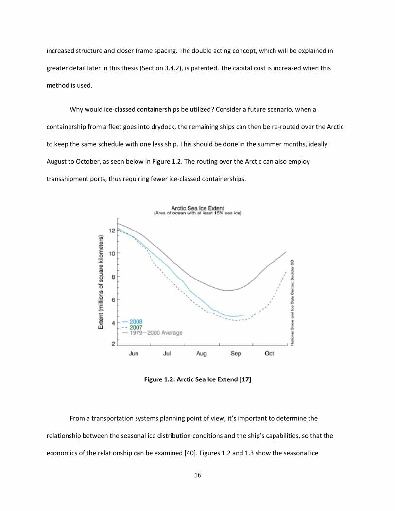
Why would ice‐classed containerships be utilized? Consider a future scenario, when a
containership from a fleet goes into drydock, the remaining ships can then be re‐routed over the Arctic
to keep the same schedule with one less ship. This should be done in the summer months, ideally
August to October, as seen below in Figure 1.2. The routing over the Arctic can also employ
transshipment ports, thus requiring fewer ice‐classed containerships.
Figure 1.2: Arctic Sea Ice Extend [17]
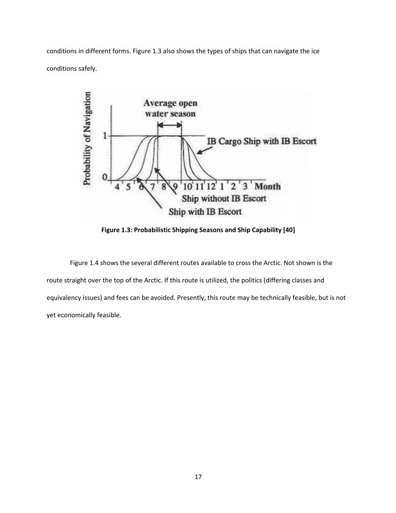
From a transportation systems planning point of view, it’s important to determine the
relationship between the seasonal ice distribution conditions and the ship’s capabilities, so that the
economics of the relationship can be examined [40]. Figures 1.2 and 1.3 show the seasonal ice
17
conditions in different forms. Figure 1.3 also shows the types of ships that can navigate the ice
conditions safely.
Figure 1.3: Probabilistic Shipping Seasons and Ship Capability [40]
Figure 1.4 shows the several different routes available to cross the Arctic. Not shown is the
route straight over the top of the Arctic. If this route is utilized, the politics (differing classes and
equivalency issues) and fees can be avoided. Presently, this route may be technically feasible, but is not
yet economically feasible.

18
Figure 1.4: The Arctic Shipping Routes [17]
Environmental issues will have to be examined. These are not in the scope of this thesis, thus
will be mentioned only briefly. Arctic areas are very sensitive to discharge of oil and other pollutants.
The low temperature will preserve the pollutants, and due to the sensitive ecological balance there
should be ‘zero tolerance’ with regard to discharge. Due to the remote location of many of the new oil
fields, shore‐based contingency plans and resources are limited and represent a challenge for the
industry and national authorities [43]. Thus, the Arctic Ocean is a no discharge ocean. This causes
several problems with ballast water management. Also, the air emissions and noise from the ships can
interrupt the serene environment. However, some proponents argue that the emissions saved by
cutting 2,500 miles to 3,750 miles off traditional routes will contribute to reversing the warming that is
melting the polar ice in the first place [9].
19
1.2 Purpose
The purpose of this thesis is to determine the feasibility of ice‐classed containerships. Several
different sized containerships with several different ice‐classes were analyzed with regards to weight,
power, fuel consumption, and cost. The results of this analysis and the viability of ice‐classed
containerships in the future are presented.
1.3 Recent Developments
Germany’s Beluga Shipping plans to deploy a ship through the Northern Sea Route this summer.
As stated above, this route cuts thousands of miles off of the normal sailing route via the Suez Canal.
From Bremen to Shanghai, 3,200 nautical miles can be saved. Beluga would have used the NSR last
summer if the necessary permits had been obtained from the Russian authorities. The ships will operate
independently of icebreaker assistance since the economic benefits would be lost. The route is only
available six to ten weeks and must be at least 90% ice‐free because of the dangers posed by drifts.
Beluga will be the first Western Europe shipping company to attempt the passage without assistance.
Aker Arctic Technology is carrying out an NSR feasibility study determining what type of ship should be
used and the viability of the passage. The main obstacle to using the NSR remains psychological. If you
are stuck in ice in Russian waters, what is the reliability and cost of the Russian icebreaker service? It is
almost two decades old; the service is the same that has been around since the early 1990s when the
route was first opened [27].

20
2.0 Chapter 2: Class
2.1 Introduction
Currently, there are many different ice‐classes in use. The countries bordering the Arctic include
Russia, Canada, Finland, Sweden, and the USA, and their classification societies each have a different set
of ice‐classes. The requirements span the spectrum from hull strengthening to power requirements. The
purpose of ice‐classes is to permit the safe operation of ships in ice‐covered sea areas [42]. There are
three main regions where ice‐classes are applicable; the Baltic Sea, the Arctic Ocean, and the Okhotsk
Sea (see Figures 2.1‐2.3). Also, inland lakes such as the Great Lakes have supplemental regulations
regarding operation during winter months.
Figure 2.1: Map of the Baltic Sea

21
Figure 2.2: Map of the Arctic Ocean
Figure 2.3: Map of the Okhotsk Sea

22
The ice‐classes endeavor to ensure the safety of the hull and essential propulsion machinery.
Additionally, sufficient power for safe operations in ice covered waters must be demonstrated. The hull
structure, propeller, and propeller shaft need to be strengthened to withstand loading with ice
interactions.
Classification ice rules are based on the ice thickness the ship is intended to navigate in. The
thicker the ice, the greater the hull reinforcement strength, propeller thickness, and steering gear
strengthening the ship will need to navigate safely. The regulations also take into account independent
or escorted operations [20].
2.2 FinnishSwedish IceClass Rules
The Finnish Maritime Administration (FMA) and the Swedish Maritime Administration (SMA)
created the Finnish‐Swedish Ice‐Class Rules (FSICR) with consultation from various classification societies
[20]. A description of each Finnish Swedish Ice‐Class is shown in Table 2.1 below.
The Finnish‐Swedish Ice‐Class Rules apply only to first‐year ice conditions in the Northern Baltic.
The Baltic has a relatively low salt content, so the ice that is formed is stronger.

23
Table 2.1: Finnish‐Swedish Ice‐Class Rules [20, 32]
Ice
Class Ice Description
For Navigation
in
IA
Super
First year ice thickness 1.0m.
Special ice class IA Super, ships whose structural strength in essential
areas affecting their ability to navigate in ice essentially exceeds the
requirements of ice class IA and which as regards hull form and engine
output are capable of navigation under difficult ice conditions without
the assistance of ice breakers. Engine output will not be less than
2800kW.
Escorted operation in all Baltic ice conditions.
Extremely
difficult ice
conditions
IA First year ice thickness 0.8m.
Ships with such structure, engine output and other properties that they
are capable of navigating in difficult ice conditions, with the assistance
of icebreakers when necessary. Escorted operation medium (smaller
vessels) and severe Baltic ice conditions. Engine output will not be less
than 1000kW.
Difficult ice
conditions
IB First year ice thickness 0.6m.
Ships with such structure, engine output and other properties that they
are capable of navigating in moderate ice conditions. Escorted
operation in medium ice conditions.
Moderately
difficult ice
conditions
IC First year ice thickness 0.4m.
Ships with such structure, engine output and other properties that they
are capable of navigating in light ice conditions. Escorted operation in
light ice conditions.
Easy ice
conditions
II Ships that have a steel hull and that are structurally fit for navigation in
the open sea and that, despite not being strengthened for navigation in
ice, are capable of navigating in very light ice conditions with their own
propulsion machinery.
Very easy ice
conditions
III Ships that do not belong to ice classes mentioned above.
24
The ice‐class and tonnage requirements may vary depending on the severity of the winter
season. The two administrations (Finland and Sweden) provide icebreaker assistance, when needed, to
ships during the winter. Additionally, they provide navigational limitations on a weekly basis depending
on ice conditions. The FSICR criteria are driven by the maintenance of ship speed in ice, ensuring the
continuity of trade in the winter. Thus in more severe winters, smaller ports without their own
icebreakers may be closed temporarily. These traffic restrictions can also be accompanied with loading
restrictions (ie. 1000 MT of loaded/unloaded goods per port). Also, if a vessel is damaged, its ice‐class
notation can be withdrawn and it may be issued a new, lower ice‐class notation [20, 32].
The various ice‐classes have different meanings depending on one’s perspective. For example,
an ice class of Finnish‐Swedish 1A may represent several connotations. Technically, the hull steel
structure and rudder are designed for pressures from 0.8 m thick first‐year ice. Also, the propeller and
shafting are designed for impact loads from ice pieces. The power requirement is given by a minimum
maintainable ahead speed of 5 knots in 1.0 m thick brash ice. Commercially, this vessel is then suitable
for assisted navigation in first‐year ice in the northern Baltic.
2.3 Russian Maritime Register of Shipping (RMRS) IceClass Rules
The Russian Maritime Register Rules apply to both first‐ and multi‐year ice. The Russians also
have stability (intact and damaged) requirements in their ice‐class rules. The Russian’s set of rules are
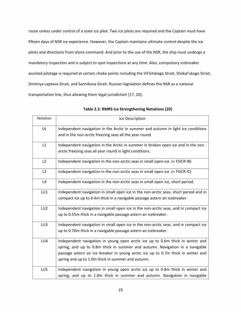
the only set that aren’t based on the FSICR guidelines. Table 2.2 provides the descriptions of the Russian
Maritime Register of Shipping Ice‐Class Rules.
The Russian’s have several guidelines that must be followed to navigate the NSR. The Captain of
a ship sailing through the Northern Sea Route is required to submit a notification and request of passage
to the Russian Administration (lead time of four months) and also guarantee payment of the icebreaking
dues. While transiting the NSR, the ship must report twice a day and must maintain the pre‐determined
25
route unless under control of a state ice pilot. Two ice pilots are required and the Captain must have
fifteen days of NSR ice experience. However, the Captain maintains ultimate control despite the ice
pilots and directions from shore command. And prior to the use of the NSR, the ship must undergo a
mandatory inspection and is subject to spot inspections at any time. Also, compulsory icebreaker
assisted pilotage is required at certain choke points including the Vil’kitskogo Strait, Shokal’skogo Strait,
Dmitriya Lapteva Strait, and Sannikova Strait. Russian legislation defines the NSR as a national
transportation line, thus allowing them legal jurisdiction [17, 20].
Table 2.2: RMRS Ice Strengthening Notations [20]
Notation Ice Description
UL Independent navigation in the Arctic in summer and autumn in light ice conditions
and in the non‐arctic freezing seas all the year round.
L1 Independent navigation in the Arctic in summer in broken open ice and in the non ‐
arctic freezing seas all year round in light conditions.
L2 Independent navigation in the non‐arctic seas in small open ice. (≈ FSICR IB)
L3 Independent navigation in the non‐arctic seas in small open ice. (≈ FSICR IC)
L4 Independent navigation in the non‐arctic seas in small open ice, short period.
LU1 Independent navigation in small open ice in the non‐arctic seas, short period and in
compact ice up to 0.4m thick in a navigable passage astern an icebreaker.
LU2 Independent navigation in small open ice in the non‐arctic seas, and in compact ice
up to 0.55m thick in a navigable passage astern an icebreaker.
LU3 Independent navigation in small open ice in the non‐arctic seas, and in compact ice
up to 0.70m thick in a navigable passage astern an icebreaker.
LU4
Independent navigation in young open arctic ice up to 0.6m thick in winter and
spring, and up to 0.8m thick in summer and autumn. Navigation in a navigable
passage astern an ice breaker in young arctic ice up to 0.7m thick in winter and
spring and up to 1.0m thick in summer and autumn.
LU5 Independent navigation in young open arctic ice up to 0.8m thick in winter and
spring, and up to 1.0m thick in summer and autumn. Navigation in navigable

26
passage astern an icebreaker in young arctic ice up to 0.9m thick in winter and
spring and up to 1.2m thick in summer and autumn.
LU6 Independent navigation in young open arctic ice up to 1.1m thick in winter and
spring, and up to 1.3m thick in summer and autumn. Navigation in navigable
passage astern an icebreaker in young arctic ice up to 1.2m thick in winter and
spring and up to 1.7m thick in summer and autumn.
LU7 Independent navigation in young open arctic ice up to 1.1m thick in winter and
spring, and up to 1.3m thick in summer and autumn. Navigation in navigable
passage astern an icebreaker in young arctic ice up to 1.2m thick in winter and
spring and up to 1.7m thick in summer and autumn.
LU8 Independent navigation in close young and biennial arctic ice up to 2.1m thick in
winter and spring and up to 3.1m thick in summer and autumn. Ramming rammer
of ice ridges. Navigation in a navigable passages astern an ice breaker in biennial
arctic ice up to 3.4m thick in winter and spring and in perennial ice in summer and
autumn with no restrictions.
LU9 Independent navigation in close perennial arctic ice up to 3.5m thick in winter and
spring, and up to 4.0m thick in summer and autumn. Ramming rammer of ice
ridges. Short ramming rammer of the young and biennial close ice segments.
2.4 Canadian Arctic Shipping Pollution Prevention Rules (CASPPR)
The Canadian criteria are driven by a need to limit the potential risks of hull and machinery
damage coupled with the prevention of pollution due to ship damage.
There have been changes to the Arctic Waters Pollution Prevention Act. Under the proposed
changes, their jurisdiction will be extended to 200 nautical miles (increased from 100 nautical miles) to
guard against pollution of the region's marine and coastal environments. In addition, the Prime Minister
announced new regulations under the Canada Shipping Act that will require mandatory reporting from
all ships destined for Arctic waters within the same 200 nautical mile limit [16].
An increase in international shipping throughout the Arctic raises the potential for accidents,
smuggling, illegal immigration, and even threats to national security. Canada claims the entire
27
Northwest Passage, a link between the Pacific and Atlantic oceans, but other countries including the
United States dispute Canada's claim over the waterway [19]. The United States may challenge Canada's
right to require notification if a ship is entering the Northwest Passage, a route it considers an
international waterway. The US would most likely lodge a quiet diplomatic protest as a first step. Other
foreign vessels have an incentive to register because Canadian authorities will share vital information
with them, such as satellite imagery [15].
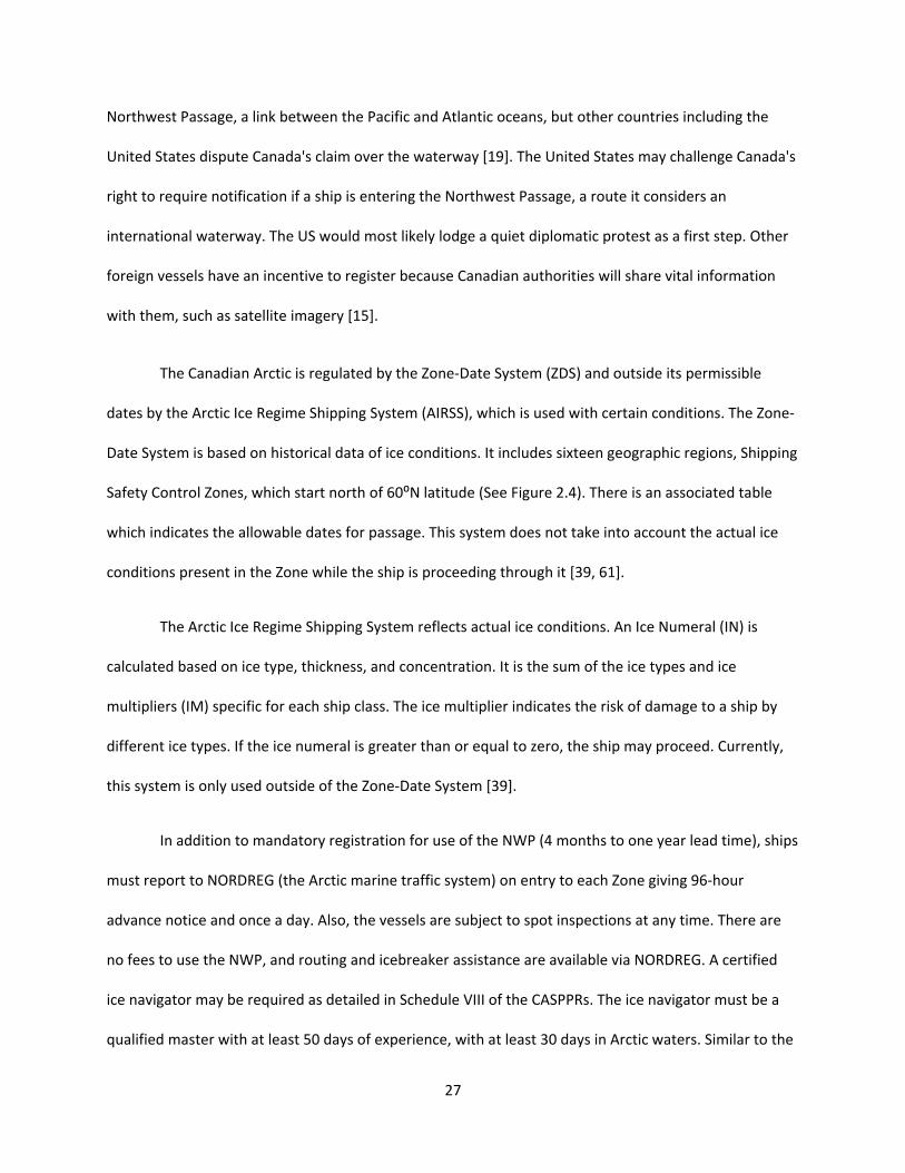
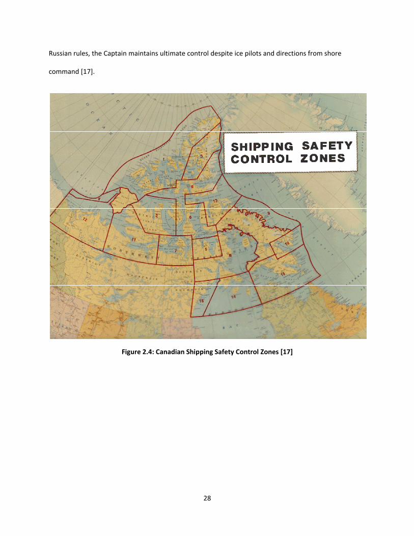
The Canadian Arctic is regulated by the Zone‐Date System (ZDS) and outside its permissible
dates by the Arctic Ice Regime Shipping System (AIRSS), which is used with certain conditions. The Zone‐
Date System is based on historical data of ice conditions. It includes sixteen geographic regions, Shipping
Safety Control Zones, which start north of 60⁰N latitude (See Figure 2.4). There is an associated table
which indicates the allowable dates for passage. This system does not take into account the actual ice
conditions present in the Zone while the ship is proceeding through it [39, 61].
The Arctic Ice Regime Shipping System reflects actual ice conditions. An Ice Numeral (IN) is
calculated based on ice type, thickness, and concentration. It is the sum of the ice types and ice
multipliers (IM) specific for each ship class. The ice multiplier indicates the risk of damage to a ship by
different ice types. If the ice numeral is greater than or equal to zero, the ship may proceed. Currently,
this system is only used outside of the Zone‐Date System [39].
In addition to mandatory registration for use of the NWP (4 months to one year lead time), ships
must report to NORDREG (the Arctic marine traffic system) on entry to each Zone giving 96‐hour
advance notice and once a day. Also, the vessels are subject to spot inspections at any time. There are
no fees to use the NWP, and routing and icebreaker assistance are available via NORDREG. A certified
ice navigator may be required as detailed in Schedule VIII of the CASPPRs. The ice navigator must be a
qualified master with at least 50 days of experience, with at least 30 days in Arctic waters. Similar to the
28
Russian rules, the Captain maintains ultimate control despite ice pilots and directions from shore
command [17].
Figure 2.4: Canadian Shipping Safety Control Zones [17]
29
2.5 DNV Class Rules
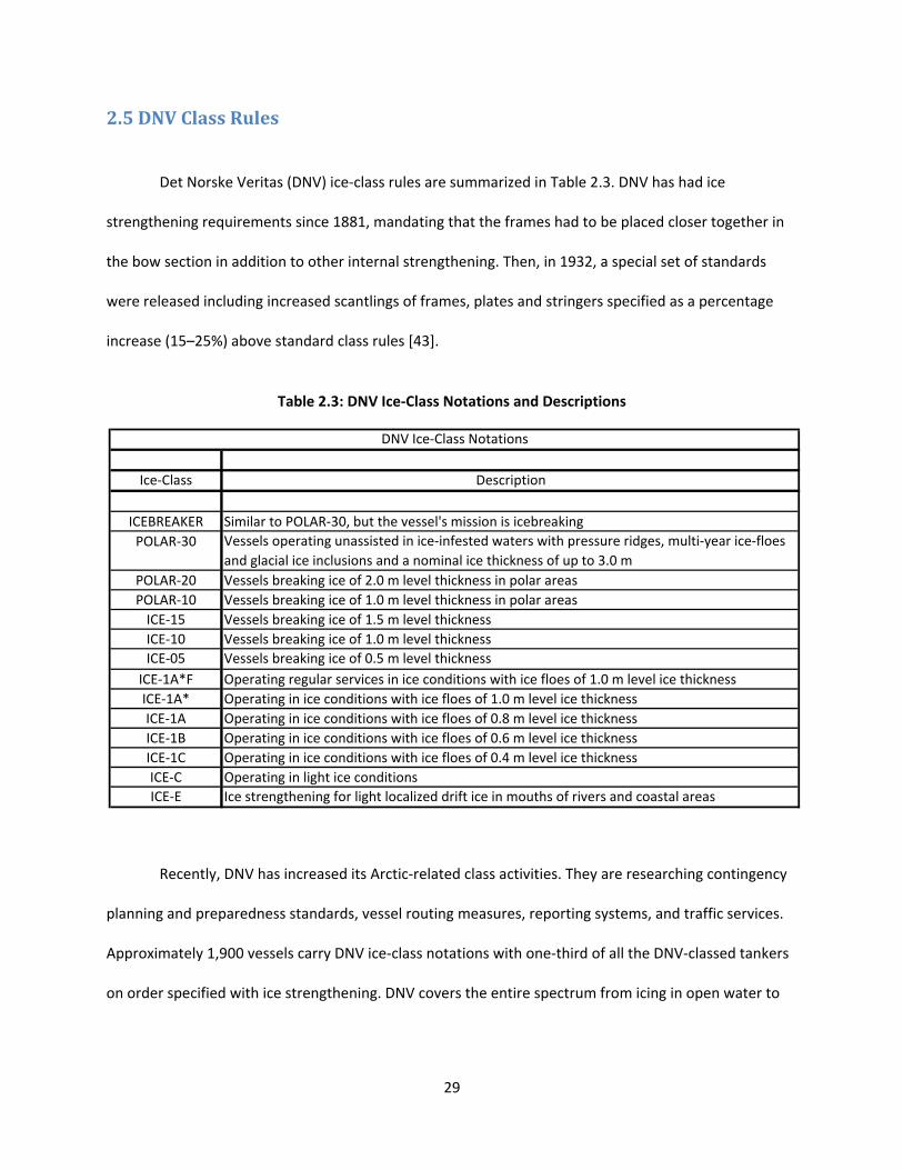
Det Norske Veritas (DNV) ice‐class rules are summarized in Table 2.3. DNV has had ice
strengthening requirements since 1881, mandating that the frames had to be placed closer together in
the bow section in addition to other internal strengthening. Then, in 1932, a special set of standards
were released including increased scantlings of frames, plates and stringers specified as a percentage
increase (15–25%) above standard class rules [43].
Table 2.3: DNV Ice‐Class Notations and Descriptions
Recently, DNV has increased its Arctic‐related class activities. They are researching contingency
planning and preparedness standards, vessel routing measures, reporting systems, and traffic services.
Approximately 1,900 vessels carry DNV ice‐class notations with one‐third of all the DNV‐classed tankers
on order specified with ice strengthening. DNV covers the entire spectrum from icing in open water to
Ice‐Class Description
ICEBREAKER Similar to POLAR‐30, but the vessel's mission is icebreaking
POLAR‐30 Vessels operating unassisted in ice‐infested waters with pressure ridges, multi‐year ice‐floes
and glacial ice inclusions and a nominal ice thickness of up to 3.0 m
POLAR‐20 Vessels breaking ice of 2.0 m level thickness in polar areas
POLAR‐10 Vessels breaking ice of 1.0 m level thickness in polar areas
ICE‐15 Vessels breaking ice of 1.5 m level thickness
ICE‐10 Vessels breaking ice of 1.0 m level thickness
ICE‐05 Vessels breaking ice of 0.5 m level thickness
ICE‐1A*F Operating regular services in ice conditions with ice floes of 1.0 m level ice thickness
ICE‐1A* Operating in ice conditions with ice floes of 1.0 m level ice thickness
ICE‐1A Operating in ice conditions with ice floes of 0.8 m level ice thickness
ICE‐1B Operating in ice conditions with ice floes of 0.6 m level ice thickness
ICE‐1C Operating in ice conditions with ice floes of 0.4 m level ice thickness
ICE‐C Operating in light ice conditions
ICE‐E Ice strengthening for light localized drift ice in mouths of rivers and coastal areas
DNV Ice‐Class Notations
30
icebreaking capabilities in temperatures as low as ‐55⁰C. In addition, optional notations are available,
such as winterization and DEICE (described in more detail in Section 3.5.4.1) [55].
Higher requirements for redundancy and reliability are required for vessels operating alone in
such remote areas. Furthermore, as the traffic increases, there will be less icebreaker support available
unless local governments are increasing icebreaker support by rearranging the existing fleet or by
ordering additional icebreakers.
Also, the increased size of the ships becomes a concern when the width of the vessel is larger
than the width of the icebreaker. Either two icebreakers acting together are required or the vessel will
have to be designed for independent icebreaking. Double‐acting vessels may be a solution (described in
more detail in Section 3.4.2) [43].
DNV also researched an ice load monitoring system that provides bridge personnel with real‐
time information about the actual ice loads on the ship’s hull and shows satellite information about the
ice in the vicinity of the vessel. This system includes fiber optic sensors that measure shear strain on the
vessel’s hull and electromagnetic equipment which measures the thickness of the ice at the bow. This
information is analyzed and displayed on the bridge. Additionally, meteorological and satellite data
about the ice is integrated into electronic charts allowing for optimum route selection. The project is the
first to monitor the actual ice loads and present them in real time at the bridge as a part of a decision
support system. The system is ready to be installed for both new and in‐service ships [56].
2.6 ABS Class Rules
The American Bureau of Shipping has a system of ice classes which includes classes A5 through
A0; B0, C0, and D0. A5 class is the strongest built of the classes, with D0 being the weakest. The Ice Class
Rules are separated into three Chapters.

31
Chapter 1 provides a procedure for ice strengthening of side structures using nonlinear finite
element modeling (FEM), including both side longitudinals and side shell plating. The ice strengthening
procedure involves four steps for alternative design of the side structure under ice load. Table 2.4
summarizes their four steps.
Table 2.4: Steps in Ice Strengthening of Side Structures [2]
The initial design of the side structures should fully comply with FSICR. FSICR require that the
maximum frame spacing of longitudinal frames “shall not exceed 0.35 meter for ice class IA Super and IA
and shall in no case exceed 0.45 meter”. Brackets are required to connect longitudinals and webs. A
more sophisticated method may be substituted to determine the hull scantlings. The reasons a non‐
linear FE model approach would be used are to lower the production costs and to reduce the weight.
The weight of the structure according to direct calculation is normally lower than that required by FSICR
[2].
Chapter 2 provides a procedure for calculating the power requirement for ice‐class ships. The
minimum required engine output power is calculated utilizing the following formula:
/1000 /
where – efficiency of propeller
‐ resistance of the vessesl
32
‐ diameter of the propeller
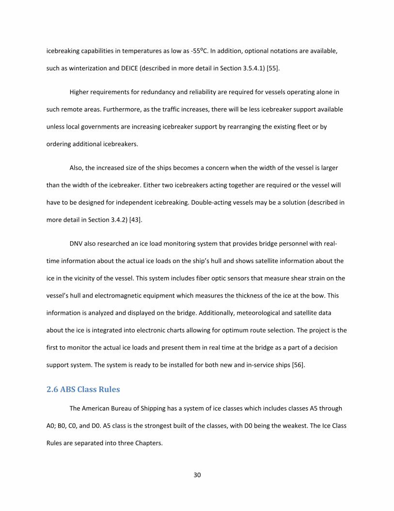
This power requirement is meant to provide the vessel with a minimum speed of 5 knots in the
following ice conditions shown in Table 2.5 [2].
Table 2.5: Performance Requirements [2]
Note: FSICR Notation
Channel thickness = Ice Thickness Consolidated Layer = Thickness of Snow on Top of Ice
Chapter 3 provides a procedure for the strength analysis of propellers for ice class vessels. In
propeller strength assessment, the updated Finnish‐Swedish Ice Class Rules requests that all IA Super
class propellers and highly skewed propellers in IA, IB, and IC classes be subjected to detailed FEM‐based
stress analysis. Technical details regarding the performance of fatigue and plastic failure analysis in the
blade strength assessment procedure are provided [2].
There are two types of interactions between ice and propellers, namely ice milling and ice
impact. Ice milling takes place when an ice block is large or is trapped between the hull and the
propeller. During an instance of milling, ice is either crushed or sheared by the blades, and the loads can
be damagingly high. Ice impact is caused by small‐size ice pieces that are accelerated through a
propeller or thrown out radially and pushed around the edge of the propeller disk. The loads from ice
impact are relatively moderate, but occur more frequently [2].
The material used for the propeller blades of ice class vessels must have high stress and impact
resistance qualities. Stainless steel and bronze are commonly used for ice‐strengthened propeller blades
[2].

33
2.7 Polar Class Rules
There have been efforts to harmonize all of the different ice‐classes into one unified set. The
introduction of the International Association of Classification Societies (IACS) Polar Class Rules is a
significant step in the rule harmonization process. The rules will then have to be adopted by all IACS
members. These rules may be the standard in years to come.
2.7.1 Polar Class Description and Application
The Polar Class Rules consider limited icebreaker assistance and, thus, glancing impact with an
ice floe. These rules are mainly applicable to navigation in multi‐year ice, with the PC1 class capable of
independent operation without limitation. Table 2.6 describes the different Polar Ice Classes.
Table 2.6: Polar Class Descriptions [54]
Polar Class Ice Description (based on WMO Sea Ice Nomenclature).
PC1 Year‐round operation in all Polar waters.
PC2 Year‐round operation in moderate multi‐year ice conditions.
PC3 Year‐round operation in second‐year ice which may include multi‐year ice inclusions.
PC4 Year‐round operation in thick first‐year ice which may include old ice inclusions.
PC5 Year‐round operation in medium first‐year ice which may include old ice inclusions.
PC6 Summer/autumn operation in medium first‐year ice which may include old ice inclusions.
PC7 Summer/autumn operation in thin first‐year ice which may include old ice inclusions.
2.7.2 Structural Requirements for Polar Class Ships
This section of the Polar Class Rules provides structural requirements to enable ships operating
in the Arctic to withstand the effect of ice load and temperature. For ships of all Polar Classes, a glancing
impact on the bow is the design scenario for determining the scantlings required to resist ice loads.
Additionally, global hull girder longitudinal strength analysis is made based on an ice‐ramming scenario.

34
This section also contains material requirements, framing method, corrosion/abrasion allowances, direct
calculations, and welding requirements [20, 54].
2.7.3 Machinery Requirements for Polar Class Ships
This section of the Polar Class Rules includes technical requirements for the main propulsion,
steering gear, emergency and other auxiliary systems essential for the safety of the ship and the
survivability of the crew. It considers the results of research and development on propeller damages,
propeller and shaft load measurements, and propeller‐ice interactions to base its Rules [20, 54].
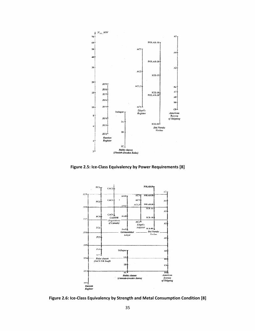
2.8 Equivalencies
The comparison of the different ice‐classes’ rules is a multi‐parametric problem. To make it a
one‐parameter problem, two methods are used: weakest element criterion and averaged
correspondence criterion [8]. The average method is used below since it obtains more objective results.
There are also three different ways to compare ice‐classes: hull structure strength and metal
consumption, power requirements, or both. Figure 2.5 shows the ice‐class equivalencies based on
power requirements while Figure 2.6 shows ice‐class equivalencies based on hull structure strength and
metal consumption.
35
Figure 2.5: Ice‐Class Equivalency by Power Requirements [8]
Figure 2.6: Ice‐Class Equivalency by Strength and Metal Consumption Condition [8]
36
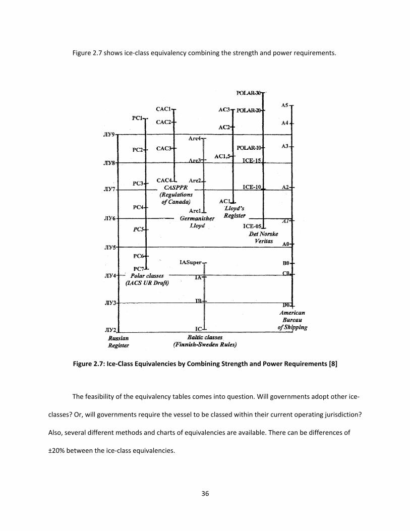
Figure 2.7 shows ice‐class equivalency combining the strength and power requirements.
Figure 2.7: Ice‐Class Equivalencies by Combining Strength and Power Requirements [8]
The feasibility of the equivalency tables comes into question. Will governments adopt other ice‐
classes? Or, will governments require the vessel to be classed within their current operating jurisdiction?
Also, several different methods and charts of equivalencies are available. There can be differences of
±20% between the ice‐class equivalencies.
37
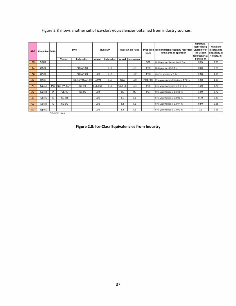
Figure 2.8 shows another set of ice‐class equivalencies obtained from industry sources.
Figure 2.8: Ice‐Class Equivalencies from Industry
Vessel Icebreaker Vessel Icebreaker Vessel Icebreaker A5 CAC1 PC1 Multi-year ice of more than 3.5m 3.25 3.00
A4 CAC2 POLAR-30 LL9 LL1 PC2 Multi-year ice of 3-3.5m 3.00 2.25
A3 CAC3 POLAR-20 LU9 LL8 LL2 PC3 Second year ice of 2-3 m 2.50 1.50
A2 CAC4 ICE-15/POLAR-10 LU7/8 LL7 ULA LL3 PC4-PC5 First-year medium/thick ice of 0.7-2 m 1.50 1.00
A1 Type A IAS ICE-IA*-1A*F ICE-10 LU6/LU5 LL6 ULA-UL LL4 PC6 First-year medium ice of 0.6-1.2 m 1.20 0.70
A0 Type B IA ICE-IA ICE-05 LU4 UL UL PC7 First-year thin ice of 0.5-0.9 m 1.00 0.70
B0 Type C IB ICE-1B LU3 L1 L1 First-year thin ice of 0.3-0.6 m 0.70 0.45
C0 Type D IC ICE-1C LU2 L2 L2 First-year thin ice of 0.3-0.4 m 0.50 0.35
D0 Type E LU1 L3 L3 First-year thin ice of 0.2-0.3 m 0.5 0.25
* Current rules
CanadianABS Proposed
IACS
Minimum Icebreaking Capability at 4 knots, m
Baltic Russian*DNV Russian old rules Ice conditions regularly recorded
in the area of operation
Minimum Icebreaking Capability of the Escort
Icebreaker at 4 knots, m

38
Table 2.7 shows yet another set of ice‐class equivalencies.
Table 2.7: Approximate Equivalence of Class Symbols for Ice Strengthening Between
Classification Societies [20]
Classification Society
Finnish Swedish Ice Class Rules IA Super IA IB IC II
Russian Maritime Register of
Shipping (Rules 1995) UL L1 L2 L3 L4
Russian Maritime Register of
Shipping (Rules 1999) LU5 LU4 LU3 LU2 LU1
American Bureau of Shipping. A1 A0 B0 C0 D0
Bureau Veritas IA Super IA IB IC ID
CASPPR, 1972. A B C D E
China Classification Society. B1* B1 B2 B3 B
Det Norske Veritas ICE‐1A* ICE‐1A ICE‐1B ICE‐1C ICE‐C
Germanischer Lloyd E4 E3 E2 E1 E
Korean Register of Shipping. ISS IS1 IS2 IS3 IS4
Lloyd’s Register of Shipping. 1AS 1A 1B 1C 1D
Nippon Kaiji Kyokai. IA Super IA IB IC ID
Registro Italiano Navale IAS IA IB IC ID
39
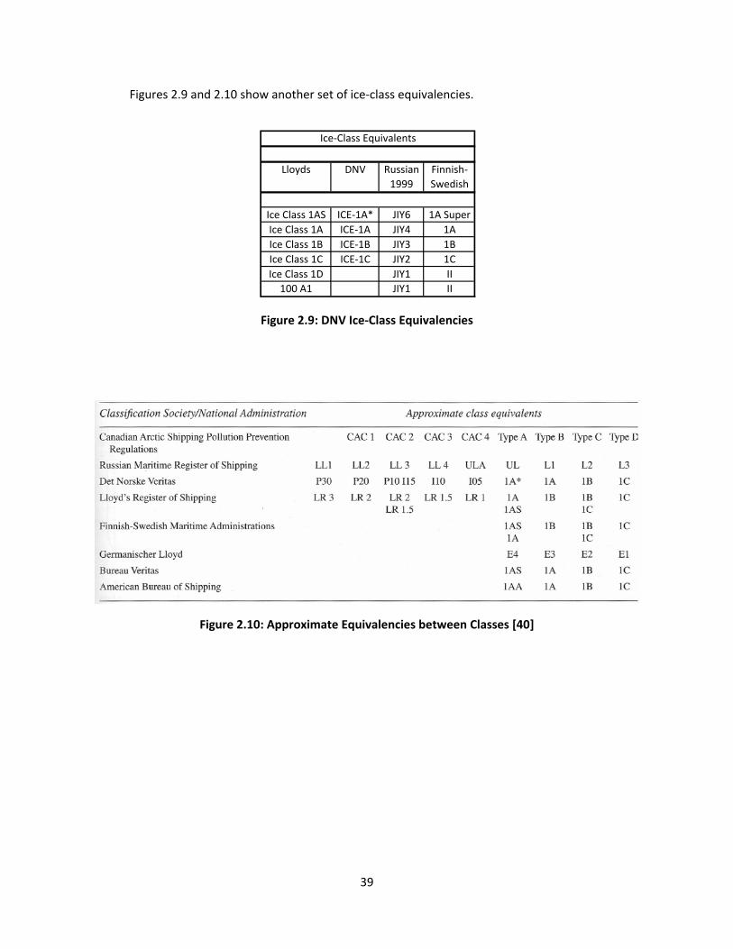
Figures 2.9 and 2.10 show another set of ice‐class equivalencies.
Figure 2.9: DNV Ice‐Class Equivalencies
Figure 2.10: Approximate Equivalencies between Classes [40]
Lloyds DNV Russian Finnish‐
1999 Swedish
Ice Class 1AS ICE‐1A* JIY6 1A Super
Ice Class 1A ICE‐1A JIY4 1A
Ice Class 1B ICE‐1B JIY3 1B
Ice Class 1C ICE‐1C JIY2 1C
Ice Class 1D JIY1 II
100 A1 JIY1 II
Ice‐Class Equivalents

40
Figure 2.11 shows another equivalency table between FSICR and IACS Polar Class rules.
Figure 2.11: Ice‐Class Equivalencies between FSICR and IACS [17]
Several of these ice‐class notations are used in the analysis and discussion of ice‐classing
impacts for containerships in Section 3.5.
41
3.0 Chapter 3: Arctic Containerships
3.1 Introduction
Arctic containerships are significantly different than their conventional (or open water)
counterparts. The design implications of an ice‐classed containership are described as well as a survey of
the current ice‐classed containership fleet. This survey shows the profile of the different ice‐classes, with
the lowest ice‐classes being the most prevalent. The implications of an ice‐classed design are far‐
reaching, from the hull form and structure to the power and auxiliary systems. Then, the Aker study is
examined to obtain baseline sizes for the containerships that are analyzed [6]. The analysis of the
different sized containerships begins in Section 3.5.
3.2 Fleet Survey
Three classification societies’ fleets were analyzed to determine the allocation of the different
ice‐classes. Lloyd’s Registers’ database of ice‐classed containerships was examined and the distribution
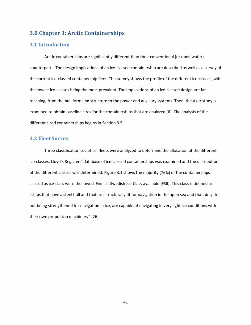
of the different classes was determined. Figure 3.1 shows the majority (76%) of the containerships
classed as ice‐class were the lowest Finnish‐Swedish Ice‐Class available (FSII). This class is defined as
“ships that have a steel hull and that are structurally fit for navigation in the open sea and that, despite
not being strengthened for navigation in ice, are capable of navigating in very light ice conditions with
their own propulsion machinery” [26].
42
Figure 3.1: Lloyd's Register Ice‐Class Fleet (1,350 Containerships)
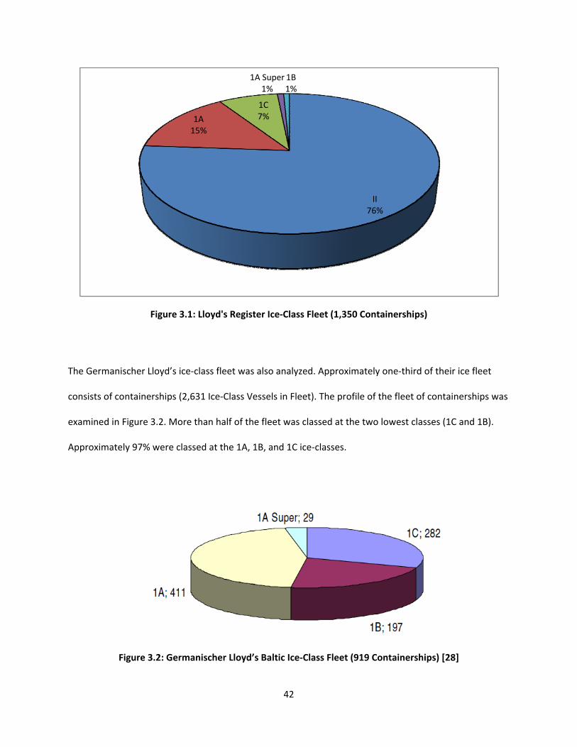
The Germanischer Lloyd’s ice‐class fleet was also analyzed. Approximately one‐third of their ice fleet
consists of containerships (2,631 Ice‐Class Vessels in Fleet). The profile of the fleet of containerships was
examined in Figure 3.2. More than half of the fleet was classed at the two lowest classes (1C and 1B).
Approximately 97% were classed at the 1A, 1B, and 1C ice‐classes.
Figure 3.2: Germanischer Lloyd’s Baltic Ice‐Class Fleet (919 Containerships) [28]
II76%
1A15%
1C7%
1A Super1%
1B1%

43
Finally, DNV’s fleet was studied. Their fleet of containerships was considerably smaller in size
(DNV mostly classes tankers), but similar trends were seen. Figure 3.3 shows the distribution of ice‐
classes. More than 80% of the containerships were classed at the two lowest classes (1C and 1B).
Figure 3.3: DNV’s Containership Fleet Survey (31 Containerships)
1C71%
1A19%
1B10%
DNV Fleet Survey

44
3.3 Impact of IceClass on Vessel Design
Ships whose missions take them into ice‐covered waters must be designed to operate
effectively in an environment distinguished by cold temperatures, remote locations, and the presence of
sea ice. Sea ice can be from a few centimeters to several meters thick, take on a variety of
morphological forms, and change on daily, seasonal, and annual bases [40].
The choice of ice capabilities of the vessel depends on the amount of time spent in ice‐covered
water relative to open water, the ice conditions on the transportation service route, and on the
availability and costs of icebreaker escort services on specific routes. Additionally, operational flexibility
and the second hand market could be factors.
Usually an icebreaker would be expected to achieve about 10 to 12 knots in ice conditions
considered normal in its operating area. In heavier ice conditions, a lower speed, about 6 knots, is
acceptable. The ability to break a given thickness of ice at a minimum continuous speed of about 2 knots
is the usual measure of performance [40].
For most commercial ships, the effects of ice‐classing are incremental: increasing scantlings and
propulsion power leads to a higher capital cost and loss of cargo capacity. But for ships with icebreaking
as their primary mission, ice has a more fundamental impact on design.
3.3.1 Hull Form
3.3.1.1 General Arrangements
The general arrangements of ice‐going vessels can vary widely due to their diverse missions.
Since the ports in the Arctic are usually remote, vessels may carry their own cargo handling gear. Also,
endurance is a factor, so tank capacities and storage for spares and provisions are more important than
for a conventional vessel. The extreme cold and darkness call for several other amenities not commonly
45
found on ships: more interior access ways and equipment operating spaces, adequate heating,
insulation, air conditioning, and extra lighting. Additionally, the noise and vibration from icebreaking
should be kept in mind when designing accommodation spaces.
Escort icebreakers typically have a clear deck aft to accommodate towing operations. This can
include a stern notch. Also, helicopters are usually carried on‐board icebreakers, so a helicopter deck is
needed. Most importantly, the bridge needs to have excellent visibility in all directions.
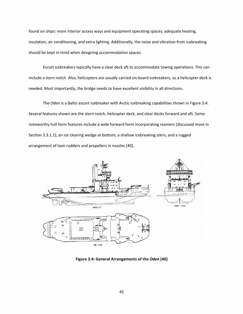
The Oden is a Baltic escort icebreaker with Arctic icebreaking capabilities shown in Figure 3.4.
Several features shown are the stern notch, helicopter deck, and clear decks forward and aft. Some
noteworthy hull form features include a wide forward form incorporating reamers (discussed more in
Section 3.3.1.2), an ice clearing wedge at bottom, a shallow icebreaking stern, and a rugged
arrangement of twin rudders and propellers in nozzles [40].
Figure 3.4: General Arrangements of the Oden [40]

46
3.3.1.2 Shape
The design of the hull form for an icebreaking vessel is a compromise between icebreaking and
open water performance. The appropriate balance is determined specifically for each ship’s mission.
Improved icebreaking performance usually comes at the expense of open water resistance and
seakeeping.
To break level ice effectively, the bow form should promote flexural failure instead of crushing.
This means a shallow stem, buttock, and flare angles. This form also eases the submergence of the ice.
To promote good ice clearance, shallow waterlines and a fine fore body should be utilized. However it is
difficult to reconcile a good icebreaking form with superior ice clearing. The progress of all vessels is
impeded in ice‐clogged channels, but those with shallow bow angles and relatively blunt fore bodies
tend to suffer the most. Shallow refers to small buttock and flare angles. Figure 3.5 shows these bow
form characteristics.
Figure 3.5: Bow Form Characteristics [40]

47
A bulbous bow is probably not appropriate for icebreaking. A bulb is not effective in breaking
ice, has poor clearing attributes, and presents difficulties for some towing arrangements.
Clearing is particularly important when navigating in very close thick pack ice or in brash ice‐
clogged channels. Submerged ice can accumulate at the bow and impede or stop progress. Additionally,
these ice pieces can slide along the entire length and reemerge along the buttocks leading to the
propeller. Propeller‐ice interactions can severely hinder propulsion performance. To deal with this, a
clearing wedge can be incorporated into the hull to promote clearing to the sides. This feature can be
seen in Figures 3.4, 3.5, and 3.6.
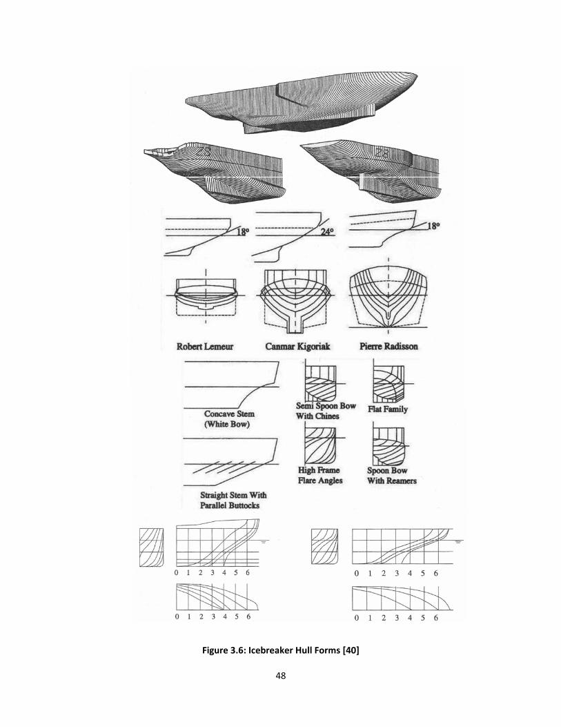
To prevent the vessel from becoming beached during aggressive ramming of ridges and thick ice
floes, an ice skeg (or foot) can be fit to the bow to limit the extent to which the vessel can ride up on the
ice feature (See Figures 3.4, 3.5, and 3.6). Figure 3.6 shows several examples of icebreaking hull shapes.
48
Figure 3.6: Icebreaker Hull Forms [40]
49
For conventional icebreakers, a gradual transition from the bow to the midbody is usually
employed. This avoids excessive crushing at the shoulders during forward icebreaking and maneuvering.
Some icebreakers have sloped sides (about 8⁰ from vertical) along the midbody to provide some force
for the ice to fail in bending rather than crushing. This can improve maneuvering where the midbody
comes into contact with the ice, but can complicate the internal structure [40].
Frictional resistance (from both water and ice) can be kept to a minimum with a good bow form,
which breaks a channel wide enough for the rest of the vessel to pass through. Some icebreakers have
bows that include reamers, so that the bow is wider than the midbody (See Figure 3.4).
The design of an icebreaker’s stern is driven by the required icebreaking capabilities, the
propulsion system (conventional shafting vs. Z‐drives or Azipods, single, twin, or triple screw, and open
or ducted propellers), and the protection of the propulsion gear. The stern also has shallow buttocks at
the waterline for reverse icebreaking. Reamers in the bow are a disadvantage when operating in reverse
and some auxiliary systems, such as a water wash (described in Section 3.3.3) system, can be used to
mitigate this disadvantage [40].
Several methods have been used to protect rudders and propellers from ice. Ice knives aft of the
rudders are intended to deflect and split ice floes when operating in reverse. They are also used to
prevent the ship from excessive ride up on an ice feature, like the ice skeg on the bow.
The importance of bow shape can be seen by analyzing the characteristics of three different
bow shapes for two different ice‐classes as shown in Table 3.1. The table compares two ice‐classes to
the open water variant. For each ice‐class, three different bow shapes were analyzed. Most of the
additional weight was added in the forward section of the hull (50% to 60% of the extra hull steel). The
effect on power is tremendous. For the 1A Super class, the power ranges from 15MW to 40MW; that’s
almost three times as much power for a change in bow shape.

50
Table 3.1: Effect of Bow Shape on Power [48]
3.3.1.2 Structure
The structure of an ice‐capable ship is designed to resist local loads due to ice contact and global
loads associated with ramming‐type operations. Vibration, caused by icebreaking and high installed
power, is also a consideration. Special steel grades with adequate fracture toughness are used because
of the very low temperatures encountered. To reduce the steel weight, usually higher strength steels
are used, which can complicate the fabrication, especially the welding [40].
Ice loads are very difficult to quantify. Efforts are underway to better predict these loads.
Several full‐scale measurement programs have shed new light on this area of research recently. Using
this data, a nominal uniform average pressure and corresponding load area could be deduced for future
designs [40].
For the speeds used in icebreaking, the ice at the interface fails in a brittle manner and the
contact pressure over a nominal contact area tends to be highly concentrated in relatively small regions
distributed within that area. This causes local ice failure and rapid changes in the locations of the
concentrated high contact pressure. Additionally, the variability of the mechanical properties of ice
(which affect failure) complicates the contact loading phenomena further. There are also interaction
Ice‐Class PB (MW) PB (hp) Aft (t) Midship (t) Forward (t) Total (t) Δ Increase ΔNEW (t)
IA 15.0 20,115 61 261 529 851 4.4% 20,251
22.5 30,173 79 299 583 961 5.0% 20,361
30.0 40,231 93 330 628 1,051 5.4% 20,451
IA Super 15.0 20,115 142 453 605 1,200 6.2% 20,600
27.5 36,878 176 528 698 1,402 7.2% 20,802
40.0 53,641 202 586 770 1,558 8.0% 20,958
Open Water Hull Steel Weight = 19,400 t
51
effects like global body motions due to contact loads and local structural deflection, that influence the
ice loads [40].
An ice load model must capture the magnitudes of the design loads corresponding to full‐scale
experience and the contact areas and pressures reflecting the pressure‐area relationship (the design
pressure is higher for local structural members than for larger structural assemblies).
Lately, a move from using the first yield (elastic limit) as a design criterion to using the large
strength reserve in ductile steel plate due to its plasticity is being incorporated into the design criterion.
Using plastic design criteria, permanent set is acceptable, but rupture is still avoided [40].
Structural failure of the support structure can take the form of bending, shear failure, fracture,
and local buckling and tripping instability. To prevent these failure types, each member must have an
adequate section modulus, shear area, and fracture toughness. When aggressive ramming is part of a
ship’s mission, the deck and bottom stresses due to global bending are kept within permissible limits by
ensuring adequate hull girder section modulus.
Another consideration for a vessel’s structure is brittle fracture. Ice‐capable ships are especially
prone to this condition due to their operating environment (air temperatures of ‐20⁰C to ‐50⁰C and
water temperatures of 0⁰C), their mission (causes high local stresses and intermediate strain), and their
thick plating (increases the number of flaws that can propagate). This has caused the use of high‐
strength steels to become a requirement for most classification societies. The most likely sources of
defects are the weld metal and heat‐affected zone of the base metal [40].
The use of high strength steels is becoming more prevalent in the design of icebreakers. Using
higher strength steel reduces weight and provides flexibility to the designer. In the Oden design (Figure
3.4), high strength and extra high strength steel were extensively used (σY ≈ 355 Mpa and σY ≈ 500 Mpa),

52
which offered shell weight savings of about 18% and 30%, respectively, over conventional steel (σY ≈ 245
Mpa) [40].
The hull can be separated into various sections, depending on the frequency and the severity of
the ice loads. Figure 3.7 shows these respective areas.
Figure 3.7: Ice‐Strengthened Hull Areas [40]
The classification societies usually state maximum design loads that are based on ship‐ice
interaction models that are calibrated with full‐scale measurements. The design loads depend on
displacement and power and are applied to different structural members according to a pressure‐area
relationship. Scantlings are determined using elasto‐plastic design criteria that permit stresses in excess
of yield so that some permanent deformation is acceptable. This leads to thinner plate, bigger frames,
and larger frame spacing over traditional ship structural design methods [40].
3.3.2 Propulsion
The propulsion system for an icebreaker is selected similarly to that of conventional ships. The
selection is based on capital and operating costs, reliability, power to weight ratio, and efficiency.
Additionally, icebreakers need systems that are highly responsive for maneuvering and that can operate
53
effectively even while subjected to repeated, intermittent, high torque loading due to propeller impacts
with ice.
The medium speed diesel engine is the most common type of prime mover used on icebreakers.
They have relatively good power to weight ratios and fuel consumption, with relatively inexpensive fuel,
and are compact and reliable. One drawback is their relatively poor overtorque capability. The
transmission used deals with this deficiency [40].
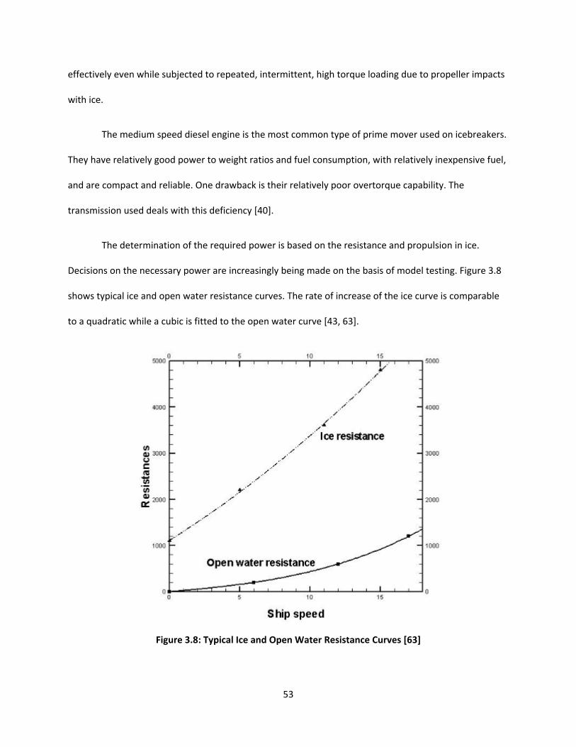
The determination of the required power is based on the resistance and propulsion in ice.
Decisions on the necessary power are increasingly being made on the basis of model testing. Figure 3.8
shows typical ice and open water resistance curves. The rate of increase of the ice curve is comparable
to a quadratic while a cubic is fitted to the open water curve [43, 63].
Figure 3.8: Typical Ice and Open Water Resistance Curves [63]

54
The transmission type is either a geared diesel or a diesel‐electric system. Geared diesels have a
higher efficiency and are lighter, more compact, less costly, and simpler although the ice loads pose
some complications. The high transient ice torque loads necessitate a large flywheel to ensure that the
shaft continues to rotate without a sudden loss of speed when the propeller mills ice. Also, controllable
pitch propellers with a rapid pitch control capability can be used to accommodate high ice torque loads.
Diesel‐electric systems cope better with the ice torque loads by decreasing shaft speed. Diesel‐electric
systems have excellent speed‐torque characteristics and flexibility, in both power output and
arrangement [40].
A single centerline screw on a horizontal shaft is the most common arrangement used on ice
strengthened cargo ships. Most icebreakers have two or three propellers. Multiple propellers offer
redundancy in case of damage, flexible use of power, and enhanced maneuverability. Azimuthing
propellers are becoming popular as they eliminate the need for rudders, shafting, and brackets so the
flow into the propeller is more uniform [40].
The propeller also has to be strengthened for the ice. The extra strength requirements and high
thrust loading results in high strength material, thick blade sections, large blade areas, large hubs, and
little or no rake. Some propellers have the individual blades bolted to the hub, which makes for easier
replacement if one blade is damaged [40]. There are advantages and disadvantages to either fixed pitch
(FPP) or controllable pitch (CPP) propellers. They are related to the machinery commonly used with
each: diesel‐electric for FPP and geared diesel for CPP. To ensure the pitch control for the CPP is
adequately strong and protected, the hub is large (35 to 40% of the propeller diameter). This causes a
loss of efficiency and CPPs are relatively expensive. However, CPPs are good for a vessel that operates
over a wide range of loading conditions and eliminates the need for shaft reversals, thus avoiding low

55
speed and stopped propeller conditions under which a propeller is particularly vulnerable to ice damage.
However, FPPs reverse performance is superior to that of the CPPs.
There are several methods to protect a propeller from ice damage: use a duct, locate the
propeller as close to centerline as possible, reduce the propeller diameter in order to limit torque loads,
use ice deflecting devices, use ice horns and rudders for reverse operation, and for forward operations
use a large skeg or ice wedge. However, all of these devices have drawbacks [40].
3.3.3 Auxiliary Systems
There are a variety of auxiliary systems that are employed to aid the icebreaking process, reduce
resistance, or improve propulsive performance. Low friction paint is one of the simplest. Another
method is an air bubbler system that pumps compressed air at the midbody and bow to reduce
frictional resistance. This system works best at low speeds. A water deluge, or water wash, system
sprays large volumes of water under low pressure on the ice from above the waterline at the bow. This
reduces friction, overburdens the ice, and promotes submergence of ice pieces. Also, heeling tanks are
used to aid in icebreaking and increase maneuverability. By transferring water between the tanks in
rapid succession, the ship can proceed through heavy ice conditions in a ‘duck walk’ (rocking/swaying
motion). All of these systems require power that could be incorporated into the propulsion plant [40].
3.3.4 Operation in Ice
Successful passage through ice‐choked waters depends on the freedom to maneuver. The safety
of the vessel is dependent primarily on the operational aspects (mainly speed) and the structural
capability of the vessel. There are three basic ship handling rules when encountering ice:
‐ Keep moving, even if very slowly.
‐ Work with the ice movement and not against it.
‐ Excessive speed leads to ice damage.
56
Additionally, the severe cold could cause a reduction in the standard operating procedures for radio and
navigational equipment.
The crew will be exposed to continuous freezing temperatures and darkness, which will
deteriorate their performance, thus reducing the safety of the vessel. Each crew member should be
familiar with the signs and treatments of hypothermia. Furthermore, an Ice Navigator should be on
board vessels operating in Arctic ice‐covered waters [20].
3.3.5 Other Requirements
3.3.5.1 Stability
Icebreakers have special stability requirements due to the potential for icing (discussed in
Section 3.5.4.1). Damage stability requirements are also more stringent. In order to ensure safe passage,
there are additional minimum navigation and equipment requirements.
3.3.5.2 Pollution Prevention Provisions
Each classification society and country has a different set of environmental rules. Russia requires
a wastewater treatment facility with a thirty day holding tank. Also, a bilge water separator is mandated
and there are bilge water and garbage discharge restrictions. The vessel must have a double bottom
with no storage of petroleum products. Canada implements a zero‐discharge of water policy (with minor
exceptions). Similarly, there are bilge water discharge restrictions and no pollutants can be stored on the
ship side or bottom [17].
57
3.4 Aker Study Comparison [6]
3.4.1 Overview
Aker Arctic Technology performed the study, “Arctic Shuttle Container Link from Alaska US to
Europe,” in March 2006. In this paper, two containerships were considered: a 750 TEU vessel and a 5000
TEU vessel. One major difference between the 750 TEU and 5000 TEU containerships is the draft. The
larger vessel cannot sail on the coastal route; therefore, it must navigate the Arctic polar pack ice on the
more northern route [6]. Accordingly, the ice conditions are more difficult, increasing her ice
strengthening and power requirements.
3.4.2 Aker’s Double Acting Operation
The double acting concept is patented by Aker. A vessel operates bow first in open water and
light ice conditions and stern first in heavy ice conditions. This allows the bow to be designed to be
efficient in open water, which usually includes a bulb. Also, electric propulsion and azimuthing thrusters
must be adopted. The DAS, ‘Double Acting Stern,’ has no rudder in front of the propellers to impede its
progress. The azimuthing movement of the thrusters makes the reversing steerable, and the ice crushing
effect of the propellers is seen over a wider range, simultaneously enlarging the flushing effect on the
hull surfaces [6].
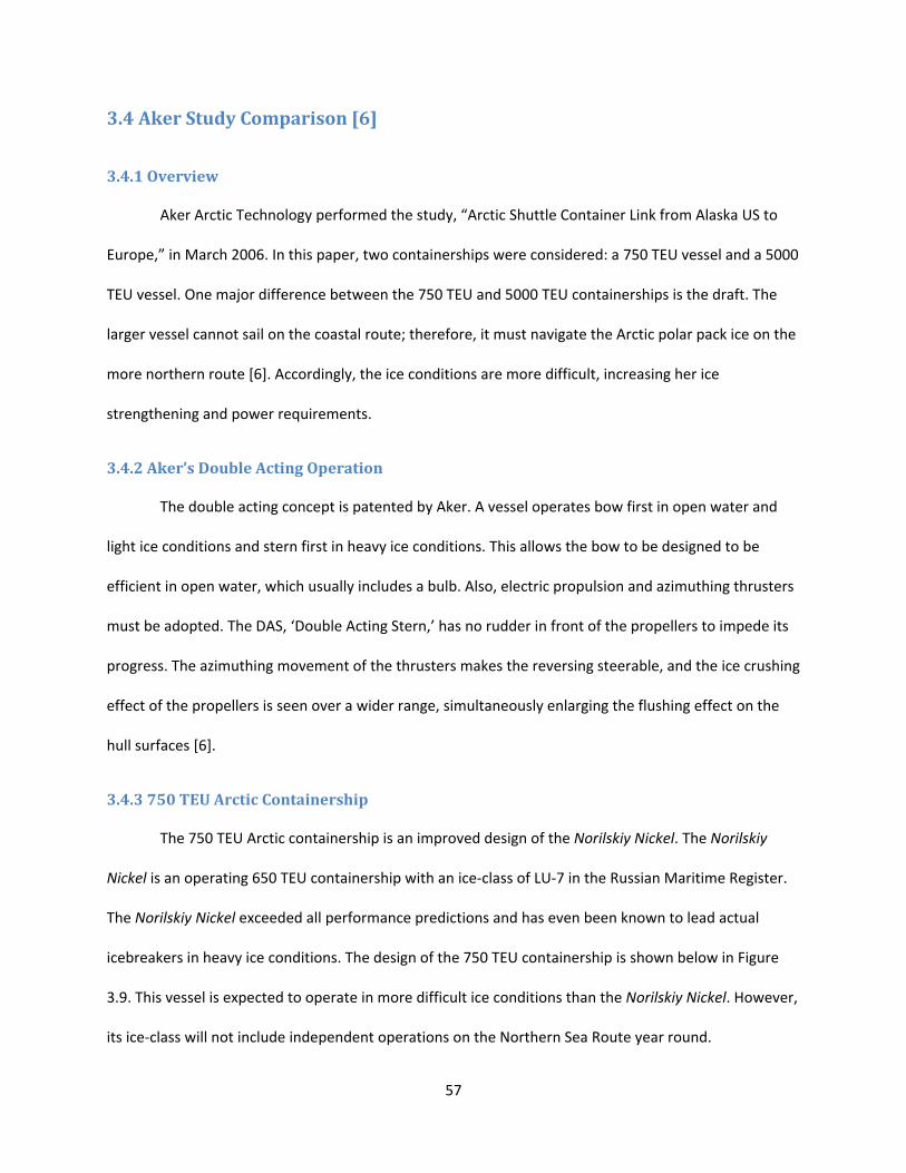
3.4.3 750 TEU Arctic Containership
The 750 TEU Arctic containership is an improved design of the Norilskiy Nickel. The Norilskiy
Nickel is an operating 650 TEU containership with an ice‐class of LU‐7 in the Russian Maritime Register.
The Norilskiy Nickel exceeded all performance predictions and has even been known to lead actual
icebreakers in heavy ice conditions. The design of the 750 TEU containership is shown below in Figure
3.9. This vessel is expected to operate in more difficult ice conditions than the Norilskiy Nickel. However,
its ice‐class will not include independent operations on the Northern Sea Route year round.
58
Figure 3.9: 750 TEU Arctic Containership [6]
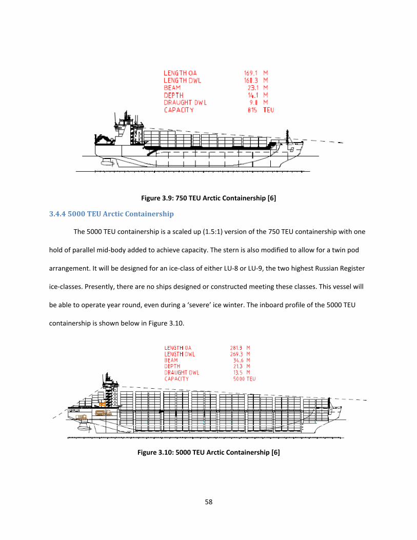
3.4.4 5000 TEU Arctic Containership
The 5000 TEU containership is a scaled up (1.5:1) version of the 750 TEU containership with one
hold of parallel mid‐body added to achieve capacity. The stern is also modified to allow for a twin pod
arrangement. It will be designed for an ice‐class of either LU‐8 or LU‐9, the two highest Russian Register
ice‐classes. Presently, there are no ships designed or constructed meeting these classes. This vessel will
be able to operate year round, even during a ‘severe’ ice winter. The inboard profile of the 5000 TEU
containership is shown below in Figure 3.10.
Figure 3.10: 5000 TEU Arctic Containership [6]
59
The powering of this vessel may be only 70 to 80 percent of its open water counterparts. This is
because open water containerships of this design travel at 22 to 26 knots while the ice‐classed
containership is estimated to achieve 19 knots in open water.
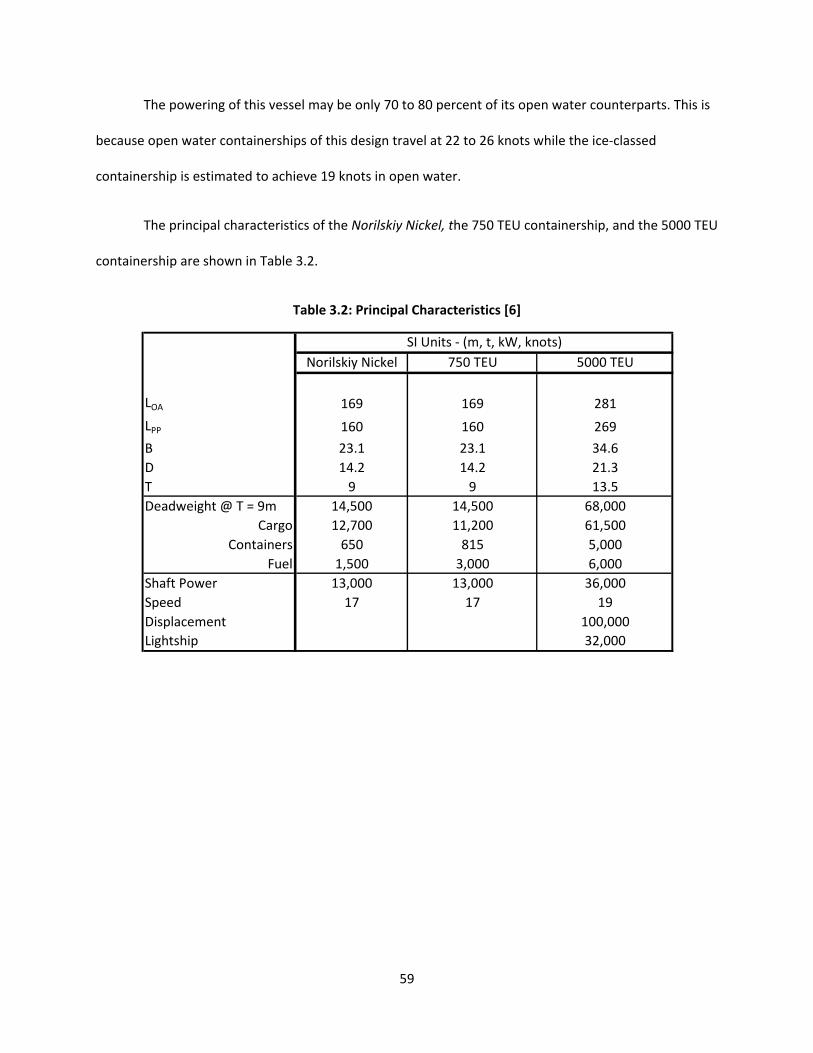
The principal characteristics of the Norilskiy Nickel, the 750 TEU containership, and the 5000 TEU
containership are shown in Table 3.2.
Table 3.2: Principal Characteristics [6]
Norilskiy Nickel 750 TEU 5000 TEU
LOA 169 169 281
LPP 160 160 269
B 23.1 23.1 34.6
D 14.2 14.2 21.3
T 9 9 13.5
Deadweight @ T = 9m 14,500 14,500 68,000
Cargo 12,700 11,200 61,500
Containers 650 815 5,000
Fuel 1,500 3,000 6,000
Shaft Power 13,000 13,000 36,000
Speed 17 17 19
Displacement 100,000
Lightship 32,000
SI Units ‐ (m, t, kW, knots)

60
3.5 Open Water, IceStrengthened, and IceBreaking Containerships
A conventional (or open water) containership, two classes of ice‐strengthened containerships,
and an ice‐breaking containership will be examined in this section.
Detailed industry analyses were reviewed to determine which ice‐class should be used for the
ice‐strengthened containership in this analysis. Although the analysis was not performed specifically for
containerships, comparable sizes and ice‐classes were found and deemed reasonable.
The first ice‐strengthened ship chosen was a compromise between Arctic conditions and open
water. This was to allow greater flexibility of operational area, thus as to not restrict the containership
to only icy waters or to only open water.
This leads to a containership ice‐classed at the ABS A1 or FS 1A‐Super level. These classes have
the ability to operate in first‐year medium ice of 0.6 ‐ 1.2 meters. To meet these requirements an
increase in the lightship of 2% was seen with no additional power being necessary. The increase in
lightship should have a minimal effect on the ship’s operations. Also examined were containerships ice‐
classed at the ABS A3 level (higher ice‐strengthened) and ABS A5 level (independent icebreaker).
The three different ice‐classes will be compared to the open water variant in several areas
relating to cost. First, the increase in weight is analyzed and the effect on the capital cost is found. Then,
the power and fuel consumption are examined and their effect on the operating costs are determined.
3.5.1 Capital Cost
The capital cost of an ice‐classed containership will be higher than a conventional containership.
The hull steel weight will be higher for an ice‐classed vessel, increasing construction costs. Additionally,
several auxiliary systems must be installed on the vessel to enable safe operating in Arctic waters
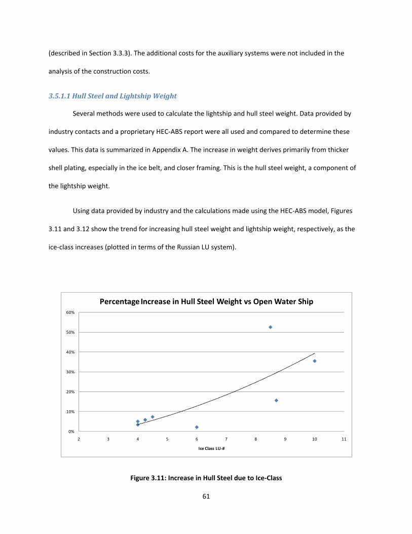
61
(described in Section 3.3.3). The additional costs for the auxiliary systems were not included in the
analysis of the construction costs.
3.5.1.1 Hull Steel and Lightship Weight
Several methods were used to calculate the lightship and hull steel weight. Data provided by
industry contacts and a proprietary HEC‐ABS report were all used and compared to determine these
values. This data is summarized in Appendix A. The increase in weight derives primarily from thicker
shell plating, especially in the ice belt, and closer framing. This is the hull steel weight, a component of
the lightship weight.
Using data provided by industry and the calculations made using the HEC‐ABS model, Figures
3.11 and 3.12 show the trend for increasing hull steel weight and lightship weight, respectively, as the
ice‐class increases (plotted in terms of the Russian LU system).
Figure 3.11: Increase in Hull Steel due to Ice‐Class
0%
10%
20%
30%
40%
50%
60%
2 3 4 5 6 7 8 9 10 11
Ice Class LU‐#
Percentage Increase in Hull Steel Weight vs Open Water Ship

62
Figure 3.12: Increase in Lightship due to Ice‐Class
From the data in Appendix A, it was determined that, in general, a 5% increase in hull steel
weight results in roughly a 3% increase in lightship weight. However, actual data was available and used
for the A1, A3, and A5 ice‐classed containerships.
3.5.1.2 Construction Costs
In order to estimate the relationship between the construction cost and the hull steel weight for
the ice‐class vessels in question, the construction costs of other representative ice‐classed
containerships were determined using the proprietary HEC‐ABS model and industry values. These
representative containerships and their costs are shown in Table 3.3. The ABS D0 class cost was taken
from industry data. For the 5000 TEU vessel, costs were calculated for both the open water and LU‐8 or
LU‐9 ice‐class using the HEC‐ABS model since the parametric model was for larger containerships. This
model breaks the ship’s weight into several categories including: hull steel, coatings, accommodation
outfit, hull outfit and piping, cargo equipment, machinery and electrical, and engineering and fees.
0%
10%
20%
30%
40%
50%
60%
2 3 4 5 6 7 8 9 10 11
Ice Class LU‐#
Percentage Increase in Lightship vs Open Water Ship
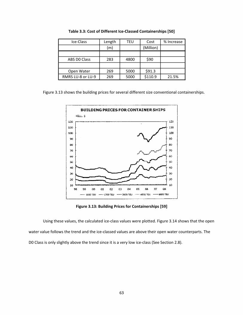
63
Table 3.3: Cost of Different Ice‐Classed Containerships [50]
Figure 3.13 shows the building prices for several different size conventional containerships.
Figure 3.13: Building Prices for Containerships [59]
Using these values, the calculated ice‐class values were plotted. Figure 3.14 shows that the open
water value follows the trend and the ice‐classed values are above their open water counterparts. The
D0 Class is only slightly above the trend since it is a very low ice‐class (See Section 2.8).
Ice‐Class Length TEU Cost % Increase
(m) (Million)
ABS D0 Class 283 4800 $90
Open Water 269 5000 $91.3
RMRS LU‐8 or LU‐9 269 5000 $110.9 21.5%

64
Figure 3.14: Comparison of Open Water and Ice‐Classed Containership Prices [59]
In summary, the data show that for a 10% increase in hull steel weight, cost increases by roughly
4%. This relationship is used in Section 3.5.3 to determine the total cost for the A1, A3, and A5 ice‐
classed containerships.
3.5.2 Operating Costs
The operating costs of an ice‐classed containership will be higher than a conventional
containership. The power and, thus, fuel consumption will be significantly higher for an ice‐classed
vessel, increasing operating costs. Additionally, the crew must have experience operating in ice,
resulting in higher wages (described in Section 3.5.4.2). Also, the insurance costs more for an ice‐classed
vessel for obvious reasons. The additional crew and insurance costs were not included in the analysis of
the operating costs.
0
20
40
60
80
100
120
0 1000 2000 3000 4000 5000 6000 7000
Cost ($ Mil)
TEU
Building Prices for Containerships
D0 Class
LU‐8 or LU‐9
Open Water
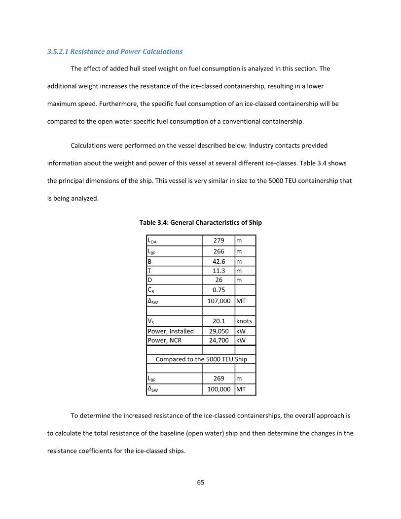
65
3.5.2.1 Resistance and Power Calculations
The effect of added hull steel weight on fuel consumption is analyzed in this section. The
additional weight increases the resistance of the ice‐classed containership, resulting in a lower
maximum speed. Furthermore, the specific fuel consumption of an ice‐classed containership will be
compared to the open water specific fuel consumption of a conventional containership.
Calculations were performed on the vessel described below. Industry contacts provided
information about the weight and power of this vessel at several different ice‐classes. Table 3.4 shows
the principal dimensions of the ship. This vessel is very similar in size to the 5000 TEU containership that
is being analyzed.
Table 3.4: General Characteristics of Ship
To determine the increased resistance of the ice‐classed containerships, the overall approach is
to calculate the total resistance of the baseline (open water) ship and then determine the changes in the
resistance coefficients for the ice‐classed ships.
LOA 279 m
LBP 266 m
B 42.6 m
T 11.3 m
D 26 m
CB 0.75
∆SW 107,000 MT
VS 20.1 knots
Power, Installed 29,050 kW
Power, NCR 24,700 kW
LBP 269 m
∆SW 100,000 MT
Compared to the 5000 TEU Ship
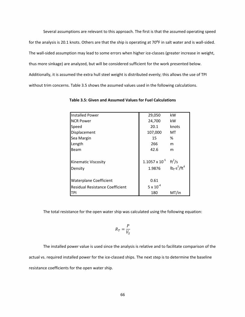
66
Several assumptions are relevant to this approach. The first is that the assumed operating speed
for the analysis is 20.1 knots. Others are that the ship is operating at 70⁰F in salt water and is wall‐sided.
The wall‐sided assumption may lead to some errors when higher ice‐classes (greater increase in weight,
thus more sinkage) are analyzed, but will be considered sufficient for the work presented below.
Additionally, it is assumed the extra hull steel weight is distributed evenly; this allows the use of TPI
without trim concerns. Table 3.5 shows the assumed values used in the following calculations.
Table 3.5: Given and Assumed Values for Fuel Calculations
The total resistance for the open water ship was calculated using the following equation:
The installed power value is used since the analysis is relative and to facilitate comparison of the
actual vs. required installed power for the ice‐classed ships. The next step is to determine the baseline
resistance coefficients for the open water ship.
Installed Power 29,050 kW
NCR Power 24,700 kW
Speed 20.1 knots
Displacement 107,000 MT
Sea Margin 15 %
Length 266 m
Beam 42.6 m
Kinematic Viscosity 1.1057 x 10‐5 ft2/s
Density 1.9876 lbf‐s2/ft4
Waterplane Coefficient 0.61
Residual Resistance Coefficient 5 x 10‐4
TPI 180 MT/in
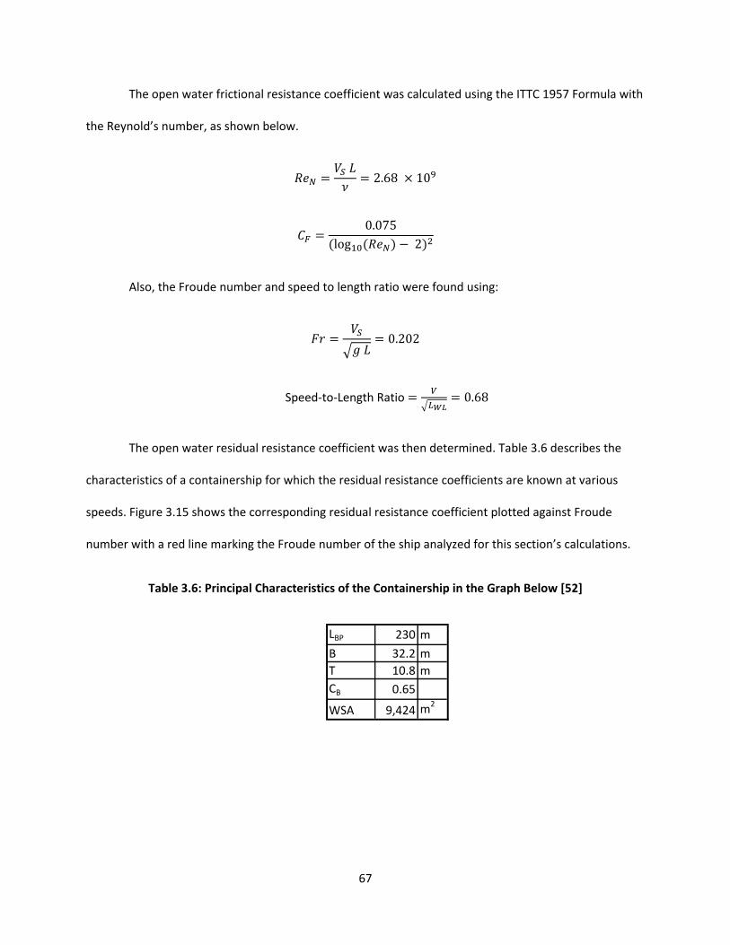
67
The open water frictional resistance coefficient was calculated using the ITTC 1957 Formula with
the Reynold’s number, as shown below.
2.68 10
0.075log 2
Also, the Froude number and speed to length ratio were found using:
0.202
Speed‐to‐Length Ratio 0.68
The open water residual resistance coefficient was then determined. Table 3.6 describes the
characteristics of a containership for which the residual resistance coefficients are known at various
speeds. Figure 3.15 shows the corresponding residual resistance coefficient plotted against Froude
number with a red line marking the Froude number of the ship analyzed for this section’s calculations.
Table 3.6: Principal Characteristics of the Containership in the Graph Below [52]
LBP 230 m
B 32.2 m
T 10.8 m
CB 0.65
WSA 9,424 m2

68
Figure 3.15: Experimental Dependence of Residual Resistance Coefficient on Froude Number [52]
After reviewing the various sources [52, 64, 31] and Figure 3.15, a residual resistance coefficient
of 5 x 10‐4 was used for the open water vessel in the calculations.
Next, the total resistance coefficient for the open water ship was determined, using the
following equation:
Since the change in resistance was examined, a correlation allowance was not used since it
would drop out.
The wetted surface area of the open water ship was caluclated, using the following equation:
12
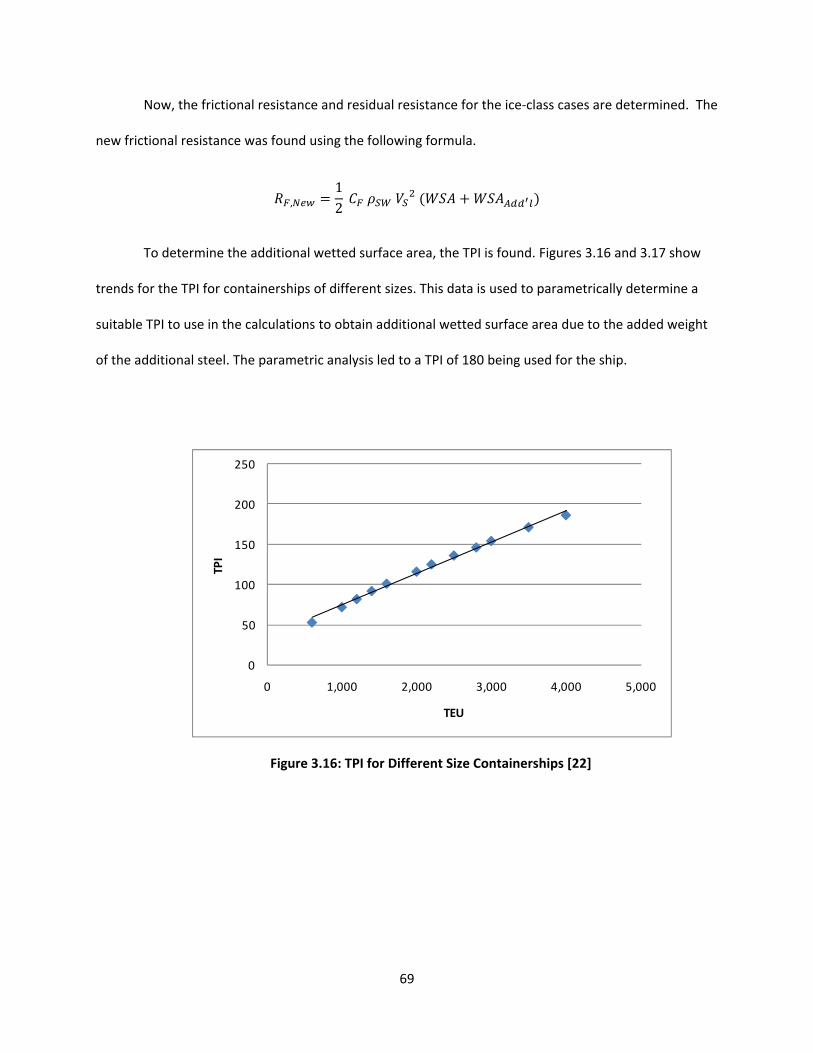
69
Now, the frictional resistance and residual resistance for the ice‐class cases are determined. The
new frictional resistance was found using the following formula.
,12
To determine the additional wetted surface area, the TPI is found. Figures 3.16 and 3.17 show
trends for the TPI for containerships of different sizes. This data is used to parametrically determine a
suitable TPI to use in the calculations to obtain additional wetted surface area due to the added weight
of the additional steel. The parametric analysis led to a TPI of 180 being used for the ship.
Figure 3.16: TPI for Different Size Containerships [22]
0
50
100
150
200
250
0 1,000 2,000 3,000 4,000 5,000
TPI
TEU
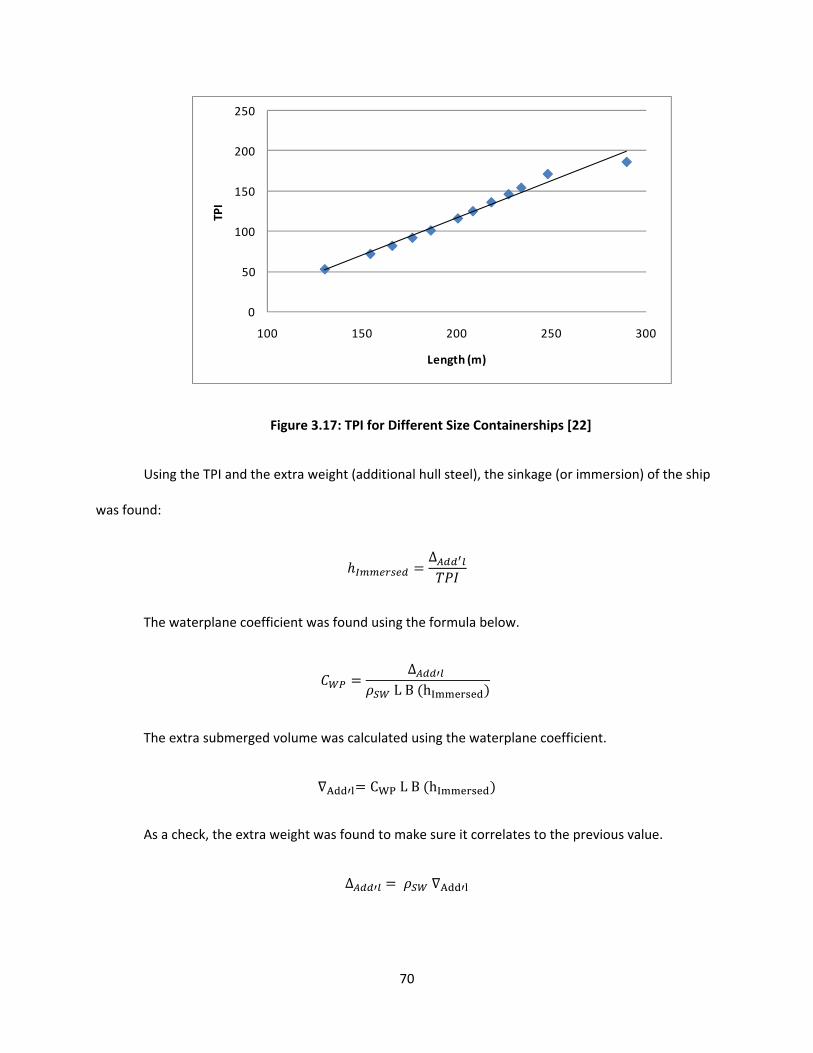
70
Figure 3.17: TPI for Different Size Containerships [22]
Using the TPI and the extra weight (additional hull steel), the sinkage (or immersion) of the ship
was found:
∆
The waterplane coefficient was found using the formula below.
∆ L B hI
The extra submerged volume was calculated using the waterplane coefficient.
A CWP L B hI
As a check, the extra weight was found to make sure it correlates to the previous value.
∆ A
0
50
100
150
200
250
100 150 200 250 300
TPI
Length (m)
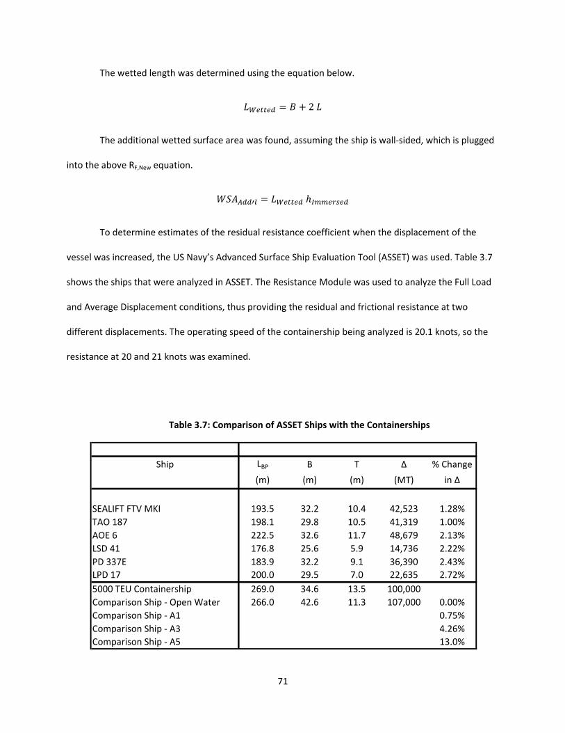
71
The wetted length was determined using the equation below.
2
The additional wetted surface area was found, assuming the ship is wall‐sided, which is plugged
into the above RF,New equation.
To determine estimates of the residual resistance coefficient when the displacement of the
vessel was increased, the US Navy’s Advanced Surface Ship Evaluation Tool (ASSET) was used. Table 3.7
shows the ships that were analyzed in ASSET. The Resistance Module was used to analyze the Full Load
and Average Displacement conditions, thus providing the residual and frictional resistance at two
different displacements. The operating speed of the containership being analyzed is 20.1 knots, so the
resistance at 20 and 21 knots was examined.
Table 3.7: Comparison of ASSET Ships with the Containerships
Ship LBP B T ∆ % Change
(m) (m) (m) (MT) in ∆
SEALIFT FTV MKI 193.5 32.2 10.4 42,523 1.28%
TAO 187 198.1 29.8 10.5 41,319 1.00%
AOE 6 222.5 32.6 11.7 48,679 2.13%
LSD 41 176.8 25.6 5.9 14,736 2.22%
PD 337E 183.9 32.2 9.1 36,390 2.43%
LPD 17 200.0 29.5 7.0 22,635 2.72%
5000 TEU Containership 269.0 34.6 13.5 100,000
Comparison Ship ‐ Open Water 266.0 42.6 11.3 107,000 0.00%
Comparison Ship ‐ A1 0.75%
Comparison Ship ‐ A3 4.26%
Comparison Ship ‐ A5 13.0%

72
Table 3.8 shows the percentage change in residual resistance due to a percentage change in
displacement.
Table 3.8: Effect of Changing Displacement on Residual Resistance
After analyzing the ASSET data, the relationship identified was that the residual resistance
coefficient increased by 50% of the displacement increase. For example, if the displacement increased
10%, the residual resistance coefficient was increased 5%.
The total resistance was then determined for each ice‐class case, using the following equation:
, , ,
Then the new required power for each ice‐class was found, using the equation below.
,
Ship % Change % Change %RR / %∆ % Change % Change %RR / %∆
in RR in RF in RR in RF
SEALIFT FTV MKI 0.73% 0.56% 57.0% 0.68% 0.56% 53.3%
TAO 187 0.67% 0.62% 66.8% 0.74% 0.62% 74.3%
AOE 6 1.23% 1.16% 57.9% 1.29% 1.15% 60.7%
LSD 41 0.40% 1.03% 18.0% 1.13% 1.04% 51.1%
PD 337E 0.62% 1.33% 25.4% 0.23% 1.33% 9.6%
LPD 17 1.67% 1.61% 61.3% 0.93% 1.60% 34.1%
20 knots 21 knots

73
Tables 3.9 and 3.10 show the results of the calculations outlined above. The installed power is
the power installed on the icebreaking ships, while the required power is that power required to
maintain the 20.1 knots (operating speed) in open water.
Table 3.9: Change in Draft with Differing Ice‐Classes
Table 3.10: Change in Power with Differing Ice‐Classes
As an aside, the installed power for the A5 class is reasonable even though it is over 230%
greater than the power required to maintain the open water speed. The most powerful icebreaker in the
world has two nuclear reactors which develop approximately 500,000 horsepower (≈360,000 kW), and
has a huge steel ice belt 5 meters wide that can easily break through ice up to 2.5 meters thick [33].
Ice‐Class Increase in % Increase % Increase Immersion New
LS Weight in Lightship in Overall Draft
(ABS) (MT) Weight Weight (in) (m)
A1 800 2.78% 0.75% 4.44 11.41
A3 4,557 13.7% 4.3% 25.3 11.94
A5 13,892 48.2% 13.0% 77.2 13.26
Open ‐ 28,800 MT 107,000 MT ‐ 11.3 m
Ice‐Class New Power % Increase Installed % Increase
Required to in Power Power Installed over
(ABS) Maintain Speed to Maintain Required Power
(kW) Speed (kW)
A1 29,129 0.27% 29,050 ‐0.27%
A3 29,501 1.55% 41,845 41.8%
A5 30,424 4.73% 102,370 236%
Open 29,050 kW ‐ 29,050 kW ‐
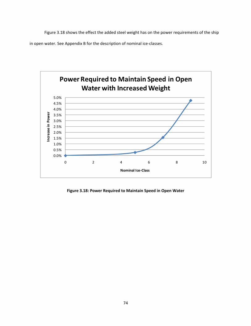
74
Figure 3.18 shows the effect the added steel weight has on the power requirements of the ship
in open water. See Appendix B for the description of nominal ice‐classes.
Figure 3.18: Power Required to Maintain Speed in Open Water
0.0%
0.5%
1.0%
1.5%
2.0%
2.5%
3.0%
3.5%
4.0%
4.5%
5.0%
0 2 4 6 8 10
Increase in Power
Nominal Ice‐Class
Power Required to Maintain Speed in Open Water with Increased Weight

75
Figure 3.19 shows the decrease in speed as the weight increases if the power isn’t changed. For
the highest ice‐class, the maximum open water speed decreases about one knot.
Figure 3.19: Difference in Speed with Increased Weight
19.00
19.20
19.40
19.60
19.80
20.00
20.20
0 2 4 6 8 10
Speed (kn
ots)
Nominal Ice‐Class
Change in Speed with the Increased Weight

76
Figure 3.20 shows both the installed and required power for the ship over the three different
ice‐classes and open water. For the A3 ice‐class, about 1.4 times the power was installed on the ship and
for the A5 ice‐class, about 3.4 times the required power was installed. This extra power is installed as
part of the ice‐class rules (stating a minimum power) and includes several factors of safety. Also, towing
is usually part of an icebreaker’s mission, which substantially increases the installed power. This aspect
was not taken into account in these calculations; only the power necessary to maintain the given
operating speed was found.
Figure 3.20: The Installed Power and Required Power for Differing Ice‐Classes
25,000
35,000
45,000
55,000
65,000
75,000
85,000
95,000
105,000
0 1 2 3 4 5 6 7 8 9 10
Power (kW)
Nominal Ice‐Class
Installed vs Required Power
Installed Required

77
3.5.2.2 Fuel Consumption Calculations
Next, the fuel consumptions were calculated for the open water and the three different ice‐
classed ships. First, an average fuel consumption for an open water containership was found using
various sources.
Figure 3.21 shows an average specific fuel consumption of 135 g/bhp‐hr, which is equivalent to
181 g/kW‐hr.
Figure 3.21: Specific Fuel Consumption Over Time [30]
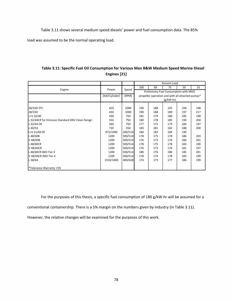
78
Table 3.11 shows several medium speed diesels’ power and fuel consumption data. The 85%
load was assumed to be the normal operating load.
Table 3.11: Specific Fuel Oil Consumption for Various Man B&W Medium Speed Marine Diesel
Engines [21]
For the purposes of this thesis, a specific fuel consumption of 180 g/kW‐hr will be assumed for a
conventional containership. There is a 5% margin on the numbers given by industry (in Table 3.11).
However, the relative changes will be examined for the purposes of this work.
100 85 75 50 25
(kW/Cylinder) (RPM)
28/33D STC 420 1000 190 188 192 194 198
28/33D 450 1000 190 188 189 197 217
L+V 32/40 500 750 181 179 180 185 198
L 32/44CR for Emission Standard DNV Clean Design 550 750 180 178 185 190 204
L 32/44 CR 560 750 177 175 179 184 197
L 40/54 720 550 183 181 182 188 200
L+V 51/60 DF 975/1000 500/514 184 183 184 190
L 48/60B 1200 500/514 178 175 178 186 203
V 48/60B 1200 500/514 176 173 176 184 201
L 48/60CR 1200 500/514 178 175 178 183 190
V 48/60CR 1200 500/514 176 173 176 181 197
L 48/60CR IMO Tier II 1200 500/514 180 176 180 185 201
V 48/60CR IMO Tier II 1200 500/514 178 174 178 183 199
L 58/64 1310/1400 400/428 174 173 177 186 199
*Tolerance Warranty +5%
Percent Load
Preliminary Fuel Consumption with MGO
propeller operation and with all attached pumps*
(g/kW‐hr)
Engine Power Speed
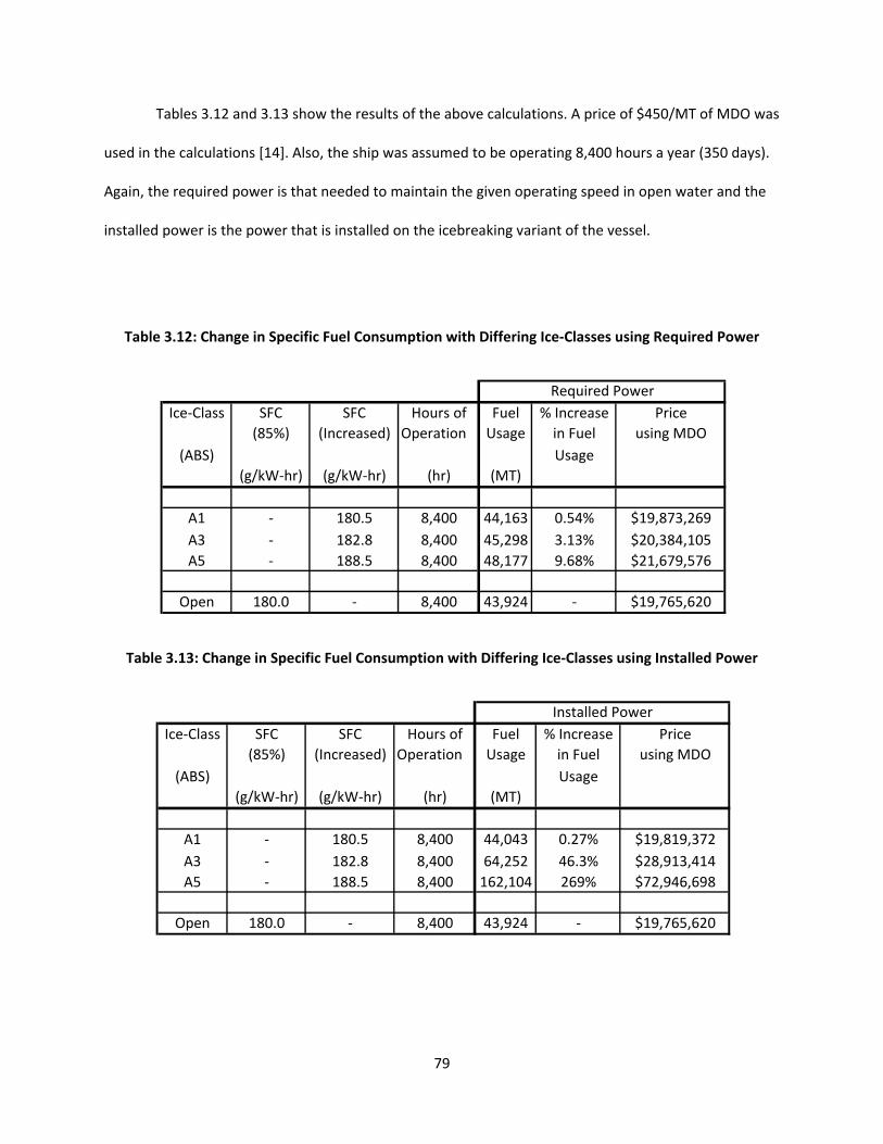
79
Tables 3.12 and 3.13 show the results of the above calculations. A price of $450/MT of MDO was
used in the calculations [14]. Also, the ship was assumed to be operating 8,400 hours a year (350 days).
Again, the required power is that needed to maintain the given operating speed in open water and the
installed power is the power that is installed on the icebreaking variant of the vessel.
Table 3.12: Change in Specific Fuel Consumption with Differing Ice‐Classes using Required Power
Table 3.13: Change in Specific Fuel Consumption with Differing Ice‐Classes using Installed Power
Ice‐Class SFC SFC Hours of Fuel % Increase Price
(85%) (Increased) Operation Usage in Fuel using MDO
(ABS) Usage
(g/kW‐hr) (g/kW‐hr) (hr) (MT)
A1 ‐ 180.5 8,400 44,163 0.54% $19,873,269
A3 ‐ 182.8 8,400 45,298 3.13% $20,384,105
A5 ‐ 188.5 8,400 48,177 9.68% $21,679,576
Open 180.0 ‐ 8,400 43,924 ‐ $19,765,620
Required Power
Ice‐Class SFC SFC Hours of Fuel % Increase Price
(85%) (Increased) Operation Usage in Fuel using MDO
(ABS) Usage
(g/kW‐hr) (g/kW‐hr) (hr) (MT)
A1 ‐ 180.5 8,400 44,043 0.27% $19,819,372
A3 ‐ 182.8 8,400 64,252 46.3% $28,913,414
A5 ‐ 188.5 8,400 162,104 269% $72,946,698
Open 180.0 ‐ 8,400 43,924 ‐ $19,765,620
Installed Power
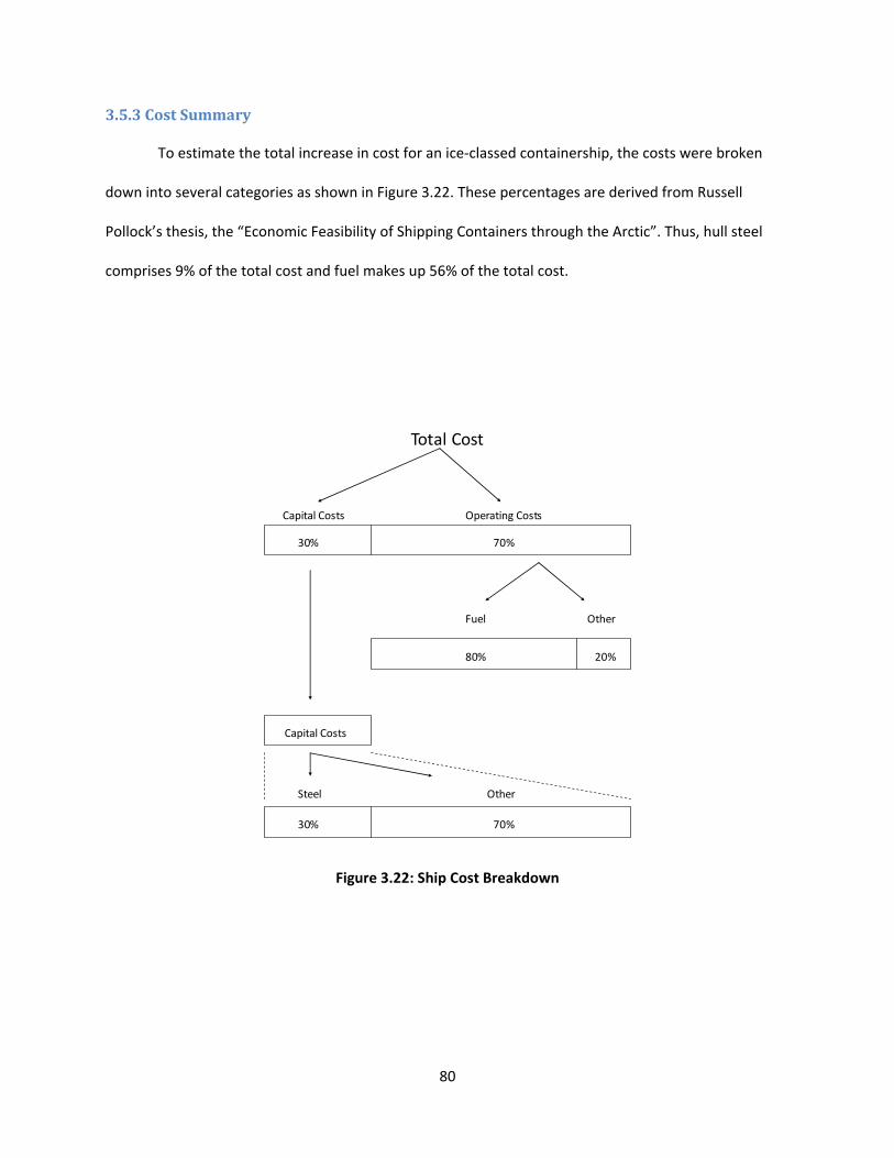
80
3.5.3 Cost Summary
To estimate the total increase in cost for an ice‐classed containership, the costs were broken
down into several categories as shown in Figure 3.22. These percentages are derived from Russell
Pollock’s thesis, the “Economic Feasibility of Shipping Containers through the Arctic”. Thus, hull steel
comprises 9% of the total cost and fuel makes up 56% of the total cost.
Figure 3.22: Ship Cost Breakdown
Total Cost
Capital Costs Operating Costs
30% 70%
Fuel Other
80% 20%
Steel Other
30% 70%
Capital Costs

81
Table 3.14 shows the effect of different ice‐classes on the weight, power, fuel consumption, and cost of
containerships.
Table 3.14: Overall Summary of Ice‐Class Differences
As seen, the increases in installed power have the greatest impact on total cost, particularly for
the A3 and A5 ice‐classes.
3.5.4 Other Cost Considerations
3.5.4.1 Icing
An ice‐classed ship needs to have many additional features. An ANTI‐ICE class notation can be
achieved if several criteria are met. These deal primarily with the prevention of icing of ship structures
and equipment: including anchor and mooring equipment, lifeboat hook releasing devices, survival craft
launching arrangements, liferafts, special Arctic foam for firefighting, pre‐heated combustion air,
insulation, defrosters for navigation‐related areas on deck, use of special ice‐resistant materials, and
special cold‐weather outfits for the crew [57, 58]. The steel above the waterline is exposed to harsh
conditions including temperatures around ‐40⁰C. Sonar and helicopters (electromagnetic imaging for
icebergs) can also be used to detect current ice conditions.
Percentage Increase over Open WaterA1 (FS 1A-Super) A3 A5 (PC1)
Weight (Lightship) 2.8% 15.8% 48.2%Weight (Hull Steel) 2.7% 15.5% 35.4%Power (Installed) -0.3% 41.8% 236%Power (Required) 0.27% 1.55% 4.73%
Fuel Consumption (Installed) 0.27% 46.3% 269%Fuel Consumption (Required) 0.54% 3.13% 9.68%
Cost - Steel 1.1% 6.20% 14.1%Cost - Fuel 0.27% 46.3% 269%Cost - Total 0.25% 26.5% 152%
Note: Installed - Power installed on the icebreaking variant of the vessel to satisfy the higher
power demand (ice-breaking or max speed). Required - Power needed to maintain the given operating speed in open water.
Ice-Class
82
DNV has a similar notation to provide additional protection in the Arctic. The DEICE notation
provides operational safety through proactive preparation. The ship has to be outfitted with de‐icing
equipment to remove ice within a period of 4‐6 hours. It is important to keep certain areas where
continuous operation is required, such as navigational equipment and fire lines, ice‐free. If this
equipment becomes ice‐covered, the level of safety decreases substantially [43].
Icing usually leads to several problems including the impairment of stability due to the lifted
center of gravity, the limitation on safe navigation caused by antenna and radar equipment being out of
operation, and icing on wheelhouse windows. In addition, liferaft release mechanisms may become
jammed, scuppers can clog, and gangways and railings are unsafe to use.
All of these extras, increasing a ship’s capability to operate in the Arctic, lead to an increase in
cost. Additionally, supplemental insurance is usually required for operations in the Arctic. There has
been an increase in the number of ice‐related claims. Usually the ice damage is a small incident that
turns into a major claim because of the remoteness of the location [46].
Ice navigation poses additional stability issues. The ship is subject to movements from ramming
and ice impacts as it moves through the ice. Also, damage stability criteria must be able to withstand
flooding resulting from hull penetration due to ice damage, and to return the ship to equilibrium after
such damage. When hot cargoes are carried, a thermal stress is created in the hull, so the permissible
still water bending moments should be reduced. Additionally, rapid icing can occur since large quantities
of sea spray hit the ship. This can result in topside ice accumulations of over 10cm. This may adversely
affect the ship’s stability [20].

83
When navigating in the Russian Arctic, an Ice Certificate is required. There are also different
rules in effect, for example, the ‘sanitary rules’, which include requirements for noise, vibration and
ventilation [43].
3.5.4.2 Crew
When a vessel is operating in ice, the major increase in noise and vibration will affect the crew’s
ability to get proper rest when off duty, and thus reduce their ability to work safely while on duty. There
is research underway to improve human performance in cold and dark conditions. The skill and
experience of the crew will prove to have a significant and direct impact on the safety level.
Furthermore, most ship operations are different in ice and low temperatures and require experienced
crews in order to maintain the same safety level as for worldwide operations. Unavailability of
competent crews may limit safe operation [43].
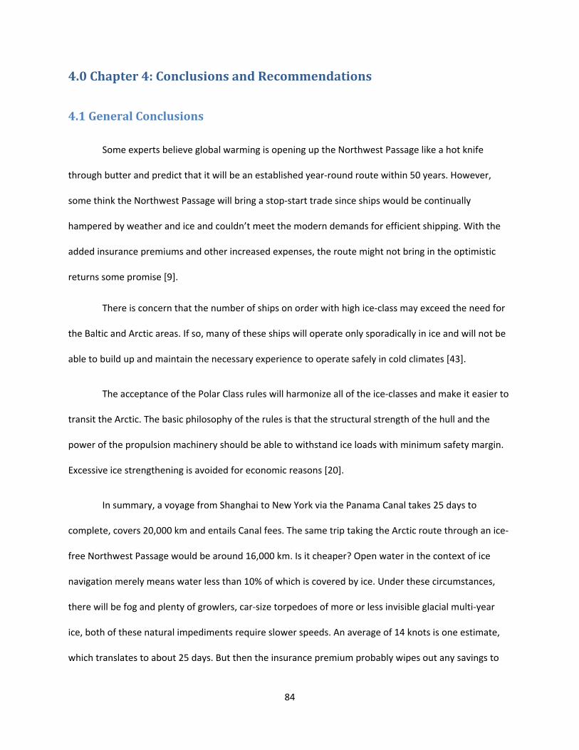
84
4.0 Chapter 4: Conclusions and Recommendations
4.1 General Conclusions
Some experts believe global warming is opening up the Northwest Passage like a hot knife
through butter and predict that it will be an established year‐round route within 50 years. However,
some think the Northwest Passage will bring a stop‐start trade since ships would be continually
hampered by weather and ice and couldn’t meet the modern demands for efficient shipping. With the
added insurance premiums and other increased expenses, the route might not bring in the optimistic
returns some promise [9].
There is concern that the number of ships on order with high ice‐class may exceed the need for
the Baltic and Arctic areas. If so, many of these ships will operate only sporadically in ice and will not be
able to build up and maintain the necessary experience to operate safely in cold climates [43].
The acceptance of the Polar Class rules will harmonize all of the ice‐classes and make it easier to
transit the Arctic. The basic philosophy of the rules is that the structural strength of the hull and the
power of the propulsion machinery should be able to withstand ice loads with minimum safety margin.
Excessive ice strengthening is avoided for economic reasons [20].
In summary, a voyage from Shanghai to New York via the Panama Canal takes 25 days to
complete, covers 20,000 km and entails Canal fees. The same trip taking the Arctic route through an ice‐
free Northwest Passage would be around 16,000 km. Is it cheaper? Open water in the context of ice
navigation merely means water less than 10% of which is covered by ice. Under these circumstances,
there will be fog and plenty of growlers, car‐size torpedoes of more or less invisible glacial multi‐year
ice, both of these natural impediments require slower speeds. An average of 14 knots is one estimate,
which translates to about 25 days. But then the insurance premium probably wipes out any savings to
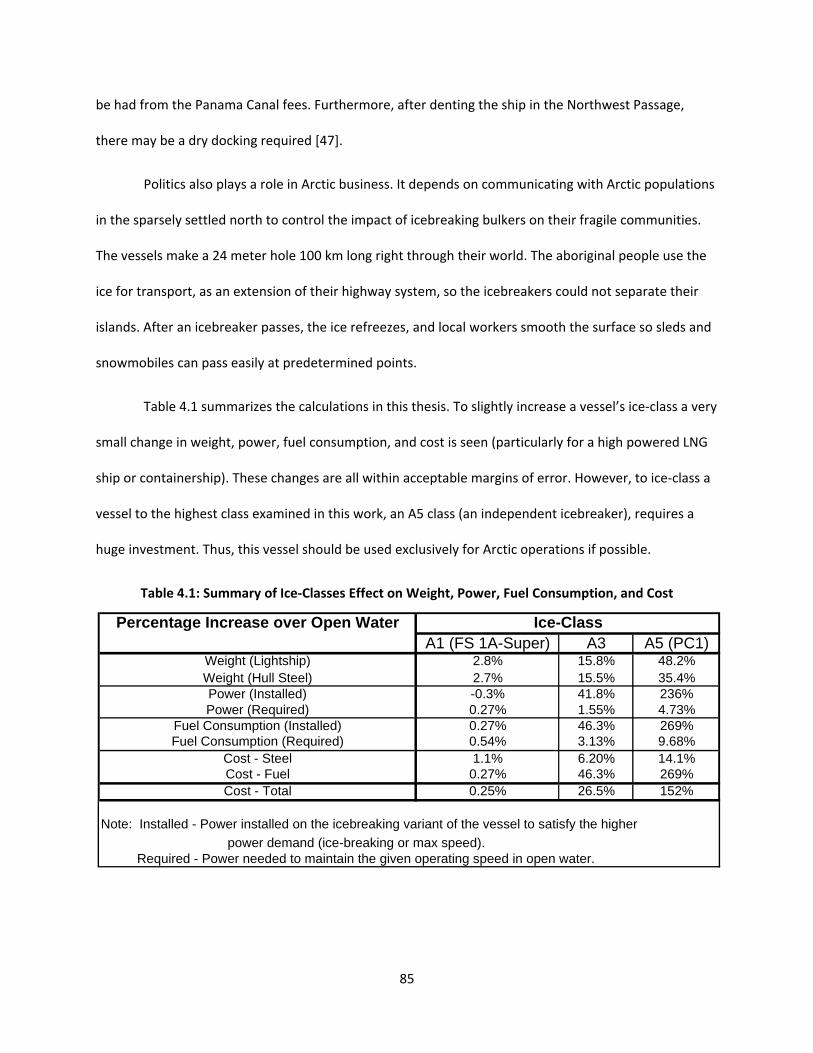
85
be had from the Panama Canal fees. Furthermore, after denting the ship in the Northwest Passage,
there may be a dry docking required [47].
Politics also plays a role in Arctic business. It depends on communicating with Arctic populations
in the sparsely settled north to control the impact of icebreaking bulkers on their fragile communities.
The vessels make a 24 meter hole 100 km long right through their world. The aboriginal people use the
ice for transport, as an extension of their highway system, so the icebreakers could not separate their
islands. After an icebreaker passes, the ice refreezes, and local workers smooth the surface so sleds and
snowmobiles can pass easily at predetermined points.
Table 4.1 summarizes the calculations in this thesis. To slightly increase a vessel’s ice‐class a very
small change in weight, power, fuel consumption, and cost is seen (particularly for a high powered LNG
ship or containership). These changes are all within acceptable margins of error. However, to ice‐class a
vessel to the highest class examined in this work, an A5 class (an independent icebreaker), requires a
huge investment. Thus, this vessel should be used exclusively for Arctic operations if possible.
Table 4.1: Summary of Ice‐Classes Effect on Weight, Power, Fuel Consumption, and Cost
Percentage Increase over Open WaterA1 (FS 1A-Super) A3 A5 (PC1)
Weight (Lightship) 2.8% 15.8% 48.2%Weight (Hull Steel) 2.7% 15.5% 35.4%Power (Installed) -0.3% 41.8% 236%Power (Required) 0.27% 1.55% 4.73%
Fuel Consumption (Installed) 0.27% 46.3% 269%Fuel Consumption (Required) 0.54% 3.13% 9.68%
Cost - Steel 1.1% 6.20% 14.1%Cost - Fuel 0.27% 46.3% 269%Cost - Total 0.25% 26.5% 152%
Note: Installed - Power installed on the icebreaking variant of the vessel to satisfy the higher
power demand (ice-breaking or max speed). Required - Power needed to maintain the given operating speed in open water.
Ice-Class

86
Presently, routing containerships over the Arctic is generally not considered by the industry to
be economically, politically, or environmentally feasible for continuous, reliable service. In the future,
when more experience is gained operating in the Arctic along with decreasing ice cover and the
harmonization of the ice‐class rules, ice‐classed containerships may emerge as a popular niche market.
One must remember the basic principles of ice navigation. The first principle of ice navigation is
to avoid ice. The second is when that's not possible, avoid the thicker ice. From the bridge, it all looks
white [47].

87
Appendix A: Summary of Weight Data Table A.1: Summary of Weight, Power, and Cost Data
Type Ice Class LBP B T D ∆ Hull Steel Lightship Power Cost % Increase Hull Steel/Lightship % Increase
(m) (m) (m) (m) (MT) (MT) (MT) (kW) $Million in Hull Steel in Lightship
Germanischer Lloyd
Suez‐Max Tanker Open Water 269 48 17 180,000 19,400
1A 20,361 22,500 5.0%
1A‐Super 20,802 27,500 7.2%
Aker Study
Norilskiy Nickel (650 TEU) LU‐7 160 23.1 9 14.2 13,000
750 TEU (Cap. 815 TEU) LU‐7 160 23.1 9 14.2 13,000
5000 TEU LU‐8 or LU‐9 269 34.6 13.5 21.3 100,000 32,000 36,000
NYK
4800 TEU D‐Class 283 32.2 13.5 21.8 51,390 $80‐$90
ABS
150,000 LNG Carrier Open Water 275 44.2 11.4 26 21,500 29,500 38,000 72.9%
1A 22,200 30,200 38,000 3.3% 73.5% 2.4%
PC7 22,735 30,735 38,000 5.7% 74.0% 4.2%
INSROP
Multi‐Purpose (532 TEU) 160 24.5 9 15.2 25,900 11,200 15,400
Herbert‐ABS
750 TEU Open Water 160 23.1 9 14.2 3,916 6,750 13,000 58.0%
5000 TEU Open Water 269 34.6 13.5 21.3 100,000 15,304 23,979 36,000 $91.3 63.8%
5000 TEU LU‐8 or LU‐9 269 34.6 13.5 21.3 100,000 23,325 32,000 36,000 $110.9 52.4% 72.9% 33.4%
ABS
138,000 m3 LNG Carrier
Open Water 266 42.6 11.3 26 107,000 22,600 28,800 29,050 78.5%
A1 107,000 23,061 29,261 29,050 2.0% 78.8% 1.6%
A3 107,000 26,105 33,357 41,845 15.5% 78.3% 15.8%
A5 107,000 30,592 42,692 102,370 35.4% 71.7% 48.2%
A5 ‐ Power of A3 107,000 30,592 37,844 35.4% 80.8% 31.4%
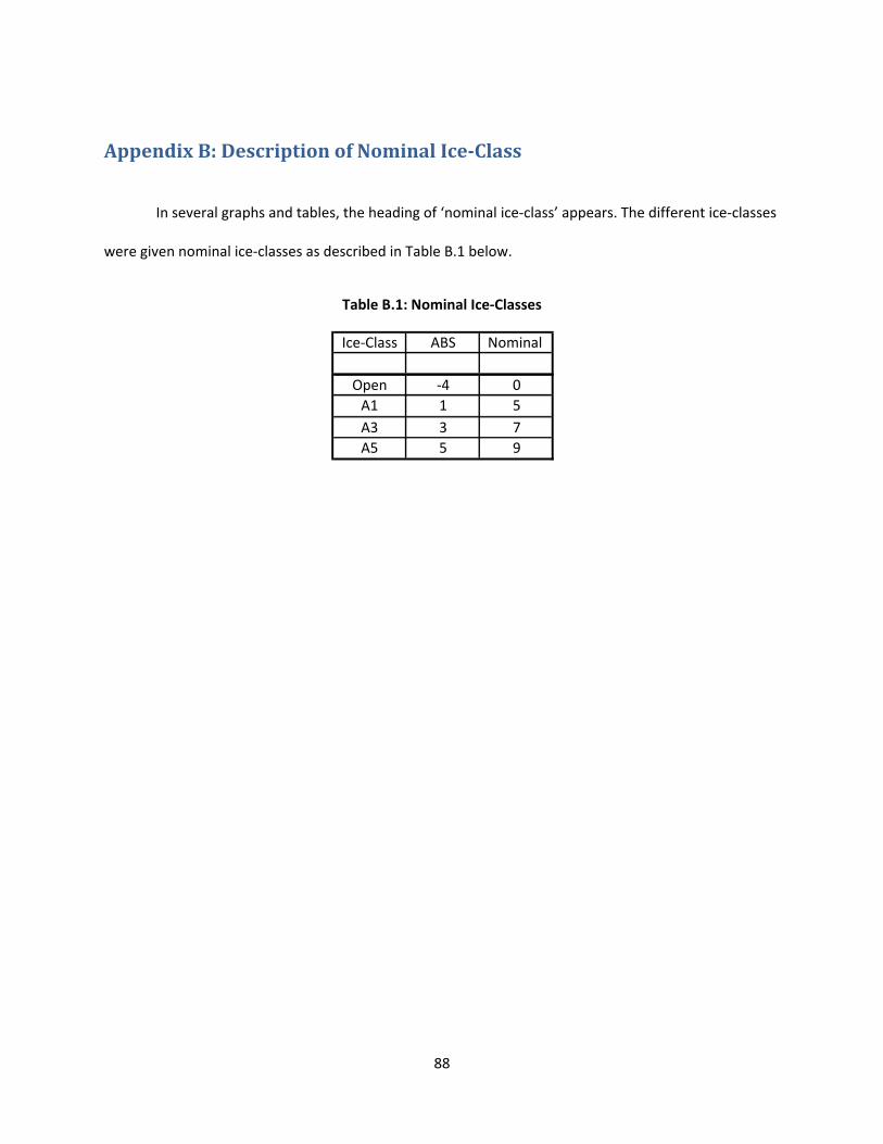
88
Appendix B: Description of Nominal IceClass
In several graphs and tables, the heading of ‘nominal ice‐class’ appears. The different ice‐classes
were given nominal ice‐classes as described in Table B.1 below.
Table B.1: Nominal Ice‐Classes
Ice‐Class ABS Nominal
Open ‐4 0
A1 1 5
A3 3 7
A5 5 9
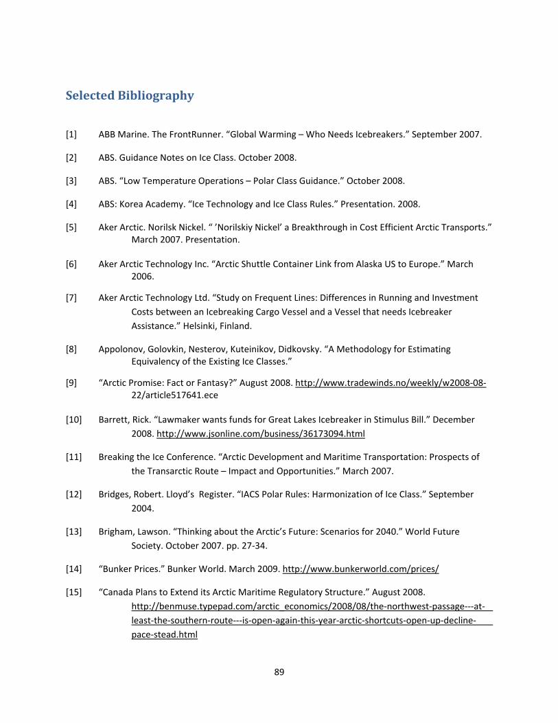
89
Selected Bibliography
[1] ABB Marine. The FrontRunner. “Global Warming – Who Needs Icebreakers.” September 2007.
[2] ABS. Guidance Notes on Ice Class. October 2008.
[3] ABS. “Low Temperature Operations – Polar Class Guidance.” October 2008.
[4] ABS: Korea Academy. “Ice Technology and Ice Class Rules.” Presentation. 2008.
[5] Aker Arctic. Norilsk Nickel. “ ’Norilskiy Nickel’ a Breakthrough in Cost Efficient Arctic Transports.” March 2007. Presentation. [6] Aker Arctic Technology Inc. “Arctic Shuttle Container Link from Alaska US to Europe.” March 2006.
[7] Aker Arctic Technology Ltd. “Study on Frequent Lines: Differences in Running and Investment
Costs between an Icebreaking Cargo Vessel and a Vessel that needs Icebreaker
Assistance.” Helsinki, Finland.
[8] Appolonov, Golovkin, Nesterov, Kuteinikov, Didkovsky. “A Methodology for Estimating Equivalency of the Existing Ice Classes.”
[9] “Arctic Promise: Fact or Fantasy?” August 2008. http://www.tradewinds.no/weekly/w2008‐08‐ 22/article517641.ece [10] Barrett, Rick. “Lawmaker wants funds for Great Lakes Icebreaker in Stimulus Bill.” December
2008. http://www.jsonline.com/business/36173094.html
[11] Breaking the Ice Conference. “Arctic Development and Maritime Transportation: Prospects of
the Transarctic Route – Impact and Opportunities.” March 2007.
[12] Bridges, Robert. Lloyd’s Register. “IACS Polar Rules: Harmonization of Ice Class.” September
2004.
[13] Brigham, Lawson. “Thinking about the Arctic’s Future: Scenarios for 2040.” World Future
Society. October 2007. pp. 27‐34.
[14] “Bunker Prices.” Bunker World. March 2009. http://www.bunkerworld.com/prices/
[15] “Canada Plans to Extend its Arctic Maritime Regulatory Structure.” August 2008.
http://benmuse.typepad.com/arctic_economics/2008/08/the‐northwest‐passage‐‐‐at‐
least‐the‐southern‐route‐‐‐is‐open‐again‐this‐year‐arctic‐shortcuts‐open‐up‐decline‐
pace‐stead.html
90
[16] “Canada to Double Reach of Arctic Shipping Regs.” August 2008. MarineLog.com.
http://www.marinelog.com/DOCS/NEWSMMVII/2008aug00282.html.
[17] Carlsen, Wilkman, Santos Pedro, Tikka, Noble. “The Arctic Challenge – A Panel Discussion on
Current and Future Arctic Marine Developments.” Presentation at SNAME Annual
Meeting. Houston. October 2008.
[18] DNV. “Arctic Operations and Technology.” Pamphlet.
[19] Dowd, Allan. “Canada to toughen requirements for ships in Arctic.” August 2008.
http://ca.reuters.com/article/domesticNews/idCAN2634309220080827?sp=true
[20] Duggal, BS and Kisen, Sanko. “Ice Strengthened Ships and Ice Rules.” 2006.
[21] “Engine Project Planning Guides.” Man B&W. 2008/2009. http://www.manbw.com/web/viewers/news/ArticleViewer.aspx?id=2572
[22] “Estimated US Flag Containership Costs: Foreign Trade (FY99 Price Levels) ITF Approved – 7
Years Old – Diesel Ship.” US Containerships. February 2009.
http://www.usace.army.mil/CECW/PlanningCOP/Documents/egms/egm99‐05j.pdf
[23] Femenia, Jose. “The Viability and Advantages of Trans‐Arctic Shipping Using Nuclear Powered
Ships.” A presentation for SNAME: New York. October 2008.
[24] Finnish and Swedish Maritime Administrations. “Guidelines for the Application of the Finnish‐
Swedish Ice Class Rules.” December 2005.
[25] Finnish Maritime Administration. “Amendments to the Finnish‐Swedish Ice Class Rules.”
December 2006.
[26] Finnish‐Swedish Ice Class Rules. “The Structural Design and Engine Output Required of Ships for
Navigation in Ice.”
[27] Garfield, Goeff. “Trailblazer Beluga.” September 2008. http://www.tradewinds.no/weekly/w2008‐09‐05/article518479.ece [28] Germanischer Lloyd. Business Development Manager Workshop Presentation. September 2005.
[29] Gillis, Chris. American Shipper. “Transshipments’s Last Frontier.” October 2008. pp. 73‐75.
[30] “Global Trade and Fuels Assessment – Future Trends and Effects of Requiring Clean Fuels in the Marine Sector.” United States Environmental Protection Agency. November 2008. http://www.epa.gov/otaq/regs/nonroad/marine/ci/420r08021.pdf [31] Gotman, Ada. “A History of Ship Resistance Evaluation.” The Journal of Ocean Technology.

91
[32] “Ice Classes and Requirements.” Swedish Maritime Administration. July 2008.
www.sjofartsverket.se/templates/SFVXPage_____5548.aspx
[33] “Icebreaker.” Wikipedia. February 2009. http://en.wikipedia.org/wiki/Icebreaker
[34] ICETECH 2008. “Proceedings of the 8th International Conference and Exhibition on Performance
of Ships and Structures in Ice.” July 2008.
[35] IMO: Marine Environment Protection Committee. “Prevention of Air Pollution from Ships.”
August 2008.
[36] Institute of the North. “Viability of Sakhalin ‐ Alaska – Alberta Commercial Aviation Links.” LPS Aviation Inc. June 2006. [37] Juva, Mikko and Riska, Kaj. “On the Power Requirement in the Finnish‐Swedish Ice Class Rules.”
Helsinki University of Technology: Ship Laboratory. September 2002.
[38] Kamesaki, Kazuhiko, Kishi, Susumu, and Yamauchi, Yutaka. “Simulation of NSR Shipping based
on Year‐Round and Seasonal Operation Scenarios.” International Northern Sea Route
Programme, 1999.
[39] Kubat, I., Timco, G.W., and Collins, A. “Examination of Shipping Regulations in the Canadian
Arctic – Time for Revisions.” IceTech Conference 2008.
[40] Lamb, Thomas. Ship Design and Construction, Vol. II. SNAME. 2004. Chapter 40: Ice‐Capable
Ships
[41] Le Coq, Christopher. “Arctic in the Balance.” July 2007. http://www.scitizen.com/stories/Climate‐Change/2007/07/Arctic‐in‐The‐Balance/
[42] Lloyd’s Register. “The Northern Sea Route – A Look into the Future”. Arctic Shipping 2008
Presentation. April 2008.
[43] “Managing Cold Climate Risks.” June 2005.
http://www.dnv.in/publications/classification_news/3_2005/Managingcold
climaterisks.asp?print=1
[44] Maritime Reporter and Engineering News. “Brodosplit Delivers Ice‐Class Product Tanker.” pg. 72.
[45] Maritime Reporter and Engineering News. “DAPPB: A New Concept in Arctic Sea
Transportation.” April 2008. pp. 42‐44.
[46] Mulrenan, Jim. “Claim Costs on Rise.” March 2009. http://www.tradewinds.no/weekly/w2009‐
03‐06/article531827.ece
[47] “Northwest Passage Talk is 'Greatly Exaggerated'.” August 2008. http://www.tradewinds.no/weekly/w2008‐08‐22/article517607.ece

92
[48] “Oil and Ice.” Germanischer Lloyd. Annual Report 2006. pp. 32‐33.
[49] Overgaard, Niels and Tustin, Rob. Lloyd’s Register. “Ice Class Tankers.” Presentation. April 2004.
[50] “Parametric Study of “Baby” Post‐Panamax Containerships.” August 2008. Herbert Engineering Corp. and the American Bureau of Shipping. [51] Park, H., Lee, Y., Ahn, S., Hwangbo, S., Jung, H., and Lee, J. “A Study on Bow Hull Form Design and Propulsion Type for Ice Breaking Vessel with theBalance of Open and Ice Performance.” IceTech Conference 2008. [52] Pechenyuk, Andrew. “ Computation of Perspective KRISO Containership Towing Tests with the
Help of the Complex of Hydrodynamical Analysis “Flow Vision”.” Digital Marine
Technology. February 2009. http://digitalmarine.net/builder/KCS_test.pdf
[53] Ragner, Claes Lykke. “Northern Sea Route Cargo Flows and Infrastructure – Present State and
Future Potential.” The Fridtjof Nansen Institute. 2000.
[54] “Requirements Concerning Polar Class.” IACS Req. 2007.
[55] Richardsen, Per Wiggo. “DNV Calls for New Approach to Safety in the Arctic.” September 2008.
http://www.dnv.com/press_area/press_releases/2008/dnvcallsfornewapproachto
safetyinthearctic.asp
[56] Richardsen, Per Wiggo. “Ice Load Monitoring Makes Arctic Navigation Safer.” March 2009. http://www.dnv.com/press_area/press_releases/2009/iceloadmonitoringmakes arcticnavigationsafer.asp [57] Solutions Magazine. “Sovcomflot’s Specialist Shuttles.” September 2008. pp. 24‐26.
[58] Solutions Magazine. “Experts Offer Arctic LNG Advice.” September 2008. pg. 28.
[59] “The 100+ Question.” Analysis Container. 2008.
[60] “The Northern Sea Route ‐ The Shortest Sea Route Linking East Asia and Europe.” The Ship and Ocean Foundation. 2001. [61] Timco, GW and Morin, I. “Canadian Ice Regime System Database.” Proceedings of the 8th International Offshore and Polar Engineering Conference. May 1998. [62] Wang, X., Sun, H., and Basu, R. "Structural Reliability Levels in Ice Class Rules.” ABS Technical
Papers 2007. pp. 29‐35.
[63] Ward, Paul. “Icebreakers and Ice‐Strengthened Ships.” 2001.
http://www.coolantarctica.com/Antarctica%20fact%20file/ships/icebreaker.htm

93
[64] Zhao, Rong. “A Nonlinear Method for Predicting Wave Resistance of Ships.” MARINTEK, Trondheim, Norway. http://www.iwwwfb.org/Abstracts/iwwwfb14/iwwwfb14_46.pdf