Engineered Wood Products - CMD Group & Installation Guide ... • Deeper depths allow for larger...
20
1 R O S E B U R G HYBRIDGREEN PANEL AVAILABLE Deep Depth RFPI® Joist - 18”, 20”, 22” & 24” Design & Installation Guide www.Roseburg.com Engineered Wood Products RFPI ® 700 RFPI ® 900 • Manufactured deeper to handle longer spans, wider spacing, higher loads • Lightweight for fast installation • Deeper depths allow for larger HVAC openings • Resists bowing, twisting and shrinking • Works with multiple spans • FSC certified available • Environmentally friendly • Product and performance warranty
Transcript of Engineered Wood Products - CMD Group & Installation Guide ... • Deeper depths allow for larger...

RoseburgFramingSystem® 1
R O S E B U R GHYBRIDGREEN
PANEL AVAILABLE
Deep Depth RFPI® Joist - 18”, 20”, 22” & 24”Design & Installation Guide
www.Roseburg.com
Engineered Wood Products
RFPI® 700RFPI® 900• Manufactureddeepertohandlelongerspans,widerspacing,higherloads
• Lightweightforfastinstallation
• DeeperdepthsallowforlargerHVACopenings
• Resistsbowing,twistingandshrinking
• Workswithmultiplespans
• FSCcertifiedavailable
• Environmentallyfriendly
• Productandperformancewarranty
2 RoseburgFramingSystem®
Architects,structuralengineersandbuilderscannowspecifyFSCcertifiedengineeredwoodproductsthatcancontributetoachievingadditionalLEED®creditsforyourproject.
RoseburghasbeencertifiedbyScientificCertificationSystems(SCS)toproduceForestStewardshipCouncil(FSC)CertifiedRFPI®JoistandRigidLam®LVLunderregistrationcodeSCS-COC-000300.WoodproductscertifiedbySCSarerecognizedascomingfromwell-managedforests,adheringtostrictenvironmentalandsocioeconomicstandardsinaccordancewiththeprinciplesandcriteriaoftheFSC.
FSC CeRtIFIed RFPI® JoISt & RIgIdLam® LVL are available From Roseburg
RFPI®-JoIsts SAFETYANDCONSTRUCTIONPRECAUTIONS 3 STORAgE&HANDLINggUIDELINES 3 DESIgNPROPERTIES 4 ALLOWAbLEFLOORSPANCHARTS 5 ALLOWAbLEFLOORUNIFORMLOADS 6 ALLOWAbLEROOFUNIFORMLOADS 6 WEbSTIFFENERREqUIREMENTS 7I-JoIstdetaIls FLOORFRAMINg&CONSTRUCTIONDETAILS 8-11
CANTILEVERDETAILS 11-12 ROOFFRAMINg&CONSTRUCTIONDETAILS13 WEbHOLESPECIFICATIONS 14 FIRE&SOUNDRATEDFLOORASSEMbLIES 15RIgIdlam®lVlHeadeRs&Beams PRODUCTLINE 16
DESIgNPROPERTIES 16 STORAgE,HANDLINg&INSTALLATION 16 HOLES&NAILINg 16 bEARINgDETAILS 17 FASTENINgRECOMMENDATIONSFOR MULTIPLEPLYMEMbERS 17-18
RIgIdRIm®RImBoaRdsPecIFIcatIons 19soFtwaReInFoRmatIon 20
Table Of Contents
ImPoRtant:All Roseburg Engineered Wood Products are intended and warrantied for use in dry-service conditions where the average moisture content of sawn lumber is less than 16%.
deSIgn SuPPoRtThevariouschartsandtablesinthisliteraturearebasedonaccepted,typicalloadingconditions,oncenterspacing,deflectioncriteriaand/orspans.This printed information allows the end user to identify and install properly sized RFP engineered wood products without the need for specific design or engineering calculations.Designsoftware;however,suchasRFP-Keybeam®andRFP-KeyPlan®fromKeymarkEnterprises,LLC,allowstheusertoinputprojectspecificinformationintothesoftwarewhichmaygivealessrestrictivesolutionthanthegenericinformationintheprintedliterature.RestassuredthatboththeliteratureandtheKeymarksoftwarearebasedontheappropriatedesignpropertieslistedinthecurrentcodereports.
Foradditionalassistancewithspecificproductdesignquestions,productavailability,andterritorysalesmanagerlocations,pleasevisitourwebsiteatwww.Roseburg.com,orcontactRoseburgForestProductsat1-800-347-7260,orattheaddresslistedonthebackcover.
Roseburg RFPI Joist and RigidLam LVL Leed Credit and Point InformationLEED CATEGORY/CREDIT INTENT REQUIREMENTS POSSIBLE POINTS
Indoor Environmental Quality EQ Credit 4.4: Low-Emitting Materials
Improves indoor air quality Wood products used shall contain no added urea-formaldehyde resins 1 point
Materials and Resources MR 5.1 Regional Materials: 10% Extracted, Processed & Manufactured Regionally
Increases the use of materials that are extracted and manufactured within the project region
A min. of 10% of the combined value of building materials or products must be extracted, harvested, or recovered, as well as manufactured within 500 miles of the project
1 point
Materials and Resources MR 5.2 Regional Materials: 20% Extracted, Processed & Manufactured Regionally
Increases the use of materials that are extracted and manufactured within the project region
A min. of 20% of the combined value of building materials or products must be extracted, harvested, or recovered, as well as manufactured within 500 miles of the project
1 point (in addition to MR credit 5.1)
Materials and Resources MR Credit 7.0: Certified WoodFSC - Forest Stewardship Council Encourage environmentally responsible
forest management
Use a minimum of 50% wood based materials and products, which are certified in accordance with the Forest Stewardship Council’s (FSC) Principles and Criteria, for wood building components
1 point
FSC SupplierSCS-COC-000300
The mark of responsible forestry© 1996 Forest Stewardship Council A.C.
RoseburgFramingSystem® 3
Deep
Dep
th R
FPI
®-Joist
Improperstorageorinstallation,failuretofollowapplicablebuildingcodes,failuretofollowspanratingsforRFPI®-JoistsorRigidLam®LVL,failuretouseallowableholesizesandlocations,orfailuretousewebstiffenerswhenrequiredcanresultinseriousaccidents.Followtheseinstallationguidelinescarefully.
These are general recommendations and in some cases additional precautions may be required.
Safety & Construction Precautions
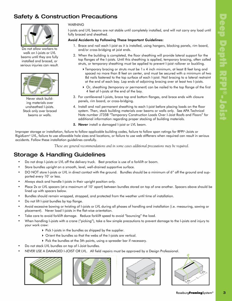
Storage & Handling Guidelines• DonotdropI-joistsorLVLoffthedeliverytruck. bestpracticeisuseofaforkliftorboom.
• Storebundlesuprightonasmooth,level,well-drainedsupportivesurface.
• DONOTstoreI-joistsorLVLindirectcontactwiththeground. bundlesshouldbeaminimumof6”offthegroundandsup-portedevery10’orless.
• AlwaysstackandhandleI-joistsintheiruprightpositiononly.
• Place2xorLVLspacers(atamaximumof10’apart)betweenbundlesstoredontopofoneanother.Spacersaboveshouldbelinedupwithspacersbelow.
• bundlesshouldremainwrapped,strapped,andprotectedfromtheweatheruntiltimeofinstallation.
• DonotliftI-joistbundlesbytopflange.
• AvoidexcessivebowingortwistingofI-joistsorLVLduringallphasesofhandlingandinstallation(i.e.measuring,sawingorplacement). NeverloadI-joistsintheflat-wiseorientation.
• Takecaretoavoidforkliftdamage. Reduceforkliftspeedtoavoid“bouncing”theload.
• WhenhandlingI-joistswithacrane(“picking”),takeafewsimpleprecautionstopreventdamagetotheI-joistsandinjurytoyourworkcrew:
4PickI-joistsinthebundlesasshippedbythesupplier.
4OrientthebundlessothatthewebsoftheI-joistsarevertical.
4Pickthebundlesatthe5thpoints,usingaspreaderbarifnecessary.
• DonotstackLVLbundlesontopofI-Joistbundles.
• NEVERUSEADAMAgEDI-JOISTORLVL. AllfieldrepairsmustbeapprovedbyaDesignProfessional.
LL 5
L 5
WARNINg
I-joistsandLVLbeamsarenotstableuntilcompletelyinstalled,andwillnotcarryanyloaduntilfullybracedandsheathed.
Avoid Accidents by Following These Important Guidelines:
1. braceandnaileachI-joistasitisinstalled,usinghangers,blockingpanels,rimboard,and/orcross-bridgingatjoistends.
2. Whenthebuildingiscompleted,thefloorsheathingwillprovidelateralsupportforthetopflangesoftheI-joists.Untilthissheathingisapplied,temporarybracing,oftencalledstruts,ortemporarysheathingmustbeappliedtopreventI-joistrolloverorbuckling.
4Temporarybracingorstrutsmustbe1x4inchminimum,atleast8feetlongandspacednomorethan8feetoncenter,andmustbesecuredwithaminimumoftwo8dnailsfastenedtothetopsurfaceofeachI-joist.Nailbracingtoalateralrestraintattheendofeachbay.LapendsofadjoiningbracingoveratleasttwoI-joists.
4Or,sheathing(temporaryorpermanent)canbenailedtothetopflangeofthefirst4feetofI-joistsattheendofthebay.
3. ForcantileveredI-joists,bracetopandbottomflanges,andbraceendswithclosurepanels,rimboard,orcross-bridging.
4. InstallandnailpermanentsheathingtoeachI-joistbeforeplacingloadsonthefloorsystem.Then,stackbuildingmaterialsoverbeamsorwallsonly.SeeAPATechnicalNotenumberJ735b“TemporaryConstructionLoadsOverI-JoistRoofsandFloors”foradditionalinformationregardingproperstackingofbuildingmaterials.
5. NeverinstalladamagedI-joistorLVLbeam.
Neverstackbuild-ingmaterialsoverunsheathedI-joists.Stackonlyoverbracedbeamsorwalls.
DonotallowworkerstowalkonI-joistsorLVLbeamsuntiltheyarefullyinstalledandbraced,orseriousinjuriescanresult.

4 RoseburgFramingSystem®
Dee
p D
epth
RFP
I®-J
oist
24̋22̋20̋18˝ 24̋22̋20̋18˝
DEsIGn PRoPERTIEs FoR RFPI-JoIsTs(1)
TAblE A: RFPI-JoIsT REAcTIon cAPAcITIEs WITh oR WIThouT WEb sTIFFEnERs (W.s.)(1) (2)
TAblE b: MAxIMuM ADJusTED REAcTIon cAPAcITy (1) (2)
RFPI®-Joist Design Properties I-JoIsT DIMEnsIons
(1)Thetabulatedvaluesaredesignvaluesfor100%durationofload.AllvaluesexceptforEIandKarepermittedtobeadjustedforotherloaddurationsaspermittedbycode.DesignvalueslistedareapplicableforAllowableStressDesign(ASD).
(2)bendingstiffness(EI)oftheI-joist.
(3)Momentcapacity(M)ofasingleI-joist.momentcapacityoftheI-Joistshallnotbeincreasedbyanyrepetitivememberusefactor.(4)Shearcapacity(V)oftheI-joist.
(5)VerticalLoadCapacitywhencontinuouslysupported.
(6)Coefficientofsheardeflection(K),usedtocalculatedeflectionsforI-joistapplication.Equations1and2belowareprovidedforuniformloadandcenterpointloadconditionsforsimplespans.
UniformLoad:
[1] d= 5v,4 +v,2 ______ ____ 384EI K
d= P,3 +2P, _____ ___
48EI K
Center-PointLoad:
[2]
where:d=calculateddeflection(in.)v=uniformload(lb/in.),=designspan(in.)P=concentratedload(lb)
EI=bendingstiffnessoftheI-joist(lb-in2)K=coefficientofsheardeflection(lb)
RoseburgDesignation
El(2)
x106 lb-in.2M(3)
lb-ftV(4)
lbVlc(5)
lb/ftK(6)
x106 lbWeight
lb/ft
18"RFPI700 1245 10,450 2,575 2,200 11.34 3.85
20”RFPI700 1579 11,600 2,740 2,200 12.60 4.10
22”RFPI700 1955 12,740 2,935 1,800 13.86 4.36
24”RFPI700 2375 13,870 3,060 1,750 15.12 4.61
18"RFPI900 1849 16,080 2,885 2,200 11.34 4.80
20”RFPI900 2337 17,855 2,945 2,200 12.60 5.21
22”RFPI900 2886 19,615 3,010 1,800 13.86 5.47
24”RFPI900 3496 21,355 3,060 1,750 15.12 5.67
RoseburgDesignation
End Reaction (lbs) Intermediate Reaction (lbs)
1-3/4” bearing 3-1/2” bearing 3-1/2” bearing 5-1/4” bearing
NoW.S. WithW.S. NoW.S. WithW.S. NoW.S. WithW.S. NoW.S. WithW.S.
18"RFPI700 1,125 2,200 1,650 2,575 2,745 4,050 3,025 4,475
20”RFPI700 1,090 2,300 1,585 2,740 2,745 4,050 3,025 4,475
22”RFPI700 - 2,400 - 2,935 - 4,150 - 4,605
24”RFPI700 - 2,500 - 3,060 - 4,150 - 4,605
18"RFPI900 1,475 2,570 1,765 2,885 3,000 5,110 3,475 5,710
20”RFPI900 1,350 2,665 1,700 2,945 3,000 5,110 3,475 5,710
22”RFPI900 - 2,755 - 3,010 - 5,405 - 6,020
24”RFPI900 - 2,850 - 3,060 - 5,405 - 6,020
RoseburgDesignation
End Reaction (lbs) Intermediate Reaction (lbs)
1-3/4” bearing 3-1/2” bearing 3-1/2” bearing 5-1/4” bearing
NoW.S. WithW.S. NoW.S. WithW.S. NoW.S. WithW.S. NoW.S. WithW.S.
AllRFPI700 2,285 4,575 5,065 7,355
AllRFPI900 3,535 7,070 7,825 11,365
RFPI® 700 RFPI® 900
2-5/16” wide x 1-1/2” LVL Flange7/16” OSB Web
3-1/2” wide x 1-1/2” LVL Flange7/16” OSB Web
TableANotes:
(1)Thetabulateddesignval-uesinTableAarefor100%durationofload.Interpolationbetweentabulatedvaluesispermitted.AllvaluesinTableAshallbepermittedtobeadjustedforotherloaddura-tionsprovidedthatthefinalreactiondesignvalue(whetheradjustedornot)isnotgreaterthanthevaluetabulated(orinterpolated)inTablebbelow.
(2)RefertoWeb Stiffener Requirementsonpage7forwebstiffenersizeandnailrequirements.
TablebNotes:
(1)Maximumallowablereac-tioncapacitybasedonflangeFcperp.ThefinalreactionvaluefromTableAshallnotexceedthetabulated(orinter-polated)valuefromTableb.
(2)ThevaluesinTablebarefor100%durationofloadandshall notbeincreasedforshorterdurationsofload.

RoseburgFramingSystem® 5
Deep
Dep
th R
FPI
®-JoistAllowable Floor Clear Spans For RFPI®-Joists 40 PsF lIVE loAD AnD 25 PsF DEAD loAD
DEFlEcTIon lIMITs - lIVE loAD = l/480 ToTAl loAD = l/240
50 PsF lIVE loAD, 15 PARTITIon, 25 PsF DEAD loAD AnD 2000 lb concEnTRATED loAD
DEFlEcTIon lIMITs - lIVE loAD = l/600 ToTAl loAD = l/240
100 PsF lIVE loAD, 25 PsF DEAD loAD AnD 2000 lb concEnTRATED loAD
DEFlEcTIon lIMITs - lIVE loAD = l/600 ToTAl loAD = l/240
125 PsF lIVE loAD, 25 PsF DEAD loAD AnD 2000 lb concEnTRATED loAD
DEFlEcTIon lIMITs - lIVE loAD = l/360 ToTAl loAD = l/240
Joistdepth Joistseries
simplespan multiplespan
12”o.c. 16”o.c. 19.2”o.c. 24”o.c. 12”o.c. 16”o.c. 19.2”o.c. 24”o.c.18” RFPI®700 33’-0” 30'-1" 28'-2" 25'-3" 35'-8" 30'-10" 28'-2" 24'-8"20” RFPI®700 35'-9" 32'-7" 29'-9" 26'-7" 37'-7" 32'-6" 29'-8" 24'-8"22” RFPI®700 38'-4" 34'-2" 31'-2" 27'-10" 39'-5" 34'-1" 31'-1" 25'-4"24” RFPI®700 40'-11" 35'-8" 32'-6" 29'-1" 41'-1" 35'-7" 31'-8" 25’-4”18” RFPI®900 37'-2" 33'-10" 31'-11" 29'-8" 40'-7" 36'-11" 34'-9" 31'-3"20” RFPI®900 40'-3" 36'-7" 34'-6" 32'-1" 43'-11" 39'-11" 36'-10" 31’-3”22” RFPI®900 43'-2" 39'-3" 37'-0" 34'-5" 47'-1" 42'-4" 38'-8" 33'-1"24” RFPI®900 46'-0" 41'-11" 39'-6" 36'-1" 50'-3" 44'-2" 40'-4" 33’-1”
Joistdepth Joistseries
simplespan multiplespan
12”o.c. 16”o.c. 19.2”o.c. 24”o.c. 12”o.c. 16”o.c. 19.2”o.c. 24”o.c.18” RFPI®700 25'-9" 23'-5" 22'-0" 20'-6" 28'-0" 25'-5" 22'-3" 17'-9"20” RFPI®700 27'-10" 25'-4" 23'-10" 22'-2" 30'-4" 26'-9" 22'-3" 17'-9"22” RFPI®700 29'-11" 27'-3" 25'-7" 23'-8" 32'-7" 27'-5" 22'-10" 18'-3"24” RFPI®700 31'-11" 29'-1" 27'-4" 24'-8" 34'-9" 27'-5" 22'-10" 18'-3"18” RFPI®900 28'-11" 26'-3" 24'-8" 22'-11" 31'-6" 28'-7" 26'-10" 22'-6"20” RFPI®900 31'-4" 28'-5" 26'-8" 24'-9" 34'-1" 30'-11" 28'-2" 22'-6"22” RFPI®900 33'-7" 30'-6" 28'-8" 26'-7" 36'-7" 33'-2" 29'-10" 23'-10"24” RFPI®900 35'-10" 32'-7" 30'-7" 28'-4" 39'-1" 35'-5" 29'-10" 23'-10"
Joistdepth Joistseries
simplespan multiplespan
12”o.c. 16”o.c. 19.2”o.c. 24”o.c. 12”o.c. 16”o.c. 19.2”o.c. 24”o.c.18” RFPI®700 22'-0" 20'-0" 18'-9" 17'-5" 23'-11" 19'-3" 16'-0" 12'-9"20” RFPI®700 23'-10" 21'-8" 20'-4" 18'-2" 25'-8" 19'-3" 16'-0" 12'-9"22” RFPI®700 25'-8" 23'-3" 21'-10" 18'-2" 26'-4" 19'-8" 16'-5" 13'-1"24” RFPI®700 27'-4" 24'-10" 22'-8" 18'-2" 26'-4" 19'-8" 16'-5" 13'-1"18” RFPI®900 24'-9" 22'-5" 21'-0" 19'-5" 26'-11" 24'-3" 20'-3" 16'-2"20” RFPI®900 26'-10" 24'-3" 22'-9" 21'-0" 29'-1" 24'-4" 20'-3" 16'-2"22” RFPI®900 28'-9" 26'-0" 24'-5" 21'-11" 31'-3" 25'-9" 21'-5" 17'-1"24” RFPI®900 30'-8" 27'-9" 26'-1" 22'-8" 33'-5" 25'-9" 21'-5" 17'-1"
Joistdepth Joistseries
simplespan multiplespan
12”o.c. 16”o.c. 19.2”o.c. 24”o.c. 12”o.c. 16”o.c. 19.2”o.c. 24”o.c.18” RFPI®700 23'-6" 20'-4" 18'-2" 14'-6" 21'-5" 16'-0" 13'-3" 10'-7"20” RFPI®700 24'-9" 21'-5" 18'-11" 15'-1" 21'-5" 16'-0" 13'-3" 10'-7"22” RFPI®700 25'-11" 22'-5" 18'-11" 15'-1" 21'-11" 16'-5" 13'-7" 10'-10"24” RFPI®700 27'-1" 22'-8" 18'-11" 15'-1" 21'-11" 16'-5" 13'-7" 10'-10"18” RFPI®900 27'-6" 24'-11" 21'-3" 17'-0" 27'-0" 20'-3" 16'-10" 13'-5"20” RFPI®900 29'-9" 26'-6" 22'-1" 17'-7" 27'-0" 20'-3" 16'-10" 13'-5"22” RFPI®900 31'-11" 27'-5" 22'-10" 18'-3" 28'-7" 21'-5" 17'-10" 14'-2"24” RFPI®900 33'-7" 28'-4" 23'-7" 18'-10" 28'-7" 21'-5" 17'-10" 14'-2"
notes:•Web stiffeners ARE required for spans shown. seeWebStiffenerRequirements on page 7.•Clearspanisthecleardistancebetweenthefaceofsupports.•Spansarebasedonuniformloadsandconcentratedloadsasshownabove.UseRFP-Keybeam®sizingsoftwareforotherloading.
•Aminimumof1C\v”isrequiredforendbearing,3Z\x”forintermediatebearing.•MultipleSpanlengthsshownrequiretheinstallationofadequatebottomflangelateralbracing.•Spansarebasedoncompositeactionwithglued-nailedsheathingmeetingthefollowingAPArequirements:
AdhesivesshallmeetAPASpecificationAFg-01orASTMD3498.
Min.Thickness SpanRating FloorJoistSpacingRatedSheathingRatedSheathing
19/32”23/32”
(40/20)(48/24)
19.2”orless24”orless
RatedSturd-IFloorRatedSturd-IFloor
19/32”23/32”
20”o.c.24”o.c.
19.2”orless24”orless
lAyouT GuIDE FoR 19.2” o.c. sPAcInG
1 19-3/16” 6 115-3/16” 11 211-3/16”2 38-3/8” 7 134-3/8” 12 230-3/8”3 57-5/8” 8 153-5/8” 13 249-5/8”4 76-13/16” 9 172-13/16” 14 268-13/16”5 96”(8’) 10 192”(16’) 15 288”(24’)
6 RoseburgFramingSystem®
Dee
p D
epth
RFP
I®-J
oist
Jois
tcle
ar
span
(ft) RFPI700
(2-5/16”widex1-1/2”flanges)RFPI900
(3-1/2”widex1-1/2”flanges)18” 20” 22” 24” 18” 20” 22” 24”
Live Total Live Total Live Total Live Total Live Total Live Total Live Total Live Total10 - 313 - 313 - 321 - 320 - 395 - 395 - 418 - 41712 - 261 - 261 - 267 - 267 - 330 - 329 - 348 - 34814 - 224 - 224 - 229 - 229 - 283 - 282 - 299 - 29816 - 196 - 196 - 200 - 200 - 247 - 247 - 261 - 26118 157 174 - 174 - 178 - 178 218 220 - 219 - 232 - 23220 118 156 147 156 - 160 - 160 166 197 - 197 - 208 - 20822 91 142 114 142 139 145 - 145 129 179 159 179 - 189 - 18924 71 130 89 130 109 133 131 132 102 164 126 164 153 173 - 17326 57 118 72 119 88 122 105 122 82 151 102 151 123 159 147 15928 46 101 58 111 71 113 86 113 66 140 83 140 101 148 121 14830 38 88 48 98 59 106 71 105 55 130 68 130 83 138 100 13732 32 75 40 85 49 94 59 98 46 109 57 122 70 129 84 12934 26 62 33 75 41 83 49 90 38 91 48 114 59 121 71 12136 22 52 28 67 35 73 42 80 33 77 41 97 50 114 60 11438 - - 24 56 30 65 36 71 28 65 35 82 43 102 52 10740 - - - - 26 59 31 64 24 55 30 70 37 87 45 10042 - - - - 22 51 27 58 - - 26 61 32 75 39 9044 - - - - - - 24 52 - - 23 52 28 65 34 7946 - - - - - - - - - - - - 25 57 30 6948 - - - - - - - - - - - - - - 26 6050 - - - - - - - - - - - - - - 23 5352 - - - - - - - - - - - - - - - -54 - - - - - - - - - - - - - - - -56 - - - - - - - - - - - - - - - -58 - - - - - - - - - - - - - - - -
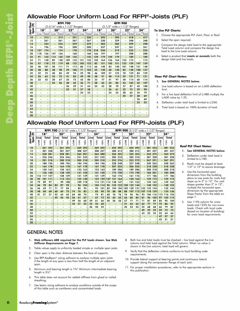
Allowable Floor Uniform Load For RFPI®-Joists (PLF)
Allowable Roof Uniform Load For RFPI-Joists (PLF)
Jois
tcle
ar
span
(ft)
RFPI700(2-5/16”widex1-1/2”flanges) RFPI900(3-1/2”widex1-1/2”flanges)18” 20” 22” 24” 18” 20” 22” 24”
live Total live Total live Total live Total live Total live Total live Total live Total
l/240
115%
125%
l/240
115%
125%
l/240
115%
125%
l/240
115%
125%
l/240
115%
125%
l/240
115%
125%
l/240
115%
125%
l/240
115%
125%
10 - 361 392 - 361 392 - 369 392 - 369 392 - 455 495 - 455 495 - 481 523 - 481 52312 - 301 328 - 301 327 - 308 327 - 308 327 - 380 413 - 380 413 - 401 437 - 401 43714 - 258 281 - 258 281 - 264 281 - 264 280 - 326 355 - 325 354 - 344 375 - 344 37416 - 226 246 - 226 246 - 231 245 - 231 245 - 285 310 - 285 310 - 301 328 - 301 32818 - 201 218 - 200 218 - 205 218 - 205 218 - 253 276 - 253 275 - 267 291 - 267 29120 - 180 196 - 180 196 - 184 196 - 184 196 - 228 248 - 227 248 - 240 262 - 240 26222 - 164 178 - 164 178 - 167 178 - 167 178 - 207 225 - 206 225 - 218 238 - 218 23824 - 150 163 - 150 163 - 153 163 - 153 163 - 189 206 - 189 206 - 200 218 - 200 21826 - 136 148 - 138 150 - 141 150 - 141 150 - 175 190 - 174 190 - 184 201 - 184 20028 116 117 127 - 128 139 - 131 139 - 131 139 - 162 176 - 161 176 - 171 186 - 171 18630 95 101 111 - 113 123 - 122 130 - 122 129 137 151 164 - 150 164 - 159 173 - 159 17332 79 89 97 - 99 108 - 109 118 - 114 121 114 138 147 - 141 153 - 149 162 - 149 16234 66 78 84 83 87 95 - 96 104 - 104 114 96 122 123 120 132 144 - 140 152 - 140 15236 56 69 71 71 77 84 - 85 93 - 93 101 82 104 104 102 120 131 125 132 144 - 132 14438 48 60 60 60 69 75 74 76 83 - 83 90 70 88 88 88 107 112 107 118 129 - 124 13640 41 51 51 52 62 65 64 68 74 - 74 81 60 76 76 76 96 96 93 106 116 112 116 12642 - - - 45 56 56 56 61 67 - 67 73 52 65 65 66 82 82 81 96 102 97 105 11444 - - - - - - 49 56 60 59 61 66 46 56 56 57 71 71 71 87 89 85 95 10446 - - - - - - 43 51 53 52 55 60 - - - 51 62 62 62 77 77 75 86 9448 - - - - - - - - - 46 50 55 - - - 45 54 54 55 68 68 66 79 8250 - - - - - - - - - - - - - - - - - - 49 59 59 59 72 7352 - - - - - - - - - - - - - - - - - - 43 52 52 52 64 6454 - - - - - - - - - - - - - - - - - - - - - 47 57 5756 - - - - - - - - - - - - - - - - - - - - - 42 51 5158 - - - - - - - - - - - - - - - - - - - - - - - -
FloorPlFchartnotes:
1. see GEnERAl noTEs below.
2. LiveloadcolumnisbasedonanL/600deflectionlimit.
3. ForaliveloaddeflectionlimitofL/480multiplytheL/600valueby1.25.
4. DeflectionundertotalloadislimitedtoL/240.
5. Totalloadisbasedon100%durationofload.
RoofPlFchartnotes:1. see GEnERAl noTEs below.
2. DeflectionundertotalloadislimitedtoL/180.
3. Roofsmustbeslopedatleast1/4”in12”toassuredrainage.
4. Usethehorizontalspandimensionfromthebuildingplanstosizejoistsforroofsthatslopeupto2”in12”.Forroofslopesgreaterthan2”in12”,multiplythehorizontalspandimensionbytheappropriateSlopeFactorfromthetableonpage7.
5. Use115%columnforsnowloadsand125%fornon-snowloads.Checkwithlocalcode(basedonlocationofbuilding)forsnowloadrequirements.
1. Web stiffeners ARE required for the PlF loads shown. seeWebStiffenerRequirements on Page 7.
2. Tablevaluesapplytouniformlyloadedsimpleormultiplespanjoists.
3. Clearspanisthecleardistancebetweenthefaceofsupports.
4. UseRFP-Keybeam®sizingsoftwaretoanalyzemultiplespanjoistsifthelengthofanyspanislessthanhalfthelengthofanadjacentspan.
5. Minimumendbearinglengthis1C\v”.Minimumintermediatebearinglengthis3Z\x”.
6. Thistabledoesnotaccountforaddedstiffnessfromgluedornailedsheathing.
7. Usebeamsizingsoftwaretoanalyzeconditionsoutsideofthescopeofthistablesuchascantileversandconcentratedloads.
8. bothliveandtotalloadsmustbechecked–liveloadagainsttheLivecolumnandtotalloadagainsttheTotalcolumn.WhennovalueisshownintheLivecolumn,totalloadwillgovern.
9. Verifythatthedeflectioncriteriaconformstolocalbuildingcoderequirements.
10. Providelateralsupportatbearingpointsandcontinuouslateralsupportalongthecompressionflangeofeachjoist.
11. Forproperinstallationprocedures,refertotheappropriatesectionsinthispublication.
toUsePlFcharts:1. ChoosetheappropriatePLFchart,FloororRoof
2. Selectthespanrequired.
3. ComparethedesigntotalloadtotheappropriateTotalLoadcolumnandcomparethedesignliveloadtotheLiveLoadcolumn.
4. Selectaproductthatmeets or exceedsboththedesigntotalandliveloads.
general notes

RoseburgFramingSystem® 7
Deep
Dep
th R
FPI
®-JoistWeb Stiffener RequirementsWeb stiffeners are required for all 22” and 24” deep RFPI joist applications. Depending on the loads and spans, web stiffeners may or may not be required for 18” and 20” deep RFPI joists.Awebstiffenerisablockofplywood,OSb,or2xthatisaddedtostiffentheI-joist’sweb,increasethebearingsurfacebetweenthewebandtheflange,andprovideadditionalsupportforahangerorotherconnector.The proper installation of web stiffeners is very important, particularly for deeper depth I-joists which are capable of carrying large loads and developing high reactions.Whenusedatendorintermediatebearings,webstiffenersmustbeinstalledonbothsidesofthewebandtightagainstthebottomflangeoftheI-joist,butwithaminimum1/8”gapbetweenthetopofthestiffenerandthebottomofthetopflange.Web stiffeners must be made of utility grade sPF (south) or better for lumber and/or sheathing grade or better for wood structural panels.
Webstiffenersarealsorequiredforthefollowing:• WhensidesofthehangersdonotlaterallybracethetopflangeoftheI-joist.
• WhenI-joistsaredesignedtosupportconcentratedloadsgreaterthan1000lbsappliedtotheI-joist’stopflangebetweensupports.Intheseapplicationsonly,thegapbetweenthewebstiffenerandtheflangeshallbeatthebottomflange.(SeeFigurebbelow.)
FIgUREb
RFPI-JoIsT WEb sTIFFEnER REQuIREMEnTs
See webstiffenernailing schedulebelow
RFPI®-Joistseries Joistdepth minimumwebstiffenersize nailRequirement
RFPI700 18”&20” 7/8”x3-1/2” 8-8dbox(0.113”diax2-1/2”)
RFPI700 22”&24” 7/8”x3-1/2” 10-8dbox(0.113”diax2-1/2”)
RFPI900 18”&20” 1-1/2”x3-1/2” 8-16dbox(0.135”diax3-1/2”)
RFPI900 22”&24” 1-1/2”x3-1/2” 10-16dbox(0.135”diax3-1/2”)
TAbLEb
WEb sTIFFEnER nAIlInG schEDulE
Webstiffenersmaybecutinthefieldasrequiredfortheapplication.
AlonG-ThE-sloPE sPAns & cuTTInG lEnGThs FoR sloPED RooFs
12X
RFPI-JoistDepth
DepthCorrection
SlopedLength
CutLength[feet]=(PlanDimensionxFactor)+DepthCorrection
PlanDimension(feet)
Slope Length Conversion Chart
slopeslope Factor
Joist Depth (inches)
18 20 22 24
Depth correction (feet)
1in12 1.00 0.13 0.14 0.15 0.17
2in12 1.01 0.25 0.28 0.31 0.33
2.5in12 1.02 0.31 0.35 0.38 0.42
3in12 1.03 0.38 0.42 0.46 0.50
3.5in12 1.04 0.44 0.49 0.53 0.58
4in12 1.05 0.50 0.56 0.61 0.67
4.5in12 1.07 0.56 0.63 0.69 0.75
5in12 1.08 0.63 0.69 0.76 0.83
6in12 1.12 0.75 0.83 0.92 1.00
7in12 1.16 0.88 0.97 1.07 1.17
8in12 1.20 1.00 1.11 1.22 1.33
9in12 1.25 1.13 1.25 1.38 1.50
10in12 1.30 1.25 1.39 1.53 1.67
11in12 1.36 1.38 1.53 1.68 1.83
12in12 1.41 1.50 1.67 1.83 2.00

8 RoseburgFramingSystem®
Dee
p D
epth
RFP
I®-J
oist
4 5
2 3
7
1 97 8 10
InsTAllATIon noTEs 1. Exceptforcuttingtolength,topandbottomflangesofRFPI-Joists
shallnotbecut,drilledornotched.2. Webstiffenersarerequiredforall22”and24”deepRFPIjoist
applications.Dependingontheloadsandspans,webstiffenersmayormaynotberequiredfor18”and20”deepRFPIjoists.
3. Installjoisthangersperhangermanufacturersrecommendations.4. Concentratedloadsgreaterthanthosethatcannormallybe
expectedinresidentialconstructionshouldonlybeappliedtothetopsurfaceofthetopflange.Normalconcentratedloadsincludetracklightingfixtures,audioequipmentandsecuritycameras.NeversuspendunusualorheavyloadsfromtheI-joist’sbottomflange.Wheneverpossible,suspendallconcentratedloadsfromthetopoftheI-joist.Or,attachtheloadtoblockingthathasbeensecurelyfastenedtotheI-joistweb.
5. Anyfastening,resistancetoupliftorapplicationsnotspecificallydetailedaresubjecttolocalapproval.
6. I-Joistendbearinglengthmustbeatleast1¾”.Intermediatebearingsofmultiplespanjoistsmustbeatleast3½”.
7. Engineeredlumbermustnotremainindirectcontactwithconcreteormasonryconstructionandmustbeusedindry-service conditions only.
8. RFPI-Joistsmustberestrainedagainstrotationattheendsofjoistsbyuseofrimboard,rimjoists,blockingpanels,orcross-bracing.Tolaterallysupportcantileveredjoists,blockingpanelsmustalsobeinstalledoversupportsnearestthecantilever.
9. Additionally,rimboard,rimjoists,blockingpanels,orsquashblocksmustbeprovidedunderallexteriorwallsandinteriorloadbearingwallstotransferloadsfromabovetothewallorfoundationbelow.
10. PlywoodorOSbsubfloornailedtothetopflangeofanRFPI-Joistisadequatetoprovidelateralsupport.
11. InstallI-joistssothattopandbottomflangesarestraightandremainwithin½inchoftruealignment.
12. Roseburgdoesnotrequiremid-spanblockingorbridginginRFPIfloororroofapplications
13. IfnailsmustbeinstalledintothesidesofLVLflanges,spacingshallnotbecloserthan3incheso.c.for8dcommonnails,and4incheso.c.for10dcommonnails.
14. RFPI-Joistsareproducedwithoutcambersoeitherflangecanbethetoporbottomflange;however,orientingthefloorI-joistssothepre-scoredknockoutsareonthebottommayeaseinstallationofelectricalwiringorresidentialsprinklersystems.
15. Whennailingsheathingtotopflange,closestspacingshouldbeasfollows:
TyPIcAl RFPI ®-JoIsT FlooR FRAMInG AnD consTRucTIon DETAIlsAllnailsshowninthedetailsbelowareassumedtobecommonnailsunlessotherwisenoted.10dboxnailsmaybesubstitutedfor8dcommonshownindetails.Individualcomponentsnotshowntoscaleforclarity.
Floor Framing & Construction Details
Flangewidth
sheathingnailspacingRequirements
2-5/16” 3-1/2”
min max min max
8dboxorcommon,10dor12dbox 2” 24” 2” 24”
nAIlInG noTEs:
1. Ifmorethanonerowofnailsisrequired,rowsmustbeoffsetbyatleastZ\x”andstaggered.
2. 14gaugestaplesmaybesubstitutedfor8dnailsifstaplespenetratethejoistatleast1”.
3. DonotusenailslargerthanthoseshownabovewhenattachingsheathingtoflangesofRFPI-Joists.
4. Spacenailsinstalledtotheflange’stopfaceinaccordancewiththeapplicablebuildingcoderequirementsorapprovedbuildingplans.
5. Ifsheathingistobeattachedwithscrews,thescrewsizeshouldbeequaltooronlyslightlylargerthantherecommendednailsize.Spacethescrewsthesameastherequirednailspacing.TheunthreadedshankofthescrewshouldextendbeyondthethicknessofthepaneltoassurethatthepanelispulledsecurelyagainsttheI-joistflange.Usescrewsintendedforstructuralassemblyofwoodstructures.ItisrecommendedtousescrewsfromamanufacturerthatcanprovideanICC-ESReportwithapprovedapplicationspecificationsanddesignvalues.Drywallscrewscanbebrittleandshouldnotbeused.
WARnInG: InstalltemporarybracingperSafety and Instruction Precautionsonpage3.InstallWebStiffenerseach
sideofI-joistasrequired.SeeInstallationNote2below.

RoseburgFramingSystem® 9
Deep
Dep
th R
FPI
®-JoistblocKInG PAnEls1
RFPI® blocking panel-or-RigidRimRimboard
Attach blocking panel(orRimboard)totopplatewith8dnails@6”o.c.(whenusedforlateralsheartransfer,nailtobearingplatewithsamenailingasrequiredfordecking)
AttachI-joisttotopplateperDetail2
RigidRim® RIMboARD2RigidRim® Rimboard(seepage19fordesignproperties)
One8dnailattopandbottomflange
Attach RigidRim® Rimboardtotopplateusing8dboxtoenails@6”o.c.(whenusedforlateralsheartransfer,nailtobearingplatewithsamenailingasrequiredfordecking)
one 8d nail each sideoftheRFPI-Joistatbearing.To avoid splitting flange,startnailsatleast1Z\x”fromendofI-joist.Nailsmaybedrivenatanangletoavoidsplittingofbearingplate.
RFPI® RIM JoIsT3Attach rim joisttofloorjoistwithonenailattopandbottom.Nailmustprovide1inchminimumpenetrationintofloorjoist.Forrimjoistwithflanges2”andwidertoenailsmaybeused.
AssureminimumrequiredbearinglengthofI-joistisachieved.
AttachrimjoisttotopplateperDetail1
AttachI-joisttotopplateperDetail2
sQuAsh blocK DETAIl
RFPI®orRigidRim®Rimboardblockingpanel
Cutlumbersquash
blocksZ\zn”longerthanI-Joistdepth
Squashblock
ProvidelateralbracingperDetail1,2,or3
4
Verticalloadtransfer=4000lbs.maximumperpairof2x4squashblocksasshown.
bEARInG blocK DETAIl5
solid blockallpostsfromabovetobearingbelow.InstallbearingblocksperDetail4.Matchbearingareaofblocksbelowtopostabove.
hAnGER on sTuD WAll6
Joisthangernote: Web stiffeners are shown in every detail for illustrative purposes. Web stiffeners are required for all 22” and 24” deep RFPI joist applications. Depending on the loads and spans, web stiffeners may or may not be required for 18” and 20” deep RFPI joists.

10 RoseburgFramingSystem®
Dee
p D
epth
RFP
I®-J
oist
hAnGER on MAsonRy WAll
hAnGER on lEDGER
12
11
Topmountedjoisthanger
blockingasrequired
Masonryorconcretewall
Masonryhanger
Fastenerstobondbeamasrequired
Ledger
hAnGER To lVl bEAM DETAIl7RigidLam® lVl beam
Top- or face-mounted hanger
hAnGER To nAIlER PlATE DETAIl8nailer plate flushwithinsidefaceofwallorbeam
Top-mounted hanger
bEVEl cuTs on I-JoIsT9
Donotbevel-cutjoistbeyondinsidefaceofwall
AttachI-joistper1b
note:blockingrequiredatbearingforlateralsupport,notshownforclarity.
Webstiffenernotshownforclarity.
backerblockrequiredforface-mounthangers(bothsidesofI-joist)&whentopmounthangerloadexceeds250lbs.
Seechartsbelowforbackerblockthickness&depth.
Installbackerblocktighttothetopflange.
Attachbackerblocktowebwith16-10dcommonnails,clinched.Seechartbelowformaximumcapacityforthisdetail.
backerblockmustbelongenoughtopermitrequirednailingwithoutsplitting(min.lengthof12”recommended)
GEnERAl noTEs:Forhangercapacityseehangermanufacturerecommendations.
VerifyI-joistcapacitytosupportconcentratedloadfrom“headerjoist”inadditiontoallotherloads.
IfadoubleI-joistisrequiredtosupport“headerjoist”load,refertoDetail20onPage12forfillerblockanddoubleI-joistconnectionguidelines.
beforeinstallingabackerblocktoadoubleI-joist,drive4additional10dnailsfrombothsidesofdoubleI-joistthroughthewebsandfillerblockatbackerblocklocation.Clinchnails.
ToporFace-mountedhanger.SingleorDouble
I-joistasrequired(seegeneralNotesatleft)
Headerjoist
backerblocktighttotopflange(gapatbottom)
bAcKER blocK AnD hEADER DETAIl
(a)MinimumgradeforbackermaterialshallbeUtilitygradeSPForbetterforsolidsawnlumberandRatedSheathinggradeforwoodstructuralpanels.(b)glue2-plybackerblockstogetherwithconstructiongradeadhesive(ASTMD-3498)
10
I-Joist Flange Width
backer block Material Thickness Required(a)(b)
Max. load capacity using 16-10d com. nails
2-5/16” 1” 1250lbs
3-1/2” 1-1/2” 1250lbs
backer block Depth
Joist Depth 18” 20” 22” 24”
Top Mount hangers - Min. backer block Depth
7-1/4” 7-1/4” 7-1/4” 7-1/4”
Face Mount hangers - Req’d backer block Depth
14-3/4” 16-3/4” 18-3/4” 20-3/4”

RoseburgFramingSystem® 11
Deep
Dep
th R
FPI
®-Joist
D
D
WAll TEnsIon TIE - WITh sTRAPsWInD oR sEIsMIc TIE AT buTTInG JoIsT
WInD oR sEIsMIc WAll TEnsIon TIE
14
16
13
15
Windorseismictie
Masonryorconcretewall
Hold-downeachsidedesignedbyothers
Tworows16d(0.135"x3½”)nailsat3”o.c.
Webstiffenerasrequired
Ledger
P=Axialload(lbs)
d=DistancefromtopofI-joisttocenterlineofaxialconnection(in.)
D=DepthofI-joist
CD=Loaddurationfactor=1.6forwindorseismic
L1,L2=Length“L”ofblock(in.).UselargerofL1andL2Z=1.0forwind;0.7forseismic
n=Numberof16d(0.135"x3½")nails
VA=Allowableshearload(lbs)onRFPIjoistat100%DOL(Seepage4)
VDL=Designshearloadduetogravitydeadload(lbs)
VLL=Designshearloadduetogravityliveload(lbs)
Vn=16d(0.135"x3½")boxnailshearcapacity;seetablebelow
Tocalculatethelength“L”ofthe2x6block(attachedtobothsidesofRFPIjoist):
1.FindrequiredlengthofblockbasedonRFPIjoistshearcapacity.
L1=0.75xPxZx
d
50xCDx1-
0.75VLL+VDL
CDVA2.Findnumberofnailsrequired:
n=P
CDVn3.Findrequiredlengthofblockbasedonnumberofnails.Use2rowsof16d(0.135"x3½”)boxnailsat3”o.c.with3“enddistance
L2=3n+32
4.UsethelargerofL1andL2todeterminetheminimumrequiredlengthof2x6block. RFPI Web Thickness Vn @ 100% (lbs)
3/8” 107
7/16” 124
D
Windorseismictie
2x6min.(UtilitygradeSPFsouthorbetter)eachside(seecalculationsatright)
1.5 x L
L
Cantilever Details Pleaserefertonote8onpage8.
L/4
L
cantilever extension supportinguniformfloorloadsonly
AttachI-joiststoplateatallsupportsperDetail2
AttachRFPI®-JoistorRigidRim®RimboardtotopplateperDetail1
4’maximum,whereLisjoistspan
Install Web stiffeners as required.
RigidRim®Rimboard,orwoodstructuralpanel
3Z\x”min.bearingrequired
backer blockequaltoordeeperthancantileverextensionmember.SeeDetail10forbackerblockthickness.Installbackerblocktighttobottomflange.MinimumofZ\v”gapbetweenbackerblockandtopofI-joist.Nailwith2rowsof10dnails@6”o.c.andclinch.InstallwebstiffenerasrequiredabovebackerblockandonoppositesideofI-joistperstandardwebstiffenerinstructions.
2x8min.Nailtobackerblockandjoistwith2rowsof10dnails@6”o.c.andclinch.
Cantileverextensionsupportinguniformfloorloadsonly(60psfLLplus10psfDLmax.)
Lumberorwoodstructuralpanelclosure
3Z\x”min.bearingrequired
AttachRFPI®-JoistorRigidRim®RimboardtotopplateperDetail1
AttachI-joiststoplateatallsupportsperDetail2
4’maximum,whereLislengthofcantilever
RFPI®-JoIsT InTERIoR cAnTIlEVER DETAIl
4’minimum
17 luMbER cAnTIlEVER DETAIl FoR bAlconIEs
D

12 RoseburgFramingSystem®
Dee
p D
epth
RFP
I®-J
oist
cAnTIlEVER DETAIl FoR VERTIcAl buIlDInG oFFsET
AltERNAtIvE MEthoD 2 DOUbLERFPI®-JOIST
notes:1.Fillerblocksdonotfunctionaswebstiffeners.Installwebstiffenersasrequired.2.SupportbackofI-joistwebduringnailingtopreventdamagetoweb/flangeconnection.3.LeaveaZ\v”gapbetweentopoffillerblockandbottomoftopI-joistflange.4.Forside-loadedconditionsorcantileverreinforcement,fillerblockisrequiredbetweenjoistsforfulllengthofdoublemembers.5.Nailjoiststogetherwithtworowsof10dnailsat12”o.c.(staggeredandclinched)oneachsideofthedoubleI-joist.Totalof4nailsperfootrequired.6.Themaximumloadthatmaybeappliedtoonesideofthedoublejoistusingthisdetailis620lbs/ft.
12”
AttachRFPI®-JoistblockingpanelorRigidRim®RimboardblockingtotopplateperDetail1
blockI-joiststogetherwithfillerblocksforthefulllengthofthereinforcement,sizedandattachedinaccordancewithDetail20below.ForI-joistflangewidthsgreaterthan3inchesplaceanadditionalrowof10dnailsalongthecenterlineofthereinforcingpanelfromeachside.Clinchwhenpossible.
RigidRim®Rimboardorwoodstructuralpanelclosure(XC\cx”minimumthickness),attachperDetail2
AttachI-joiststoplateatallsupportsperDetail2.3Z\x”min.bearingrequired
2’–0”maximum
4’–0”minimum
Filler blockingperTableA
Z\₄” gapbetweentopflangeandfillerblock
offset nails fromoppositefaceby6”
TAbLEA
FIllER blocK REQuIREMEnTs FoR DoublE RFPI-JoIsT consTRucTIon
Flangewidth Joistdepth
Joistdesignation
netFillerBlockthickness
minimumFillerBlockdepth
2-5/16”
18” 700 2” 10”20” 700 2” 10”22” 700 2” 10”24” 700 2” 10”
3-1/2”
18” 900 3” 10”20” 900 3” 10”22” 900 3” 10”24” 900 3” 10”
8d (2-1/2”)nails
6”
2’– 0” maximum
2’– 0” minimum
Strength Axis
Strength Axis
MEthoD 1 SHEATHINgREINFORCEMENTONESIDE
3Z\x”minimumbearingrequired
APARATEDSHEATHINg48/24(minimumthicknessXC\cx”),orRigidRimRimboard,requiredonsidesofI-joist.DepthshallmatchthefullheightoftheI-joist.Nailwith8dnailsat6”o.c.,topandbottomflange.Installwithfacegrainhorizontal.AttachI-joisttoplateatallsupportsperDetail2.
AttachRFPI®-JoistblockingpanelorRigidRim®RimboardblockingtotopplateperDetail1
AttachI-joiststoplateperDetail2
UsesameinstallationasMethod1butreinforcebothsidesofI-joistwithsheathingorRigidRimRimboard
UsenailingpatternshownforMethod1withoppositefacenailingoffsetby3”
RigidRim®Rimboardorwoodstructuralpanelclosure(XC\cx”minimumthickness),attachperDetail2
MEthoD 2 SHEATHINgREINFORCEMENTTWOSIDES
cAnTIlEVER DETAIl FoR VERTIcAl buIlDInG oFFsET - (use KeyMark software to determine required reinforcement)
DoublE RFPI®-JoIsT consTRucTIon
18
19
20
Reinforcement does not function as a web stiffener. Install web stiffeners as required prior to attaching reinforcement.
Filler block does not function as a web stiffener. If web stiffeners are required it is recommended to install continuous filler block and install web stiffener below filler block prior to attaching I-joist reinforcement. leave a 1/4” gap between top of filler block and bottom of top I-joist flange. Web stiffeners must be tight between top of bottom flange and bottom of filler block.
RoseburgFramingSystem® 13
Deep
Dep
th R
FPI
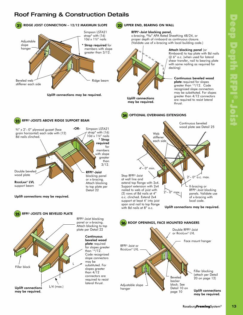
®-JoistRIDGE JoIsT connEcTIon – 12/12 MAxIMuM sloPE21
Adjustableslopehanger
SimpsonLSTA21strap*with(16)10dx1Z\x”nails
Ridgebeambeveledwebstiffenereachside
uplift connections may be required.
* strap requiredformemberswithslopegreaterthan3/12.
RFPI®-Joist blocking panel,x-bracing,XC\cx”APARatedSheathing48/24,orproperdepthofrimboardascontinuousclosure.(Validateuseofx-bracingwithlocalbuildingcode.)
continuous beveled wood platerequiredforslopesgreaterthan1/4/12.Coderecognizedslopeconnectorsmaybesubstituted.Forslopesgreaterthan4/12connectorsarerequiredtoresistlateralthrust.
uplift connections may be required.
uPPER EnD, bEARInG on WAll22
Attach blocking panel(orRimboard)totopplatewith8dnails@6”o.c.(whenusedforlateralsheartransfer,nailtobearingplatewithsamenailingasrequiredfordecking)
Roof Framing & Construction Details
C\v”x2’–0”plywoodgusset(facegrainhorizontal)eachsidewith(12)8dnailsclinched.
RFPI®-Joistblockingpanelorx-bracing.AttachblockingtotopplateperDetail22
Doublebeveledwoodplate
uplift connections may be required.
RigidLam® lVlsupportbeam
RFPI®-JoIsTs AboVE RIDGE suPPoRT bEAM23
RFPI®-JoIsTs on bEVElED PlATE25
continuous beveled wood plate requiredforslopesgreaterthan1/4/12.Coderecognizedslopeconnectorsmaybesubstituted.Forslopesgreaterthan4/12connectorsarerequiredtoresistlateralthrust.
RFPI®-Joistblockingpanelorx-bracing.AttachblockingtotopplateperDetail22
Fillerblock
SimpsonLSTA21strap*with(16)10dx1Z\x”nails
* strap required
formemberswithslopegreaterthan3/12.
-OR-
uplift connections may be required.
L/4(max.)
L
oPTIonAl oVERhAnG ExTEnsIons24
uplift connections may be required.
Webstiffenereachside
ContinuousbeveledwoodplateseeDetail25
StopRFPI®-Joistatwalllineandextendtopflangewith2x4.Supportextensionwith2x4nailedtowebofjoistwith(2)rowsof8dnailsat4”o.c.clinched.Extend2x4supportatleast4’intojoistspanandnailtotopflangewith8dnailsat8”o.c.
X-bracingorRFPI®-Joistblockingpanels.Validateuseofx-bracingwithlocalcode.
4’–0”min.
2’–0”o.c.max.
2’–0”max.
RooF oPEnInGs, FAcE MounTED hAnGERs26
uplift connections may be required.
RFPI®-JoistorRigidLam® LVL
Adjustableslopehanger
beveledbackerblock.SeeDetail10onpage10
DoubleRFPI®-JoistorRigidLam® LVL
Facemounthanger
Fillerblocking(attachperDetail20onpage12)

14 RoseburgFramingSystem®
Dee
p D
epth
RFP
I®-J
oist
RFPI-JoIsT TyPIcAl holEs - see “hoW To usE holE chART” below
holE chART - 40 PsF live load and 25 PsF Dead load onlyMInIMuM DIsTAncE FRoM InsIDE FAcE oF nEAREsT JoIsT suPPoRT To cEnTER oF holE (1) (2)
Holes For RFPI®-Joists Used In Floor/Roof Applications
notes:
1. Distancesinthisholechartareconservativelybasedonuniformly loaded joistsandthemaximumallowedsingleormulti-spanapplicationswith40live/25deadaton-centerspacingsof12”,16”,19.2”or24”.holes that fall outside of these hole chart guidelines (e.g. floors with concen-trated loads) may still be acceptable based on actual span and loading conditions.Themostaccuratemethodofdeterminingtheacceptabilityofagivenholeistheuseofappropriatesoftware(e.g.RFP-Keybeam®byKeymarkEnterprises,LLC)orengineeringanalysisfortheactualcondition.
2. Holelocationdistanceismeasuredfrominsidefaceofnearestsupporttocenterofhole.3. UseKeyMarksoftwaretoanalyzeductchaseopenings.
Joistdesignation
RoundHolediameter(in.)2 3 4 5 6 7 8 9 10 11 12 13 14 15 16 17 18 19 20
minimumdistancefromInsideFaceofnearestsupporttocenterofHole(ft-in.)(1)(2)
18”RFPI700 0'-7" 0'-8" 0'-8" 1'-4" 2'-5" 3'-7" 4'-9" 6'-0" 7'-3" 8'-8" 10'-4" 12'-4" 15'-0"
20”RFPI700 0'-7" 0'-8" 0'-8" 0'-9" 0'-10" 1'-11" 3'-0" 4'-4" 5'-9" 7'-2" 8'-8" 10'-3" 11'-11" 14'-3" 16'-10"
22”RFPI700 0'-7" 0'-8" 0'-8" 0'-9" 0'-9" 0'-10" 1'-8" 3'-0" 4'-4" 5'-8" 7'-1" 8'-6" 10'-0" 11'-6" 13'-5" 15'-11" 18'-6"
24”RFPI700 0'-7" 0'-8" 0'-8" 0'-9" 0'-9" 0'-10" 0'-10" 1'-7" 2'-10" 4'-2" 5'-5" 6'-9" 8'-1" 9'-8" 11'-5" 13'-1" 15'-3" 17'-8" 20'-2"
18”RFPI900 0'-7" 1'-3" 2'-6" 3'-9" 5'-1" 6'-5" 7'-9" 9'-2" 10'-7" 12'-0" 13'-10" 15'-9" 17'-9"
20”RFPI900 0'-7" 0'-8" 1'-7" 2'-9" 4'-0" 5'-2" 6'-5" 7'-11" 9'-6" 11'-1" 12'-9" 14'-6" 16'-4" 18'-6" 20'-9"
22”RFPI900 0'-7" 0'-11" 1'-11" 3'-0" 4'-2" 5'-3" 6'-4" 7'-6" 9'-0" 10'-5" 11'-11" 13'-6" 15'-1" 17'-0" 19'-0" 21'-1" 23'-10"
24”RFPI900 0'-7" 0'-8" 1'-3" 2'-3" 3'-4" 4'-8" 5'-11" 7'-3" 8'-7" 9'-11" 11'-3" 12'-8" 14'-2" 15'-8" 17'-5" 19'-5" 21'-10" 24'-4" 27'-0"
below
Knockouts:Seenotes7and8below.Do noThammerholesinweb,exceptatknockouts.
RulEs FoR cuTTInG holEs1. Seechartforallowableholesizesand
locations.Thedistancebetweentheinsideedgeofthesupportandthecenterlineofanyholeshallnotbelessthanthatshowninthechart.
2. Exceptforcuttingtolength,NEVERcut,drillornotchI-joistflanges.
3. Wheneverpossiblecenterholesverticallyinthemiddleoftheweb.However,holesmaybelocatedverticallyanywhereinthewebprovidedaminimumof1/8”ofwebremainsbetweentheedgeoftheholeandtheflanges.
4. ThemaximumsizeholethatcanbecutintoanI-joistwebshallequalthecleardistancebetweentheflangesoftheI-joistminus1/4”.Aminimumof1/8”shouldalwaysbemaintainedbetweenthetoporbottomoftheholeandtheadjacentI-joistflange.
5. Thesidesofsquareholesorlongestsideofrectangularholesshouldnotexceed
threefourthsofthediameterofthemaximumroundholepermittedatthatlocation.DONOTover-cutthesidesofsquareorrectangularholes.
6. Wheremorethanoneholeisnecessary,thedistancebetweenadjacentholeedgesmustbeaminimumoftwicethediameterofthelargestroundholeortwicethesizeofthelargestsquarehole(ortwicethelengthofthelongestsideofthelongestrectangularhole)andeachholemustbesizedandlocatedincompliancewiththerequirementsofthechart.
7. Knockoutsareprescoredholesforthecontractor’sconveniencetoinstallelectricalorsmallplumbinglines.Theyare1-1/2”indiameter,andarespacedapproximately16”oncenteralongthelengthoftheI-joist.Wherepossible,itispreferabletouseknockoutsinsteadoffieldcuttingholes.Forfloorapplications,positioningtheI-joistssotheknockouts
areallonthebottomofthejoist,mayeasetheinstallationofelectricalwiringorresidentialsprinklersystems.DONOThammerholesinweb,exceptatknockouts.
8. Aknockoutisnotconsideredaholeandmaybeutilizedanywhereitoccurs.Itcanbeignoredforpurposesofcalculatingminimumdistancesbetweenholes.
9. 1½”holesshallbepermittedanywhereinacantileveredsectionofanRFPI-Joist.Holesofgreatersizemaybepermittedsubjecttoverification.
10. A1½”holecanbeplacedanywhereinthewebprovidedthatitmeetstherequirementsofrule6onthispage.
11. Agroupofroundholesatapproximatelythesamelocationshallbepermittediftheymeettherequirementsforasingleroundholecircumscribedaroundthem.
12. Allholesshallbecutinaworkman-likemannerinaccordancewiththerestrictionslistedherein.
hoW To usE holE chART
1. ReadacrossthetopofHoleCharttothedesiredholesize.
2. FollowthiscolumndowntotherowthatrepresentstheI-joistdepthanddesignation.Thisnumberindicatestheminimumdistancefromthefaceofthesupporttothecenterlineofthehole.
Example:Needa13½-inchholeina20”RFPI®-900joist:
FromHoleChart,
Fora13-inchroundhole,theminimumdistanceis14’–6”.Fora14-inchroundhole,theminimumdistanceis16’–4”.Thereforetheminimumdistanceforthe13½-inchroundholeis15’–5”(halfwaybetween14’-6”and16’-4”).
IMPoRTAnT: HoleChartisapplicableforUniformLoadsof40psfLiveLoadand25psfDeadLoadONLY.

RoseburgFramingSystem® 15
Deep
Dep
th R
FPI
®-JoistonE-houR FIRE-RATED AssEMblIEs WITh APA PERFoRMAncE RATED I-JoIsTs
WoodI-joistshavebeenusedsuccessfullyinfire-ratedfloorassembliesformanyyears.SeveralI-joistfire-ratedassemblies(1-hourand2-hour)havebeenpublishedthatareapplicabletoI-joiststhatmeetorexceedtherequiredspecificationsprovidedinthefire-ratedassemblydescription.These“generic”assembliescanbefoundintheAmericanWoodCouncil(AWC)publicationentitled“DesignforCodeAcceptance3”(DCA3).MostoftheseDCA3assemblieshavebeenadoptedbytheInternationalbuildingCode(IbC)andcanbefoundinTable720.1(3)ofthe2006and2009IbC.Additionalfire-ratedsystemsandassociatedinformationcanbefoundintheAPAICC-EScodereportESR-1405andvariousotherAPApublications.TheRoseburgICC-ESI-joistcodereport,ESR-1251,liststhevariousIbCandAPAfire-ratedfloor-ceilingassembliesforwhichRFPI-Joistshavespecificcodeapproval.Thewebsiteaddressesforthesepublicationsareasfollows:
noIsE-RATED FlooR AssEMbly WITh APA PERFoRMAncE RATED I-JoIsTs
Padandcarpet
1Z\x”lightweightconcrete
C\v”APARatedSheathing
B\,”gypsumwallboard
I-Joistspacedamaximumof24”o.c. Resilientsteelchannels
spaced24”o.c.
3”glassfiber
Fire & Sound Rated Floor Assemblies
(1)TestshaveshownthatsubstitutionofOSborcompositeAPARatedSturd-I-Floorforplywoodpanelsinfire-ratedsingle-layerassemblieswillnotjeopardizefire-resistanceratings.Substitutionisbasedonequivalentpanelthickness.OSbpanelsarelistedasalternatestoplywoodforfinishflooringinaccordancewithproductevaluationreportsforAPAPRItrademarkedI-joists.
(2)Forimprovedacousticalperformance,gypsumwallboardisfastenedtoresilientmetalfurringchannelsinsomeassemblies.
(3)ConstructionadhesivemustconformtoAPASpecificationAFg-01,orASTMD3498.
ConstructionadhesiveatsupportsandT&gedges(3)
I-Joistspacedamaximumof24”o.c.
Resilientsteelchannelsspaced16”o.c.(2)
Z\x”TypeXgypsumwallboardceiling(2layers)
XC\cx”T&gAPAwoodstructuralpanels(1)
sounD RATInGs FoR FlooRs usInG APA PERFoRMAncE RATED I-JoIsTs
sPRInKlER ATTAchMEnT -SeeAPA-TheEngineeredWoodAssociationpublicationJ745“SprinkerPipeInstallationforAPAPerformanceRatedI-Joists”forsprinklerattachmentguidelines.
(1)USDAForestServiceWoodConstructionResearch(Seattle,WA);acousticaltestsbygeiger&Hamme,Inc.(AnnArbor,MI)
testsponsorandnumber1 Floor deck gypsum
wallboardceiling Insulation stcRating
IIcRating
weight(lbs./sq.ft.)
g&HUSDA11ST VinylTile 1-1/2”of100-pcfcellularconcreteover3/4”APARatedSheathingsubflooronI-joistat24”o.c.
5/8”screwedtoresilientmetalchannels
3”glassfiber58 50
21.0
g&HUSDA11xSTCarpet&Pad 58 77
None None 57 None 20.7
2006 Ibc Table 720.1(3)
2009 Ibc Table 720.1(3)
APA Icc-Es Report EsR-1405
American Wood council DcA3
APA “Fire Rated systems” W305
DurationRFPI-Joist series that meet the
assembly requirementsItem21-1.1 Item21-1.1 Assembly2 - - 1hr. AllRFPIseriesItem23-1.1 Item23-1.1 - WIJ-1.3 Fig.4.3C 1hr. AllRFPIseriesItem25-1.1 Item24-1.1 - WIJ-1.1 Fig.4.3A 1hr. RFPI90&900Item26-1.1 Item25-1.1 - WIJ-1.2 Fig.4.3b 1hr. RFPI90&900Item27-1.1 Item26-1.1 - WIJ-1.5 Fig.4.3E 1hr. RFPI40S,60S,70,90,700&900Item28-1.1 Item27-1.1 - WIJ-1.6 Fig.4.3F 1hr. AllRFPIseries
- - - WIJ-1.4 Fig.4.3D 1hr. RFPI40S,60S,70,90,700&900- - - WIJ-1.7 - 1hr. RFPI40S,60S,70,90,700&900- - Assembly1 - - 1hr. RFPI40S,60S,90,&900- - Assembly3 - - 1hr. AllRFPIseries
Item29-1.1 Item28-1.1 - WIJ-2.1 Fig.5 2hr. RFPI40S,60S,70,90,700&900
Thenoise-ratedassemblyshownbelowisoneofseveralassembliesthatcanbeusedwithI-Joists.ForadditionalSTCandIICsoundratingsystems,refertotheAWCandAPApublicationsnotedabove.AdditionalgeneralinformationregardingSTCandIICsoundratingscanbefoundinAPAFormNo.W460atthefollowingwebsite:(http://apawood.org/publications)SearchforpublicationW460.
Roseburg:•ICCESReportESR-1251 (www.icc-es.org/reports/pdf_files/ICC-ES/ESR-1251.pdf)AWC: •DCA3 (www.awc.org/Publications/dca/dca3/DCA3.pdf)APA: •ICCESReportESR-1405 (www.icc-es.org/reports/pdf_files/ICC-ES/ESR-1405.pdf) •FormNo.W305forI-Joists (www.apawood.org/publications) SearchforpublicationW305 •FormNo.D350forRimboard (www.apawood.org/publications) SearchforpublicationD350
Thefire-ratedassemblyshownatleftisoneofthemorecommonassembliesshowninDCA3(WIJ-1.6)andpublishedinthe2006IbC(Item28-1.1)and2009IbC(Item27-1.1)andcanbeusedwithanyoftheRFPI®-Joistseriesanddepths.

16 RoseburgFramingSystem®
Rig
idla
m® l
vl Available RigidLam® LVL Grades and Sizes*
RigidLam® LVL Allowable Design Stresses1
RIGIDlAM lVl GRADEs: 1.3E,1.5Eand2.0E
RIGIDlAM lVl ThIcKnEssEs: 1-1/2”,1-3/4”,3-1/2”,5-1/4”and7”
RIGIDlAM lVl DEPThs: 3-1/2”,4-3/8”,5-1/2”,7-1/4”,9-1/4”,9-1/2”, 11-1/4”,11-7/8”,14”,16”,18”,20”,22”&24”
RIGIDlAM lVl coluMn sIzEs:3-1/2”x3-1/2”,3-1/2”x5-1/2”,3-1/2”x7” 5-1/4”x5-1/4”,5-1/4”x5-1/2”,5-1/4”x7” 7”x7”*Notallgradesand/orsizesavailableinallmarkets.ContactyourRoseburgEWPrepresentativeforavailability.
1.3E Rigidlam lVl 1.5E Rigidlam lVl 2.0E Rigidlam lVl
ModulusofElasticity(MOE)2–EdgewiseorFlatwise E(psi)= 1,300,000 1,500,000 2,000,000
bending–Edgewise3,4 Fbedge(psi)= 2,250 2,250 2,900
bending–Flatwise Fbflat(psi)= 2,250 2,250 2,900
HorizontalShear-Edgewise Fvedge(psi)= 200 220 285
HorizontalShear-Flatwise Fvflat(psi)= 130 130 130
CompressionPerp.Tograin2-Edgewise Fcperpedge(psi)= 560 575 750
CompressionPerp.Tograin2-Flatwise Fcperpflat(psi)= 500 500 500
CompressionParalleltograin Fcpara(psi)= 1,950 1,950 2,750
TensionParalleltograin5 Ft(psi)= 1,500 1,500 1,900
MOEforstabilitycalculations2 Emin(psi)= 660,660 762,300 1,016,400
1. Theseallowabledesignstressesapplytodryserviceconditions.2. Noincreaseisallowedfordurationofload.3. Fordepthsotherthan12”multiplyFbby(12/d)
1/8whered=depthofmember(in).4. Afactorof1.04maybeappliedforrepetitivemembersasdefinedintheNational
DesignSpecificationforWoodConstruction.5. Tensilestressisbasedona4-footgagelength.Forgreaterlengths,multiplyFtby(4/L)1/9whereL=lengthinfeet.Forlengthslessthan4feet,usethepublishedvalue.
MInIMuM nAIl sPAcInG FoR RIGIDlAM lVl bEAMs
Perpendiculartogluelines
Paralleltogluelines
Ifmorethanonerowofparallelnailsisrequiredforendandedgenailing,therowsmustbeoffsetatleast1/2”andstaggered.
nail sizeMinimum Parallel spacing
Minimum Parallel End
Distance
Minimum Perpendicular
spacing
8d box 3” 1-1/2” 2”8d common 3” 2” 2”
10d & 12d box 3” 2” 2”10d & 12d common 4” 3” 3”
16d sinker 4” 3” 3”16d common 6” 4” 3”
PERMIssAblE hoRIzonTAl RounD holE locATIon FoR RIGIDlAM® lVl bEAMs
d
¹⁄₃ d
¹⁄₃ d
¹⁄₃ d
2¹⁄₂ d2¹⁄₂ d
•Forbeamdepths(d)of4-3/8,5-1/2,and7-1/4inches,themaximumholediameteris1,1-1/8,and1-1/2inches,respectively.
•Fordeeperbeams,themaximumholediameteris2inches.•Diagramappliesforsimpleandmulti-spanapplicationswithuniformloading.•Nomorethan3holesperspanarepermitted.•Holesshouldnotbecutincantilevers.
Minimumhorizontalspacing=2xdiameterofthelargesthole
=Zonewherehorizontalholesarepermittedforpassageofwires,conduit,etc.
sToRAGE, hAnDlInG & InsTAllATIon
• DoNotdropRigidLamLVLoffthedeliverytruck.bestpracticeisuseofaforkliftorboom.
• RigidLamLVLshouldbestoredlyingflatandprotectedfromtheweather.
• Keepthematerialaminimumof6”abovegroundtominimizetheabsorptionofgroundmoistureandallowcirculationofair.
• bundlesshouldbesupportedevery10’orless.
• RigidLamLVLisforuseincovered,dryconditionsonly.Protectfromtheweatheronthejobsitebothbeforeandafterinstallation.
• 1-1/2”x14”anddeeperand1-3/4”x16”anddeepermustbeaminimumoftwopliesunlessdesignedbyadesignprofessionalforaspecificapplication.
• RigidLamLVLheadersandbeamsshallnotbecut,notchedordrilledexceptasshownbelow.Heelcutsmaybepossible.ContactyourRoseburgForestProductsrepresentative.
• ItispermissibletoripRigidLamLVLtoanon-standarddepthprovideditisstructurallyadequatefortheappliedloads(non-standarddepthsmaybeanalyzedusingKeybeamsoftware).
• ProtectRigidLamLVLfromdirectcontactwithconcreteormasonry.
• EndsofRigidLamLVLbearinginconcreteormasonrypocketsmusthaveaminimumof1/2”airspaceontop,sidesandend.
• DoNotinstalldamagedRigidLamLVL.
• DoNotwalkonbeamsuntiltheyarefullybraced,orseriousinjuriesmayresult.
MoIsTuRE REPEllEnT sEAlERRigidLamLVLiscoatedwithawax-basedmoisturerepellentsealerthatisformulatedspecificallyforLVL.ItisappliedtoallsixsidesoftheLVLduringthemanufacturingprocess.Afterthesealerdries,itisinertandclearinappearance.

RoseburgFramingSystem® 17
Rig
idla
m® lv
lRigidLam LVL Bearing Details bEAM-To-bEAM connEcTIon
Makesurehangercapacityisappropriateforeachapplication.Hangersmustbeproperlyinstalledtoaccommodatefullcapacity.
bEARInG on sTEEl coluMn
Verifytherequiredbearinglengthandtheabilityofthesupportingcolumnmembertoprovideadequatestrength.
bEARInG on ExTERIoR WAll
Checkforproperbeambearinglengthbasedonplatematerial.
bEARInG on WooD coluMn
Verifytherequiredbearinglengthandtheabilityofthesupportingcolumnmembertoprovideadequatestrength.
Fastening Recommendations For Multiple Ply Members
bEARInG FoR DooR oR WInDoW hEADER
Installtheappropriatenumberofjackstudstoproviderequiredbearinglength.
ToP loADED MEMbERs
•For12”deep(orless)members,nailpliestogetherwith2rowsof16dx3½”com.nailsat12”o.c.(add1rowfor16dsinkers).
•For14”,16”or18”deepmembers,nailpliestogetherwith3rowsof16dx3½”com.nailsat12”o.c.(add1rowfor16dsinkers).
•For20”,22”or24”deepmembers,nailpliestogetherwith4rowsof16dx3½”com.nailsat12”o.c.(add1rowfor16dsinkers). 2-Ply 3-Ply 4-Ply
PocKET consTRucTIonProvide1/2”airspaceontop,sidesandendofRigidLamLVLbeams.
ProvidemoisturebarrierbetweenRigidLamLVLbeamsandconcrete.
2”minrecommended
Equalspaces+/-
MAxIMuM unIFoRM loAD APPlIED To EIThER ouTsIDE PIEcE - PounDs PER lInEAl FooT
1-1/2” Thick Pieces in Member
nail size
nailed bolted
2 rows 10d common at 12” o.c.
3 rows 10d common at 12” o.c.
2 rows 1/2” bolts at 24” o.c.
2 rows 1/2” bolts at 12” o.c.
3 rows 1/2” bolts at 12” o.c.
1.3E & 1.5E lVl
2.0E lVl1.3E &
1.5E lVl2.0E lVl
1.3E & 1.5E lVl
2.0E lVl1.3E &
1.5E lVl2.0E lVl
1.3E & 1.5E lVl
2.0E lVl
2-1-1/2” 10dcom.(0.148”x3”) 465 465 700 700 395 435 795 870 1190 13053-1-1/2” 10dcom.(0.148”x3”) 350 350 525 525 295 325 595 650 895 9804-1-1/2” usebolts - - - - 265 290 530 580 795 870
1-3/4” Thick Pieces in Member
nail size
nailed bolted
2 rows 16d common at 12” o.c.
3 rows 16d common at 12” o.c.
2 rows 1/2” bolts at 24” o.c.
2 rows 1/2” bolts at 12” o.c.
3 rows 1/2” bolts at 12” o.c.
1.3E & 1.5E lVl
2.0E lVl1.3E &
1.5E lVl2.0E lVl
1.3E & 1.5E lVl
2.0E lVl1.3E &
1.5E lVl2.0E lVl
1.3E & 1.5E lVl
2.0E lVl
2-1-3/4” 16dcom.(0.162”x3-1/2”) 560 560 845 845 460 505 925 1015 1390 15203-1-3/4” 16dcom.(0.162”x3-1/2”) 420 420 635 635 345 380 695 760 1040 11404-1-3/4” usebolts - - - - 305 335 615 675 925 10152-3-1/2” usebolts - - - - 820 860 1640 1720 2465 2580
REcoMMEnDED FAsTEnER DEsIGn InFoRMATIon In TERMs oF EQuIVAlEnT sPEcIFIc GRAVITy FoR hEADER GRADEs oF 1.5E AnD 2.0E RIGIDlAM lVl
Face Edge
1.3E & 1.5E lVl
2.0E lVl1.3E &
1.5E lVl2.0E lVl
Withdrawal - nail 0.50 0.50 0.47 0.50
Dowel bearing - nail 0.50 0.50 0.47 0.50
Dowel bearing - bolt 0.47 0.50 Notapplicable
• UseRFP-Keybeam®sizingsoftwareorbeam/headerchartsorplfloadtablestosizethebeam.
• Thetablevaluesapplytocommon(A307)bolts.boltholesmustbecenteredatleasttwoinchesfromthetopandbottomedgesofthebeam.boltholesmustbethesamediameterasthebolts.Washersmustbeusedundertheboltheadsandnuts.Offsetorstaggerrowsofboltholesbyone-halfoftheboltspacing.
• Thespecifiednailingappliestobothsidesofathree-piecebeam.• 7inchwidebeamsmaynotbeloadedfromonesideonly.Theymustbeloadedfrombothsidesand/ortop-loaded.
• Thesideloadedtablevaluesfornailsmaybedoubledfor6”o.c.spacingandtripledfor4”o.c.spacing.
• Durationofloadfactors(e.g.115%,125%etc...)maybeappliedtothetablevalues.
sIDE loADED MEMbERs

18 RoseburgFramingSystem®
Rig
idla
m® l
vl
Screw length(in decimal)
Strong-Drive®
screw identifier and diameter
X . X X
W22
³⁄₄"
L
0.22" TL
L1
T
L
TL
Fastening Recommendations For Multiple Ply LVL Members (cont.)
• ThewoodscrewslistedbelowareapprovedforuseinconnectingmultiplepliesofRigidLam®LVLtogetherandmaybeusedasanalternativetothenailingorboltingguidelinesonthepreviouspage.
• Pre-drillingoftheLVLmembersisnotrequiredforthescrewslistedbelow.• Carefullyreviewandadheretothedesignandinstallationinformationavailablefromeachofthescrewmanufacturerslistedbelow.
Thediagramsaboveareforillustrativepurposesonly,screwsmayneedtobeappliedtobothsides.Refertothemanufacturers’informationfortheappropriatedesignandinstallationguidelines.
Simpson SDW Wood Screws
Simpson SDS Wood Screws
USP WS Wood Screws
FastenMaster TrussLok Wood Screws
Model no. l (in) Tl (in) head stamp length
SDW22338 3-3/8 1-9/16 3.37SDW22500 5 1-9/16 5.00SDW22634 6-3/4 1-9/16 6.75
Model no. l1 (in) T (in) head stamp
SDS25312 3-1/2 2-1/4 S3.5SDS25412 4-1/2 2-3/4 S4.5SDS25600 6 3-1/4 S6
Model no. l (in) sh (in) T (in)
WS35 3-1/2 1 2-1/2WS6 6 1-3/4 4-1/4
Model no. l (in) Tl (in) head Marking
FMTSL338 3-3/8 1-1/2 F3.3FMTSL005 5 1-1/2 F5.0FMTSL634 6-3/4 1-1/2 F6.7
• CodeEvaluationReportpending
• ForSDWdesignandinstallationinformation,refertothecurrentSimpsonStrong-Tieliterature,www.strongtie.comorcontactSimpsonStrong-Tieat800-999-5099.
• CodeEvaluationReport–ICC-ESESR-2236
• ForSDSdesignandinstallationinformation,refertothecurrentSimpsonStrong-Tieliterature,www.strongtie.comorcontactSimpsonStrong-Tieat800-999-5099.
• CodeEvaluationReport–ICC-ESESR-2761
• ForWSdesignandinstallationinformation,refertothecurrentUSPStructuralConnectorsliterature,www.uspconnectors.comorcontactUSPStructuralConnectorsat800-328-5934.
• CodeEvaluationReport–ICC-ESESR-1078
• ForTrussLokdesignandinstallationinformation,refertothecurrentFastenMasterliterature,www.fastenmaster.comorcontactFastenMasterat800-518-3569
ForhangerinformationrefertothecurrentSimpsonStrong-Tieliterature,www.strongtie.comorcontactSimpsonStrong-Tieat800-999-5099
ForhangerinformationrefertothecurrentUSPStructuralConnectorsliterature,www.uspconnnectors.comorcontactUSPStructuralConnectorsat800-328-5934

RoseburgFramingSystem® 19
(1)Alldesignpropertiesassume: •Maximumjoistspacingof24”on-center•Maximumjoistdepthof16”•Rimboardnailingof8dnails@6”on-center
(2) Alldesignvalues,exceptHorizontalLoad,arebasedonlong-termloadduration(100%)andmaybeadjustedforotherloaddurationsinaccordancewiththeapplicablecode.HorizontalLoadmaynotbeadjustedfordurationofload.
(3) Horizontalloadmaybeincreasedto330PLFwhenRimboardnailingof8dcom.nails@4”on-centerisused.
(4)The16d(boxorcommon)nailsusedtoconnectthebottomplateofa walltotheRimboardthroughthesheathingdonotreducethe horizontalloadcapacityoftheRimboardprovidedthatthe8dnail spacing(sheathingtoRimboard)is6”o.c.andthe16dnailspacing (bottomplatetosheathingtoRimboard)isinaccordancewiththe prescriptiverequirementsoftheapplicablecode.(5)For1-1/4”RigidRimRimboardSiesmic,theallowablePostLoadis 5900lbs.fordepths16”orless.
(1)Allowableedgewisebendingstressisapplicableonlytoaspanof4’orless(2) Applicableforlengthsupto14ft.(3) CompressionPerpendiculartograinvaluemaynotbeincreasedfordurationofload
RigidRim® OSB Rim Board SpecificationsAsacomponentoftheRoseburgFramingSystem®,RigidRim®OSbRimboardallowsyourcustomerstoquicklyframetheperimeteroftheirfloorsystemandisoneofthemostcosteffectivemethodstoproperlytransferverticalandhorizontalloadsaroundtheI-joistanddirectlyintothesupportingwalls.
RigidRimOSbRimboardiscurrentlyavailableintwothicknessesandthreegrades:
11/8”RigidRim®OSbRimboard 11/8”RigidRim®OSbRimboardPlus11/4”RigidRim®OSbRimboardSeismic
(AinsworthDurastrand)
TheRigidRim®OSbRimboardproductsareavailableinlengthsupto24-ft.AllRigidRimOSbRimboardproductsareavailableinallofthedeepI-joistdepths.
AllthreeproductsaremanufacturedinaccordancewithICCEvaluationService,Inc.AcceptanceCriteriaForRimboardProducts(AC124)andPRR-401,PerformanceStandardforAPAEWSRimboards.Ainsworth11/4”Durastrand®RimboardhasanICCESReport(ESR-1210)andcanalsobedesignedforedgewisebendingapplicationstosupportloadsoverwindowanddooropenings.ForadditionalinformationregardingspanningwindowanddooropeningsandcuttingholesinRimboard,refertotheAPAPublications“I-JoistConstructionDetails”(FormD710)and“APAPerformanceRatedRimboard”(FormW345g).
Roseburg’sRimboardisdimensionallystableandresistsshrinkingandwarping.Italsoprovidesasmoothnailingsurfacefortheattachmentofexteriorsheathing,sidingandledgers.Refertopage8foradditionalframinginformation.
RigidRim Rim board Design Properties (1)(2)(4)
Panel Thickness
Vertical load (PlF) Depth ≤ 16”
Vertical load (PlF) 16”< Depth ≤ 24”
horizontal load (PlF)
Post load (Pounds)
Depth ≤ 24”
lag screw (1/2”) (Pounds)
osb RigidRim Rim board 1-1/8” 4400 3000 180(8dboxorcom) 3500 350osb RigidRim Rim board Plus 1-1/8” 4850 3200 200(8dboxorcom) 3500 350osb RigidRim Rim board seismic 1-1/4” 5700 3500 240(3)(8dcom) 5500(5) 400
Rig
idR
im® o
SB R
im B
oard
RigidRim Rim board Edgewise Design Properties
Flexural stressModulus of
ElasticityTension Parallel
to Grain (2) horizontal shearcompression Perpendicular
to Grain(3)
1-1/8”OSbRimboard&RimboardPlus 600psi(1) 0.55x10⁶psi - 270psi 550psi1-1/4”OSbRimboardSeismic 1130psi 0.80x10⁶psi 680psi 355psi 1415psi
20 RoseburgFramingSystem®
RFPI®, RigidLam®, RigidRim®, RFP-KeyBeam®, RFP-KeyPLan®, RFP-KeyCoLumn®, SmartFramer™,RoseburgFramingSystem®,qualityEngineeredWoodProductsForToday’sbuilder®aretrademarksofRoseburgForestProducts,Roseburg,Oregon.
©2010RoseburgForestProducts
10599 Old Hwy 99 South | Dillard Oregon 97432tel 800-347-7260 | fax 541-679-2612
web www.Roseburg.com | email [email protected]
EffectiveOctober2010
Code report IndexROSEbURgEWPCODEREPORTS PRODUCTICCESR-1251 I-JOISTICCESR-1210 LVL&LVLRimAPAPR-L259 I-JOISTAPAPR-L289 LVLAPAPR-L270 LVLSTUDSCityofLosAngelesRR25439 I-JOISTCityofLosAngelesRR-25680 LVLDSAPA-131 I-JOISTDSAPA-136 LVL DSAAC23-1 I-JOIST FloridaFL2440 I-JOIST&LVLCCMC13323-R(Canada) I-JOISTCCMC13310-R(Canada) LVL
Thecodereportslistedaboveareavailableatwww.roseburg.com,intheEngineeredWoodProductssection,TechnicalInformation.
Roseburg Forest Products warrants that its RFPI®-Joists,
RigidLam® laminated veneer lumber (LVL) and RigidRim® Rimboard
will be free from manufacturing errors and defects in workmanship and
materials in accordance with our specifications.
Furthermore, we warrant that these products, when
properly stored, installed and used in dry use service
conditions, will meet or exceed our performance
specifications for the expected life of the structure.
10599 Old Hwy 99 South • Dillard, Oregon 97432 • 800-347-7260
RFPI®, RigidLam®, RigidRim® are registered trademarks of Roseburg Forest Products, Roseburg, Oregon.
PRODUCT & PERFORMANCE
WARRANTY
• VisitourWebsiteatwww.Roseburg.comanddownloaditdirectlytoyourcomputer.• Sendusane-mailatewpsales@rfpco.comandrequestit.WewillmailaninstallationCDtoyou.• Callusat1-800-347-7260andrequestit.
Inallcases,pleaseprovideyourname,jobtitle,companynameandaddress,phonenumberande-mailaddress.
RoseburgForestProductsoffersseveralsoftwaretoolsthatwillaideyouingeneratingaccurateandprofessionallayoutdrawingsandcalculations.ThesesoftwaretoolsincludeRFP-Keybeam®andRFP-KeyPlan®developedbyKeymarkEnterprises,LLC,acompanylongrecognizedasanindustryleaderinthedevelopmentofprogressivesoftwaresolutions.AlsoavailableistheSmartFramer™layoutsoftwaredevelopedbyRoseburg.
Software Tools
RFP-Keybeamisapowerful,yeteasytousesinglemembersizingprogramthatenablesyoutosizeRFPengineeredwoodproductsforalmostanystructuralcondition.Youprovideadescriptionofthespans,supports,andloadsofaspecificsizingproblemandRFP-Keybeamwillpresentyouwithalistofmultipleproductsolutions.Afterselectingaproductyoucanprintoutaprofessionalandeasytoreadcalcsheet.YoucanalsouseRFP-KeybeamtodetermineifaparticularI-JoistorLVLbeamworksforaspecificapplication.
TheprogramdesignsRFPI®-Joistsattheiroptimumon-centerspacingandRIgIDLAM®LVLbeamsattheiroptimumdepth.RectangularorcircularholescanalsobedesignedforRFPI-Joistsandtheprogramcandeterminethemaximumsizeholeforagivenlocation.CantileverreinforcementisautomaticallyspecifiedwhenrequiredforRFPI-Joistsusedinloadbearingcantileverapplications.
Anewsoftwaremodule,KeyColumn®,isalsoprovidedinconjunctionwiththeRFP-Keybeam.KeyColumnisasinglemembersizingsoftwareforusewithcolumnsandwallstuds.RigidLamLVLcolumnsandstudscanbesizedusinganycombinationofaxialandlateralloadingandavarietyofdefaultandcustombracingconditionsforindividualstudandcolumnmembers.
RoseburgForestProductswillprovidethispowerfulprogramtoyouatnocost.Youcanobtainitinanyofthefollowingways:
RFP-KEybEAM®
AlsoavailableisRFP-KeyPlan,thecompleteautomationsystemforengineeredwoodproducts.Withthisremarkabletool,theoperatordescribestheframinggeometryandRFP-KeyPlandoestherest.Infact,theprogramwillautomatically:
• Developloadsthroughoutthestructure• SizeallframingmembersforRFPengineeredwoodproducts• Selecthangers• generateplacementplans• generateinventorymanagement,cutoptimization,&materialconsolidation
Keymarkprovidesalltrainingandsoftwaresupportnecessarytosuccessfullylearnandimplementthesetwoprograms.YoucanobtainmoreinformationabouttheRFP-KeybeamandRFP-KeyPlansoftwaresystemsbycontactingKeymarkdirectlyat1-800-652-6050orvisitingKeymark’swebsiteatwww.keymark.com.WhiletalkingwithKeymark,makesuretoscheduleafreeinteractivesoftwaredemonstration.
RFP-KEyPlAn®
SmartFramersoftwareisaproprietary,user-friendlydraftingtoolthatallowsyoutoquicklydrawjoists,beams,rimboardandhangersforresidentialorlightcommercialapplicationsonyourcomputerandprinttheresultswithaprofessionallookingcolor-codedplot.Thesoftwareprogramalsogivesyoutheopportunitytoautomaticallygenerateamateriallistandabidsheetifdesired.SmartFramerisasimpletouselayouttool,butdoesnotcheckthestructuraladequacyoftheframingmembers.TheSmartFramersoftwareisan“add-on”modulethatrunsontheSmartSketch™drawingprogramdevelopedbyIntergraphCorporation.TheSmartSketchsoftwareisawell-establisheddraftingprogramthatyoucanpurchasedirectlyfromtheIntergraphCorporation.RoseburgwillprovidetheSmartFramermoduleatnocosttoyou.
sMARTFRAMER™