Engineer Technical Information Package - NRG: The CMU...
52
Niagara Regional Group, Ltd. Engineer Technical Information Package
Transcript of Engineer Technical Information Package - NRG: The CMU...

Niagara Regional Group, Ltd.
Engineer Technical Information Package

INDEX
Index………………..........…….….…2
Basic Cost Comparison…………..3
Basic Installation….................4
Installation Specifications….5-52
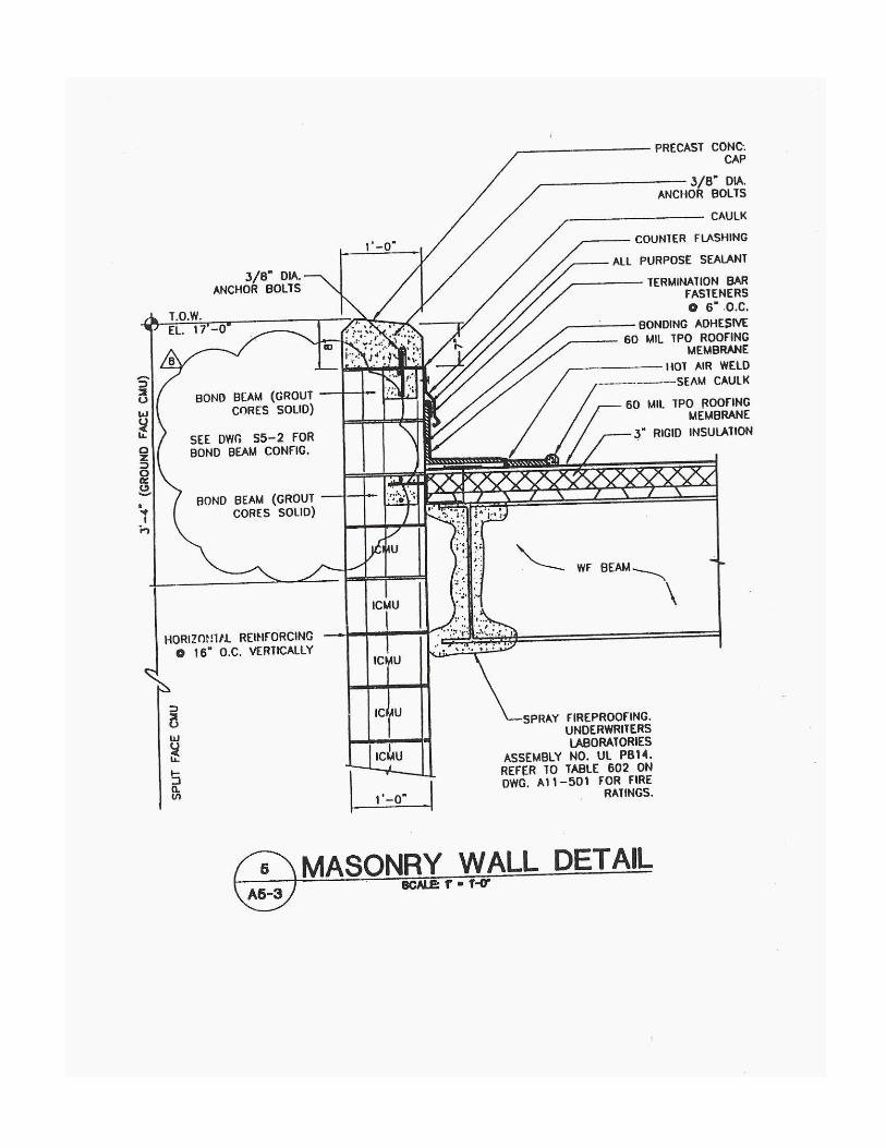
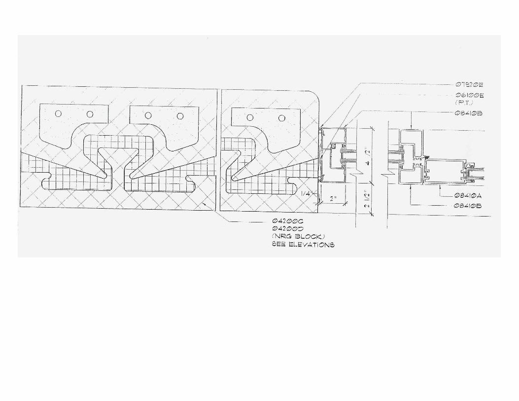
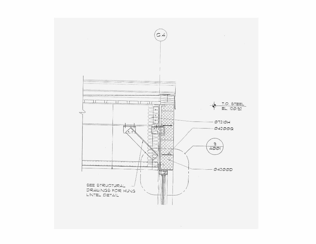
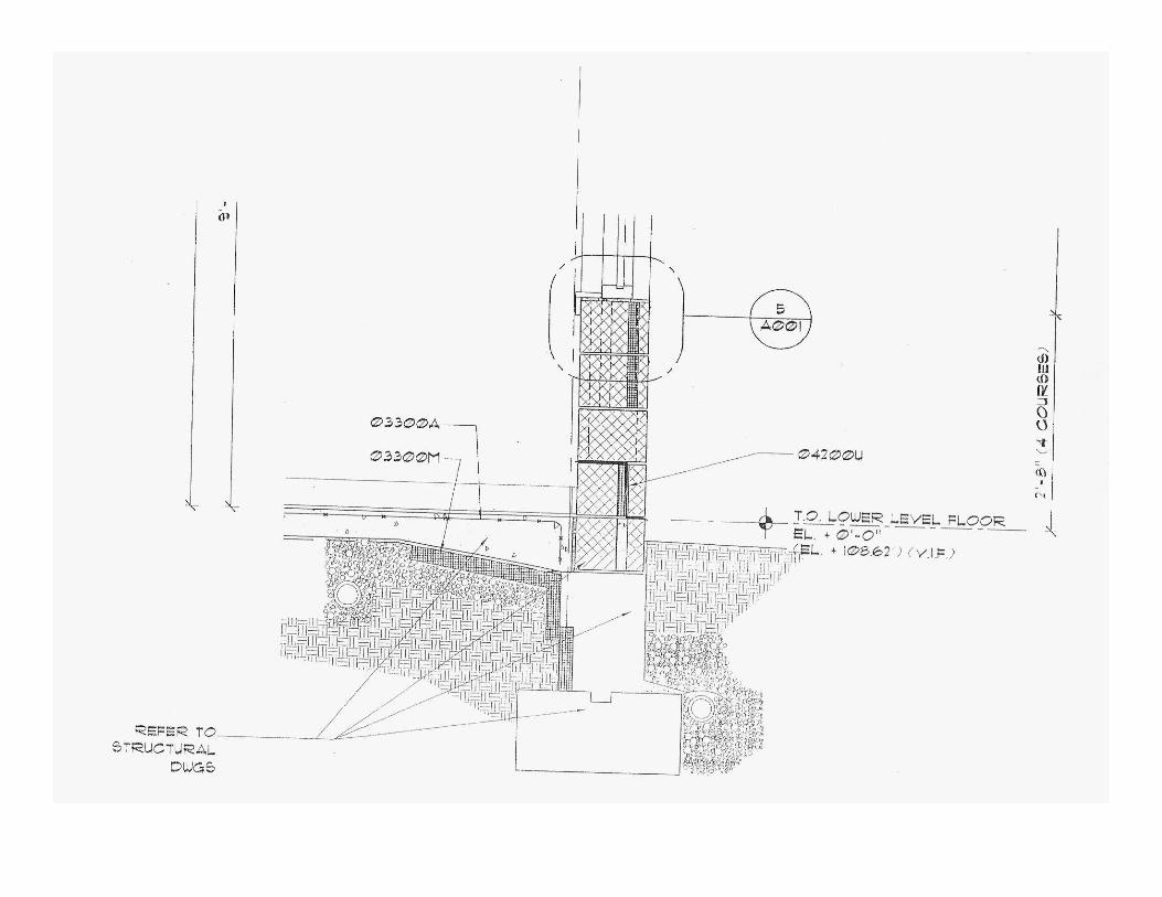
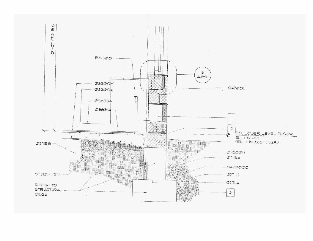
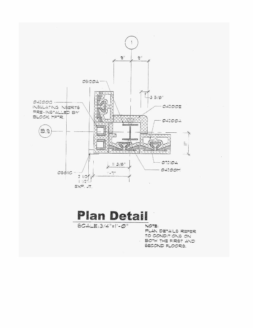
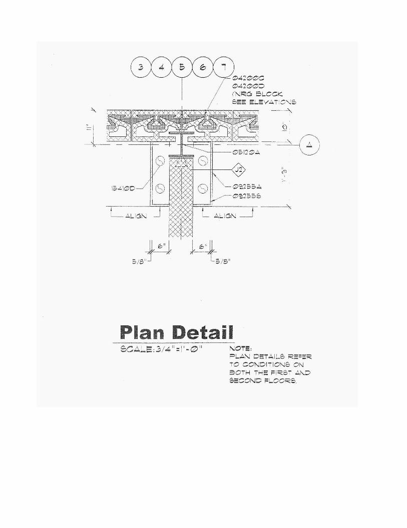
Structural Detail Drawings: door frames,
corners, alternate courses, flashing at
foundations: floating slab, trench type,
spread footing.
Flashing at walls and sills.
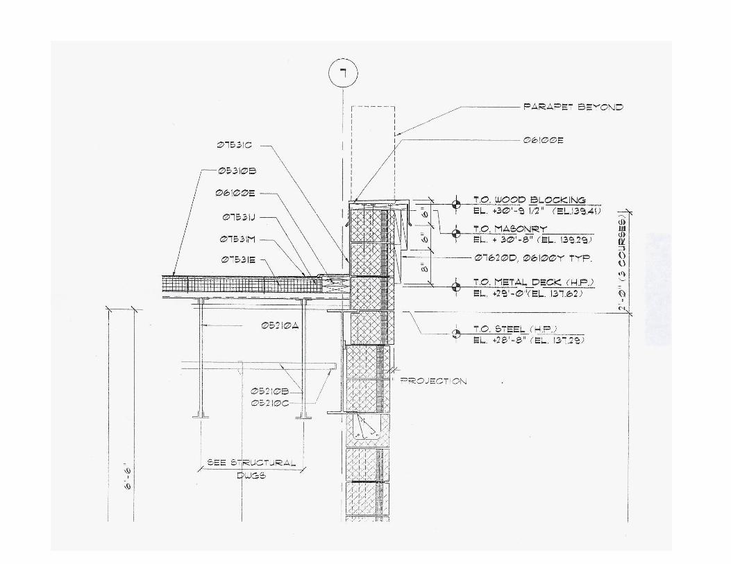
Wall details at precast floors.
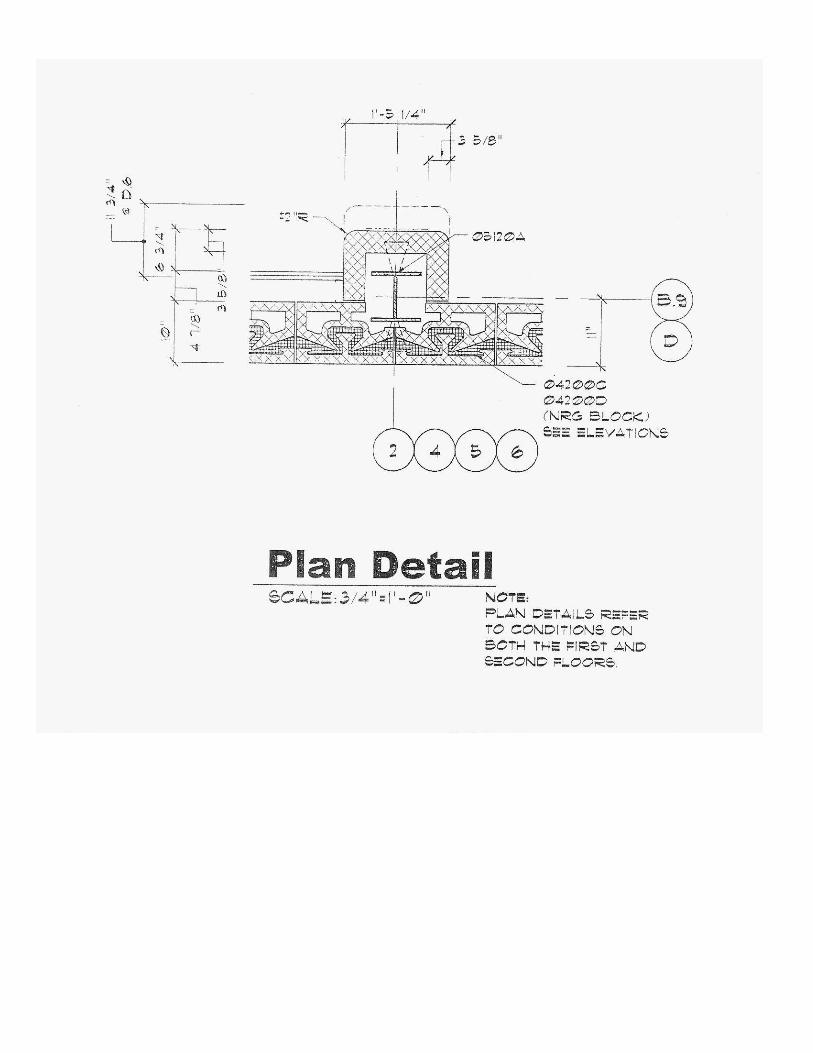
Building plan.
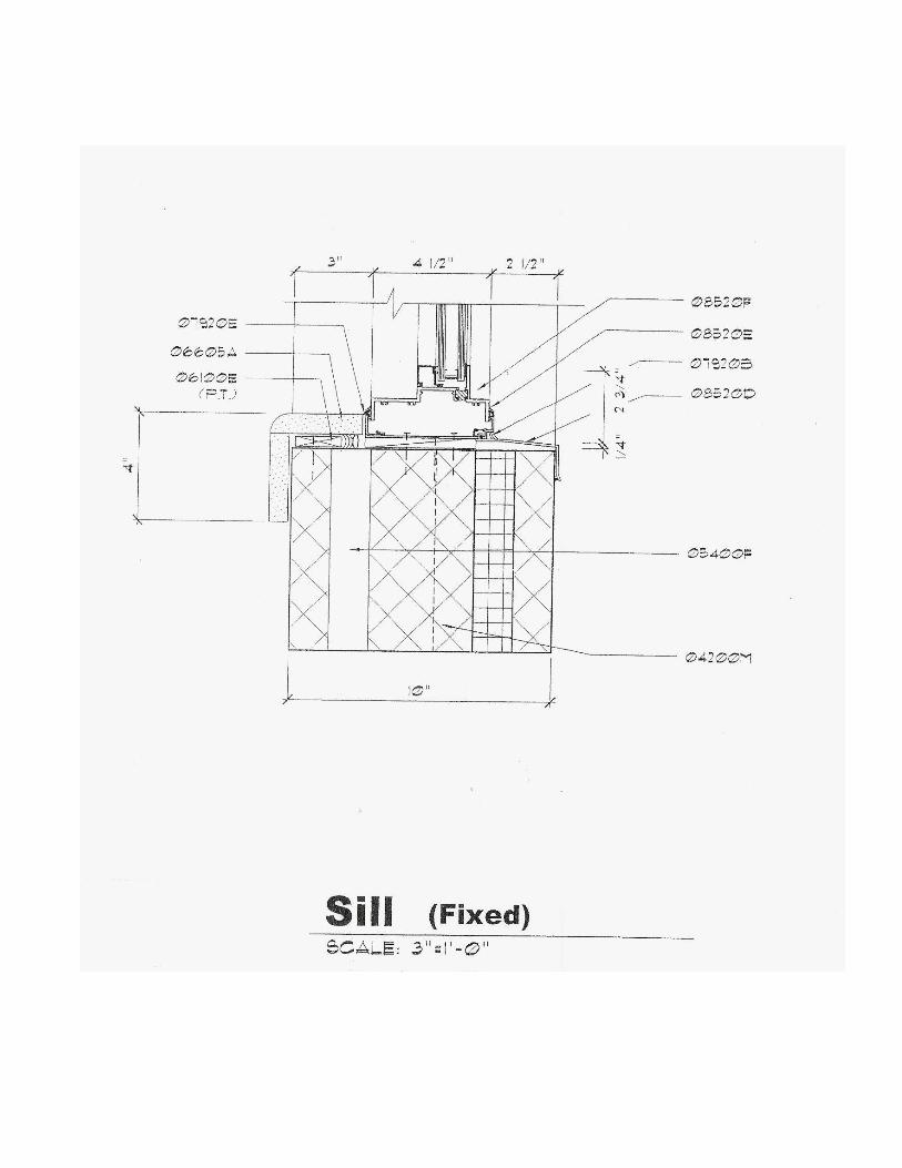
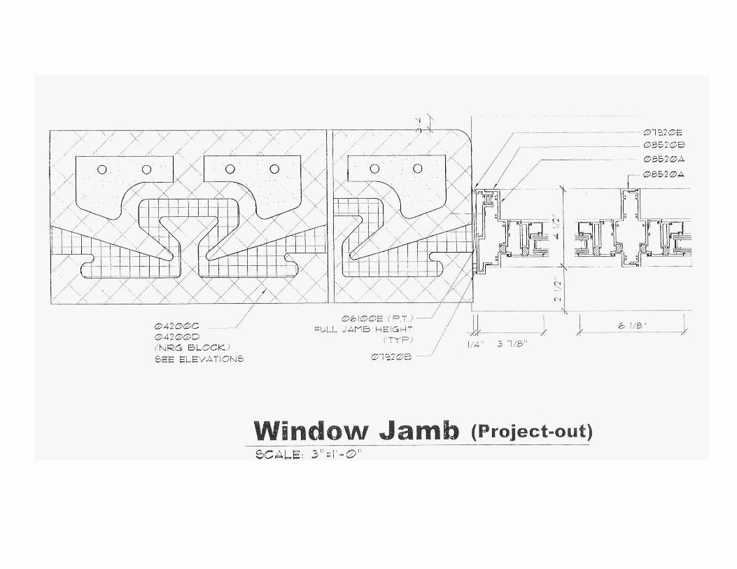
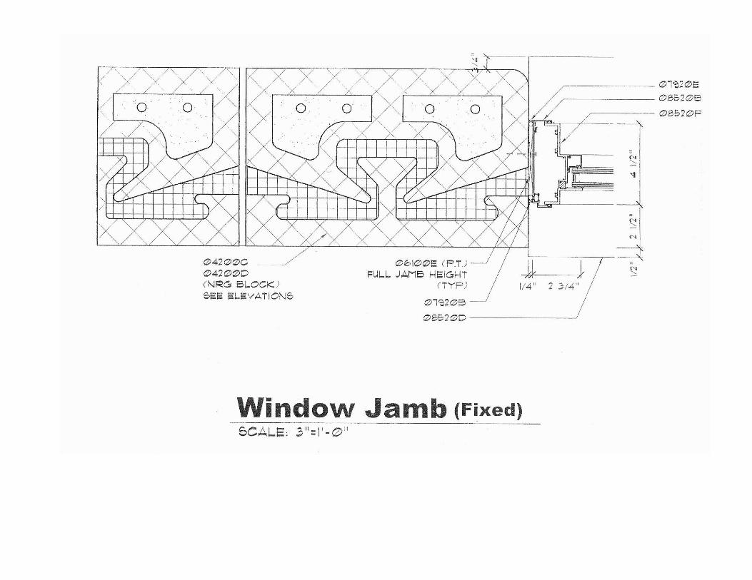
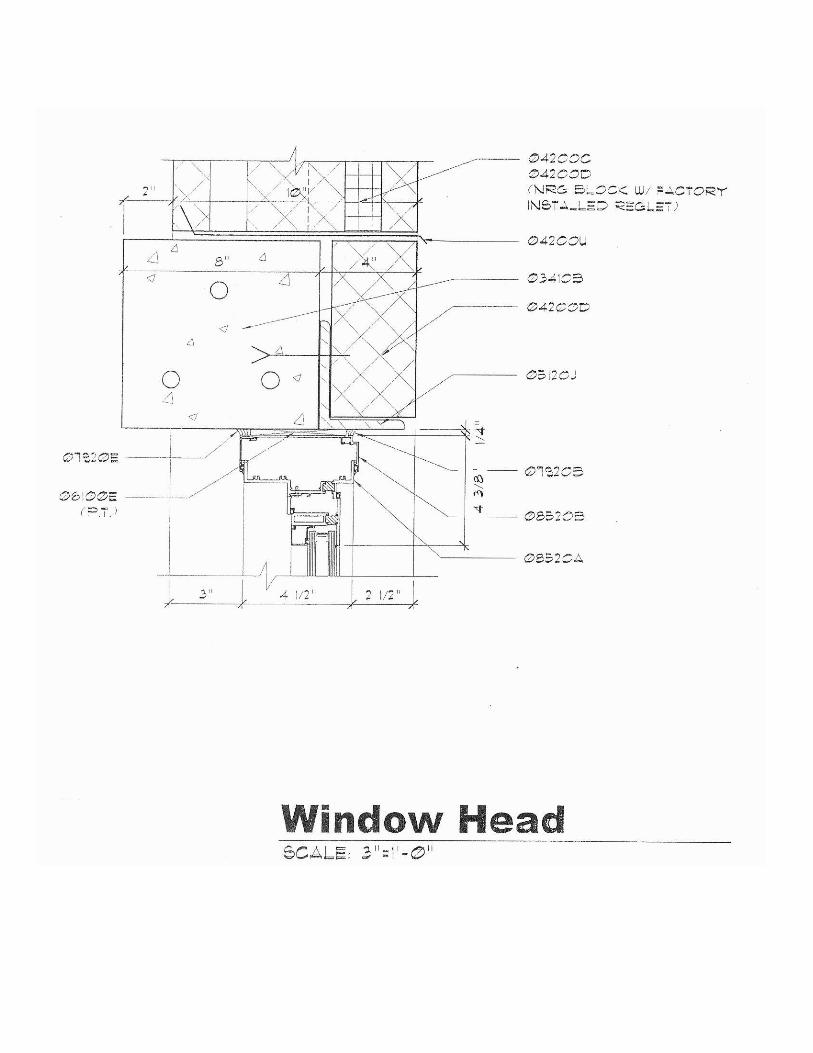
Window jamb, window sill, window
head.


Specifications :NRG Insulated Wall System
Specification: Add, delete, or change any of the following,where local codes, standards, or practices requireamendment.
GeneralConditions Part I: It is important to note that the NRG ICMU(Insulated Concrete Masonry Unit) is designed with an off-centered coreconfiguration. Therefore, the vertical rebar (positioned and set in thepoured foundation)must be matched to the same off-centered designation.(According to specific size units the position of the vertical rebar will vary.)i.e.: 12” ICMU offsetis2.5”
GeneralConditions Part II: List the requirements for mortar, reinforcing,concrete block work and other associated work and details that relate tothis product. If this information is detailed in another section, it should becross-referenced under this heading. The NRG Insulated Wall System islaid similar to any other block, either in a running bond or stacked bond.Units shall be presented to the mason, and the mason shall lay each ICMUwith each“cap” on top of the block and facing the same direction. (Toinsure that the thermal mass of the unit is on the inside, face shell andthumb holes toward the outside exterior of the wall.) Note: This will alsoinsure that the wall is laid with the tightest thermal barrier.
Scope: Interior and exterior walls shall be insulated, web-less, concretemasonry units as shown on the plans/ or indicated on the finish schedule.
Material: All insulated, web-less, concrete masonry units shall be NRGICMU’s, Except corner, half, solid bottom bond beam and sash units. These“special”units shall be conventional units and shall interspersed into theNRG wall construction where needed. Incorporation of conventional CMU’sinto the NRG wall system will have no adverse effect upon thermalperformance of the overall system. NRG ICMU’s are available frommanufacturers licensed by Niagara Regional Group, Ltd. ICMU’s shall bespecified as lightweight, medium weight, or normal weight NRG designunits. All ICMU’s shall conform to ASTM C90StandardSpecificationforload-bearing Type1moisture control units. Additives such as Dry-Block orequivalent shall be specified into the mix design for the ICMU if the unitsare exposed to exterior environmental conditions The NRG ICMU’s areavailable in a large variety of Face textures and colors. However, (Similar toany architectural block) not all manufacturers make all varieties. Therefore,check with local suppliers for availability.
Submittal: Submit color samples for selection from manufactures standardor custom series. Submit product literature, certificates, test reports, full
size sample(s) of each color specified or selected and test reports for colorstability performed under similar conditions of use to ensure againstfading. A sample panel of no less than 4’x4’maybe constructed of units ofeach color and size to be used in the project (these units need not be NRGICMU’s).
Project Site Delivery: NRG ICMU’s shall be wrapped and delivered onwooden pallets. Delivered pallets shall be set on level ground and singlestacked. Glazed units shall be kept dry while stored by means of awaterproof covering, e.g. tarpaulin or plastic wrap.
Face Sizes: Modular 8”x 16”
Face MortarJoints: 3\8” exposed.
Hourly Fire Rating: Define fire rating required as 1, 2, 3or 4 hours(Depth of wall specified must increase as hour ratings increase).
Shapes: Shapes not available in the NRG design shall be substituted forusing conventional hollow core CMU’s matching the same finish and colorof the NRG units.
Scoring: Scoring of the faces hall be accomplished through the moldingprocess, or by cutting 3/8”wide x 1/4”deep grooves into the face of theICMU’s or CMU’s. These grooves shall be pointed and tooled using thesame mortar as used to lay the units. Face joints shall be 3\8”wide and theblock joints on the sides, top and bottom shall be3\8” wide, (thereby givingthe visual effect of 8”x 8” squares)
Miscellaneous Tools and Products Required by Masons: Contractor shallinclude products such as mortar, reinforcing, ties, anchors, and othermasonry attachments as may be required to properly finish the project.Striking or jointing tools , rags, and masonry cleaners shall also berequired.
Lighting: Adequate lighting shall be provided for mason contractor’s work.
Base Course: Base course shall be properly aligned on the floor slab, orfooter.
Cove Base: Cove base shall be tight to the slab if thin floor tiles(vinyl) are to be installed. For thicker flooring material cove basecourse shall be raised to desired height.
Cutting: All cuts for bonding, boxes, holes, etc., shall be madeusing a motor driven masonry saw using either an abrasive or

diamond blade. Note: the NRG unit should not be cut in half.
Workmanship: ICMU’s shall be laid with the faces level, plumb , and true toa line strung horizontally at the face. Units shall have uniform jointdimensions 1/4”both horizontal and vertical. Joints shall be tooled, straightand uniform neatly after they are finger hard. Cut pieces shall be sized andplaced appropriately to maintain consistency and bond. Masonryconstruction shall be completed using procedures and workmanshipconsistent with the best masonry practices.
Scored Face Glazed Units: Head and bed joints shall be raked back¼”after they have hardened, the scored unit shall be tuck pointedand joints raked out.
Reinforcing: Horizontal and other reinforcing shall be installedin locations designated.
Control Joints: Control joints shall be installed in the locationsdesignated in design plans.
Weeps and Vents: The bottom 2”of the vertical joints shall be left open inevery other block unit in the first course above grade. Such open jointsshall also be left open above flashing, beam units, and filled block areasthat act as water stops.
Coping: As shown in details/ Or specified.
Cleaning: Walls shall be kept clean during installation using brush orrags, and a clean damp cloth. Excess mortar clumps or smears shallnot be allowed to harden onto surfaces. Green mortar to be removedwith a dry cloth.
Final Clean down: The complete wall shall be cleaned with a detergentcleaner strictly following the cleaner manufacturers instructions includingthorough rinsing. No acids or abrasives shall be used on the glazedsurface. (Masonry cleaners such as VANATROL and DEOX have been usedsuccessfully).
Other Recommendations:

*All lighting should be placed a reasonable distancefrom wall for even illumination.
*When center scored units are used, the finished wall will be much neaterto lay if stack bond is used. The use of scored units which have bondingpatterns that do not require continuous vertical joints can be installedfaster and more economically.
*Exterior mortar joints should be raked back a minimum of ¼”and tuckpointed with an approved water resistant grout. A typical exterior tuckpointing grout is “LATICRETE1776Grout Admix Plus” used full strengthinstead of mixing water. (“LATAPOXY SP100”may be used for interiorchemical resistant installation).