Engineer Equipment Instruction Web viewENGINEER EQUIPMENT INSTRUCTION COMPANY. ... is a form of...
72
UNITED STATES MARINE CORPS ENGINEER EQUIPMENT INSTRUCTION COMPANY MARINE CORPS DETACHMENT 686 MINNESOTA AVE FORT LEONARD WOOD, MISSOURI 65473-5850 LESSON PLAN CONSTRUCTION MANAGEMENT EEO/EEC-B09 WARRANT OFFICER/CHIEF COURSE A16ACN1/A1613E1 REVISED 01/09/2012 1
Transcript of Engineer Equipment Instruction Web viewENGINEER EQUIPMENT INSTRUCTION COMPANY. ... is a form of...

UNITED STATES MARINE CORPSENGINEER EQUIPMENT INSTRUCTION COMPANY
MARINE CORPS DETACHMENT686 MINNESOTA AVE
FORT LEONARD WOOD, MISSOURI 65473-5850
LESSON PLANCONSTRUCTION MANAGEMENT
EEO/EEC-B09
WARRANT OFFICER/CHIEF COURSE
A16ACN1/A1613E1
REVISED 01/09/2012
APPROVED BY _________________________ DATE_______________
1
(ON SLIDE #1)
INTRODUCTION (10 MIN)
1. GAIN ATTENTION: The ability to manage and supervise a construction project from the start of the project to completion requires in depth planning and strategic organization of all personnel, resources, equipment, and time. Without the knowledge of how to properly plan and organization a construction project, projects can take longer, cost more, and reduce moral. ________________________________________________________________________________________________________________________________________________________________________________________________
(ON SLIDE #2)
2. OVERVIEW: Good morning/afternoon class, my name is ________________. The purpose of this lesson is to provide you with the knowledge to plan and supervise the different activities, resources, personnel, equipment, and time required to successfully complete a construction project.
(ON SLIDE #3)
3. LEARNING OBJECTIVE(S):
a. Terminal Learning Objective:
(1) Provided a horizontal construction project, a construction site, engineer equipment, resources, and references, manage/supervise horizontal construction to meet specifications and milestones per the project specifications and the references. (1310-XENG-2001/1349-XENG-2001)
(2) Provided a mission, a complete project/operation schedule and references, validate project/operation schedule to confirm that the required engineer resources and personnel are identified, the timeline conforms to mission specification, and
2
INSTRUCTOR NOTEIntroduce the learning objectives.
INSTRUCTOR NOTEHave students read learning objectives to themselves.
the graphic depiction of the schedule is accurate. (1310-XENG-2003/1349-XENG-2003)
b. Enabling Learning Objective:
(1) Without the aid of references, identify the Critical Path Method (CPM) per the FM 5-412. (1310-XENG-2001a/1349-XENG-2001a)
(2) Without the aid of references, identify the two types of planning per the FM 5-412. (1310-XENG-2001b/1349-XENG-2001b)
(3) Without the aid of references, identify job directives per the FM 5-412. (1310-XENG-2001c/1349-XENG-2001c)
(4) Without the aid of references, develop a activites list per the FM 5-412. (1310-XENG-2001d/1349-XENG-2001d)
(5) Without the aid of references, identify the four planning diagrams per the FM 5-412. (1310-XENG-2001e/1349-XENG-2001e)
(6) Given project specifications, and without the aid of references, develop an activity on the node diagram per the FM 5-412. (1310-XENG-2001f/1349-XENG-2001f)
(7) Given construction plans, and without the aid of references, implement the construction plan per the FM 5-412. (1310-XENG-2001g/1349-XENG-2001g)
(8) Given a mission, and with the aid of references, review the mission per the references. (1310-XENG-2003a/1349-XENG-2003a)
(9) Given a mission, computer, projector, and with the aid of references, brief the mission per the references. (1310-XENG-2003b/1349-XENG-2003b)
(10) Given a mission, and with the aid of references, ensure the schedule remains updated throughout the duration of the project/operation per the references. (1310-XENG-2003c/1349-XENG-2003c)
(ON SLIDE #4)
3
4. METHOD/MEDIA: This lesson will be presented by lecture, demonstration, and practical application. I will be aided by computer slides, and the dry erase board.
(ON SLIDE #5)
5. EVALUATION: A closed book written/performance examination, and student brief covering the material in this lesson, will be administered at the end of this period of instruction.
(ON SLIDE #6)
6. SAFETY/CEASE TRAINING (CT) BRIEF: There are no safety / cease training concerns for this period of instruction.
(ON SLIDE #7)
TRANSITION: Are there any questions over what is going to be taught, how it will be taught, or how you the student will be evaluated? Let’s start by discussing the Critical Path Method or CPM.________________________________________________________________________________________________________________________________________________________________________________________________
BODY (83 HOURS 45 MIN)
(ON SLIDE #8)
1. CRITICAL PATH METHOD: (1 HR 30 MIN)
In the early 1960's the Critical Path Method (CPM) was developed as a project planning tool.
a. The Critical Path Method (CPM) is a form of analysis that is used for planning, scheduling, and controlling construction activities for a project from start to finish.
4
INSTRUCTOR NOTEExplain Instructional Rating Forms and Safety Questionnaire to students.
INSTRUCTOR NOTEEnsure to explain Crane Shed fire and inclement weather procedures.
(1) The use of the CPM makes it easier to plan, schedule, and manage the sequence of work activities to complete a project on time.
(2) The CPM requires a formal, detailed listing of all work related activities that make up the whole project.This requires you to visualize the project from start to finish, so you can estimate the amount of time and the resources required to complete each project activity.
(ON SLIDE #9)
(3) The CPM is also known by a few other general phrases. Regardless of which phrase is used, they represent the Critical Path Method.
(a) Construction Management.
(b) Project Planning and Scheduling.
(c) Critical Path Analysis.
(ON SLIDE #10)
`b. Using the CPM for Planning: In military construction, the use of the CPM begins with planning. Planning is divided into two distinct stages:
(ON SLIDE #11)
(1) Preliminary Planning: Gives the engineer a quick overall picture of the assigned project and the capacity of the constructing unit to accomplish it. It serves as a guide to the detailed planning which follows. Preliminary planning includes:
(a) Project site reconnaissance.
(b) Preliminary material estimates.
(c) Preliminary equipment estimations.
(d) Procurement of critical items.
(ON SLIDE #12)
(2) Detailed Planning: Develops an accurate estimate of the work activities, materials, man-hours, and equipment required
5

to construct project from start to finish. A detailed plan includes:
(a) Review of all drawings and project specifications.
(b) Detailed estimating of materials, labor and equipment.
(c) Scheduling work activities.
(d) Procurement of required materials.
(e) The detailed plan will be submitted in the form of a Gantt Chart, Pert Chart, Activity-on-the Arrow logic diagram, or as a Activity-on-the-Node logic diagram.
(ON SLIDE #13)
c. Job Directives: The planning process starts with the receipt of a job directive. The job directive (work request) is the authority and tasking of a unit to perform the construction of the project and draw needed materials to complete the project assigned.
(1) Job directives vary in both form and content, and may be issued in one of two ways:
(a) Verbally for simple projects.
(b) Written for more complex projects.
(ON SLIDE #14)
d. The job directive may be in any one of three stages of detail:
(1) It may contain detailed plans and specifications. The more stable the conditions are, the more detailed the directive becomes.
(2) It may simply refer to standard drawings and procedures already published in technical manuals, directives, or automated software programs previously issued from higher headquarters.
(3) It may require the unit to prepare plans and specifications to be approved by the issuing headquarters.
6

(ON SLIDE #15)
e. Regardless of the form the job directive takes, or the amount of detail it provides, the job directive should contain the following information:
(1) Mission. The exact assignment with all necessary and available details.
(2) Location. This may be a definite location, or the directive may require the constructing unit to select a site in a general area.
(3) Time. The starting time and/or required completion dates.
(4) Manpower. Any additional manpower that may be available to the constructing unit.
(ON SLIDE #16)
(5) Equipment. Any additional equipment that may be available the constructing unit, with any special conditions particular to its use.
(6) Materials. Source of and authority for requesting materials, criticality, and lead time for procurement and delivery.
(7) Priorities. A single priority for the entire project or separate priorities for various portions or stages of a project.
(8) Reports. Any reports required by higher headquarters.
(9) Special Instructions. Any additional information concerning the job to include; coordination with the using unit, and unusual problems peculiar to project.
(ON SLIDE #17)
TRANSITION: So far we have covered the critical path method. Are there any questions?
OPPORTUNITY FOR QUESTIONS:
1. QUESTIONS FROM THE CLASS
7

2. QUESTIONS TO THE CLASS:
Q. In what two forms may a job directive be issued?
A. Verbally or in writing
Q. In military construction, the planning process is divided into what two stages?
A. Preliminary planning and detailed planning
(BREAK – 10 Min)
TRANSITION: We’ve just discussed the critical path method. Now, let’s look at how to plan and anticipate activities involved in a construction project, organizing those activities, and deciding on a planning tool to use. ________________________________________________________________________________________________________________________________________________________________________________________________
(ON SLIDE #18)
2. ACTIVITY LISTS: (2 Hrs)
An activities (task) list is a complete listing of all the work activities that must be performed from start to finish to complete the project. This is the initial step in the CPM.
a. An activity list can be as brief, or as detailed as need be for the assigned project. The guiding factor which helps you determine how brief or detailed the activities list will be, is the size and complexity of the project.
b. The project must be constructed mentally, and on paper to determine the actual project activities and their relationships to each other. This is the most difficult part of the planning process. You must be able to “think logically” in terms of what activities must be performed, and the order in which the activities must be completed.
c. The first step is to break the project down into each of its actual work activities. This is done by studying site reconnaissance notes, construction plans, project specifications, and “brainstorming” with the Project Officer, Engineer Equipment Chief, and Combat Engineer Chief.
8

d. Let’s put this process of “logical thinking” to work using the project scenario of constructing a one lane gravel road that is 1500 feet long, leading to a concrete storage pad that is 32’-0” x 32’-0” in size.
(1) The first step is to make a mental picture of what
activities must be performed to construct this project from start to finish, and then create a rough activity list with the help of everyone’s input.
(ON SLIDE #19)Rough Activities
“Topo” project site Establish road gradesLay gravel Set road alignmentsOrder gravel Place concrete formsClear roadway Clear pad sitePrefabricate forms Create project drawingsLayout pad batterboards Excavate pad footingsPour concrete Cure concreteCheck pad elevation’s Check Road gradesRemove forms Perform “As-built”
(2) Once the rough activities list has been completed, you can begin to put each activity into a logical sequence in which they are to be performed.
(ON SLIDE #20)
e. After you have determined the activities to be performed for the project, you must put each task in a logical sequence in which they will actually be constructed. Your finished activity list will be broken down into three separate columns showing the following information:
(1) Activity Number Column: Each and every work activity will be assigned an activity number. It is best to use numeric values in increments of 5 or 10, as this allows you to insert additional tasks later as the need arises. Never use the same number twice, as this leads to confusion.
(2) Activity Column: This is a complete listing of all the required tasks which must be performed to complete the project from start to finish.
(3) "Immediately Proceeded By" (IPB) Column: This column is a listing of the activity number(s) for the activities that
9

“immediately” proceed the one that is being listed. In other words, what activity(s) must be completed before another one can begin? Starting activities will always have the word “None” listed here.
(ON SLIDE #21)
f. Types of Activities: Ask yourself the following questions for each work activity of the project to develop the finished activities list:
(1) Which activities start at the beginning of the project? (Starting Activities)
(2) Which activities must be finished before another activity can begin? (Preceding Activities)
(3) Which activities can either start or finish at the same time as another activity? (Concurring Activities)
(4) Which activities cannot begin until another activity is finished? (Succeeding Activities)
(5) Which activities may start when a portion of another activity is complete? (Lagging Activities)
(ON SLIDE #22)
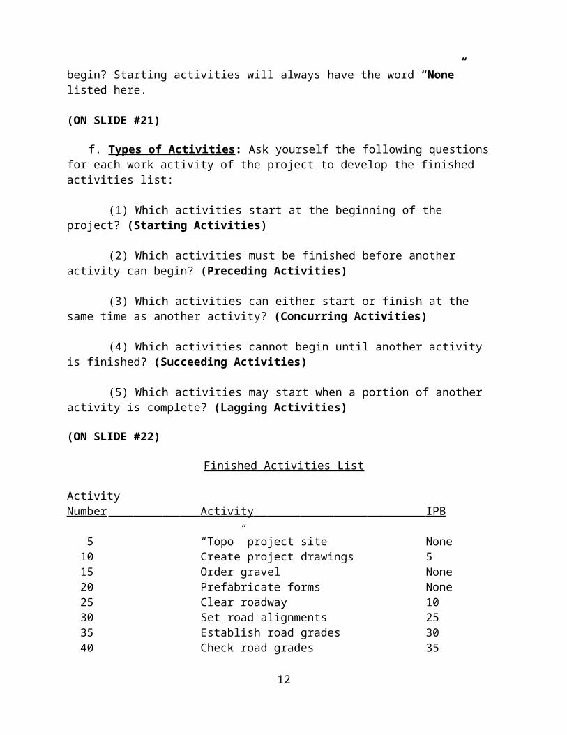
Finished Activities List
ActivityNumber Activity IPB
5 “Topo” project site None 10 Create project drawings 5 15 Order gravel None 20 Prefabricate forms None 25 Clear roadway 10 30 Set road alignments 25 35 Establish road grades 30 40 Check road grades 35 45 Lay gravel 15,40 50 Clear pad site 10 55 Layout pad batterboards 50 60 Excavate pad footings 55 65 Check pad elevation’s 60 70 Place concrete forms 20,65
10

75 Pour concrete 70 80 Cure concrete 75 85 Remove forms 80 90 Perform “As-built” 45,85
g. It is important to remember that an activity list can be as brief or as detailed as necessary. The amount of detail that is required is generally dictated by the size and complexity of the project itself.
(ON SLIDE #23)
TRANSITION: We have just covered brainstorming the activities list then sequencing your list in a logical order. Are there any questions?
OPPORTUNITY FOR QUESTIONS:
1. QUESTIONS FROM THE CLASS
2. QUESTIONS TO THE CLASS:
Q. What is the process called to develop your activities list?
A. Brainstorming
Q. What are the five types of activities that are kept in mind when developing a finished activiy list?
A. Starting, proceeding, succeeding, concurring, and lagging activities
(BREAK – 10 Min)
TRANSITION: After developing your activities list in a logical sequence based on your construction requirements, we will now learn how to schedule your timeline for activities from the durations calculated in your production estimations. ________________________________________________________________________________________________________________________________________________________________________________________________
(ON SLIDE #24) 3. PLANNING DIAGRAMS: (2 Hrs)
11
The most important feature of the CPM is the planning diagram. The planning diagram graphically shows the projects various work activities. They provide a visual blueprint of the work activities that must be performed during the construction of a project. There are four types of diagrams that can be created.
(ON SLIDE #25)
a. Gantt Charts: One method of graphically planning construction projects is through the development of a Gantt Chart, also referred to as a bar chart.
(1) Gantt charts are time oriented planning diagrams used primarily for small projects, and scheduling inspections.
(2) Work activities on Gantt charts are shown graphically on a calendar time scale.
(3) Each bar represents the start and finish date, with the length of the bar showing the activities duration.
(4) The bars show an activities duration in its entirety, regardless of its dependency on other activities.
(5) Gantt charts are effortless to construct.
(6) They are brief in format.
(ON SLIDE #26)
12

(ON SLIDE #27)
(ON SLIDE #28)
(7) The major draw back of Gantt Charts is that you must have a detailed knowledge of the project and the construction techniques used to complete the tasks to interpret the progress of construction work. Other disadvantages of the Gantt Chart are:
(a) It does not give you the ability to visualize the exact progress of the project.
(b) Anticipate delays or problems soon enough to correct them.
(c) It does not show the detailed sequence of activities of the project.
(d) It does not show which activities are critical to the successful, and timely completion of the project.
(e) It does not show the precise effect of a delay or failure to complete an activity on time.
(ON SLIDE #29)
b. Pert Chart: The Program Evaluation and Review Technique (PERT) chart addresses probability.
13

(1) Pert charts are event oriented.
(2) This type of diagram is used primarily in research and development projects.
(ON SLIDE #30)
Clear r oadway
5 2d4/ 15/ 97 4/ 16/ 97
Clear padsit e
10 1d4/ 15/ 97 4/ 15/ 97
Cr eat epr ojectdr awings
2 2d4/ 11/ 97 4/ 14/ 97
Topopr ojectsit e
1 2d4/ 9/ 97 4/ 10/ 97
(ON SLIDE #31)
c. Activity-On-The-Arrow (AOA)or CPM: This format is more complex in its creation and is “activity” oriented.
(1) Has a tendency to lead to confusion when trying to interpret it.
(2) This format is the least desirable due to these factors.
(ON SLIDE #32)
14

(ON SLIDE #33)
d. Activity-On-The-Node (AON): Commonly referred to as the CPM, The use of this type of format will eliminate confusion, and allows you to adjust to many of the problems that might arise during the construction phase of the project. It is “activity” oriented.
(1) The AON format is the primary planning diagram that is used for project planning for military construction.
(2) It is especially useful for planning large construction projects.
(ON SLIDE #34)
(3) This diagramming method is used effectively for the Critical Path Method in planning the following areas:
(a) Construction.
(b) Maintenance.
(c) Project Design.
(d) Military Combat Tasks.
(e) Logistics.
(ON SLIDE #35)
(4) The AON format overcomes the disadvantages of using the Gantt Chart by showing an accurate, timely, and easily understood picture of the project. Other advantages of using this type of diagram are:
(a) Reduces the risk of overlooking essential construction tasks.
(b) Provides a blueprint for long-range planning of the project.
(c) Shows the interrelationship between work activities.
(d) Focuses attention on critical work activities.
15

(e) Allows you to make timely decisions to correct problems if complications should arise.
(f) Allows you to manage manpower, material, and equipment resources more effectively.
(ON SLIDE #36)
(5) Though the AON is a powerful tool for Officers and Staff NCO’s to use for project planning purposes, it does have its disadvantages.
(a) The AON format does not solve engineering problems that may be encountered.
(b) It does not make planning decisions for you.
(c) It does not provide anything substantial to the actual construction of the project itself.
(ON SLIDE #37)
(ON SLIDE #38)
16
AON

(6) ACTIVITY-ON-THE-NODE DIAGRAM ELEMENTS: Before you begin creating your planning diagram, you must have an understanding of what each element of the diagram represents. We will concentrate our emphasis on the Activity-on-the-Node diagram format. There are four basic elements of a AON diagram:
(a) Activity Nodes: An activity node is a simple rectangle or parallelogram that represents each activity from the finished activities list. Each node is connected by precedence arrows, and contains certain information to enable you to manage that work activities completion:
(ON SLIDE #39)
1 Activity Number: A number that identifies a specific work activity. These numbers are never duplicated, as it will lead to confusion. These numbers are taken from the finished activities list activity number column.
2 Duration: A number which is represented in hours, days, weeks, or months. This number is the calculated amount of time that is required to complete that activity, and is extracted from production estimate sheets, activity estimate sheets, or from published equipment and man-hour tables.
3 Resources: Shows the required resource(s) needed to complete that activity (manpower, materials, and/or equipment). This is normally left blank when there is more than one required resource for the activity.
4 Early Start (ES): A number which is represented in hours, days, weeks, or months. This is the earliest time that an activity can logically start without affecting succeeding
17

activities. This number represents the end of a working hour, day, week, or month.
5 Early Finish (EF): A number which is represented in hours, days, weeks, or months. This is the earliest time that an activity can logically finish without affecting succeeding activities. This number represents the end of a working hour, day, week, or month.
6 Late Start: A number which is represented in hours, days, weeks, or months. This is the latest time that an activity can start without delaying the entire project. This number represents the end of a working hour, day, week, or month.
7 Late Finish: A number which is represented in hours, days, weeks, or months. This is the latest time that an activity can finish without delaying the entire project. This number represents the end of a working hour, day, week, or month.
(ON SLIDE #40)
e. Precedence Arrows: Also referred to as “logic” arrows, show the order sequence, and the interrelationship between work activities. They are drawn to show how each every activity is connected, and help to identify the “critical path” of the project. These logic arrows are never drawn backwards, but can cross each other.
(ON SLIDE #41)
f. Start Node: This type of node is shown as a circle, and has no duration time associated with it. All starting activities are tied in to this node at the beginning of the diagram with precedence arrows.
18

g. Finish Node: This type of node is shown as a circle, and has the total project duration time associated with it. All finishing activities are tied in to this node at the end of the diagram with precedence arrows.
(ON SLIDE #42)
TRANSITION: We have just covered some of the most common types of logic diagrams used in military construction. Are there any questions?
OPPORTUNITY FOR QUESTIONS:
1. QUESTIONS FROM THE CLASS
2. QUESTIONS TO THE CLASS:
Q. What type of diagram is event oriented?
A. Pert Chart
Q. What type of diagram is time oriented?
A. Gantt Chart
Q. What type of diagram(s) is/are activity oriented?
A. Activity on the Arrow and Activity on the Node
(BREAK – 10 Min)
TRANSITION: Now that you are familiar with the different types of planning tools available to use, we will focus our effort on the logic diagram that is most widely used in military construction: the Activity on the Node. The AON logic diagram is predominantly used by the Army Corps of Engineers for a vast
19

majority of their construction projects and is more widely recognized by engineers across all branches of the military. ________________________________________________________________________________________________________________________________________________________________________________________________
(ON SLIDE #43)
4. ACTIVITY-ON-THE-NODE DIAGRAM CREATION: (2 Hrs 15 Min)
After you have the necessary activity relationships identified in the finished activities list, you must now apply them to the creation of a planning diagram, also referred to as a “logic” diagram. This is done by working left to right on a piece of blank scratch paper.
a. Start off with drawing the Start Node, this is the "Jumping Off" point for all starting activities, and the rest of your diagram.
(ON SLIDE #44)
b. The activity nodes are now drawn in their proper logical sequence using the activities listed in the IPB column of the finished activities list. Use the following logic rules to create the AON logic diagram:
(1) What activity(s) start at the beginning of the project? (Start) These activity nodes will always have "None" listed in the IPB column.
(2) What activity(s) must be finished before the start of another? (Precedence)
(3) What activity(s) may either start or finish at the same time as another? (Concurrence)
(4) What activity(s) cannot begin until another is finished? (Succession)
(5) Which activities may start when a portion of another activity is complete? (Lag)
c. The activity nodes are now linked together with precedence arrows. When activity nodes are linked together with precedence arrows, the diagram will show how all activities are interrelated, and what their dependence is on the other
20

activities. All finishing activities for the project must end at the Finish Node.
d. If there is any mistakes in your logic, you will catch them here during the creation of the logic diagram.
(ON SLIDE #45)
INTERIM TRANSITION: We have covered the development of a logic diagram? Are there any questions or comments? Now, observe the instructor as he/she demonstrates drawing a logic diagram using the start, finish, and activity nodes.________________________________________________________________________________________________________________________________________________________________________________________________
DEMONSTRATION(1). (20 MIN) Using the dry erase board and/or overhead projector and overlay, demonstrate how to develop the logic diagram using problem number one of Worksheet 1 on page 22 of the student outline. STUDENT ROLE: Observe the instructor, follow along by copying the logic diagram the instructor draws, and ask questions.
INSTRUCTOR(S) ROLE: List the activities and the IPB’s:
Activity IPB 5 None10 None15 None20 525 5,10,1530 1535 3040 30
then place the activity numbers in a logic diagram using the IPB as the basis.
21
INSTRUCTOR NOTEIntroduce the following demonstration (1).
5
10
20
25

1. Safety Brief: Classroom instruction, there are no safety concerns for this period of instruction.2. Supervision & Guidance: Students will be encouraged to ask questions. 3. Debrief: Are there any questions or comments concerning developing a logic diagram? The logic diagram will allow you to plan and schedule a construction project from start to finish as well as allowing for any changes or manipulation of the original plan. The logic diagram is widely utilized by engineers in all branches of military service.
INTERIM TRANSITION: Are there any questions? Now, practice developing some logic diagrams by completing problems 2 – 5 on worksheet 1.________________________________________________________________________________________________________________________________________________________________________________________________
PRACTICAL APPLICATION(1): (30 Min) Have the students complete Worksheet 1 problems 2 – 5 on page 22 of the student handout.
PRACTICE: Complete problems 2 – 5 using the start and finish nodes, activity nodes (for this exercise, only the activity numbers will be required in the activity node), and precedence arrows depicting the “Immediately Preceded By” activities.
PROVIDE-HELP: Walk around the classroom and aid the students by answering questions and providing guidance.
SAFETY BRIEF: No safety concerns with this class.
SUPERVISION & GUIDANCE: Be sure to follow the step by step directions covered in your student outline along with the instructor’s supervision. Once all students have completed the
22
15 30
35
40
S F
INSTRUCTOR NOTEIntroduce the following practical application (1).

exercise or the time limit has expired, ensure to review the prolems and answer questions.
DEBRIEF: Now that you have a general understanding of developing a logic diagram, let’s look at incorporating resource estimates and time estimates into the logic diagram.
(ON SLIDE #46)
INTERIM TRANSITION: We have just completed the practical application for the beginning stages of developing a logic diagram? Are there any questions.
OPPORTUNITY FOR QUESTIONS:
1. QUESTIONS FROM THE CLASS________________________________________________________________________________________________________________________________________________________________________________________________
(BREAK – 10 Min)
WORKSHEET 1
Using one sheet of paper for each practice problem, draw a rough logic diagram that logically shows the interrelationships of each of the project activities. You will have 60 minutes to work on these practice problems.
Activity IPB
1. 5 None10 None15 None20 525 5,10,1530 1535 3040 30
2. 5 None10 None15 520 525 1030 10,20
23
S F
S F
5
1
1
2
2
3
3
4
5
1
2
1
3
3
4
INSTRUCTOR NOTEThis is the Answer key for Worksheet 1.

35 1540 15
3. 5 None10 515 520 10,1525 2030 2035 25,30
4. 5 None10 None15 1020 525 None30 1035 2540 30,3545 30,3550 5,4555 30,35
5. 5 None10 None15 None20 1025 1530 5,2035 2540 30,35
INTERIM TRANSITION: Are there any questions, if not lets talk about resource estimates.
(ON SLIDE #47)
e. RESOURCE ESTIMATES: The next step in the planning process is to estimate the required resources for each and every activity within the project.
(1) Estimated resources are materials, personnel and equipment quantities, and man-hours and equipment hours. These are all of the resources that are required to complete each respective activity within the project. There are two types of estimates:
(ON SLIDE #48)
(a) Material Estimates.
(ON SLIDE #49)
24
S F
S F
S F
2
5
1
1
22
3
3
5
1
2
2
1
3000
3
4
4
5
5
5
1
1 2
2
3
3
4

(b) Equipment/Manpower Estimates
(2) Duration’s are calculated based on the amount of material that must be handled, or the amount of effort that must be put in using manpower. It is the estimated amount of time that it will take to complete an activity from start to finish. Duration’s are represented in hours, days, weeks, or months. There are a few guidelines that will aid you during the calculation of activity duration’s.
(a) Increasing a crew size or the numbers of equipment will reduce the duration time of an activity.
(b) Decreasing the crew size or the numbers of equipment will increase the duration time of an activity.
(c) Increasing the length of the work day will reduce the duration time of an activity.
(d) Decreasing the length of the work day will increase the duration time of an activity.
(e) Working on the weekend will reduce the duration time of the project as a whole.
(3) After the resources and duration’s for each activity have been determined, annotate them on the finished activities list for a quick reference, and label each activities duration on the logic diagram you created previously.
(ON SLIDE #50)
25

26

(ON SLIDE #51)
f. EARLY/LATE EVENT TIMES: After all duration's have been computed, you are now able to calculate all of the early and late event times for each activity on the logic diagram.
(1) Each early and late event time serves a specific purpose. A description of each type of event time is as follows:
(a) Early Start: The earliest time that activity can logically start without delaying follow-on activities.
(b) Early Finish: The earliest time that activity can finishwithout delaying follow-on activities. (Early Start + Duration)
(c) Late Finish: The latest time an activity can
finish without delaying the entire project.
(d) Late Start: The latest time an activity can start without delaying the entire project. (Late Finish - Duration)
(ON SLIDE #52)
ACTIVITIES LIST WITH DURATION'SActivityNumber Activity IPB Duration
5 “Topo” project site None 2 days 10 Create project drawings 5 2 days 15 Order gravel None 6 days 20 Prefabricate forms None 1 day 25 Clear roadway 10 2 days 30 Set road alignments 25 1 day
27

35 Establish road grades 30 1 day 40 Check road grades 35 2 days 45 Lay gravel 15,40 2 days 50 Clear pad site 10 1 day 55 Layout pad batterboards 50 1 day 60 Excavate pad footings 55 2 days 65 Check pad elevation’s 60 1 day 70 Place concrete forms 20,65 1 day 75 Pour concrete 70 1 day 80 Cure concrete 75 6 days 85 Remove forms 80 1 day 90 Perform “As-built” 45,85 2 days
(2) Begin computing early start times by placing a zero (0) in the upper-left corner of the activity nodes that are starting activities. Starting activities will always have “None” in the IPB column, and an early start time of zero.
(3) Compute the early finish time for each of the starting activities, and annotate the time in the upper-right corner of the node. (Early Start + Duration)
(4) The early finish that you just computed, now becomes the early start for the next activity(s), and is annotated in the upper left-hand corner of that next activity(s). If two or more proceeding activities close on a single activity, use the greater early finish time for the next activity nodes early start.
(5) Repeat the process for the rest of the activity nodes in the logic diagram. This process is referred to as the "Forward Pass".
(6) After you have computed the early finish for the last activity node, this becomes the total duration for the project, and is annotated on the finish node. If more than 1 activity closes on the finish node at the same time, you must use the largest early finish value as the total duration.
(7) Now you must compute the late finish and late start times for each activity. This process is referred to as the "Backward Pass".
(8) Annotate the total duration as the late finish for each of the activity nodes that closed on the finish node. These times are placed in the lower-right hand corner of the activity node.
(9) Next, compute the late start times for each respective
28

activity node, and annotate the time in the lower-left corner of the activity node. (Late Finish - Duration)
(10) The late start that you just computed, now becomes the late finish for the next activity. If two or more proceeding activities close on a single activity use the smaller late start time for that next activity nodes late finish.
(11) Repeat this process for the rest of the activity nodes until you are at the beginning of the CPM diagram again.
(12) After you have computed the late start for the last activity nodes, this completes the backward pass.
(ON SLIDE #53)
(13) Now by simple observation, you can identify the Critical Activities and the projects Critical Path. Use the following guidelines to determine which activities are critical.
(a) The early start time for a particular activity is the same as the late start time.
(b) The early finish time for a particular activity is the same as the late finish time.
(14) When critical activities are linked together, they form the critical path of the project. The logic arrows linking critical activities can be made with a thicker line width, highlighted in color, or shown with two vertical lines drawn on the logic arrow identifying it as part of the critical path. This critical path must also begin at the start node and end on the finish node.
(15) There will always be at least one or more critical paths. All critical paths must be continuous. Any critical path that does not start at the start node and end at the finish node indicates a logic mistake, or a simple mistake that was made during the calculation of the forward or backward pass.Note: If a critical activity is delayed by any amount of time, the entire project completion will be delayed by that same amount of time.
TRANSITION: We have just covered determining start and finish times for a logic diagram. Are there any questions or comments? Now, observe the instructor as he/she demonstrates calculating
29

the start and finish times on worksheet 3 using the information from the activities list on page xxxx.________________________________________________________________________________________________________________________________________________________________________________________________
(ON SLIDE #54)
DEMONSTRATION(2). (20 MIN) Ensure each student has one copy of worksheet 2, 3 and 4 (Early/Late Event Times) in their student handout. Worksheet 2 is the demonstration and worksheet 3 and 4 are the practical application. Using the dry erase board and/or overhead projector and overlay, demonstrate how to complete the early start schedule as shown on Worksheet #4. Ensure to identify the critical path for the student. STUDENT ROLE: Observe the instructor, follow along by copying the early start schedule the instructor illustrates on the dry erase board or overhead projector, and ask questions. INSTRUCTOR(S) ROLE: Using the activities list on page 25 of the Detailed Outline, demonatrate the forward pass and backward pass in order to determine the early and late start and finish times.
1. Safety Brief: Classroom instruction, there are no safety concerns for this period of instruction.2. Supervision & Guidance: Students will be encouraged to ask questions. 3. Debrief: Are there any questions or comments concerning how to calculate the early or late start times for a logic diagram? Are there any questions or comments concerning how to calculate the early or late start finish times? The early and late start/finish times are the basis for determining the next step in the logic diagram; the float times.
INTERIM TRANSITION: Are there any questions? Now, practice what you have learned on worksheet 3 by filling in the activity nodes using the forward and backward pass to determine the event times.________________________________________________________________________________________________________________________________________________________________________________________________
30
INSTRUCTOR NOTEIntroduce the following demonstration (2).
INSTRUCTOR NOTEIntroduce the following practical application (2).

(ON SLIDE #55)
PRACTICAL APPLICATION(2): (30 Min) Have the students complete Worksheet 3 and 4. Worksheet 3 and 4 consists of calculating the forward pass and backward pass to determine event times and identify the critical path using the critical path precedence lines. (Worksheet 3 and 4 answer key is located at the end of the detailed outline.
PRACTICE: Have the students complete worksheet 3 and 4 using the following criteria: Calculate the early start and finish times. Calculate the early and late finish times. Calculate the total project time. Identify the critical path using precedence arrows.
PROVIDE-HELP: Walk around the classroom and aid the students by answering questions and providing guidance.
SAFETY BRIEF: No safety concerns with this class.
SUPERVISION & GUIDANCE: Be sure to follow the step by step directions covered in your student outline along with the instructor’s supervision. Once all students have completed the exercise or the time limit has expired, ensure to review the prolems and answer questions.
DEBRIEF: Now you have know how to calculate the event times. These event times will allow you to determine the total project time. Next, we will look at calculating float time for each event in order to determine which events must be completed on time.
(ON SLIDES #56, 57)
INTERIM TRANSITION: We have just completed the practical application for determining event times? Are there any questions. Let’s move on to determining what “float time” is and how to calculate these times.
OPPORTUNITY FOR QUESTIONS:
1. QUESTIONS FROM THE CLASS
2. QUESTION TO THE CLASS
31

Q. What type of resources must be estimated for each activity?
A. Material, personnel, equipment quantities, man hours and equipment hours.
Q. What effect does increasing equipment quantities have on the duration of an Activity?
A. It decreases duration time.Q. What do we call the process use to calculate the early event times for a project?
A. Forward pass.
Q. What do we call the process use to calculate the late event times for a project?
A. Backward pass.
________________________________________________________________________________________________________________________________________________________________________________________________
(BREAK – 10 Min)
(ON SLIDE #58)
g. EARLY START SCHEDULE: An early start schedule, when joined with the logic diagram, graphically shows all of the planning information that is needed to manage the construction of a project. The early start schedule in itself, enables you to schedule and track all required activity resources for each and every day of the project from start to finish. This schedule is instrumental in anticipating and adjusting for any possible delays.
(ON SLIDE #59)
h. Float: Any activity that is not on the Critical Path is a non-critical activity, and will contain float time. Float is any extra time that is available to complete an activity beyond its actual duration without effecting the entire project duration. An example would be having six (6) days available to do four (4) days of work to complete an activity.
32

(1) Total Float (TF): The entire amount of time that an activity can be delayed without delaying the projects estimated completion time. It is computed by the following formula: TF = LS - ES or TF = LF - EF. Both equations will give the same answer.
(2) Interfering Float (IF): The time that is available to delay an activity without delaying the entire projects completion time, but delaying an activity into interfering float will delay the start of one or more non-critical activities later. If more than one activity follows the one being computed for, always use the smallest ES time using the formula: IF = LF - (ES of following activity).
(3) Free Float (FF): Time that is available to delay an activity without delaying the start of any other activity, or the projects completion time. Free float is determined by: FF = TF - IF.
(ON SLIDE #60)
i. All non-critical activities will have total float, but they can have all interfering float, free float, or a combination of the two.
j. Critical activities on the Critical Path will have no float time.
k. This early start schedule will show when all activities are to start and finish on schedule, and list the resources and the numbers that are required for each day of work.
(1) The first step is to list all activity numbers in numerical order. After each activity number, write in parentheses the activity number(s) for the activity(s) that are connected to it with a logic arrow.
(2) The next step is to draw time brackets to represent the early start time and late finish time. The number of blank boxes in between these brackets is equal to the activities duration.Note: Early start times for starting activities will always be day 1. All other early start times will begin on the morning of the following day. This is because the early start times you calculated represent the end of that work day, and a follow on activity, logically, will not start until the morning of the next working day.
33

(3) Once the time brackets have been drawn in, you must schedule the required resources to complete that respective activity. This information is extracted from each activity estimate sheet.
(a) Starting at the start bracket, place the number of each kind of resource inside each box from left to right. Do not exceed the activities duration when labeling its resources.
(b) Along with the resource quantity, an abbreviation identifying the type of resource is also included. Some of the standardized abbreviations are as follows:
1 Squads = SQ
2 5-ton truck = 5T
3 Tram = TR
4 Scraper = SC
5 Dozer = DZ
6 Grader = GD
7 SEE tractor = ST
8 Excavator = EX
9 Survey Crew = S
10 Compactor = CP
11 Draftsman = D
(4) The blank boxes that remain represent the amount of float time that is available for non-critical activities. This float will be either interfering float, free float, or a combination of the two. Remember, critical activities have no float.
(a) Calculate the interfering float for that activity.
(b) Calculate the free float for that activity.
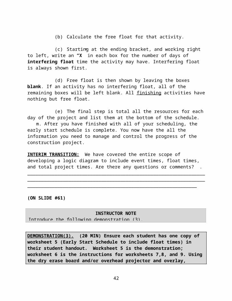
(c) Starting at the ending bracket, and working right to left, write an “X” in each box for the number of days of
34

interfering float time the activity may have. Interfering float is always shown first.
(d) Free float is then shown by leaving the boxes blank. If an activity has no interfering float, all of the remaining boxes will be left blank. All finishing activities have nothing but free float.
(e) The final step is total all the resources for each day of the project and list them at the bottom of the schedule.
m. After you have finished with all of your scheduling, the early start schedule is complete. You now have the all the information you need to manage and control the progress of the construction project.
INTERIM TRANSITION: We have covered the entire scope of developing a logic diagram to include event times, float times, and total project times. Are there any questions or comments? .________________________________________________________________________________________________________________________________________________________________________________________________
(ON SLIDE #61)
DEMONSTRATION(3). (20 MIN) Ensure each student has one copy of worksheet 5 (Early Start Schedule to include float times) in their student handout. Worksheet 5 is the demonstration; worksheet 6 is the instructions for worksheets 7,8, and 9. Using the dry erase board and/or overhead projector and overlay, demonstrate how to complete the logic diagram.Ensure to identify the critical path for the student. STUDENT ROLE: Observe the instructor, follow along by copying the information from the logic diagram that the instructor illustrates on the dry erase board or overhead projector, and ask questions. INSTRUCTOR(S) ROLE: Using the activities list included on worksheet 5, demonatrate the forward pass and backward pass in order to determine the early and late start and finish times, calculate the interfering, free, and total float times, total project times. Once this is complete list the activities, IPB’s, and resources with totals in the activities chart.
35
INSTRUCTOR NOTEIntroduce the following demonstration (3).
1. Safety Brief: Classroom instruction, there are no safety concerns for this period of instruction.2. Supervision & Guidance: Students will be encouraged to ask questions. 3. Debrief: Are there any questions or comments concerning how to develop a complete logic diagram? Are there any questions or comments concerning how to calculate the early or late start finish times? Listing of resources? Totaling resources? A well thought out logic diagram gives an OIC/Chief the ability to have a plan in place sequencing events as they occur in order to facilitate planning in a flexible manner while allowing for changes in the plan and still being able to keep events on schedule.
INTERIM TRANSITION: Are there any questions? Now, practice what you have learned. Worksheet 6 gives the directions for filling out logic diagram worksheets 7,8, 9, 10, 11, and 12. All worksheets must include the forward pass, backward pass, float calculations for activities not on the critical path, resource planning, and resource totals in the chart at the bottom of the worksheet. Upon completion, we will review each worksheet and answer any questions you may have.________________________________________________________________________________________________________________________________________________________________________________________________
(ON SLIDE #62, 63, 64)
PRACTICAL APPLICATION(3): (30 Min) Have the students complete Worksheet 7 through 12 using the directions on worksheet 6. (Answer keys are located at the end of the detailed outline.
PRACTICE: Have the students complete the logic diagram worksheets using the following criteria: Calculate the early start and finish times. Calculate the early and late finish times. Calculate the total project time. Identify the critical path using precedence arrows. Calculate float times and develop the resources list in the chart at the bottom of the page.
PROVIDE-HELP: Walk around the classroom and aid the students by answering questions and providing guidance.
36
INSTRUCTOR NOTEIntroduce the following practical application (3).
SAFETY BRIEF: No safety concerns with this class.
SUPERVISION & GUIDANCE: Be sure to follow the instructor’s directions from the demonstration and material covered in your student outline. Once all students have completed the exercise or the time limit has expired, ensure to review the prolems and answer questions.
DEBRIEF: Now you know how to develop a logic diagram and list resources. This will allow you to begin your project planning and presentation that will conclude your training here at Fort Leonard Wood.
(ON SLIDE #65, 66)
INTERIM TRANSITION: We have just covered developing a logic diagram and using the Critical Path Method to plan, supervise, and coordinate a construction project. Are there any questions?
OPPORTUNITY FOR QUESTIONS:
1. QUESTIONS FROM THE CLASS
2. QUESTIONS TO THE CLASS:
Q. What is float?
A. Any extra time that is available to complete an activity beyond its actual duration without affecting the entire project.
Q. What is interfering float?
A. Time that is available to delay an activity without delaying the projects entire completion time, but may delay the start of one or more non-critical activities.
INTERIM TRANSITION: Are there any questions? Now, practice what you have learned. Worksheet 6 gives the directions for filling out logic diagram worksheets 7,8, 9, 10, 11, and 12. All worksheets must include the forward pass, backward pass, float calculations for activities not on the critical path, resource planning, and resource totals in the chart at the bottom of the worksheet. Upon completion, we will review each worksheet and answer any questions you may have.________________________________________________________________________________________________________________________________________________________________________________________________
37

PRACTICAL APPLICATION(4): (30 Min) Have the students complete Worksheet 7 through 12 using the directions on worksheet 6. (Answer keys are located at the end of the detailed outline.
PRACTICE: Have the students complete the logic diagram worksheets using the following criteria: Calculate the early start and finish times. Calculate the early and late finish times. Calculate the total project time. Identify the critical path using precedence arrows. Calculate float times and develop the resources list in the chart at the bottom of the page.
PROVIDE-HELP: Walk around the classroom and aid the students by answering questions and providing guidance.
SAFETY BRIEF: No safety concerns with this class.
SUPERVISION & GUIDANCE: Be sure to follow the instructor’s directions from the demonstration and material covered in your student outline. Once all students have completed the exercise or the time limit has expired, ensure to review the prolems and answer questions.
DEBRIEF: Now you know how to develop a logic diagram and list resources. This will allow you to begin your project planning and presentation that will conclude your training here at Fort Leonard Wood.
(ON SLIDES #67 through 79)
INTERIM TRANSITION: We have just covered developing a logic diagram and using the Critical Path Method to plan, supervise, and coordinate a construction project. Are there any questions? We will now move into the project brief.________________________________________________________________________________________________________________________________________________________________________________________________
PRACTICAL APPLICATION(5): (73 HRS)Project Planning and Briefing
PRACTICE: Students will estimate and plan a horizontal construction project from start to finish. On the date and time
38
INSTRUCTOR NOTEIntroduce the following practical application (4).

prescribed, students will also brief their plan to a panel of subject matter experts. The panel may include but is not limited to the Company Commander, Company Executive Officer, First Sergeant, Marine Unique SNCOIC, any or all available Marine Unique Instructors. If actual pending projects on Fort Leonard Wood are used, civilians such as the Director of ITAM may be invited. Engineers from the Army, Navy, Air Force or civilian agency may provide some valuable input as a panel member as well. Ensure that all personnel that will sit in on the panel has knowledge of either parameters of the project the teams were assigned or an in depth understanding of general military engineering, particularly horizontal construction.Here are the nominal steps and procedures for the instructor:
1. Generate a real world project either by going through contacts on Fort Leonard Wood such as the Director of ITAM or Range Control or develop a fictitious project; attempt to use an actual area that can be surveyed and that the students can walk to perform actual soils analysis, CBR rating, measurements, and ect. The project scenario should be at least a company level project. The project should be based in a garrison environment keeping the focus of effort on construction planning. Combat and security training can be done at the student’s units during pre-deployment training or unit mission training focusing efforts in particular areas directly related to the unit’s mission. The focus for Warrant Officers and Chiefs here at this course is to get the general engineering concepts and planning for construction missions.
2. Break the class down into teams of four or five Marines per team. The class may already have teams from the maintenance facility brief. As the instructor, you may continue to use these teams or make new teams. Issue each team an actual operating forces TO/TE folder. This will represent the personnel/equipment available to the team for their planning purposes. Any equipment or personnel not on the TO/TE will have to be temp loaned from somewhere else.
3. Assign each team a project if there are more than one project scenario available.
4. Conduct a briefing of each project for the teams. Give only the required information. i.e. The required dimensions for the road or airfield (length, width, or proposed traffic that will be utilizing the road or airfield in order for the student to obtain the CBR). The student can use this information to determine the thickness. The instructor should attempt to keep the project as realistic as possible. Avoid “fairy dusting” as much as possible. For example, if a team has the 8th ESB TO/TE, then the team must determine the method of transporting the
39

required gear from Camp Lejuene to location of the project. It will be up to the students to figure out the following:
> Estimations for:- Total time required- Total cost required
(Cost can be a tricky element in the scenarios here at the school. Inform the students to keep cost based only on project requirements and not on support requirements such as movement of equipment, chow, Per-Diem, etc... Although cost for these events are not included in the total cost, plans for each of these events still need to be briefed to the panel.)
- Material required - Type of material available and required- Purchase and movement of material- Equipment required (including support equipment)- Personnel required (including support personnel)
> Other considerations:- Environmental concerns, hazards, or obstacles such as
stormwater contamination of a body of water (lake, pond, or river), endangered species of animals, plants, or insects, historical sites, airborne contaminants such as dust, and hazardous material storage, and the permits required for construction and permits for hazardous materials and wastes.
- An effective drainage plan that will adequately divert flow of stormwater.
- Minimizing the footprint of the project- Cost effectiveness considerations- A safety plan for prevention and/or treatment of
minor injuries.- A safety plan for evacuation of severe injuries.- Students only need to quick reference a downed
equipment evac plan. The maintenance brief would have already been conducted in the maintenance management portion of the course.
5. There are several locations around the local area where students will be required to obtain the information required to answer many of their questions. Some of these are:
- ITAM for training area specifications and permits- Range Control for access to ranges- Fort Leonard Wood Environmental Office for permit
information, state laws, federal laws, endangered species, etc. - EPA (see above information)- Missouri Conservation (same as above)- locally operated quarries to include the Fort Leonard Wood
quarry for fill material or gravel- TMO for vehicle or personnel movement
40

IMPORTANT! INFORM THE STUDENTS THAT THEY WILL ACTUALLY CONTACT THE DIFFERENT AGENCIES FOR ESTIMATIONS PURPOSES, HOWEVER MAKE SURE THE STUDENTS INFORM THESE AGENCIES OR PERSONNEL THAT THIS IS ONLY A FICTIOUS TRAINING EVENT AND NOT AN ACTUAL PROJECT THAT IS GOING TO OCCUR. ENSURE STUDENTS UNDERSTAND NOT TO COMMIT TO ANY AGREEMENTS WHETHER BY PHONE OR IN PERSON.
6. The Brief- The brief will consist of a, at a minimum, thirty minute
presentation to the panel outlining the overall plan.- Each member of the team will stand in front of the panel
and brief a portion of the project. Teams can break the presentation down into sequences that seem logical to them.
- The briefing can be in a SMEAC or informative format.- The team will decide a senior team member that will begin
and conclude the presentation using the guidelines presented in the briefing power point.
- Upon conclusion of each presentation, the panel members will ask questions to clarify portions of the presentation and then debrief each team
PROVIDE-HELP: Encourage students to come up with their own RFI’s (requests for information). This is a thinking exercise for the students, so try to guide students in a direction rather than answer questions directly. Some RFI’s that students might ask for are points of contact for the various agencies that they will be dealing with, what type and how much equipment can be borrowed from local units, etc... Questions from students will be unlimited and widely varying. The instructor needs to have an in-depth knowledge of the different projects, how to contact the various agencies, and be prepared to aid the students in finding their answers if the answer is not immediately available. Students may utilize the soils test set, however, ensure that the set is inventoried prior to issuing it to students and when it is brought back. Measuring wheels are also available to the students. Wheels are located in the storage locker of Bldg. 5046.
SAFETY BRIEF: Brief the students on the ORAW and the range control safety brief. (The instructor needs to have be a qualified RSO.)
SUPERVISION & GUIDANCE: This exercise is a “work a your own pace” exercise. All students will report at the prescribed time in the morning for accountability, after that the team leaders will be briefed on any word that needs to be passed, and the teams will then be released to continue their project planning. Encourage students to write down questions throughout the day and
41
ask their questions in the morning or at the end of the day. Also, answer RFI’s by teams and not as a class. This will cause the instructor to repeat answers to the same questions several times, but each team will have a different approach to their project and one answer for all teams may confuse or mislead them on their project planning.
DEBRIEF: You have now been given all the tools needed to be a successful project manager. Are there any questions or comments over anything that has been covered? Planning and managing a construction project requires experienced Marines making well thought out decisions based on the information available. Using good planning and managing tools, such as the CPM, will allow you to save time, effort, and money in the completion of a project. The successful completion of a project also adds to the OIC/Chief’s reputation as leaders and adds to the reputation of the unit as a whole.
TRANSITION: We have just completed the project briefing. Now that you have completed an actual project briefing, you should be able to plan, prepare, and conduct a briefing with confidence to anyone throughout the chain of command. Some of you, at some point in time, may be directed to present a brief to the upper echelon’s of command, possibly as high as the Joint Chief’s or even Commandant of the Marine Corps.
OPPORTUNITY FOR QUESTIONS:
1. QUESTIONS FROM THE CLASS
2. QUESTIONS TO THE CLASS:
Q. What did you as a student get from your brief?
A. (Open ended question, allow the student to elaborate on how their brief improved their abilities as a manager/leader)
Q. How do you see yourself applying what you have learned to your mission/billet in the Operating Forces?
A. (Open ended question, allow the student to elaborate on how they believe they can use this knowledge upon their return to the Operating Forces)
________________________________________________________________________________________________________________________________________________________________________________________________
42

(ON SLIDE #67)
Summary: (5 Min)
We have just covered the planning tools, such as the different types of logic diagrams used in military construction, available to an/a OIC/Chief to manage and coordinate a construction project from start to finish. These tools will allow you the ability to effectively plan a construction project, manage a project during operations, and be able to make changes without causing you to start over from scratch. We covered putting the diagrams on paper and how to plan for the resources and equipment required for your project. This knowledge will aid you to better plan and adjust plans for your next horizontal construction project. ________________________________________________________________________________________________________________________________________________________________________________________________
(BREAK – 10 Min)
INSTRUCTOR NOTE
At this time, hand out the supplemental project brief slide notes for students to take notes and use as a reference for their project brief. To print the slides as note pages:1) Click the Microsoft Office button in the upper left corner2) Scroll down to “Print”3) Scroll right to “Print”4) Click on the “Print” icon (this will bring up the print menu box5) Middle of the menu box is “Print range”. Click the open button next to “Slides:”6) In the box, type “67-79”. This should print the necessary slides only.7) In the bottom left corner there is a “Print what:” drop down menu that will display “Slides”. Click on the drop down menu arrow to the right of the word “Slides”. Select “Handouts”.8) Next, to the right in the “Handouts” options menu, click on the arrow next to “Slides per_page” This will bring up a drop menu with numbers. Select “3”. To the right of the “Slides per_page” drop down menu the page should display the power point slide with note lines to the right.9) Finally, print the number of copies required.
43

Ensure each student receives a copy of the notes/slides page
WORKSHEET 2EARLY/LATE EVENT TIMES DEMONSTRATION
44

WORKSHEET 3
45

In the appropriate space in each activity node, calculate the early event times and late event times for each of the work activities diagrammed below. Annotate the critical path(s) after you have completed your computations. You will have 60 minutes to work on these practice problems.
46

WORKSHEET 4
47

48
WORKSHEET 5EARLY START SCHEDULE DEMONSTRATION
Activity Duration Resources
5 6 4 7 Tons10 2 2 Trams15 6 2 Squads20 2 2 Compactors25 1 1 Survey Crew30 1 3 Graders35 6 2 Squads40 6 2 7 Tons
49
WORKSHEET 61. Use worksheets 7-12 to complete these problems. In the appropriate space in each activity node, annotate the activities duration and calculate the early and late event times for each of the problems given.
2. Identify the critical path(s) for each problem after you have calculated the forward and backward pass.
3. Complete the early start schedule for each logic diagram, using the activities, and resources which are provided. You will have 60 minutes to work on these practice problems.
Problem Activity ActivityNumber Number Resources
1 5 (1) Squad10 (1) 420D
USE WORKSHEET 7 15 (1) Survey Crew20 (1) Grader25 (2) Squads30 (1) TRAM35 (1) 420D40 (1) Grader45 (3) Squads50 (1) Survey Crew
Problem Activity ActivityNumber Number Resources
2 5 (2) Squads10 (1) Survey Crew
USE WORKSHEET 8 15 (1) 7 Ton20 (1) 7 Ton25 (1) Grader30 (1) 420D35 (1) TRAM40 (3) Squads45 (1) Compactor50 (1) Survey Crew
Problem Activity ActivityNumber Number Resources
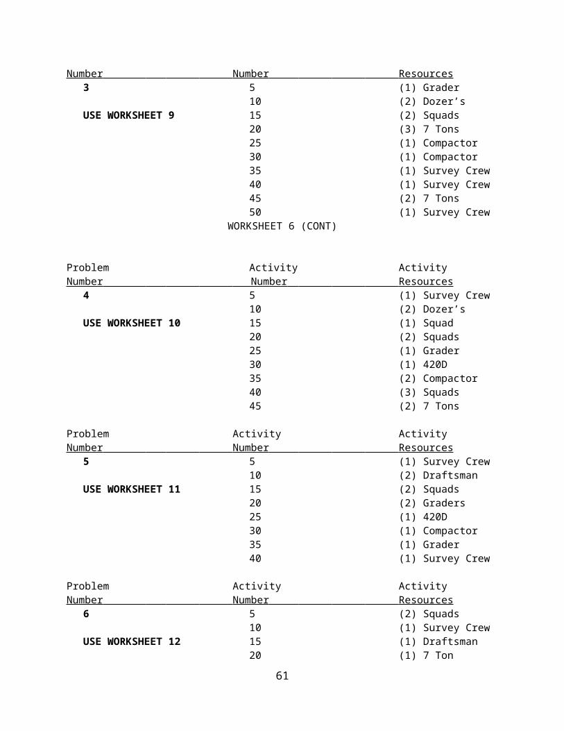
3 5 (1) Grader10 (2) Dozer’s
USE WORKSHEET 9 15 (2) Squads20 (3) 7 Tons25 (1) Compactor30 (1) Compactor35 (1) Survey Crew40 (1) Survey Crew45 (2) 7 Tons50 (1) Survey Crew
50

WORKSHEET 6 (CONT)
Problem Activity ActivityNumber Number Resources
4 5 (1) Survey Crew10 (2) Dozer’s
USE WORKSHEET 10 15 (1) Squad20 (2) Squads25 (1) Grader30 (1) 420D35 (2) Compactor40 (3) Squads45 (2) 7 Tons
Problem Activity ActivityNumber Number Resources
5 5 (1) Survey Crew10 (2) Draftsman
USE WORKSHEET 11 15 (2) Squads20 (2) Graders25 (1) 420D30 (1) Compactor35 (1) Grader40 (1) Survey Crew
Problem Activity ActivityNumber Number Resources
6 5 (2) Squads10 (1) Survey Crew
USE WORKSHEET 12 15 (1) Draftsman20 (1) 7 Ton25 (1) Grader30 (1) 420D35 (1) Tram40 (3) Squads45 (1) Compactor
51

WORKSHEET 7
52

53

WORKSHEET 8
54

WORKSHEET 9
55

56

WORKSHEET 10
57

58

WORKSHEET 11
59

WORKSHEET 12
60
61