
Engine - University of Michiganannastef/FuelCellPdf/vgt6c.pdf · harged Diesel Engines for Reduced...
12
N tc ρ 2 P 2 F 2 ρ 1 P 1 F 1 N EGR W f Variable Geometry Turbine W c1 W t W 21 Engine W 1e Compressor Intake Manifold Exhaust Manifold
-
Upload
hoanghuong -
Category
Documents
-
view
221 -
download
0
Transcript of Engine - University of Michiganannastef/FuelCellPdf/vgt6c.pdf · harged Diesel Engines for Reduced...
Control of Variable Geometry Turbocharged Diesel
Engines for Reduced Emissions�
A� G� Stefanopoulouz� I� Kolmanovsky��� J� S� Freudenberg�
z
Department of Mechanical and Environmental Engineering� UC� Santa Barbara� CA ������� Ford Research Laboratory� Ford Motor Company� Dearborn� MI ����
� Department of Electrical Engineering and Computer Science� University of Michigan� Ann Arbor� MI �����
Abstract
An emission control problem for an automotive direct injected compression ignition �diesel� engine equipped withexhaust gas recirculation �EGR� and a variable geometryturbocharger �VGT� is considered The objective is to operate the engine to meet driver�s torque demand and minimize NOx emissions while at the same time avoiding visiblesmoke generation It is demonstrated that the steadystateoptimization of engine emissions results in operating pointswhere EGR and VGT actuators are in e�ect redundant intheir e�ect on the variables that most directly a�ect theemissions A multivariable feedback controller is proposedwhich accounts for this actuator redundancy Furthermore�it coordinates the two actuators to fully utilize their jointe�ect on engine emission performance Experimental results con�rm good response properties of the proposed controller Keywords� Multivariable Control� Emission� Automotive
� Introduction
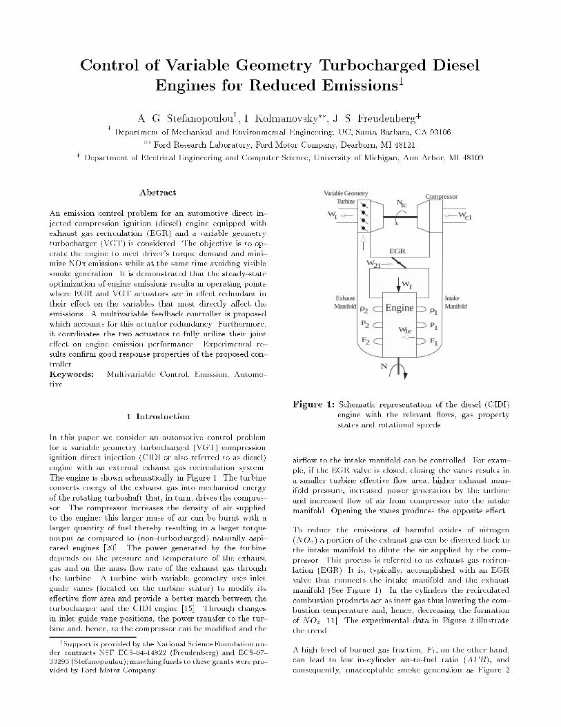
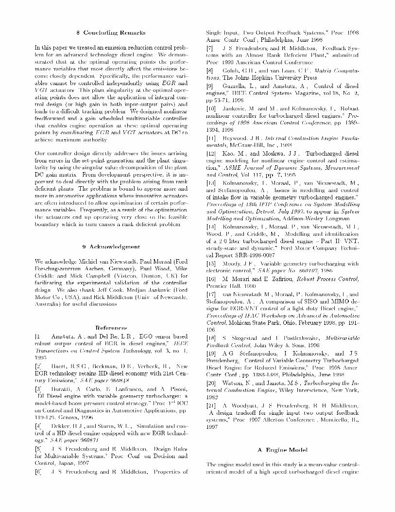
In this paper we consider an automotive control problemfor a variable geometry turbocharged �VGT� compressionignition direct injection �CIDI or also referred to as diesel�engine with an external exhaust gas recirculation system The engine is shown schematically in Figure � The turbineconverts energy of the exhaust gas into mechanical energyof the rotating turboshaft that� in turn� drives the compressor The compressor increases the density of air suppliedto the engine� this larger mass of air can be burnt with alarger quantity of fuel thereby resulting in a larger torqueoutput as compared to �nonturbocharged� naturally aspirated engines ��� The power generated by the turbinedepends on the pressure and temperature of the exhaustgas and on the mass �ow rate of the exhaust gas throughthe turbine A turbine with variable geometry uses inletguide vanes �located on the turbine stator� to modify itse�ective �ow area and provide a better match between theturbocharger and the CIDI engine ���� Through changesin inlet guide vane positions� the power transfer to the turbine and� hence� to the compressor can be modi�ed and the
�Support is provided by the National Science Foundation un�der contracts NSF ECS��������� �Freudenberg and ECS�������� �Stefanopoulou� matching funds to these grants were pro�vided by Ford Motor Company
Ntc
ρ2
P2
F2
ρ1
P1
F1
N
EGR
Wf
Variable GeometryTurbine
Wc1Wt
W21
Engine
W1e
Compressor
Intake Manifold
Exhaust Manifold
Figure �� Schematic representation of the diesel �CIDI�engine with the relevant �ows� gas propertystates and rotational speeds
air�ow to the intake manifold can be controlled For example� if the EGR valve is closed� closing the vanes results ina smaller turbine e�ective �ow area� higher exhaust manifold pressure� increased power generation by the turbineand increased �ow of air from compressor into the intakemanifold Opening the vanes produces the opposite e�ect
To reduce the emissions of harmful oxides of nitrogen�NOx� a portion of the exhaust gas can be diverted back tothe intake manifold to dilute the air supplied by the compressor This process is referred to as exhaust gas recirculation �EGR� It is� typically� accomplished with an EGRvalve that connects the intake manifold and the exhaustmanifold �See Figure �� In the cylinders the recirculatedcombustion products act as inert gas thus lowering the combustion temperature and� hence� decreasing the formationof NOx ���� The experimental data in Figure illustratethe trend
A high level of burned gas fraction� F�� on the other hand�can lead to low incylinder airtofuel ratio �AFR�� andconsequently� unacceptable smoke generation as Figure

demonstrates First� burned gas fraction from the EGRvalve displaces fresh air from the intake manifold and consequently decreases the fresh air mass �ows into the cylinders Secondly� a fraction of the exhaust gas that can be used bythe turbine is diverted through the EGR valve to the intakemanifold� reducing the turbine power and consequently the�ow delivered to the intake manifold through the compressor In this work� we show that the need to prevent smokegeneration will limit our ability to reduce NOx emissions The experimental data for NOx and smoke generation versus AFR are shown in Figure � Note that increase in theincylinder airtofuel ratio at constant fueling level and intake manifold pressure requires simultaneous reduction inthe burned gas fraction The decrease in burned gas fraction� consequently cause increased NOx emission The typical airtofuel ratio versus NOx emission curves shown inthe literature are for constant levels of burned gas fraction In contrast to the Figure � shown here� these typical �gures show NOx emission decreasing when airtofuel ratiois increasing
0 0.05 0.1 0.15 0.2 0.25 0.3 0.350
1
2
3
4
5
6
7
8
9
NO
x (g
/kW
hr)
and
smok
e (B
osch
Uni
ts)
F1 [f1] (none)
Wf=5-6 kg/hr,N=2480-2520 rpm for different MAPs
Mon Dec 21 03:42:25 EST 1998p1=140 kPap1=160 kPap1=180 kPa
NOx
Smoke
Figure �� Oxides of nitrogen and smoke generation versusburned gas fraction
In this paper� we �rst describe a procedure for generatingoptimal setpoints for F� and AFR as a function of fueling rate �Wf � and engine speed �N� Speci�cally� we usea nonlinear engine model �see Appendix A� to select desired steadystate operating points where the value of F�is maximized subject to the constraint that the AFR mustremain above an appropriate level that ensures that no visible smoke is generated from the engine Our next step isto develop a control scheme with the objective of regulatingthe performance variables to the optimized setpoints Theperformance variables are not measured directly and thecontrol scheme relies on the measurements of compressormass air �ow and absolute pressure in the intake manifold Two issues arise in the development of this control scheme Firstly� the fact that we have optimized the performancevariables implies that the desired operating points tend tolie on the boundary of the set of feasible engine operating points As a consequence� relatively small errors in thestrategy that generates the setpoints �e g due to interpolation of values in a lookup table� will tend to generateinfeasible setpoints Secondly� at the desired setpoints� the
20 25 30 35 40 45 50 550
1
2
3
4
5
6
7
NO
x (g
/kW
hr)
and
smok
e (B
osch
Uni
ts)
AFR [afr] (none)
Wf=4-5 kg/hr, N=2480-2520 rpm for different MAPs
p1=120 kPap1=140 kPap1=160 kPa
NOx
Smoke
Mon Dec 21 03:29:19 EST 1998
Figure �� Oxides of nitrogen and smoke generation versus incylinder airtofuel ratio Bosch � is considred visible smoke� Bosch is considered asafe bound for avoiding visible smoke Increasing AFR without maintaining constant dilution in the cylinders causes increased NOx generation
EGR and V GT actuators do not have the authority to manipulate AFR and F� independently� i e the actuators become essentially redundant The latter fact manifests itselfin that the DC gain matrix of the plant linearization at theoptimal operating point is almost rank de�cient To address these issues� we analyze the directional properties ofthe plant using the singular value decomposition ��� of theplant DC gain matrix We consequently propose a combination of nonlinear feedforward and gainscheduled linearfeedback controller architecture that accounts for this actuator redundancy Experimental results con�rm good response properties of the proposed control scheme Finally�in �Concluding Remarks�� we point out that the problemof actuator redundancy caused by the necessity to operateat optimized operating points may occur more frequentlyin automotive applications in the future due to tighteningemission regulations and performance requirements
For a comprehensive review of the state of the art in dieselengine control� including VGT control� see ��� and references therein Here we only comment on the papers thatare most relevant to the present investigation Reference ���reports on a control system development e�ort for a heavyduty diesel engine with EGR valve and VGT At tipins thecontrol system closes the EGR valve and uses a PID feedback on boost pressure to rapidly increase air supply to theintake manifold with VGT In conditions near steadystateoperation� the control system fully opens up the EGR valveand regulates the VGT vane position open loop to the setting required to achieve the desired EGR rate This strategy would be applicable to the vehicles that operate mostlyin steady state conditions� such as heavy commercial vehicles The approach of treating fast transient operation andclose to steadystate operation di�erently is motivated to alarge extent by the multiple objectives of the control designsuch as acceleration performance �pointwise in time con
straints on smoke� and emission performance �constraintson the averaged performance over a driving cycle� See alsoa related discussion in ��� ��� Reference �� also considersa heavyduty engine with EGR valve and VGT that areopenloop controlled to their desired settings determinedbased on the values of the engine speed and fueling rate Reference ���� reports on the development of a multivariable PI feedback controller for controlling EGR and VGTbased on measurements of intake manifold pressure andcompressor mass air �ow The feedback controller is developed using modelbased linearization� a �xed structureH� optimizationbased design and gainscheduling Thesetpoints for the controller in ���� are developed for minimum fuel consumption subject to airtofuel ratio constraintto prevent visible smoke Here the setpoints are developedso that the aggressive objectives of NOx emission reductionare incorporated As will be demonstrated in this paperthe need to sustain the operation of the engine at theseNOx emission friendly setpoints lead to a di�erent multivariable controller architecture than in ���� A nonlinearcontrol design methodology based on the method of Control Lyapunov functions and domination redesign is appliedto control of EGR valve and VGT in ���� As in ����� in���� the important interplay between setpoint selection andcontroller architecture remain unexplored
� Performance Objectives
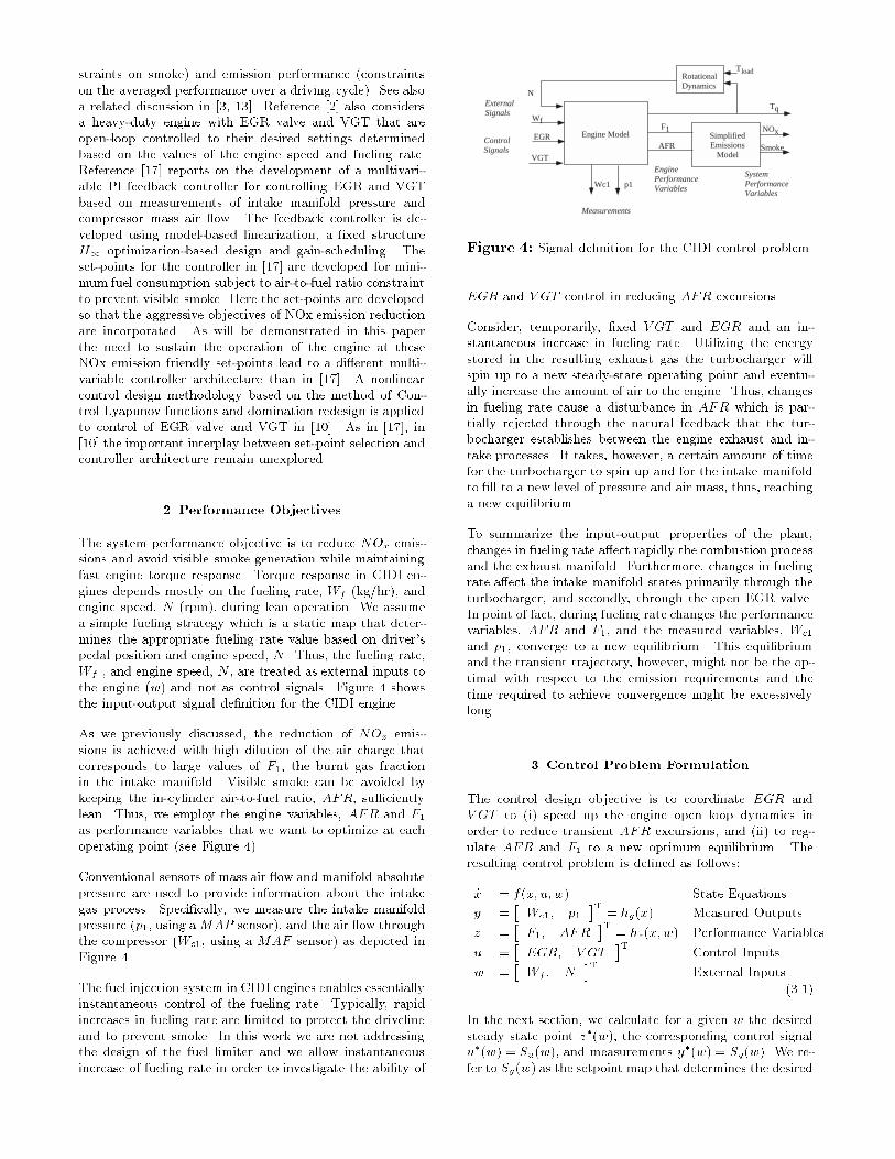
The system performance objective is to reduce NOx emissions and avoid visible smoke generation while maintainingfast engine torque response Torque response in CIDI engines depends mostly on the fueling rate� Wf �kg�hr�� andengine speed� N �rpm�� during lean operation We assumea simple fueling strategy which is a static map that determines the appropriate fueling rate value based on driver�spedal position and engine speed� N Thus� the fueling rate�Wf � and engine speed� N � are treated as external inputs tothe engine �w� and not as control signals Figure � showsthe inputoutput signal de�nition for the CIDI engine
As we previously discussed� the reduction of NOx emissions is achieved with high dilution of the air charge thatcorresponds to large values of F�� the burnt gas fractionin the intake manifold Visible smoke can be avoided bykeeping the incylinder airtofuel ratio� AFR� su�cientlylean Thus� we employ the engine variables� AFR and F�as performance variables that we want to optimize at eachoperating point �see Figure ��
Conventional sensors of mass air �ow and manifold absolutepressure are used to provide information about the intakegas process Speci�cally� we measure the intake manifoldpressure �p�� using aMAP sensor�� and the air �ow throughthe compressor �Wc�� using a MAF sensor� as depicted inFigure �
The fuel injection system in CIDI engines enables essentiallyinstantaneous control of the fueling rate Typically� rapidincreases in fueling rate are limited to protect the drivelineand to prevent smoke In this work we are not addressingthe design of the fuel limiter and we allow instantaneousincrease of fueling rate in order to investigate the ability of
Engine Model
RotationalDynamics
SimplifiedEmissions
Model
Wf
EGR
VGT
N
Tq
NOx
Smoke
F1
AFRControlSignals
EnginePerformanceVariables
SystemPerformanceVariables
Measurements
Wc1 p1
ExternalSignals
Tload
Figure �� Signal de�nition for the CIDI control problem
EGR and V GT control in reducing AFR excursions
Consider� temporarily� �xed V GT and EGR and an instantaneous increase in fueling rate Utilizing the energystored in the resulting exhaust gas the turbocharger willspin up to a new steadystate operating point and eventually increase the amount of air to the engine Thus� changesin fueling rate cause a disturbance in AFR which is partially rejected through the natural feedback that the turbocharger establishes between the engine exhaust and intake processes It takes� however� a certain amount of timefor the turbocharger to spin up and for the intake manifoldto �ll to a new level of pressure and air mass� thus� reachinga new equilibrium
To summarize the inputoutput properties of the plant�changes in fueling rate a�ect rapidly the combustion processand the exhaust manifold Furthermore� changes in fuelingrate a�ect the intake manifold states primarily through theturbocharger� and secondly� through the open EGR valve In point of fact� during fueling rate changes the performancevariables� AFR and F�� and the measured variables� Wc�
and p�� converge to a new equilibrium This equilibriumand the transient trajectory� however� might not be the optimal with respect to the emission requirements and thetime required to achieve convergence might be excessivelylong
� Control Problem Formulation
The control design objective is to coordinate EGR andV GT to �i� speed up the engine open loop dynamics inorder to reduce transient AFR excursions� and �ii� to regulate AFR and F� to a new optimum equilibrium Theresulting control problem is de�ned as follows�
�x � f�x� u�w� State Equations
y ��Wc�� p�
�T� hy�x� Measured Outputs
z ��F�� AFR
�T� hz�x�w� Performance Variables
u ��EGR� V GT
�TControl Inputs
w ��Wf � N
�TExternal Inputs
�� ��
In the next section� we calculate for a given w the desiredsteady state point z��w�� the corresponding control signalu��w� � Su�w�� and measurements y
��w� � Sy�w� We refer to Sy�w� as the setpoint map that determines the desired

values for the measured outputs The controller is designedto ensure that in steadystate or whenever w is changingslowly z stays as close as possible to the desired z��w� Thecontroller consists of a feedforward part ufw � u� � Su�w�and a feedback part C�s� The feedback portion is employedto compensate for uncertainties� see Figure � We developa family of linear controllers for EGR and V GT actuators�parameterized by w�� that regulate z�t� to z
��w� as w variesin a small neighborhood of a nominal operating point de�ned by w� These linear controllers are then scheduled toobtain a controller de�ned over the entire operating region Figure � shows the controller structure
Σ-
Sy C(s)y
zw
w
u*
Σ
Su
u
y* Engine
Figure �� Nonlinear controller structure
To design one of these linear controllers� C�s�� considerthe linearization of the system at a nominal operatingpoint� w�� and its corresponding values of the control input u� � Su�w�� and the output y� � Sy�w�� Let �w��u� �y� and �z denote the deviations of the correspondingvariables from their nominal values Let Py�s� and Pz�s�denote the transfer function matrices from the input �uto the measured outputs �y and performance outputs �z�respectively Similarly� let Pwy�s� and Pwz�s� denote thetransfer function matrices from the input �w to the measured outputs �y and performance outputs �z� respectively Figure � shows the resulting blockdiagram of the linearizedclosed loop system Note that in Figure � we have also included the linearization of the setpoint map� DSy� and ofthe feedforward controller� DSu
ΣΣ-
Σ
DSy C(s) Py
Pwy
Pz
Pwz
δufb δy
δz
δw
δw
δufw
Σ
DSu
δuδufw
Figure �� Block diagram showing the linearized controlproblem
In Figure � we further simplify the block diagram of the linearized control problem by standard block diagram algebra Assuming small signal� the e�ects of the fuel disturbancein the output and the feedforward controller signal can be
moved in the setpoint generation These manipulations�however� hold only for linear plants and the uncertaintiesintroduced by nonlinear high order terms or other modeling errors will be treated as input disturbances to the closedloop �dI � and dOy respectively� It will be shown that thelinear controller C�s� ensures robust feedback propertiesagainst input and output disturbances
ΣΣ
-
Σ
DSy-PyDSu-Pwy C(s) Py
Pz
Pwz
δy
δz
δw
δwΣ
δu
dI doy
Figure �� Simpli�ed linear robust control problem
� Steady�State Optimization
The desired steadystate values for the burnt gas fractionand airtofuel ratio� z�� are generated using the following procedure Given w� we search for the operating pointu � u��w� so that F� is maximized subject to �� � incylinder airtofuel ratio� AFR� being greater than AFRand � � intake manifold pressure� p�� being less than �p� The �rst constraint ensures that no visible smoke is generated in steadystate The lower bound AFR can be afunction of fueling rate and engine speed For simplicity�however� we assume a constant bound AFR � � Thesecond constraint protects the engine from damage due tohigh intake manifold pressure �overboost� We assume that�p� � � kPa The value of F� is maximized to achieveNOx reduction After selecting the desired setpoints forthe performance variables� z�� and its associated inputs�u�� we determine the corresponding measured outputs� y��using simulation of the engine model
In Figures � to �� we illustrate the procedure for generating desired setpoints by assuming speci�c external inputs�Wf � � kg�hr and N � ��� rpm We show how to determine the actuator positions� EGR� and V GT �� that correspond to maximum F� for AFR � AFR A grid that spansthe feasible set for the controller inputs u is selected Thegrid is based on the actuator authority� speci�cally� EGRand V GT actuator positions vary between � and �� where� corresponds to the completely closed position and � corresponds to the completely open position as shown in Figure � The signi�cance of the region enclosed by the smallbox in Figure � is explained in the following section The setof all steadystate points for the performance variables� z�that correspond to Wf � � kg�hr� N � ��� rpm is shownin Figure � Similarly� the set of all steadystate points forthe measured outputs� y� that correspond to Wf � � kg�hr�N � ��� rpm are shown in Figure �� The circles indicatethe equilibria that satisfy the constraints� the �x�s thosethat violate the constraints Our procedure for setpointgeneration indicates that F �� � ��� and AFR� � ����is to be chosen for this engine speed and load values This
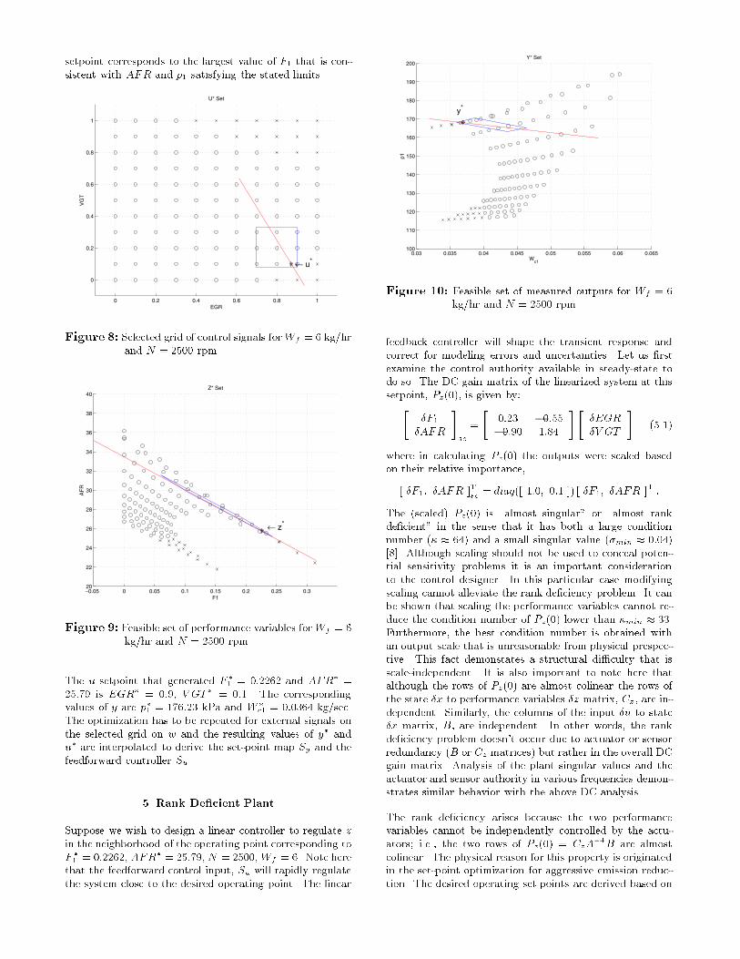
setpoint corresponds to the largest value of F� that is consistent with AFR and p� satisfying the stated limits
0 0.2 0.4 0.6 0.8 1
0
0.2
0.4
0.6
0.8
1
EGR
VG
T
U* Set
← u*
Figure � Selected grid of control signals forWf � � kg�hrand N � ��� rpm
−0.05 0 0.05 0.1 0.15 0.2 0.25 0.320
22
24
26
28
30
32
34
36
38
40
F1
AF
R
Z* Set
← z*
Figure � Feasible set of performance variables forWf � �kg�hr and N � ��� rpm
The u setpoint that generated F �� � ��� and AFR� ����� is EGR� � ���� V GT � � ��� The correspondingvalues of y are p�� � ����� kPa and W �
c� � ������ kg�sec The optimization has to be repeated for external signals onthe selected grid on w and the resulting values of y� andu� are interpolated to derive the setpoint map Sy and thefeedforward controller Su
� Rank De�cient Plant
Suppose we wish to design a linear controller to regulate zin the neighborhood of the operating point corresponding toF �� � ���� AFR
� � �����N � ����Wf � � Note herethat the feedforward control input� Su will rapidly regulatethe system close to the desired operating point The linear
0.03 0.035 0.04 0.045 0.05 0.055 0.06 0.065100
110
120
130
140
150
160
170
180
190
200
Wc1
p1
Y* Set
y*
Figure ��� Feasible set of measured outputs for Wf � �kg�hr and N � ��� rpm
feedback controller will shape the transient response andcorrect for modeling errors and uncertainties Let us �rstexamine the control authority available in steadystate todo so The DC gain matrix of the linearized system at thissetpoint� Pz���� is given by��
�F��AFR
�sc
�
���� ���������� ����
���EGR�V GT
��� ��
where in calculating Pz��� the outputs were scaled basedon their relative importance�
� �F�� �AFR �Tsc� diag�� ���� ��� �� � �F�� �AFR �
T �
The �scaled� Pz��� is �almost singular� or �almost rankde�cient� in the sense that it has both a large conditionnumber �� � ��� and a small singular value ��min � �������� Although scaling should not be used to conceal potential sensitivity problems it is an important considerationto the control designer In this particular case modifyingscaling cannot alleviate the rank de�ciency problem It canbe shown that scaling the performance variables cannot reduce the condition number of Pz��� lower than �min � �� Furthermore� the best condition number is obtained withan output scale that is unreasonable from physical prespective This fact demonstates a structural di�culty that isscaleindependent It is also important to note here thatalthough the rows of Pz��� are almost colinear the rows ofthe state �x to performance variables �z matrix� Cz � are independent Similarly� the columns of the input �u to state�x matrix� B� are independent In other words� the rankde�ciency problem doesn�t occur due to actuator or sensorredundancy �B or Cz matrices� but rather in the overall DCgain matrix Analysis of the plant singular values and theactuator and sensor authority in various frequencies demonstrates similar behavior with the above DC analysis
The rank de�ciency arises because the two performancevariables cannot be independently controlled by the actuators� i e � the two rows of Pz��� � CzA
��B are almostcolinear The physical reason for this property is originatedin the setpoint optimization for aggressive emission reduction The desired operating set points are derived based on

maximization of the burned gas fraction for �xed airtofuelratio When the burnt gas fraction increases the fresh aircharge is displaced from the intake manifold and the incylinder airtofuel ratio� AFR� decreases Let us considerthe de�nition of incylinder airtofuel ratio �� ��
AFR � ��� F��W�e
Wf
� �� �
where W�e is the engine intake mass �ow rate� F� is theburned gas fraction and Wf is the fueling rate The maximization of F� for �xed AFR is achieved for VGT and EGRpositions that maximize W�e Thus� at least locally� VGTand EGR cannot a�ect W�e Denote by � the attainedmaximum value of W�e at the desired point Then �� �becomes
�AFR � ���F� �� ��
which results in completely coupled outputs We note thatthe DC gain matrix Py��� is relatively wellconditioned�which re�ects the fact that EGR and VGT have independent authority to regulate the measured outputs fromequivalent deviations from the equilibrium
The fact that the actuators are locally almost redundantis also illustrated in Figures � to �� Consider how theperformance variables change as the actuators move in asmall region about the nominal setpoint given in Figure � The size of this region in u� is chosen so that the nonlinear plant transformations from u to y and z can be approximated with the linear plant transformations Py��� andPz��� Mapping this set of control commands into the performance and measured outputs gives us the regions shownin Figures � and �� Note that the region in Figures � isessentially a line in AFR and F� coordinates Were theactuators completely redundant� in the sense that they hadidentical e�ect on performance variables� this skinny regionwould reduce to a line similar to the one shown in Figure � On the other hand� the region in the y coordinates indicatesindependent control of the measurements in steadystate byusing EGR and V GT
The consequence of the rank de�cient Pz��� can now be recognized Small errors in the steadystate scheduling schemethat correspond to z� outside the skinny set will result iny� set points outside the feasible set of Wc� and p� Acontroller that enforces y�t� to converge to y� using highgain in both EGR and V GT actuators may cause saturation of both actuators or may result in large actuator e�ortsand sensitivity In light of this di�culty a possible solutionis to generate a di�erent setpoint strategy that results inengine operation away from �optimal� but �di�cult� setpoints However� this solution would degrade emission performance of the engine and may be undesirable due to verystringent emission regulations that are currently being putin place
Feedback Controller
A feedback controller that allows robust engine operationat the optimal �F�� AFR�
T � z� is presented below Theoptimum region is narrow and close to the boundary of thefeasible region of operation Because the setpoint generation may entail large errors due to model uncertainty and
numerical interpolations� there is a large probability for infeasible setpoints z� Any high gain feedback controller �inboth actuators� will attempt to track both feasible and infeasible commands using large control signals and causingfrequent actuator saturation Instead as we demonstratebelow� a feedback controller based on a single integratordesign �high gain in a selected direction� can achieve goodperformance with small control signals We refer to thiscontroller as a �directional� compensator
In the following subsections we design the directional compensator with a single integrator to coordinate the actuatorsto achieve maximum authority and to reduce the impact ofstrategy errors by not attempting to track infeasible setpoints To do that we �rst assume that we can measure theperformance variables �z We design the controller basedon the directional properties of the plant Pz using the singular value decomposition of the plant DC gain matrix Thisanalysis identi�es the e�ective range of the plant� which determines the set of setpoints that may be tracked withoutincurring excessively large control signals� and the e�ectiverowspace of the plant� which determines how the actuatorsshould be coordinated to achieve maximum authority Wethen translate our feedback controller to �lter the measured�y� commands that correspond to infeasible �z� commandsand analyze the performance and robustness properties ofthe resulting feedback loop Finally� we gain schedule thefeedback controller to span the entire operating range of theengine
� Feedback on Performance Variables
Consider the singular value decomposition �SVD� of Pz����
Pz��� � ��u�vT� � ��u�v
T� �� ��
where �� � �� are the largest and smallest singular valuesof Pz���� and �u�� u�� and �v�� v�� are the correspondingsets of left and right singular vectors� respectively Supposetemporarily that Pz��� were rank de�cient� so that �� � � Then it is not possible to track an arbitrary setpoint command� the set of commands that can be tracked is givenby the range� or columnspace� of Pz���� R�Pz���� � R�u�� For our problem� Pz��� is �almost� rank de�cient� in thesense that � � �� � � It follows that certain commandscan be tracked only by using large control inputs To seethis� consider a command �z�� together with the corresponding steady state control signal �u Using the SVD�we have that
�uss � ������ v�uT� �z
� � ������ v�uT� �z
�� �� �
Hence if �z� � �u� for a scalar �� then k�uk ������� k�z�k � k�z�k� where we denote by k � k the vector�norm It follows that relatively small commands may result in large control signals On the other hand� commandsthat satisfy �z� � R�u�� may be tracked without using largecontrol signals� we say that such commands lie in the �e�ective range� of the plant A controller with an integrator foreach inputoutput pair will thus achieve perfect steady statetracking of all commands at the expense of large controlsignals� which are undesirable because they may result inactuator saturation Although saturation isn�t necessarilybad� it is di�cult to analyze for systems with multiple actuators and strong interactions� and it often has the potential

to degrade performance in an unpredictable way Similarcomments apply to controllers whose DC gain is �nite butvery large
To avoid potential di�culties with large control signals�we propose a controller of the form C�s� � GzKC�s�Hz�where Gz � R��� and Hz � R��� are constant unit vectorsand KC�s� is a stabilizing controller with integral action�Figure ��� To simplify the controller implementation andgainscheduling a simple PI controller for KC has been chosen We choose Hz and Gz based on the following considerations�
�i� Hz enforces tracking of commands that lie in the �effective range� of the plant Pz���� Hz � uT�
�ii� Gz minimizes the control e�ort that is needed to trackfeasible commands� Gz � v�
KC(s) ΣΣ
-Pz(s)
δzΣ
Σ
GzHz
δz*dOz
dI
n
Figure ��� Linear feedback controller based on measuringthe performance variables
Recall here that because Pz��� is almost singular there exist many control signals �u that will result in the similarsteadystate �z Having Hz and Gz we form the singleinputsingleoutput �squareddown� plant HzPz�s�Gz� which wedenote by �square down� plant� or �sd� �shown in Figure �� The �sd� plant has nonzero DC gain and we cantune a PI controller to achieve steadystate tracking of thecommands that lie in the e�ective range of the plant at DC Apart from steady state behavior� the PI controller can betuned to achieve fast response taking into account bandwidth contraints imposed in the IO con�guration by theavailable actuators and sensors The speci�cations on thetransient characteristics have to re�ect constraints in themeasured variables and the performance variables simultaneously and it is the subject of current research ���
KC(s)Σ
-HzPz(s)Gz
esd usd
Figure ��� Single input� single output ��squaredown��plant
With the current choice of Hz � uT� and Gz � v� the steadystate control signal� �uss� to a command �z
� � ��u����u�for some scalar ��� and �� is
�uss � GzHz�z���HzPz���Gz� � ��v����� �� ��
which is the smallest control signal that achieves at steadystate tracking of the feasible command component Indeed�the steady state output is �zss � Pz����u � ��u�
It is particularly interesting to investigate the robustnessproperties of the resulting IO feedback controller Therobustness and performance properties of the IO feedbacksystem assuming measured performance variables provide abenchmark of how well we can do given appropriate sensorsfor the rank de�cient plant It is expected that these properties will degrade in the case when the measured variablesare di�erent from the performance variables We introducethe notation for sensitivity and complementary sensitivityfunctions
SOz �s� � �I � Pz�s�C�s����� TOz �s� � I � SOz �s�
SIz �s� � �I �C�s�Pz�s����� TIz �s� � I � SIz �s��� ��
The closed loop system behavior in tracking� disturbancerejection� noise attenuation and output uncertainties is determined by the output sensitivity and complementary sensitivity functions For example� if we assume step inputs forall exogenous inputs in Figure �� �dOz �t� � dOz��t� etc ��the steady state error is given by
ess � SOz ����z��SOz ���dOz � SOz ���Pz���dIz �SOz ���n�
Similarly� the controller response and closed loop stabilityrobustness against input uncertainties is determined by theinput sensitivity and complementary sensitivity functions�
uss � SIz ���dIz � lims���C�s�SOz �s����z
� � dOz � n��
The sensitivity and complementary sensitivity functionsof the �sd� plant shown in Figure �� Ssd�s� � ���� �HzPz�s�Gz�� and Tsd�s� � HzPz�s�Gz��� � HzPz�s�Gz��respectively� are directly shaped based on the PI controllergains Stability of the �sd� plant implies that Ssd��� � �and Tsd��� � � Although Ssd��� and Tsd��� are importantfor the stability and performance of the feedback systemthey are only indirectly related to the IO stability robustness properties Recall here that by using the directionalcompensator GzKCHz we cannot track all commands� thusthe output sensitivity and complementary sensitivity functions for the IO plant in Figure �� at DC must satisfykSOz ���k � � and kTOz ���k � � It is important� to notethat the choices of Gz � v� and Hz � uT� achieve the minimum value �see Appendix B� and result in�
kSOz ���k � kTOz ���k � kSIz ���k � kTIz ���k � ��
Thus� the particular choices for Hz and Gz ensure reasonable stability robustness against output and input plantuncertainties We complete now the analysis of the performance and robustness characteristics for the system whenthe measured outputs are di�erent from the performanceoutputs which is the desired implementation con�guration
� Feedback on Measured Variables
The directional compensator of the previous subsectionneeds to be modi�ed for implementation based on the measured variables �y instead of the performance variables �z The DC gain matrix of the input to measurements Py��� iswell conditioned for the majority of the operating points The reference inputs are �y� � Py���Pz���
���z� Let thesingular controller be C�s� � GyKC�s�Hy with H
Ty and Gy
constant matrices in R��� and KC�s� a PI controller

We choose Hy so that the controller attempts to track onlythose ycommands that correspond to zcommands that liein the e�ective range of Pz����
Hy � HzPz���P��y ����kHzPz���P
��y ���k� �� ��
where Hz � uT� as above The transfer function mapping ycommands to the control signal inFigure �� is given by C�s� �I � Py�s�C�s��
��� andhas DC gain of magnitude kGyHyk�jHyPy���Gyj �kGyHzPz���P
��y ���k�jHzPz���Gyj Because HzPz���Gy �
��vT� Gy� it is easy to verify that choosing Gy � v� �i e �
Gy � Gz independently of the sensor set� minimizes thesize of the steady state control signal Indeed� a referencecommand
�y� � ��Py���Pz�����u�� �z �
feasible component
���Py���Pz�����u� �� ��
will generate the steady state control signal
�uss � GyHy�y���HyPy���Gy�
� v�uT� Pz���Py���
���y���HyPy���Gy�� ��v�����
�� ��
Moreover� the combination of Hy and Gy ensures that thesmallest control signal will be used to achieve steady statetracking of the component of �y that corresponds to thee�ective range of the performance variables To see thatconsider the control signal from Eq � �� then the measuredoutput is
�yss � Py����uss � ��Py���v���� � ��Py���Pz�����u�
which is the feasible component of the reference input Forillustration in Figure � we show the line on which the actuator signals lie as speci�ed by Gz � v� Similarly� theline in Fig � shows the direction Pz���Gz and the line inFig �� shows the direction Py���Gz Note also that atDC the singleinput singleoutput system ��sd� plant� thatemerges from the Py��� based feedback is equivalent to the�sd� plant that is based on measuring the performance variables directly� i e � HyPy���Gy � HzPz���Gz
The input and output robustness properties of the resultingfeedback loop determine the closed loop behavior for
�i� actuator uncertainties or errors in the feedforwardstrategy �u��w� � DSu�w
� �de�ned in Sec �� Fig � �
�ii� sensor uncertainties or modeling errors of the fuelingdisturbance Pwy�w
� in the measured variables andPwz�w
� in the performance variables
In particular the e�ect of EGR and VGT actuator uncertainties can be investigated based on the e�ect of an inputdisturbance dI�t� � dI��t� as shown in the Figure �� Thesteady state control signal is determined by �uss � SIy ���dIwhere
SIy ��� � I �GyHyPy�����HyPy���Gy�� I �GzHzPz�����HzPz���Gz�� SIz ���
�� ��
Thus� kSIy ���k � kSIz ���k and the input robustness properties of the feedback system are preserved when �y is measured instead of �z This is due to the topology of the inputdisturbance in the feedback loop
Modeling errors in the interaction between fuel and the performance variables Pwz can be expressed as an output multiplicative uncertainty and assessed through the e�ects ofan output disturbance dOz �t� � dOz��t� to the Pz�s� plant Obviously the output disturbance dOz �t� does not a�ect themeasured variables and cannot be rejected
Finally� to assess the importance of modeling errors in thePwy term and sensor uncertainties we analyze the e�ects ofstep output disturbance dOy �t� � dOy��t� to �y These aredetermined by �yss � SOy ���dOy � where
SOy ��� � I � Py���GyHy��HyPy���Gy�� I � Py���GzHzPz���Py���
����HzPz���Gz��� ��
and� in general� kSOy ���k � kSOz ���k depending on the angle yz � � �HT
y � Py���Gy� In particular� it is shown in ���that kSOy ���k � ��cos�yz� The physical interpretationis clear� to have good output robustness and steady statetracking of �yss� the range of the achievable steady statemeasured outputs� R�Py���Gy�� has to correspond to therange of the feasible component of the �y� which is R�HT
y ��see also Eq � �� Therefore� the output feedback propertieswill be preserved if the angle
cosyz � cos� �HTy � Py���Gy� � cos� �Py���
�T v�� Py���v��
is small which is ensured if the DC gain matrix Py��� is wellconditioned
In the few operating points that an illconditioned Py���matrix is obtained through the linearization we check explicitly the angle yz to assess the potential degradation This angle remained small over the entire optimized operating region of the engine It is intuitively clear that the caseswhere the angle yz will be large are the cases where themeasurements do not correlate well with the performancevariables
KC(s) ΣΣ
-Py(s)
δyΣ
Σ
GzHz
δy* dOydI
n
Pz(0)Py(0)-1
Pz(s) Σ
dOz
δz
Hy
Figure ��� Linear feedback controller
We note here that di�erential sensitivity calculations can beused to analyze the sensitivity of the closed loop due to errors or uncertainty in the e�ective range of the plant Pz��� Having small SIy and SOy is a necessary condition for reducing the sensitivity of the closed loop performance andstability robustness against these uncertainties� but furtherwork is needed to determine the exact relations This isgoing to be the subject of future work
0 10 20 300.02
0.03
0.04
0.05
0.06
Wc1
Measurements
0 10 20 30150
160
170
180
190
200
210
220
p 1
Seconds
0 10 20 300.2
0.4
0.6
0.8
1
EG
R
Control Signals
0 10 20 30−0.1
0
0.1
0.2
0.3
0.4
VG
Seconds
0 10 20 300
0.1
0.2
0.3
0.4
F1
Performance
0 10 20 3015
20
25
30
35
AF
R
Seconds
Figure ��� Simulation response of the two integrator�dashed� and the single integrator �solid� controllers The setpoints are indicated by thedotted line
� Simulation and Experimental Results
The di�erences between a two integrator controller and thesingle integrator controller� C�s� � GzKc�s�Hy� can bedemonstrated by simulating the linearized model The controller with two integrators was designed so that asymptotic tracking of the setpoints by the measured outputs isenforced� and by applying the LQG control design methodology to the augmented plant The PI controller for theSISO plant HyPyGz was tuned to achieve satisfactory response without violating bandwidth constraints imposedby the cuto� frequency of the actuator The responsesof the two controllers to fuel steps between the levels�� ���� ���� ���� ���� ���� ���� ���� ��� kg�hr at ��� rpm areshown in Figure �� We observe that the single integrator controller requires less actuator position deviations fromtheir nominal positions� and while strict tracking of themeasured outputs �Wc� and p�� is not enforced� the deterioration in the values of performance outputs �F� andAFR� is very small For example� at t � �� seconds thetwo integrator controller closes V GT beyond its physicallimits �limits were not enforced in this linear simulation�while the single integrator controller closes V GT only toabout ��� This results in an error of about �� kPa in p�tracking which translates only to very small performanceoutput errors Smaller actuator e�ort inherent to the operation of the single integrator controller makes actuatorsaturation and loss of linear performance associated withactuator saturation and antiwindup less frequent
The experimental test of the controller was done in a Visteon�s engine dynomometer in Dunton� UK using dSPACErapid prototyping environment The matrices Gz and Hy
were determined for each operating point in the same gridof engine speed and fueling rate values as was used to generate the setpoints The gainscheduling of the controllerwas accomplished by linearly interpolating the values of theentries of the matrices Gz and Hy for all engine speed and
0 10 20 3060
80
100
120
140
160
Wc1
Measurements
0 10 20 30
100
120
140
160
180
200
p 1
Seconds
0 10 20 300
20
40
60
80
100
120
EG
R
Control Signals
0 10 20 300
20
40
60
80
100
VG
T
Seconds
0 10 20 3010
20
30
40
50Performance
AF
R
0 10 20 300
0.1
0.2
0.3
0.4
0.5
F1
Seconds
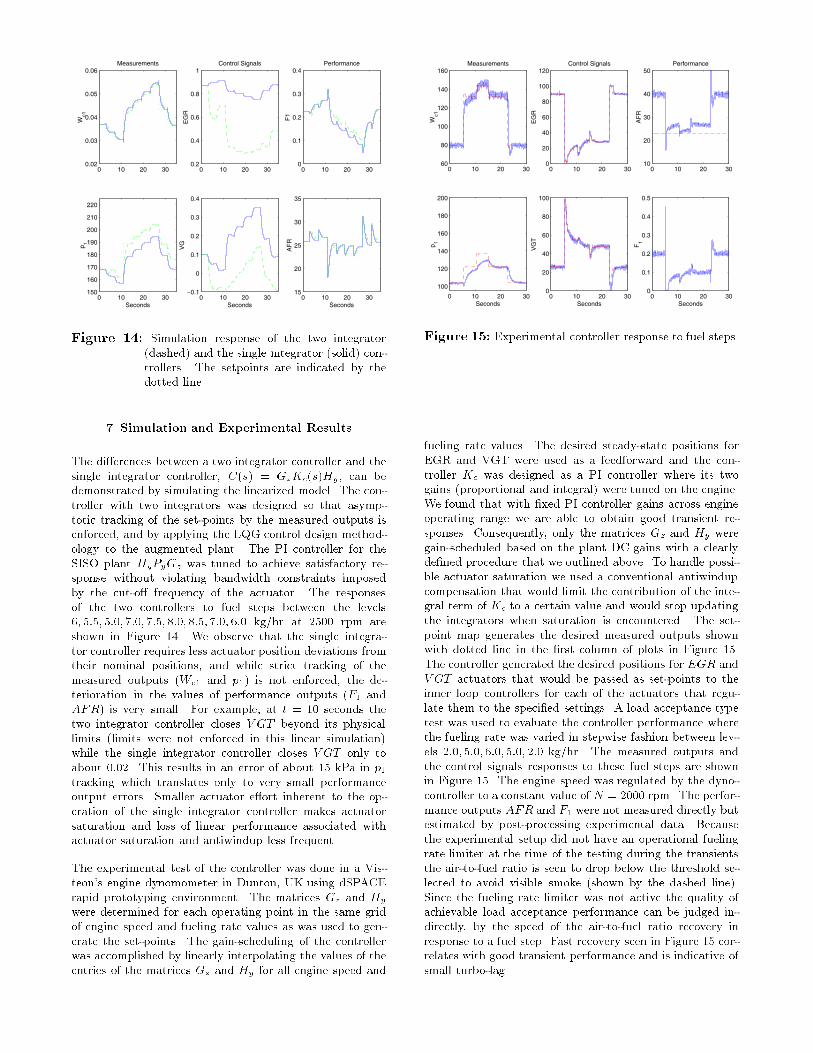
Figure ��� Experimental controller response to fuel steps
fueling rate values The desired steadystate positions forEGR and VGT were used as a feedforward and the controller Kc was designed as a PI controller where its twogains �proportional and integral� were tuned on the engine We found that with �xed PI controller gains across engineoperating range we are able to obtain good transient responses Consequently� only the matrices Gz and Hy weregainscheduled based on the plant DC gains with a clearlyde�ned procedure that we outlined above To handle possible actuator saturation we used a conventional antiwindupcompensation that would limit the contribution of the integral term of Kc to a certain value and would stop updatingthe integrators when saturation is encountered The setpoint map generates the desired measured outputs shownwith dotted line in the �rst column of plots in Figure �� The controller generated the desired positions for EGR andV GT actuators that would be passed as setpoints to theinner loop controllers for each of the actuators that regulate them to the speci�ed settings A load acceptance typetest was used to evaluate the controller performance wherethe fueling rate was varied in stepwise fashion between levels ��� ���� ���� ���� �� kg�hr The measured outputs andthe control signals responses to these fuel steps are shownin Figure �� The engine speed was regulated by the dynocontroller to a constant value of N � ��� rpm The performance outputs AFR and F� were not measured directly butestimated by postprocessing experimental data Becausethe experimental setup did not have an operational fuelingrate limiter at the time of the testing during the transientsthe airtofuel ratio is seen to drop below the threshold selected to avoid visible smoke �shown by the dashed line� Since the fueling rate limiter was not active the quality ofachievable load acceptance performance can be judged indirectly� by the speed of the airtofuel ratio recovery inresponse to a fuel step Fast recovery seen in Figure �� correlates with good transient performance and is indicative ofsmall turbolag
� Concluding Remarks
In this paper we treated an emission reduction control problem for an advanced technology diesel engine We demonstrated that at the optimal operating points the performance variables that most directly a�ect the emissions become closely dependent Speci�cally� the performance variables cannot be controlled independently using EGR andV GT actuators This plant singularity at the optimal operating points does not allow the application of integral control design �or high gain in both inputoutput pairs� andleads to a di�cult tracking problem We designed nonlinearfeedforward and a gain scheduled multivariable controllerthat enables engine operation at these optimal operatingpoints by coordinating EGR and V GT actuators at DC toachieve maximum authority
Our controller design directly addresses the issues arrisingfrom errors in the setpoint generation and the plant singularity by using the singular value decomposition of the plantDC gain matrix From development perspective� it is important to deal directly with the problem arising from rankde�cient plants The problem is bound to appear more andmore in automotive applications where innovative actuatorsare often introduced to allow optimization of certain performance variables Frequently� as a result of the optimizationthe actuators end up operating very close to the feasibleboundary which in turn causes a rank de�cient problem
Acknowledgment
We acknowledge Michiel van Niewstadt� Paul Moraal �FordForschugszentrum Aachen� Germany�� Paul Wood� MikeCriddle and Mick Campbell �Visteon� Dunton� UK� forfacilitating the experimental validation of the controllerdeisgn We also thank Je� Cook� Mrdjan Jankovic �FordMotor Co � USA�� and Rick Middleton �Univ of Newcastle�Australia� for useful discussions
References
��� Amstutz� A � and Del Re� L R � �EGO sensor basedrobust output control of EGR in diesel engines�� IEEE
Transactions on Control System Technology� vol �� no ������
�� Baert� R S G � Beckman� D E � Verbeek� R � �NewEGR technology retains HD diesel economy with �st Century Emissions�� SAE paper ������
��� Buratti� A Carlo� E Lanfranco� and A Pisoni��DI Diesel engine with variable goemetry turbocharger� amodelbased boost pressure control strategy�� Proc �st ICCon Control and Diagnostics in Automotive Applications� pp ������ Genova� ����
��� Dekker� H J � and Sturm� W L � �Simulation and control of a HD diesel engine equipped with new EGR technology�� SAE paper ������
��� J S Freudenberg and R Middleton� �Design Rulesfor Multivariable Systems�� Proc Conf on Decision andControl� Japan� ����
��� J S Freudenberg and R Middleton� �Properties of
Single Input� Two Output Feedback Systems�� Proc ����Amer Contr Conf � Philadelphia� June ����
��� J S Freudenberg and R Middleton� �Feedback Systems with an Almost Rank Defecient Plant�� submittedProc ���� American Control Conference
��� Golub� G H � and van Loan� C F � Matrix Computa
tions� The Johns Hopkins University Press
��� Guzzella� L � and Amstutz� A � �Control of dieselengines�� IEEE Control Systems Magazine� vol ��� No �pp ����� ����
���� Jankovic� M and M � and Kolmanovsky� I � �Robustnonlinear controller for turbocharged diesel engines�� Pro
ceedings of ���� American Control Conference� pp ��������� ����
���� Heywood� J B � Internal Combustion Engine Funda
mentals� McGrawHill� Inc � ����
��� Kao� M � and Moskwa� J J � �Turbocharged dieselengine modeling for nonlinear engine control and estimation�� ASME Journal of Dynamic Systems� Measurement
and Control� Vol ���� pp �� ����
���� Kolmanovsky� I � Moraal� P � van Nieuwstadt� M �and Stefanopoulou� A � �Issues in modelling and controlof intake �ow in variable geometry turbocharged engines��Proceedings of ��th IFIP Conference on System Modelling
and Optimization� Detroit� July ����� to appear in System
Modelling and Optimization� AddisonWesley Longman
���� Kolmanovsky� I � Moraal� P � van Nieuwstadt� M J �Wood� P � and Criddle� M � �Modelling and identi�cationof a � liter turbocharged diesel engine Part II� VNT�steadystate and dynamic�� Ford Motor Company Technical Report SRR��������
���� Moody� J F � �Variable geometry turbocharging withelectronic control�� SAE paper No ������� ����
���� M Morari and E Za�riou� Robust Process Control�Prentice Hall� ����
���� van Nieuwstadt M � Moraal� P � Kolmanovsky� I � andStefanopoulou� A � �A comparison of SISO and MIMO designs for EGRVNT control of a light duty Diesel engine��Proceedings of IFAC Workshop on Advanced in Automotive
Control� Mohican State Park� Ohio� February ����� pp ������
���� S Skogestad and I Postlethwaite� Multivariable
Feedback Control� John Wiley Sons� ����
���� A G Stefanopoulou� I Kolmanovsky� and J S Freudenberg� �Control of Variable Geometry TurbochargedDiesel Engine for Reduced Emissions�� Proc ���� Amer Contr Conf � pp ��������� Philadelphia� June ����
��� Watson� N � and Janota� M S � Turbocharging the Internal Combustion Engine� Wiley Interscience� New York����
��� A Woodyatt� J S Freudenberg� R H Middleton��A design tradeo� for single input two output feedbacksystems�� Proc ���� Allerton Conference � Monticello� IL�����
A Engine Model
The engine model used in this study is a meanvalue controloriented model of a high speed turbocharged diesel engine
with the variable geometry turbocharger and the exhaustgas recirculation The model is based on the standard representations for the gas �lling dynamics in the intake manifoldand the exhaust manifold� turbocharger dynamics� actuator dynamics and sensor dynamics The speci�c subsystemrepresentations and modelling assumptions are wellknownsee e g ��� �� ��� Here we follow ���� that provides careful treatment of the burnt gas fraction dynamics and VGTmodel� not available from other sources
We start by de�ning the actuator dynamics Stable innerloop controllers for the pneumatic EGR valve and VGTvane actuators are assumed and their closed loop behavior is incorporated in the engine model The closed loopdynamics are represented by a �rst order system which introduces two additional states� EGR valve position �egr��and VGT actuator position �vgt�
ddtegr � �
�e�EGR� egr� �
ddtvgt � �
�v�V GT � vgt� �
�� ��
The actuation signals� EGR and V GT � are generated bythe control system� and the time constants� �e and �v� areapproximately equal to � �� sec and � �� sec respectively Their scaled range is between � and �� where the positionof � is completely open and � is completely closed
The gas properties in the intake manifold are representedby three states� density ���� kg�m
��� pressure �p�� kPa�and burned gas fraction �F�� de�ned as the ratio of densityof burned gas to the total density of air and burned gasin the intake manifold The term �burned gas� refers tothe products of combustion �other than air� that are in theintake manifold due to EGR Note that since diesel enginesoperate lean the �ow through the EGR valve can contain asmuch as �fty percent of air Hence� the use of the burnedgas fraction is indispensible to keep track of the EGR
The equations for the gas �lling dynamics are derived onthe basis of the total and burned gas mass balances� idealgas law and energy balance under the adiabatic assumption For the intake manifold�
d
dt�� � �
V��Wc� �W�� �W�e� �
d
dtF� �
Wegr�F��F���WcF���V�
�
d
dtp� �
�R
V��Wc�Tc� �W��T� �W�eT�� �
�� �
Here V� is the intake manifold volume� Wc� is the mass �owrate through the compressor and Tc� is the temperature ofthis �ow� W�� is the EGR mass �ow rate� W�e is the total�ow mass �ow rate of gas from the intake manifold intothe engine �mean value averaged over an cycle�� T� is thetemperature of the gas in the intake manifold and T� is temperature of the gas in the exhaust manifold The ideal gaslaw is used to relate the temperature values to the pressureand density values� Ti � pi��R�i�� i � �� � The thermodynamic constants used throughout are the di�erence ofspeci�c heats at constant pressure and constant volume �R�kJ��kg K�� and the ratio of these speci�c heats � � Thedependence of these variables on the burnt gas fraction hasbeen neglected
Similarly� three states are introduced to represent the gas�lling dynamics in the exhaust manifold� density ����kg�m��� pressure �p�� kPa� and burned gas fraction �F�� The evolution of the gas properties in the exhaust manifoldis represented by the following equations�
d
dt�� � �
V��We� �W�t �W��� �
d
dtF� �
We��Fe��F����V�
d
dtp� �
�R
V��We�Te� �W�tT� �W��T�� �
�� ��
where We� � W�e �Wf is the mass �ow rate out of theengine cylinders into the exhaust manifold �meanvalue averaged over a cycle�� Fe� is the burned gas fraction in this�ow and Te� is its temperature� Wf is the fueling rate� W�t
is the mass �ow rate through the turbine and V� is thevolume of the exhaust manifold
The primary source of nonlinearities in the model are thedependencies of the mass �ow rates on the model states andmodel inputs Speci�cally� the total engine intake mass �owrate is given by
W�e � �vol��VdNe
��� �� ��
where Vd is the engine displacement volume and the volumetric e�ciency ��vol� is determined from regressing engineexperimental data as
�vol � �vol�p�� p��Ne�� �� ��
The airtofuel ratio is then calculated by
AFR � ��� F��W�e
Wf
� �� ��
The mass �ow rate of EGR �W��� is calculated based on anapproximation of the �ow through an ori�ce� see �����
W�� � Aegr�egr�d�p�� p�� T�� T��� �� ��
where egr is the normalized EGR valve position� Aegr isthe e�ective �ow area function for the EGR valve that is determined by regressing the steadystate experimental dataand d is the standard ori�ce �ow function�
d�p�� p�� T�� T�� �
�p�pRT�
!� p�p�� if p� � p�
p�pRT�
!� p�p�� if p� � p��
where
!�x� �
�
��
��
���
��������� if x � rcq
����� �x
�� � x
���� � if x � rc�
where rc �
��
���
� �
���
is the critical pressure ratio A
similar equation is used to represent the mass �ow ratethrough the variable geometry turbine �W�t�� where theturbine mass �ow rate is a function of the normalized vanepositions vgt� exhaust and intake manifold pressures andexhaust manifold temperature The dependence of the turbine mass �ow rate on the turbocharger speed Ntc was

determined to be weak and neglected The engine temperature rise map �Te�� is calculated from a regression ofexperimental data and has the form
Te� � Te��Wf �W�e�Ne� F��� �� ��
The turbocharger rotational dynamics are represented withone state� the turbocharger rotational speed �Ntc rpm� The state equation is derived from the power balance onthe turbocharger shaft�
�ItcNtc�d
dtNtc � Pt � Pc� �� ��
where Itc is the moment of inertia of the rotating parts� Ptis the power generated by the turbine and Pc is the powerconsumed by the compressor The turbine power and thecompressor power� Pt and Pc respectively� are calculatedfrom regressions obtained from steadystate data providedby the turbocharger manufacturer In particular� a �turbinemap�� ft� is used to determine the pressure ratio betweenthe upstream and the downstream turbine pressures� po
p��
and the e�ciency� �t� based on the turbine �ow� W�t� andthe turbocharger speed� Ntc��
W�t
�t
�� ft
�pop�� Ntc
��� ���
Pt � W�tcp�t�mT�
��� �po
p���
����
�
��� ���
similarly� using data from the �compressor map� we canobtain the compressor characteristics �
Wc�
�c
�� fc
�p�po�Ntc
�� �� ��
Pc �Wc�cp�
�cTo
��p�po��
����
� � ��� �� ���
The �compressor map� regressions also provide the temperature of the compressor �ow� Tc�
The model that was used for simulations and analysis wasdeveloped as an Sfunction in Simulink and validated for ahigh speed liter diesel engine ����
B Calculations
One can calculate SOz directly from Figure ��
SOz �s� �� I � Pz�s�GzHzKC�I � Pz�s�GzHzKC�
��
� I � Pz�s�Gz�� �HzKCPz�s�Gz���HzKC
� I � Pz�s�Gz
HzKCPz�s�Gz
� �HzKCPz�s�Gz� �z �TOsd
�s�
�HzKCPz�s�Gz���HzKC�
� ��Using the DC value of the complementary sensitivity of the�sd� plant
TOsd ��� � lims��
HzKCPz�s� Gz
� �HzKCPz�s� Gz
� � � �
together with our choices of Gz � v� and Hz � uT� � we getfrom Eq ��
SOz ��� � I � Pz���Gz�HzPz���Gz���Hz � I � u�u
T� �
which results in kSOz ���k � �
A comprehensive treatment of the feedback properties ofa IO rank de�cient plant using a directional controllercan be found in ��� Using the notions of the alignmentangle of the plant Pz with the two controller directionsR�GzKCHz� � R�Gz� and N�GzKCHz� � N�Hz� it canbe shown that the particular choices for Gz and Hz canminimize the input sensitivity and complementary sensitivity functions of the TITO plant with respect to the sensitivity and complementary sensitivity functions of the �sd�plant This results follows directly from ��� �� where it isshown that
kSOz ���k � kTOz ���k � �cos � �PzGz �H
Tz �� and
kSIz ���k � kTIz ���k � �cos � �Gz ��HzPz �T �
� ��
For the particular choices ofGz � v� and Hz � uT� � it can beshown that cos� �PzGz�H
Tz � � � and cos� �HzPz�G
Tz � � �
This follows directly from
cos� �PzGz�HTz � �
jHzPzGz jkHzkkPzGzk
�juT� ���u�v
T� ���u�v
T� �v
T� j
kuT� kk���u�vT� ���u�v
T� �v
T� k� ��
��� ��
� ��
Similar derivation holds for cos� �HzPz�GTz � � � Eq �
provides a clear relation between the sensitivity and complementary sensitivity of the �sd� plant that can be directlymanipulated with the PI controller and the TITO feedbackproperties


![A BORG-LEVINSON THEOREM FOR MAGNETIC SCHRÖDINGER …stefanop/publications/Borg-Levinson.pdf · 2 BELLASSOUED, CHOULLI, DOS SANTOS FERREIRA, KIAN, AND STEFANOV ... According to [36],](https://static.fdocuments.us/doc/165x107/60128d81c901997f93458d6e/a-borg-levinson-theorem-for-magnetic-schrdinger-stefanoppublicationsborg-levinsonpdf.jpg)
