ENGINE MECHANICAL B ENGINE EM A -...
136
EM-1 ENGINE MECHANICAL B ENGINE CONTENTS C D E F G H I J K L M SECTION EM A EM Revision; 2004 April 2003 Murano ENGINE MECHANICAL PRECAUTIONS ......................................................... 3 Precautions for Drain Engine Coolant ..................... 3 Precautions for Disconnecting Fuel Piping ............. 3 Precautions for Removal and Disassembly ............ 3 Precautions for Inspection, Repair and Replace- ment ........................................................................ 3 Precautions for Assembly and Installation .............. 3 Parts Requiring Angular Tightening ........................ 3 Precautions for Liquid Gasket ................................. 4 REMOVAL OF LIQUID GASKET SEALING ......... 4 LIQUID GASKET APPLICATION PROCEDURE ..... 4 PREPARATION .......................................................... 5 Special Service Tools .............................................. 5 Commercial Service Tools ....................................... 7 NOISE, VIBRATION AND HARSHNESS (NVH) TROUBLESHOOTING ............................................... 9 NVH Troubleshooting —Engine Noise .................... 9 Use the Chart Below to Help You Find the Cause of the Symptom. .................................................... 10 DRIVE BELTS ........................................................... 11 Checking Drive Belts .............................................. 11 Tension Adjustment ................................................ 11 ALTERNATOR AND AIR CONDITIONER COM- PRESSOR BELT ................................................ 12 POWER STEERING OIL PUMP BELT .............. 12 Removal and Installation ....................................... 12 REMOVAL .......................................................... 12 INSTALLATION .................................................. 13 AIR CLEANER AND AIR DUCT .............................. 14 Removal and Installation ....................................... 14 REMOVAL .......................................................... 14 INSTALLATION .................................................. 15 CHANGING AIR CLEANER FILTER .................. 15 INTAKE MANIFOLD COLLECTOR ......................... 16 Removal and Installation ....................................... 16 REMOVAL .......................................................... 17 INSPECTION AFTER REMOVAL ...................... 18 INSTALLATION .................................................. 18 INTAKE MANIFOLD ................................................ 20 Removal and Installation ....................................... 20 REMOVAL .......................................................... 20 INSPECTION AFTER REMOVAL ...................... 20 INSTALLATION .................................................. 21 EXHAUST MANIFOLD AND THREE WAY CATA- LYST ......................................................................... 22 Removal and Installation ....................................... 22 REMOVAL .......................................................... 22 INSPECTION AFTER REMOVAL ...................... 24 INSTALLATION .................................................. 24 OIL PAN AND OIL STRAINER ................................ 26 Removal and Installation ....................................... 26 REMOVAL .......................................................... 26 INSPECTION AFTER REMOVAL ...................... 31 INSTALLATION .................................................. 31 INSPECTION AFTER INSTALLATION ............... 34 IGNITION COIL ........................................................ 35 Removal and Installation ....................................... 35 REMOVAL .......................................................... 35 INSTALLATION .................................................. 35 SPARK PLUG (PLATINUM-TIPPED TYPE) ............ 36 Removal and Installation ....................................... 36 REMOVAL .......................................................... 36 INSPECTION AFTER REMOVAL ...................... 36 INSTALLATION .................................................. 37 FUEL INJECTOR AND FUEL TUBE ....................... 38 Removal and Installation ....................................... 38 REMOVAL .......................................................... 38 INSTALLATION .................................................. 40 INSPECTION AFTER INSTALLATION ............... 42 ROCKER COVER .................................................... 43 Removal and Installation ....................................... 43 REMOVAL .......................................................... 43 INSTALLATION .................................................. 44 FRONT TIMING CHAIN CASE ................................ 46 Removal and Installation ....................................... 46 REMOVAL .......................................................... 46 INSTALLATION .................................................. 48
Transcript of ENGINE MECHANICAL B ENGINE EM A -...

EM-1
ENGINE MECHANICAL
B ENGINE
CONTENTS
C
D
E
F
G
H
I
J
K
L
M
SECTION EMA
EM
Revision; 2004 April 2003 Murano
ENGINE MECHANICAL
PRECAUTIONS .......................................................... 3Precautions for Drain Engine Coolant ...................... 3Precautions for Disconnecting Fuel Piping .............. 3Precautions for Removal and Disassembly ............. 3Precautions for Inspection, Repair and Replace-ment ......................................................................... 3Precautions for Assembly and Installation ............... 3Parts Requiring Angular Tightening ......................... 3Precautions for Liquid Gasket .................................. 4
REMOVAL OF LIQUID GASKET SEALING .......... 4LIQUID GASKET APPLICATION PROCEDURE ..... 4
PREPARATION ........................................................... 5Special Service Tools ............................................... 5Commercial Service Tools ........................................ 7
NOISE, VIBRATION AND HARSHNESS (NVH) TROUBLESHOOTING ................................................ 9
NVH Troubleshooting —Engine Noise ..................... 9Use the Chart Below to Help You Find the Cause of the Symptom. ..................................................... 10
DRIVE BELTS ............................................................11Checking Drive Belts ...............................................11Tension Adjustment .................................................11
ALTERNATOR AND AIR CONDITIONER COM-PRESSOR BELT ................................................. 12POWER STEERING OIL PUMP BELT ............... 12
Removal and Installation ........................................ 12REMOVAL ........................................................... 12INSTALLATION ................................................... 13
AIR CLEANER AND AIR DUCT ............................... 14Removal and Installation ........................................ 14
REMOVAL ........................................................... 14INSTALLATION ................................................... 15CHANGING AIR CLEANER FILTER ................... 15
INTAKE MANIFOLD COLLECTOR .......................... 16Removal and Installation ........................................ 16
REMOVAL ........................................................... 17INSPECTION AFTER REMOVAL ....................... 18INSTALLATION ................................................... 18
INTAKE MANIFOLD ................................................. 20Removal and Installation ........................................ 20
REMOVAL ........................................................... 20INSPECTION AFTER REMOVAL ....................... 20INSTALLATION ................................................... 21
EXHAUST MANIFOLD AND THREE WAY CATA-LYST .......................................................................... 22
Removal and Installation ........................................ 22REMOVAL ........................................................... 22INSPECTION AFTER REMOVAL ....................... 24INSTALLATION ................................................... 24
OIL PAN AND OIL STRAINER ................................. 26Removal and Installation ........................................ 26
REMOVAL ........................................................... 26INSPECTION AFTER REMOVAL ....................... 31INSTALLATION ................................................... 31INSPECTION AFTER INSTALLATION ................ 34
IGNITION COIL ......................................................... 35Removal and Installation ........................................ 35
REMOVAL ........................................................... 35INSTALLATION ................................................... 35
SPARK PLUG (PLATINUM-TIPPED TYPE) ............. 36Removal and Installation ........................................ 36
REMOVAL ........................................................... 36INSPECTION AFTER REMOVAL ....................... 36INSTALLATION ................................................... 37
FUEL INJECTOR AND FUEL TUBE ........................ 38Removal and Installation ........................................ 38
REMOVAL ........................................................... 38INSTALLATION ................................................... 40INSPECTION AFTER INSTALLATION ................ 42
ROCKER COVER ..................................................... 43Removal and Installation ........................................ 43
REMOVAL ........................................................... 43INSTALLATION ................................................... 44
FRONT TIMING CHAIN CASE ................................. 46Removal and Installation ........................................ 46
REMOVAL ........................................................... 46INSTALLATION ................................................... 48

EM-2Revision; 2004 April 2003 Murano
TIMING CHAIN .......................................................... 54Removal and Installation ........................................ 54
REMOVAL ........................................................... 55INSPECTION AFTER REMOVAL ........................ 60INSTALLATION .................................................... 60INSPECTION AFTER INSTALLATION ................ 69
CAMSHAFT ............................................................... 70Removal and Installation ........................................ 70
REMOVAL ........................................................... 71INSPECTION AFTER REMOVAL ........................ 72INSTALLATION .................................................... 74
Valve Clearance ...................................................... 77INSPECTION ....................................................... 77ADJUSTMENT .................................................... 79
OIL SEAL .................................................................. 81Removal and Installation of Valve Oil Seal ............. 81
REMOVAL ........................................................... 81INSTALLATION .................................................... 81
Removal and Installation of Front Oil Seal ............. 82REMOVAL ........................................................... 82INSTALLATION .................................................... 83
Removal and Installation of Rear Oil Seal .............. 83REMOVAL ........................................................... 83INSTALLATION .................................................... 83
CYLINDER HEAD ..................................................... 84On-Vehicle Service ................................................. 84
CHECKING COMPRESSION PRESSURE ......... 84Removal and Installation ........................................ 85
REMOVAL ........................................................... 85INSPECTION AFTER REMOVAL ........................ 86INSTALLATION .................................................... 86
Disassembly and Assembly .................................... 88DISASSEMBLY ................................................... 88
Inspection After Disassembly ................................. 89CYLINDER HEAD DISTORTION ........................ 89VALVE DIMENSIONS .......................................... 89VALVE GUIDE CLEARANCE .............................. 89VALVE GUIDE REPLACEMENT ......................... 90VALVE SEAT CONTACT ..................................... 91VALVE SEAT REPLACEMENT ........................... 92VALVE SPRING SQUARENESS ......................... 93VALVE SPRING DIMENSIONS AND VALVE SPRING PRESSURE LOAD ............................... 93ASSEMBLY ......................................................... 93
ENGINE ASSEMBLY ................................................ 95Removal and Installation ........................................ 95
REMOVAL ........................................................... 96INSTALLATION .................................................... 99INSPECTION AFTER INSTALLATION ................ 99
CYLINDER BLOCK ................................................. 100Disassembly and Assembly .................................. 100
DISASSEMBLY ................................................. 101ASSEMBLY ....................................................... 104
How to Select Piston and Bearing ........................ 110DESCRIPTION .................................................. 110HOW TO SELECT PISTON ............................... 110
HOW TO SELECT CONNECTING ROD BEAR-ING ..................................................................... 111HOW TO SELECT MAIN BEARING .................. 112
Inspection After Disassembly ................................ 115CRANKSHAFT SIDE CLEARANCE .................. 115CONNECTING ROD SIDE CLEARANCE ......... 115PISTON AND PISTON PIN CLEARANCE ......... 115PISTON RING SIDE CLEARANCE ................... 116PISTON RING END GAP .................................. 116CONNECTING ROD BEND AND TORSION ..... 116CONNECTING ROD BEARING HOUSING DIAMETER (BIG END) ...................................... 117CONNECTING ROD BUSHING OIL CLEAR-ANCE (SMALL END) ......................................... 117CYLINDER BLOCK DISTORTION .................... 118INNER DIAMETER OF MAIN BEARING HOUS-ING ..................................................................... 118PISTON TO CYLINDER BORE CLEARANCE ..119OUTER DIAMETER OF CRANKSHAFT JOUR-NAL ....................................................................120OUTER DIAMETER OF CRANKSHAFT PIN ....120OUT-OF-ROUND AND TAPER OF CRANK-SHAFT ...............................................................120CRANKSHAFT RUNOUT ..................................121OIL CLEARANCE OF CONNECTING ROD BEARING ...........................................................121OIL CLEARANCE OF MAIN BEARING .............122CRUSH HEIGHT OF MAIN BEARING ..............122CRUSH HEIGHT OF CONNECTING ROD BEARING ...........................................................122OUTER DIAMETER OF MAIN BEARING CAP BOLT ..................................................................123OUTER DIAMETER OF CONNECTING ROD BOLT ..................................................................123SIGNAL PLATE ..................................................123OIL JET ..............................................................123OIL JET RELIEF VALVE ....................................123
SERVICE DATA AND SPECIFICATIONS (SDS) ....124Standard and Limit ................................................124
GENERAL SPECIFICATIONS ...........................124INTAKE MANIFOLD COLLECTOR, INTAKE MANIFOLD AND EXHAUST MANIFOLD ..........124DRIVE BELT ......................................................125SPARK PLUG ....................................................125CYLINDER HEAD ..............................................125VALVE ................................................................126CAMSHAFT AND CAMSHAFT BEARING .........130CYLINDER BLOCK ............................................130PISTON, PISTON RING AND PISTON PIN ......131CONNECTING ROD ..........................................132CRANKSHAFT ...................................................133AVAILABLE MAIN BEARING .............................134CONNECTING ROD BEARING .........................134BEARING CLEARANCE ....................................135
Tightening Torque .................................................135
PRECAUTIONS
EM-3
C
D
E
F
G
H
I
J
K
L
M
A
EM
Revision; 2004 April 2003 Murano
PRECAUTIONS PFP:00001
Precautions for Drain Engine Coolant ABS004RJ
Drain engine coolant when engine is cooled.
Precautions for Disconnecting Fuel Piping ABS004RK
● Before starting work, make sure no fire or spark producing items are in the work area. ● Release fuel pressure before disassembly.● After disconnecting pipes, plug openings to stop fuel leakage.
Precautions for Removal and Disassembly ABS004RL
● When instructed to use special service tools, use the specified tools. Always be careful to work safely,avoid forceful or uninstructed operations.
● Exercise maximum care to avoid damage to mating or sliding surfaces.● Cover openings of engine system with tape or the equivalent, if necessary, to seal out foreign materials.● Mark and arrange disassembly parts in an organized way for easy troubleshooting and re-assembly.● When loosening nuts and bolts, as a basic rule, start with the one furthest outside, then the one diagonally
opposite, and so on. If the order of loosening is specified, do exactly as specified. Power tools may beused where noted in the step.
Precautions for Inspection, Repair and Replacement ABS004RM
Before repairing or replacing, thoroughly inspect parts. Inspect new replacement parts in the same way, andreplace if necessary.
Precautions for Assembly and Installation ABS004RN
● Use torque wrench to tighten bolts or nuts to specification.● When tightening nuts and bolts, as a basic rule, equally tighten in several different steps starting with the
ones in center, then ones on inside and outside diagonally in this order. If the order of tightening is speci-fied, do exactly as specified.
● Replace with new gasket, packing, oil seal or O-ring.● Thoroughly wash, clean, and air-blow each part. Carefully check engine oil or engine coolant passages for
any restriction and blockage. ● Avoid damaging sliding or mating surfaces. Completely remove foreign materials such as cloth lint or dust.
Before assembly, oil sliding surfaces well. ● Release air within route when refilling after draining engine coolant. ● After repairing, start engine and increase engine speed to check engine coolant, fuel, engine oil, and
exhaust systems for leakage.
Parts Requiring Angular Tightening ABS004RO
● Use an angle wrench for the final tightening of the following engine parts: – Cylinder head bolts– Main bearing cap bolts– Connecting rod cap nuts– Crankshaft pulley bolt (No angle wrench is required as the bolt flange is provided with notches for angular
tightening)● Do not use a torque value for final tightening. ● The torque value for these parts are for a preliminary step.● Ensure thread and seat surfaces are clean and coated with engine oil.

EM-4
PRECAUTIONS
Revision; 2004 April 2003 Murano
Precautions for Liquid Gasket ABS004RP
REMOVAL OF LIQUID GASKET SEALING● After removing the mounting bolts and nuts, separate the mating
surface using a seal cutter and remove the old liquid gasketsealing.CAUTION:Be careful not to damage the mating surfaces.
● In areas where the cutter is difficult to use, use a plastic hammerto lightly tap the areas where the liquid gasket is applied.CAUTION:If for some unavoidable reason a tool such as a flat-bladedscrewdriver is used, be careful not to damage the matingsurfaces.
LIQUID GASKET APPLICATION PROCEDURE1. Using a scraper, remove the old liquid gasket adhering to the
gasket application surface and the mating surface.● Remove the liquid gasket completely from the groove of the
gasket application surface, mounting bolts, and bolt holes.2. Wipe the liquid gasket application surface and the mating sur-
face with white gasoline (lighting and heating use) to removeadhering moisture, grease and foreign materials.
3. Attach the liquid gasket tube to the tube presser.Use Genuine RTV silicone sealant or equivalent. Refer toGI-46, "RECOMMENDED CHEMICAL PRODUCTS ANDSEALANTS" .
4. Apply the liquid gasket without breaks to the specified locationwith the specified dimensions.● If there is a groove for the liquid gasket application, apply the
liquid gasket to the groove.
● As for the bolt holes, normally apply the liquid gasket insidethe holes. Occasionally, it should be applied outside theholes. Make sure to read the text of this manual.
● Within five minutes of gasket application, install the matingcomponent.
● If the liquid gasket protrudes, wipe it off immediately.● Do not retighten after the installation.● After 30 minutes or more have passed from the installation, fill
the engine oil and engine coolant.CAUTION:If there are specific instructions in this manual, observethem.
PBIC0002E
PBIC0003E
EMA0622D
SEM159F

PREPARATION
EM-5
C
D
E
F
G
H
I
J
K
L
M
A
EM
Revision; 2004 April 2003 Murano
PREPARATION PFP:00002
Special Service Tools ABS00325
The actual shapes of Kent-Moore tools may differ from those of special service tools illustrated here.
Tool number(Kent-Moore No.)Tool name
Description
ST0501S000( — )Engine stand assembly1. ST05011000( — )Engine stand2. ST05012000( — )Base
Disassembling and assembling
KV10106500( — )Engine stand shaft
KV10117000(J41262)Engine sub-attachment
KV10117000 has been replaced with KV10117001 (KV10117000 is no longer in production, but it is usable).
KV10117001( — )Engine sub-attachment
Installing on the cylinder block
ST10120000(J24239-01)Cylinder head bolt wrench
Loosening and tightening cylinder head bolta: 13 (0.51) dia.b: 12 (0.47)c: 10 (0.39)Unit: mm (in)
KV10116200(J26336-B)Valve spring compressor1. KV10115900(J26336-20)Attachment2. KV10109230( — )Adapter
Disassembling valve mechanism
NT042
NT028
NT373
NT372
NT583
PBIC1650E

EM-6
PREPARATION
Revision; 2004 April 2003 Murano
KV10107902(J38959)Valve oil seal puller1. KV10116100Valve oil seal puller adapter
Removing valve oil seal
(J39386)Valve oil seal drift
Installing valve oil seal
EM03470000(J8037)Piston ring compressor
Installing piston assembly into cylinder bore
ST16610001(J23907)Pilot bushing puller
Removing crankshaft pilot bushing
KV10111100(J37228)Seal cutter
Removing steel oil pan and rear timing chain case
WS39930000( — )Tube presser
Pressing the tube of liquid gasket
KV10112100(BT8653-A)Angle wrench
Tightening bolts for bearing cap, cylinder head, etc. in angle
Tool number(Kent-Moore No.)Tool name
Description
S-NT605
NT024
NT044
NT045
NT046
NT052
NT014
PREPARATION
EM-7
C
D
E
F
G
H
I
J
K
L
M
A
EM
Revision; 2004 April 2003 Murano
Commercial Service Tools ABS00326
KV10117100(J3647-A)Heated oxygen sensor wrench
Loosening or tightening heated oxygen sensorFor 22 mm (0.87 in) width hexagon nut
KV10117200(J38365)Heated oxygen sensor wrench
Loosening or tightening rear heated oxygen sensora: 22 mm (0.87 in)
—(J-45488)Quick connector release
Removing fuel tube quick connectors in engine room(Available in SEC. 164 of PARTS CTALOG: Part No. 16441 6N210)
Tool number(Kent-Moore No.)Tool name
Description
NT379
NT636
PBIC0198E
(Kent-Moore No.)Tool name
Description
Power tool Loosening bolts and nuts
(BT3373-F)Belt tension gauge
Checking drive belt tension
Spark plug wrench Removing and installing spark plug
PBIC0190E
AMA126
NT047

EM-8
PREPARATION
Revision; 2004 April 2003 Murano
Valve seat cutter set Finishing valve seat dimensions
Piston ring expander Removing and installing piston ring
Valve guide drift Removing and installing valve guideIntake & Exhaust:a = 9.5 mm (0.374 in) dia.b = 5.5 mm (0.217 in) dia.
Valve guide reamer Reaming valve guide with 1 or hole for oversize valve guide with 2Intake & Exhaust:d1 = 6.0 mm (0.236 in) dia.d2 = 10.2 mm (0.402 in) dia.
(J-43897-18)(J-43897-12)Oxygen sensor thread cleaner
Reconditioning the exhaust system threads before installing a new heated oxygen sensor (Use with anti-seize lubricant shown below.)a = J-43897-18 [18 mm (0.71 in) dia.] for zirconia heated oxygen sensorb = J-43897-12 [12 mm (0.47 in) dia.] for titania heated oxygen sensor
Anti-seize lubricant (Permatex 133AR or equivalent meeting MIL specification MIL-A-907)
Lubricating heated oxygen sensor thread cleaning tool when reconditioning exhaust system threads
(Kent-Moore No.)Tool name
Description
NT048
NT030
NT015
NT016
AEM488
AEM489

NOISE, VIBRATION AND HARSHNESS (NVH) TROUBLESHOOTING
EM-9
C
D
E
F
G
H
I
J
K
L
M
A
EM
Revision; 2004 April 2003 Murano
NOISE, VIBRATION AND HARSHNESS (NVH) TROUBLESHOOTING PFP:00003
NVH Troubleshooting —Engine Noise ABS00327
SEM706G
EM-10
NOISE, VIBRATION AND HARSHNESS (NVH) TROUBLESHOOTING
Revision; 2004 April 2003 Murano
Use the Chart Below to Help You Find the Cause of the Symptom. ABS00328
1. Locate the area where noise occurs.2. Confirm the type of noise.3. Specify the operating condition of engine.4. Check specified noise source.If necessary, repair or replace these parts.
A: Closely related B: Related C: Sometimes related —: Not related
Location of noise
Type of noise
Operating condition of engine
Source of noise
Check itemRefer-
ence pageBefore warm-
up
After warm-
up
When start-ing
When idling
When racing
While driving
Top of engineRocker coverCylinder head
Ticking or clicking
C A — A B —Tappet noise
Valve clearance EM-77
Rattle C A — A B CCamshaft bearing noise
Camshaft runoutCamshaft journal clear-ance
EM-72EM-72
Crank-shaft pul-leyCylinder block (Side of engine)Oil pan
Slap or knock
— A — B B —Piston pin noise
Piston and piston pin clearanceConnecting rod bush-ing clearance
EM-115EM-117
Slap or rap
A — — B B APiston slap noise
Piston-to-bore clear-ancePiston ring side clear-ancePiston ring end gapConnecting rod bend and torsion
EM-119EM-116EM-116EM-116
Knock A B C B B B
Connect-ing rod bearing noise
Connecting rod bush-ing clearance (Small end)Connecting rod bear-ing clearance (Big end)
EM-117EM-121
Knock A B — A B CMain bearing noise
Main bearing oil clear-anceCrankshaft runout
EM-122EM-121
Front of engineTiming chain cover
Tapping or ticking
A A — B B B
Timing chain and chain ten-sioner noise
Timing chain cracks and wearTiming chain tensioner operation
EM-60EM-54
Front of engine
Squeak-ing or fizz-ing
A B — B — C
Drive belts (Sticking or slip-ping)
Drive belts deflection
EM-11
Creaking A B A B A BDrive belts (Slipping)
Idler pulley bearing operation
SquallCreak
A B — B A BWater pump noise
Water pump operationCO-20, "WATER PUMP"

DRIVE BELTS
EM-11
C
D
E
F
G
H
I
J
K
L
M
A
EM
Revision; 2004 April 2003 Murano
DRIVE BELTS PFP:02117
Checking Drive Belts ABS00329
WARNING:Be sure to perform when the engine is stopped.1. Inspect belts for cracks, fraying, wear and oil. If necessary, replace.2. Inspect drive belt deflection or tension at a point on the belt mid-
way between pulleys.● Inspection should be done only when engine is cold, or over
30 minutes after engine is stopped.● Measure belt tension with tension gauge (BT3373-F or equiv-
alent) at points marked shown in the figure.
● When measuring deflection, apply 98 N (10 kg, 22 lb) at the marked point.
● Adjust if belt deflection exceeds the limit or if belt tension isnot within specifications.
CAUTION:● When checking belt deflection or tension immediately after installation, first adjust it to the
specified value. Then, after turning the crankshaft two turns or more, re-adjust to the specifiedvalue to avoid variation in deflection between pulleys.
● Tighten idler pulley lock nut by hand and measure deflec-tion or tension without looseness.
Belt Deflection and Tension
*: If belt tension gauge cannot be installed at check points shown, check drive belt tension at different location on the belt.
Tension Adjustment ABS0036V
CAUTION:● When belt is replaced with a new one, adjust it to value for “New belt” to accommodate for insuffi-
cient adaptability with pulley grooves.
PBIC1161E
PBIC1162E
Deflection adjustment Unit: mm (in) Tension adjustment* Unit: N (kg, lb)
Used beltNew belt
Used beltNew belt
Limit After adjustment Limit After adjustment
Alternator and air conditioner compressor
7 (0.28) 4.2 - 4.6 (0.17 - 0.18)
3.7 - 4.1 (0.15 - 0.16)
294 (30, 66)730 - 818
(74.5 - 83.5,164 - 184)
838 - 926(85.5 - 94.5,188 - 208)
Power steering oil pump
11 (0.43) 7.3 - 8 (0.29 - 0.30)
6.5 - 7.2 (0.26 - 0.28)
196 (20, 44)495 - 583
(50.5 - 59.5,111 - 131)
603 - 691(61.5 - 70.5,
135.6 - 155.4)
Applied pushing force
98 N (10 Kg, 22 lb) —
Portion Belt tightening method for adjustment
Power steering oil pump belt Adjusting bolt on power steering oil pump
Alternator and air conditioner compressor belt Adjusting bolt on idler pulley

EM-12
DRIVE BELTS
Revision; 2004 April 2003 Murano
● When deflection or tension of belt being used exceeds “Used belt limit”, adjust it to value for“After adjustment of used belt”.
● When checking belt deflection or tension immediately after installation, first adjust it to the speci-fied value. Then, after turning the crankshaft two turns or more, re-adjust to the specified value toavoid variation in deflection between pulleys.
● When installing belt, make sure that it is correctly engaged with pulley groove.● Keep oil and water away from belt.● Do not twist or bend belt excessively.
ALTERNATOR AND AIR CONDITIONER COMPRESSOR BELT1. Remove splash guard (RH).2. Loosen idler pulley lock nut (A) and adjust tension by turning
adjusting bolt (B).● For specified belt tension, refer to EM-11, "Checking Drive
Belts" .3. Tighten lock nut (A).
4. Tighten adjusting bolt (B).
POWER STEERING OIL PUMP BELT1. Remove splash guard (RH).2. Loosen adjusting bolt (C).3. Loosen power steering oil pump mounting bolt (D).
● Bolt head (D) is engine rear side.4. Adjust by turning adjusting bolt (E).
● For specified belt tension, refer to EM-11, "Checking Drive Belts" .NOTE:Adjusting bolt (E) is loosened with counter-clockwise rotation.
5. Tighten bolt (C), then bolt (D).
Removal and Installation ABS0036W
REMOVAL1. Remove splash guard (RH).2. Fully loosen each belt by following the guidelines in EM-11, "Tension Adjustment" . Remove alternator and
air conditioner compressor belt and then power steering oil pump belt.CAUTION:Grease is applied to idler pulley adjusting bolt. Be careful to keep grease away from the belt.
: 30.4 - 39.2 N·m (3.1 - 3.9 kg-m, 23 - 28 ft-lb)
: 3.9 - 6.9 N·m (0.4 - 0.7 kg-m, 35 - 61 in-lb)
PBIC1163E
Tightening torque:Bolt (C) : 24.5 - 31.4 N·m (2.5 - 3.2 kg-m, 18 - 23 ft-lb)Bolt (D) : 36.3 - 50.0 N·m (3.7 - 5.1 kg-m, 27 - 36 ft-lb)

DRIVE BELTS
EM-13
C
D
E
F
G
H
I
J
K
L
M
A
EM
Revision; 2004 April 2003 Murano
INSTALLATION1. Install belts to pulley in reverse order of removal.
CAUTION:● Make sure belt is correctly engaged with the pulley groove.● Check for oil and engine coolant on belt and each pulley groove.
2. Adjust belt tension. Refer to EM-11, "Tension Adjustment" .3. Tighten each adjusting bolt and nut to the specified torque.4. Make sure that tension of each belt is within the standard.
EM-14
AIR CLEANER AND AIR DUCT
Revision; 2004 April 2003 Murano
AIR CLEANER AND AIR DUCT PFP:16500
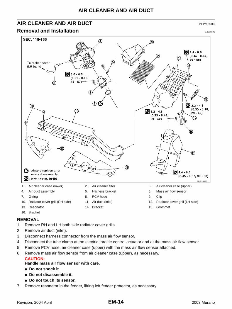
Removal and Installation ABS0033C
REMOVAL1. Remove RH and LH both side radiator cover grills.2. Remove air duct (inlet).3. Disconnect harness connector from the mass air flow sensor.4. Disconnect the tube clamp at the electric throttle control actuator and at the mass air flow sensor.5. Remove PCV hose, air cleaner case (upper) with the mass air flow sensor attached.6. Remove mass air flow sensor from air cleaner case (upper), as necessary.
CAUTION:Handle mass air flow sensor with care.● Do not shock it.● Do not disassemble it.● Do not touch its sensor.
7. Remove resonator in the fender, lifting left fender protector, as necessary.
1. Air cleaner case (lower) 2. Air cleaner filter 3. Air cleaner case (upper)
4. Air duct assembly 5. Harness bracket 6. Mass air flow sensor
7. O-ring 8. PCV hose 9. Clip
10. Radiator cover grill (RH side) 11. Air duct (inlet) 12. Radiator cover grill (LH side)
13. Resonator 14. Bracket 15. Grommet
16. Bracket
PBIC1806E
AIR CLEANER AND AIR DUCT
EM-15
C
D
E
F
G
H
I
J
K
L
M
A
EM
Revision; 2004 April 2003 Murano
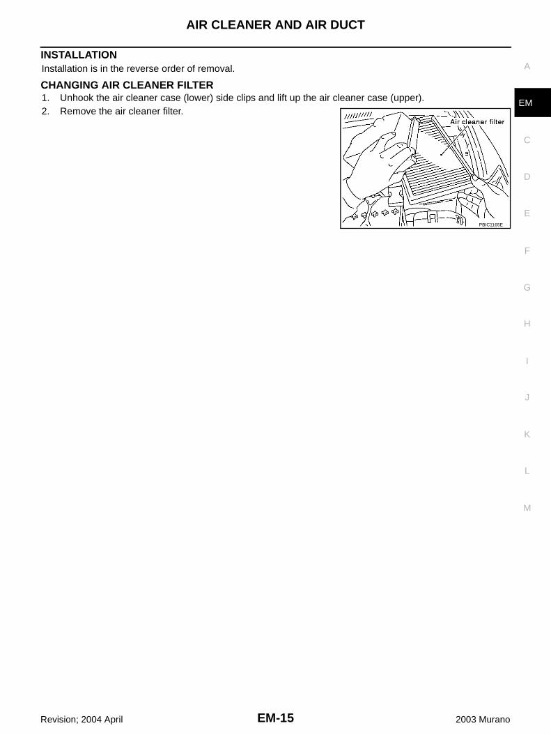
INSTALLATIONInstallation is in the reverse order of removal.
CHANGING AIR CLEANER FILTER1. Unhook the air cleaner case (lower) side clips and lift up the air cleaner case (upper).2. Remove the air cleaner filter.
PBIC1165E
EM-16
INTAKE MANIFOLD COLLECTOR
Revision; 2004 April 2003 Murano
INTAKE MANIFOLD COLLECTOR PFP:14003
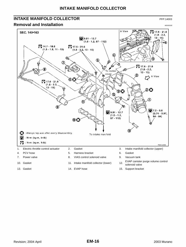
Removal and Installation ABS0032E
1. Electric throttle control actuator 2. Gasket 3. Intake manifold collector (upper)
4. PCV hose 5. Harness bracket 6. Gasket
7. Power valve 8. VIAS control solenoid valve 9. Vacuum tank
10. Gasket 11. Intake manifold collector (lower) 12.EVAP canister purge volume control solenoid valve
13. Gasket 14. EVAP hose 15. Support bracket
PBIC1166E

INTAKE MANIFOLD COLLECTOR
EM-17
C
D
E
F
G
H
I
J
K
L
M
A
EM
Revision; 2004 April 2003 Murano
REMOVALWARNING:To avoid the danger of being scalded, never drain the coolant when the engine is hot.1. Remove engine cover.2. Drain engine coolant, or when water hose is disconnected,
attach plug to prevent engine coolant leakage. Refer to CO-8,"Changing Engine Coolant" .CAUTION:Perform when engine is cold.
3. Remove air duct. Refer to EM-14, "AIR CLEANER AND AIRDUCT" .
4. Remove electric throttle control actuator.● Loosen bolts in the reverse order of that shown in the figure.CAUTION:● Handle carefully to avoid any shock to the electric throt-
tle control actuator.● Do not disassemble.
5. Disconnect vacuum hose and water hose from intake manifold collector (upper and lower).6. Disconnect EVAP canister purge volume control solenoid valve mounting bolt from intake manifold collec-
tor (lower).7. Remove VIAS control solenoid valve and vacuum tank.8. Remove the RH windshield wiper arm and RH front cowl top cover. Refer to EI-21, "COWL TOP" .9. Disconnect the power steering hose bracket.10. Remove intake manifold collector support bracket.11. Remove PCV hose [between intake manifold collector (upper) and RH rocker cover].12. Loosen bolts in reverse order of illustration with power tool, and
remove intake manifold collector (upper and lower) assemblywith power tool.
PBIC1167E
SEM711G
SEM713G

EM-18
INTAKE MANIFOLD COLLECTOR
Revision; 2004 April 2003 Murano
13. Loosen bolts in reverse order of illustration to remove intakemanifold collector (upper) with power tool.
14. Remove power valve in reverse order of illustration.
INSPECTION AFTER REMOVALSurface Distortion● Using straightedge and feeler gauge, inspect the surface distor-
tion of intake manifold collector (lower).
● If it exceeds the limit, replace the intake manifold collector.
INSTALLATION● Install in the reverse order of removal paying attention to the following.
Installation of Power Valve● Tighten in numerical order as shown in the figure.
SEM712G
SEM714G
Limit : 0.1 mm (0.004 in)
PBIC1168E
: 17.6 - 21.6 N·m (1.8 - 2.2 kg-m, 13 - 15 ft-lb)
SEM714G
INTAKE MANIFOLD COLLECTOR
EM-19
C
D
E
F
G
H
I
J
K
L
M
A
EM
Revision; 2004 April 2003 Murano
Installation of Intake Manifold Collector (Upper)● Tighten in numerical order as shown in the figure.
Installation of Intake Manifold Collector (Lower)● Tighten in numerical order as shown in the figure.
NOTE:Tighten mounting bolts to secure gasket (lower), intake manifold col-lector (lower), gasket (upper).
Installation of Electric Throttle Control Actuator ● Install gasket with three protrusions for installation check facing any direction other than upward or down-
ward.● Tighten in numerical order as shown in the figure.
● Perform the “Throttle Valve Closed Position Learning” when har-ness connector of the electric throttle control actuator is discon-nected. Refer to EC-64, "Throttle Valve Closed PositionLearning" .
● Perform the “Idle Air Volume Learning” and “Throttle ValveClosed Position Learning” when the electric throttle control actu-ator is replaced. Refer to EC-64, "Idle Air Volume Learning" .
: 17.6 - 21.6 N·m (1.8 - 2.2 kg-m, 13 - 15 ft-lb)
SEM712G
: 17.6 - 21.6 N·m (1.8 - 2.2 kg-m, 13 - 15 ft-lb)
SEM713G
: 7.2 - 9.6 N·m (0.74 - 0.97 kg-m, 64 - 84 in-lb)
SEM711G

EM-20
INTAKE MANIFOLD
Revision; 2004 April 2003 Murano
INTAKE MANIFOLD PFP:14003
Removal and Installation ABS0033D
REMOVAL1. Release fuel pressure. Refer to EC-66, "FUEL PRESSURE RELEASE" .2. Remove intake manifold collector (upper and lower). Refer to EM-16, "INTAKE MANIFOLD COLLECTOR"
.3. Remove fuel tube and fuel injector assembly. Refer to EM-38, "FUEL INJECTOR AND FUEL TUBE"4. Loosen bolts and nuts in reverse order of illustration to remove
intake manifold assembly with power tool.
INSPECTION AFTER REMOVALSurface Distortion● Using straightedge and feeler gauge, inspect the surface distor-
tion of each surface on intake manifold.
● If it exceeds the limit, replace the intake manifold.
1. Intake manifold 2. Gasket
PBIC1169E
PBIC0778E
Limit : 0.1 mm (0.04 in)
PBIC0870E

INTAKE MANIFOLD
EM-21
C
D
E
F
G
H
I
J
K
L
M
A
EM
Revision; 2004 April 2003 Murano
INSTALLATIONInstall in the reverse order of removal paying attention to the following.
Installation of Intake Manifold● If stud bolts were removed, install them and tighten to the torque
specified below.
● Tighten all mounting bolts and nuts to specified torque in two ormore steps in numerical order shown in figure.
: 9.8 - 11.8 N·m (1.0 - 1.2 kg-m, 87 - 104 in-lb)
1st step: 4.9 - 9.8 N·m (0.5 - 1.0 kg-m, 4 - 7 ft-lb)
2nd step and after: 26.5 - 31.4 N·m (2.7 - 3.2 kg-m, 20 - 23 ft-lb)
PBIC0778E

EM-22
EXHAUST MANIFOLD AND THREE WAY CATALYST
Revision; 2004 April 2003 Murano
EXHAUST MANIFOLD AND THREE WAY CATALYST PFP:14004
Removal and Installation ABS0032G
REMOVALWARNING:● Perform the work when the exhaust and cooling system have completely cooled down.● When removing the engine mounting through bolts and nuts, lift the engine up slightly for safety
with a transmission jack. Refer to EM-95, "ENGINE ASSEMBLY" .1. Remove the exhaust front tube. Refer to EX-3, "Removal and Installation" .2. Remove rear engine mount insulator (2WD models) (when RH exhaust manifold and three way catalyst is
removed). Refer to EM-95, "ENGINE ASSEMBLY" .3. Remove the RH windshield wiper arm and RH front cowl top cover (when RH exhaust manifold and three
way catalyst is removed). Refer to EI-21, "COWL TOP" .
1. Heated oxygen sensor 1 (bank 1) 2. Exhaust manifold cover 3. Exhaust manifold (RH bank)
4. Gasket 5. Gasket 6.Three way catalyst (manifold) (RH bank)
7. Heated oxygen sensor 2 (bank 1) 8. Support (RH) 9. Three way catalyst heat shield
10.Three way catalyst (manifold) (LH bank)
11. Heated oxygen sensor 2 (bank 2) 12. Support (LH)
13. Exhaust manifold cover 14. Exhaust manifold (LH bank) 15. Heated oxygen sensor 1 (bank 2)
PBIC1170E
EXHAUST MANIFOLD AND THREE WAY CATALYST
EM-23
C
D
E
F
G
H
I
J
K
L
M
A
EM
Revision; 2004 April 2003 Murano
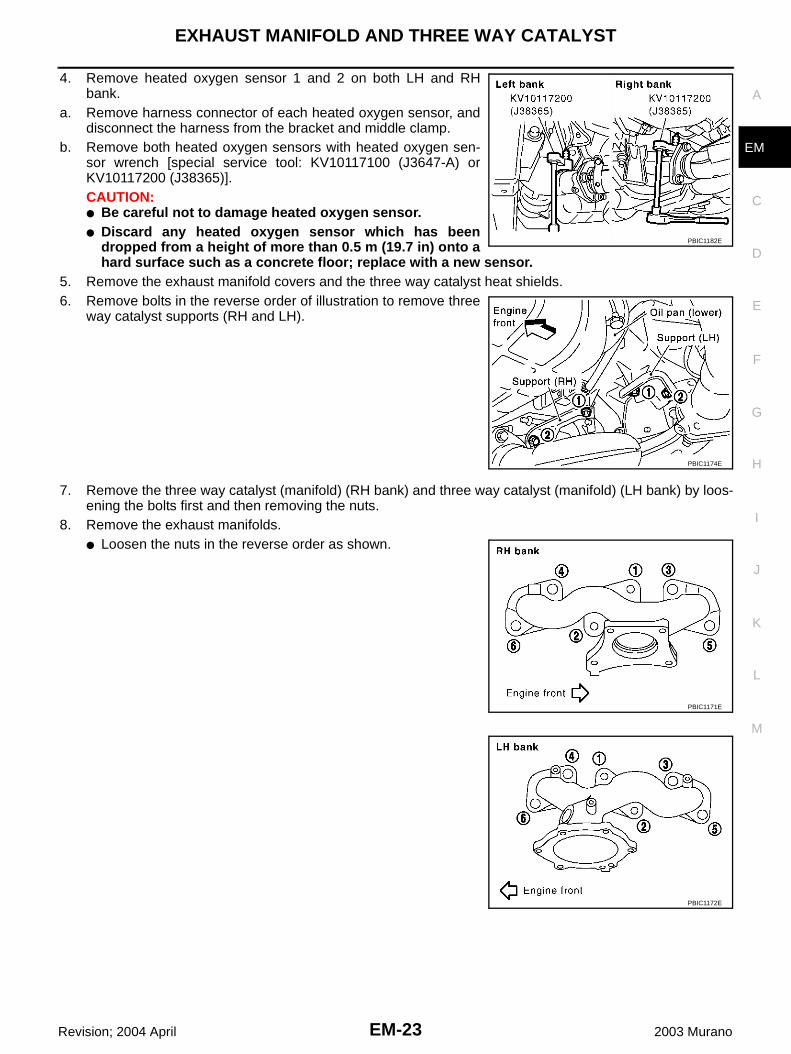
4. Remove heated oxygen sensor 1 and 2 on both LH and RHbank.
a. Remove harness connector of each heated oxygen sensor, anddisconnect the harness from the bracket and middle clamp.
b. Remove both heated oxygen sensors with heated oxygen sen-sor wrench [special service tool: KV10117100 (J3647-A) orKV10117200 (J38365)].CAUTION:● Be careful not to damage heated oxygen sensor.● Discard any heated oxygen sensor which has been
dropped from a height of more than 0.5 m (19.7 in) onto ahard surface such as a concrete floor; replace with a new sensor.
5. Remove the exhaust manifold covers and the three way catalyst heat shields.6. Remove bolts in the reverse order of illustration to remove three
way catalyst supports (RH and LH).
7. Remove the three way catalyst (manifold) (RH bank) and three way catalyst (manifold) (LH bank) by loos-ening the bolts first and then removing the nuts.
8. Remove the exhaust manifolds.● Loosen the nuts in the reverse order as shown.
PBIC1182E
PBIC1174E
PBIC1171E
PBIC1172E

EM-24
EXHAUST MANIFOLD AND THREE WAY CATALYST
Revision; 2004 April 2003 Murano
INSPECTION AFTER REMOVALSurface Distortion● Use a reliable straightedge and feeler gauge to check the flat-
ness of the exhaust manifold mating surfaces.
● If it exceeds the limit, replace the exhaust manifold.
INSTALLATIONInstallation is in the reverse order of removal paying attention to the following.CAUTION:● When using the heated oxygen sensor wrench [special service tool: KV10117200 (J38365)], tighten
to the middle of specified torque range, because the length of the tool may increase the actualtightness. Do not tighten to the maximum specified torque range.
● Before installing a heated oxygen sensor, clean the threads on the exhaust manifold using theoxygen sensor thread cleaner tool (commercial service tool), and apply anti-seize lubricant.
● Do not over-torque the heated oxygen sensors. Doing so may cause damage to the heated oxygensensors.
Exhaust Manifold● Install the exhaust manifold nuts in the numerical order as
shown.
Limit : 0.3 mm (0.012 in)
PBIC1173E
PBIC1171E
PBIC1172E

EXHAUST MANIFOLD AND THREE WAY CATALYST
EM-25
C
D
E
F
G
H
I
J
K
L
M
A
EM
Revision; 2004 April 2003 Murano
Three Way Catalyst SupportsInstall in the numerical order as shown.
: 19 - 25 N·m (2.0 - 2.5 kg-m, 14 - 18 ft-lb)
PBIC1174E
EM-26
OIL PAN AND OIL STRAINER
Revision; 2004 April 2003 Murano
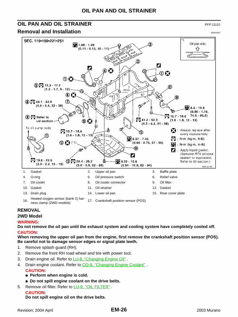
OIL PAN AND OIL STRAINER PFP:11110
Removal and Installation ABS0036T
REMOVAL2WD ModelWARNING:Do not remove the oil pan until the exhaust system and cooling system have completely cooled off.CAUTION:When removing the upper oil pan from the engine, first remove the crankshaft position sensor (POS).Be careful not to damage sensor edges or signal plate teeth.1. Remove splash guard (RH).2. Remove the front RH road wheel and tire with power tool.3. Drain engine oil. Refer to LU-8, "Changing Engine Oil" .4. Drain engine coolant. Refer to CO-8, "Changing Engine Coolant" .
CAUTION:● Perform when engine is cold.● Do not spill engine coolant on the drive belts.
5. Remove oil filter. Refer to LU-9, "OIL FILTER" .CAUTION:Do not spill engine oil on the drive belts.
1. Gasket 2. Upper oil pan 3. Baffle plate
4. O-ring 5. Oil pressure switch 6. Relief valve
7. Oil cooler 8. Oil cooler connector 9. Oil filter
10. Gasket 11. Oil strainer 12. Gasket
13. Drain plug 14. Lower oil pan 15. Rear cover plate
16.Heated oxygen sensor (bank 2) har-ness clamp (2WD models)
17. Crankshaft position sensor (POS)
PBIC1175E

OIL PAN AND OIL STRAINER
EM-27
C
D
E
F
G
H
I
J
K
L
M
A
EM
Revision; 2004 April 2003 Murano
6. Remove oil cooler and water pipes. Refer to LU-10, "OIL COOLER" .7. Remove drive belts. Refer to EM-11, "DRIVE BELTS" .8. Remove A/C compressor with piping connected, and temporarily secure it aside. Refer to ATC-151,
"Components" .9. Remove exhaust front tube. Refer to EX-3, "EXHAUST SYSTEM" .10. Remove the heated oxygen sensor 2 (bank 2) and remove the three way catalyst (manifold) (bank 2) from
the exhaust manifold. Refer to EM-22, "EXHAUST MANIFOLD AND THREE WAY CATALYST" .11. Loosen lower oil pan bolts with power tool in reverse order of
illustration to remove.
12. Insert a seal cutter (special service tool) between the lower oilpan and the upper oil pan.CAUTION:● Be careful not to damage the mating surface.● Do not insert a screwdriver, this will damage the mating
surfaces.
13. Slide seal cutter (special service tool) by tapping on the side ofthe tool with a hammer. Remove lower oil pan.
14. Remove oil strainer.
15. Remove the oil pressure switch. Refer to LU-6, "Inspection" .16. Remove crankshaft position sensor (POS).
PBIC0782E
SEM365E
SEM960F
SEM575GA

EM-28
OIL PAN AND OIL STRAINER
Revision; 2004 April 2003 Murano
CAUTION:● Handle carefully to avoid dropping and shocks.● Do not disassemble.● Do not allow metal powder to adhere to magnetic part at sensor tip.● Do not place sensors in a location where they are exposed to magnetism.
17. Remove the four engine-to-transaxle bolts.
18. Remove upper oil pan.● Loosen bolts in reverse order as shown with power tool.
19. Insert an appropriate size tool into the notch of the upper oil panas shown (1).Pry off the upper oil pan by moving the tool up and down asshown (2).
20. Remove O-rings from the bottom of the cylinder block and oilpump body.
SEM949G
PBIC1636E
SEM155F
PBIC1144E

OIL PAN AND OIL STRAINER
EM-29
C
D
E
F
G
H
I
J
K
L
M
A
EM
Revision; 2004 April 2003 Murano
21. Remove oil pan gaskets.
AWD ModelWARNING:Do not remove the oil pan until the exhaust system and cooling system have completely cooled off.CAUTION:When removing the upper oil pan from the engine, first remove the crankshaft position sensor (POS).Be careful not to damage sensor edges or signal plate teeth.1. Remove engine assembly from vehicle, and separate front suspension member, transaxle and transfer
assembly from engine. Refer to EM-95, "Removal and Installation" .2. Install engine slingers. Refer to EM-100, "CYLINDER BLOCK" .3. install engine sub-attachment to right side of cylinder block, then lift engine, and mount it onto the engine
stand. Refer to EM-100, "CYLINDER BLOCK" .4. Drain engine oil. Refer to LU-8, "Changing Engine Oil" .5. Remove oil filter. Refer to LU-9, "OIL FILTER" .
CAUTION:Do not spill engine oil on the drive belt.
6. Remove oil cooler and water pipes. Refer to LU-10, "OIL COOLER" .7. Remove the heated oxygen sensor 2 (bank 2) and remove the three way catalyst (manifold) (bank 2) from
the exhaust manifold. Refer to EM-22, "EXHAUST MANIFOLD AND THREE WAY CATALYST" .8. Loosen lower oil pan bolts with power tool in reverse order of
illustration to remove.
9. Insert a seal cutter (special service tool) between the lower oilpan and the upper oil pan.CAUTION:● Be careful not to damage the mating surface.● Do not insert a screwdriver, this will damage the mating
surfaces.
PBIC1145E
PBIC0782E
SEM365E

EM-30
OIL PAN AND OIL STRAINER
Revision; 2004 April 2003 Murano
10. Slide seal cutter (special service tool) by tapping on the side ofthe tool with a hammer. Remove lower oil pan.
11. Remove oil strainer.
12. Remove the oil pressure switch. Refer to LU-6, "Inspection" .13. Remove upper oil pan.
● Loosen bolts in reverse order as shown with power tool.
14. Insert an appropriate size tool into the notch of the upper oil panas shown (1).Pry off the upper oil pan by moving the tool up and down asshown (2).
SEM960F
SEM575GA
PBIC1636E
SEM155F

OIL PAN AND OIL STRAINER
EM-31
C
D
E
F
G
H
I
J
K
L
M
A
EM
Revision; 2004 April 2003 Murano
15. Remove O-rings from the bottom of the cylinder block and oilpump body.
16. Remove oil pan gasket.
INSPECTION AFTER REMOVAL● Clean oil strainer if any object attached.
INSTALLATION1. Install in the upper oil pan in the order below.a. Use a scraper to remove old liquid gasket from mating surfaces.
● Also remove the old liquid gasket from mating surface ofthe cylinder block.
● Remove the old liquid gasket from the bolt holes andthreads.
CAUTION:Do not scratch or damage the mating surfaces when clean-ing off the old liquid gasket.
b. Apply Genuine RTV Silicone Sealant or equivalent, to the fronttiming chain case gasket and the rear oil seal retainer gasket asshown. Refer to GI-46, "RECOMMENDED CHEMICAL PROD-UCTS AND SEALANTS" .
PBIC1144E
PBIC1145E
MEM108A
SEM964E

EM-32
OIL PAN AND OIL STRAINER
Revision; 2004 April 2003 Murano
● To install, align protrusion of oil pan gasket with notches offront timing chain case and rear oil seal retainer.
● Install oil pan gasket with smaller arc to front timing chaincase side.
c. Install new O-rings on the cylinder block and oil pump side.
d. Apply a continuous bead of sealant to the cylinder block matingsurface of the upper oil pan to a limited portion as shown.Use Genuine RTV Silicone Sealant or equivalent. Refer toGI-46, "RECOMMENDED CHEMICAL PRODUCTS ANDSEALANTS" .CAUTION:● For bolt holes with marks (5 locations), apply liquid
gasket outside the holes.● Apply a bead of 4.5 to 5.5 mm (0.177 to 0.217 in) diameter
to area “A”.● Attaching should be done within 5 minutes after coating.
e. Install the upper oil pan.● Tighten bolts in numerical order as shown.● There are two types of mounting bolts. Refer to the following
for locating bolts.
f. Install the four engine-to-transaxle bolts. (2WD models)g. Install oil strainer to oil pump.2. Install the lower oil pan in the order below.
PBIC1145E
PBIC1144E
M8 × 100 mm (3.97 in) : 5, 7, 8, 11M8 × 25 mm (0.98 in) : Except the above
KBIA1078E
PBIC1636E

OIL PAN AND OIL STRAINER
EM-33
C
D
E
F
G
H
I
J
K
L
M
A
EM
Revision; 2004 April 2003 Murano
a. Use a scraper to remove old liquid gasket from mating surfaces.● Also remove old liquid gasket from mating surface of
upper oil pan.
b. Apply a continuous bead of sealant to the lower oil pan.● Use Genuine RTV Silicone Sealant or equivalent. Refer to
GI-46, "RECOMMENDED CHEMICAL PRODUCTS ANDSEALANTS" .
● Be sure the sealant is 4.5 - 5.5 mm (0.177 - 0.217 in) wide.● Attaching should be done within 5 minutes after coating.
c. Install lower oil pan.● Tighten the bolts in the numerical order as shown.
3. Install oil pan drain plug.● Refer to illustration of components of former page for installation direction of washer.
4. Install in the reverse order of removal after this step.At least 30 minutes after oil pan is installed, pour engine oil.
SEM958F
PBIC1146E
PBIC0782E

EM-34
OIL PAN AND OIL STRAINER
Revision; 2004 April 2003 Murano
INSPECTION AFTER INSTALLATION● Before starting engine, check the levels of engine coolant, engine oil and working fluid. If less than
required quantity, fill to the specified level.● Use procedure below to check for fuel leakage.– Turn ignition switch ON (with engine stopped). With fuel pressure applied to fuel piping, check for fuel
leakage at connection points.– Start engine. With engine speed increased, check again for fuel leakage at connection points.● Run engine to check for unusual noise and vibration.● Warm up engine thoroughly to make sure there is no leakage of engine coolant, engine oil and working
fluid, fuel and exhaust gas.● Bleed air from passages in pipes and tubes of applicable lines, such as in cooling system.● After cooling down engine, again check amounts of engine coolant, engine oil and working fluid. Refill to
specified level, if necessary.

IGNITION COIL
EM-35
C
D
E
F
G
H
I
J
K
L
M
A
EM
Revision; 2004 April 2003 Murano
IGNITION COIL PFP:22448
Removal and Installation ABS0032I
REMOVAL1. Remove the engine cover. Refer to EM-16, "INTAKE MANIFOLD COLLECTOR" .2. Disconnect the mass air flow sensor electrical connector and remove the air cleaner and air duct assem-
bly. Refer to EM-14, "Removal and Installation" .3. Remove the RH windshield wiper arm and the RH front cowl top cover. Refer to EI-21, "COWL TOP" .4. Remove the intake manifold collector (upper and lower), gasket, and electric throttle control actuator.
Refer to EM-16, "Removal and Installation" .The intake manifold collector (upper) should be moved aside with water hoses connected.
5. Remove ignition coil.
INSTALLATION1. Installation is in the reverse order of removal.
1. Ignition coil 2. Spark plug 3. Rocker cover (left bank)
PBIC1176E

EM-36
SPARK PLUG (PLATINUM-TIPPED TYPE)
Revision; 2004 April 2003 Murano
SPARK PLUG (PLATINUM-TIPPED TYPE) PFP:22401
Removal and Installation ABS0033P
REMOVAL1. Remove engine cover. Refer to EM-16, "INTAKE MANIFOLD COLLECTOR" .2. Remove ignition coil. Refer to EM-35, "IGNITION COIL" .3. Remove spark plug using spark plug wrench (commercial ser-
vice tool).
INSPECTION AFTER REMOVAL● Use standard type spark plug for normal condition.The hot type spark plug is suitable when fouling occurs with the standard type spark plug under conditionssuch as:● Frequent engine starts● Low ambient temperaturesThe cold type spark plug is suitable when spark plug knock occurs with the standard type spark plug underconditions such as:● Extended highway driving● Frequent high engine revolution
CAUTION:● Do not drop or shock spark plug.● Do not use a wire brush for cleaning.● If plug tip is covered with carbon, spark plug cleaner may
be used.
SEM294A
Make NGK
Standard type PLFR5A-11
Hot type PLFR4A-11
Cold type PLFR6A-11
Gap (Nominal) : 1.1 mm (0.043 in)
Cleaner air pressure:
Less than 588 kPa (6 kg/cm2 , 85 psi)Cleaning time:
Less than 20 seconds
SMA773C

SPARK PLUG (PLATINUM-TIPPED TYPE)
EM-37
C
D
E
F
G
H
I
J
K
L
M
A
EM
Revision; 2004 April 2003 Murano
● Checking and adjusting plug gap is not required betweenchange intervals.
INSTALLATION● Install in the reverse order of removal.
SMA806CA

EM-38
FUEL INJECTOR AND FUEL TUBE
Revision; 2004 April 2003 Murano
FUEL INJECTOR AND FUEL TUBE PFP:16600
Removal and Installation ABS0032K
CAUTION:Do not remove or disassemble parts unless instructed as shown in the figure.
REMOVALWARNING:To avoid the danger of being scalded, never drain the engine coolant when the engine is hot.1. Remove the engine cover. Refer to EM-16, "INTAKE MANIFOLD COLLECTOR" .2. Release the fuel pressure. Refer to EC-66, "FUEL PRESSURE RELEASE" .3. Remove the RH windshield wiper arm and the RH cowl top cover. Refer toEI-21, "Removal and Installa-
tion" .4. Remove radiator cover grille, air duct (inlet), air cleaner case, air duct assembly and mass air flow sensor.
Refer to EM-14, "AIR CLEANER AND AIR DUCT" .5. Disconnect electric throttle control actuator and engine coolant hoses.
CAUTION:Handle carefully to avoid any shock to the electric throttle control actuator.
6. Disconnect vacuum hose, fuel injectors electrical connectors, and PCV hose.CAUTION:Cover any engine openings to avoid the entry of any foreign material.
7. Remove the vacuum tank from intake manifold collector (lower).8. Disconnect the power steering hose bracket.
1. Fuel tube 2. Insulator 3. Clip
4. O-ring (black) 5. Fuel injector 6. O-ring (green)
7. Fuel damper 8. O-ring 9. Fuel feed hose (with damper)
10. Quick connector 11. Quick connector cap
PBIC1177E
FUEL INJECTOR AND FUEL TUBE
EM-39
C
D
E
F
G
H
I
J
K
L
M
A
EM
Revision; 2004 April 2003 Murano
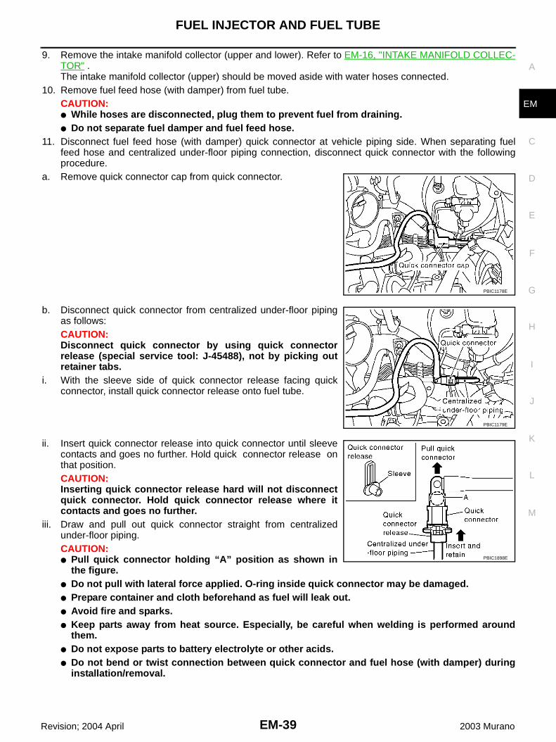
9. Remove the intake manifold collector (upper and lower). Refer to EM-16, "INTAKE MANIFOLD COLLEC-TOR" .The intake manifold collector (upper) should be moved aside with water hoses connected.
10. Remove fuel feed hose (with damper) from fuel tube.CAUTION:● While hoses are disconnected, plug them to prevent fuel from draining.● Do not separate fuel damper and fuel feed hose.
11. Disconnect fuel feed hose (with damper) quick connector at vehicle piping side. When separating fuelfeed hose and centralized under-floor piping connection, disconnect quick connector with the followingprocedure.
a. Remove quick connector cap from quick connector.
b. Disconnect quick connector from centralized under-floor pipingas follows:CAUTION:Disconnect quick connector by using quick connectorrelease (special service tool: J-45488), not by picking outretainer tabs.
i. With the sleeve side of quick connector release facing quickconnector, install quick connector release onto fuel tube.
ii. Insert quick connector release into quick connector until sleevecontacts and goes no further. Hold quick connector release onthat position.CAUTION:Inserting quick connector release hard will not disconnectquick connector. Hold quick connector release where itcontacts and goes no further.
iii. Draw and pull out quick connector straight from centralizedunder-floor piping.CAUTION:● Pull quick connector holding “A” position as shown in
the figure.● Do not pull with lateral force applied. O-ring inside quick connector may be damaged.● Prepare container and cloth beforehand as fuel will leak out.● Avoid fire and sparks.● Keep parts away from heat source. Especially, be careful when welding is performed around
them.● Do not expose parts to battery electrolyte or other acids.● Do not bend or twist connection between quick connector and fuel hose (with damper) during
installation/removal.
PBIC1178E
PBIC1179E
PBIC1898E
EM-40
FUEL INJECTOR AND FUEL TUBE
Revision; 2004 April 2003 Murano
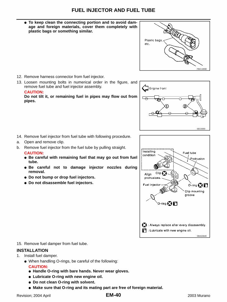
● To keep clean the connecting portion and to avoid dam-age and foreign materials, cover them completely withplastic bags or something similar.
12. Remove harness connector from fuel injector.13. Loosen mounting bolts in numerical order in the figure, and
remove fuel tube and fuel injector assembly.CAUTION:Do not tilt it, or remaining fuel in pipes may flow out frompipes.
14. Remove fuel injector from fuel tube with following procedure.a. Open and remove clip.b. Remove fuel injector from the fuel tube by pulling straight.
CAUTION:● Be careful with remaining fuel that may go out from fuel
tube.● Be careful not to damage injector nozzles during
removal.● Do not bump or drop fuel injectors.● Do not disassemble fuel injectors.
15. Remove fuel damper from fuel tube.
INSTALLATION1. Install fuel damper.
● When handling O-rings, be careful of the following:CAUTION:● Handle O-ring with bare hands. Never wear gloves.● Lubricate O-ring with new engine oil.● Do not clean O-ring with solvent.● Make sure that O-ring and its mating part are free of foreign material.
PBIC1899E
SEC030D
SBIA0364E

FUEL INJECTOR AND FUEL TUBE
EM-41
C
D
E
F
G
H
I
J
K
L
M
A
EM
Revision; 2004 April 2003 Murano
● When installing O-ring, be careful not to scratch it with tool or fingernails. Also be careful notto twist or stretch O-ring. If O-ring was stretched while it was being attached, do not insert itquickly into fuel tube.
● Insert fuel damper straight into fuel tube.● Tighten mounting bolts evenly in turn.● After tightening mounting bolts, make sure that there is no gap between flange and fuel tube.
2. Install O-rings to fuel injector paying attention to the items below.CAUTION:● Upper and lower O-ring are different. Be careful not to confuse them.
● Handle O-ring with bare hands. Never wear gloves.● Lubricate O-ring with new engine oil.● Do not clean O-ring with solvent.● Make sure that O-ring and its mating part are free of foreign material.● When installing O-ring, be careful not to scratch it with tool or fingernails. Also be careful not to
twist or stretch O-ring. If O-ring was stretched while it was being attached, do not insert itquickly into fuel tube.
● Insert O-ring straight into fuel tube. Do not decenter or twist it.3. Install fuel injector to fuel tube with the following procedure.a. Insert clip into clip mounting groove on fuel injector.
● Insert clip so that lug “A” of fuel injector matches notch “A” ofthe clip.CAUTION:● Do not reuse clip. Replace it with a new one.● Be careful to keep clip from interfering with O-ring. If
interference occurs, replace O-ring.b. Insert fuel injector into fuel tube with clip attached.
● Insert it while matching it to the axial center.● Insert fuel injector so that lug “B” of fuel tube matches notch
“B” of the clip.● Make sure that fuel tube flange is securely fixed in flange fix-
ing groove on clip.c. Make sure that installation is complete by checking that fuel
injector does not rotate or come off.
4. Tighten mounting bolts in two steps in numerical order shown infigure.
CAUTION:Be careful not to let tip of injector nozzle come in contactwith other parts.
5. Connect fuel injector harness.6. Install intake manifold collector (upper and lower). Refer to EM-
16, "INTAKE MANIFOLD COLLECTOR" .
Fuel tube side : BlackNozzle side : Green
PBIC1021E
1st step : 9.3 - 10.8 N·m (0.95 - 1.1 kg-m, 6.9 - 7.9 ft-lb)
2nd step : 20.6 - 26.5 N·m (2.1 - 2.7 kg-m, 16 - 19 ft-lb)
SEC999C

EM-42
FUEL INJECTOR AND FUEL TUBE
Revision; 2004 April 2003 Murano
7. Connect quick connector between fuel feed hose (with damper)and centralized under-floor piping connection with the followingprocedure:
a. Check the connection for damage and foreign materials.b. Align the quick connector with the tube, then insert the connec-
tor straight into the tube until a click is heard.c. After connecting the quick connector, use the following method
to make sure it is full connected.● Visually confirm that the two retainer tabs are connected to
the connector.● Pull the tube and the connector to make sure they are
securely connected.d. Install quick connector cap to quick connector connection.
● Install quick connector cap with arrow on surface facing indirection of quick connector.
CAUTION:If cap cannot be installed smoothly, quick connector mayhave not been installed correctly. Check connection again.
8. Install in the reverse order of removal after this step.
INSPECTION AFTER INSTALLATIONCheck on Fuel Leakage1. Turn ignition switch ON (with engine stopped). With fuel pressure applied to fuel piping, check for fuel
leakage at connection points.2. Start engine. With engine speed increased, check again for fuel leakage at connection points.NOTE:Use mirrors for checking at points out of clear sight.CAUTION:Do not touch the engine immediately after stopped, as engine becomes extremely hot.
PBIC1180E
PBIC1181E

ROCKER COVER
EM-43
C
D
E
F
G
H
I
J
K
L
M
A
EM
Revision; 2004 April 2003 Murano
ROCKER COVER PFP:13264
Removal and Installation ABS0034R
REMOVAL1. Remove the intake manifold collector (upper and lower) with power tool. Refer to EM-16, "INTAKE MANI-
FOLD COLLECTOR" .2. Remove the ignition coil. Refer to EM-35, "IGNITION COIL" .3. Remove PCV hoses from rocker covers.
1. PCV hose 2. Oil filler cap 3. Rocker cover (RH bank)
4. PCV valve 5. O-ring 6. Rocker cover gasket
7. Rocker cover (LH bank)
PBIC1183E

EM-44
ROCKER COVER
Revision; 2004 April 2003 Murano
4. Loosen bolts in the reverse order shown in the figure (withpower tool).
INSTALLATION1. Apply liquid gasket of 3.0 mm (0.12 in) diameter to position
shown in the figure (both edges of No.1 camshaft bracket) (onboth banks).● First, apply it to engine longitudinal direction [5.0 mm (0.197
in) + 5.0 mm (0.197 in) side in figure].● Use Genuine Thread Sealant or equivalent. Refer to GI-46,
"RECOMMENDED CHEMICAL PRODUCTS AND SEAL-ANTS" .
2. Install rocker cover.● Check if rocker cover gasket is dropped from installation groove of rocker cover.
PBIC1184E
PBIC0786E

ROCKER COVER
EM-45
C
D
E
F
G
H
I
J
K
L
M
A
EM
Revision; 2004 April 2003 Murano
3. Tighten bolts two steps separately in order numbers in illustra-tion.
4. Install PCV hose.● Insert PCV hose by 25 to 30 mm (0.98 to 1.18 in) from connector end.● When installing, be careful not to twist or come in contact with other parts.● Install PCV hose between right and left rocker covers with its identification paint facing upward (right
rocker cover side).5. Install in the reverse order of removal after this step.
1st step: 0.96 - 2.96 N·m (0.10 - 0.30 kg-m, 9 - 26 in-lb)
2nd step: 7.33 - 9.33 N·m (0.75 - 0.95 kg-m, 65 - 82 in-lb)
PBIC1184E

EM-46
FRONT TIMING CHAIN CASE
Revision; 2004 April 2003 Murano
FRONT TIMING CHAIN CASE PFP:13599
Removal and Installation ABS0032M
NOTE:● This section describes removal/installation procedure of front timing chain case and timing chain related
parts without removing upper oil pan on vehicle.● When upper oil pan needs to be removed or installed, or when rear timing chain case is removed or
installed, remove lower and upper oil pans first. Then remove front timing chain case, timing chain relatedparts, and rear timing chain case in this order, and install in reverse order of removal. Refer to EM-54,"TIMING CHAIN" .
● Refer to EM-54, "TIMING CHAIN" for component parts location.
REMOVAL1. Place vehicle onto lift.2. Disconnect battery ground cable.3. Remove engine cover. Refer to EM-16, "INTAKE MANIFOLD COLLECTOR" .4. Remove radiator cover grilles, air duct (inlet), air cleaner case assembly and air duct. Refer to EM-14,
"AIR CLEANER AND AIR DUCT" .5. Remove RH and LH rocker covers. Refer to EM-43, "ROCKER COVER" .
NOTE:When only primary timing chain is removed, rocker cover does not need to be removed.
6. Remove splash guard (RH).7. Drain engine coolant from radiator. Refer to CO-8, "Changing Engine Coolant" .8. Drain engine oil. Refer to LU-8, "Changing Engine Oil" .9. Remove engine harnesses.10. Remove A/C compressor from bracket with piping connected, and temporarily secure it aside. Refer to
ATC-152, "Removal and Installation of Compressor" .11. Remove power steering oil pump from bracket with piping connected, and temporarily secure it aside.
Refer to PS-28, "Removal and Installation" .12. Remove power steering oil pump bracket. Refer to PS-28, "Removal and Installation" .13. Remove alternator. Refer to SC-27, "Removal and Installation" .14. Remove idler pulley and bracket. Refer to EM-54, "TIMING CHAIN" .15. Obtain compression TDC of No.1 cylinder as follows:
NOTE:When timing chain is not removed/installed, this step is notrequired.
a. Rotate crankshaft pulley clockwise to align timing mark (groovedline without color) with timing indicator.
b. Check that intake and exhaust cam noses on No. 1 cylinder(engine front side of RH bank) are located as shown.● If not, turn the crankshaft one revolution (360°) and align as
shown.NOTE:When only primary timing chain is removed, rocker cover doesnot need to be removed. To confirm that No. 1 cylinder is at itscompression TDC, remove front timing chain case first. Thencheck mating marks on camshaft sprockets. Refer to EM-54,"TIMING CHAIN" .
SEM918G
SEM418G

FRONT TIMING CHAIN CASE
EM-47
C
D
E
F
G
H
I
J
K
L
M
A
EM
Revision; 2004 April 2003 Murano
16. Loosen crankshaft pulley bolt. (At this time remove oil pan rearcover plate and set a suitable tool to ring gear so that crankshaftcannot rotate.)CAUTION:Exercise care not to damage signal plate.
17. Remove crankshaft pulley with a suitable puller.18. Remove lower oil pan. Refer to EM-26, "OIL PAN AND OIL
STRAINER" .
19. Loosen bolts in reverse order shown in figure, and removeinstallation bolts at the front of upper oil pan.
20. Install lower oil pan temporarily.21. Support the lower oil pan bottom with a transmission jack.
● Perform following operations with engine front-side supportedwith jack.
22. Remove the RH and LH intake valve timing control covers.● Loosen bolts in reverse order as shown.● Use seal cutter [special service tool: KV10111100 (J37228)]
or an equivalent tool to cut liquid gasket for removal.CAUTION:Shaft is internally jointed with intake camshaft sprocketcenter hole. When removing, keep it horizontal until it iscompletely disconnected.
SEM965F
SEM915E
PBIC1637E
SEM728G

EM-48
FRONT TIMING CHAIN CASE
Revision; 2004 April 2003 Murano
23. Remove right side engine mounting, mounting bracket and nuts. Refer to EM-95, "ENGINE ASSEMBLY" .24. Raise engine front-side with jack. (This secures workspace to remove front timing chain case.)25. Remove front timing chain case.a. Loosen mounting bolts in reverse order as shown.
b. Insert the appropriate size tool into the notch at the top of thefront timing chain case as shown (1).
c. Pry off the case by moving the tool as shown (2).● Use seal cutter [special service tool: KV10111100 (J37228)]
or an equivalent tool to cut liquid gasket for removal. CAUTION:● Do not use screwdrivers or something similar.● After removal, handle it carefully so it does not tilt, cant,
or warp under a load.
26. Remove water pump cover and chain tensioner cover from front timing chain case. ● Use seal cutter [special service tool: KV10111100 (J37228)] or an equivalent tool to cut liquid gasket for
removal. 27. Remove the front oil seal from the front timing chain case using
a suitable tool.● Use screwdriver for removal.● Exercise care not to damage front timing chain case.
28. Remove timing chain and related parts. Refer to EM-54, "TIMING CHAIN" starting from step 11. (Disre-gard the procedures for removing front timing chain case and upper oil pan.)
29. Remove residual gasket from front timing chain case and liquid gasket mating surface.CAUTION:Be careful not to allow gasket fragments to enter oil pan.
INSTALLATION1. Install timing chain and related parts. Refer to EM-54, "TIMING CHAIN" .
SEM730G
SEM156F
EMQ0032D
FRONT TIMING CHAIN CASE
EM-49
C
D
E
F
G
H
I
J
K
L
M
A
EM
Revision; 2004 April 2003 Murano
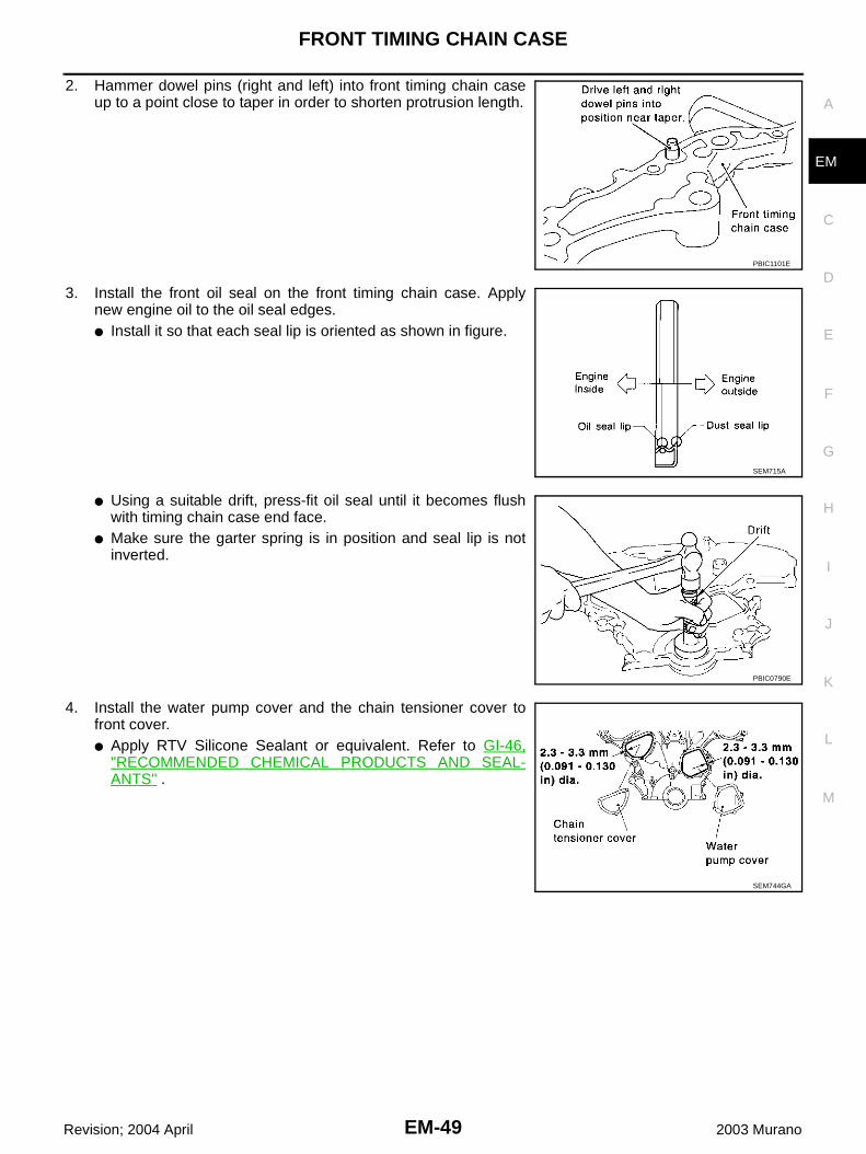
2. Hammer dowel pins (right and left) into front timing chain caseup to a point close to taper in order to shorten protrusion length.
3. Install the front oil seal on the front timing chain case. Applynew engine oil to the oil seal edges.● Install it so that each seal lip is oriented as shown in figure.
● Using a suitable drift, press-fit oil seal until it becomes flushwith timing chain case end face.
● Make sure the garter spring is in position and seal lip is notinverted.
4. Install the water pump cover and the chain tensioner cover tofront cover.● Apply RTV Silicone Sealant or equivalent. Refer to GI-46,
"RECOMMENDED CHEMICAL PRODUCTS AND SEAL-ANTS" .
PBIC1101E
SEM715A
PBIC0790E
SEM744GA
EM-50
FRONT TIMING CHAIN CASE
Revision; 2004 April 2003 Murano
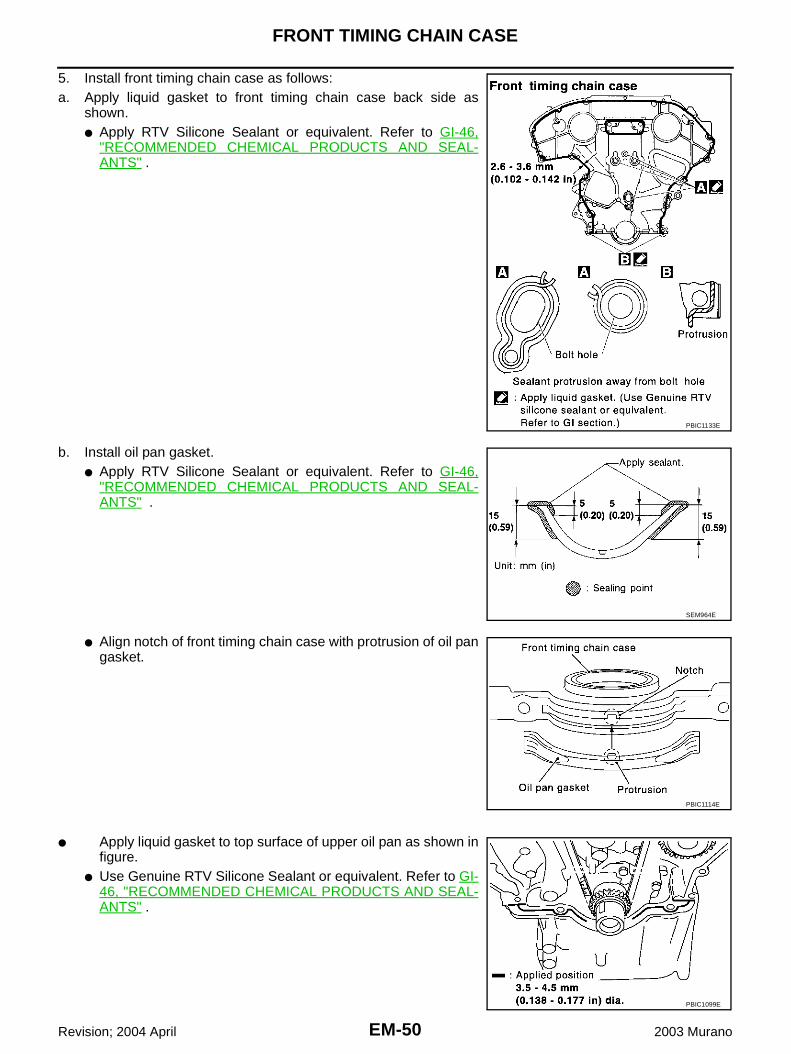
5. Install front timing chain case as follows:a. Apply liquid gasket to front timing chain case back side as
shown.● Apply RTV Silicone Sealant or equivalent. Refer to GI-46,
"RECOMMENDED CHEMICAL PRODUCTS AND SEAL-ANTS" .
b. Install oil pan gasket.● Apply RTV Silicone Sealant or equivalent. Refer to GI-46,
"RECOMMENDED CHEMICAL PRODUCTS AND SEAL-ANTS" .
● Align notch of front timing chain case with protrusion of oil pangasket.
● Apply liquid gasket to top surface of upper oil pan as shown infigure.
● Use Genuine RTV Silicone Sealant or equivalent. Refer to GI-46, "RECOMMENDED CHEMICAL PRODUCTS AND SEAL-ANTS" .
PBIC1133E
SEM964E
PBIC1114E
PBIC1099E
FRONT TIMING CHAIN CASE
EM-51
C
D
E
F
G
H
I
J
K
L
M
A
EM
Revision; 2004 April 2003 Murano
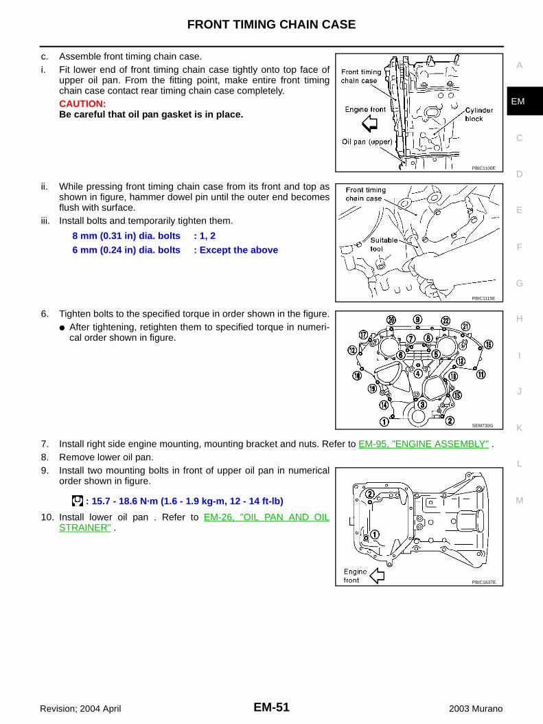
c. Assemble front timing chain case.i. Fit lower end of front timing chain case tightly onto top face of
upper oil pan. From the fitting point, make entire front timingchain case contact rear timing chain case completely.CAUTION:Be careful that oil pan gasket is in place.
ii. While pressing front timing chain case from its front and top asshown in figure, hammer dowel pin until the outer end becomesflush with surface.
iii. Install bolts and temporarily tighten them.
6. Tighten bolts to the specified torque in order shown in the figure.● After tightening, retighten them to specified torque in numeri-
cal order shown in figure.
7. Install right side engine mounting, mounting bracket and nuts. Refer to EM-95, "ENGINE ASSEMBLY" .8. Remove lower oil pan.9. Install two mounting bolts in front of upper oil pan in numerical
order shown in figure.
10. Install lower oil pan . Refer to EM-26, "OIL PAN AND OILSTRAINER" .
PBIC1100E
8 mm (0.31 in) dia. bolts : 1, 26 mm (0.24 in) dia. bolts : Except the above
PBIC1115E
SEM730G
: 15.7 - 18.6 N·m (1.6 - 1.9 kg-m, 12 - 14 ft-lb)
PBIC1637E
EM-52
FRONT TIMING CHAIN CASE
Revision; 2004 April 2003 Murano
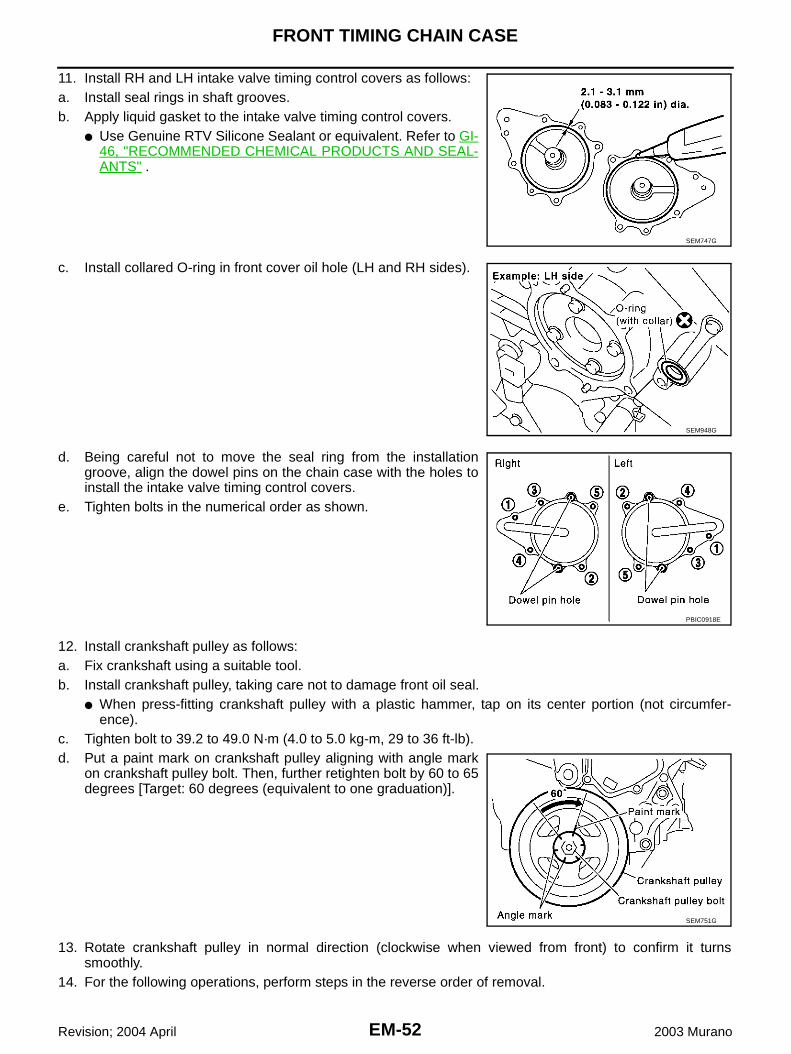
11. Install RH and LH intake valve timing control covers as follows:a. Install seal rings in shaft grooves.b. Apply liquid gasket to the intake valve timing control covers.
● Use Genuine RTV Silicone Sealant or equivalent. Refer to GI-46, "RECOMMENDED CHEMICAL PRODUCTS AND SEAL-ANTS" .
c. Install collared O-ring in front cover oil hole (LH and RH sides).
d. Being careful not to move the seal ring from the installationgroove, align the dowel pins on the chain case with the holes toinstall the intake valve timing control covers.
e. Tighten bolts in the numerical order as shown.
12. Install crankshaft pulley as follows:a. Fix crankshaft using a suitable tool.b. Install crankshaft pulley, taking care not to damage front oil seal.
● When press-fitting crankshaft pulley with a plastic hammer, tap on its center portion (not circumfer-ence).
c. Tighten bolt to 39.2 to 49.0 N·m (4.0 to 5.0 kg-m, 29 to 36 ft-lb).d. Put a paint mark on crankshaft pulley aligning with angle mark
on crankshaft pulley bolt. Then, further retighten bolt by 60 to 65degrees [Target: 60 degrees (equivalent to one graduation)].
13. Rotate crankshaft pulley in normal direction (clockwise when viewed from front) to confirm it turnssmoothly.
14. For the following operations, perform steps in the reverse order of removal.
SEM747G
SEM948G
PBIC0918E
SEM751G

FRONT TIMING CHAIN CASE
EM-53
C
D
E
F
G
H
I
J
K
L
M
A
EM
Revision; 2004 April 2003 Murano
NOTE:If hydraulic pressure inside chain tensioner drops after removal/installation, slack in the guide may gener-ate a pounding noise during and just after engine start. However, this is normal. Noise will stop afterhydraulic pressure rises.
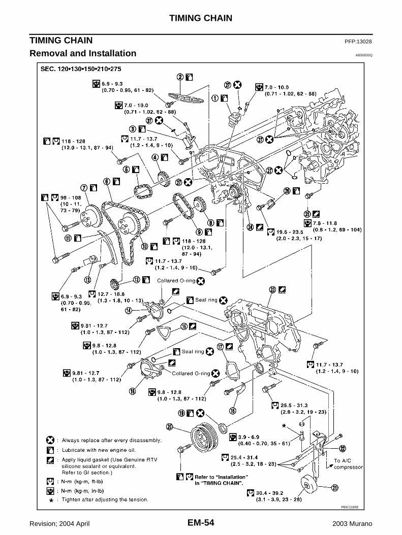
EM-54
TIMING CHAIN
Revision; 2004 April 2003 Murano
TIMING CHAIN PFP:13028
Removal and Installation ABS0033Q
PBIC1185E

TIMING CHAIN
EM-55
C
D
E
F
G
H
I
J
K
L
M
A
EM
Revision; 2004 April 2003 Murano
CAUTION:● When installing camshafts, chain tensioners, oil seals, or other sliding parts, lubricate contacting
surfaces with new engine oil.● Apply new engine oil to bolt threads and seat surfaces when installing camshaft sprockets, cam-
shaft brackets, and crankshaft pulley.NOTE:● This section describes procedures for removing/installing front timing chain case and timing chain related
parts, and rear timing chain case, when oil pan (upper) needs to be removed/installed for engine overhaul,etc.
● To remove/install front timing chain case, timing chain, and its related parts without removing oil pan(upper), refer to EM-46, "FRONT TIMING CHAIN CASE" .
REMOVAL1. Remove engine assembly from vehicle, and separate front suspension member, transaxle and transfer
(AWD models) assembly from engine. Refer to EM-95, "Removal and Installation" .2. Install engine slingers. Refer to EM-95, "ENGINE ASSEMBLY" .3. Install engine sub-attachment to right side of cylinder block, then lift engine, and mount it onto the engine
stand. Refer to EM-100, "CYLINDER BLOCK" .4. Drain engine oil. Refer to LU-8, "Changing Engine Oil" .5. Remove engine harnesses.6. Remove water hoses.7. Remove EVAP canister purge volume control solenoid valve. Refer to EM-16, "INTAKE MANIFOLD COL-
LECTOR" .8. Remove drive belts and idler pulley bracket.9. Remove power steering oil pump assembly. Refer to PS-28, "Removal and Installation" .10. Remove alternator. Refer to SC-27, "Removal and Installation" .11. Remove RH and LH rocker covers with power tool. Refer to EM-43, "ROCKER COVER" .12. Remove crankshaft position sensor (POS).
CAUTION:● Handle carefully to avoid dropping and shocks.● Do not disassemble.● Do not allow metal powder to adhere to magnetic part at sensor tip.● Do not place sensors in a location where they are exposed to magnetism.
13. Obtain compression TDC of No.1 cylinder as follows:NOTE:When timing chain is not removed/installed, this step is notrequired.
a. Rotate crankshaft pulley clockwise to align timing mark (groovedline without color) with timing indicator.
1. Timing chain tensioner (secondary) 2. Internal chain guide 3. Timing chain tensioner (secondary)
4. Camshaft sprocket (EXH) 5. Timing chain (secondary) 6. Timing chain (primary)
7. Camshaft sprocket (INT) 8. Camshaft sprocket (EXH) 9. Timing chain (secondary)
10. Camshaft sprocket (INT) 11. Slack guide 12. Crankshaft sprocket
13. Timing chain tensioner (primary) 14. Intake valve timing control cover 15. Chain tensioner cover
16. Water hose clamp 17. Water pump cover 18. Intake valve timing control cover
19. Front oil seal 20. Crankshaft pulley 21. Idler pulley
22. Idler pulley bracket 23. Front timing chain case 24. Rear timing chain case
25. Water drain plug 26. Tension guide 27. O-ring
SEM918G

EM-56
TIMING CHAIN
Revision; 2004 April 2003 Murano
14. Remove lower and upper oil pans. Refer to EM-26, "OIL PAN AND OIL STRAINER" .15. Remove crankshaft pulley as follows:a. Lock crankshaft with a hammer handle or similar tool to loosen fixing bolts.b. Remove crankshaft pulley with a suitable puller.
16. Remove the RH and LH intake valve timing control covers.● Loosen bolts in reverse order as shown.● Use seal cutter [special service tool: KV10111100 (j37228)] or
an equivalent tool to cut liquid gasket for removal.CAUTION:Shaft is internally jointed with intake camshaft sprocketcenter hole. When removing, keep it horizontal until it iscompletely disconnected.
17. Remove RH engine mounting bracket. Refer to EM-95, "ENGINE ASSEMBLY" .18. Remove front timing chain case.a. Loosen mounting bolts in reverse order as shown.
b. Insert the appropriate size tool into the notch at the top of thefront timing chain case as shown (1).
c. Pry off the case by moving the tool as shown (2).● Use seal cutter [special service tool: KV10111100 (J37228)]
or an equivalent tool to cut liquid gasket for removal. CAUTION:● Do not use screwdrivers or something similar.● After removal, handle it carefully so it does not tilt, cant,
or warp under a load.
19. Remove water pump cover and chain tensioner cover from front timing chain case. ● Use seal cutter [special service tool: KV10111100 (J37228)] or an equivalent tool to cut liquid gasket for
removal. 20. Remove the front oil seal from the front timing chain case using
a suitable tool.● Use screwdriver for removal.● Exercise care not to damage front timing chain case.
SEM728G
SEM730G
SEM156F
EMQ0032D

TIMING CHAIN
EM-57
C
D
E
F
G
H
I
J
K
L
M
A
EM
Revision; 2004 April 2003 Murano
21. Remove internal chain guide, timing chain tensioner, tensionguide and slack guide.
● Remove timing chain tensioner as follows:a. Pull lever down and release plunger stopper tab.
● Plunger stopper tab can be pushed up to release (coaxialstructure with lever).
b. Insert stopper pin into tensioner body hole to hold lever, andkeep the tab released.NOTE: An Allen wrench [2.5 mm (0.098 in)] is used for a stopper pin asan example.
c. Insert plunger into tensioner body by pressing the slack guide.d. Keep the slack guide pressed and hold it by pushing the stopper
pin through the lever hole and body hole.e. Remove the mounting bolts and remove the timing chain ten-
sioner.
22. Remove timing chain (primary) and crankshaft sprocket.CAUTION:● After removing timing chain, do not turn the crankshaft and camshaft separately, or the valves
will strike the piston heads.
SEM731G
SEM732G
SEM733G

EM-58
TIMING CHAIN
Revision; 2004 April 2003 Murano
23. Attach a suitable stopper pin to the RH and LH camshaft chaintensioners (for secondary timing chains).NOTE:For removal and installation of secondary chain tensioner, referto EM-70, "CAMSHAFT" . (Removing No. 1 camshaft bracket isrequired.)
24. Remove intake and exhaust camshaft sprocket bolts.● Apply paint to timing chain and camshaft sprockets for align-
ment during installation.● Secure the hexagonal portion of the camshaft using a wrench
to loosen the mounting bolts.
25. Remove secondary timing chain together with camshaft sprock-ets.● Turn camshaft slightly to secure slackness of timing chain on
chain tensioner side.● Insert 0.5 mm (0.020 in) thick metal or resin plate between
timing chain and chain tensioner plunger (guide). Removesecondary timing chain together with camshaft sprockets withtiming chain loose from guide groove.CAUTION:Be careful of plunger coming-off when removing timingchain. This is because plunger of chain tensioner movesduring operation, leading to coming-off of fixed stopperpin. NOTE:Camshaft sprocket (INT) is two-for-one structure of primary and secondary sprockets.
● When handling camshaft sprocket (INT), be careful of the fol-lowing:CAUTION:● Handle carefully to avoid any shock to camshaft
sprocket.● Do not disassemble. (Never loosen bolts “A” and “B”
as shown).
26. Remove chain tension guide.
SEM923G
KBIA1698J
SEM922G
SEM734G
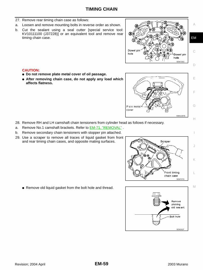
TIMING CHAIN
EM-59
C
D
E
F
G
H
I
J
K
L
M
A
EM
Revision; 2004 April 2003 Murano
27. Remove rear timing chain case as follows:a. Loosen and remove mounting bolts in reverse order as shown.b. Cut the sealant using a seal cutter [special service tool:
KV10111100 (J37228)] or an equivalent tool and remove reartiming chain case.
CAUTION:● Do not remove plate metal cover of oil passage.● After removing chain case, do not apply any load which
affects flatness.
28. Remove RH and LH camshaft chain tensioners from cylinder head as follows if necessary.a. Remove No.1 camshaft brackets. Refer to EM-71, "REMOVAL" .b. Remove secondary chain tensioners with stopper pin attached.29. Use a scraper to remove all traces of liquid gasket from front
and rear timing chain cases, and opposite mating surfaces.
● Remove old liquid gasket from the bolt hole and thread.
SEM735G
KBIA1307E
SEM737G
SEM161F

EM-60
TIMING CHAIN
Revision; 2004 April 2003 Murano
30. Use a scraper to remove all traces of liquid gasket from waterpump cover, chain tensioner cover and intake valve timing con-trol covers.
INSPECTION AFTER REMOVALCheck for cracks and any excessive wear at the roller links of thetiming chain. Replace the timing chain as necessary.
INSTALLATIONNOTE:The below figure shows the relationship between the mating mark on each timing chain and that on the corre-sponding sprocket, with the components installed.
1. Install RH and LH camshaft chain tensioners to cylinder head as follows if removed. Refer to EM-74,"INSTALLATION" .
SEM926E
PBIC0282E
KBIA1053E

TIMING CHAIN
EM-61
C
D
E
F
G
H
I
J
K
L
M
A
EM
Revision; 2004 April 2003 Murano
a. Install secondary chain tensioners with stopper pin attached andnew O-ring.
b. Install No.1 camshaft brackets. Refer to EM-74, "INSTALLA-TION" .
2. Install O-rings onto cylinder block.
3. Install O-rings to cylinder head.
4. Apply liquid gasket to rear timing chain case back side as shown.
● Use Genuine RTV Silicone Sealant or equivalent. Refer to GI-46, "RECOMMENDED CHEMICALPRODUCTS AND SEALANTS" .
PBIC0788E
SEM945G
PBIC1131E

EM-62
TIMING CHAIN
Revision; 2004 April 2003 Murano
5. Align the rear timing chain case and water pump assembly with the dowel pins (RH and LH) on the cylin-der block and install the case.● Make sure the O-rings stay in place during installation to cylinder block and cylinder head.
a. Tighten the mounting bolts in the numerical order as shown.● There are two bolt lengths used. Follow the below for proper
bolt length specifications.
b. After all bolts are temporarily tightened, retighten them to thespecification in the numerical order as shown.● If the RTV Silicone Sealant protrudes, wipe it off immediately.
6. After installing rear timing chain case, check surface height difference between following parts on oil panmounting surface.
● If not within standard, repeat above installation procedure.7. Install chain tension guide.8. Position the crankshaft so No. 1 piston is set at TDC on the
compression stroke.● Make sure that the dowel pin hole, dowel pin and crankshaft
key are located as shown.
CAUTION:Hole on small dia. side must be used for intake side dowel pin hole. Do not misidentify (ignore bigdia. side).
9. Install the timing chains (secondary) and camshaft sprockets.CAUTION:Matching marks between the timing chain and sprocketsslip easily. Confirm all matching mark positions repeatedlyduring the installation process.
a. Push the plunger of the secondary chain tensioner and keep itpressed in with a stopper pin.
Bolt length: Bolt position20 mm (0.79 in) : 1, 2, 3, 6, 7, 8, 9, 1016 mm (0.63 in) : Except the above
: 11.7 - 13.7 N·m (1.2 - 1.4 kg-m, 9 - 10 ft-lb)
StandardRear timing chain case to cylinder block:
–0.24 to 0.14 mm (–0.0094 to 0.0055 in)
Camshaft dowel pin hole (intake side): At cylinder head upper face side in each bank.
Camshaft dowel pin (exhaust side): At cylinder head upper face side in each bank.
Crankshaft key: At cylinder head side of RH bank.
SEM735G
KBIA1073E
SEM430G

TIMING CHAIN
EM-63
C
D
E
F
G
H
I
J
K
L
M
A
EM
Revision; 2004 April 2003 Murano
b. Install secondary timing chains and camshaft sprockets.● Align the mating marks on the secondary timing chain (gold
link) with the ones on the intake and exhaust sprockets(stamped), and install them.NOTE:● Mating marks for the intake sprocket are on the back side
of the secondary camshaft sprocket.● There are two types of mating marks, circle and oval types.
They should be used for the RH and LH banks, respec-tively.
● Align the dowel pin and pin hole on the camshaft with thegroove and dowel pin on the sprocket, and install them.
● On the intake side, align the pin hole on the small diameterside of the camshaft front end with the dowel pin on the backside of the camshaft sprocket, and install them.
● On the exhaust side, align the dowel pin on the camshaft frontend with the pin groove on the camshaft sprocket, and installthem.
● Mounting bolts for the camshaft sprockets must be tightenedin the next step. Tightening them by hand is enough to prevent the dislocation of the dowel pins.
● It may be difficult to visually check the dislocation of matingmarks during and after installation. To make the matchingeasier, make a mating mark on the top of sprocket teeth andits extended line in advance with paint.
10. After confirming the mating marks are aligned, tighten the cam-shaft sprocket mounting bolts.● Secure the camshaft using a wrench at the hexagonal portion
to tighten the mounting bolts.
11. Pull the stopper pins out from the secondary timing chain ten-sioners.
RH bank : use circle type.LH bank : use oval type.
PBIC1117E
PBIC0891E
KBIA1698J
SEM923G

EM-64
TIMING CHAIN
Revision; 2004 April 2003 Murano
12. Install the primary timing chain as follows:a. Install the crankshaft sprocket.
● Make sure the mating marks on the crankshaft sprocket facethe front of the engine.
b. Install the primary timing chain.● Install primary timing chain so the mating mark (punched) on
camshaft sprocket is aligned with the yellow link on the timingchain, while the mating mark (notched) on the crankshaftsprocket is aligned with the orange one on the timing chain,as shown.
● When it is difficult to align mating marks of the primary timingchain with each sprocket, gradually turn the camshaft using awrench on the hexagonal portion to align it with the matingmarks.
● During alignment, be careful to prevent dislocation of matingmark alignments of the secondary timing chains.
SEM929E
PBIC1132E

TIMING CHAIN
EM-65
C
D
E
F
G
H
I
J
K
L
M
A
EM
Revision; 2004 April 2003 Murano
13. Install the internal chain guide and tension guide.14. Install slack guide.
● Do not overtighten the slack guide mounting bolts. It is normalfor a gap to exist under the bolt seats when the mounting boltsare tightened to specification.
15. Install chain tensioner for slack guide.● When installing the chain tensioner, push in the sleeve and
keep it pressed in with the stopper pin.● Remove any dirt and foreign materials completely from the
back and the mounting surfaces of the chain tensioner.● After installation, pull out the stopper pin by pressing the slack
guide.
16. Reconfirm that the mating marks on the sprockets and the timing chain have not slipped out of alignment.
SEM740G
SEM741G
SEM733G

EM-66
TIMING CHAIN
Revision; 2004 April 2003 Murano
17. Install new O-rings on the rear timing chain case.
18. Install the front oil seal on the front timing chain case. Applynew engine oil to the oil seal edges.● Install it so that each seal lip is oriented as shown in figure.
● Using a suitable drift, press-fit oil seal until it becomes flushwith timing chain case end face.
● Make sure the garter spring is in position and seal lip is notinverted.
19. Install the water pump cover and the chain tensioner cover tofront cover.● Apply RTV Silicone Sealant or equivalent. Refer to GI-46,
"RECOMMENDED CHEMICAL PRODUCTS AND SEAL-ANTS" .
SEM946G
SEM715A
PBIC0790E
SEM744GA

TIMING CHAIN
EM-67
C
D
E
F
G
H
I
J
K
L
M
A
EM
Revision; 2004 April 2003 Murano
20. Install front timing chain case as follows:a. Apply liquid gasket to front timing chain case back side as
shown.b. Install dowel pin on the rear timing chain case into dowel pin
hole on front timing chain case.
c. Tighten bolts to the specified torque in order shown in the figure.
d. After tightening, retighten them to specified torque in numericalorder shown in figure.
21. After installing the front timing chain case, check the surfaceheight difference between the following parts on the oil panmounting surface.● If not within specification, repeat the installation procedure.
22. Install RH and LH intake valve timing control covers as follows:a. Install seal rings in shaft grooves.b. Apply liquid gasket to the intake valve timing control covers.
● Use Genuine RTV Silicone Sealant or equivalent. Refer to GI-46, "RECOMMENDED CHEMICAL PRODUCTS AND SEAL-ANTS" .
PBIC1133E
8 mm (0.31 in) dia. bolts : 1, 2
: 25.5 - 31.3 N·m (2.6 - 3.2 kg-m, 19 - 23 ft-lb)6 mm (0.24 in) dia. bolts : Except the above
: 11.7 - 13.7 N·m (1.2 - 1.4 kg-m, 9 - 10 ft-lb)
SEM730G
StandardFront timing chain case to rear timing chain case:
–0.14 to 0.14 mm (–0.005 to 0.0055 in)
SEM943G
SEM747G
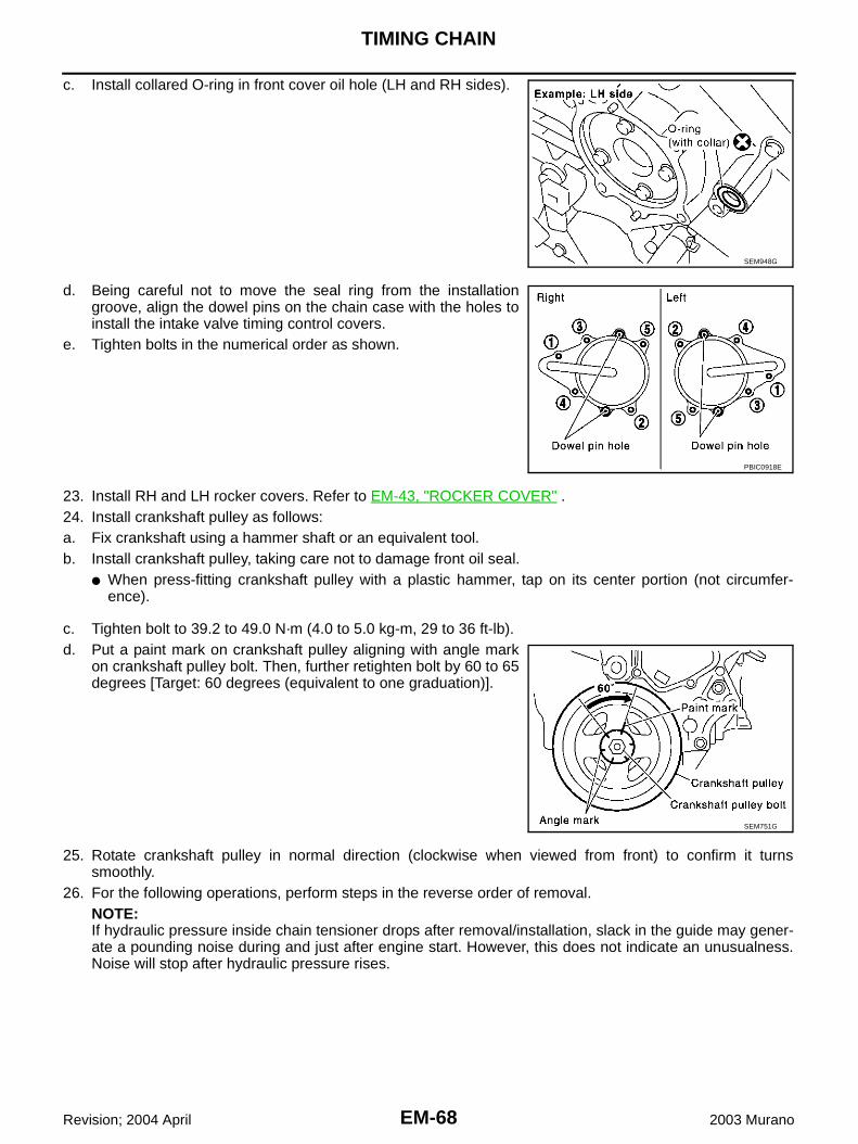
EM-68
TIMING CHAIN
Revision; 2004 April 2003 Murano
c. Install collared O-ring in front cover oil hole (LH and RH sides).
d. Being careful not to move the seal ring from the installationgroove, align the dowel pins on the chain case with the holes toinstall the intake valve timing control covers.
e. Tighten bolts in the numerical order as shown.
23. Install RH and LH rocker covers. Refer to EM-43, "ROCKER COVER" .24. Install crankshaft pulley as follows:a. Fix crankshaft using a hammer shaft or an equivalent tool.b. Install crankshaft pulley, taking care not to damage front oil seal.
● When press-fitting crankshaft pulley with a plastic hammer, tap on its center portion (not circumfer-ence).
c. Tighten bolt to 39.2 to 49.0 N·m (4.0 to 5.0 kg-m, 29 to 36 ft-lb).d. Put a paint mark on crankshaft pulley aligning with angle mark
on crankshaft pulley bolt. Then, further retighten bolt by 60 to 65degrees [Target: 60 degrees (equivalent to one graduation)].
25. Rotate crankshaft pulley in normal direction (clockwise when viewed from front) to confirm it turnssmoothly.
26. For the following operations, perform steps in the reverse order of removal.NOTE:If hydraulic pressure inside chain tensioner drops after removal/installation, slack in the guide may gener-ate a pounding noise during and just after engine start. However, this does not indicate an unusualness.Noise will stop after hydraulic pressure rises.
SEM948G
PBIC0918E
SEM751G
TIMING CHAIN
EM-69
C
D
E
F
G
H
I
J
K
L
M
A
EM
Revision; 2004 April 2003 Murano
INSPECTION AFTER INSTALLATION● Before starting engine, check the levels of engine coolant, lubrications and working oils. If less than
required quantity, fill to the specified level.● Use procedure below to check for fuel leakage.– Turn ignition switch ON (with engine stopped). With fuel pressure applied to fuel piping, check for fuel
leakage at connection points.– Start engine. With engine speed increased, check again for fuel leakage at connection points.● Run engine to check for unusual noise and vibration.● Warm up engine thoroughly to make sure there is no leakage of engine coolant, lubricants, working oil,
fuel and exhaust gas.● Bleed air from passages in pipes and tubes of applicable lines, such as in cooling system.● After cooling down engine, again check amounts of engine coolant, lubricants, oil, and fluid. Refill to spec-
ified level, if necessary.

EM-70
CAMSHAFT
Revision; 2004 April 2003 Murano
CAMSHAFT PFP:13001
Removal and Installation ABS0032R
1.Intake valve timing control solenoid valve
2. Gasket 3. Camshaft bracket (No.2 to No.4)
4. Camshaft (EXH) 5. Camshaft (INT) 6. Camshaft bracket (No.1)
7. Dowel pin 8. Valve lifter 9. O-ring
10. Chain tensioner (Secondary) 11. Spring 12. Plunger
13. Cylinder head (RH bank) 14. Cylinder head (LH bank) 15.Camshaft position sensor (PHASE) (RH bank)
16.Camshaft position sensor (PHASE) (LH bank)
PBIC1769E

CAMSHAFT
EM-71
C
D
E
F
G
H
I
J
K
L
M
A
EM
Revision; 2004 April 2003 Murano
REMOVAL1. Remove front timing chain case, camshaft sprocket, timing chain and rear timing chain case. Refer to EM-
54, "TIMING CHAIN" .2. If necessary, remove camshaft position sensor (PHASE) (RH
and LH banks) from cylinder head back side.CAUTION:● Handle carefully to avoid dropping and shocks.● Do not disassemble.● Do not allow metal powder to adhere to magnetic part at
sensor tip.● Do not place sensors in a location where they are
exposed to magnetism.
3. Remove the intake valve timing control solenoid valves.● Discard the intake valve timing control solenoid valve gaskets
and use new gaskets for installation.
4. Remove the intake and exhaust camshaft brackets.● Mark the camshafts, camshaft brackets, and bolts so they are
placed in the same position and direction for installation.● Equally loosen the camshaft bracket bolts in several steps in
the numerical order shown.
5. Remove camshaft.6. Remove valve lifter.
● Identify installation positions, and store them without mixing them up.
KBIA1046E
SEM443GA
SEM856E
SEM857E

EM-72
CAMSHAFT
Revision; 2004 April 2003 Murano
7. Remove secondary timing chain tensioner from cylinder head.● Remove secondary chain tensioner with its stopper pin
attached.NOTE:Stopper pin was attached when secondary timing chain wasremoved.
INSPECTION AFTER REMOVALCamshaft Runout1. Put V block on precise flat bed, and support No. 2 and No. 4
journal of camshaft.2. Set dial gauge vertically to No. 3 journal.3. Turn camshaft to one direction with hands, and measure cam-
shaft runout on dial gauge. (Total indicator reading)
4. If it exceeds the limit, replace camshaft.
Camshaft Cam Height1. Measure camshaft cam height.
2. If wear is beyond the limit, replace camshaft.
Camshaft Journal ClearanceOuter Diameter of Camshaft Journal● Measure outer diameter of camshaft journal.
SEM947G
Limit : 0.05 mm (0.0020 in)
PBIC0929E
Standard cam height (intake and exhaust): 44.865 - 45.055 mm (1.7663 - 1.7738 in)
Cam wear limit: 0.2 mm (0.008 in)
EMQ0072D
Standard outer diameter: No. 1 : 25.935 - 25.955 mm (1.0211 - 1.0218 in) No. 2, 3, 4 : 23.445 - 23.465 mm (0.9230 - 0.9238 in)
PBIC0040E
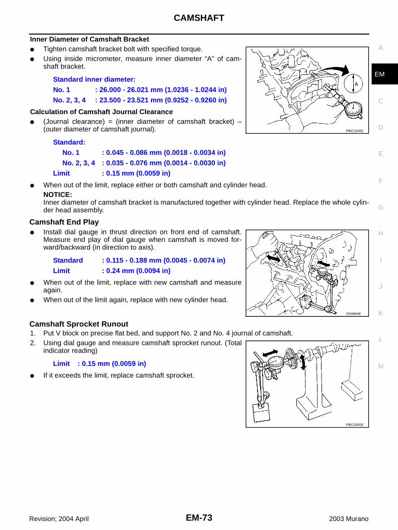
CAMSHAFT
EM-73
C
D
E
F
G
H
I
J
K
L
M
A
EM
Revision; 2004 April 2003 Murano
Inner Diameter of Camshaft Bracket● Tighten camshaft bracket bolt with specified torque.● Using inside micrometer, measure inner diameter “A” of cam-
shaft bracket.
Calculation of Camshaft Journal Clearance● (Journal clearance) = (inner diameter of camshaft bracket) –
(outer diameter of camshaft journal).
● When out of the limit, replace either or both camshaft and cylinder head.NOTICE:Inner diameter of camshaft bracket is manufactured together with cylinder head. Replace the whole cylin-der head assembly.
Camshaft End Play● Install dial gauge in thrust direction on front end of camshaft.
Measure end play of dial gauge when camshaft is moved for-ward/backward (in direction to axis).
● When out of the limit, replace with new camshaft and measureagain.
● When out of the limit again, replace with new cylinder head.
Camshaft Sprocket Runout1. Put V block on precise flat bed, and support No. 2 and No. 4 journal of camshaft.2. Using dial gauge and measure camshaft sprocket runout. (Total
indicator reading)
● If it exceeds the limit, replace camshaft sprocket.
Standard inner diameter:No. 1 : 26.000 - 26.021 mm (1.0236 - 1.0244 in)No. 2, 3, 4 : 23.500 - 23.521 mm (0.9252 - 0.9260 in)
Standard:No. 1 : 0.045 - 0.086 mm (0.0018 - 0.0034 in)No. 2, 3, 4 : 0.035 - 0.076 mm (0.0014 - 0.0030 in)
Limit : 0.15 mm (0.0059 in)
PBIC1645E
Standard : 0.115 - 0.188 mm (0.0045 - 0.0074 in)Limit : 0.24 mm (0.0094 in)
SEM864E
Limit : 0.15 mm (0.0059 in)
PBIC0930E

EM-74
CAMSHAFT
Revision; 2004 April 2003 Murano
Valve Lifter Check if surface of valve lifter has any wear or cracks.● If anything above is found, replace valve lifter.
Valve Lifter ClearanceOuter Diameter of Valve Lifter● Measure outer diameter of valve lifter.
Valve Lifter Hole Diameter● Using inside micrometer, measure diameter of valve lifter hole of
cylinder head.
Calculation of Valve Lifter Clearance● (Valve lifter clearance) = (hole diameter of valve lifter) – (outer
diameter of valve lifter).
● When out of specified range, referring to each specification of outer and inner diameter, replace either orboth valve lifter and cylinder head.
INSTALLATION1. Install secondary chain tensioners on both sides of cylinder
head.● Install chain tensioner with its stopper pin attached. ● Install tensioner with sliding part facing downward on right-
side cylinder head, and with sliding part facing upward on left-side cylinder head.
● Install O-ring as shown.
2. Install valve lifter.● Install it in the original position.
KBIA0182E
Valve lifter outer diameter (Intake and exhaust): 33.977 - 33.987mm (1.3377 - 1.3381 in)
JEM798G
Standard (Intake and exhaust): 34.000 - 34.016 mm (1.3386 - 1.3392 in)
Standard (Intake and exhaust): 0.013 - 0.039 mm (0.0005 - 0.0015 in) SEM867E
SEM947G
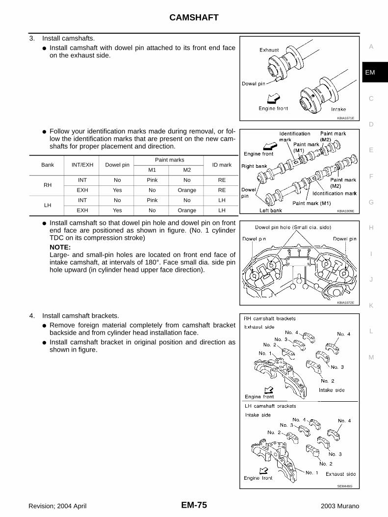
CAMSHAFT
EM-75
C
D
E
F
G
H
I
J
K
L
M
A
EM
Revision; 2004 April 2003 Murano
3. Install camshafts.● Install camshaft with dowel pin attached to its front end face
on the exhaust side.
● Follow your identification marks made during removal, or fol-low the identification marks that are present on the new cam-shafts for proper placement and direction.
● Install camshaft so that dowel pin hole and dowel pin on frontend face are positioned as shown in figure. (No. 1 cylinderTDC on its compression stroke)NOTE:Large- and small-pin holes are located on front end face ofintake camshaft, at intervals of 180°. Face small dia. side pinhole upward (in cylinder head upper face direction).
4. Install camshaft brackets.● Remove foreign material completely from camshaft bracket
backside and from cylinder head installation face.● Install camshaft bracket in original position and direction as
shown in figure.
KBIA1071E
Bank INT/EXH Dowel pinPaint marks
ID markM1 M2
RHINT No Pink No RE
EXH Yes No Orange RE
LHINT No Pink No LH
EXH Yes No Orange LH KBIA1009E
KBIA1072E
SEM446G

EM-76
CAMSHAFT
Revision; 2004 April 2003 Murano
● Install No.2 to 4 camshaft brackets aligning the stamp marksas shown.NOTE:There are no identification marks indicating left and right forNo. 1 camshaft bracket.
● Apply sealant to mating surface of No.1 camshaft bracket asshown on RH and LH banks.
● Use Genuine RTV Silicone Sealant or equivalent. Refer to GI-46, "RECOMMENDED CHEMICAL PRODUCTS AND SEAL-ANTS" .
5. Tighten the camshaft brackets in the following steps, in numeri-cal order as shown.
a. Tighten No. 7 to 10, then tighten No.1 to 6 in order as shown.
b. Tighten all bolts in the numerical order as shown.
c. Tighten all bolts in the numerical order as shown.
SEM564G
PBIC0915E
: 1.96 N·m (0.2 kg-m, 17 in-lb)
: 5.88 N·m (0.6 kg-m, 52 in-lb)
: 9.02 - 11.8 N·m (0.92 - 1.20 kg-m, 80 - 104 in-lb)
PBIC0794E

CAMSHAFT
EM-77
C
D
E
F
G
H
I
J
K
L
M
A
EM
Revision; 2004 April 2003 Murano
6. Measure difference in levels between front end faces of No. 1camshaft bracket and cylinder head.
● If measurement is outside the specified range, re-install cam-shaft and camshaft bracket.
7. Inspect and adjust valve clearance. Refer to EM-77, "Valve Clearance" .8. Install in the reverse order of removal after this step.
Valve Clearance ABS003MI
INSPECTION● Perform inspection as follows after removal, installation or
replacement of camshaft or valve-related parts, or if there isunusual engine conditions regarding valve clearance.
1. Remove RH and LH rocker covers with power tool.Refer to EM-43, "ROCKER COVER" .
2. Measure valve clearance as below:a. Set No.1 cylinder at TDC of its compression stroke.
● Align crankshaft pulley timing mark (grooved line withoutcolor) with timing indicator.
● Check that No. 1 cylinder intake and exhaust cam nose is fac-ing in direction shown in figure.
● If not, rotate crankshaft pulley 360° clockwise (when viewedfrom front).
Standard : –0.14 to 0.14 mm (–0.0055 to 0.0055 in)
EMQ0044D
SEM713A
SEM918G
SEM418G

EM-78
CAMSHAFT
Revision; 2004 April 2003 Murano
b. Using a feeler gauge, measure valve clearance.
*: Approximately 80°C (176°F) (Reference data)
● No.1 cylinder at compression TDC
CAUTION:If inspection was carried out with cold engine, check thatvalues with fully warmed up engine are still within specifi-cations.
c. Rotate crankshaft by 240° clockwise (when viewed from front) toalign No. 3 cylinder at TDC of its compression stroke.NOTE:Crankshaft pulley mounting bolt flange has a stamped line every60°. They can be used as a guide to rotation angle.
Valve clearance standard:Cold Intake : 0.26 - 0.34 mm (0.010 - 0.013 in)
Exhaust : 0.29 - 0.37 mm (0.011 - 0.015 in)Hot* Intake : 0.304 - 0.416 mm (0.012 - 0.016 in)
Exhaust : 0.308 - 0.432 mm (0.012 - 0.016 in)
SEM139D
KBIA0185E
Measuring position (RH bank) No.1 CYL. No.3 CYL. No.5 CYL.
No.1 cylinder at TDC
EXH ×
INT ×
Measuring position (LH bank) No.2 CYL. No.4 CYL. No.6 CYL.
No.1 cylinder at TDC
INT ×
EXH ×
SEM893E
SEM751G

CAMSHAFT
EM-79
C
D
E
F
G
H
I
J
K
L
M
A
EM
Revision; 2004 April 2003 Murano
● No.3 cylinder at compression TDC
d. Turn crankshaft pulley clockwise by 240° from the position ofNo. 5 cylinder at compression TDC.
3. For measurements that are outside the specified range, performadjustment below.
ADJUSTMENT● Perform adjustment depending on selected head thickness of valve lifter.● The specified valve lifter thickness is the dimension at normal temperatures. Ignore dimensional differ-
ences caused by temperature. Use the specifications for hot engine condition to adjust.1. Remove camshaft. Refer to EM-70, "Removal and Installation" .2. Remove the valve lifters at the locations that are outside the standard.
Measuring position (RH bank) No.1 CYL. No.3 CYL. No.5 CYL.
No.3 cylinder at TDC
EXH ×
INT ×
Measuring position (LH bank) No.2 CYL. No.4 CYL. No.6 CYL.
No.3 cylinder at TDC
INT ×
EXH ×
SEM894E
Measuring position (RH bank) No.1 CYL. No.3 CYL. No.5 CYL.
No.5 cylinder at TDC
EXH ×
INT ×
Measuring position (LH bank) No.2 CYL. No.4 CYL. No.6 CYL.
No.5 cylinder at TDC
INT ×
EXH ×
SEM958E
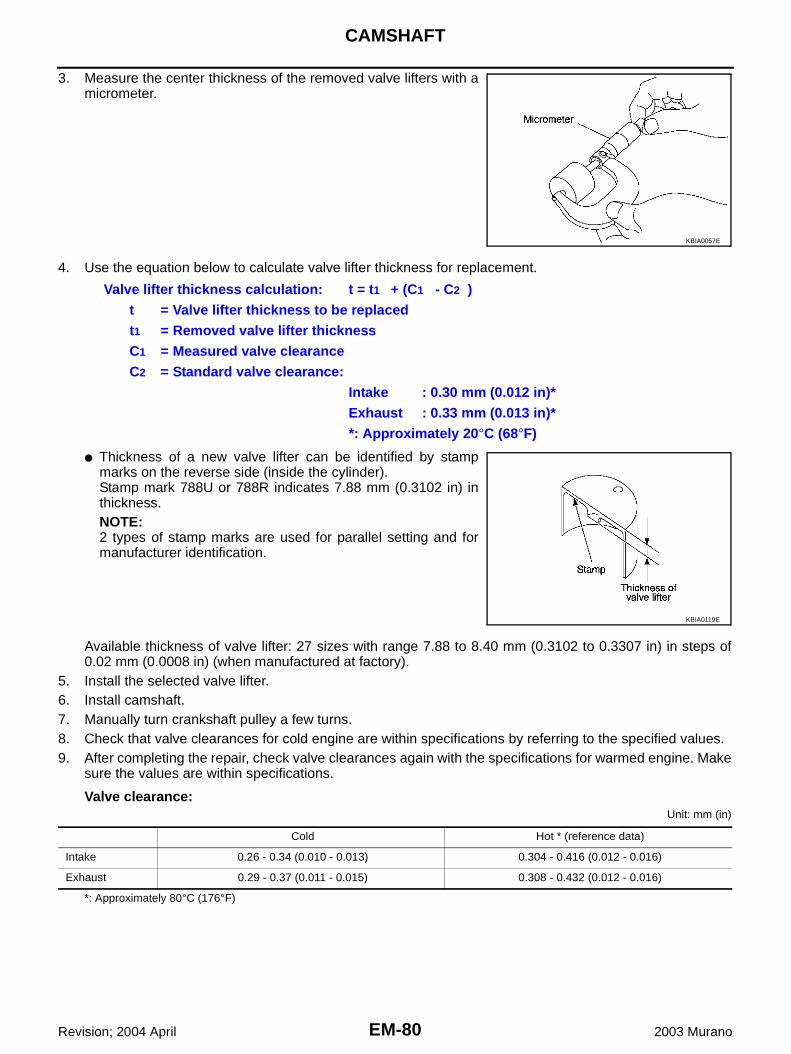
EM-80
CAMSHAFT
Revision; 2004 April 2003 Murano
3. Measure the center thickness of the removed valve lifters with amicrometer.
4. Use the equation below to calculate valve lifter thickness for replacement.
● Thickness of a new valve lifter can be identified by stampmarks on the reverse side (inside the cylinder).Stamp mark 788U or 788R indicates 7.88 mm (0.3102 in) inthickness.NOTE:2 types of stamp marks are used for parallel setting and formanufacturer identification.
Available thickness of valve lifter: 27 sizes with range 7.88 to 8.40 mm (0.3102 to 0.3307 in) in steps of0.02 mm (0.0008 in) (when manufactured at factory).
5. Install the selected valve lifter.6. Install camshaft.7. Manually turn crankshaft pulley a few turns. 8. Check that valve clearances for cold engine are within specifications by referring to the specified values.9. After completing the repair, check valve clearances again with the specifications for warmed engine. Make
sure the values are within specifications.
Valve clearance:Unit: mm (in)
*: Approximately 80°C (176°F)
KBIA0057E
Valve lifter thickness calculation: t = t1 + (C1 - C2 )t = Valve lifter thickness to be replacedt1 = Removed valve lifter thicknessC1 = Measured valve clearanceC2 = Standard valve clearance:
Intake : 0.30 mm (0.012 in)*Exhaust : 0.33 mm (0.013 in)**: Approximately 20°C (68°F)
KBIA0119E
Cold Hot * (reference data)
Intake 0.26 - 0.34 (0.010 - 0.013) 0.304 - 0.416 (0.012 - 0.016)
Exhaust 0.29 - 0.37 (0.011 - 0.015) 0.308 - 0.432 (0.012 - 0.016)
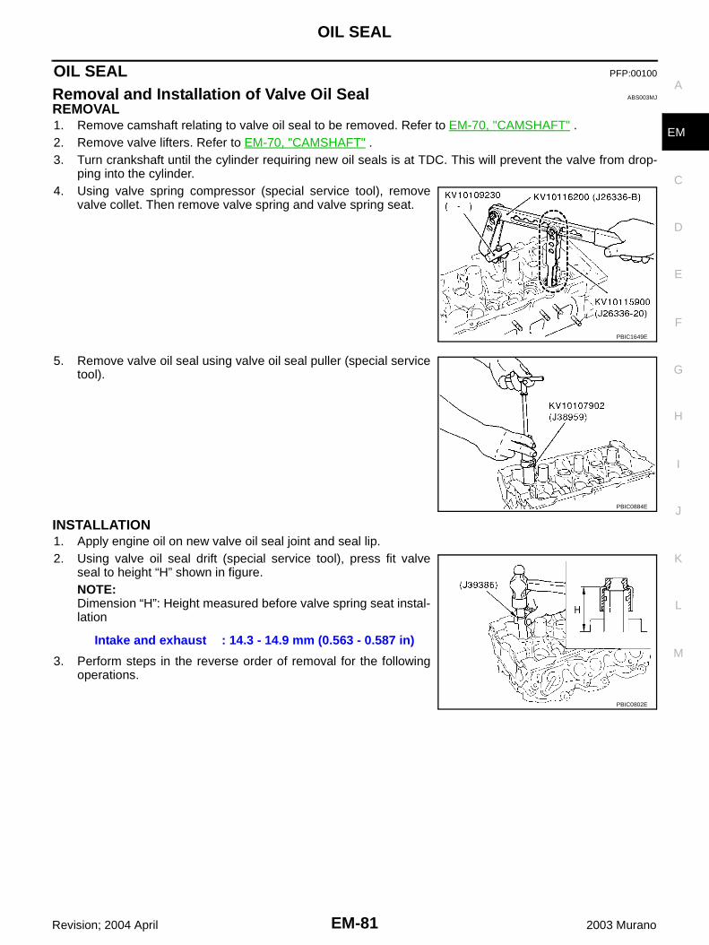
OIL SEAL
EM-81
C
D
E
F
G
H
I
J
K
L
M
A
EM
Revision; 2004 April 2003 Murano
OIL SEAL PFP:00100
Removal and Installation of Valve Oil Seal ABS003MJ
REMOVAL1. Remove camshaft relating to valve oil seal to be removed. Refer to EM-70, "CAMSHAFT" .2. Remove valve lifters. Refer to EM-70, "CAMSHAFT" .3. Turn crankshaft until the cylinder requiring new oil seals is at TDC. This will prevent the valve from drop-
ping into the cylinder.4. Using valve spring compressor (special service tool), remove
valve collet. Then remove valve spring and valve spring seat.
5. Remove valve oil seal using valve oil seal puller (special servicetool).
INSTALLATION1. Apply engine oil on new valve oil seal joint and seal lip.2. Using valve oil seal drift (special service tool), press fit valve
seal to height “H” shown in figure.NOTE:Dimension “H”: Height measured before valve spring seat instal-lation
3. Perform steps in the reverse order of removal for the followingoperations.
PBIC1649E
PBIC0884E
Intake and exhaust : 14.3 - 14.9 mm (0.563 - 0.587 in)
PBIC0802E
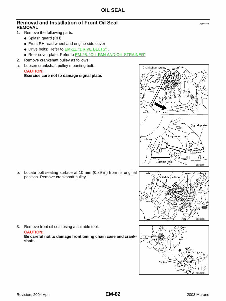
EM-82
OIL SEAL
Revision; 2004 April 2003 Murano
Removal and Installation of Front Oil Seal ABS003MK
REMOVAL1. Remove the following parts:
● Splash guard (RH)● Front RH road wheel and engine side cover● Drive belts; Refer to EM-11, "DRIVE BELTS" .● Rear cover plate; Refer to EM-26, "OIL PAN AND OIL STRAINER"
2. Remove crankshaft pulley as follows:a. Loosen crankshaft pulley mounting bolt.
CAUTION:Exercise care not to damage signal plate.
b. Locate bolt seating surface at 10 mm (0.39 in) from its originalposition. Remove crankshaft pulley.
3. Remove front oil seal using a suitable tool.CAUTION:Be careful not to damage front timing chain case and crank-shaft.
SEM965F
SEM915E
SEM829E
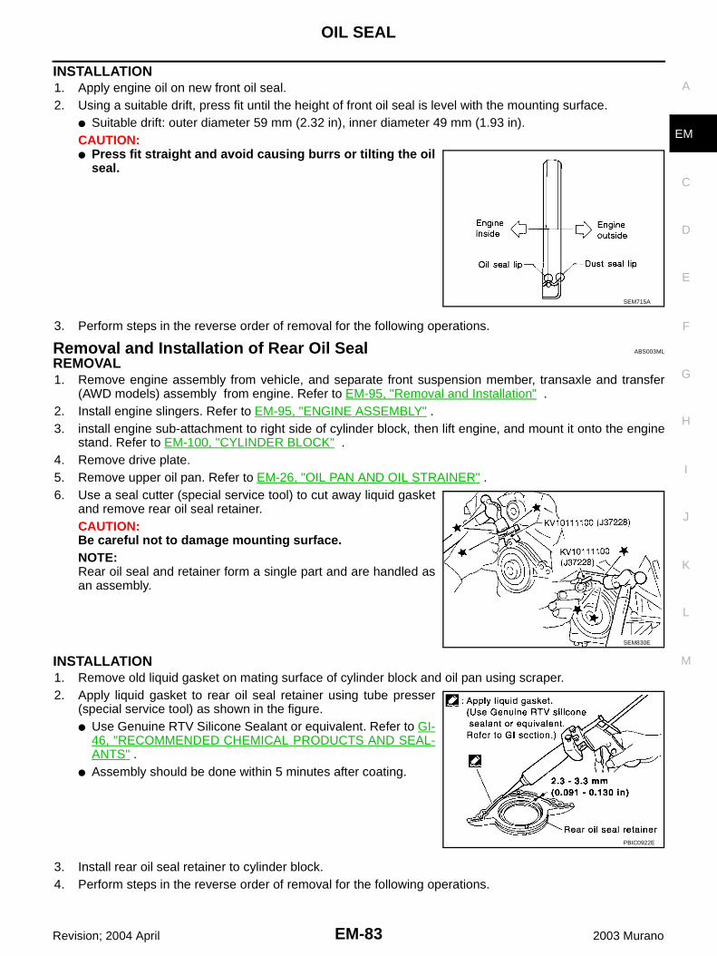
OIL SEAL
EM-83
C
D
E
F
G
H
I
J
K
L
M
A
EM
Revision; 2004 April 2003 Murano
INSTALLATION1. Apply engine oil on new front oil seal.2. Using a suitable drift, press fit until the height of front oil seal is level with the mounting surface.
● Suitable drift: outer diameter 59 mm (2.32 in), inner diameter 49 mm (1.93 in).CAUTION:● Press fit straight and avoid causing burrs or tilting the oil
seal.
3. Perform steps in the reverse order of removal for the following operations.
Removal and Installation of Rear Oil Seal ABS003ML
REMOVAL1. Remove engine assembly from vehicle, and separate front suspension member, transaxle and transfer
(AWD models) assembly from engine. Refer to EM-95, "Removal and Installation" .2. Install engine slingers. Refer to EM-95, "ENGINE ASSEMBLY" .3. install engine sub-attachment to right side of cylinder block, then lift engine, and mount it onto the engine
stand. Refer to EM-100, "CYLINDER BLOCK" .4. Remove drive plate.5. Remove upper oil pan. Refer to EM-26, "OIL PAN AND OIL STRAINER" .6. Use a seal cutter (special service tool) to cut away liquid gasket
and remove rear oil seal retainer.CAUTION:Be careful not to damage mounting surface.NOTE:Rear oil seal and retainer form a single part and are handled asan assembly.
INSTALLATION1. Remove old liquid gasket on mating surface of cylinder block and oil pan using scraper.2. Apply liquid gasket to rear oil seal retainer using tube presser
(special service tool) as shown in the figure.● Use Genuine RTV Silicone Sealant or equivalent. Refer to GI-
46, "RECOMMENDED CHEMICAL PRODUCTS AND SEAL-ANTS" .
● Assembly should be done within 5 minutes after coating.
3. Install rear oil seal retainer to cylinder block.4. Perform steps in the reverse order of removal for the following operations.
SEM715A
SEM830E
PBIC0922E
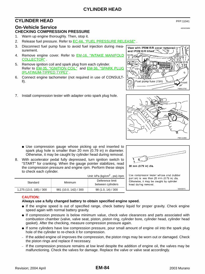
EM-84
CYLINDER HEAD
Revision; 2004 April 2003 Murano
CYLINDER HEAD PFP:11041
On-Vehicle Service ABS003MM
CHECKING COMPRESSION PRESSURE1. Warm up engine thoroughly. Then, stop it.2. Release fuel pressure. Refer to EC-66, "FUEL PRESSURE RELEASE" .3. Disconnect fuel pump fuse to avoid fuel injection during mea-
surement.4. Remove engine cover. Refer to EM-16, "INTAKE MANIFOLD
COLLECTOR" .5. Remove ignition coil and spark plug from each cylinder.
Refer to EM-35, "IGNITION COIL" and EM-36, "SPARK PLUG(PLATINUM-TIPPED TYPE)" .
6. Connect engine tachometer (not required in use of CONSULT-ll).
7. Install compression tester with adapter onto spark plug hole.
● Use compression gauge whose picking up end inserted tospark plug hole is smaller than 20 mm (0.79 in) in diameter.Otherwise, it may be caught by cylinder head during removal.
8. With accelerator pedal fully depressed, turn ignition switch to“START” for cranking. When the gauge pointer stabilizes, readthe compression pressure and engine rpm. Perform these stepsto check each cylinder.
Unit: kPa (kg/cm2 , psi) /rpm
CAUTION:Always use a fully changed battery to obtain specified engine speed.● If the engine speed is out of specified range, check battery liquid for proper gravity. Check engine
speed again with normal battery gravity. ● If compression pressure is below minimum value, check valve clearances and parts associated with
combustion chamber (valve, valve seat, piston, piston ring, cylinder bore, cylinder head, cylinder headgasket). After the checking, measure compression pressure again.
● If some cylinders have low compression pressure, pour small amount of engine oil into the spark plughole of the cylinder to re-check it for compression.
– If the added engine oil improves the compression, the piston rings may be worn out or damaged. Checkthe piston rings and replace if necessary.
– If the compression pressure remains at low level despite the addition of engine oil, the valves may bemalfunctioning. Check the valves for damage. Replace the valve or valve seat accordingly.
PBIB1375E
PBIC1186E
Standard MinimumDeference limit
between cylinders
1,275 (13.0, 185) / 300 981 (10.0, 142) / 300 98 (1.0, 14) / 300 SEM387C

CYLINDER HEAD
EM-85
C
D
E
F
G
H
I
J
K
L
M
A
EM
Revision; 2004 April 2003 Murano
● If two adjacent cylinders have respectively low compression pressure and their compression remainslow even after the addition of engine oil, the gaskets are leaking. In such a case, replace the cylinderhead gaskets.
9. After inspection is completed, install removed parts.
Removal and Installation ABS003MN
REMOVAL1. Remove the following components and related parts:
● Fuel tube and fuel injector assembly. Refer to EM-38, "FUEL INJECTOR AND FUEL TUBE" .● Intake manifold. Refer to EM-20, "INTAKE MANIFOLD" .● Exhaust manifold. Refer to EM-22, "EXHAUST MANIFOLD AND THREE WAY CATALYST" .● Water inlet and thermostat assembly. Refer to CO-24, "THERMOSTAT AND THERMOSTAT HOUS-
ING" .● Water outlet and water piping. Refer to CO-26, "WATER OUTLET AND WATER PIPING" .
2. Remove camshaft. Refer to EM-70, "CAMSHAFT" .3. Remove cylinder head loosening bolts in reverse order shown in
the figure.
1. Cylinder head (LH bank) 2. Cylinder head bolt 3. Cylinder head (RH bank)
4. Cylinder head gasket 5. Oil level gauge
PBIC1187E
PBIC0798E

EM-86
CYLINDER HEAD
Revision; 2004 April 2003 Murano
INSPECTION AFTER REMOVALOuter Diameter of Cylinder Head Bolts● Cylinder head bolts are tightened by plastic zone tightening
method. Whenever the size difference between d1 and d2exceeds the limit, replace them with new one.
● If reduction of outer diameter appears in a position other thand2, use it as d2 point.
INSTALLATION1. Install cylinder head gasket.2. Turn the crankshaft until No. 1 piston is set at TDC on the com-
pression stroke.● The crankshaft key should line up with the right bank cylinder
center line as shown.
3. Install cylinder head follow the steps below to tighten cylinderhead bolts in the order shown in figure.
a. Tighten all bolts to 98.1 N·m (10 kg-m, 72 ft-lb).b. Completely loosen to 0 N·m (0 kg-m, 0 ft-lb).
CAUTION:In step “b”, loosen bolts in the reverse order of that indi-cated in figure.
c. Tighten all bolts to 34.3 to 44.1 N·m (3.5 to 4.4 kg-m, 26 to 32 ft-lb).
d. Turn all bolts 90 to 95 degrees clockwise [target: 90 degrees(angle tightening)].
PBIC0799E
Limit (d1 - d2) : 0.11 mm (0.0043 in)
SEM957E
SEM532G
PBIC0798E
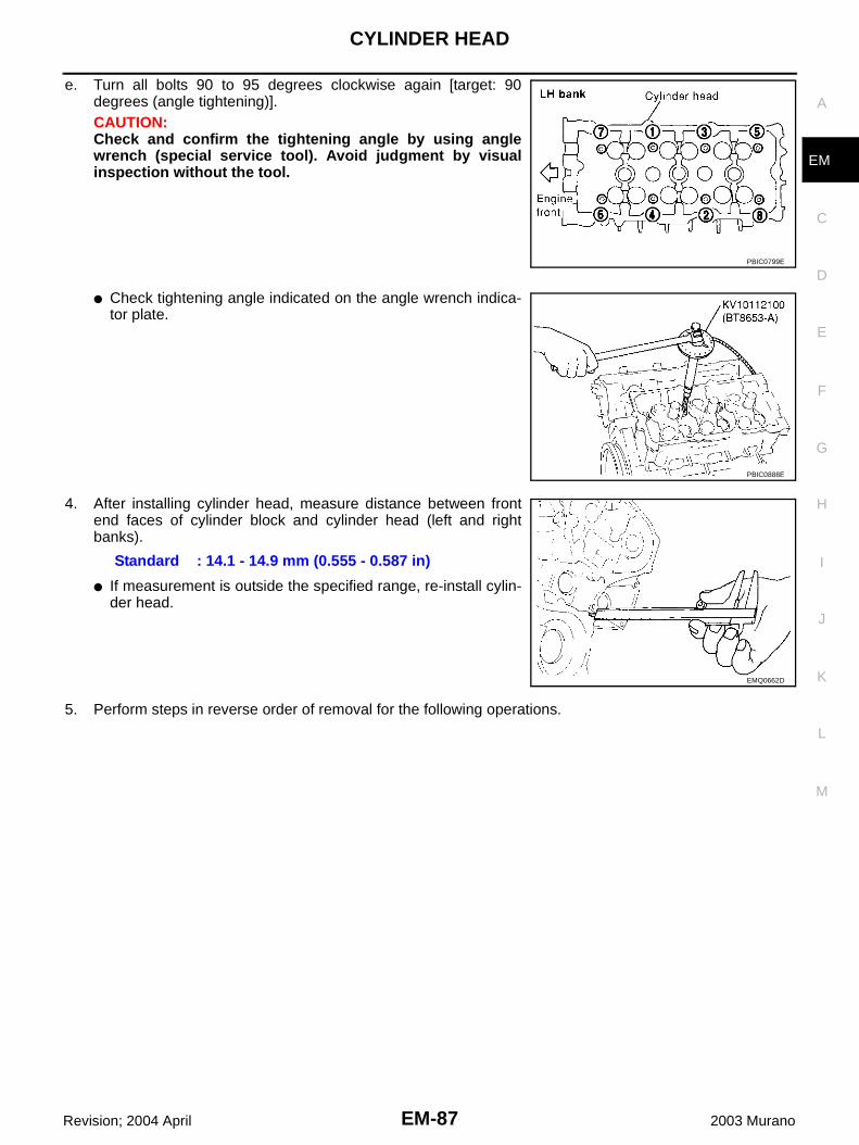
CYLINDER HEAD
EM-87
C
D
E
F
G
H
I
J
K
L
M
A
EM
Revision; 2004 April 2003 Murano
e. Turn all bolts 90 to 95 degrees clockwise again [target: 90degrees (angle tightening)].CAUTION:Check and confirm the tightening angle by using anglewrench (special service tool). Avoid judgment by visualinspection without the tool.
● Check tightening angle indicated on the angle wrench indica-tor plate.
4. After installing cylinder head, measure distance between frontend faces of cylinder block and cylinder head (left and rightbanks).
● If measurement is outside the specified range, re-install cylin-der head.
5. Perform steps in reverse order of removal for the following operations.
PBIC0799E
PBIC0888E
Standard : 14.1 - 14.9 mm (0.555 - 0.587 in)
EMQ0662D
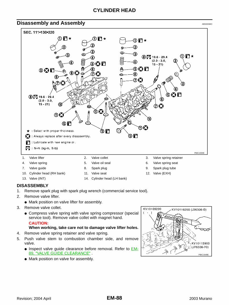
EM-88
CYLINDER HEAD
Revision; 2004 April 2003 Murano
Disassembly and Assembly ABS003MO
DISASSEMBLY1. Remove spark plug with spark plug wrench (commercial service tool).2. Remove valve lifter.
● Mark position on valve lifter for assembly.3. Remove valve collet.
● Compress valve spring with valve spring compressor (specialservice tool). Remove valve collet with magnet hand.CAUTION:When working, take care not to damage valve lifter holes.
4. Remove valve spring retainer and valve spring.5. Push valve stem to combustion chamber side, and remove
valve.● Inspect valve guide clearance before removal. Refer to EM-
89, "VALVE GUIDE CLEARANCE" .● Mark position on valve for assembly.
1. Valve lifter 2. Valve collet 3. Valve spring retainer
4. Valve spring 5. Valve oil seal 6. Valve spring seat
7. Valve guide 8. Spark plug 9. Spark plug tube
10. Cylinder head (RH bank) 11. Valve seat 12. Valve (EXH)
13. Valve (INT) 14. Cylinder head (LH bank)
PBIC1594E
PBIC1649E
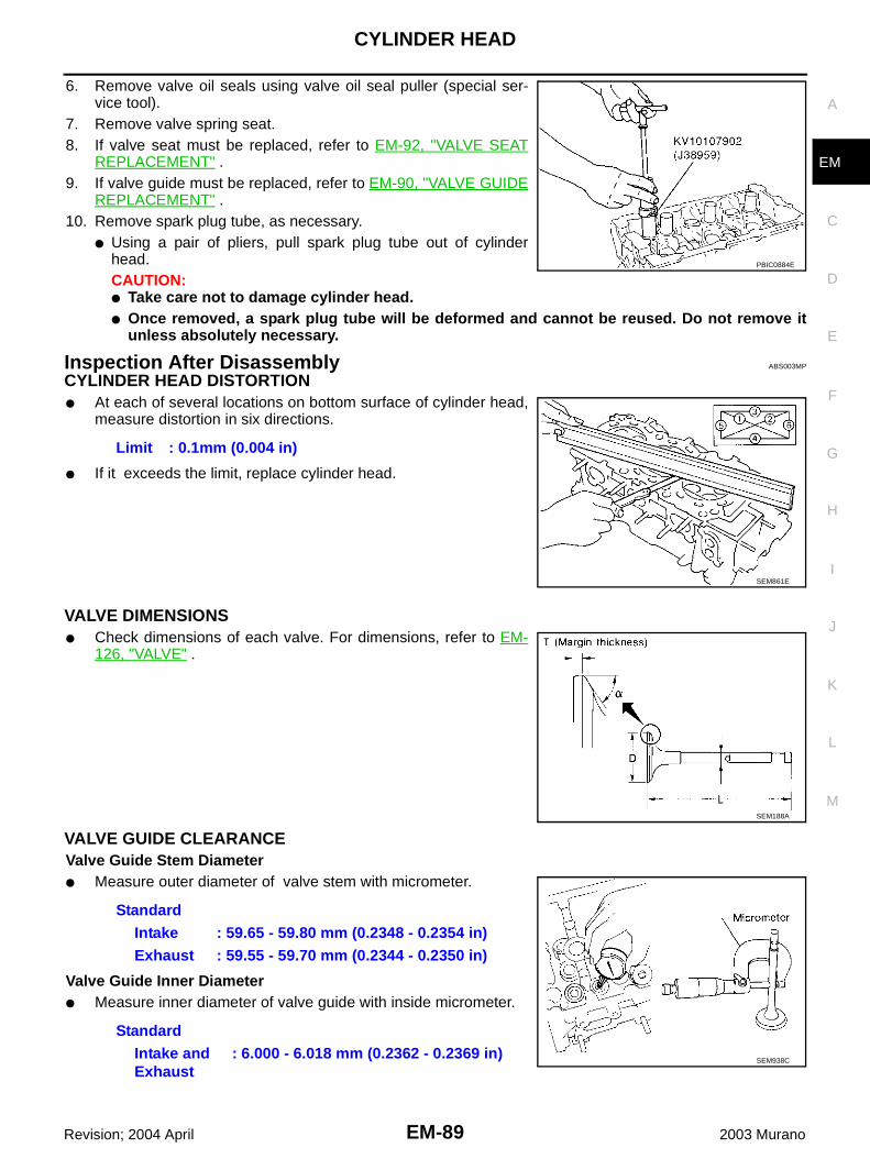
CYLINDER HEAD
EM-89
C
D
E
F
G
H
I
J
K
L
M
A
EM
Revision; 2004 April 2003 Murano
6. Remove valve oil seals using valve oil seal puller (special ser-vice tool).
7. Remove valve spring seat.8. If valve seat must be replaced, refer to EM-92, "VALVE SEAT
REPLACEMENT" .9. If valve guide must be replaced, refer to EM-90, "VALVE GUIDE
REPLACEMENT" .10. Remove spark plug tube, as necessary.
● Using a pair of pliers, pull spark plug tube out of cylinderhead. CAUTION:● Take care not to damage cylinder head.● Once removed, a spark plug tube will be deformed and cannot be reused. Do not remove it
unless absolutely necessary.
Inspection After Disassembly ABS003MP
CYLINDER HEAD DISTORTION● At each of several locations on bottom surface of cylinder head,
measure distortion in six directions.
● If it exceeds the limit, replace cylinder head.
VALVE DIMENSIONS● Check dimensions of each valve. For dimensions, refer to EM-
126, "VALVE" .
VALVE GUIDE CLEARANCEValve Guide Stem Diameter● Measure outer diameter of valve stem with micrometer.
Valve Guide Inner Diameter● Measure inner diameter of valve guide with inside micrometer.
PBIC0884E
Limit : 0.1mm (0.004 in)
SEM861E
SEM188A
StandardIntake : 59.65 - 59.80 mm (0.2348 - 0.2354 in)Exhaust : 59.55 - 59.70 mm (0.2344 - 0.2350 in)
StandardIntake and Exhaust
: 6.000 - 6.018 mm (0.2362 - 0.2369 in)SEM938C

EM-90
CYLINDER HEAD
Revision; 2004 April 2003 Murano
Valve Guide Clearance● (Valve guide clearance) = (Valve guide inner diameter) – (Valve stem diameter).
● If it exceeds the limit, replace valve guide.
VALVE GUIDE REPLACEMENTWhen valve guide is removed, replace with oversized (0.2 mm, 0.008 in) valve guide.1. To remove valve guide, heat cylinder head to 110 to 130°C (230
to 266°F) by soaking in heated oil.
2. Drive out valve guide with a press [under a 20 kN (2 ton, 2.2 USton, 2.0 lmp ton) pressure] or hammer and suitable tool.CAUTION:Cylinder head contains heat. When working, wear protec-tive equipment to avoid getting burned.
3. Using valve guide reamer, ream cylinder head valve guide hole.
Valve guide clearance:Standard
Intake : 0.020 - 0.053 mm (0.0008 - 0.0021 in)Exhaust : 0.030 - 0.063 mm (0.0012 - 0.0025 in)
LimitIntake : 0.08 mm (0.003 in)Exhaust : 0.09 mm (0.004 in)
SEM008A
SEM931C
Valve guide hole diameter (for service parts):Intake and exhaust
: 10.175 - 10.196 mm (0.4006 - 0.4014 in)
SEM932C
CYLINDER HEAD
EM-91
C
D
E
F
G
H
I
J
K
L
M
A
EM
Revision; 2004 April 2003 Murano
4. Heat cylinder head to 110 to 130°C (230 to 266°F) by soaking inheated oil.
5. Press valve guide from camshaft side to dimensions as in illus-tration.
CAUTION:Cylinder head contains heat. When working, wear protec-tive equipment to avoid getting burned.
6. Using valve guide reamer, apply reamer finish to valve guide.
VALVE SEAT CONTACT● After confirming that the dimensions of valve guides and valves
are within specifications, perform this procedure.● Apply prussian blue (or white lead) onto contacting surface of
valve seat to check the condition of the valve contact on the sur-face.
● Check if the contact area band is continuous all around the cir-cumference.
● If not, grind to adjust valve fitting and check again. If the contact-ing surface still has NG conditions even after the re-check,replace valve seat.
SEM008A
Projection “L”Intake and exhaust
: 12.6 - 12.8 mm (0.496 - 0.504 in)
SEM950E
Standard:Intake and exhaust
: 6.000 - 6.018 mm (0.2362 - 0.2369 in)
SEM932C
SBIA0322E

EM-92
CYLINDER HEAD
Revision; 2004 April 2003 Murano
VALVE SEAT REPLACEMENTWhen valve seat is removed, replace with oversized (0.5 mm, 0.020 in) valve seat.1. Bore out old seat until it collapses. Boring should not continue beyond the bottom face of the seat recess
in cylinder head. Set the machine depth stop to ensure this.2. Ream cylinder head recess diameter for service valve seat.
● Be sure to ream in circles concentric to the valve guide center.This will enable valve to fit correctly.
3. Heat cylinder head to 110 to 130°C (230 to 266°F) by soaking inheated oil.
4. Provide valve seats cooled well with dry ice. Force fit valve seat into cylinder head.CAUTION:● Avoid directly touching cold valve seats.● Cylinder head contains heat. When working, wear protective equipment to avoid getting burned.
5. Using valve seat cutter set (commercial service tool) or valveseat grinder, finish the seat to the specified dimensions.CAUTION:When using valve seat cutter, firmly grip the cutter handlewith both hands. Then, press on the contacting surface allaround the circumference to cut in a single drive. Improperpressure on with the cutter or cutting many different timesmay result in stage valve seat.
Grind to obtain the dimensions indicated in figure.
*1 : Diameter made by crossing of conic angles 60° and 90°*2 : Diameter made by crossing of conic angles 90° and 120°
6. Using compound, grind to adjust valve fitting.
Oversize [0.5 mm (0.020 in)]Intake : 38.500 - 38.516 mm (1.5157 - 1.5164 in)Exhaust : 32.700 - 32.716 mm (1.2874 - 1.2880 in)
SEM795A
SEM008A
SEM934C
Standard :
D1 dia. : 35 mm (1.38 in)*1
D2 dia. : 36.6 - 36.8 mm (1.441 - 1.449 in)*2
D3 dia. : 28.7 mm (1.130 in)*1
D4 dia. : 30.6 - 30.8 mm (1.205 - 1.213 in)*2
PBIC1150E

CYLINDER HEAD
EM-93
C
D
E
F
G
H
I
J
K
L
M
A
EM
Revision; 2004 April 2003 Murano
7. Check again for normal contact.
VALVE SPRING SQUARENESS Set try square along the side of valve spring and rotate the spring.Measure the maximum clearance between the top face of spring andtry square.
VALVE SPRING DIMENSIONS AND VALVE SPRING PRESSURE LOADCheck valve spring pressure at specified spring height.
ASSEMBLY1. When valve guide is removed, install it. Refer to EM-90, "VALVE GUIDE REPLACEMENT" .2. When valve seat is removed, install it. Refer to EM-92, "VALVE SEAT REPLACEMENT" .3. Install valve oil seals.
● Install with valve oil seal drift (special service tool) to matchdimension in illustration.
4. Install valve spring seat.
5. Install the valves.● Larger diameter valves are for intake side.
Limit : 2.0 mm (0.079 in)
PBIC0080E
Standard:Intake and exhaust
Free height:45.62 mm (1.7961 in)
Installation height:37.00 mm (1.4567 in)
Installation load:184 - 208 N (18.8 - 21.2 kg, 41.4 - 46.8 lb)
Height during valve open:27.80 mm (1.0945 in)
Load with valve open:407 - 459 N (41.5 - 46.8 kg, 91.5 - 103.2 lb)
SEM113
Height “H” (Without valve spring seat installed)Intake and exhaust : 14.3 - 14.9 mm (0.563 - 0.587 in)
PBIC0802E

EM-94
CYLINDER HEAD
Revision; 2004 April 2003 Murano
6. Install valve spring (uneven pitch type).● Install smaller pitch end (paint mark) to cylinder head side
(valve spring seat side).7. Install valve spring retainer.
8. Install valve collet.● Compress valve spring with valve spring compressor (special
service tool). Install valve collet with magnet hand.CAUTION:When working, take care not to damage valve lifter holes.
● Tap valve stem edge lightly with plastic hammer after installa-tion to check its installed condition.
9. Install valve lifter.
10. Install spark plug tube.● Press-fit spark plug tube following procedure below.
a. Remove old liquid gasket adhering to cylinder-head mountinghole.
b. Apply liquid gasket to area within approximately 12 mm (0.47 in)from edge of spark plug tube press-fit side.● Use Genuine RTV Silicone Sealant or equivalent. Refer to GI-
46, "RECOMMENDED CHEMICAL PRODUCTS AND SEAL-ANTS" .
c. Using a drift, press-fit spark plug tube so that its height “H” is asspecified in the figure.
CAUTION:● When press-fitting, take care not to deform spark plug tube.● After press-fitting, wipe off liquid gasket protruding onto cylinder-head upper face.
11. Install spark plug.
SEM085D
PBIC1649E
Standard press-fit height “H” :: 38.55 - 38.65 mm (1.5177 - 1.5217 in)
KBIA1248E

ENGINE ASSEMBLY
EM-95
C
D
E
F
G
H
I
J
K
L
M
A
EM
Revision; 2004 April 2003 Murano
ENGINE ASSEMBLY PFP:10001
Removal and Installation ABS00330
1. Rear engine mounting bracket 2. RH engine mounting insulator 3. RH engine mounting bracket
4. Front engine mounting bracket 5. Stopper 6. Front engine mounting insulator
7. LH engine mounting bracket 8. LH engine mounting insulator 9. Engine mounting air guide
10. Rear engine mounting insulator 11. Stopper 12. Bracket
PBIC1188E

EM-96
ENGINE ASSEMBLY
Revision; 2004 April 2003 Murano
WARNING:● Place chocks at front and back of rear road wheels.● For engines not equipped with engine slingers, attach proper slingers and bolts as described in
the NISSAN Parts Catalog.CAUTION:● Do not start working until exhaust system and engine coolant are cool.● If items or work required are not covered by the engine main body section, refer to the applicable
sections.● Use the correct supporting points for lifting and jacking. Refer to GI-40, "LIFTING POINT" .● In removing the drive shafts, be careful not to damage any transaxle grease seals.● Before separating the engine and transaxle, remove the crankshaft position sensor (POS).● Do not damage the edge of the crankshaft position sensor (POS) or the ring gear teeth.
REMOVALOutlineAt first, remove engine and transmission assembly with suspension member downward. Then separateengine from transmission.
Preparation1. Release fuel pressure. Refer to EC-66, "FUEL PRESSURE RELEASE" .2. Drain engine coolant. Refer to CO-8, "Changing Engine Coolant" .3. Remove the following parts:
1. Rear engine mounting bracket 2. RH engine mounting insulator 3. RH engine mounting bracket
4. Front engine mounting bracket 5. Front engine mounting insulator 6. LH engine mounting bracket
7. LH engine mounting insulator 8. Rear engine mounting insulator
PBIC1189E

ENGINE ASSEMBLY
EM-97
C
D
E
F
G
H
I
J
K
L
M
A
EM
Revision; 2004 April 2003 Murano
● Engine cover; Refer to EM-16, "INTAKE MANIFOLD COLLECTOR" .● Engine hood; Refer to BL-13, "HOOD" .● Front road wheel and tires● Engine undercover and splash guards● Battery and tray using power tools; Refer to SC-4, "BATTERY" .● Air duct (inlet); Refer to EM-14, "AIR CLEANER AND AIR DUCT" .● Air duct and air cleaner case (upper) assembly with mass air flow sensor; Refer to EM-14, "AIR
CLEANER AND AIR DUCT" .● Drive belts; Refer to EM-11, "DRIVE BELTS" .● Radiator assembly, coolant reservoir, and system hoses. Refer to CO-12, "Removal and Installation" .● Windshield wiper arms and font cowl top covers. Refer to WW-47, "Removal and Installation of Front
Wiper Arms, Adjustment of Wiper Arms Stop Location" and EI-21, "COWL TOP" .4. Disconnect engine room harness at the ECM side.
CAUTION:To keep clean harness connector and avoid damage and foreign materials, cover them completelywith plastic bags or something similar.
Engine Room1. Disconnect heater hoses.
● Install plug to avoid leakage of engine coolant.2. Remove EVAP hose.3. Disconnect fuel hose quick connector at centralized under-floor piping side. Refer to EM-38, "Removal
and Installation" .● Install plug to avoid leakage of fuel.
4. Disconnect transaxle shift control cable.5. Disconnect power brake booster vacuum hose at engine side.6. Remove alternator. Refer to SC-18, "CHARGING SYSTEM" .7. Remove A/C compressor with piping connected, and temporarily secure it aside. Refer to ATC-151,
"Components" .8. Disconnect reservoir tank for power steering from engine compartment bracket and position it aside.
Vehicle Underbody1. Remove LH and RH front drive shafts. Refer to FAX-7, "FRONT DRIVE SHAFT" .2. Remove front exhaust tube using power tools. Refer to EX-3, "EXHAUST SYSTEM" .3. Disconnect power steering gear from steering lower joint. Refer to PS-14, "POWER STEERING GEAR
AND LINKAGE" .4. Disconnect stabilizer connecting rod. Refer to FSU-14, "STABILIZER BAR" .5. Remove propeller shaft (AWD models). Refer to PR-4, "REAR PROPELLER SHAFT" .6. Disconnect power steering piping from power steering oil cooler. Refer to PS-34, "HYDRAULIC LINE" .
● Install plug to avoid leakage of power steering fluid.7. Remove crankshaft position sensor (POS).
CAUTION:● Handle carefully to avoid dropping and shocks.● Do not disassemble.● Do not allow metal powder to adhere to magnetic part at sensor tip.● Do not place sensors in a location where they are exposed to magnetism.

EM-98
ENGINE ASSEMBLY
Revision; 2004 April 2003 Murano
Removal Work1. Use manual lift table caddy (commercial service tool) or equiva-
lently rigid tool such as transmission jack. Securely support bot-tom of front suspension member.CAUTION:Put a piece of wood or something similar as the supportingsurface, secure a completely stable condition.
2. Remove RH engine mounting insulator and RH engine mountingbracket.
3. Remove mounting bolt between transverse link and front sus-pension member with power tool.
4. Remove front suspension member mounting nuts and bolts.Refer to FSU-5, "FRONT SUSPENSION ASSEMBLY" .
5. Carefully lower engine, transaxle, transfer (AWD models) and front suspension member assembly withmanual lift table caddy, avoiding interference with the vehicle body.CAUTION:● Confirm there is no interference with vehicle.● Make sure all connection points have been disconnected.● Keep in mind the center of vehicle gravity changes. If necessary, use jack(s) to support vehicle
at rear jacking point(s) to prevent it from falling it off the lift.
Separation Work1. Install engine slingers into rear of left bank cylinder head and
front of right bank cylinder head.
2. Remove power steering oil pump, power steering piping and power steering bracket from engine, tran-saxle and transfer (AWD models) assembly. Refer to PS-34, "HYDRAULIC LINE" .
3. Remove starter motor. Refer to SC-10, "STARTING SYSTEM" .4. Disconnect harness connector of front engine mounting insulator and rear engine mounting insulator.5. Lift with hoist and separate engine, transaxle and transfer (AWD models) assembly from suspension
member.CAUTION:● Before and during this lifting, always check if any harnesses are left connected.● Avoid damage to and oil/grease smearing or spills onto engine mounting insulator.
6. Separate engine, transaxle and transfer (AWD models) assembly. Refer to CVT-197, "TRANSAXLEASSEMBLY" .
PBIC1190E
SEM807G
SEM808G

ENGINE ASSEMBLY
EM-99
C
D
E
F
G
H
I
J
K
L
M
A
EM
Revision; 2004 April 2003 Murano
INSTALLATIONInstallation is in the reverse order of removal.
INSPECTION AFTER INSTALLATION● Before starting engine, check the levels of engine coolant, engine oil and working fluid. If less than
required quantity, fill to the specified level.● Use procedure below to check for fuel leakage.– Turn ignition switch ON (with engine stopped). With fuel pressure applied to fuel piping, check for fuel
leakage at connection points.– Start engine. With engine speed increased, check again for fuel leakage at connection points.● Run engine to check for unusual noise and vibration.● Warm up engine thoroughly to make sure there is no leakage of engine coolant, engine oil, working fluid,
fuel and exhaust gas.● Bleed air from passages in pipes and tubes of applicable lines, such as in cooling system.● After cooling down engine, again check amounts of engine coolant, engine oil and working fluid. Refill to
specified level, if necessary.● Summary of the inspection items:
Item Before starting engine Engine running After engine stopped
Engine coolant Level Leakage Level
Engine oil Level Leakage Level
Working fluid Level Leakage Level
Fuel – Leakage –
Exhaust gas – Leakage –

EM-100
CYLINDER BLOCK
Revision; 2004 April 2003 Murano
CYLINDER BLOCK PFP:11010
Disassembly and Assembly ABS0033K
1. Rear oil seal retainer 2. Knock sensor 3. Water connector
4. Gasket 5. Cylinder block 6. Water drain plug (Front)
7. Main bearing 8. Thrust bearing 9. Pilot converter
10. Key 11. Crankshaft 12. Oil jet
13. Main bearing cap 14. Main bearing beam 15. Connecting rod bolt
16. Connecting rod bearing cap 17. Connecting rod bearing 18. Connecting rod
19. Snap ring 20. Piston pin 21. Piston
22. Oil ring 23. Second ring 24. Top ring
25. Drive plate 26. Drive plate reinforcement 27. Block heater (for Canada)
28. O-ring 29. Water drain plug (LH side) 30. Gasket
31. Copper gasket 32. Drain plug 33. Water pipe
PBIC1197E

CYLINDER BLOCK
EM-101
C
D
E
F
G
H
I
J
K
L
M
A
EM
Revision; 2004 April 2003 Murano
DISASSEMBLY1. Remove engine assembly from vehicle, and separate front suspension member, transaxle and transfer
(AWD models) assembly from engine. Refer to EM-95, "Removal and Installation" .2. Remove rear engine mounting bracket. Refer to EM-95, "ENGINE ASSEMBLY" .3. Remove RH exhaust manifold. Refer to EM-22, "EXHAUST MANIFOLD AND THREE WAY CATALYST" .4. Install engine sub-attachment to right side of cylinder block.
● Use spacer to engine rear side.
1. Cylinder block 2. O-ring 3. Cylinder block heater
4. Connector protector cap
PBIC1587E
PBIC0920E

EM-102
CYLINDER BLOCK
Revision; 2004 April 2003 Murano
5. Lift engine, and mount it onto the engine stand.
● A commercial engine stand can be used.NOTE:● This example is an engine stand for holding at transaxle
mounting side with the drive plate removed.
6. Drain engine oil and engine coolant from inside of engine.7. Remove cylinder head. Refer to EM-85, "Removal and Installation" .8. Remove knock sensor.
CAUTION:Carefully handle the sensor avoiding shocks.
9. Remove drive plate.● Loosen mounting bolts in diagonal order.CAUTION:● Do not disassemble drive plate.● Never place the drive plate with signal plate facing down.● When handling signal plate, take care not to damage or
scratch it. ● Handle signal plate in a manner that prevents it from
becoming magnetized.
PBIC0805E
PBIC0085E
SEM760G
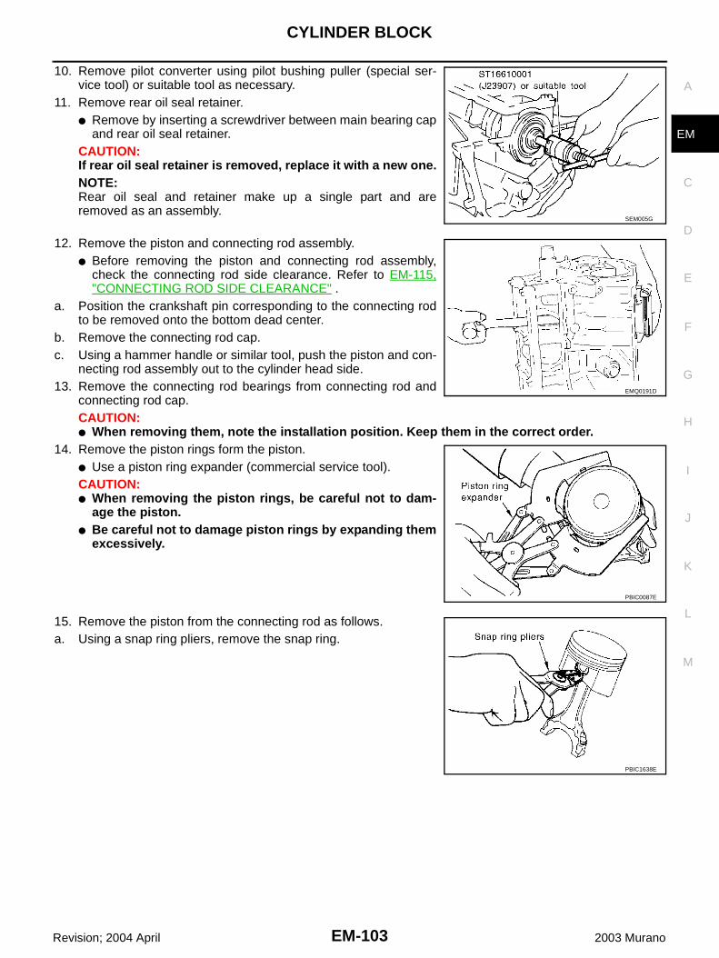
CYLINDER BLOCK
EM-103
C
D
E
F
G
H
I
J
K
L
M
A
EM
Revision; 2004 April 2003 Murano
10. Remove pilot converter using pilot bushing puller (special ser-vice tool) or suitable tool as necessary.
11. Remove rear oil seal retainer.● Remove by inserting a screwdriver between main bearing cap
and rear oil seal retainer.CAUTION:If rear oil seal retainer is removed, replace it with a new one.NOTE:Rear oil seal and retainer make up a single part and areremoved as an assembly.
12. Remove the piston and connecting rod assembly.● Before removing the piston and connecting rod assembly,
check the connecting rod side clearance. Refer to EM-115,"CONNECTING ROD SIDE CLEARANCE" .
a. Position the crankshaft pin corresponding to the connecting rodto be removed onto the bottom dead center.
b. Remove the connecting rod cap.c. Using a hammer handle or similar tool, push the piston and con-
necting rod assembly out to the cylinder head side.13. Remove the connecting rod bearings from connecting rod and
connecting rod cap.CAUTION:● When removing them, note the installation position. Keep them in the correct order.
14. Remove the piston rings form the piston. ● Use a piston ring expander (commercial service tool).CAUTION:● When removing the piston rings, be careful not to dam-
age the piston.● Be careful not to damage piston rings by expanding them
excessively.
15. Remove the piston from the connecting rod as follows. a. Using a snap ring pliers, remove the snap ring.
SEM005G
EMQ0191D
PBIC0087E
PBIC1638E

EM-104
CYLINDER BLOCK
Revision; 2004 April 2003 Murano
b. Heat piston to 60 to 70°C (140 to 158°F) with drier or equivalent.
c. Push out piston pin with stick of outer diameter approximately 20mm (0.79 in).
16. Remove main bearing cap bolt.NOTE:Use TORX socket (size E14).● Before loosening main bearing cap bolts, measure crankshaft
side clearance. Refer to EM-115, "CRANKSHAFT SIDECLEARANCE" .
● Loosen them in the numerical order shown in the figure inseveral different steps.
17. Remove main bearing beam.18. Remove main bearing cap.
● Using main bearing cap bolts, remove main bearing cap whileshaking it back-and-forth.
19. Remove crankshaft.20. Remove main bearings and thrust bearings from cylinder block
and main bearing cap.CAUTION:Identify installation positions, and store them without mix-ing them up.
21. Remove oil jet.
ASSEMBLY1. Fully air-blow the coolant and oil passages in the cylinder block, the cylinder bore and the crankcase to
remove any foreign material.CAUTION:Use a goggles to protect your eye.
PBIC1639E
PBIC0262E
PBIC0909E
EMQ0195D

CYLINDER BLOCK
EM-105
C
D
E
F
G
H
I
J
K
L
M
A
EM
Revision; 2004 April 2003 Murano
2. Install each plug to the cylinder block.● Apply liquid gasket.
Use Genuine Thread Sealant or equivalent. Refer to GI-46,"RECOMMENDED CHEMICAL PRODUCTS AND SEAL-ANTS" .
3. Install oil jet.● Insert oil jet dowel pin into the cylinder block dowel pin hole,
and tighten the mounting bolts.
4. Install the main bearings and the thrust bearings.a. Remove dust, dirt, and oil on the bearing mating surfaces of the
cylinder block and the main bearing cap.b. Install the thrust bearings to the both sides of the No. 3 journal
housing on the cylinder block and the main bearing cap.● Install the thrust bearings with the oil groove facing the crank-
shaft arm (outside). ● Install bearing with a projection on one end on cylinder block,
and bearing with a projection at center on cap. Align each pro-jection with mating notch.
c. Install the main bearings paying attention to the direction.● The main bearing with an oil hole and groove goes on the cyl-
inder block. The one without them goes on the main bearingcap.
● Before installing the bearings, apply engine oil to the bearingsurface (inside). Do not apply oil to the back surface, but thor-oughly clean it.
● When installing, align the bearing stopper to the notch.● Ensure the oil holes on cylinder block and those on the corre-
sponding bearing are aligned.
Part Washer Tightening torque
A No 7.8 - 11.8 N·m (0.8 - 1.2 kg-m, 69 - 104 in-lb)
B Yes 24.5 - 29.4 N·m (2.5 - 2.9 kg-m, 18 - 21 ft-lb)
C Yes 59 - 65 N·m (6.1 - 6.7 kg-m, 44 - 48 ft-lb)
PBIC1269E
PBIC0898E
PBIC0807E
SEM175F

EM-106
CYLINDER BLOCK
Revision; 2004 April 2003 Murano
5. Install the crankshaft to the cylinder block.● While turning the crankshaft by hand, check that it turns
smoothly. 6. Install main bearing cap.
● Main bearing caps are identified by identification mark cast onthem. For installation, face front mark to front side.NOTE:Main bearing cap cannot be replaced as a single part,because it is machined together with cylinder block.
7. Install main bearing beam.● Install main bearing beam with front mark facing downward
(oil pan side).● Install main bearing beam with front mark facing front of
engine.8. Inspect outer diameter of main bearing cap bolt. Refer to EM-
123, "OUTER DIAMETER OF MAIN BEARING CAP BOLT" .
9. Install main bearing cap bolt.a. Apply new engine oil to threads and seat surfaces of mounting
bolts.b. Tighten bolts in numerical order with tightening torque 32.3 to
38.3 N·m (3.3 to 3.9 kg-m, 24 to 28 ft-lb) in several differentsteps.
c. Turn all bolts another 90 to 95 degrees clockwise [Target: 90degrees (Angle tightening)].CAUTION:Use an angle wrench [special service tool: KV10112100(BT8653-A)] to check tightening angle. Do not make judg-ment by visual inspection. ● After installing mounting bolts, make sure that crankshaft can
be rotated smoothly by hand.● Check crankshaft side clearance. Refer to EM-115, "CRANK-
SHAFT SIDE CLEARANCE" .10. Inspect outer diameter of connecting rod bolt. Refer to EM-123,
"OUTER DIAMETER OF CONNECTING ROD BOLT" .11. Install the piston to the connecting rod. a. Using a snap ring pliers, install a new snap ring to the groove of the piston rear side.
● Insert it fully into groove to install.b. Install the piston to the connecting rod.
● Using an industrial drier or similar tool, heat the piston until the piston pin can be pushed in by handwithout excess force [approx. 60 to 70 °C (140 to 158 °F)]. From the front to the rear, insert the pistonpin into the piston and the connecting rod.
SEM456G
PBIC0881E
SEM851E
PBIC0921E
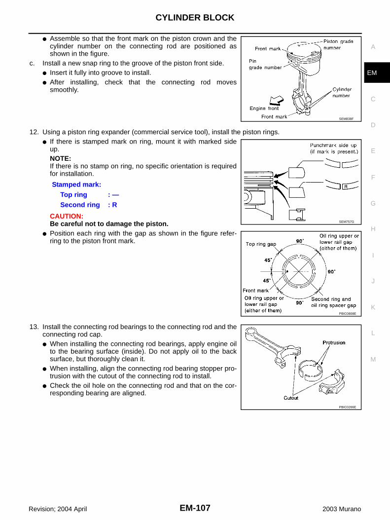
CYLINDER BLOCK
EM-107
C
D
E
F
G
H
I
J
K
L
M
A
EM
Revision; 2004 April 2003 Murano
● Assemble so that the front mark on the piston crown and thecylinder number on the connecting rod are positioned asshown in the figure.
c. Install a new snap ring to the groove of the piston front side. ● Insert it fully into groove to install.● After installing, check that the connecting rod moves
smoothly.
12. Using a piston ring expander (commercial service tool), install the piston rings.● If there is stamped mark on ring, mount it with marked side
up.NOTE:If there is no stamp on ring, no specific orientation is requiredfor installation.
CAUTION:Be careful not to damage the piston.
● Position each ring with the gap as shown in the figure refer-ring to the piston front mark.
13. Install the connecting rod bearings to the connecting rod and theconnecting rod cap.● When installing the connecting rod bearings, apply engine oil
to the bearing surface (inside). Do not apply oil to the backsurface, but thoroughly clean it.
● When installing, align the connecting rod bearing stopper pro-trusion with the cutout of the connecting rod to install.
● Check the oil hole on the connecting rod and that on the cor-responding bearing are aligned.
SEM838F
Stamped mark:Top ring : —Second ring : R
SEM757G
PBIC0808E
PBIC0266E
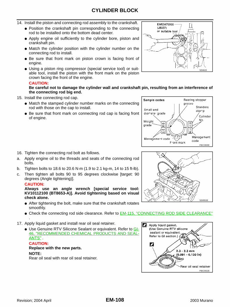
EM-108
CYLINDER BLOCK
Revision; 2004 April 2003 Murano
14. Install the piston and connecting rod assembly to the crankshaft. ● Position the crankshaft pin corresponding to the connecting
rod to be installed onto the bottom dead center. ● Apply engine oil sufficiently to the cylinder bore, piston and
crankshaft pin. ● Match the cylinder position with the cylinder number on the
connecting rod to install. ● Be sure that front mark on piston crown is facing front of
engine.● Using a piston ring compressor (special service tool) or suit-
able tool, install the piston with the front mark on the pistoncrown facing the front of the engine.CAUTION:Be careful not to damage the cylinder wall and crankshaft pin, resulting from an interference ofthe connecting rod big end.
15. Install the connecting rod cap.● Match the stamped cylinder number marks on the connecting
rod with those on the cap to install. ● Be sure that front mark on connecting rod cap is facing front
of engine.
16. Tighten the connecting rod bolt as follows.a. Apply engine oil to the threads and seats of the connecting rod
bolts. b. Tighten bolts to 18.6 to 20.6 N·m (1.9 to 2.1 kg-m, 14 to 15 ft-lb).c. Then tighten all bolts 90 to 95 degrees clockwise [target: 90
degrees (Angle tightening)].CAUTION:Always use an angle wrench [special service tool:KV10112100 (BT8653-A)]. Avoid tightening based on visualcheck alone.● After tightening the bolt, make sure that the crankshaft rotates
smoothly.● Check the connecting rod side clearance. Refer to EM-115, "CONNECTING ROD SIDE CLEARANCE"
.17. Apply liquid gasket and install rear oil seal retainer.
● Use Genuine RTV Silicone Sealant or equivalent. Refer to GI-46, "RECOMMENDED CHEMICAL PRODUCTS AND SEAL-ANTS" .CAUTION:Replace with the new parts.NOTE:Rear oil seal with rear oil seal retainer.
SEM620
PBIC0809E
SEM953E
PBIC0922E

CYLINDER BLOCK
EM-109
C
D
E
F
G
H
I
J
K
L
M
A
EM
Revision; 2004 April 2003 Murano
18. Install pilot converter using suitable tool.● Outer diameter of drift
● Press-fit pilot converter with its chamfer facing crankshaft.
● Install pilot converter as shown.
19. Install drive plate.● Install drive plate and reinforcement plate as shown in figure.● Secure the crankshaft using a suitable ring gear stopper or an
alternative manner.● Tighten the installation bolts crosswise over several times.
20. Install knock sensor.● Make sure that there is no foreign material on the cylinder
block mating surface and the back surface of the knock sen-sor.
● Install knock sensor so that connector faces front of engine.● Do not tighten the mounting bolts while holding the connector. ● Make sure that the knock sensor does not interfere with other-
parts.CAUTION:If any impact by dropping is applied to the knock sensor,replace it with new one.
● After installing knock sensor, connect sub-harness, and lay it out to rear of engine.21. Install followings in reverse order of removal.
Pilot converter : Approx. 33 mm (1.30 in)
PBIC0899E
SEM537E
PBIC0910E
PBIC0810E
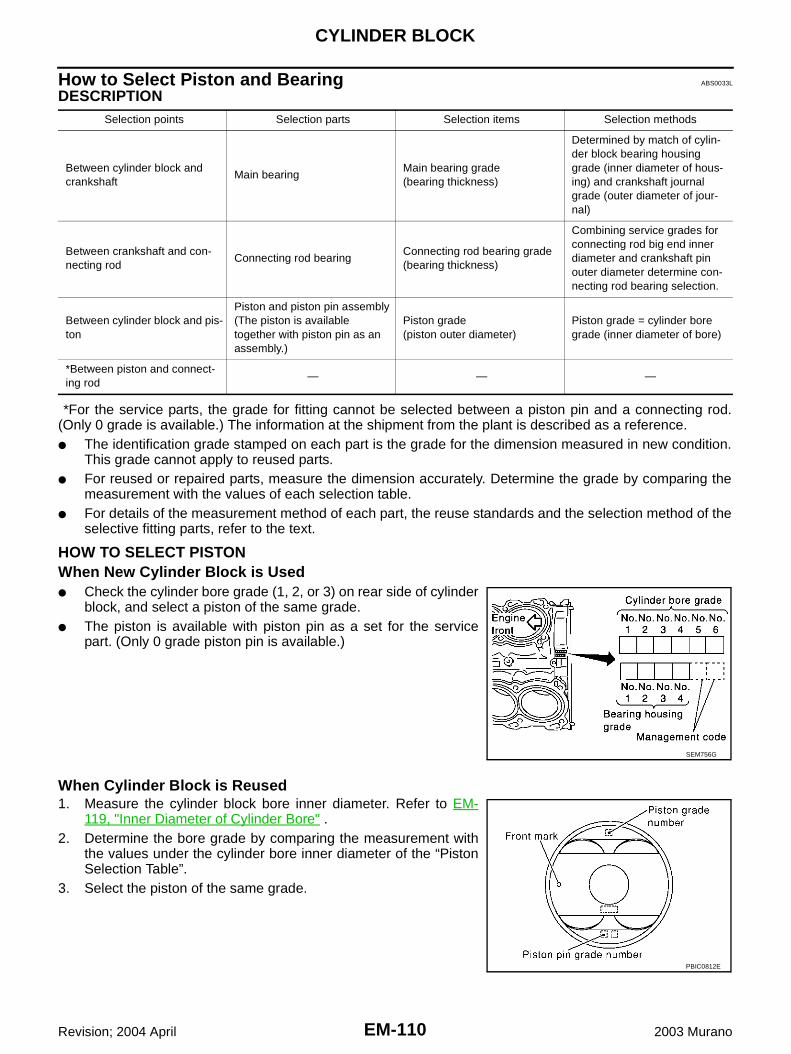
EM-110
CYLINDER BLOCK
Revision; 2004 April 2003 Murano
How to Select Piston and Bearing ABS0033L
DESCRIPTION
*For the service parts, the grade for fitting cannot be selected between a piston pin and a connecting rod.(Only 0 grade is available.) The information at the shipment from the plant is described as a reference.● The identification grade stamped on each part is the grade for the dimension measured in new condition.
This grade cannot apply to reused parts.● For reused or repaired parts, measure the dimension accurately. Determine the grade by comparing the
measurement with the values of each selection table.● For details of the measurement method of each part, the reuse standards and the selection method of the
selective fitting parts, refer to the text.
HOW TO SELECT PISTONWhen New Cylinder Block is Used● Check the cylinder bore grade (1, 2, or 3) on rear side of cylinder
block, and select a piston of the same grade.● The piston is available with piston pin as a set for the service
part. (Only 0 grade piston pin is available.)
When Cylinder Block is Reused1. Measure the cylinder block bore inner diameter. Refer to EM-
119, "Inner Diameter of Cylinder Bore" .2. Determine the bore grade by comparing the measurement with
the values under the cylinder bore inner diameter of the “PistonSelection Table”.
3. Select the piston of the same grade.
Selection points Selection parts Selection items Selection methods
Between cylinder block and crankshaft
Main bearingMain bearing grade(bearing thickness)
Determined by match of cylin-der block bearing housing grade (inner diameter of hous-ing) and crankshaft journal grade (outer diameter of jour-nal)
Between crankshaft and con-necting rod
Connecting rod bearingConnecting rod bearing grade (bearing thickness)
Combining service grades for connecting rod big end inner diameter and crankshaft pin outer diameter determine con-necting rod bearing selection.
Between cylinder block and pis-ton
Piston and piston pin assembly(The piston is available together with piston pin as an assembly.)
Piston grade(piston outer diameter)
Piston grade = cylinder bore grade (inner diameter of bore)
*Between piston and connect-ing rod
— — —
SEM756G
PBIC0812E

CYLINDER BLOCK
EM-111
C
D
E
F
G
H
I
J
K
L
M
A
EM
Revision; 2004 April 2003 Murano
Piston Selection TableUnit: mm (in)
NOTE:● The piston is available together with piston pin as an assembly.● The piston pin (piston pin bore) grade is provided only for the parts installed at the plant. For service parts,
no piston pin grades can be selected. (Only 0 grade is available.)● No second grade mark is available on piston.
HOW TO SELECT CONNECTING ROD BEARINGWhen New Connecting Rod and Crankshaft are Used● Check pin diameter grade number (0, 1, or 2) stamped in front of
crankshaft, and select connecting rod bearing of same gradenumber.NOTE:There is no grading for connecting rod big end inner diameter.
When Crankshaft and Connecting Rod are Reused1. Measure dimensions of the big end inner diameter of connecting rod and outer diameter of crankshaft pin
individually. Refer to EM-117, "CONNECTING ROD BEARING HOUSING DIAMETER (BIG END)" andEM-120, "OUTER DIAMETER OF CRANKSHAFT PIN" .
2. Confirm the big end inner diameter of connecting rod is within the standard value.3. Apply the measured dimension to the “Connecting Rod Bearing Selection Table”.4. Determine the grade of crankshaft pin diameter grade by comparing the measurement with the values
under the crankshaft pin outer diameter of the “Connecting Rod Bearing Selection Table”.5. Select the connecting rod bearing of the same grade.
Connecting Rod Bearing Selection TableUnit: mm (in)
Undersize Bearings Usage Guide● When the specified oil clearance is not obtained with standard size connecting rod bearings, use under-
size (US) bearings.● When using undersize bearing, measure the bearing inner diameter with bearing installed, and grind the
crankshaft pin so that the oil clearance satisfies the standard.
Grade 1 2 (or no mark) 3
Inner diameter of cylinder bore95.500 / 95.510
(3.7598 / 3.7602)95.510 / 95.520
(3.7602 / 3.7606)95.520 / 95.530
(3.7606 / 3.7610)
Outer diameter of piston95.480 / 95.490
(3.7590 / 3.7594)95.490 / 95.500
(3.7594 / 3.7598)95.500 / 95.510
(3.7598 / 3.7602)
SEM452G
Connecting rod big end inner diameter (Standard value) 55.000 - 55.013 (2.1654 - 2.1659)
Crankshaft pin outer diameter Grade (Mark) — (No grade)
51.968 - 51.974(2.0460 - 2.0462)
0Bearing grade No. STD 0 Bearing thickness range: 1.500 - 1.503 (0.00591 - 0.0592)Color: Black
51.962 - 51.968 (2.0457 - 2.0460)
1Bearing grade No. STD 1Bearing thickness range: 1.503 - 1.506 (0.0592 - 0.0593)Color: Brown
51.956 - 51.962(2.0455 - 2.0457)
2Bearing grade No. STD 2Bearing thickness range: 1.506 - 1.509 (0.0593 - 0.0594)Color: Green
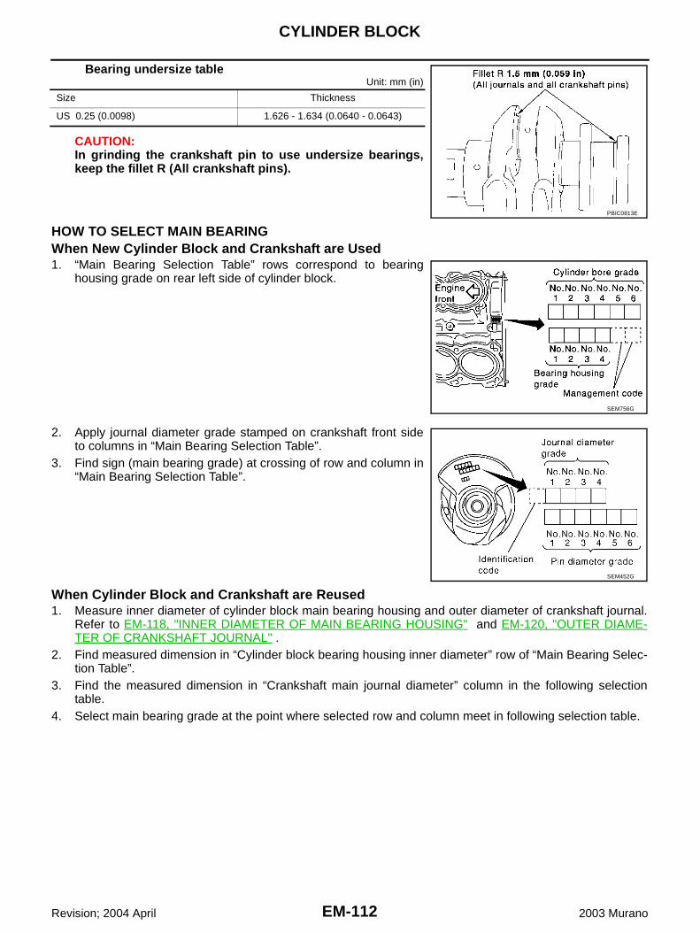
EM-112
CYLINDER BLOCK
Revision; 2004 April 2003 Murano
Bearing undersize tableUnit: mm (in)
CAUTION:In grinding the crankshaft pin to use undersize bearings,keep the fillet R (All crankshaft pins).
HOW TO SELECT MAIN BEARINGWhen New Cylinder Block and Crankshaft are Used1. “Main Bearing Selection Table” rows correspond to bearing
housing grade on rear left side of cylinder block.
2. Apply journal diameter grade stamped on crankshaft front sideto columns in “Main Bearing Selection Table”.
3. Find sign (main bearing grade) at crossing of row and column in“Main Bearing Selection Table”.
When Cylinder Block and Crankshaft are Reused1. Measure inner diameter of cylinder block main bearing housing and outer diameter of crankshaft journal.
Refer to EM-118, "INNER DIAMETER OF MAIN BEARING HOUSING" and EM-120, "OUTER DIAME-TER OF CRANKSHAFT JOURNAL" .
2. Find measured dimension in “Cylinder block bearing housing inner diameter” row of “Main Bearing Selec-tion Table”.
3. Find the measured dimension in “Crankshaft main journal diameter” column in the following selectiontable.
4. Select main bearing grade at the point where selected row and column meet in following selection table.
Size Thickness
US 0.25 (0.0098) 1.626 - 1.634 (0.0640 - 0.0643)
PBIC0813E
SEM756G
SEM452G

CYLINDER BLOCK
EM-113
C
D
E
F
G
H
I
J
K
L
M
A
EM
Revision; 2004 April 2003 Murano
Main Bearing Selection Table
PBIC0814E

EM-114
CYLINDER BLOCK
Revision; 2004 April 2003 Murano
Main Bearing Grade Table (All Journals)
Undersize Bearing Usage Guide● Use undersize (US) bearing when oil clearance with standard
size main bearing is not within specification.● When using undersize (US) bearing, measure the bearing inner
diameter with bearing installed, and grind journal until oil clear-ance falls within specification.Bearing undersize table
Unit: mm (in)
CAUTION:Keep fillet R when grinding crankshaft journal in order touse undersize bearing (All journals).
Grade number Thickness “T” mm (in) Width “W” mm (in)Identification color
(UPR/LWR)Remarks
0 2.000 - 2.003 (0.0787 - 0.0789)
19.9 - 20.1 (0.783 - 0.791)
Black
Grade is the same for upper and lower bear-ings.
1 2.003 - 2.006 (0.0789 - 0.0790) Brown
2 2.006 - 2.009 (0.0790 - 0.0791) Green
3 2.009 - 2.012 (0.0791 - 0.0792) Yellow
4 2.012 - 2.015 (0.0792 - 0.0793) Blue
5 2.015 - 2.018 (0.0793 - 0.0794) Pink
6 2.018 - 2.021 (0.0794 - 0.0796) Purple
7 2.021 - 2.024 (0.0796 - 0.0797) White
01UPP 2.003 - 2.006 (0.0789 - 0.0790)
Brown/Black
Grade is different for upper and lower bear-ings.
LWR 2.000 - 2.003 (0.0787 - 0.0789)
12UPR 2.006 - 2.009 (0.0790 - 0.0791)
Green/BrownLWR 2.003 - 2.006 (0.0789 - 0.0790)
23UPR 2.009 - 2.012 (0.0791 - 0.0792)
Yellow/GreenLWR 2.006 - 2.009 (0.0790 - 0.0791)
34UPR 2.012 - 2.015 (0.0792 - 0.0793)
Blue/YellowLWR 2.009 - 2.012 (0.0791 - 0.0792)
45UPR 2.015 - 2.018 (0.0793 - 0.0794)
Pink/BlueLWR 2.012 - 2.015 (0.0792 - 0.0793)
56UPR 2.018 - 2.021 (0.0794 - 0.0796)
Purple/PinkLWR 2.015 - 2.018 (0.0793 - 0.0794)
67UPR 2.021 - 2.024 (0.0796 - 0.0797)
White/PurpleLWR 2.018 - 2.021 (0.0794 - 0.0796)
Size Thickness
US 0.25 (0.0098) 2.132 - 2.140 (0.0839 - 0.0843)
PBIC0813E
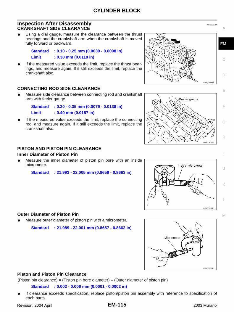
CYLINDER BLOCK
EM-115
C
D
E
F
G
H
I
J
K
L
M
A
EM
Revision; 2004 April 2003 Murano
Inspection After Disassembly ABS0033M
CRANKSHAFT SIDE CLEARANCE● Using a dial gauge, measure the clearance between the thrust
bearings and the crankshaft arm when the crankshaft is movedfully forward or backward.
● If the measured value exceeds the limit, replace the thrust bear-ings, and measure again. If it still exceeds the limit, replace thecrankshaft also.
CONNECTING ROD SIDE CLEARANCE● Measure side clearance between connecting rod and crankshaft
arm with feeler gauge.
● If the measured value exceeds the limit, replace the connectingrod, and measure again. If it still exceeds the limit, replace thecrankshaft also.
PISTON AND PISTON PIN CLEARANCEInner Diameter of Piston Pin● Measure the inner diameter of piston pin bore with an inside
micrometer.
Outer Diameter of Piston Pin● Measure outer diameter of piston pin with a micrometer.
Piston and Piston Pin Clearance(Piston pin clearance) = (Piston pin bore diameter) – (Outer diameter of piston pin)
● If clearance exceeds specification, replace piston/piston pin assembly with reference to specification ofeach parts.
Standard : 0.10 - 0.25 mm (0.0039 - 0.0098 in)Limit : 0.30 mm (0.0118 in)
EMQ0196D
Standard : 0.20 - 0.35 mm (0.0079 - 0.0138 in)Limit : 0.40 mm (0.0157 in)
PBIC0815E
Standard : 21.993 - 22.005 mm (0.8659 - 0.8663 in)
PBIC0116E
Standard : 21.989 - 22.001 mm (0.8657 - 0.8662 in)
PBIC0117E
Standard : 0.002 - 0.006 mm (0.0001 - 0.0002 in)

EM-116
CYLINDER BLOCK
Revision; 2004 April 2003 Murano
● When replacing piston/piston pin assembly, refer to EM-119, "PISTON TO CYLINDER BORE CLEAR-ANCE" .
PISTON RING SIDE CLEARANCE● Measure side clearance of piston ring and piston ring groove
with feeler gauge.
● If out of specification, replace piston and/or piston ring assembly.
PISTON RING END GAP● Check if inner diameter of cylinder bore is within specification.
Refer to EM-119, "PISTON TO CYLINDER BORE CLEAR-ANCE" .
● Insert piston ring until middle of cylinder with piston, and mea-sure gap.
● If out of specification, replace piston ring. If gap still exceeds the limit even with a new ring, re-bore cylin-der and use oversized piston and piston ring.
CONNECTING ROD BEND AND TORSION● Check with connecting rod aligner.
Standard:Top ring : 0.045 - 0.080 mm (0.0016 - 0.0031 in)2nd ring : 0.030 - 0.070 mm (0.0012 - 0.0028 in)Oil ring : 0.065 - 0.135 mm (0.0026 - 0.0053 in)
Limit: Top ring : 0.11 mm (0.0043 in) 2nd ring : 0.1 mm (0.004 in) SEM024AA
Standard:Top ring : 0.23 - 0.33 mm (0.0091 - 0.0130 in)2nd ring : 0.33 - 0.48 mm (0.0130 - 0.0189 in)Oil ring : 0.20 - 0.50 mm (0.0079 - 0.0197 in)
Limit: Top ring : 0.54 mm (0.0213 in) 2nd ring : 0.80 mm (0.0315 in)
Oil ring : 0.95 mm (0.0374 in)
PBIC0118E
Bend:Limit : 0.15 mm (0.0059 in) per 100 mm (3.94 in) length
Torsion:Limit : 0.30 mm (0.0118 in) per 100 mm (3.94 in) length
SEM038F

CYLINDER BLOCK
EM-117
C
D
E
F
G
H
I
J
K
L
M
A
EM
Revision; 2004 April 2003 Murano
● If it exceeds the limit, replace connecting rod assembly.
CONNECTING ROD BEARING HOUSING DIAMETER (BIG END)● Install the connecting rod cap without the connecting rod bearing
installed. After tightening the connecting rod bolt to the specifiedtorque, measure the connecting rod big end inner diameterusing an inside micrometer. Refer to EM-104, "ASSEMBLY" forthe tightening procedure.
● If it exceeds the standard, replace the connecting rod.
CONNECTING ROD BUSHING OIL CLEARANCE (SMALL END)Inner Diameter of Connecting Rod (Small End)● Measure inner diameter of bushing.
Outer Diameter of Piston Pin● Measure outer diameter of piston pin.
SEM003F
Standard : 55.000 - 55.013 mm (2.1654 - 2.1659 in)
PBIC1641E
Standard : 22.000 - 22.012 mm (0.8661 - 0.8666 in)
PBIC0120E
Standard : 21.989 - 22.001 mm (0.8657 - 0.8662 in)
PBIC0117E

EM-118
CYLINDER BLOCK
Revision; 2004 April 2003 Murano
Connecting Rod Bushing Oil Clearance (Small End)(Connecting rod small end oil clearance) = (Inner diameter of con-necting rod small end) – (Outer diameter of piston pin)
● If the measured value exceeds the standard, replace the con-necting rod assembly and/or piston and piston pin assembly.
● If replacing the piston and piston pin assembly, refer to EM-119,"PISTON TO CYLINDER BORE CLEARANCE" .
● If replacing the connecting rod assembly, refer to EM-121, "OILCLEARANCE OF CONNECTING ROD BEARING" .
Factory installed parts grading:● Service parts apply only to grade 0.
Unit: mm (in)
CYLINDER BLOCK DISTORTION● Using a scraper, remove gasket on the cylinder block surface,
and also remove oil, scale, carbon, or other contamination. CAUTION:Be careful not to allow gasket flakes to enter the oil orengine coolant passages.
● Measure the distortion on the block upper face at some differentpoints in 6 directions.
● If out of the distortion limit, replace the cylinder block.
INNER DIAMETER OF MAIN BEARING HOUSING● Install the main bearing caps and main bearing beam with the
main bearings removed, and tighten the mounting bolts to thespecified torque. Refer to EM-104, "ASSEMBLY" for the tighten-ing procedure.
● Using a bore gauge, measure the inner diameter of the mainbearing housing.
● If out of specification, replace cylinder block and main bearingcaps as an assembly.NOTE:Cylinder block cannot be replaced as a single part because it ismachined together with main bearing cap.
Standard : 0.005 - 0.017 mm (0.0002 - 0.0007 in)Limit : 0.030 mm (0.0012 in)
PBIC0809E
Grade 0 1
Connecting rod small end inner diameter
22.000 - 22.006 (0.8661 - 0.8664)
22.006 - 22.012 (0.8664 - 0.8666)
Piston pin bore diameter 21.993 - 21.999 (0.8659 - 0.8661)
21.999 - 22. 005 (0.8661 - 0.8663)
Piston pin outer diameter 21.989 - 21.995 (0.8657- 0.8659)
21.995 - 22.001 (0.8659 - 0.8662)
PBIC0812E
Limit : 0.1 mm (0.004 in)
SEM123C
Standard : 63.993 - 64.017 mm (2.5194 - 2.5203 in)
PBIC1643E
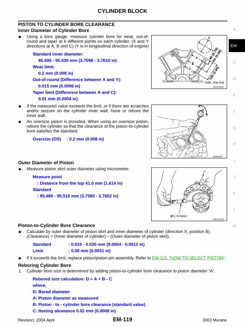
CYLINDER BLOCK
EM-119
C
D
E
F
G
H
I
J
K
L
M
A
EM
Revision; 2004 April 2003 Murano
PISTON TO CYLINDER BORE CLEARANCEInner Diameter of Cylinder Bore● Using a bore gauge, measure cylinder bore for wear, out-of-
round and taper at 6 different points on each cylinder. (X and Ydirections at A, B and C) (Y is in longitudinal direction of engine)
● If the measured value exceeds the limit, or if there are scratchesand/or seizure on the cylinder inner wall, hone or rebore theinner wall.
● An oversize piston is provided. When using an oversize piston,rebore the cylinder so that the clearance of the piston-to-cylinderbore satisfies the standard.
Outer Diameter of Piston● Measure piston skirt outer diameter using micrometer.
Piston-to-Cylinder Bore Clearance● Calculate by outer diameter of piston skirt and inner diameter of cylinder (direction X, position B).
(Clearance) = (Inner diameter of cylinder) – (Outer diameter of piston skirt).
● If it exceeds the limit, replace piston/piston pin assembly. Refer to EM-110, "HOW TO SELECT PISTON" .
Reboring Cylinder Bore1. Cylinder bore size is determined by adding piston-to-cylinder bore clearance to piston diameter “A”.
Standard inner diameter:95.500 - 95.530 mm (3.7598 - 3.7610 in)
Wear limit:0.2 mm (0.008 in)
Out-of-round (Difference between X and Y):0.015 mm (0.0006 in)
Taper limit (Difference between A and C): 0.01 mm (0.0004 in)
Oversize (OS) : 0.2 mm (0.008 in)
PBIC0923E
SEM843E
Measure point: Distance from the top 41.0 mm (1.614 in)
Standard: 95.480 - 95.510 mm (3.7590 - 3.7602 in)
PBIC0125E
Standard : 0.010 - 0.030 mm (0.0004 - 0.0012 in)Limit : 0.08 mm (0.0031 in)
Rebored size calculation: D = A + B - Cwhere,D: Bored diameterA: Piston diameter as measuredB: Piston - to - cylinder bore clearance (standard value)C: Honing allowance 0.02 mm (0.0008 in)

EM-120
CYLINDER BLOCK
Revision; 2004 April 2003 Murano
2. Install main bearing caps and main bearing beam, and tighten to the specified torque. Otherwise, cylinderbores may be distorted in final assembly.
3. Cut cylinder bores.● When any cylinder needs boring, all other cylinders must also be bored.● Do not cut too much out of cylinder bore at a time. Cut only 0.05 mm (0.0020 in) or so in diameter at a
time.4. Hone cylinders to obtain specified piston-to-cylinder bore clearance.5. Measure finished cylinder bore for out-of-round and taper.
● Measurement should be done after cylinder bore cools down.
OUTER DIAMETER OF CRANKSHAFT JOURNAL● Measure outer diameter of crankshaft journals.
● If it out of the standard, measure the main bearing oil clearance.Then use the undersize bearing. Refer to EM-122, "OIL CLEAR-ANCE OF MAIN BEARING" .
OUTER DIAMETER OF CRANKSHAFT PIN● Measure outer diameter of crankshaft pin.
● If it out of the standard, measure the connecting rod bearing oil clearance. Then use the undersize bear-ing. Refer to EM-121, "OIL CLEARANCE OF CONNECTING ROD BEARING" .
OUT-OF-ROUND AND TAPER OF CRANKSHAFT● Using a micrometer, measure the dimensions at 4 different
points shown in the figure on each journal and pin. ● Out-of-round is indicated by the difference in dimensions
between X and Y at A and B.● Taper is indicated by the difference in dimension between A and
B at X and Y.
● If the measured value exceeds the limit, correct or replace the crankshaft.● If corrected, measure the bearing oil clearance of the corrected journal or pin. Then select the main bear-
ing or connecting rod bearing. Refer to EM-122, "OIL CLEARANCE OF MAIN BEARING" or EM-121,"OIL CLEARANCE OF CONNECTING ROD BEARING" .
Standard : 59.951 - 59.975 mm (2.3603 - 2.3612 in) dia.
PBIC0127E
Standard : 51.956 - 51.974 mm (2.0455 - 2.0462 in) dia.
Limit:Out-of-round(Difference between X and Y)
: 0.002 mm (0.0001 in)
Taper(Difference between A and B)
: 0.002 mm (0.0001 in) SEM316A

CYLINDER BLOCK
EM-121
C
D
E
F
G
H
I
J
K
L
M
A
EM
Revision; 2004 April 2003 Murano
CRANKSHAFT RUNOUT ● Place a V-block on a precise flat table to support the journals on
the both end of the crankshaft.● Place a dial gauge straight up on the No. 3 journal. ● While rotating the crankshaft, read the movement of the pointer
on the dial gauge. (Total indicator reading)
● If it exceeds the limit, replace the crankshaft.
OIL CLEARANCE OF CONNECTING ROD BEARINGMethod by Calculation● Install the connecting rod bearings to the connecting rod and the
cap, and tighten the connecting rod bolts to the specified torque.Using a inside micrometer measure the inner diameter of con-necting rod bearing. Refer to EM-104, "ASSEMBLY" for thetightening procedure.(Oil clearance) = (Inner diameter of connecting rod bearing) –(Outer diameter of crankshaft pin)
● If clearance cannot be adjusted within the standard, grind crank-shaft pin and use undersized bearing. Refer toEM-111, "HOW TO SELECT CONNECTING ROD BEAR-ING" .
Method of Using Plastigage● Remove oil and dust on the crankshaft pin and the surfaces of
each bearing completely. ● Cut a plastigage slightly shorter than the bearing width, and
place it in crankshaft axial direction, avoiding oil holes.● Install the connecting rod bearings to the connecting rod and
the cap, and tighten the connecting rod bolts to the specifiedtorque. Refer to EM-104, "ASSEMBLY" for the tightening proce-dure.CAUTION:Never rotate the crankshaft.
● Remove the connecting rod cap and bearings, and using thescale on the plastigage bag, measure the plastigage width. NOTE:The procedure when the measured value exceeds the limit is same as that described in the “Method byCalculation”.
Standard : Less than 0.025 mm (0.0010 in)Limit : 0.10 mm (0.0039 in)
SEM346D
Standard : 0.034 - 0.059 mm (0.0013 - 0.0023 in) (actual clearance)
Limit : 0.070 mm (0.0028 in)PBIC1642E
PBIC1149E

EM-122
CYLINDER BLOCK
Revision; 2004 April 2003 Murano
OIL CLEARANCE OF MAIN BEARINGMethod by Calculation● Install the main bearings to the cylinder block and bearing cap.
Measure the main bearing inner diameter with the bearing capbolt tightened with main bearing beam to the specified torque.Refer to EM-104, "ASSEMBLY" for the tightening procedure.(Oil clearance) = (Inner diameter of main bearing) – (Outerdiameter of crankshaft journal)
● If the measured value exceeds the limit, select main bearingsreferring to the main bearing inner diameter and crankshaft jour-nal outer diameter, so that the oil clearance satisfies the standard. Refer to EM-112, "HOW TO SELECTMAIN BEARING" .
Method of Using Plastigage● Remove oil and dust on the crankshaft journal and the surfaces
of each bearing completely.● Cut a plastigage slightly shorter than the bearing width, and
place it in crankshaft axial direction, avoiding oil holes.● Tighten the main bearing bolts with main bearing beam to the
specified torque. Refer to EM-104, "ASSEMBLY" for the tighten-ing procedure.CAUTION:Never rotate the crankshaft.
● Remove the bearing cap and bearings, and using the scale onthe plastigage bag, measure the plastigage width. NOTE:The procedure when the measured value exceeds the limit is same as that described in the “Method byCalculation”.
CRUSH HEIGHT OF MAIN BEARING● When the main bearing cap is removed after being tightened to
the specified torque with main bearings installed, the tip end ofbearing must protrude. Refer to EM-104, "ASSEMBLY" for thetightening procedure.
● If the standard is not met, replace main bearings.
CRUSH HEIGHT OF CONNECTING ROD BEARING● When the connecting rod bearing cap is removed after being
tightened to the specified torque with connecting rod bearingsinstalled, the tip end of bearing must protrude. Refer to EM-104,"ASSEMBLY" for the tightening procedure.
● If the standard is not met, replace connecting rod bearings.
Standard : 0.035 - 0.045 mm (0.0014 - 0.0018 in) (actual clearance)
Limit : 0.065 mm (0.0026 in)
PBIC1644E
PBIC1149E
Standard : There must be crush height.
SEM502G
Standard : There must be crush height.
PBIC1646E

CYLINDER BLOCK
EM-123
C
D
E
F
G
H
I
J
K
L
M
A
EM
Revision; 2004 April 2003 Murano
OUTER DIAMETER OF MAIN BEARING CAP BOLT● Measure outer diameters (d1, d2) at two positions shown in the
figure.● Measure d2 at a point within block A.
● When the value of d1- d2 exceeds the limit (a large difference indimensions), replace the bolt with a new one.
OUTER DIAMETER OF CONNECTING ROD BOLT● Measure outer diameter “d” at position shown in the figure.
● When “d” exceeds the limit (when it becomes thinner), replacethe bolt with a new one.
SIGNAL PLATE ● Check the drive plate and signal plate for deformation or cracks.
OIL JET● Check nozzle for deformation and damage.● Blow compressed air from nozzle, and check for clogs.● If it is not satisfied, clean or replace oil jet.
OIL JET RELIEF VALVE● Using a clean plastic stick, press check valve in oil jet relief
valve. Make sure that valve moves smoothly with proper reac-tion force.
● If it is not satisfied, replace oil jet relief valve.
Limit : 0.11 mm (0.0051 in)
PBIC0911E
Standard : 7.90 - 8.00 mm (0.3110 - 0.3150 in)Limit : 7.75 mm (0.3051 in)
PBIC0912E
SEM760G
EMU0468D

EM-124
SERVICE DATA AND SPECIFICATIONS (SDS)
Revision; 2004 April 2003 Murano
SERVICE DATA AND SPECIFICATIONS (SDS) PFP:00100
Standard and Limit ABS0033N
GENERAL SPECIFICATIONS
INTAKE MANIFOLD COLLECTOR, INTAKE MANIFOLD AND EXHAUST MANIFOLDUnit: mm (in)
Cylinder arrangement V-6
Displacement cm3 (cu in) 3,498 (213.45)
Bore and stroke mm (in) 95.5 x 81.4 (3.76 x 3.205)
Valve arrangement DOHC
Firing order 1-2-3-4-5-6
Number of piston ringsCompression 2
Oil 1
Number of main bearings 4
Compression ratio 10.3
Compression pressure
kPa (kg/cm2 , psi)/300 rpm
Standard 1,275 (13.0, 185)
Minimum 981 (10.0, 142)
Differential limit between cylinders
98 (1.0, 14)
Cylinder number
Valve timing(Intake valve timing control - OFF)
Unit: degree
a b c d e f
240 238 - 6 64 8 52
SEM713A
PBIC0187E
Limit
Surface distortion
Intake manifold collector upper 0.1 (0.004)
Intake manifold collector lower 0.1 (0.004)
Intake manifold 0.1 (0.004)
Exhaust manifold 0.3 (0.012)

SERVICE DATA AND SPECIFICATIONS (SDS)
EM-125
C
D
E
F
G
H
I
J
K
L
M
A
EM
Revision; 2004 April 2003 Murano
DRIVE BELT
*: If belt tension gauge cannot be installed at check points shown, check drive belt tension at different location on the belt.
SPARK PLUG
CYLINDER HEADUnit: mm (in)
Deflection adjustment Unit: mm (in) Tension adjustment* Unit: N (kg, lb)
Used beltNew belt
Used beltNew belt
Limit After adjustment Limit After adjustment
Alternator and air conditioning compressor
7 (0.28) 4.2 - 4.6 (0.17 - 0.18)
3.7 - 4.1 (0.15 - 0.16)
294 (30, 66)730 - 818
(74.5 - 83.5,164 - 184)
838 - 926(85.5 - 94.5,188 - 208)
Power steering oil pump
11 (0.43) 7.3 - 8 (0.29 - 0.30)
6.5 - 7.2 (0.26 - 0.28)
196 (20, 44)495 - 583
(50.5 - 59.5,111 - 131)
603 - 691(61.5 - 70.5,
135.6 - 155.4)
Applied pushing force
98 N (10 kg, 22 lb) —
PBIC1161E
Make NGK
Standard type PLFR5A-11
Hot type PLFR4A-11
Cold type PLFR6A-11
Gap (nominal) 1.1 mm (0.043 in)
Limit
Head surface distortion 0.1 (0.004)
Normal cylinder head height “H” 126.3 - 126.5 (4.972 - 4.980)
PBIC0924E

EM-126
SERVICE DATA AND SPECIFICATIONS (SDS)
Revision; 2004 April 2003 Murano
VALVEValve Dimensions
Unit: mm (in)
Valve ClearanceUnit: mm (in)
*: Approximately 80°C (176°F)
Valve Spring
Valve LifterUnit: mm (in)
Valve head diameter “D” Intake 37.0 - 37.3 (1.4567 - 1.4685)
Exhaust 31.2 - 31.5 (1.228 - 1.240)
Valve length “L”Intake 96.46 (3.7976)
Exhaust 93.99 (3.7004)
Valve stem diameter “d”Intake 5.965 - 5.980 (0.2348 - 0.2354)
Exhaust 5.955 - 5.970 (0.2344 - 0.2350)
Valve seat angle “α”Intake
45°15′ - 45°45′Exhaust
Valve margin “T”Intake 1.1 (0.043)
Exhaust 1.3 (0.051)
Valve margin “T” limit More than 0.5 (0.020)
Valve stem end surface grinding limit Less than 0.2 (0.008)
SEM188
Cold Hot* (reference data)
Intake 0.26 - 0.34 (0.010 - 0.013) 0.304 - 0.416 (0.012 - 0.016)
Exhaust 0.29 - 0.37 (0.011 - 0.015) 0.308 - 0.432 (0.012 - 0.017)
Free height mm (in) 45.62 (1.7961)
Pressure N (kg, lb) at height mm (in)Installation 184 - 208 (18.8 - 21.2, 41.4 - 46.8) at 37.0 (1.4567)
Valve open 407 - 459 (41.5 - 46.8, 91.5 - 103.2) at 27.8 (1.0945)
Out-of-square mm (in) Less than 2.0 (0.079)
Valve lifter outer diameter 33.977 - 33.987 (1.3377 - 1.3381)
Lifter guide inner diameter 34.000 - 34.016 (1.3386 - 1.3392)
Clearance between lifter and lifter guide 0.013 - 0.039 (0.0005 - 0.0015)

SERVICE DATA AND SPECIFICATIONS (SDS)
EM-127
C
D
E
F
G
H
I
J
K
L
M
A
EM
Revision; 2004 April 2003 Murano
Available Valve LifterUnit: mm (in)
Identification Mark Thickness
788U or 788R 7.88 (0.3102)
790U or 790R 7.90 (0.3110)
792U or 792R 7.92 (0.3118)
794U or 794R 7.94 (0.3126)
796U or 796R 7.96 (0.3134)
798U or 798R 7.98 (0.3142)
800U or 800R 8.00 (0.3150)
802U or 802R 8.02 (03.157)
804U or 804R 8.04 (0.3165)
806U or 806R 8.06 (0.3173)
808U or 808R 8.08 (0.3181)
810U or 810R 8.10 (0.3189)
812U or 812R 8.12 (0.3197)
814U or 814R 8.14 (0.3205)
816U or 816R 8.16 (0.3213)
818U or 818R 8.18 (0.3220)
820U or 820R 8.20 (0.3228)
822U or 822R 8.22 (0.3236)
824U or 824R 8.24 (0.3244)
826U or 826R 8.26 (0.3252)
828U or 828R 8.28 (0.3260)
830U or 830R 8.30 (0.3268)
832U or 832R 8.32 (0.3276)
834U or 834R 8.34 (0.3283)
836U or 836R 8.36 (0.3291)
838U or 838R 8.38 (0.3299)
840U or 840R 8.40 (0.3307)
SEM758G

EM-128
SERVICE DATA AND SPECIFICATIONS (SDS)
Revision; 2004 April 2003 Murano
Valve GuideUnit: mm (in)
Standard Service
Valve guideOuter diameter 10.023 - 10.034 (0.3946 - 0.3950) 10.223 - 10.234 (0.4025 - 0.4029)
Inner diameter (Finished size) 6.000 - 6.018 (0.2362 - 0.2369)
Cylinder head valve guide hole diameter 9.975 - 9.996 (0.3927 - 0.3935) 10.175 - 10.196 (0.4006 - 0.4014)
Interference fit of valve guide 0.027 - 0.059 (0.0011 - 0.0023)
Standard Max. tolerance
Stem to guide clearanceIntake 0.020 - 0.053 (0.0008 - 0.0021) 0.08 (0.0031)
Exhaust 0.030 - 0.063 (0.0012 - 0.0025) 0.09 (0.004)
Projection length “L” 12.6 - 12.8 (0.496 - 0.504)
SEM950E
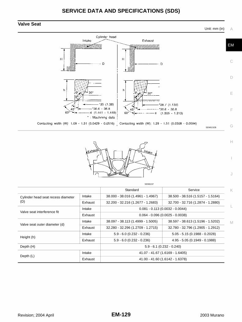
SERVICE DATA AND SPECIFICATIONS (SDS)
EM-129
C
D
E
F
G
H
I
J
K
L
M
A
EM
Revision; 2004 April 2003 Murano
Valve SeatUnit: mm (in)
Standard Service
Cylinder head seat recess diameter (D)
Intake 38.000 - 38.016 (1.4961 - 1.4967) 38.500 - 38.516 (1.5157 - 1.5164)
Exhaust 32.200 - 32.216 (1.2677 - 1.2683) 32.700 - 32.716 (1.2874 - 1.2880)
Valve seat interference fitIntake 0.081 - 0.113 (0.0032 - 0.0044)
Exhaust 0.064 - 0.096 (0.0025 - 0.0038)
Valve seat outer diameter (d)Intake 38.097 - 38.113 (1.4999 - 1.5005) 38.597 - 38.613 (1.5196 - 1.5202)
Exhaust 32.280 - 32.296 (1.2709 - 1.2715) 32.780 - 32.796 (1.2905 - 1.2912)
Height (h)Intake 5.9 - 6.0 (0.232 - 0.236) 5.05 - 5.15 (0.1988 - 0.2028)
Exhaust 5.9 - 6.0 (0.232 - 0.236) 4.95 - 5.05 (0.1949 - 0.1988)
Depth (H) 5.9 - 6.1 (0.232 - 0.240)
Depth (L)Intake 41.07 - 41.67 (1.6169 - 1.6405)
Exhaust 41.00 - 41.60 (1.6142 - 1.6378)
SEM021EB
SEM621F

EM-130
SERVICE DATA AND SPECIFICATIONS (SDS)
Revision; 2004 April 2003 Murano
CAMSHAFT AND CAMSHAFT BEARINGUnit: mm (in)
*: Total indicator reading
CYLINDER BLOCKUnit: mm (in)
Standard Limit
Camshaft journal to bearing clearance
No. 10.045 - 0.086 (0.0018 - 0.0034)
No. 2, 3, 40.035 - 0.076 (0.0014 - 0.0030)
—
Inner diameter of camshaft bearing
No. 126.000 - 26.021 (1.0236 - 1.0244)
No. 2, 3, 423.500 - 23.521 (0.9252 - 0.9260)
—
Outer diameter of camshaft journal
No. 125.935 - 25.955 (1.0211 - 1.0218)
No. 2, 3, 423.445 - 23.465 (0.9230 - 0.9238)
—
Camshaft end play 0.115 - 0.188 (0.0045 - 0.0074) 0.24 (0.0094)
Cam height “A” Intake and exhaust 44.865 - 45.055 (1.7663 - 1.7738) —
Camshaft runout [TIR*] Less than 0.05 (0.0020) —
Camshaft sprocket runout [TIR*] — 0.15 (0.0059)
SEM671
Surface flatness Limit 0.10 (0.0039)
Cylinder bore Inner diameterStandard
Grade No. 1 95.500 - 95.510 (3.7598 - 3.7602)
Grade No. 2 95.510 - 95.520 (3.7602 - 3.7606)
Grade No. 3 95.520 - 95.530 (3.7606 - 3.7610)
Wear limit 0.20 (0.0079)
Out-of-round (Difference between X and Y) Less than 0.015 (0.0006)
Taper (Difference between A and C) Less than 0.010 (0.0004)
PBIC0923E

SERVICE DATA AND SPECIFICATIONS (SDS)
EM-131
C
D
E
F
G
H
I
J
K
L
M
A
EM
Revision; 2004 April 2003 Murano
PISTON, PISTON RING AND PISTON PINAvailable Piston
Unit: mm (in)
Main journal inner diameter grade(Without bearing)
Grade No. AGrade No. BGrade No. CGrade No. DGrade No. EGrade No. FGrade No. GGrade No. HGrade No. JGrade No. KGrade No. LGrade No. MGrade No. NGrade No. PGrade No. RGrade No. SGrade No. TGrade No. UGrade No. VGrade No. WGrade No. XGrade No. YGrade No. 4Grade No. 7
63.993 - 63.994 (2.5194 - 2.5194)63.994 - 63.995 (2.5194 - 2.5195)63.995 - 63.996 (2.5195 - 2.5195)63.996 - 63.997 (2.5195 - 2.5196)63.997 - 63.998 (2.5196 - 2.5196)63.998 - 63.999 (2.5196 - 2.5196)63.999 - 64.000 (2.5196 - 2.5197)64.000 - 64.001 (2.5197 - 2.5197)64.001 - 64.002 (2.5197 - 2.5198)64.002 - 64.003 (2.5198 - 2.5198)64.003 - 64.004 (2.5198 - 2.5198)64.004 - 64.005 (2.5198 - 2.5199)64.005 - 64.006 (2.5199 - 2.5199)64.006 - 64.007 (2.5199 - 2.5200)64.007 - 64.008 (2.5200 - 2.5200)64.008 - 64.009 (2.5200 - 2.5200)64.009 - 64.010 (2.5200 - 2.5201)64.010 - 64.011 (2.5201 - 2.5201)64.011 - 64.012 (2.5201 - 2.5202)64.012 - 64.013 (2.5202 - 2.5202)64.013 - 64.014 (2.5202 - 2.5202)64.014 - 64.015 (2.5202 - 2.5203)64.015 - 64.016 (2.5203 - 2.5203)64.016 - 64.017 (2.5203 - 2.5203)
Difference in inner diameter between cylinders
Standard Less than 0.03 (0.0012)
Piston skirt diameter “A” Standard
Grade No. 1 95.480 - 95.490 (3.7590 - 3.7594)
Grade No. 2 95.490 - 95.500 (3.7594 - 3.7598)
Grade No. 3 95.500 - 95.510 (3.7598 - 3.7602)
0.20 (0.0079) oversize (Service) 95.680 - 95.710 (3.7669 - 3.7681)
“a” dimension 41.0 (1.614)
Piston pin hole diameterGrade No. 0 21.993 - 21.999 (0.8659 - 0.8661)
Grade No. 1 21.999 - 22.005 (0.8661 - 0.8663)
Piston clearance to cylinder blockStandard 0.010 - 0.030 (0.0004 - 0.0012)
Limit 0.08 (0.0031)
SEM882E

EM-132
SERVICE DATA AND SPECIFICATIONS (SDS)
Revision; 2004 April 2003 Murano
Piston RingUnit: mm (in)
Piston PinUnit: mm (in)
CONNECTING RODUnit: mm (in)
*: After installing in connecting rod
Standard Limit
Side clearance
Top 0.045 - 0.080 (0.0018 - 0.0031) 0.11 (0.0043)
2nd 0.030 - 0.070 (0.0012 - 0.0028) 0.1 (0.004)
Oil ring 0.065 - 0.135 (0.0026 - 0.0053) —
End gap
Top 0.23 - 0.33 (0.0091 - 0.0130) 0.54 (0.0213)
2nd 0.33 - 0.48 (0.0130 - 0.0189) 0.80 (0.0315)
Oil (rail ring) 0.20 - 0.50 (0.0079 - 0.0197) 0.95 (0.0374)
Piston pin outer diameterGrade No. 0 21.989 - 21.995 (0.8657 - 0.8659)
Grade No. 1 21.995 - 22.001 (0.8659 - 0.8662)
Interference fit of piston pin to piston 0.002 - 0.006 (0.0001 - 0.0002)
Piston pin to connecting rod bushing oil clearance
Standard 0.005 - 0.017 (0.0002 - 0.0007)
Limit 0.030 (0.0012)
Center distance 144.15 - 144.25 (5.6751 - 5.6791)
Bend [per 100 (3.94)] Limit 0.15 (0.0059)
Torsion [per 100 (3.94)] Limit 0.30 (0.0118)
Connecting rod small end inner diameter 23.980 - 24.000 (0.9441 - 0.9449)
Piston pin bushing inner diame-ter*
Grade No. 0 22.000 - 22.006 (0.8661 - 0.8664)
Grade No. 1 22.006 - 22.012 (0.8664 - 0.8666)
Connecting rod big end inner diameter 55.000 - 55.013 (2.1654 - 2.1659)
Side clearanceStandard 0.20 - 0.35 (0.0079 - 0.0138)
Limit 0.40 (0.0157)
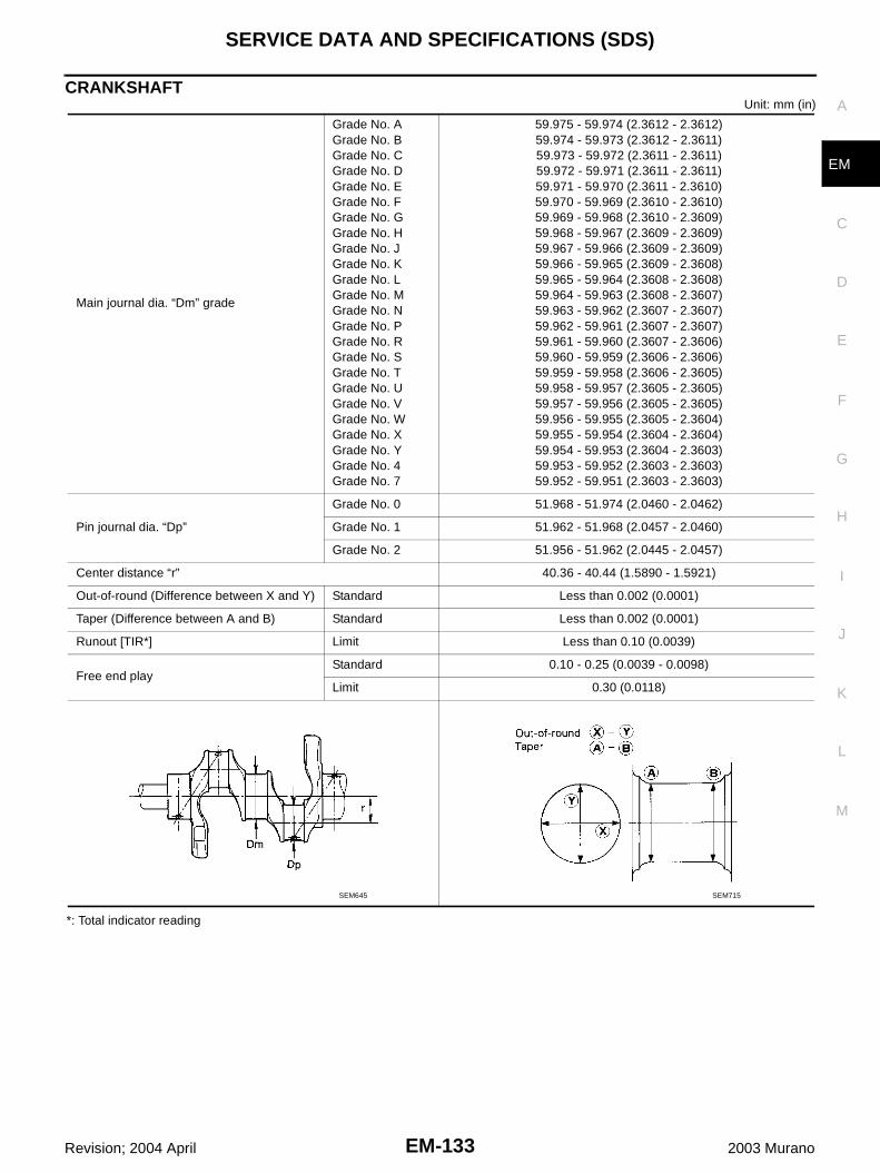
SERVICE DATA AND SPECIFICATIONS (SDS)
EM-133
C
D
E
F
G
H
I
J
K
L
M
A
EM
Revision; 2004 April 2003 Murano
CRANKSHAFTUnit: mm (in)
*: Total indicator reading
Main journal dia. “Dm” grade
Grade No. AGrade No. BGrade No. CGrade No. DGrade No. EGrade No. FGrade No. GGrade No. HGrade No. JGrade No. KGrade No. LGrade No. MGrade No. NGrade No. PGrade No. RGrade No. SGrade No. TGrade No. UGrade No. VGrade No. WGrade No. XGrade No. YGrade No. 4Grade No. 7
59.975 - 59.974 (2.3612 - 2.3612)59.974 - 59.973 (2.3612 - 2.3611)59.973 - 59.972 (2.3611 - 2.3611)59.972 - 59.971 (2.3611 - 2.3611)59.971 - 59.970 (2.3611 - 2.3610)59.970 - 59.969 (2.3610 - 2.3610)59.969 - 59.968 (2.3610 - 2.3609)59.968 - 59.967 (2.3609 - 2.3609)59.967 - 59.966 (2.3609 - 2.3609)59.966 - 59.965 (2.3609 - 2.3608)59.965 - 59.964 (2.3608 - 2.3608)59.964 - 59.963 (2.3608 - 2.3607)59.963 - 59.962 (2.3607 - 2.3607)59.962 - 59.961 (2.3607 - 2.3607)59.961 - 59.960 (2.3607 - 2.3606)59.960 - 59.959 (2.3606 - 2.3606)59.959 - 59.958 (2.3606 - 2.3605)59.958 - 59.957 (2.3605 - 2.3605)59.957 - 59.956 (2.3605 - 2.3605)59.956 - 59.955 (2.3605 - 2.3604)59.955 - 59.954 (2.3604 - 2.3604)59.954 - 59.953 (2.3604 - 2.3603)59.953 - 59.952 (2.3603 - 2.3603)59.952 - 59.951 (2.3603 - 2.3603)
Pin journal dia. “Dp”
Grade No. 0 51.968 - 51.974 (2.0460 - 2.0462)
Grade No. 1 51.962 - 51.968 (2.0457 - 2.0460)
Grade No. 2 51.956 - 51.962 (2.0445 - 2.0457)
Center distance “r” 40.36 - 40.44 (1.5890 - 1.5921)
Out-of-round (Difference between X and Y) Standard Less than 0.002 (0.0001)
Taper (Difference between A and B) Standard Less than 0.002 (0.0001)
Runout [TIR*] Limit Less than 0.10 (0.0039)
Free end playStandard 0.10 - 0.25 (0.0039 - 0.0098)
Limit 0.30 (0.0118)
SEM645 SEM715

EM-134
SERVICE DATA AND SPECIFICATIONS (SDS)
Revision; 2004 April 2003 Murano
AVAILABLE MAIN BEARING
UndersizeUnit: mm (in)
CONNECTING ROD BEARING
Grade number Thickness “T” mm (in) Width “W” mm (in)Identification color
(UPR/LWR)Remarks
0 2.000 - 2.003 (0.0787 - 0.0789)
19.9 - 20.1(0.783 - 0.791)
Black
Grade is the same for upper and lower bear-ings.
1 2.003 - 2.006 (0.0789 - 0.0790) Brown
2 2.006 - 2.009 (0.0790 - 0.0791) Green
3 2.009 - 2.012 (0.0791 - 0.0792) Yellow
4 2.012 - 2.015 (0.0792 - 0.0793) Blue
5 2.015 - 2.018 (0.0793 - 0.0794) Pink
6 2.018 - 2.021 (0.0794 - 0.0796) Purple
7 2.021 - 2.024 (0.0796 - 0.0797) White
01UPP 2.003 - 2.006 (0.0789 - 0.0790)
Brown/Black
Grade is different for upper and lower bear-ings.
LWR 2.000 - 2.003 (0.0787 - 0.0789)
12UPR 2.006 - 2.009 (0.0790 - 0.0791)
Green/BrownLWR 2.003 - 2.006 (0.0789 - 0.0790)
23UPR 2.009 - 2.012 (0.0791 - 0.0792)
Yellow/GreenLWR 2.006 - 2.009 (0.0790 - 0.0791)
34UPR 2.012 - 2.015 (0.0792 - 0.0793)
Blue/YellowLWR 2.009 - 2.012 (0.0791 - 0.0792)
45UPR 2.015 - 2.018 (0.0793 - 0.0794)
Pink/BlueLWR 2.012 - 2.015 (0.0792 - 0.0793)
56UPR 2.018 - 2.021 (0.0794 - 0.0796)
Purple/PinkLWR 2.015 - 2.018 (0.0793 - 0.0794)
67UPR 2.021 - 2.024 (0.0796 - 0.0797)
White/PurpleLWR 2.018 - 2.021 (0.0794 - 0.0796)
SEM175F
Thickness Main journal diameter “Dm”
0.25 (0.0098) 2.132 - 2.140 (0.0839 - 0.0843)Grind so that bearing clearance is the specified value.
Grade number Thickness “T” mm (in) Identification color (mark)
0 1.500 - 1.503 (0.0591 - 0.0592) Black
1 1.503 - 1.506 (0.0592 - 0.0593) Brown
2 1.506 - 1.509 (0.0593 - 0.0594) Green

SERVICE DATA AND SPECIFICATIONS (SDS)
EM-135
C
D
E
F
G
H
I
J
K
L
M
A
EM
Revision; 2004 April 2003 Murano
UndersizeUnit: mm (in)
BEARING CLEARANCEUnit: mm (in)
*: Actual clearance
Tightening Torque ABS0033O
*1: Parts to be tightened in particular orders.1)-: Order of tightening when tightening two or more times separately. Unit: N·m (kg-m, ft-lb) Unit: N·m (kg-m, in-lb)*2
Thickness Crank pin journal diameter “Dp”
0.25 (0.0098) 1.626 - 1.634 (0.0640 - 0.0643)Grind so that bearing clearance is the specified value.
Connecting rod bearing clear-ance
Standard 0.034 - 0.059 (0.0013 - 0.0023)*
Limit 0.070 (0.0028)
Main bearing clearanceStandard 0.035 - 0.045 (0.0014 - 0.0018)*
Limit 0.065 (0.0026)
Mass air flow sensor 5.1 - 6.37 (0.52 - 0.64, 46 - 56)*2
Engine cover 5.00 - 6.47 (0.51 - 0.65, 45 - 57)*2
*1 Intake manifold collector (upper) 17.6 - 21.6 (1.8 - 2.2, 13 - 15)
*1 Intake manifold collector (lower) 17.6 - 21.6 (1.8 - 2.2, 13 - 15)
*1 Electric throttle control actuator 7.2 - 9.6 (0.74 - 0.97, 64 - 84)*2
EVAP canister purge volume control solenoid valve 9.81 - 12.7 (1.0 - 1.2, 87 - 112)*2
*1 Intake manifold 1) 4.9 - 9.8 (0.50 - 1.0, 4 - 7)
2) 26.5 - 31.4 (2.7 - 3.2, 20 - 23)
Exhaust manifold cover 5.1 - 6.5 (0.52 - 0.66, 46 - 57)*2
*1 Exhaust manifold 28.3 - 33.3 (2.9 - 3.3, 21 - 24)
Heated oxygen sensor 1 40 - 50 (4.1 - 5.1, 30 - 36)
Heated oxygen sensor 2 40 - 50 (4.1 - 5.1, 30 - 36)
*1 Oil pan (lower) 9.22 - 10.6 (0.94 - 10.9, 82 - 94)*2
*1 Oil pan (upper) 15.7 - 18.6 (1.6 - 1.9, 12 - 14)
Oil strainer 19.6 - 22.5 (2.0 - 2.2, 15 - 16)
Oil pan drain plug 29.4 - 39.2 (3.0 - 4.0, 22 - 29)
Rear plate cover 6.37 - 7.45 (0.65 - 0.75, 57 - 65)*2
Crankshaft position sensor (POS) 8.4 - 10.8 (0.86 - 1.1, 74.6 - 95.5)*2
Ignition coil 6.37 - 7.54 (0.65 - 0.76, 57 - 66)*2
Spark plug 19.6 - 29.4 (2.0 - 2.9, 15 - 21)
Fuel damper 8.3 - 11.3 (0.85 - 1.2, 73 - 100)*2
Fuel feed hose (with damper) 9.0 - 13.0 (0.92 - 1.3, 80 - 115)*2
*1 Fuel tube 1) 9.3 - 10.8 (0.95 - 1.1, 6.9 - 7.9)
2) 20.6 - 26.5 (2.1 - 2.7, 16 - 19)
*1 Rocker cover 1) 0.96 - 2.96 (0.10 - 0.30, 9 - 26)*2
2) 7.33 - 9.33 (0.75 - 0.95, 65 - 82)*2
PCV valve 1.96 - 2.94 (0.20 - 0.29, 18 - 26)*2
*1 Intake valve timing control cover 9.81 - 12.7 (1.0 - 1.3, 87 - 112)*2

EM-136
SERVICE DATA AND SPECIFICATIONS (SDS)
Revision; 2004 April 2003 Murano
Camshaft sprocket (INT) 98 - 108 (10 - 11, 73 - 79)
Camshaft sprocket (EXH) 118 - 128 (12.0 - 13.1, 87 - 94)
Timing chain tensioner (primary) 6.9 - 9.3 (0.70 - 0.95, 61 - 82)*2
Timing chain tensioner (secondary) 7.0 - 10.0 (0.71 - 1.02, 62 - 88)*2
Internal chain guide 6.9 - 9.3 (0.70 - 0.95, 61 - 82)*2
Tension guide 19.6 - 23.5 (2.0 - 2.3, 15 - 17)
Slack guide 12.7 - 18.6 (1.3 - 1.8, 10 - 13)
Crankshaft pulley 1) 39.2 - 49.0 (4.0 - 5.0, 29 - 36)
2) 60° - 65° (angle tightening)
Chain tensioner cover 9.8 - 12.8 (1.0 - 1.3, 87 - 112)*2
Water pump cover 9.8 - 12.8 (1.0 - 1.3, 87 - 112)*2
*1 Front timing chain case M6 bolt 11.7 - 13.7 (1.2 - 1.4, 9 - 10)
M8 bolt 25.5 - 31.3 (2.6 - 3.2, 19 - 23)
*1 Rear timing chain case 11.7 - 13.7 (1.2 - 1.4, 9 - 10)
*1 Camshaft bracket 1) 1.96 (0.2, 17)*2
2) 5.88 (0.6, 52)*2
(No.1 to 6) 3) 9.02 - 11.8 (0.92 - 1.20, 80 - 104)*2
(No.7 to 10) 3) 8.3 - 10.3 (0.85 - 1.0, 74 - 91)*2
Camshaft position sensor (PHASE) 8.4 - 10.8 (0.86 - 1.1, 75 - 95)*2
Intake valve timing control solenoid valve 9.8 - 12.7 (1.0 - 1.3, 87 - 112)*2
*1 Cylinder head 1) 98.1 (10.0, 72)
2) 0 (0.0, 0)
3) 34.3 - 44.1 (3.5 - 4.4, 26 - 32)
4) 90° - 95° (angle tightening)
5) 90° - 95° (angle tightening)
*1 Main bearing cap 1) 32.3 - 38.3 (3.3 - 3.9, 24 - 28)
2) 90° - 95° (angle tightening)
Connecting rod 1) 18.6 - 20.6 (1.9 - 2.1, 14 - 15)
2) 90° - 95° (angle tightening)
Oil jet 23.6 - 30.4 (2.4 - 3.1, 18 - 22)
Knock sensor 20.6 - 26.5 (2.1 - 2.7, 16 - 19)
Drive plate 83 - 93 (8.5 - 9.5, 61 - 69)
Rear oil seal retainer 8.14 - 9.36 (0.83 - 0.95, 72 - 82)*2