Engine Installation and Operation Manual...TEO-540-C1A Engine Installation and Operation Manual...
118
© 2019 Avco Corporation. All Rights Reserved Engine Installation and Operation Manual TEO-540-C1A Engine April 2019 Part No. IOM-TEO-540-C1A Rev 1
Transcript of Engine Installation and Operation Manual...TEO-540-C1A Engine Installation and Operation Manual...

© 2019 Avco Corporation. All Rights Reserved
Engine Installation and Operation Manual
TEO-540-C1A Engine
April 2019
Part No. IOM-TEO-540-C1A Rev 1

TEO-540-C1A Engine Installation and Operation Manual Lycoming Part Number: IOM-TEO-540-C1A Rev 1
Contact Us:
Mailing Address:
Lycoming Engines 652 Oliver Street Williamsport, PA 17701 USA
Phone:
Factory U.S. and Canada Toll Free:
Direct:
+1 (800) 258-3279
+1 (570) 323-6181
Technical Support Hotline
• +1 (877) 839-7878 (Toll Free)
• +1 (570) 327-7222
• Email [email protected]
Lycoming’s regular business hours are Monday through Friday from 8:00AM through 5:00PM Eastern Time (-5 GMT).
Visit us Online: www.lycoming.com
NOTE:
Lycoming recommends that owners of this manual sign up for email notification on the Technical Publications page of our website https://www.lycoming.com/contact/knowledge-base/publications. By submitting your email address, you will receive notification whenever Lycoming publishes a new or revised technical publication, including any revisions to this Engine Installation and Operation Manual.

© 2019 Avco Corporation. All Rights Reserved Record of Revisions April 2019 Page i
TEO-540-C1A Engine Installation and Operation Manual
RECORD OF REVISIONS
Revision
Revision
Date Revision Description
Original
Original Release of Installation and Operation Manual -
Part No. IOM-TEO-540-C1A
Rev. 1 April 2019 System Description
• EECS Architecture
o Revised the description of the ECU and Power Box connection to
the engine due to change in wiring harness configuration
o Revised Figure 4
• Revised Figure 5 in the Field Service Tool (FST) section due to
change to wiring harness configuration
• Revised the description in the Wiring Harness section due to change
in the wiring harness configuration
• Revised the abbreviation for the Knock Sensor in Table 2
Theory of Operation
• Added new section for Generated Power Calculation
Engine Reception and Lift
• Revised Step 1,A to include additional shipping methods
Engine Installation
• Revised Step 3 due to change in the wiring harness configuration
• Revised Figure 1 due to change in the wiring harness configuration
• Revised Step 5 due to change in the wiring harness configuration
Engine Initiation
• Revised the CAUTION after Step 12 in “Step 3. Engine Start”
• Revised the rpm range and CHT temperature range for the PFT
criteria in “Step 6. Complete the Pre-Flight Test”
• Revised the maximum rpm identified in Step 5,D in “Step 6.
Complete the Pre-Flight Test”
• Revised the maximum CHT identified in Step 5,D in “Step 6.
Complete the Pre-Flight Test”
Engine Operation
• Step 2. Engine Start
o Revised the CAUTION after Step 11
o Reversed the order of Steps 11 and 12
• Step 4. Pre-Flight Test
o Revised the rpm range and CHT temperature range for the PFT
criteria
o Revised the maximum rpm identified in Step 5,D
o Revised the maximum CHT identified in Step 5,D

Record of Revisions © 2019 Avco Corporation. All Rights Reserved Page ii April 2019
TEO-540-C1A Engine Installation and Operation Manual
RECORD OF REVISIONS (CONT.)
Revision
Revision
Date Revision Description
Rev. 1 April 2019 Abbreviations and Acronyms
• Added listings for psia, psid, and psig
Appendix A
• Table A-1
o Changed Spark Plug Advance from 20º BTC to 15º BTC
o Changed the critical altitude for Maximum Rated Continuous HP
from 12,000 feet to 10,000 feet
• Table A-2
o Changed the Maximum Heat Rejection to Oil from 1750
Btu/minute to 2160 Btu/minute
o Changed Minimum Fuel Rail Pressure from 33 psid to 43 psid
o Revised all Minimum Fuel Consumption values
o Changed Maximum Manifold Pressure from 52 in. hg. To 57.9 in.
hg.
o Changed Critical Altitude (at standard day conditions) from
12,000feet to 10,000 feet
• Added new accessories Fuel Pump and Compressor to Table A-3
• Revised Figures A-1, A-2, A-3, A-4, A-5, and A-6

© 2019 Avco Corporation. All Rights Reserved Service Document List April 2019 Page iii
TEO-540-C1A Engine Installation and Operation Manual
SERVICE DOCUMENT LIST
NOTICE: The following is a list of service documents referenced in or incorporated into the
information in this manual. Always refer to the latest revision of any service document
for changes or additional information. Supplements to a service document contain
information relevant to the service document but not yet added to the service document.
The latest revision of all service documents in this list can be downloaded from our
website https://www.lycoming.com/contact/knowledge-base/publications.
To narrow the search parameters and limit the number of returns, enter only the
numerical portion of the service document number in the Search box on the website.
Number Incorporation
Date Subject
S.B. 369 11/18 Engine Inspection after Overspeed
S.B. 480 11/18 I. Oil and Filter Change and Screen Cleaning
II. Oil Filter Screen Content Inspection
S.B. 533 11/18 Recommended Action for Sudden Engine Stoppage,
Propeller/Rotor Strike or Loss of Propeller/Rotor Blade
or Tip
S.I. 1011 11/18 Table of Current Tappet Bodies, Plunger Assemblies and
Hydraulic Lifter Assemblies
S.I. 1014 11/18 Lubricating Oil Recommendations
S.I. 1070 11/18 Specified Fuels
S.I. 1241 11/18 Pre-oil the Engine Prior to Initial Start
S.I. 1304 11/18 Engine Nameplate Replacement
S.I. 1409 11/18 Lycoming Engines P/N LW-16702, Oil Additive
S.I. 1427 11/18 Lycoming Reciprocating Engine Run-In and Oil
Consumption
S.I. 1472 11/18 Removal of Preservative Oil from Engine
S.I. 1481 11/18 Factory Engine Preservation
S.I. 1505 11/18 Cold Weather Starting
S.I. 1528 11/18 Aircraft Engine Starter Recommendations
S.I. 1530 11/18 Engine Inspection in a Particulate Laden Environment
(Volcanic Ash, Sand, Dust, Airborne Debris)
S.I. 1566 11/18 Lycoming Engines Approves the Use of Safety Cable
S.I. 1573 11/18 Lycoming TEO-540 Engine Series Engine Control Unit
(ECU) Assembly Cross-References
L 114 11/18 Reciprocating Engine and Accessory Maintenance
Publications
L180 11/18 Engine Preservation for Active and Stored Aircraft
L193 11/18 Engine Firing Order

Service Document List © 2019 Avco Corporation. All Rights Reserved Page iv April 2019
TEO-540-C1A Engine Installation and Operation Manual
This page intentionally left blank.

© 2019 Avco Corporation. All Rights Reserved Table of Contents April 2019 Page v
TEO-540-C1A Engine Installation and Operation Manual
TABLE OF CONTENTS
Section Page
Frontal __________________________________________________________________________
Record of Revisions .............................................................................................................................. i
Service Document List ....................................................................................................................... iii
Table of Contents ................................................................................................................................ v
List of Figures ..................................................................................................................................... ix
List of Tables ...................................................................................................................................... xi
Abbreviations and Acronyms ......................................................................................................... xiii
Introduction ..................................................................................................................................... xvii
System Description ________________________________________________________________
— System Description ................................................................................................................... 1
— Electronic Engine Control System (EECS) .............................................................................. 2
— EECS Architecture .................................................................................................................... 3
— Field Service Tool (FST) .......................................................................................................... 4
— EECS Operation ........................................................................................................................ 5
— Electrical Interface .................................................................................................................... 6
— Wiring Harnesses ...................................................................................................................... 6
— Sensors ...................................................................................................................................... 7
— Cylinders ................................................................................................................................... 8
— Crankcase .................................................................................................................................. 8
— Propeller Drive .......................................................................................................................... 9
— Fuel System ............................................................................................................................... 9
— Electronic Ignition System ...................................................................................................... 10
— Air Induction System .............................................................................................................. 11
— Turbocharger ........................................................................................................................... 11
— Accessory Housing/Accessory Drive Pads ............................................................................. 11
— Lubrication System ................................................................................................................. 11
— Engine Mounting..................................................................................................................... 13
— Cylinder Number Designations ............................................................................................... 13

Table of Contents © 2019 Avco Corporation. All Rights Reserved Page vi April 2019
TEO-540-C1A Engine Installation and Operation Manual
Section Page
Theory of Operation ______________________________________________________________
— EECS Operation ...................................................................................................................... 15
— Engine Control Sequence ........................................................................................................ 16
— Engine Synchronization .......................................................................................................... 16
— Fuel Control ............................................................................................................................ 16
— Ignition Control ....................................................................................................................... 16
— Load Sensing ........................................................................................................................... 16
— Inoperative Cylinder Detection ............................................................................................... 16
— Cylinder Head Temperature Control ....................................................................................... 17
— Turbocharger Turbine Inlet Temperature Control .................................................................. 17
— Turbocharger Control .............................................................................................................. 17
— Engine Overhaul vs. Engine Rebuild ...................................................................................... 17
— Timekeeping............................................................................................................................ 17
Pilot Controls ____________________________________________________________________
— Pilot Controls .......................................................................................................................... 19
— Warning Indication Annunciators ........................................................................................... 20
Engine Reception and Lift __________________________________________________________
— Uncrate Procedure for a New, Rebuilt, or Overhauled Engine ............................................... 21
— Acceptance Check ................................................................................................................... 21
— Engine Preservative Oil Removal ........................................................................................... 22
— Lift the Engine ........................................................................................................................ 22
Requirements for Engine Installation ________________________________________________
— Overview ................................................................................................................................. 25
— Step-1. Prepare the Engine ...................................................................................................... 25
— Step-2. Supply Interface Items ................................................................................................ 31
— Step-3. Remove Components .................................................................................................. 32
— Step-4. Install Engine Mounting Brackets .............................................................................. 32

© 2019 Avco Corporation. All Rights Reserved Table of Contents April 2019 Page vii
TEO-540-C1A Engine Installation and Operation Manual
Section Page
Engine Installation ________________________________________________________________
— Engine Installation Overview .................................................................................................. 33
— Step-1. Install the ECU ........................................................................................................... 34
— Step-2. Install the Power Box ................................................................................................. 34
— Step-3. Install the Engine on Mounts ...................................................................................... 34
— Step-4. Connect the Wiring Harnesses ................................................................................... 35
— Step 5. Connect the Power Control Linkage ........................................................................... 36
— Step-6. Install External Accessories ........................................................................................ 37
— Step-7. Install the Alternator ................................................................................................... 37
— Step-8. Install the Propeller ..................................................................................................... 37
— Step-9. Connect the Fuel Hoses .............................................................................................. 37
— Step-10. Connect Oil Hoses .................................................................................................... 38
— Step-11. Attach Ground Straps ............................................................................................... 38
— Step-12. Install Components That Had Been Removed Before Engine Installation
and Any Additional Ship Loose Components.......................................................... 39
— Step-13. Make Remaining Engine Connections ..................................................................... 39
— Step-14. Install Baffling .......................................................................................................... 39
— Step-15. Add Oil ..................................................................................................................... 39
— Step-16. Engine Pre-Oil Procedure ......................................................................................... 40
— Step-17. Add Fuel ................................................................................................................... 41
— Step-18. Make RPM Measurements ....................................................................................... 41
— Step-19. Final Installation Inspection ..................................................................................... 41
— Step-20. Close Engine Compartment ...................................................................................... 41
— Engine Installation Checklist .................................................................................................. 42
Field Run-In _____________________________________________________________________
— Field Run-In Procedure ........................................................................................................... 43
Engine Initiation __________________________________________________________________
— Engine Initiation ...................................................................................................................... 47
— Warranty Requirement ............................................................................................................ 47
— Step 1. Pre-Flight Inspection for Engine Initiation ................................................................. 47
— Step 2. Pre-Start Inspection ..................................................................................................... 50
— Step 3. Engine Start ................................................................................................................. 50
— Step 4. Operational Test .......................................................................................................... 51

Table of Contents © 2019 Avco Corporation. All Rights Reserved Page viii April 2019
TEO-540-C1A Engine Installation and Operation Manual
Section Page
Engine Initiation (Cont.) ___________________________________________________________
— Step 5. Engine Run-Up ........................................................................................................... 53
— Step 6. Complete the Pre-Flight Test ...................................................................................... 54
— Step 7. Engine Stop ................................................................................................................. 57
— Step 8. Break-In/Flight Test/50-Hour Operation .................................................................... 57
— Step 9. Required Inspections During Break-In (50-Hour Operation) ..................................... 59
Engine Operation _________________________________________________________________
— Step 1. Pre-Flight Test ............................................................................................................ 61
— Step 2. Engine Start ................................................................................................................. 61
— Step 3. Engine Run-Up ........................................................................................................... 63
— Step 4. Pre-Flight Test ............................................................................................................ 63
— Step 5. Engine Operation ........................................................................................................ 67
— Step 6. Engine Stop ................................................................................................................. 68
Engine Conditions ________________________________________________________________
— Fault Isolation – Use of Field Service Tool ............................................................................ 69
— Faults ....................................................................................................................................... 69
— Required Action for Engine Conditions .................................................................................. 69
—Apply Heat to a Cold Engine .............................................................................................. 73
—Cold Weather Engine Start ................................................................................................ .74
—Engine Operation in Hot Weather ....................................................................................... 74
—Volcanic Ash ....................................................................................................................... 75
—Overspeed............................................................................................................................ 75
—Low Oil Pressure During Flight .......................................................................................... 76
Engine Preservation and Storage ____________________________________________________
— Engine Corrosion and Prevention ........................................................................................... 77
— Engine Preservation Guidelines - 31 to 60 Days .................................................................... 78
— Extended Engine Preservation for 61 Days or More .............................................................. 80
— Fuel Injector Preservation ....................................................................................................... 80
Appendix ________________________________________________________________________
— Appendix A Engine Specifications and Operating Limits ...................................................... 81
— Appendix B Operating Limitations ......................................................................................... 91
— Appendix C Safety .................................................................................................................. 93
— Appendix D Wiring Diagrams ................................................................................................ 95

© 2019 Avco Corporation. All Rights Reserved List of Figures April 2019 Page ix
TEO-540-C1A Engine Installation and Operation Manual
LIST OF FIGURES
Fig. No. Figure Title Page
System Description
1 TEO-540-C1A Engine 1
2 EECS Integrated Components 2
3 EECS Primary Components 3
4 Wiring Harness 3
5 EECS Overview 4
6 Engine Control 5
7 TEO-540-C1A Engine Fuel System 9
8 Electronic Ignition System 10
9 Oil System Schematic 12
10 Cylinder Number Designation 13
Pilot Controls and Annunciators
1 EECS Cockpit Controls and Indicators 19
Engine Reception and Lift
1 Example of Engine Box/Crate 21
2 Engine Data Plate 21
3 Engine Lift 22
Requirements for Engine Installation
1 Oil Sump Drain Plugs and Oil Suction Screen 26
2 Plug in the Induction System 27
3 Fuel Drain Valve Adapter Assembly Installed in the Induction System 27
4 Engine Mounts 32
Engine Installation
1 Wiring Harness Installed on TEO-540-C1A Engine 35
2 Red Colored Band on the Receptacle 36
3 Correctly Installed Threaded Plug 36
Appendix A
A-1 Cooling Air Requirements 85
A-2 Propeller Governor Oil Transfer Leakage Rate 86
A-3 2500 RPM Sea Level and Altitude Performance 87
A-4 2400 RPM Sea Level and Altitude Performance 88
A-5 2200 RPM Sea Level and Altitude Performance 89
A-6 Fuel Flow versus Percent of Rated Power 90
List of Figures © 2019 Avco Corporation. All Rights Reserved Page x April 2019
TEO-540-C1A Engine Installation and Operation Manual
This page intentionally left blank.

© 2019 Avco Corporation. All Rights Reserved List of Tables April 2019 Page xi
TEO-540-C1A Engine Installation and Operation Manual
LIST OF TABLES
Table
No. Table Title Page
System Description Section
1 Engine Electrical Interface 6
2 Sensors 7
Pilot Controls and Annunciators
1 Pilot Controls 19
2 Indicator Annunciators 20
Requirements for Engine Installation Section
1 Prerequisites for Engine Installation 25
Engine Installation Section
1 Engine Installation Steps and References 33
Engine Initiation
1 Engine Initiation Procedures for All Lycoming Engines 47
Engine Operation
1 Prerequisite Requirements for Engine Operation 61
Engine Conditions
1 Action for Engine Conditions 69
Appendix A - Engine Specifications and Operating Limits
A-1 TEO-540-C1A Engine Specifications 81
A-2 Table of Operating Limits for Engine 82
A-3 Accessory Drives 84
Appendix B - Operating Limitations
B-1 Physical Environmental Limits 91
Appendix C - Safety Criteria
C-1 Safety Alert Messages 93

List of Tables © 2019 Avco Corporation. All Rights Reserved Page xii April 2019
TEO-540-C1A Engine Installation and Operation Manual
This page intentionally left blank.

© 2019 Avco Corporation. All Rights Reserved Abbreviations and Acronyms April 2019 Page xiii
TEO-540-C1A Engine Installation and Operation Manual
ABBREVIATIONS AND ACRONYMS
A
AC Alternating Current
ACU Engine Control Unit
ADL Data Logger
AMP Ampere
B
BHP Brake Horsepower
BIT Built-In Test
BTC Before Top Center
C
C Celsius
CAM Camshaft Speed Sensor
CAN Controller Area Network
CHT Cylinder Head Temperature
CIP-P Primary Compressor Inlet Pressure
CIP-S Secondary Compressor Inlet Pressure
cm Centimeter
CRANK Crankshaft Speed Sensor
D
DC Direct Current
DECK-P-P Primary Induction Air Deck Temperature
DECK-P-S Secondary Induction Air Deck Temperature
DECK-T Induction Air Deck Temperature
DPS Delta Pressure Sensor
E
ECU Engine Control Unit
EECS Electronic Engine Control System
EGT Exhaust Gas Temperature
EOP Engine Oil Pressure
EOT Engine Oil Temperature
ESD Electrostatic Discharge

Abbreviations and Acronyms © 2019 Avco Corporation. All Rights Reserved Page xiv April 2019
TEO-540-C1A Engine Installation and Operation Manual
ABBREVIATIONS AND ACRONYMS (CONT.)
F
F Fahrenheit
FAA Federal Aviation Administration
FAR Federal Aviation (and Space) Regulation
FFL Fault Found
FFPD Fuel Filter Pressure Drop
FOD Foreign Object Debris
FPP Fuel Pump Pressure Sensor
FST Field Service Tool
Ft.-lb. Foot Pound (torque)
FUEL-P Fuel Rail Pressure Sensor
FUEL-T Fuel Temperature Sensor
H
Hg Mercury
HIRF High Intensity Radiated Field
I
ICA Instructions for Continued Airworthiness
ICD Interface Control Document
in. Inch, inches
in.-lb Inch Pound (torque)
In-Hg Inches of Mercury
K
KNOCK Knock Sensor
kPa Kilopascals
L
lb Pound
LL Low Lead (fuel)
M
MAP Manifold Air Pressure
MAT-P Primary Induction Air Manifold Temperature Sensor
MAT-S Secondary Induction Air Manifold Temperature Sensor
mm Millimeter
N
Nm Newton Meters
NPT National Pipe Thread
NTO No Take-Off

© 2019 Avco Corporation. All Rights Reserved Abbreviations and Acronyms April 2019 Page xv
TEO-540-C1A Engine Installation and Operation Manual
ABBREVIATIONS AND ACRONYMS (CONT.)
O
OIL-P Oil Pressure Sensor
OIL-T Oil Temperature Sensor
P
PFT Pre-Flight Test
PMA Permanent Magnet Alternator
P/N Part Number
POH Pilot Operating Handbook
psi Pounds per square inch
psia Pounds per square inch absolute
psid Pounds per square inch absolute differential
psig Pounds per square inch gage
R
RCA Radio Corporation of America
rpm Revolutions per Minute
S
SAE Society of Automotive Engineers (oil viscosity)
SB Service Bulletin
SI Service Instruction
T
TIT Turbine Inlet Temperature Sensor
TLO Time-Limited Operation
TPS Throttle Position Sensor
U
UL Unleaded (gasoline)
V
V Volt, Voltage

Abbreviations and Acronyms © 2019 Avco Corporation. All Rights Reserved Page xvi April 2019
TEO-540-C1A Engine Installation and Operation Manual
This page intentionally left blank.

TEO-540-C1A Engine Installation and Operation Manual
© 2019 Avco Corporation. All Rights Reserved Introduction April 2019 Page xvii
INTRODUCTION
Engine Model Nomenclature
The table below shows the definition of each letter and number for the TEO-540 engine model
nomenclature. Numbers and letters in the suffix (C1A) of the engine model number are configuration
designations associated with the core engine.
Model Number Meaning
T Turbocharged
E Electronic Engine Control System
O Horizontally Opposed
540 Displacement in cubic inches
Scope of this Manual
This manual supplies an engine description and instructions for uncrating procedures, acceptance
check, engine lift procedure, engine preservation and storage, depreservation, engine installation
requirements, engine installation, operation and stop procedures, engine initiation (break-in/flight
test), fuels and oil to be used, and operating specifications for TEO-540-C1A Lycoming aircraft
engines.
NOTICE: The installation instructions in this manual are basic guidelines. When installing the
engine in the airframe, follow the airframe manufacturer’s installation instructions.
For maintenance procedures, such as: oil changes, oil addition, oil filter replacement, routine time-
interval inspections, routine service, spark plug replacement/inspection procedures, cylinder
inspection, fuel system inspection, scheduled servicing procedures, airworthiness limitations, fault
isolation guidelines and procedures to replace components and to disassemble and assemble the
engine, refer to the TEO-540-C1A Engine Maintenance Manual.
For spare parts information, refer to the TEO-540-C1A Illustrated Parts Catalog.
Refer to the latest revision of the Service Table of Limits - SSP-1776, for dimensions, clearances,
measurements, and torque values.
Service Bulletins, Service Instructions, and Service Letters
As advancements in technological applications on this engine continue, Lycoming Engines will
make future revisions to this manual. However, if more timely distribution is necessary, Lycoming
Engines supplies up-to-date Service Bulletins (SBs), Service Instructions (SIs) and Service Letters
(which are abbreviated with a capital “L” followed by the number, example L180). Special
Advisories (SAs) are supplied as necessary.
For additional publication information, look on Lycoming’s website (Lycoming.com) or speak to
Lycoming Engines by telephone: U.S. and Canada toll free: +1(800) 258-3279; or Direct: +1 (570)
323-6181.
Applicable information from Lycoming Engines' Service Bulletins, Service Instructions, and Service
Letters are included in this manual at the time of publication. Any new service information will be
included in the next update of the manual.
Reminder: Unless otherwise specified, Lycoming Engines' service documents (which are dated
after this manual’s release date) that pertain to the engine model in this manual
supersede procedures in this manual.
For reference and future updates, the Service Document List at the front of this manual identifies the
service documents included in this manual.

Introduction © 2019 Avco Corporation. All Rights Reserved Page xviii April 2019
TEO-540-C1A Engine Installation and Operation Manual
List of Publications
Refer to the latest revision of Service Letter No. L114 for a list of Lycoming Engines' publications.
Compliance Requirements
WARNING OPERATE THIS ENGINE IN ACCORDANCE WITH SPECIFICATIONS IN
APPENDIX A OF THIS MANUAL. OPERATION OF THE ENGINE
BEYOND SPECIFIED OPERATING LIMITS CAN CAUSE PERSONAL
INJURY AND/OR DAMAGE TO THE ENGINE.
YOU ALSO MUST COMPLETE THE NECESSARY SERVICE
PROCEDURES IDENTIFIED IN LYCOMING ENGINES' MAINTENANCE
MANUAL FOR THIS ENGINE AS WELL AS ANY APPLICABLE SERVICE
DOCUMENTS. LYCOMING ENGINES' SERVICE DOCUMENTS WRITTEN
AT A LATER DATE OVERRIDE PROCEDURES IN THIS MANUAL.
PROCEDURES IN THE MAINTENANCE MANUALS MUST BE DONE BY
QUALIFIED PERSONNEL WITH THE REQUISITE CERTIFICATIONS.
Warning, Cautions, and Notices
Be sure to read and obey the Warnings, Cautions and Notices in this manual and in service
documents. Although Lycoming Engines cannot know all possible hazards or damages, it does its
best to make a reasonable effort to supply the best guidance and recommended practices for safe
operation of its engines.
The table below defines the four types of safety advisory message used in this manual as per the
American National Standard and ANSI Z535-6-2006.
Safety Advisory Conventions
Advisory Word Definition
DANGER: Indicates a hazardous situation which, if not avoided, will result
in death or serious injury. This signal word is to be limited to the
most extreme situations.
WARNING Indicates a hazardous situation which, if not avoided, could
result in death or serious injury.
CAUTION Indicates a hazardous situation which, if not avoided, could
result in minor or moderate injury. It can also be used without
the safety alert symbol as an alternative to "NOTICE."
NOTICE: The preferred signal word to address practices not related to
personal injury.
NOTICE: In this manual, the word "recommended" refers to "best practices."
Instructions for Continued Airworthiness
The TEO-540-C1A Engine Maintenance Manual, TEO-540-C1A Engine Overhaul Manual, the
latest revision of the Service Table of Limits - SSP-1776, and service documents applicable to this
engine model make up the complete set of Instructions for Continued Airworthiness (ICAs). The
ICAs are prepared by Lycoming Engines and are accepted by the Federal Aviation Administration
(FAA).

© 2019 Avco Corporation. All Rights Reserved Introduction April 2019 Page xix
TEO-540-C1A Engine Installation and Operation Manual
Simplified Technical English
The text in the manual is written in the form of Simplified Technical English in compliance with
FAA requirements and to make translation into other languages easier.
Figures
Figures in this manual are for conceptual illustrative purposes only. Figures always start as Figure 1
in each chapter.
Tables and Checklists
Tables in this manual are used to display detailed information in an organized format. Tables always
start as Table 1 in each chapter. Checklists are used to display a list of tasks to be completed as part
of a specific procedure. Checklists are not numbered because they are used as a reference tool
contained within the procedure.
Copyright
This publication is a copyrighted work. All rights reserved by Lycoming Engines. Content in this
manual cannot be changed or released as a reprint, electronic media output, or web communiqué
without written permission from Lycoming Engines.
Environmental Compliance
Lycoming Engines recommends that engine owners and service personnel be in compliance with all
federal, state, and local environmental regulations when solvents, paint, fuel, oil, chemicals, or other
consumables are used in engine service.
Feedback
To supply comments, suggestions, or corrections to this manual, either email or contact Lycoming
Engines Technical Support at the email or phone number in the front of this manual or use the
Lycoming.com website.
Manual Revisions
Lycoming Engines constantly examines our manuals to provide our customers the most complete
and up-to-date information for operating and maintaining our engines. Revisions to this manual will
be published as necessary.
Patents
The following patents apply to the engine and control systems:
• 7,658,184
• 7,875,989
• 7,827,965
• 8,131,406
• 7,828,509

Introduction © 2019 Avco Corporation. All Rights Reserved Page xx April 2019
TEO-540-C1A Engine Installation and Operation Manual
This page intentionally left blank.

© 2019 Avco Corporation. All Rights Reserved System Description April 2019 Page 1
TEO-540-C1A Engine Installation and Operation Manual
SYSTEM DESCRIPTION
The Lycoming TEO-540-C1A Engine (Figure 1) is a direct-drive six-cylinder, horizontally opposed,
turbocharged, electronically-controlled engine. It has electronic fuel injection, electronic ignition,
and down exhaust. As standard equipment, this engine has an automotive type starter, an alternator,
and two standard AN type accessory drives.
The engine has an Electronic Engine Control System (EECS) which is a microprocessor. The EECS
continuously monitors and automatically adjusts operating conditions such as ignition timing, fuel
injection timing, and fuel mixture. The EECS eliminates the need for magnetos and manual fuel/air
mixture control.
Figure 1
TEO-540-C1A Engine
System Description © 2019 Avco Corporation. All Rights Reserved Page 2 April 2019
TEO-540-C1A Engine Installation and Operation Manual
Electronic Engine Control System (EECS)
The EECS is an electronic, microprocessor controlled system that continuously monitors and adjusts
ignition timing, fuel injection timing, and fuel mixture based on operating conditions. The EECS
eliminates the need for magnetos and manual fuel/air mixture. Figure 2 shows the EECS integrated
controls.
The EECS connects engine hardware with electronic controls to replace mechanical control systems
and enables single lever engine control.
Figure 2
EECS Integrated Controls

© 2019 Avco Corporation. All Rights Reserved System Description April 2019 Page 3
TEO-540-C1A Engine Installation and Operation Manual
EECS Architecture
The EECS architecture consists of:
• Primary components (Figure 3):
o Engine Control Unit (ECU) (also identified as ACU)
- is a dual channel unit which contains system
processors, input signal conditioning, output
actuator drive stages, and aircraft communication
interfaces. The ACU Controller Area Network
(CAN) bus communications linked to a host
personal computer can be used to monitor the
system and upload logged data.
o Power Box - a dual channel unit which supplies
regulated primary and secondary 14V power over to
the EECS. Airframe power at start-up or when
engine speed is below 1000 rpm supplies power to
the power box regulators. When engine rpm is above
1000 rpm, a dedicated Permanent Magnet Alternator
(PMA) (mounted on the engine accessory drive)
supplies power to the power box.
o Data Logger (ADL) - a single channel unit that
records data received from the ACU via the CAN
bus communication.
Figure 3
EECS Primary Components
• Secondary components:
o Engine harness o Sensors o Actuators.
The ECU and Power Box are connected by a wiring harness (Figure 4) to the engine. Two channels
on the ECU communicate with each other through a CAN bus (CAN1). Each channel has input
processing, a microprocessor and output processing which control the engine independently of each
other. Sensors connected to the engine harness send inputs to the ECU to control the engine through
output to the actuators. The actuators also are connected to the ECU by the same wiring harness.
Refer to Figure 5 for a general EECS overview.
Figure 4
Wiring Harness
NOTICE: The ECU software is unique to each engine and is not to be installed on any other
engine unless it has been re-configured.

System Description © 2019 Avco Corporation. All Rights Reserved Page 4 April 2019
TEO-540-C1A Engine Installation and Operation Manual
Field Service Tool (FST)
The Field Service Tool (FST) is diagnostic software that identifies fault codes (Appendix C in the
TEO-540-C1A Engine Maintenance Manual) and engine operation information to be used by
ground-based support personnel to:
• View fault codes from the ECU
• Upload fault codes from the ECU
• Monitor ECU operation
• Upload data from the data logger (if needed)
The EECS collects internal fault log data and external fault log data. Maintenance personnel use this
data for diagnostic and continuous airworthiness.
Access to this tool is through a laptop where the software is installed and through an established link
with the EECS for the engine using the iE2 Service Cable (ST-528) and the iE2 Field Service Tool
CAN Interface (ST-530) connected to an RCA jack on the airframe engine wiring harness.
Figure 5
EECS Overview
© 2019 Avco Corporation. All Rights Reserved System Description April 2019 Page 5
TEO-540-C1A Engine Installation and Operation Manual
EECS Operation
The EECS does not have redundant actuators. It has only one fuel injector per cylinder, one exhaust
bypass valve, and one propeller governor. Both channels (microprocessors) are capable of
controlling the actuators but only one channel within the ECU can control the actuators at a given
time - with the exception of the ignition coils, which are redundant with two per cylinder. Each
channel can control six of the 12 coils, one for each cylinder. The primary and secondary channels
must work simultaneously to control and activate all 12 spark plugs. The channel in control sends
output to the fuel injectors, exhaust bypass valve, propeller governor, and its six ignition coils. The
other channel sends output to its six ignition coils. These outputs control fuel flow, induction
manifold pressure, engine speed, and ignition timing.
The ECU transmits output data through two CAN buses (CAN2 and CAN3) and one RS232 bus
(Figure 6). The CAN2 is used to connect the FST. An RCA female receptacle is required as a
connector for the FST thru CAN2. The FST has a cable with an RCA male jack that mates with this
receptacle.
The CAN3 and RS232 buses transmit engine parameters and EECS operational status information to
the aircraft display. The airframe manufacturer can use either the CAN3 bus or RS232 bus to supply
information necessary for the airframe third party display units.
Figure 6
Engine Control

System Description © 2019 Avco Corporation. All Rights Reserved Page 6 April 2019
TEO-540-C1A Engine Installation and Operation Manual
The Power Box supplies regulated, conditioned 13.8 VDC power through primary and secondary
channels to the ECU, ignition coils, and warning annunciators. Each Power Box channel is identical
and independent of the other and corresponds to the primary and secondary channels of the ECU.
Each Power Box channel can provide sufficient power to operate the EECS through its
corresponding ECU channel if one Power Box channel fails.
Each channel of the Power Box can get power from either the airframe-supplied 28 VDC or the
engine-driven Permanent Magnet Alternator (PMA) which supplies three-phase AC power. The
PMA is driven from the engine’s accessory housing and is the dedicated source of primary power for
the Power Box. The Power Box selects the applicable power source for the EECS either from
airframe power or the PMA. The Power Box can only use power from one source at a time and
cannot get power from both sources simultaneously.
Airframe power only is used under the following conditions:
• During engine start
• When the engine speed is below approximately 1000 rpm
• When the PMA has failed.
Each Power Box Channel has a dedicated ground connected to a common airframe ground.
Electrical Interface
Table 1 identifies elements of the electrical interface for the engine.
Table 1
Engine Electrical Interface
Element Description
EECS electrical input power requirements Must have a supply voltage of between 12 and
28 VDC. The EECS must have airframe electric
power for start-up and as a redundant back-up to
engine power from the EECS-dedicated PMA.
NOTICE: The minimum usable voltage for the
system is 10.5 VDC.
Interface The airframe power is supplied to the EECS
through a four-pin plug on the wiring harness.
Wiring Harnesses
The wiring harness connects the ECU directly to the sensors, connectors, and components on the
engine.
Sensors
Sensors, identified in Table 2, are connected to the wiring harnesses.
The sensors measure engine parameters and supply input to the ECU. The ECU uses this data to
control operation of the engine through actuators.

© 2019 Avco Corporation. All Rights Reserved System Description April 2019 Page 7
TEO-540-C1A Engine Installation and Operation Manual
Table 2
Sensors
Sensor Name Abbr. Qty. Description
Throttle Position Sensor TPS 2 Both sensors are contained in one housing
and have a single output connector.
They redundantly measure the throttle angle.
Delta Pressure Sensor DPS 1 Measures the pressure drop across the
venturi.
Crankshaft Speed Sensor CRANK 1 Measures the speed and position of the
crankshaft.
Camshaft Speed Sensor CAM 1 Measures the speed and position of the
camshaft.
Oil Temperature Sensor OIL-T 1 Monitors oil temperature immediately after
the oil filter downstream of the oil cooler
return.
Induction Air Deck
Temperature
DECK-T 1 Measures the temperature of air before the
throttle.
Primary Induction Air
Manifold Temperature Sensor
MAT-P 1 Redundantly measures the MAT.
Secondary Induction Air
Manifold Temperature Sensor
MAT-S 1 Redundantly measures the MAT.
Fuel Temperature Sensor FUEL-T 1 Measures the temperature of the fuel in the
fuel rail.
Cylinder Head Temperature
Sensor
CHT 1-6 6 Measures the Cylinder Head Temperature
(CHT).
Exhaust Gas Temperature
Sensor
EGT 1-6 6 Measures the Exhaust Gas Temperature
(EGT) of each respective cylinder.
Turbine Inlet Temperature
Sensor
TIT 1 Measures the average temperature of the
exhaust gas entering the turbocharger turbine.
Oil Pressure Sensor OIL-P 1 Monitors oil pressure immediately after the
oil filter and before the pressure regulator.
Fuel Pump Pressure Sensor FPP 1 Measures fuel pump outlet pressure for the
EECS to calculate the pressure drop across
the engine fuel filter.
Fuel Rail Pressure Sensor FUEL-P 1 Measures fuel rail pressure.
Primary Induction Air Deck
Pressure Sensor
DECK-P-P 1 Redundantly measures the induction air deck
pressure.
Secondary Induction Air Deck
Pressure Sensor
DECK-P-S 1 Redundantly measures the induction air deck
pressure.

System Description © 2019 Avco Corporation. All Rights Reserved Page 8 April 2019
TEO-540-C1A Engine Installation and Operation Manual
Table 2 (Cont.)
Sensors
Sensor Name Abbr. Qty. Description
Induction Manifold Air
Pressure Sensor
MAP 1 Measures induction air manifold pressure.
Primary Compressor Inlet
Pressure Sensor
CIP-P 1 Redundantly measures the pressure of the
induction air entering the turbochargers.
Secondary Compressor Inlet
Pressure Sensor
CIP-S 1 Redundantly measures the pressure of the
induction air entering the turbochargers.
Knock Sensor KNOCK
1-6
6 Used to detect detonation in each respective
engine cylinder.
Cylinders
Each of the six engine cylinders has rings, pistons, push rods, valves, valve springs, and hydraulic
roller tappets.
The valve-operating mechanism uses a conventional camshaft located above and parallel to the
crankshaft. The camshaft operates the hydraulic roller tappets. These tappets adjust for expansion
and contraction in the valve train. The roller tappets use push rods and valve rockers to operate the
valves.
The connecting rods have replaceable bearing inserts in the crankshaft ends. Two bolts/nuts attach
the bearing caps to the crankshaft end of each rod.
Each cylinder is air-cooled by integral cooling fins. Cylinder baffles push air through the cylinder
fins. Refer to Appendix A for the cylinder cooling airflow and pressure differential curve.
Crankcase
The crankcase is made up of two reinforced castings divided at the centerline of the engine. The
castings are attached by a series of thru-studs, bolts and nuts. The mating surfaces of the two castings
are joined without a gasket.
The crankcase forms the bearings for the camshaft. The camshaft operates the roller tappets that
control opening and closing of the intake and exhaust valves. The camshaft has an integral spur gear
that drives the propeller governor output shaft.
The main bearing bores are machined for precision-type main bearing inserts. The crankshaft main-
bearings are pairs of inserts installed in the crankcase at each journal.
The crankshaft is within the crankcase. The crankshaft has journals and counterweights. The
counterweights decrease torsional vibrations as the crankshaft turns to operate the propeller. The
crankshaft has one 5th order and one 6th order pendulum-type counterweights.
Pressurized oil flows through oiling passages in the crankcase and bearings to lubricate the
crankshaft journals and to supply the propeller governor oil circuit and the hydraulic propeller pitch
control circuit. The crankcase has a breather for ventilation to the atmosphere to prevent excess
pressure in the crankcase. The crankcase breather connection is on the accessory housing.
The filler cap and oil level gage are installed in the crankcase. An optional filler extension is
available.

© 2019 Avco Corporation. All Rights Reserved System Description April 2019 Page 9
TEO-540-C1A Engine Installation and Operation Manual
Propeller Drive
The flange-type propeller shaft, an integral part of the crankshaft, conforms to SAE Specification
AS127, Type 2. This direct drive propeller is attached to the crankshaft with six bolts. Oil is supplied
through the propeller shaft for a single acting controllable pitch propeller. The engine must be
approved by Lycoming for use with an FAR 23.1305 certified propeller system which is independent
of the engine installation.
The propeller governor drive is on the left front half of the crankcase.
Fuel System
The fuel system (Figure 7) can support continued engine operation throughout its flow and pressure
range.
The engine fuel system is made up of a three-position engine-driven fuel pump, in-line fuel filter,
fuel hoses, fuel rails, six electronic fuel injectors, fuel manifold, and fuel pressure regulator.
Figure 7
TEO-540-C1A Engine Fuel System

System Description © 2019 Avco Corporation. All Rights Reserved Page 10 April 2019
TEO-540-C1A Engine Installation and Operation Manual
The crankshaft operates the fuel pump. The fuel pump is attached to a machined pad on the
accessory housing. The fuel pump supplies fuel through fuel hoses connected to an electronic fuel
injector on the intake port of each engine cylinder. The 10-micron back-up fuel filter on the engine is
upstream of the fuel injectors. The airframe fuel filter is the primary filter for removal of dirt and
contamination from fuel before it enters the engine.
The fuel system has a removable 10-micron filter and sediment trap to collect debris from fuel.
The engine fuel pump supplies the correct amount of fuel (through all operating ranges under all
flight and atmospheric conditions) to the six fuel injectors. The ECU controls fuel injection. The
ECU times and sets fuel injection sequentially and proportionally with the induction airflow. A fuel
pressure regulator controls fuel pressure in the fuel rails connected to the fuel injectors. Only the
correct amount of fuel (calculated from sensor input) is injected into the engine at a time identified
by the ECU.
The ECU calculates the air/fuel ratio necessary for engine operation, given the operating conditions.
The ECU controls the amount of fuel flow through each fuel injector based on the measured airflow
rate. The fuel injectors supply atomized fuel into the intake port of each cylinder sequentially.
The electronic fuel system supplies priming fuel for engine start.
Electronic Ignition System
The Electronic Ignition System (Figure 8) has an all-weather shielded, braided wire-type ignition
harness and coil box with 12 electronic ignition coils connected to 12 radio-shielded spark plugs.
The long-reach spark plugs are the all-weather type. There are two spark plugs for each of the six
cylinders.
The ignition system is a redundant inductive discharge system for start-up and continued in-flight
operation. This system has separate sources of power sent through two electrical circuits.
The main source of power for the EECS is the gear-driven PMA on the accessory housing. The
aircraft battery is used to start the engine.
The EECS controls ignition and spark plug operation. The ECU is connected to 12 ignition coils, six
coils for each ECU channel.
Figure 8
Electronic Ignition System

© 2019 Avco Corporation. All Rights Reserved System Description April 2019 Page 11
TEO-540-C1A Engine Installation and Operation Manual
Air Induction System
The Air Induction System is integral with the oil sump, with individual induction pipes going to each
cylinder. Each passage in the induction system, where fuel and air mix, self-drain to prevent liquid
lock in the cylinder.
Induction air coolers are installed between each compressor outlet and throttle body inlet. Refer to
the curve in Appendix A for cooling airflow vs. pressure drop for each induction air cooler.
Minimum requirements are 4 in. of water cooling.
The Air Induction System must have an aircraft-supplied air cleaner that operates with a pressure
drop not to exceed 6 in. of water. Additional air cleaner capacity is necessary to operate under dusty
conditions. The Compressor Inlet Pressure (CIP) sensors must be installed in a common intake
plenum after the aircraft induction filter.
Turbocharger System
This engine has one turbocharger, mounted on a support structure on the rear of the engine. The
EECS controls the induction manifold air pressure (boost) using power control (throttle) position and
regulation of the amount of exhaust gases supplied to the turbine wheel.
The EECS monitors induction manifold air pressure and transmits the control signal to the electronic
two-way solenoid valve. The electronic two-way solenoid valve controls oil pressure to the exhaust
bypass valve’s hydraulic actuator. The exhaust bypass valve controls exhaust gas flow to the turbine
wheels.
Accessory Housing/Accessory Drive Pads
The accessory housing is a machined aluminum alloy casting attached to the rear of the crankcase on
top of the oil sump.
There are two accessory drive pads on this engine. Refer to Appendix A for technical details.
Lubrication System
The wet sump pressurized Lubrication System (Figure 9) has the following:
• Oil pump
• Oil sump
• Oil cooler (supplied by airframe manufacturer)
• Oil filter
• Oil pressure relief valve
• Oil cooler bypass valve
• Electronic oil temperature sensor (OIL-T) (on accessory housing)
• Electronic oil pressure sensor (OIL-P) (on accessory housing)
The oil pump is integrated into the accessory housing.
The wet sump-type Lubrication System supplies oil to the oil galleys in the crankcase and to the
engine in all altitudes and atmospheric conditions. There are two drain plugs in the bottom of the oil
sump, one on each side. A threaded oil plug is on the left side of the oil sump for removal of the
suction screen.

System Description © 2019 Avco Corporation. All Rights Reserved Page 12 April 2019
TEO-540-C1A Engine Installation and Operation Manual
Six oil nozzles, one at each piston, supply positive internal piston cooling. An airframe-supplied oil
cooler is necessary. Oil is supplied to and returned from the oil cooler by ports in the accessory
housing. A oil cooler bypass valve in the accessory housing controls oil flow to the cooler. The
airframe-supplied oil cooler keeps the oil at the correct temperature to prevent overheating.
Oil circulation in the engine is as follows:
1. The oil pump pulls oil from the oil sump through a suction screen.
2. Oil from the oil pump flows through the accessory housing and out through a threaded port on
the housing to the external oil cooler.
3. An oil cooler bypass valve in the accessory housing provides a route for the oil to bypass the oil
cooler directly to the oil filter inlet. The oil cooler bypass valve is fully closed when the oil
temperature reaches a set limit (identified in Appendix A), forcing all oil flow through the
external oil cooler.
4. From the oil cooler, pressurized oil flows back to the engine to a threaded port on the right side
of the accessory housing.
5. The oil flows through a spin-on oil filter attached to the accessory housing and back into the
accessory housing (where the oil temperature and pressure are measured by sensors).
6. The filtered oil flows into the main oil passage in the crankcase. An oil pressure relief valve on
the upper right side of the crankcase (forward of the accessory housing) bleeds excess oil to
maintain oil below a set maximum pressure.
Figure 9
Oil System Schematic

© 2019 Avco Corporation. All Rights Reserved System Description April 2019 Page 13
TEO-540-C1A Engine Installation and Operation Manual
7. The filtered pressurized oil flows to the cam and valve gear openings of the main oil galley.
8. Oil flows through branch openings to the tappets and camshaft bearings.
9. Oil flows into the tappet through indexing holes and through the hollow push rods to the valve
mechanism. The oil lubricates the valve rocker bearings and valve stems.
10. Oil continues to flow through isolated drilled openings to the main bearings of the crankshaft.
Angular holes go through the main bearings to the rod journals.
11. Oil flows through the accessory housing to supply oil to all accessory housing-mounted
components.
12. Oil also flows out of a threaded port in the accessory housing through an external line to the
turbocharger. Oil drains out of the turbocharger into the accessory housing.
13. Passages from the rear main bearings supply pressurized oil to both crankcase idler gears.
14. Gravity drains oil from the bearings, accessory drives, and rocker boxes to the oil sump.
15. The relief valve also sends oil back to the oil sump.
16. The electronic oil temperature sensor sends temperature readings to the aircraft through the
communication bus.
17. An electronic oil pressure sensor sends the oil pressure reading to the aircraft through the
communication bus.
Engine Mounting
Four brackets are supplied for rear Dynafocal mounting. Vibration isolators are not supplied. Refer
to the airframe manufacturer’s maintenance manual for details.
Cylinder Number Designations
• The propeller is at the front of
the engine and the turbocharger
and accessory drives are at the
rear of the engine.
• In a top view of the engine, the
cylinders on the right are 1-3-5.
Cylinder 1 is at the front of the
engine. Refer to Figure 10.
• In a top view of the engine, the
left side cylinders are 2-4-6.
Cylinder 2 is at the front of the
engine. Refer to Figure 10.
• The firing order of the cylinders
is 1-4-5-2-3-6.
Figure 10
Cylinder Number Designation

System Description © 2019 Avco Corporation. All Rights Reserved Page 14 April 2019
TEO-540-C1A Engine Installation and Operation Manual
This page intentionally left blank.

© 2019 Avco Corporation. All Rights Reserved Theory of Operation April 2019 Page 15
TEO-540-C1A Engine Installation and Operation Manual
THEORY OF OPERATION
EECS Operation
The EECS:
• Controls engine operation in accordance with Lycoming’s established engine operating
specifications
• Increases engine performance for:
o More balanced distribution of power across each cylinder (balanced air-fuel mixture)
o More efficient operation at each engine power
o More consistent engine starts under all operating conditions, especially hot and cold soak
conditions
• Makes engine shutdown easier
• Automatically adjusts fuel mixture based on operation setpoints and engine conditions to:
o Independently control each engine cylinder to prevent high CHTs
o Enhanced fuel efficiency - Enables the engine to run at best power or best economy
depending on the engine operation setpoint
• Prevents overspeed and overpressure conditions to reduce pilot intervention
• Enables more stable engine operation through automatic adjustments with changing
environmental conditions such as changes in altitude, temperature, or changes in engine load
• Supplies more detailed feedback about engine operating conditions and history
• Automatically does engine pre-flight tests
• Automatically uses redundant features when necessary
• Supplies integrated functionality such as propeller control
• The EECS isolates engine faults by detection of the following:
o Short and open circuit detection of specified sensors and actuators
o Out-of-range hardware failures of sensors and actuators
o In-range failures of specified sensors
o Conditions outside specified operation range (low oil pressure, and high oil temperature).
• The EECS records the following engine information:
o Fault information sent to pilots
o Fault information to service personnel
o General engine lifetime usage and performance information (histogram at various
operating points, maximum values over life, etc.)
NOTICE: Software and programmed calibration data within the ECU control how the EECS
adjusts actuators based on sensor inputs.
Theory of Operation © 2019 Avco Corporation. All Rights Reserved Page 16 April 2019
TEO-540-C1A Engine Installation and Operation Manual
Engine Control Sequence
NOTICE: The ignition switch is wired directly to both channels of the ACU. When the ignition
switch is set to the ON position (open circuit) the ACU is enabled to supply fuel and
spark to the engine. This switch is the primary means of turning the engine OFF.
If the EECS has power:
1. The Enable switches are identified in the ON position.
2. The system identifies the engine rotation.
3. As a result, the system supplies fuel and spark to operate the engine. In some cases, this function
can be disabled by the following:
• Fuel flow manually turned off or not available
• Cylinder disabled for overspeed
• Cylinder disabled for overboost
• Cylinder disabled for dead-cylinder detection.
Engine Synchronization
“Engine synchronization” refers to the speed and position of the engine crankshaft. The EECS uses
the crankshaft and camshaft speed sensors to calculate engine speed and position. Although the
engine can operate with full functionality with either sensor, position data from the camshaft sensor
is necessary for full sequential fuel injection.
Fuel Control
The fuel system supplies a mixture of fuel and air to the cylinders under all conditions of operation.
The fuel system will keep the correct fuel pressure during all conditions of normal operation.
The EECS electronically activates fuel injection and adjusts fuel for each cylinder to control the
air/fuel ratio by engine speed and engine load.
Ignition Control
The EECS controls ignition events electronically. The EECS calculates ignition timing based on
engine speed and engine load.
When only one spark plug is operational on a particular cylinder, the EECS adjusts the spark timing
on the remaining spark plug of that particular cylinder to keep power loss to a minimum.
Load Sensing
The EECS calculates airflow by the following redundant methods:
• Venturi-delta-pressure
• Speed density
• Speed throttle.
The EECS compares the different sources of engine airflow to identify sensor failures.
Generated Power Calculation
The EECS calculates an estimate of the power that is generated by the engine based on the current
operating conditions. This estimated power calculation is transmitted through the instrumentation
communication channel as a reference value that the pilot may use to set the desired aircraft
performance. The EECS does not compensate for sensor accuracy or all operating condition specific
modifications and thus should not be used as a direct horsepower measurement.

© 2019 Avco Corporation. All Rights Reserved Theory of Operation April 2019 Page 17
TEO-540-C1A Engine Installation and Operation Manual
Inoperative Cylinder Detection
The EECS can identify a cylinder that is not in operation. As a result, the EECS disables all spark
and fuel events for a cylinder that is non-operational.
Cylinder Head Temperature Control
The EECS monitors Cylinder Head Temperature (CHT) and corrects any cylinder temperature that
has gone above the maximum temperature limit (shown in Appendix A). The EECS keeps the CHT
below the maximum temperature limit up to the correction limit. The maximum temperature limit is
set as per the engine speed and engine load. The maximum temperature limit applies to all cylinders.
The EECS only adjusts fuel within a set range to control CHTs. The range limit prevents excessively
rich or lean operation. The EECS adjusts fuels to control the CHT with air/fuel mixtures rich of
stoichiometric. If a cylinder is currently operated as lean of stoichiometric and is hot, rather than lean
to decrease temperature, the system adjusts back to the rich side.
Turbocharger Turbine Inlet Temperature Control
The EECS only adjusts fuel within a set range to control the turbocharger turbine inlet temperature.
The range limit prevents excessively rich or lean operation. The EECS keeps the turbine inlet
temperature below a set maximum temperature up to the correction limit. The maximum turbine inlet
temperature is set in the calibration configuration.
Turbocharger Control
The EECS controls the exhaust bypass valve during engine operation. Although each channel of the
ECU can control the exhaust bypass valve actuator, only the ECU channel currently in control of the
fuel has control of the exhaust bypass valve actuator.
The EECS prevents the pressure ratio across the turbocharger compressor from going above a
maximum value set in the software.
The EECS controls the induction air manifold to a set pressure or density based on power control
position, engine speed, pressure, or density setpoint. The pressure or density setpoint is a function of
the pilot’s requested power. The EECS controls the exhaust bypass valve position to the set manifold
conditions.
The EECS keeps deck pressure to a set minimum value independent of the power control position
when the turbocharger compressor bleed air is used for aircraft pressurization.
Engine Overhaul vs. Engine Rebuild
Engine overhaul is different from engine rebuild as follows:
1. Engine overhaul – The engine is completely disassembled and assembled with parts and
components that have been inspected to be within serviceable limits. After an engine overhaul,
the engine is returned to service and the engine operating hours continue without interruption as
recorded in the engine logbook.
2. Engine rebuild - The engine is completely disassembled and assembled with parts and
components that have been inspected to new limits. An engine rebuild is only completed at the
Lycoming Engines’ factory. After an engine rebuild, the engine is issued a zero-time logbook.
Timekeeping
The EECS records the amount of time the controller has power (as "EECS Hours").
NOTICE: The total recorded hours cannot be reset. This time is just a continuous counter until the
unit is out of service and is reset during a factory engine recap.

Theory of Operation © 2019 Avco Corporation. All Rights Reserved Page 18 April 2019
TEO-540-C1A Engine Installation and Operation Manual
This page intentionally left blank.

© 2019 Avco Corporation. All Rights Reserved Pilot Controls and Annunciators April 2019 Page 19
TEO-540-C1A Engine Installation and Operation Manual
PILOT CONTROLS AND ANNUNCIATORS
Pilot Controls
Table 1 identifies pilot controls for the TEO-540-C1A engine. Figure 1 shows typical cockpit
controls.
Table 1
Pilot Controls
EECS aircraft breaker set to ON Airframe power is supplied to EECS
Ignition switch ON EECS enables fuel and spark to the engine
Ignition switch OFF EECS disables fuel and spark to the engine
Ignition switch START Enables power to the starter
Pre-Flight Test (PFT) switch Starts the pre-flight test sequence or sends an
acknowledgement and stops the pre-flight test
Fuel Pump Switch - ON Turns the aircraft fuel boost pump ON
continuously
Fuel Pump Switch - AUTO Enables control of the aircraft fuel boost
pump by the EECS
Fuel Pump Switch - OFF Turns the aircraft fuel boost-pump OFF
Power Control Lever Controls engine power
Figure 1
EECS Cockpit Controls and Indicators

Pilot Controls and Annunciators © 2019 Avco Corporation. All Rights Reserved Page 20 April 2019
TEO-540-C1A Engine Installation and Operation Manual
Warning Indication Annunciators
The EECS has a simple set of hardwired warning annunciators (shown in Figure 1 and identified in
Table 2 along with pilot action), to supply critical system status data to the pilot. These annunciators
are connected directly to the ECU. The annunciators will still operate if airframe power is lost.
NOTICE: During routine maintenance, such as a scheduled oil change, the service technician can
display the ECU fault codes (Appendix D in the TEO-540-C1A Engine Maintenance
Manual) using the FST on an attached laptop or other digital device. If any fault is
present, the service technician must take action to correct the fault.
Table 2
Indicator Annunciators
Annunciator
Acronym Annunciator Name Definition and Pilot Action
NTO Pri
NTO Sec
No Take-Off If the NTO annunciator is constantly illuminated before,
during, or after completing the Pre-Flight Test, while the
aircraft is on the ground, do not take-off. Identify the
fault(s) using the FST, correct the condition(s), and clear
the fault(s).
If the NTO annunciator illuminates during flight and
stays illuminated constantly, land as soon as safely
possible. Although, the engine will continue to operate,
operation will be in a degraded mode which requires a
prompt, safe landing. Identify the fault(s) using the FST,
correct the condition(s), and clear the fault(s) before
further flight.
TLO Time-Limited
Operation If the TLO annunciator illuminates, it is still safe for
flight if flight is necessary. However, it is recommended
the fault(s) is identified using the FST, the condition(s)
corrected, and the fault(s) cleared. If service is not done
within 20 hours, the NTO annunciator will illuminate.
FFL Fault Found If the FFL annunciator illuminates, a minor fault, which
does not have an effect on engine operation has occurred.
No pilot action is necessary. However, this fault must be
corrected at the next service interval.
PFT Pre-Flight Test If this annunciator is illuminated, the pre-flight test is in
progress. Do not move the power control until the
annunciator has turned off. If the pre-flight test sequence
is stopped before it is completed, the PFT annunciator
will flash. Momentarily press the PFT button. Complete
another pre-flight test per instructions in this chapter.

© 2019 Avco Corporation. All Rights Reserved Engine Reception and Lift April 2019 Page 21
TEO-540-C1A Engine Installation and Operation Manual
ENGINE RECEPTION AND LIFT
Uncrate Procedure for a New, Rebuilt, or Overhauled Engine
1. When the engine is received, make sure that the shipping container or box is not damaged. If the
engine crate is damaged, speak to Lycoming Engine’s Service Department and the freight
shipper.
NOTICE: Box crating can vary at times. Figure 1 shows a typical example.
A. These engines are usually sent in a box where the engine is attached to a pallet within the
box. The engine can be in a plastic bag or wrapped and it could have a top foam pillow or be
completely encased in foam, depending on the shipping destination and customer requested
packing material.
2. If the box/crate (Figure 1) is not damaged, remove the engine from the crate. To uncrate the
engine:
A. Remove the staples at the bottom perimeter around the box.
B. Remove a few top slats of the crate.
CAUTION DO NOT TURN THE CRANKSHAFT OF AN ENGINE WITH
PRESERVATIVE OIL BEFORE REMOVAL OF THE PLUGS FROM THE
SPARK PLUG HOLES. OTHERWISE ENGINE DAMAGE, CAUSED BY
HYDRAULIC LOCK, CAN OCCUR.
C. Look for any fluid (oil or fuel) on the skid or below the engine. If fluid is found, identify the
source.
Figure 1
Example of Engine Box/Crate
Acceptance Check
1. Every engine sent from the factory is identified by a unique serial
number. The engine serial number is on the engine data plate
(Figure 2). Do not remove the engine data plate.
If an engine data plate is ever lost or damaged, refer to the latest
revision of Service Instruction No. SI-1304 for data plate
replacement information.
2. Make sure that the engine serial number and model number on the
engine data plate (Figure 2) are the same as specified in the
engine logbook and on the packing slip.
Figure 2
Engine Data Plate
Engine Reception and Lift © 2019 Avco Corporation. All Rights Reserved Page 22 April 2019
TEO-540-C1A Engine Installation and Operation Manual
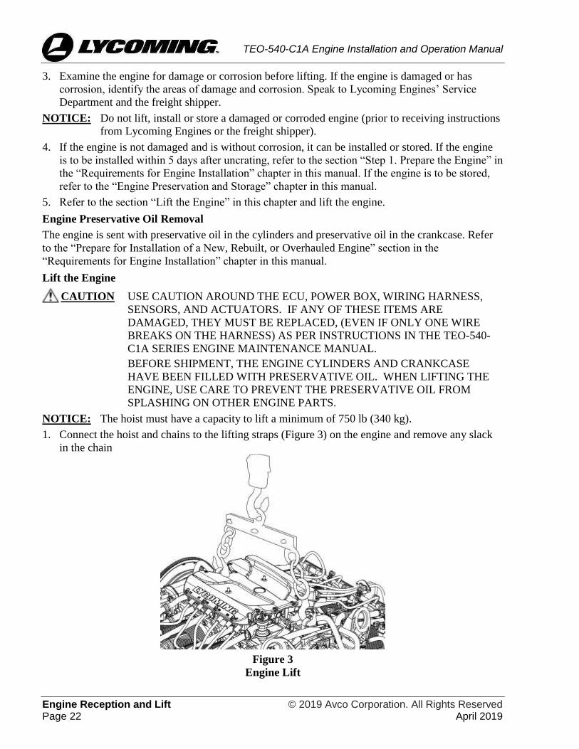
3. Examine the engine for damage or corrosion before lifting. If the engine is damaged or has
corrosion, identify the areas of damage and corrosion. Speak to Lycoming Engines’ Service
Department and the freight shipper.
NOTICE: Do not lift, install or store a damaged or corroded engine (prior to receiving instructions
from Lycoming Engines or the freight shipper).
4. If the engine is not damaged and is without corrosion, it can be installed or stored. If the engine
is to be installed within 5 days after uncrating, refer to the section “Step 1. Prepare the Engine” in
the “Requirements for Engine Installation” chapter in this manual. If the engine is to be stored,
refer to the “Engine Preservation and Storage” chapter in this manual.
5. Refer to the section “Lift the Engine” in this chapter and lift the engine.
Engine Preservative Oil Removal
The engine is sent with preservative oil in the cylinders and preservative oil in the crankcase. Refer
to the “Prepare for Installation of a New, Rebuilt, or Overhauled Engine” section in the
“Requirements for Engine Installation” chapter in this manual.
Lift the Engine
CAUTION USE CAUTION AROUND THE ECU, POWER BOX, WIRING HARNESS,
SENSORS, AND ACTUATORS. IF ANY OF THESE ITEMS ARE
DAMAGED, THEY MUST BE REPLACED, (EVEN IF ONLY ONE WIRE
BREAKS ON THE HARNESS) AS PER INSTRUCTIONS IN THE TEO-540-
C1A SERIES ENGINE MAINTENANCE MANUAL.
BEFORE SHIPMENT, THE ENGINE CYLINDERS AND CRANKCASE
HAVE BEEN FILLED WITH PRESERVATIVE OIL. WHEN LIFTING THE
ENGINE, USE CARE TO PREVENT THE PRESERVATIVE OIL FROM
SPLASHING ON OTHER ENGINE PARTS.
NOTICE: The hoist must have a capacity to lift a minimum of 750 lb (340 kg).
1. Connect the hoist and chains to the lifting straps (Figure 3) on the engine and remove any slack
in the chain
Figure 3
Engine Lift
© 2019 Avco Corporation. All Rights Reserved Engine Reception and Lift April 2019 Page 23
TEO-540-C1A Engine Installation and Operation Manual
CAUTION MAKE SURE THE AREA IS CLEAR WHEN LIFTING THE ENGINE. DO
NOT LIFT FROM THE FRONT, REAR, SIDES OR BOTTOM OF THE
ENGINE. DO NOT LET THE ENGINE HIT ANY OBJECTS TO PREVENT
DAMAGE TO THE ENGINE OR ITS COMPONENTS.
2. Remove the bolts that attach the shipping brackets to the front and rear of the engine.
3. Lift the engine slowly and vertically.
4. When the engine has preservative oil, complete the preservative oil removal procedure now
while the engine is lifted. Refer to the section “Prepare for Installation of a New, Rebuilt, or
Overhauled Engine” section or “Prepare a Stored Engine for Installation” in the “Requirements
for Engine Installation” chapter in this manual.
Engine Reception and Lift © 2019 Avco Corporation. All Rights Reserved Page 24 April 2019
TEO-540-C1A Engine Installation and Operation Manual
This page intentionally left blank.

© 2019 Avco Corporation. All Rights Reserved Requirements for Engine Installation April 2019 Page 25
TEO-540-C1A Engine Installation and Operation Manual
REQUIREMENTS FOR ENGINE INSTALLATION
Overview
NOTICE: If a problem or leak is found on the engine, refer to the TEO-540-C1A Engine
Maintenance Manual for corrective action. If the problem or leak continues, contact
Lycoming Engines.
NOTICE: All requirements identified in this chapter must be completed before the engine can be
installed. These requirements are for a new, rebuilt, overhauled, or stored engine to be
placed into service.
Refer to the separate, standalone Interface Control Document (ICD) which identifies the
format for data transmission and reception required by each subsystem within the
software/hardware interface between the airframe controller and the ECU. The ICD is
available upon request.
As an overview, Table 1 identifies the necessary steps that must be done before the engine can be
installed.
Table 1
Prerequisites for Engine Installation
Step Section References in This Chapter
1 Prepare the Engine
2 Supply Interface Items
3 Remove Components
4 Install Engine Mounting Brackets
Step 1. Prepare the Engine
To prepare a new, rebuilt, or overhauled engine Refer to the section “Prepare for Installation of
a New, Rebuilt, or Overhauled Engine” in this
chapter.
To prepare an engine that has been in storage Refer to the section “Prepare a Stored Engine
for Installation” in this chapter.
Prepare for Installation of a New, Rebuilt, or Overhauled Engine
CAUTION THE ENGINE IS SENT WITH THE WIRING HARNESS AND SENSORS
ATTACHED ON THE ENGINE. THE ECU, POWER BOX, WIRING
HARNESS, AND SENSORS CANNOT BE REPAIRED. IF ANY OF THESE
ITEMS ARE DAMAGED, THEY MUST BE REPLACED. REFER TO THE
TEO-540-C1A ENGINE MAINTENANCE MANUAL.
NOTICE: The engine is sent from the factory with preservative oil in the cylinders and in the
crankcase. A preservation date stamp (usually on the engine box) identifies the date this
oil was added and preservation is good for 60 days afterward. If an intake valve was
open, the preservative oil can get into the induction system of the engine. All
preservative oil must be removed per this depreservation procedure.

Requirements for Engine Installation © 2019 Avco Corporation. All Rights Reserved Page 26 April 2019
TEO-540-C1A Engine Installation and Operation Manual
To prepare the new, rebuilt, or overhauled engine for installation in the airframe:
CAUTION DO NOT TURN THE CRANKSHAFT OF AN ENGINE WITH
PRESERVATIVE OIL BEFORE REMOVAL OF THE PLUGS FROM THE
BOTTOM SPARK PLUG HOLES. OTHERWISE, ENGINE DAMAGE,
CAUSED BY HYDRAULIC LOCK CAN OCCUR.
1. Lift the engine. Refer to the section “Lift the Engine” in the “Engine Reception and Lift” chapter
in this manual.
2. Complete the depreservative procedure as follows:
A. Remove desiccant bags.
B. During the procedure, if any of the dehydrator plugs (which contain crystals of silica gel)
break and the crystals fall into the engine, complete the following per the TEO-540-C1A
Engine Maintenance Manual:
• Disassemble the affected portion of the engine.
• Clean the engine.
C. Put a container under the engine to collect the cylinder preservative oil.
D. Remove the shipping plugs installed in the lower spark plug holes.
E. Remove the desiccant plugs from the upper spark plugs holes.
F. Turn the crankshaft completely three or four complete revolutions to remove the cylinder
preservative oil from the cylinders.
G. Collect the cylinder preservative oil as it drains out of the lower spark plug holes.
H. Tilt the engine to one side until the spark plug holes on that side are vertical.
I. Turn the crankshaft two revolutions and let the oil drain out through the spark plug holes.
J. Tilt the engine to the other side until the spark plug holes on that side are vertical.
K. Turn the crankshaft two revolutions and let the oil drain out through the spark plug holes.
3. Examine the cylinder bores with a borescope for rust and contamination. Refer to the TEO-540-
C1A Engine Maintenance Manual.
4. If any corrosion or unusual conditions are found, speak to Lycoming Engine’s Service
Department.
5. Drain preservative oil from the oil sump:
A. Put a 15-quart (14-liter) capacity
container under the oil sump.
B. Remove the safety wire/cable from the
oil sump drain plugs. Discard the safety
wire/cable.
C. Remove the two oil sump drain plugs
(Figure 1).
D. Drain the remaining preservative oil from
the oil sump into the container.
Figure 1
Oil Sump Drain Plugs and Oil Suction Screen
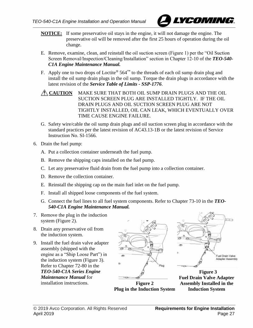
© 2019 Avco Corporation. All Rights Reserved Requirements for Engine Installation April 2019 Page 27
TEO-540-C1A Engine Installation and Operation Manual
NOTICE: If some preservative oil stays in the engine, it will not damage the engine. The
preservative oil will be removed after the first 25 hours of operation during the oil
change.
E. Remove, examine, clean, and reinstall the oil suction screen (Figure 1) per the “Oil Suction
Screen Removal/Inspection/Cleaning/Installation” section in Chapter 12-10 of the TEO-540-
C1A Engine Maintenance Manual.
F. Apply one to two drops of Loctite® 564™ to the threads of each oil sump drain plug and
install the oil sump drain plugs in the oil sump. Torque the drain plugs in accordance with the
latest revision of the Service Table of Limits - SSP-1776.
CAUTION MAKE SURE THAT BOTH OIL SUMP DRAIN PLUGS AND THE OIL
SUCTION SCREEN PLUG ARE INSTALLED TIGHTLY. IF THE OIL
DRAIN PLUGS AND OIL SUCTION SCREEN PLUG ARE NOT
TIGHTLY INSTALLED, OIL CAN LEAK, WHICH EVENTUALLY OVER
TIME CAUSE ENGINE FAILURE.
G. Safety wire/cable the oil sump drain plugs and oil suction screen plug in accordance with the
standard practices per the latest revision of AC43.13-1B or the latest revision of Service
Instruction No. SI-1566.
6. Drain the fuel pump:
A. Put a collection container underneath the fuel pump.
B. Remove the shipping caps installed on the fuel pump.
C. Let any preservative fluid drain from the fuel pump into a collection container.
D. Remove the collection container.
E. Reinstall the shipping cap on the main fuel inlet on the fuel pump.
F. Install all shipped loose components of the fuel system.
G. Connect the fuel lines to all fuel system components. Refer to Chapter 73-10 in the TEO-
540-C1A Engine Maintenance Manual.
7. Remove the plug in the induction
system (Figure 2).
8. Drain any preservative oil from
the induction system.
9. Install the fuel drain valve adapter
assembly (shipped with the
engine as a “Ship Loose Part”) in
the induction system (Figure 3).
Refer to Chapter 72-80 in the
TEO-540-C1A Series Engine
Maintenance Manual for
installation instructions.
Figure 2
Plug in the Induction System
Figure 3
Fuel Drain Valve Adapter
Assembly Installed in the
Induction System

Requirements for Engine Installation © 2019 Avco Corporation. All Rights Reserved Page 28 April 2019
TEO-540-C1A Engine Installation and Operation Manual
10. Examine the spark plugs. If spark plugs are acceptable, install them with a new gasket and
connect the ignition leads. If the spark plugs are dirty, clean them per the procedure in Chapter
05-30 of the TEO-540-C1A Engine Maintenance Manual. If the spark plugs are not acceptable,
install new spark plugs with a new gasket. Refer to Chapter 74-20 in the TEO-540-C1A Engine
Maintenance Manual for the spark plug removal, inspection, and installation procedures.
A. Remove the protectors on the ignition lead ends.
B. Connect the ignition lead ends.
11. If a constant speed propeller is used, remove the expansion plug per instructions in Chapter 72-
20 in the TEO-540-C1A Engine Maintenance Manual.
12. Remove the fuel inlet strainer from the throttle body, clean it with a hydrocarbon-based solvent
such as mineral spirits or equivalent, and re-install the strainer in the throttle body.
13. Examine the fuel supply lines, fuel manifold, and throttle body, to make sure they are clean and
dry.
NOTICE: It is recommended that turbocharged engines be operated with ashless dispersant oil
during and after break-in (the first 50 hours of engine operation or until oil consumption
has stabilized.)
14. Add ashless dispersant oil to a new, rebuilt, or overhauled engine. Refer to Appendix A for the
oil capacity. Refer to the “Add Oil” procedure in the “Engine Installation” chapter in this
manual.
15. Use the correct disposal procedure for collected oil in accordance with local regulations and
environmental protection policy.
Prepare a Stored Engine for Installation
This procedure is for an engine that has been in storage. An engine in storage has preservative oil
which must be removed just prior to engine installation.
Promptly prepare the stored engine for installation into the airframe as follows:
1. Lift the engine. Refer to the section “Lift the Engine” in the “Engine Reception and Lift” chapter
in this manual.
2. Put a container under the engine to collect the cylinder preservative oil.
CAUTION DO NOT TURN THE CRANKSHAFT OF AN ENGINE WITH
PRESERVATIVE OIL BEFORE REMOVAL OF THE BOTTOM SPARK
PLUGS. ENGINE DAMAGE DUE TO HYDRAULC LOCK CAN OCCUR.
3. If the engine has been preserved and/or has been in long-term storage, remove the items used in
preservation as follows:
A. Remove and discard the seals.
B. Remove tape residue with solvent.
C. Remove and discard the dehydrator plugs (if installed).
D. Remove and discard the desiccant bags for the intake and exhaust ports.

© 2019 Avco Corporation. All Rights Reserved Requirements for Engine Installation April 2019 Page 29
TEO-540-C1A Engine Installation and Operation Manual
NOTICE: If any of these plugs break and the crystals fall into the engine, complete the following
procedure per the TEO-540-C1A Engine Maintenance Manual.
• Disassemble the engine as necessary to remove all of the crystals that fell into the engine.
• Clean the engine.
4. Examine the engine for any damage.
5. If the engine is not damaged, go to the next step. If damage is found, identify and correct the
problem. Record findings and corrective action in the engine logbook.
6. Remove the spark plugs or protective plugs from the bottom spark plug holes per instructions in
Chapter 74-20 in the TEO-540-C1A Engine Maintenance Manual.
7. Remove any other moisture-prevention seals and covers from the engine.
CAUTION IF PRESERVATIVE OIL TOUCHES PAINTED SURFACES, REMOVE THE
OIL IMMEDIATELY TO PREVENT DAMAGE TO THE PAINT.
NOTICE: To touch-up paint, refer to Chapter 72-10 in the TEO-540-C1A Engine Maintenance
Manual.
8. Complete the preservative oil removal procedure as follows:
A. Put a container under the engine to collect the cylinder preservative oil.
B. Turn the crankshaft completely three or four revolutions to remove the cylinder preservative
oil from the cylinders.
C. Collect the cylinder preservative oil as it drains out of the lower spark plug holes.
D. Tilt the engine to one side, until the spark plug holes on that side are vertical.
E. Turn the crankshaft two revolutions and let the oil drain out through the spark plug holes.
F. Tilt the engine to the other side until the spark plug holes on that side are vertical.
G. Turn the crankshaft two revolutions and let the oil drain out through the spark plug holes.
9. Examine the cylinder bores with a borescope for rust and contamination. Refer to Chapter 72-30
in the TEO-540-C1A Engine Maintenance Manual.
10. If any corrosion or unusual conditions are found, speak to Lycoming Engines Service
Department.
11. Drain preservative oil from the oil sump:
A. Put a container under the oil sump.
B. Remove the safety wire or safety cable and oil sump drain plugs (Figure 1). Discard the
safety wire/cable.
C. Remove the oil sump drain plugs.
D. Drain the remaining preservative oil from the oil sump into the container.

Requirements for Engine Installation © 2019 Avco Corporation. All Rights Reserved Page 30 April 2019
TEO-540-C1A Engine Installation and Operation Manual
NOTICE: If some preservative oil stays in the engine, it will not damage the engine. The
preservative oil will be removed after the first 25 hours of operation during the oil
change.
E. Remove, examine, clean, and reinstall the oil suction screen (Figure 1) per the “Oil Suction
Screen Removal/Inspection/Cleaning/Installation” section in Chapter 12-10 of the TEO-540-
C1A Engine Maintenance Manual.
F. Apply one to two drops of Loctite® 564™ to the threads of each oil sump drain plug and
install the oil sump drain plugs in the oil sump. Torque the drain plugs in accordance with the
latest revision of the Service Table of Limits - SSP-1776.
CAUTION MAKE SURE THAT THE OIL SUMP DRAIN PLUGS AND THE OIL
SUCTION SCREEN PLUG ARE INSTALLED TIGHTLY. IF THE OIL
DRAIN PLUGS AND OIL SUCTION SCREEN PLUG ARE NOT
TIGHTLY INSTALLED, OIL CAN LEAK, WHICH EVENTUALLY OVER
TIME CAUSE ENGINE FAILURE.
G. Safety wire/cable the oil sump drain plugs and oil suction screen plug in accordance with the
standard practices per the latest revision of AC43.13-1B or the latest revision of Service
Instruction No. SI-1566.
12. Remove the oil filter and install a new oil filter. Refer to Chapter 12-10 in the TEO-540-C1A
Engine Maintenance Manual.
13. If the front expansion plug is installed and a constant speed propeller is to be used, remove the
expansion plug per instructions in the “Crankshaft Disassembly” section of Chapter 72-20 in the
TEO-540-C1A Engine Maintenance Manual.
14. Refer to Chapter 74-20 in the TEO-540-C1A Engine Maintenance Manual to:
A. Examine the spark plugs.
B. If spark plugs are acceptable, install them with a new gasket. If the spark plugs are dirty,
clean them per the procedure in Chapter 05-30 of the TEO-540-C1A Engine Maintenance
Manual. If the spark plugs are not acceptable, install new spark plugs with a new gasket.
C. Remove the protectors on the ignition lead ends.
D. Connect the ignition lead ends.
15. Remove the fuel inlet strainer and clean it with a hydrocarbon-based solvent such as mineral
spirits or equivalent.
16. Examine the fuel supply lines, fuel manifold, and throttle body to make sure they are clean and
dry.
17. Add ashless dispersant oil to a new, rebuilt, or overhauled engine. Record the amount of oil
added. Refer to Appendix A for the oil capacity. Refer to the “Add Oil” procedure in the “Engine
Installation” chapter in this manual.
18. Use the correct procedure for disposal of drained oil and fuel in accordance with local, state,
federal, and environmental protection regulations.
© 2019 Avco Corporation. All Rights Reserved Requirements for Engine Installation April 2019 Page 31
TEO-540-C1A Engine Installation and Operation Manual
Step 2. Supply Interface Items
For engine installation, the airframe manufacturer must supply the following items:
Required for initial engine installation:
• Correctly-sized hose for the fuel pump supply and fuel pump vent line
• Correctly-sized fuel return line (from fuel pressure regulator)
• Airframe fuel pump (fuel pump independently controlled by a circuit breaker with access by
the flight crew for fire and emergency procedures)
• Auxiliary fuel pump output wired to a three-position switch to drive a relay that controls the
airframe boost pump
• Airframe fuel pump switch with ON/OFF/AUTO positions
• Independent Fuel Shut-Off Valve (to meet engine shutdown requirements)
• 10-micron fuel filter (with a bypass)
• Air cleaner
• Oil cooler and appropriate oil hoses
• Bonded rubber mounts
• Hardwired lights to display warnings and cautions from the system
o No Take-Off (NTO) Primary annunciator
o NTO Secondary annunciator
o Time-Limited Operation (TLO) annunciator
o Fault Found (FFL) annunciator
• Pre-Flight Test (PFT) pushbutton (pushbutton with illumination capability or pushbutton with
separate illumination)
• Ignition (dual pole single throw) switches
• Aircraft battery used as an EECS backup
• Starter wiring and controls
• Two ground straps from the ground lugs for the ECU - refer to “Step 11. Attach Ground
Straps” in the Engine Installation chapter
• Two ground straps for the Power Box
• Airframe engine mount ground straps
• Three low impedance ground straps from the engine case to the engine mounting frame
NOTICE: Mounting the ECU to the Power Box requires four 1/4-20 bolts with a maximum
length of 1/2 inch.
• A physical location for the mount of the Power Box and the ECU
• A connection point to attach the wiring harness to the airframe
• Airframe mate to the four-pin plug on the wiring harness can be a wall mount, cable
connection, box mount, or jam nut receptacle
• 37-pin connector interface to the airframe engine wiring harness
• Communications interface to receive EECS instrumentation data
• A propeller.

Requirements for Engine Installation © 2019 Avco Corporation. All Rights Reserved Page 32 April 2019
TEO-540-C1A Engine Installation and Operation Manual
Step 3. Remove Components
It could be necessary to temporarily remove a component, such as an exhaust pipe, to install the
engine in its compartment on the aircraft.
Remove only the components necessary to enable engine installation.
The component(s) will be re-installed after the engine is installed.
Step 4. Install Engine Mounting Brackets
If not already done, install the four engine
mounting brackets on the engine. If the engine
mounting brackets were removed from a
previously installed engine, examine the
brackets per the “Engine Mount Inspection”
section in Chapter 72-00 of the TEO-540-C1A
Engine Maintenance Manual.
The engine is installed in the aircraft using the
rear top and bottom engine mounts. There are
no mounts in the front of the engine.
Figure 4
Engine Mounts
© 2019 Avco Corporation. All Rights Reserved Engine Installation April 2019 Page 33
TEO-540-C1A Engine Installation and Operation Manual
ENGINE INSTALLATION
Engine Installation Overview
NOTICE: All requirements identified in the chapter “Requirements for Engine Installation” must
be completed before engine installation.
To install the engine, refer to Table 1 and the section reference in this chapter for each step.
Table 1
Engine Installation Steps and References
Step Section References in This Chapter
1 Install the ECU
2 Install the Power Box
3 Install the Engine on Mounts
4 Connect the Wiring Harnesses
5 Connect the Power Control Linkage
6 Install External Accessories
7 Install the Alternator
8 Install the Propeller
9 Connect Fuel Hoses
10 Connect Oil Hoses
11 Attach Ground Straps
12 Install Components That Had Been Removed Before Engine Installation
and Any Additional Ship Loose Components
13 Make Remaining Engine Connections
14 Install Baffling
15 Add Oil
16 Engine Pre-Oil Procedure
17 Add Fuel (to aircraft as necessary)
18 Make RPM Measurements
19 Final Installation Inspection
20 Close Engine Compartment

Engine Installation © 2019 Avco Corporation. All Rights Reserved Page 34 April 2019
TEO-540-C1A Engine Installation and Operation Manual
Step 1. Install the ECU
CAUTION THE ENGINE CONTROL UNIT (ECU) HAS A SPECIFIC CONFIGURATION
FOR EACH ENGINE AND AIRFRAME. THE ECU AND ENGINE HAVE
FACTORY-DESIGNATED SERIAL NUMBERS THAT GO TOGETHER.
MAKE SURE THE SERIAL NUMBERS ON THE ECU AND THE ENGINE
AGREE WITH SERIAL NUMBERS IDENTIFIED IN THE
DOCUMENTATION SENT WITH THE ENGINE. IF THE SERIAL
NUMBERS DO NOT AGREE, DO NOT INSTALL THE ECU. CONTACT
LYCOMING ENGINES IMMEDIATELY.
Install the ECU with the correct serial number on the airframe in its designated location in
accordance with the wiring diagram. Also refer to Appendix B in the TEO-540-C1A Engine
Maintenance Manual for additional details.
CAUTION THERE MUST NOT BE EXCESSIVE CONVECTIVE OR RADIANT
HEAT IMPINGEMENT ON THE ECU AS A RESULT OF THE
INSTALLATION.
NOTICE: Torque the ECU fasteners in accordance with the latest revision of the Service Table
of Limits - SSP-1776.
Step 2. Install the Power Box
1. Install the Power Box with the correct serial number on the airframe in its designated location
in accordance with the wiring diagram. Refer to Appendix B in the TEO-540-C1A Engine
Maintenance Manual for additional details.
NOTICE: Mounting the ECU to the Power Box requires four 1/4-20 bolts with a maximum
length of 1/2 inch.
2. The Power Box can be installed in a stacked configuration.
CAUTION THERE MUST NOT BE ANY EXCESSIVE THERMAL CONVECTIVE OR
RADIANT HEAT IMPINGEMENT ON THE POWER BOX AS A RESULT
OF THE INSTALLATION.
NOTICE: Torque the Power Box fasteners in accordance with the latest revision of the Service
Table of Limits - SSP-1776.
Step 3. Install the Engine on Mounts
CAUTION MAKE SURE THAT THE ENGINE MOUNTS ARE ALIGNED AND NOT
BENT OR DEFORMED. IF THE ENGINE IS INSTALLED ON DEFORMED
ENGINE MOUNTS OR MISALIGNED, THE ENGINE CAN BE PUT UNDER
UNUSUAL FORCE WHICH CAN CAUSE MALFUNCTION.
USE CAUTION AROUND THE ECU, POWER BOX, WIRING HARNESS,
SENSORS, AND ACTUATORS. IF ANY OF THESE ITEMS ARE
DAMAGED, THEY MUST BE REPLACED, (EVEN IF ONLY ONE WIRE
BREAKS ON THE HARNESS) AS PER INSTRUCTIONS IN THE TEO-540-
C1A SERIES ENGINE MAINTENANCE MANUAL.
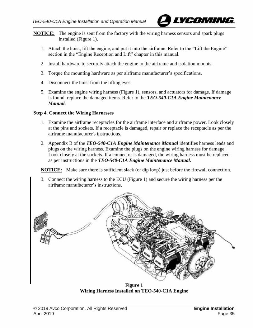
© 2019 Avco Corporation. All Rights Reserved Engine Installation April 2019 Page 35
TEO-540-C1A Engine Installation and Operation Manual
NOTICE: The engine is sent from the factory with the wiring harness sensors and spark plugs
installed (Figure 1).
1. Attach the hoist, lift the engine, and put it into the airframe. Refer to the “Lift the Engine”
section in the “Engine Reception and Lift” chapter in this manual.
2. Install hardware to securely attach the engine to the airframe and isolation mounts.
3. Torque the mounting hardware as per airframe manufacturer’s specifications.
4. Disconnect the hoist from the lifting eyes.
5. Examine the engine wiring harness (Figure 1), sensors, and actuators for damage. If damage
is found, replace the damaged items. Refer to the TEO-540-C1A Engine Maintenance
Manual.
Step 4. Connect the Wiring Harnesses
1. Examine the airframe receptacles for the airframe interface and airframe power. Look closely
at the pins and sockets. If a receptacle is damaged, repair or replace the receptacle as per the
airframe manufacturer's instructions.
2. Appendix B of the TEO-540-C1A Engine Maintenance Manual identifies harness leads and
plugs on the wiring harness. Examine the plugs on the engine wiring harness for damage.
Look closely at the sockets. If a connector is damaged, the wiring harness must be replaced
as per instructions in the TEO-540-C1A Engine Maintenance Manual.
NOTICE: Make sure there is sufficient slack (or dip loop) just before the firewall connection.
3. Connect the wiring harness to the ECU (Figure 1) and secure the wiring harness per the
airframe manufacturer’s instructions.
Figure 1
Wiring Harness Installed on TEO-540-C1A Engine

Engine Installation © 2019 Avco Corporation. All Rights Reserved Page 36 April 2019
TEO-540-C1A Engine Installation and Operation Manual
NOTICE: The collar on the threaded plugs should only be tightened by hand. Do not use
pliers, adjustable pliers, or any other tool to tighten the collar on the threaded plugs.
4. Tighten the collar on the threaded plugs. The plugs must be tightened, by hand, until the red
colored band on the receptacle (Figure 2) cannot be seen from the side of the connection
(Figure 3).
Figure 2
Red Colored Band on the Receptacle
Figure 3
Correctly Installed Threaded Plug
5. Ensure all other necessary connections are made to the wiring harness per the airframe
manufacturer’s wiring diagram.
6. Connect the wiring to the starter and PMA per the airframe manufacturer’s instructions.
CAUTION NO EECS PARTS OR HARNESS CAN BE INTERCHANGED BETWEEN
ENGINES UNLESS AGREED UPON BY LYCOMING ENGINES.
NOTICE: All the plugs on the wiring harness are uniquely keyed and must be in the correct
orientation for the plug to install correctly in the receptacle.
7. Connect the two harness plugs, primary and secondary, identified as CIP-P and CAP-S to the
compressor inlet pressure sensors installed in the induction system between the airframe
induction air filter and the turbocharger compressor inlet. Install the connector CIP-P to the
sensor for the turbocharger inlet on the left side (exhaust bypass valve side) of the engine.
8. After the engine and airframe engine harnesses are installed, examine the connectors on both
wire harnesses for damage. Look closely at the connector contacts (pins and sockets),
connector body, and back shell. If any part of a connector is damaged on the engine harness,
replace the harness per instructions in the latest revision of the TEO-540-C1A Engine
Maintenance Manual. If a connector is damaged on the engine airframe wiring harness,
replace the harness per instructions in the latest revision of the Aircraft Maintenance
Manual.
Step 5. Connect the Power Control Linkage
Connect the cable to the power control linkage for the engine.

© 2019 Avco Corporation. All Rights Reserved Engine Installation April 2019 Page 37
TEO-540-C1A Engine Installation and Operation Manual
Step 6. Install External Accessories
NOTICE: Accessory Drive Pads Nos. 1, 2, and 3 and AND 20000 are spline compatible
accessories with mounting flanges.
1. Remove the cover plate and gasket.
2. Install the accessory on the supplied pad in accordance with the airframe manufacturer’s
instructions.
NOTICE: A propeller governor drive pad is on the upper left front of the crankcase.
3. If necessary, install the propeller governor; use the manufacturer’s supplied gasket and
hardware. Refer to the TEO-540-C1A Engine Maintenance Manual.
Step 7. Install the Alternator
1. The alternator is supplied in a kit.
2. In accordance with Chapter 72-70 in the TEO-540-C1A Engine Maintenance Manual:
A. Install the alternator.
B. Install the alternator belt.
C. Complete an alternator belt tension check and adjust the alternator belt as needed.
Step 8. Install the Propeller
Install the propeller in accordance with the propeller and airframe manufacturer’s instructions.
Step 9. Connect the Fuel Hoses
1. Remove unwanted material from the aircraft fuel strainer. Let a minimum of 1 gallon (3.8
liters) of fuel flow through the strainer, aircraft fuel filter and fuel supply line.
WARNING REMOVE ANY CONTAMINATION FROM AIRCRAFT FUEL TANKS
AND FUEL HOSES. FAILURE TO REMOVE ALL CONTAMINATION
CAN CAUSE PREMATURE FUEL FILTER FAILURE OR INCORRECT
FUEL SYSTEM OPERATION.
2. Before connection of the main fuel inlet line to the fuel pump, remove all contaminants from
aircraft fuel tanks and fuel hoses.
3. Make sure that the airframe manufacturer has a fuel filter installed on the airframe. (The
engine has a small back-up fuel filter - which is not to be used as the primary fuel filter.)
4. Remove protective caps from the main fuel inlet.
5. Connect the main fuel inlet line to the fuel pump. Torque the connection as per the airframe
manufacturer's instructions.
6. Follow these required guidelines for making fuel hose connections.
A. Make sure that each fuel hose is intact, not bent or damaged, and does not have any kinks
or dents.

Engine Installation © 2019 Avco Corporation. All Rights Reserved Page 38 April 2019
TEO-540-C1A Engine Installation and Operation Manual
NOTICE: Refer to Chapter 73-10 in the TEO-540-C1A Engine Maintenance Manual for
suggested routing and configuration arrangement diagrams for fuel hoses and
fuel injector lines on this engine. The fuel hose and fuel injector line
configuration diagram is for reference only. If specific fuel hose and fuel
injector line routing information is in airframe documentation, follow the
airframe instruction. Fuel hoses and fuel injector lines must be examined during
every visual inspection as per the TEO-540-C1A Engine Maintenance Manual.
B. Make sure cushioned clamps securely attach fuel hoses and fuel injector lines (to dampen
vibration during flight). Do NOT use plastic tie straps in place of cushioned clamps.
WARNING DO NOT ROUTE FUEL HOSES CLOSE TO HEAT SOURCES. HEAT
CAN CAUSE FUEL VAPORIZATION IN THE FUEL HOSES OR CAN
DAMAGE THE FUEL HOSE AND CAUSE A FUEL LEAK WHICH
COULD LEAD TO CATASTROPHIC ENGINE FAILURE.
C. Do not let fuel hoses touch the engine or airframe baffle hardware. There must be a
minimum clearance of 3/16 in. (4.76 mm) between a fuel hose and any engine or airframe
surface.
Step 10. Connect Oil Hoses
CAUTION MAKE SURE THERE ARE NO SHARP BENDS OR KINKS IN THE OIL
HOSE ROUTING TO PREVENT INTERRUPTIONS TO OIL FLOW. DO NOT
ROUTE OIL HOSES CLOSE TO HEAT SOURCES.
1. Connect the oil hose from the oil sump to the wastegate.
2. Connect the oil hoses from the airframe-supplied oil cooler.
3. Clean each oil hose section and install it in the respective areas. Make sure the oil hose
routing is smooth, without sharp bends, kinks or helical twists.
4. When making the following oil hose connections:
A. Align the oil hose with the fitting for best orientation (without kinks or sharp bends).
B. Torque the fitting to the torque value in the latest revision of the Service Table of Limits -
SSP-1776.
Step 11. Attach Ground Straps
NOTICE: Ground straps are necessary to make sure that the EECS operates correctly, and that the
sensors and actuators have the necessary ground for correct operation. The ground
straps are a primary line of defense in the event of a lightning strike to the aircraft.
1. Connect two ground straps (with at least 0.012 in2 (8 mm2) of cross sectional area -
approximately equivalent to AWG 8) from the dedicated grounding lugs (the non-colored
pads) on the ECU to the dedicated airframe ground bus.
2. Connect two ground straps (with at least 0.012 in2 (8 mm2) of cross sectional area -
approximately equivalent to AWG 8) from the dedicated grounding lugs (the non-colored
pads) on the Power Box to the dedicated airframe ground bus.

© 2019 Avco Corporation. All Rights Reserved Engine Installation April 2019 Page 39
TEO-540-C1A Engine Installation and Operation Manual
3. In accordance with FAA guidelines on HIRF and Lightning, install three low impedance
grounding jumpers of 0.025 in2 (16 mm2) minimum conductive areas from the engine case to
the engine mounting frame. The grounding jumpers must be less than 12 in. (30 cm) long.
4. Connect low impendence grounding jumpers between the engine mount and airframe, if
necessary, to ensure a conductive path from engine to airframe equivalent to the three low
impedance grounding jumpers specified in the previous step.
Step 12. Install Components That Had Been Removed Before Engine Installation and Any
Additional Ship Loose Components
1. Install any component that was removed to enable engine installation.
2. Install any remaining components that were shipped loose with the engine.
Step 13. Make Remaining Engine Connections
1. Connect EECS wiring harness to airframe adapter interface wiring harness.
2. Make engine connections to accessories.
3. Make engine connections to wires and cables.
4. Make engine connections to ducts and cowling.
5. Make engine connections to breather, hoses and pipes.
6. Connect alternator blast tubes to a source of cooling air sufficient to prevent the alternator
temperature from increasing above maximum limits set by the alternator manufacturer.
Step 14. Install Baffling
Install baffling around the engine compartment.
Step 15 Add Oil
CAUTION OIL IN THE CORRECT QUANTITY AND OF THE CORRECT VISCOSITY
FOR THE CORRESPONDING AMBIENT TEMPERATURE MUST BE
ADDED TO THE ENGINE FOR CORRECT LUBRICATION ESSENTIAL TO
ENGINE OPERATION. REFER TO APPENDIX A FOR OIL TYPES AND OIL
SUMP CAPACITY TO HAVE THE CORRECT QUANTITY AND TYPE OF
OIL TO ADD TO THE ENGINE.
Add ashless dispersant oil to turbocharged engines, as specified in Appendix A. Refer to Chapter 12-
10 in the TEO-540-C1A Engine Maintenance Manual for the procedure to add oil.
NOTICE: To accurately calculate oil consumption, every time oil is added, record the quantity of
oil added in the engine logbook.
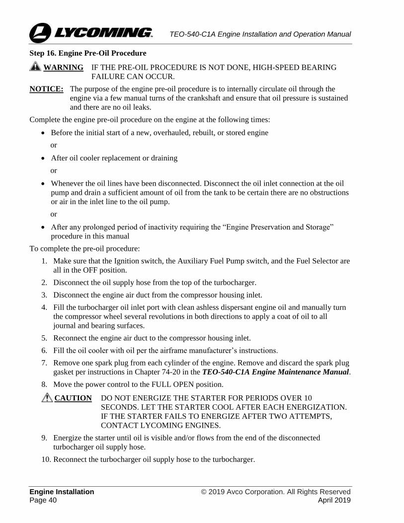
Engine Installation © 2019 Avco Corporation. All Rights Reserved Page 40 April 2019
TEO-540-C1A Engine Installation and Operation Manual
Step 16. Engine Pre-Oil Procedure
WARNING IF THE PRE-OIL PROCEDURE IS NOT DONE, HIGH-SPEED BEARING
FAILURE CAN OCCUR.
NOTICE: The purpose of the engine pre-oil procedure is to internally circulate oil through the
engine via a few manual turns of the crankshaft and ensure that oil pressure is sustained
and there are no oil leaks.
Complete the engine pre-oil procedure on the engine at the following times:
• Before the initial start of a new, overhauled, rebuilt, or stored engine
or
• After oil cooler replacement or draining
or
• Whenever the oil lines have been disconnected. Disconnect the oil inlet connection at the oil
pump and drain a sufficient amount of oil from the tank to be certain there are no obstructions
or air in the inlet line to the oil pump.
or
• After any prolonged period of inactivity requiring the “Engine Preservation and Storage”
procedure in this manual
To complete the pre-oil procedure:
1. Make sure that the Ignition switch, the Auxiliary Fuel Pump switch, and the Fuel Selector are
all in the OFF position.
2. Disconnect the oil supply hose from the top of the turbocharger.
3. Disconnect the engine air duct from the compressor housing inlet.
4. Fill the turbocharger oil inlet port with clean ashless dispersant engine oil and manually turn
the compressor wheel several revolutions in both directions to apply a coat of oil to all
journal and bearing surfaces.
5. Reconnect the engine air duct to the compressor housing inlet.
6. Fill the oil cooler with oil per the airframe manufacturer’s instructions.
7. Remove one spark plug from each cylinder of the engine. Remove and discard the spark plug
gasket per instructions in Chapter 74-20 in the TEO-540-C1A Engine Maintenance Manual.
8. Move the power control to the FULL OPEN position.
CAUTION DO NOT ENERGIZE THE STARTER FOR PERIODS OVER 10
SECONDS. LET THE STARTER COOL AFTER EACH ENERGIZATION.
IF THE STARTER FAILS TO ENERGIZE AFTER TWO ATTEMPTS,
CONTACT LYCOMING ENGINES.
9. Energize the starter until oil is visible and/or flows from the end of the disconnected
turbocharger oil supply hose.
10. Reconnect the turbocharger oil supply hose to the turbocharger.

© 2019 Avco Corporation. All Rights Reserved Engine Installation April 2019 Page 41
TEO-540-C1A Engine Installation and Operation Manual
11. Pre-oil start cycle: Energize the starter for 10 to 15 seconds and look for evidence of oil
pressure of at least 20 psi (138 kPa) within 10 to 15 seconds.
If there is no oil pressure within 10 to 15 seconds, stop energizing the starter. Wait at least 30
seconds and repeat the pre-oil start cycle.
Up to six consecutive pre-oil start cycles can be done. Afterwards let the starter cool for 30
minutes. If stable oil pressure is not achieved, stop pre-oiling and contact Lycoming Engines.
NOTICE: Unstable oil pressure or oil pressure less than 20 psi (138 kPa) could be an
indication of obstructed or interrupted oil flow or air in the oil lines. Lack of
pressure build-up or rapid drop-off of pressure is an indication of the presence of air
in the line and the engine is not getting oil. To correct this problem, disconnect the
inlet lines at the turbocharger and exhaust valve guide oil. Turn the starter again
until oil pressure is shown.
12. If oil pressure of at least 20 psi (138 kPa) was sustained in the previous step, repeat the pre-
oil start cycle to make sure oil pressure holds stable and that there is no sudden drop in oil
pressure. If oil pressure is not stable or drops suddenly, stop pre-oiling, and contact
Lycoming Engines.
NOTICE: A new spark plug gasket must be installed whether a new or acceptable re-used
spark plug is to be installed.
13. Once the minimum oil pressure of 20 psi (138 kPa) is shown on the oil pressure gauge, re-
install the spark plugs each with a new gasket, and connect the ignition leads to all spark
plugs per instructions in Chapter 74-20 of the TEO-540-C1A Engine Maintenance Manual.
14. Within 3 hours of completing the pre-oil procedure, complete the remaining steps in this
chapter, then start and operate the engine for 3 minutes at approximately 1000 rpm.
Step 17. Add Fuel
WARNING DO NOT USE A LOWER OCTANE OR INCORRECT GRADE OR TYPE OF
FUEL (DIFFERENT FROM FUEL IDENTIFIED IN APPENDIX A). USE OF
INCORRECT FUEL CAN LEAD TO DETONATION, POWER LOSS, AND
ENGINE DAMAGE.
Add the fuel identified in Appendix A to the aircraft.
Step 18. Make RPM Measurements
1. There is no provision for a mechanical tachometer drive.
2. The airframe manufacturer must calibrate the engine speed (rpm) measurement.
Step 19. Final Installation Inspection
Complete the Engine Installation Checklist at the end of this chapter.
Step 20. Close Engine Compartment
1. Make sure that there are no tools or unwanted materials in the engine or engine nacelle or
compartment.
2. Install all cowling and nacelle access panels to close the engine compartment securely. Refer
to the airframe manufacturer’s instructions and specified torque values.

Engine Installation © 2019 Avco Corporation. All Rights Reserved Page 42 April 2019
TEO-540-C1A Engine Installation and Operation Manual
Engine Installation Checklist
Engine Installation Checklist
Requirement Done Comment
Make sure the engine is securely installed on the
engine mounts. Make sure that the hardware that
attaches the engine to the engine mounts is torqued
as per the airframe manufacturer’s specified torque
values.
Make sure the power control linkage is connected.
Make sure all ground straps are connected to the
engine mounts.
Make sure the accessories and alternator are
installed.
Make sure all spark plugs are installed.
Make sure all wiring harnesses and wiring
connections have been made.
Make sure the wiring harness and sensors are
attached to the engine.
Make sure the ECU and Power Box are installed.
Make sure baffles have been installed.
Make sure fuel hoses and oil hoses are connected
and that there are no leaks. Make sure clamps are
securely installed on the fuel hoses.
Make sure oil has been added to engine and the oil
quantity added is recorded to calculate oil
consumption.
Make sure the engine pre-oil procedure has been
completed.
Make sure fuel has been added to aircraft fuel tanks.
Make sure the rpm measurements have been made.
WARNING TO PREVENT CATASTROPHIC FAILURE FROM FOREIGN OBJECT
DEBRIS (FOD), MAKE SURE THAT THERE ARE NO TOOLS IN THE
ENGINE NACELLE AND COMPARTMENT.
Remove any tools or unwanted materials from the
engine compartment.
Close the engine compartment.

© 2019 Avco Corporation. All Rights Reserved Field Run-In April 2019 Page 43
TEO-540-C1A Engine Installation and Operation Manual
FIELD RUN-IN
Either a field run-in or a factory run-in procedure is done to ensure that the engine meets all
specifications and is operating correctly. Since a run-in is done on new, rebuilt or overhauled
engines shipped from Lycoming Engines, the field run-in is not necessary. However, a field run-in
procedure herein is done only on engines in the field after any of the following:
• A field-overhauled engine is installed
• Field disassembly and reassembly of the engine for any repair, component replacement, or
inspection that requires separation of the crankcase halves
NOTICE: Refer to the latest revision of Service Instruction No. SI-1427 for any additional details
on the field run-in.
Field Run-In Procedure
Field run-in of fixed wing aircraft includes two procedures, “Preparation for Ground Operational
Test with Engine Installed in Aircraft” and “Ground Operational Test.”
1. Preparation for Ground Operational Test with Engine Installed in Aircraft
NOTICE: The “Engine Pre-Oil Procedure” in the “Engine Installation” chapter in this manual
must be already completed before the ground operational test can be done.
A. Ensure that all engine instrumentation is calibrated to ensure accuracy.
CAUTION MAKE SURE THAT ALL VENT AND BREATHER LINES ARE
INSTALLED CORRECTLY AND ARE SECURELY IN PLACE IN
ACCORDANCE WITH THE AIRFRAME MAINTENANCE MANUAL.
B. Install engine intercylinder baffles, airframe baffles/seals, and cowling. All baffles and
seals must be in new or good condition to ensure sufficient cooling airflow differential
across the engine.
C. For optimum cooling during the ground operational test, use a test club propeller. If a test
club is unavailable, a regular flight propeller can be used as long as cylinder head
temperatures are monitored closely.
2. Ground Operational Test
Complete this test while the engine is operating.
WARNING IF THE ENGINE IS OPERATED AT LOW OR NO OIL PRESSURE, THE
ENGINE CAN MALFUNCTION OR STOP.
CAUTION ON TURBOCHARGED ENGINES, OPERATE THE ENGINE AT LOW
SPEED UNTIL THE OIL PRESSURE IS STABLE. OVERBOOST CAN
OCCUR IF THE TURBOCHARGER CONTROL SYSTEM EXPERIENCES
UNUSUAL OIL PRESSURES DUE TO AN OIL TEMPERATURE BELOW
THE MINIMUM OPERATION TEMPERATURE OF 140ºF (60ºC).
NOTICE: Before the ground operational test, the oil cooler system must not have any air locks.
A. Before the start of the ground operational test, examine the oil cooler, propeller, and
governor for metal contamination. These parts must be clean and free of contamination
before the ground operational test can begin. If the engine had failed before overhaul, the
oil cooler, propeller, and governor must be replaced or cleaned and examined by an
approved repair facility.

Field Run-In © 2019 Avco Corporation. All Rights Reserved Page 44 April 2019
TEO-540-C1A Engine Installation and Operation Manual
B. Put the aircraft in a position facing the wind.
C. Start the engine. If either you do not see oil pressure (greater than 0) indication within 10
seconds after engine start or oil pressure does not continue to increase above the
published minimum pressure (per Appendix A, Table A-2) in the next 20 seconds, stop
the engine. Identify and correct the problem before another engine start.
D. Monitor the oil pressure and oil temperature. If low or no oil pressure is noted, stop the
engine and identify the cause.
E. Operate the engine at 750 rpm for 1 minute; slowly increase the speed to 1000 rpm in 3
minutes.
F. Let the engine operate at 1000 rpm for approximately 3 minutes.
G. Look for any illuminated caution or warning lights in the cockpit.
H. If oil pressure is sufficient, operate the engine at 1000 RPM until the oil temperature is
stable or is at 140°F (60°C). After warm-up, the oil pressure is not to be less than the
minimum specified pressure per Appendix A.
I. Increase the engine speed to 1500 RPM and operate the engine at that speed for 15
minutes.
J. Make sure the cylinder head temperature, oil temperature, and oil pressure are within the
specified limits in Appendix A of this manual.
NOTICE: Extended ground operation can cause excessively high cylinder head and/or oil
temperatures.
If any malfunction occurs, stop the engine and let it cool. Identify and correct the
cause before continuation of the ground operational test.
K. If the engine is equipped with a mechanical propeller governor, complete a cycle of the
propeller blade pitch positions as applicable per the airframe manufacturer’s
recommendations.
L. Operate the engine to full-static aircraft recommended power (in Appendix A) for up to
10 seconds.
M. After engine operation at full power, slowly decrease the RPM to idle and let the engine
stabilize.
NOTICE: As needed, set fuel controls on new, rebuilt, or overhauled engine to 50 to 100
rpm higher than usual idle speed (600 to 700 rpm) for the first 25 hours of
operation - then adjust to the usual setting after the first 25 hours of operation.
N. Shut down the engine per “Step 4. Engine Stop” procedure in the “Engine Initiation”
chapter of this manual.
O. After shutdown, examine the engine for oil and fuel leaks. Identify and correct the cause
of any leaks.
P. Per Chapter 12-10 in the TEO-540-C1A Engine Maintenance Manual:
(1) Complete an oil change and replace the oil filter.

© 2019 Avco Corporation. All Rights Reserved Field Run-In April 2019 Page 45
TEO-540-C1A Engine Installation and Operation Manual
(2) Remove, clean, and install the oil suction screen.
(3) Add the correct grade and quantity of oil to the engine per the latest revision of
Service Instruction No. SI-1014 and Appendix A of this manual.
WARNING IF DURING AN OPERATIONAL TEST OR ENGINE IDLE
ANNUNCIATORS ILLUMINATE OR ANY OPERATIONAL
PROBLEMS OCCUR, IDENTIFY THE FAULT(S) USING THE
FST, CORRECT THE CONDITION(S), AND CLEAR THE
FAULT(S) OR CONTACT LYCOMING ENGINES.
3. Proceed to the “Engine Initiation” chapter for the remaining procedures to put the engine into
service.

Field Run-In © 2019 Avco Corporation. All Rights Reserved Page 46 April 2019
TEO-540-C1A Engine Installation and Operation Manual
This page intentionally left blank.

© 2019 Avco Corporation. All Rights Reserved Engine Initiation April 2019 Page 47
TEO-540-C1A Engine Installation and Operation Manual
ENGINE INITIATION
Engine Initiation
Engine initiation includes the procedures in Table 1 which are to be done in the field on any of the
following newly installed Lycoming engines:
• Any new, overhauled, or rebuilt engine from the factory and field-overhauled engines
• Engine taken out of storage (if not run-in when put in storage)
• An engine which has been disassembled/re-assembled
NOTICE: All of the procedures in Table 1 are mandatory and must be done prior to the first flight
with the engine.
Table 1
Engine Initiation Procedures for All Lycoming Engines
Step Section References in This Chapter
1 Pre-Flight Inspection for Engine Initiation
2 Pre-Start Inspection
3 Engine Start
4 Operational Test
5 Engine Run-Up
6 Complete the Pre-Flight Test
7 Engine Stop
8 Break-In/Flight Test/50-Hour Operation
9 Required Inspections During Break-In
Warranty Requirement
WARNING AS ONE OF THE CONDITIONS FOR THE ENGINE WARRANTY, YOU
MUST OPERATE THIS ENGINE IN ACCORDANCE WITH
SPECIFICATIONS IN THIS MANUAL. YOU ALSO MUST COMPLETE
THE RECOMMENDED SERVICE AND MAINTENANCE PROCEDURES IN
ACCORDANCE WITH THE TEO-540-C1A ENGINE MAINTENANCE
MANUAL FOR THIS ENGINE.
Step 1. Pre-Flight Inspection for Engine Initiation
Copy and complete the Pre-Flight Inspection Checklist for Engine Initiation.
NOTICE: Refer to the “Pilot Controls and Annunciators” chapter in this manual for dashboard
controls.

Engine Initiation © 2019 Avco Corporation. All Rights Reserved Page 48 April 2019
TEO-540-C1A Engine Installation and Operation Manual
Pre-Flight Inspection Checklist for Engine Initiation
Engine Model Number TEO-540-C1A Engine Serial Number:___________________
Engine Time:________________________ Date Inspection Done:________________________
Inspection done by:___________________________
Requirement Comments Done
Make sure that all switches are OFF or NORM.
Make sure the NTO light or any other EECS light are not
illuminated, which are an indication not to take-off.
Make sure that the power control and alternate air
controls are free to move in the full range of travel.
Make sure the alternate air supply operates correctly.
Make sure the aircraft battery has a full charge, especially
in sub-freezing temperatures.
NOTICE: The oil sump capacity and the minimum quantity for flight and on the ground are
identified in Appendix A.
Measure the engine oil level before every flight to make
sure there is sufficient oil in the engine. If the oil level is
too low (after adding oil), look for any oil leaks. Identify
and correct the cause of any oil leak.
Complete an oil level check per
Chapter 12-10 in the TEO-540-
C1A Engine Maintenance
Manual.
Make sure that the engine crankcase breather is attached
tightly and that there are no blockages to the breather air
flow.
Remove any blockage to the air
flow. Identify and correct the
cause of any blockage.
If the engine is newly installed or is to be put back into
service after long-term storage, make sure that the pre-oil
procedure was done.
Refer to section "Step 17.
Engine Pre-Oil Procedure" in
the "Engine Installation"
chapter in this manual.
Make sure that the induction air filter is clean and
securely in place.
Examine the propeller and propeller hub for cracks, oil
leaks, and security. If cracks are found, refer to the
propeller manufacturer's instructions. Flight is not
allowed with cracks in the propeller or propeller hub. If
oil leaks are found, contact the propeller manufacturer.

© 2019 Avco Corporation. All Rights Reserved Engine Initiation April 2019 Page 49
TEO-540-C1A Engine Installation and Operation Manual
Pre-Flight Inspection Checklist for Engine Initiation (Cont.)
Examine the engine and cowl for indication of fuel and
engine oil leaks.
Identify and correct the cause of
any leaks.
Make sure that all baffles and baffle seals are installed in
the correct position and are serviceable.
Look in the engine compartment and cowling for
unwanted material, loose, missing fittings, clamps and
connections. Examine for restrictions to cooling airflow.
Remove any unwanted material.
Tighten any loose connections
per torque values supplied by
the aircraft manufacturer.
As necessary, add fuel specified (in Appendix A) to the
aircraft in accordance with the airframe manufacturer’s
instructions.
WARNING DO NOT ROUTE FUEL HOSES OR OIL HOSES CLOSE TO HEAT
SOURCES. HEAT CAN DAMAGE THE FUEL AND OIL HOSES AND
CAUSE A LEAK WHICH COULD LEAD TO CATASTROPHIC ENGINE
FAILURE.
Examine fuel and lubrication lines:
A. Make sure that each fuel hose and oil hose is
intact, not bent or damaged, and does not have
any kinks or dents.
B. Make sure that the fuel hoses and oil hoses are
securely connected.
C. Make sure the clamps are tightly attached to
support the fuel and oil hoses and to prevent
movement from vibration. Do NOT use plastic tie
straps in place of cushioned clamps.
D. Do not let fuel and oil hoses touch the engine or
aircraft baffle hardware. There must be a
minimum of clearance of 3/16 in. (4.76 mm)
between fuel and oil hoses and any engine or
aircraft surface.
NOTICE: Record any problems found and corrective action taken in the engine logbook. Record
the magnitude and duration of a problem and any out-of-tolerance values.
Correct all problems before engine start. Refer to the
"Engine Conditions" chapter in this manual.
Complete a flight test per the section “Step 8. Break-
In/Flight Test/50-Hour Operation” in this chapter.

Engine Initiation © 2019 Avco Corporation. All Rights Reserved Page 50 April 2019
TEO-540-C1A Engine Installation and Operation Manual
Step 2. Pre-Start Inspection
Refer to the Pilot’s Operating Handbook (POH) for the Pre-Start inspection.
Step 3. Engine Start
MAKE SURE THAT THE AREA IN THE ROTATIONAL ARC RADIUS OF
THE PROPELLER IS CLEAR OF PERSONNEL OR ANY OBSTRUCTION
BEFORE STARTING THE ENGINE.
NOTICE: If the engine is to be started in an environment at temperatures less than 10°F (-12°C),
refer to the section “Apply Heat to a Cold Engine” in the “Engine Conditions” chapter
in this manual. This engine has a fuel vapor return. The fuel rail operates at high
pressure which makes the engine easier to start in hot weather. If the engine is to be
operated in an environment at temperatures above 100°F (38°C), refer to the section
“Engine Operation in Hot Weather” in the “Engine Conditions” chapter in this manual.
NOTICE: The following is Lycoming Engine’s recommended start procedure. If there is any
variation between the start procedure in the aircraft manufacturer’s POH and Lycoming
Engine’s recommended start procedure, follow the aircraft manufacturer’s procedure.
1. If the engine is newly installed or is to be put back into service after long-term storage, make
sure the pre-oil procedure was done. Refer to section "Step 17. Engine Pre-Oil Procedure" in
the "Engine Installation" chapter in this manual.
2. Complete specified steps and settings for engine start recommended by the aircraft POH or
aircraft manufacturer.
3. Examine the engine for hydraulic lock which is a condition where fluid accumulates in the
induction system or the cylinder assembly. Refer to Chapter 05-50 of the TEO-540-C1A
Engine Maintenance Manual for details.
WARNING DO NOT OPERATE A MALFUNCTIONING ENGINE. OPERATION OF
A MALFUNCTIONING ENGINE CAN RESULT IN ADDITIONAL
DAMAGE TO THE ENGINE, POSSIBLE BODILY INJURY OR DEATH.
4. Set the Master Power selector switch to the ON position.
5. Propeller - check clear.
6. Turn the Fuel Selector ON.
7. If installed, turn the boost pump to the ON or AUTO position
8. Put the power control to the IDLE position.
NOTICE: For switch information, refer to the airframe manufacturer’s handbook.
9. Set the Ignition switch to ON.
NOTICE: A low battery, engine speed less than 250 rpm, or sub-zero temperatures can prevent
engine start. Refer to the section “Apply Heat to a Cold Engine” in the “Engine
Conditions” chapter.
© 2019 Avco Corporation. All Rights Reserved Engine Initiation April 2019 Page 51
TEO-540-C1A Engine Installation and Operation Manual
10. Wait until the NTO PRI and NTO SEC annunciators go out.
CAUTION DO NOT ENERGIZE THE STARTER FOR PERIODS OVER 10
SECONDS. LET THE STARTER COOL FOR 30 SECONDS AFTER
EACH ENERGIZATION. DO NOT TRY MORE THAN FIVE ENGINE
STARTS WITHIN A 2-MINUTE PERIOD.
IF THE STARTER FAILS TO ENERGIZE AFTER TWO ATTEMPTS,
IDENTIFY AND CORRECT THE CAUSE.
11. Energize the starter (not to exceed 10 seconds) until the engine starts.
12. After the engine starts, move the power control slowly and smoothly to the IDLE rpm.
CAUTION DO NOT EXCEED THE IDLE RPM (SET BY THE AIRFRAME
MANUFACTURER) UNTIL THE OIL PRESSURE IS STABLE ABOVE
THE MINIMUM IDLING RANGE. IF THE OIL PRESSURE DOES NOT
INCREASE TO THE MINIMUM PRESSURE WITHIN 10 SECONDS,
TURN OFF THE ENGINE. CONTACT LYCOMING ENGINES.
DO NOT OPERATE THE ENGINE AT SPEEDS ABOVE 2500 RPM
UNLESS THE OIL TEMPERATURE IS AT A MINIMUM OF 140°F (60°C)
AND THE OIL PRESSURE IS BELOW THE MAXIMUM OF 115 PSI (793
KPA) FOR INITIAL START AND WARM-UP. ENGINE DAMAGE CAN
OCCUR IF THE OIL TEMPERATURE IS NOT AT THE SPECIFIED
MINIMUM OR THE OIL PRESSURE EXCEEDS THE SPECIFIED
MAXIMUM.
13. Monitor engine instrumentation for indicated oil pressure. If there is no oil pressure
indication within 10 seconds, stop the engine. Contact Lycoming Engines.
NOTICE: Unstable oil pressure or oil pressure less than 25 psi (172 kPa) could be an
indication of obstructed or interrupted oil flow or air in the oil hose. In this case,
stop, and have a technician look at the oil hoses.
Upon engine start, if smoke comes from a newly installed engine, after the first start,
there could have been some preservative oil in the cylinders, induction system,
and/or fuel nozzles/lines. If oil pressure is normal and the engine operates smoothly,
continue to operate the engine until the smoke clears. Otherwise stop the engine,
contact Lycoming Engines.
14. After any of the following, complete the operational test (as per “Step 4. Complete the
Operational Test” in this chapter.):
• Engine installation
• Engine put back into service after storage, maintenance, repair, fault isolation, overhaul, or
rebuild
Step 4. Operational Test
Complete this test while the engine is operating.
WARNING IF THE ENGINE IS OPERATED AT LOW OR NO OIL PRESSURE, THE
ENGINE CAN MALFUNCTION OR STOP.

Engine Initiation © 2019 Avco Corporation. All Rights Reserved Page 52 April 2019
TEO-540-C1A Engine Installation and Operation Manual
CAUTION ON TURBOCHARGED ENGINES, OPERATE THE ENGINE AT LOW
SPEED UNTIL THE OIL PRESSURE IS STABLE. OVERBOOST CAN
OCCUR IF THE TURBOCHARGER CONTROL SYSTEM EXPERIENCES
UNUSUAL OIL PRESSURES DUE TO AN OIL TEMPERATURE BELOW
THE MINIMUM OPERATION TEMPERATURE OF 140ºF (60ºC).
NOTICE: Before the ground operational test, the oil cooler system must not have any air locks.
1. Before the start of the ground operational test, examine the oil cooler, propeller, and governor
for metal contamination. These parts must be clean and free of contamination before the
ground operational test can begin. If the engine had failed before overhaul, the oil cooler,
propeller, and governor must be replaced or cleaned and examined by an approved repair
facility.
2. Put the aircraft in a position facing the wind.
3. Start the engine. If either you do not see oil pressure (greater than 0) indication within 10
seconds after engine start or oil pressure does not continue to increase above the published
minimum pressure (per Appendix A, Table A-2) in the next 20 seconds, stop the engine.
Identify and correct the problem before another engine start.
4. Monitor the oil pressure and oil temperature. If low or no oil pressure is noted, stop the
engine and identify the cause.
5. Operate the engine at 750 rpm for 1 minute; slowly increase the speed to 1000 rpm in 3
minutes.
6. Let the engine operate at 1000 rpm for approximately 3 minutes.
7. Look for any illuminated caution or warning lights in the cockpit.
8. If oil pressure is sufficient, operate the engine at 1000 RPM until the oil temperature is stable
or is at 140°F (60°C). After warm-up, the oil pressure is not to be less than the minimum
specified pressure per Appendix A.
9. Increase the engine speed to 1500 RPM and operate the engine at that speed for 15 minutes.
10. Make sure the cylinder head temperature, oil temperature, and oil pressure are within the
specified limits in Appendix A of this manual.
NOTICE: Extended ground operation can cause excessively high cylinder head and/or oil
temperatures.
If any malfunction occurs, stop the engine and let it cool. Identify and correct the
cause before continuation of the ground operational test.
11. Propeller Governor Check
• If the engine is equipped with a mechanical propeller governor, complete a cycle of the
propeller blade pitch positions as applicable per the airframe manufacturer’s
recommendations.
• If the engine is equipped with an electronic propeller governor, the propeller will cycle
through blade pitch positions during “Step 6. Complete the Pre-Flight Test”.
12. Operate the engine to full-static aircraft recommended power (in Appendix A) for up to 10
seconds.

© 2019 Avco Corporation. All Rights Reserved Engine Initiation April 2019 Page 53
TEO-540-C1A Engine Installation and Operation Manual
13. After engine operation at full power, slowly decrease the RPM to idle and let the engine
stabilize.
NOTICE: As needed, set fuel controls on new, rebuilt, or overhauled engine to 50 to 100 rpm
higher than usual idle speed (600 to 700 rpm) for the first 25 hours of operation -
then adjust to the usual setting after the first 25 hours of operation.
14. Shut down the engine per “Step 4. Engine Stop” procedure in the “Engine Initiation” chapter
of this manual.
15. After shutdown, examine the engine for oil and fuel leaks. Identify and correct the cause of
any leaks.
16. Per Chapter 12-10 in the TEO-540-C1A Engine Maintenance Manual:
A. Complete an oil change and replace the oil filter.
B. Remove, clean, and install the oil suction screen.
C. Add the correct grade and quantity of oil to the engine per the latest revision of Service
Instruction No. SI-1014 and Appendix A of this manual.
WARNING IF DURING AN OPERATIONAL TEST OR ENGINE IDLE
ANNUNCIATORS ILLUMINATE OR ANY OPERATIONAL
PROBLEMS OCCUR, IDENTIFY THE FAULT(S) USING THE FST,
CORRECT THE CONDITION(S), AND CLEAR THE FAULT(S) OR
CONTACT LYCOMING ENGINES.
NOTICE: After the first 25 hours of operation, change the oil. Examine the oil filter and oil
suction screen. Refer to Chapter 12-10 in the TEO-540-C1A Engine Maintenance
Manual.
• Examine the air filters every other flight for dirt and be prepared to clean or
replace them if necessary.
• If the aircraft is flown in dusty conditions, more frequent oil changes are
recommended. Install dust covers over openings in the cowling for additional
protection.
Step 5. Engine Run-Up
WARNING IF DURING ENGINE RUN-UP OR ENGINE IDLE, ANY OPERATIONAL
PROBLEMS OCCUR, DO NOT TAKE-OFF. IDENTIFY AND CORRECT
THE CAUSE OF THE PROBLEM AND REPEAT THIS RUN-UP.
Complete the engine run-up as follows:
1. Start the engine.
2. Make sure the oil temperature is above the specified minimum.
WARNING IF THE ENGINE IS OPERATED AT LOW OIL PRESSURE OR LOW OIL
LEVEL, THE ENGINE CAN MALFUNCTION OR STOP.
3. Make sure the oil pressure and oil temperatures are within operating range (Appendix A).
4. Increase the power control to 1200 rpm and let it stabilize.
5. Pull the EEC/ECU circuit breaker.
6. As the engine continues to operate, increase the power control from 1200 to 1400 rpm over 2
minutes. Allow the engine to stabilize and continue to operate.

Engine Initiation © 2019 Avco Corporation. All Rights Reserved Page 54 April 2019
TEO-540-C1A Engine Installation and Operation Manual
7. Decrease the power control back to 1200 rpm over 2 minutes. Allow the engine to stabilize
and continue to operate.
8. Reset the EEC/ECU circuit breaker. Decrease the power control to IDLE and allow the
engine to stabilize.
9. Continue to “Step 6. Complete the Pre-Flight Test” section in this chapter.
Step 6. Complete the Pre-Flight Test
The Pre-Flight Test (PFT) is done during engine run-up before flight to make sure that:
• The engine is operating correctly
• Both ECU channels are operating correctly to control the engine
• There are no latent failures on the secondary channel of the ECU before each flight.
The PFT takes approximately 1 minute and allows the secondary channel to control each actuator.
The EECS ensures the ignition, fuel, and turbocharger controls on each of the two channels are
operating correctly. During this test, the EECS identifies any faults.
Before this test, the following enable criteria must be met to complete the PFT:
• The rpm must be set to 1800 (the range is 1000 to 2000 rpm)
• Average CHT between 140ºF and 428ºF (60ºC and 220ºC)
Before the PFT, the EECS activates Built-In-Tests (BITs). The BITs are sequences that are pre-
programmed in the EECS software to look for unacceptable conditions in the engine. After all BITs
are acceptable, the EECS enables the PFT.
NOTICE: Complete the pre-flight test when the aircraft is still on the ground.
To start the pre-flight test:
1. Point the aircraft into the wind.
2. Make sure the alternator reading is correct.
3. Set the power control between 1800 and 1900 rpm.
CAUTION DO NOT MOVE THE POWER CONTROL DURING THE NEXT STEP.
4. All of the following criteria must be met to enable the pre-flight test to start when the PFT
button is pressed in the next step:
• Engine speed is within 1800 rpm ± 25 rpm
• Oil pressure in green
• Oil temperature in green.
NOTICE: If the PFT button is pressed and held down, the pre-flight test will not begin because
the EEC system will assume the PFT button is stuck.
5. Momentarily press and release the PFT button. (Do not press the PFT button again - the pre-
flight test will stop.) The PFT annunciator will illuminate. The automatic pre-flight sequence
will take approximately 70 seconds. The rpm, manifold pressure, and other engine
parameters could change during the pre-flight test.

© 2019 Avco Corporation. All Rights Reserved Engine Initiation April 2019 Page 55
TEO-540-C1A Engine Installation and Operation Manual
A. The pre-flight test operates in the following sequence (with a calibrated delay between
each test in the pre-flight test):
(1) Exhaust bypass valve controls the manifold pressure
(2) Propeller pitch will change if the electronic governor is installed.
(3) Transition from the current fueling setpoint to a calibrated lean setting (i.e. Fuel
Sweep)
(4) Engine transition from the calibrated lean setting to the calibrated rich setting
(5) Transition from the calibrated rich setting back to the usual fueling setpoint
(6) EECS fuel control transitions from one control channel to the alternate channel and
back to the original control channel
(7) All cylinders operate correctly when only the primary sparks are enabled and the
fueling is set to a specified air-fuel ratio
(8) All cylinders operate correctly when only the secondary spark is enabled and the
fueling is set to a specified air-fuel ratio
B. The EECS enables and disables each pre-flight test in sequence through calibration. The
EECS continues the pre-flight test to completion even if the expected system response
does not occur.
NOTICE: Allow sufficient time for the pre-flight test to complete (as shown by the PFT
annunciator) before making any power control changes. Otherwise the pre-flight
test could be inadvertently cancelled with no other indication that the test is
incomplete.
C. If the PFT annunciator:
(1) Never came on, the pre-flight test did not run.
(2) Blinks, the pre-flight test was aborted. Press the PFT button momentarily to
acknowledge that the test was not completed. After an aborted start PFT, wait 5
seconds after re-establishing correct engine speed and ensure average CHT is within
limits before pressing the PFT button again.
D. Once the pre-flight test starts, it will abort if any of the following occur:
• Power control changes more than ± 5% from where it was at the start of the sequence
• Engine speed goes below 1000 rpm
• Engine speed goes above 2000 rpm
• Engine load goes below 15%
• Average CHT goes below 140º (60ºC)
• Average CHT goes above 428ºF (220ºC)
• If the PFT button is pressed while the pre-flight test is running.

Engine Initiation © 2019 Avco Corporation. All Rights Reserved Page 56 April 2019
TEO-540-C1A Engine Installation and Operation Manual
6. During pre-flight test monitor the following:
• Ignition Check - engine speed will dip twice as each half of the redundant ignition system
is disabled and then re-enabled, deactivating half of the spark plugs during each check
• Primary Fuel Injector Test - engine speed will decrease slightly and then recover
• Primary Turbocharger Test - manifold pressure will briefly increase slightly.
• Primary Propeller Control Cycle - (if the engine is equipped with an electronic propeller
governor) the propeller will briefly operate in a cycle to coarse pitch and decrease the rpm,
then go back to fine pitch.
• Secondary Fuel Injector Test - engine speed will decrease slightly and then recover
• Secondary Turbocharger Test - manifold pressure will briefly increase slightly
• Secondary Propeller Control Cycle - (if the engine is equipped with an electronic
propeller governor) the propeller will briefly operate in a cycle to coarse pitch and
decrease the rpm, then go back to fine pitch.
NOTICE: If a fault is found during the pre-flight test, the EECS identifies the fault and
illuminates the NTO PRI and/or NTO SEC annunciators, identify the fault(s) using
the FST, correct the condition(s), and clear the fault(s).
7. Once the pre-flight test is completed, the PFT annunciator goes out. If either the NTO PRI or
NTO SEC annunciator remains illuminated, there is a condition that prevents flight and must
be corrected. Such conditions can be a fault that exceeds set limits or the system does not
have sufficient resources to operate the engine. If a fault is found, refer to the “Engine
Conditions” chapter in this manual.
8. If the TLO annunciator is illuminated after the pre-flight test is completed, check with
maintenance as soon as possible to correct the fault.
NOTICE: Do not take-off if any of the following occur:
• Low, high or surging rpm
• Low, high or fluctuating oil pressure
• Low or high fuel flow
• Excessive manifold pressure
• NTO annunciator illuminated.
NOTICE: If problems are found that go beyond field maintenance, contact Lycoming Engines.
9. The engine is ready for take-off when the oil temperature is greater than 140°F (60°C) and
there are no faults or items that need corrective action.
10. Use smooth transitions of the power control (FULL CLOSED to FULL OPEN in no less than
2 seconds during power control shift) for the desired rpm.

© 2019 Avco Corporation. All Rights Reserved Engine Initiation April 2019 Page 57
TEO-540-C1A Engine Installation and Operation Manual
NOTICE: Ground operation of the engine is not an acceptable substitute for an in-flight test.
Ground operation does not supply sufficient cooling for the cylinders and can cause
contamination in the Lubrication System (with water and acid) which can cause
substantial damage over time to cylinders and other engine components such as
camshafts and lifters.
Do not turn the propeller by hand as a short cut to lubricate the engine since this
manual rotation removes residual oil.
11. Monitor the oil temperature, CHT, EGT, and the climb angles. Keep the airframe speed at a
sufficient air speed to keep the CHT within the specified range in Appendix A.
NOTICE: During engine operation, the data logger (if installed) will automatically record all
engine operating data. This data can be accessed after flight on the FST.
12. After 10 hours of engine operation for a new, rebuilt, or overhauled engine, complete the 10-
hour inspection. Refer to the TEO-540-C1A Engine Maintenance Manual.
Step 7. Engine Stop
1. Before engine shutdown, operate the engine between 1000 and 1200 rpm for at least 5
minutes to allow turbocharger cool down.
2. When operating temperatures are stable and the EGT drops below 1100°F (593°C), increase
engine speed to 1800 rpm for 15 to 20 seconds. Then decrease engine speed to between 1000
and 1200 rpm before engine shutdown
3. After the temperatures are stable, set the Ignition switch to the OFF position to stop the
engine.
4. When the propeller stops rotating, turn the Fuel Selector to the OFF position.
WARNING DO NOT TURN THE PROPELLER ON A HOT ENGINE EVEN THOUGH
THE IGNITION SWITCH IS IN THE OFF POSITION. THE ENGINE
COULD KICK BACK AS A RESULT OF AUTO-IGNITION CAUSED BY
A SMALL AMOUNT OF FUEL REMAINING IN THE CYLINDERS.
AUTO-IGNITION COULD RESTART THE ENGINE AND CAUSE
SERIOUS BODILY INJURY OR DEATH.
NOTICE: An independent fuel shut-off valve is supplied by the airframe manufacturer in
compliance with engine shut-down integrity requirements.
5. During engine shutdowns, the EECS:
• Stops fuel injection with the next scheduled fuel event
• Schedules ignition events for a calibrated period of time or until the propeller has stopped
rotating, whichever occurs first.
6. When the engine stops, turn off the airframe power.
7. Refer to the airframe manufacturer's POH for additional information.
Engine Initiation © 2019 Avco Corporation. All Rights Reserved Page 58 April 2019
TEO-540-C1A Engine Installation and Operation Manual
Step 8. Break-In/Flight Test/50-Hour Operation
NOTICE: The “Break-In/Fight Test/50-Hour Operation” procedure and the “Required Inspections
During Break-In (50-Hour Operation)” must be completed any time new piston rings
are installed or any time one or more cylinders are replaced per procedures in Chapter
72-30 in the TEO-540-C1A Engine Maintenance Manual.
Engine break-in is done to seat the piston rings and stabilize oil consumption. Break-in includes two
progressive procedures:
• A flight test (done first)
• Operating at specified cruise powers (per Appendix A) for 50 hours or until oil
consumption stabilizes.
NOTICE: Refer to the latest revision of Service Instruction No. SI-1427 for any additional details.
An operational test and a pre-flight ground run-up must be done before approval by an authorized
inspector for a flight test. This flight test, which is part of the required engine break-in field
procedure, is necessary to make sure that the engine and aircraft are in compliance with all of the
manufacturer’s performance and operational specifications before release of the aircraft for service.
WARNING REPLACE ENGINE TEST CLUBS WITH APPROVED FLIGHT
PROPELLERS BEFORE THE FLIGHT TEST.
CAUTION DO NOT TAKE-OFF IF ANY OF THE FOLLOWING CONDITIONS ARE
FOUND:
• Engine roughness • High or low fuel flow
• Low, high, or surging rpm or fluctuations • High manifold pressure
• High, low, or fluctuating oil pressure • Low battery charge.
1. Start the engine and complete a pre-flight run-up in accordance with the applicable
manufacturer’s POH.
2. Complete a full power take-off in accordance with the POH.
3. Monitor the engine rpm, fuel flow, oil pressure, oil temperature and cylinder head
temperature during take-off.
4. As soon as possible, decrease to climb power in accordance with the POH.
5. Complete a shallow climb angle to a suitable cruise altitude.
WARNING DURING BREAK-IN, MAKE SURE THE ENGINE IS OPERATED AT
65% OR MORE CRUISE POWER AS MUCH AS PRACTICAL TO
ENSURE CORRECT PISTON RING SEATING. ENGINE OPERATION
BELOW 65% CRUISE POWER AT ANY TIME DURING BREAK-IN
CAN RESULT IN INADEQUATE SEATING OF THE PISTON RINGS.
6. At cruise altitude, decrease power to approximately 75% and continue flight for 2 hours. For
the second hour, operate the engine at power settings alternating between 65% and 75%
power as per the applicable POH.
7. If the engine and aircraft are operating to specifications in Appendix A, increase engine
power to the maximum airframe recommended power and hold for 30 minutes.

© 2019 Avco Corporation. All Rights Reserved Engine Initiation April 2019 Page 59
TEO-540-C1A Engine Installation and Operation Manual
CAUTION FOR ENGINES THAT HAVE DYNAMIC COUNTERWEIGHT
ASSEMBLIES, DO NOT OPERATE AT LOW MANIFOLD PRESSURE
DURING HIGH ENGINE SPEEDS UNDER 15 IN. HG AND RAPID
CHANGES IN ENGINE SPEEDS. THESE CONDITIONS CAN CAUSE
DAMAGE TO THE COUNTERWEIGHTS, ROLLERS OR BUSHINGS,
AND CAUSE DETUNING.
DO NOT MAKE CLOSED THROTTLE DESCENTS WHICH CAN CAUSE
RING FLUTTER AND DAMAGE TO THE CYLINDERS AND PISTON
RINGS.
8. Decrease altitude at low cruise power and closely monitor the engine instruments. Do not
make long descents at low manifold pressure. Do not decrease altitude too rapidly. The
engine temperature could decrease too quickly.
9. After landing and shutdown, examine the engine for oil and fuel leaks. Identify and correct
the cause of any leak.
10. Calculate oil consumption and compare the limits given in Appendix A.
0.006 x BHP x 4 ÷ 7.4 = Qt./Hr.
11. If the oil consumption value is above the limits in Appendix A, identify and correct the cause.
Complete this flight test again, up to and including this step before releasing the aircraft for
service.
12. Refer to the Chapter 12-10 of the TEO-540-C1A Series Engines Maintenance Manual to
complete the “Oil Change Procedure” – drain the ashless dispersant oil and add new ashless
dispersant oil up to the specified oil sump capacity in Appendix A. (Ashless dispersant oil is
used during and after break-in for turbocharged engines.)
13. Complete the inspections identified in the “Step 9. Required Inspections During Break-In
(50-Hour Operation)” section in this chapter.
14. Correct any problems before releasing the engine back into service.
15. Continue to operate the engine at cruise power settings of 65% to 75% for 50 hours or until
oil consumption stabilizes.
Step 9. Required Inspections During Break-In (50-Hour Operation)
During the next 50 hours of flight, complete the following inspections per Chapter 05-20 in the
TEO-540-C1A Series Engines Maintenance Manual:
• Visual Inspection
• 10-Hour Initial Engine Inspection Checklist
• 25-Hour Engine Inspection Checklist
• 50-Hour Engine Inspection Checklist

Engine Initiation © 2019 Avco Corporation. All Rights Reserved Page 60 April 2019
TEO-540-C1A Engine Installation and Operation Manual
This page intentionally left blank.
© 2019 Avco Corporation. All Rights Reserved Engine Operation April 2019 Page 61
TEO-540-C1A Engine Installation and Operation Manual
ENGINE OPERATION
The procedures in this chapter are for routine engine operation. The steps in Table 1 must be
completed in the order shown for engine operation during routine service
Table 1
Prerequisite Requirements for Engine Operation
Step Section References in This Chapter
1 Pre-Start Check
2 Engine Start
3 Engine Run-Up
4 Pre-Flight Test
5 Engine Operation
6 Engine Stop
Step 1. Pre-Start Check
Refer to the Pilot’s Operating Handbook (POH) and complete a Pre-Start Check before starting the
engine.
NOTICE: Examine the air filters every other flight for dirt and be prepared to clean or replace
them if necessary.
If the aircraft is flown in dusty conditions, more frequent oil changes and air filter replacements are
recommended. Install dust covers over openings in the cowling for additional protection. Refer to the
section “Volcanic Ash” in the “Engine Conditions” chapter in this manual.
NOTICE: Refer to the “Pilot Controls and Annunciators” chapter in this manual for dashboard
controls.
Step 2. Engine Start
WARNING MAKE SURE THAT THE AREA IN THE ROTATIONAL ARC RADIUS OF
THE PROPELLER IS CLEAR OF PERSONNEL OR ANY OBSTRUCTION
BEFORE STARTING THE ENGINE.
NOTICE: If the engine is to be started in an environment at temperatures less than 10°F (-12°C),
refer to the section “Apply Heat to a Cold Engine” in the “Engine Conditions” chapter
in this manual. This engine has a fuel vapor return. The fuel rail operates at high
pressure which makes the engine easier to start in hot weather. If the engine is to be
operated in an environment at temperatures above 100°F (38°C), refer to the section
“Engine Operation in Hot Weather” in the “Engine Conditions” chapter in this manual.
NOTICE: The following is Lycoming Engine’s recommended start procedure. If there is any
variation between the start procedure in the aircraft manufacturer’s POH and Lycoming
Engine’s recommended start procedure, follow the aircraft manufacturer’s procedure.
1. Complete specified steps and settings for engine start recommended by the aircraft POH or
aircraft manufacturer.
2. Examine the engine for hydraulic lock which is a condition where fluid accumulates in the
induction system or the cylinder assembly. Refer to Chapter 05-50 of the TEO-540-C1A
Engine Maintenance Manual for details.

Engine Operation © 2019 Avco Corporation. All Rights Reserved Page 62 April 2019
TEO-540-C1A Engine Installation and Operation Manual
WARNING DO NOT OPERATE A MALFUNCTIONING ENGINE. OPERATION OF
A MALFUNCTIONING ENGINE CAN RESULT IN ADDITIONAL
DAMAGE TO THE ENGINE, POSSIBLE BODILY INJURY OR DEATH.
3. Set the Master Power selector switch to the ON position.
4. Propeller - check clear.
5. Turn the Fuel Selector ON.
6. If installed, turn the boost pump to the ON or AUTO position
7. Put the power control to the IDLE position.
NOTICE: For switch information, refer to the airframe manufacturer’s handbook.
8. Set the Ignition switch to ON.
NOTICE: A low battery, engine speed less than 250 rpm, or sub-zero temperatures can prevent
engine start. Refer to the section “Apply Heat to a Cold Engine” in the “Engine
Conditions” chapter.
9. Wait until the NTO PRI and NTO SEC annunciators go out.
CAUTION DO NOT ENERGIZE THE STARTER FOR PERIODS OVER 10
SECONDS. LET THE STARTER COOL FOR 30 SECONDS AFTER
EACH ENERGIZATION. DO NOT TRY MORE THAN FIVE ENGINE
STARTS WITHIN A 2-MINUTE PERIOD.
IF THE STARTER FAILS TO ENERGIZE AFTER TWO ATTEMPTS,
IDENTIFY AND CORRECT THE CAUSE.
10. Energize the starter (not to exceed 10 seconds) until the engine starts.
11. Monitor engine instrumentation for indicated oil pressure. If there is no oil pressure
indication within 10 seconds, stop the engine. Contact Lycoming Engines.
CAUTION DO NOT EXCEED THE IDLE RPM (SET BY THE AIRFRAME
MANUFACTURER) UNTIL THE OIL PRESSURE IS STABLE ABOVE
THE MINIMUM IDLING RANGE. IF THE OIL PRESSURE DOES NOT
INCREASE TO THE MINIMUM PRESSURE WITHIN 10 SECONDS,
TURN OFF THE ENGINE. CONTACT LYCOMING ENGINES.
DO NOT OPERATE THE ENGINE AT SPEEDS ABOVE 2500 RPM
UNLESS THE OIL TEMPERATURE IS AT A MINIMUM OF 140°F (60°C)
AND THE OIL PRESSURE IS BELOW THE MAXIMUM OF 115 PSI (793
KPA) FOR INITIAL START AND WARM-UP. ENGINE DAMAGE CAN
OCCUR IF THE OIL TEMPERATURE IS NOT AT THE SPECIFIED
MINIMUM OR THE OIL PRESSURE EXCEEDS THE SPECIFIED
MAXIMUM.
12. If an electronic governor is installed, increase rpm to 1800. Do not exceed oil pressure of 115
psi (793 kPa).

© 2019 Avco Corporation. All Rights Reserved Engine Operation April 2019 Page 63
TEO-540-C1A Engine Installation and Operation Manual
NOTICE: Unstable oil pressure or oil pressure less than 25 psi (172 kPa) could be an
indication of obstructed or interrupted oil flow or air in the oil hose. In this case,
stop, and have a technician look at the oil hoses.
Upon engine start, if smoke comes from a newly installed engine, after the first start,
there could have been some preservative oil in the cylinders, induction system,
and/or fuel nozzles/lines. If oil pressure is normal and the engine operates smoothly,
continue to operate the engine until the smoke clears. Otherwise stop the engine,
contact Lycoming Engines.
13. After the engine is put back into service after storage, maintenance, repair, fault isolation,
rebuild, or overhaul, complete the operational test (as per “Step 4. Complete the Operational
Test” in this chapter.).
Step 3. Engine Run-Up
WARNING IF DURING ENGINE RUN-UP OR ENGINE IDLE, ANY OPERATIONAL
PROBLEMS OCCUR, DO NOT TAKE-OFF. IDENTIFY AND CORRECT
THE CAUSE OF THE PROBLEM AND REPEAT THIS RUN-UP.
Complete the engine run-up as follows:
1. Start the engine.
2. Make sure the oil temperature is above the specified minimum.
WARNING IF THE ENGINE IS OPERATED AT LOW OIL PRESSURE OR LOW OIL
LEVEL, THE ENGINE CAN MALFUNCTION OR STOP.
3. Make sure the oil pressure and oil temperatures are within operating range (Appendix A).
4. Increase the power control to 1200 rpm and let it stabilize.
5. Pull the EEC/ECU circuit breaker.
6. As the engine continues to operate, increase the power control from 1200 to 1400 rpm over 2
minutes. Allow the engine to stabilize and continue to operate.
7. Decrease the power control back to 1200 rpm over 2 minutes. Allow the engine to stabilize
and continue to operate.
8. Reset the EEC/ECU circuit breaker. Decrease the power control to IDLE and allow the
engine to stabilize.
NOTICE: Do not use the Field Service Tool (FST) during flight.
9. Continue to “Step 4. Complete the Pre-Flight Test” section in this chapter.
Step 4. Pre-Flight Test
The Pre-flight check (PFT) is done during engine run-up before flight to make sure that:
• The engine is operating correctly
• Both ECU channels are operating correctly to control the engine
• There are no latent failures on the secondary channel of the ECU before each flight.

Engine Operation © 2019 Avco Corporation. All Rights Reserved Page 64 April 2019
TEO-540-C1A Engine Installation and Operation Manual
The PFT takes approximately 1 minute and allows the secondary channel to control each actuator.
The EECS ensures the ignition, fuel, and turbocharger controls on each of the two channels are
operating correctly. During this test, the EECS identifies any faults.
Before this test, the following enable criteria must be met to complete the PFT:
• The rpm must be set to 1800 (the range is 1000 to 2000 rpm)
• Average CHT between 140ºF and 428ºF (60ºC and 220ºC)
Before the PFT, the EECS activates Built-In-Tests (BITs). The BITs are sequences that are pre-
programmed in the EECS software to look for unacceptable conditions in the engine. After all BITs
are acceptable, the EECS enables the PFT.
NOTICE: Complete the pre-flight test when the aircraft is still on the ground.
To start the pre-flight test:
1. Point the aircraft into the wind.
2. Make sure the alternator reading is correct.
3. Set the power control to 1800 rpm.
CAUTION DO NOT MOVE THE POWER CONTROL DURING THE NEXT STEP.
4. All of the following criteria must be met to enable the pre-flight test to start when the PFT
button is pressed in the next step:
• Engine speed is 1800 rpm
• Oil pressure in green
• Oil temperature in green.
NOTICE: If the PFT button is pressed and held down, the pre-flight test will not begin because
the EEC system will assume the PFT button is stuck.
5. Momentarily press and release the PFT button. (Do not press the PFT button again - the pre-
flight test will stop.) The PFT annunciator will illuminate. The automatic pre-flight sequence
will take approximately 70 seconds. The rpm, manifold pressure, and other engine
parameters could change during the pre-flight test.
A. The pre-flight test operates in the following sequence (with a calibrated delay between
each test in the pre-flight test):
(1) Exhaust bypass valve controls the manifold pressure
(2) Propeller pitch will change if an electronic governor is installed.
(3) Transition from the current fueling setpoint to a calibrated lean setting (i.e. Fuel
Sweep)
(4) Engine transition from the calibrated lean setting to the calibrated rich setting
(5) Transition from the calibrated rich setting back to the usual fueling setpoint
(6) EECS fuel control transitions from one control channel to the alternate channel
and back to the original control channel

© 2019 Avco Corporation. All Rights Reserved Engine Operation April 2019 Page 65
TEO-540-C1A Engine Installation and Operation Manual
(7) All cylinders operate correctly when only the primary sparks are enabled and the
fueling is set to a specified air-fuel ratio
(8) All cylinders operate correctly when only the secondary spark is enabled and the
fueling is set to a specified air-fuel ratio
B. The EECS enables and disables each pre-flight test in sequence through calibration. The
EECS continues the pre-flight test to completion even if the expected system response
does not occur.
NOTICE: Allow sufficient time for the pre-flight test to complete (as shown by the PFT
annunciator) before making any power control changes. Otherwise the pre-flight
test could be inadvertently cancelled with no other indication that the test is
incomplete.
C. If the PFT annunciator:
(1) Never came on, the pre-flight test did not run.
(2) Blinks, the pre-flight test was aborted. Press the PFT button momentarily to
acknowledge that the test was not completed. After an aborted start PFT, wait 5
seconds after re-establishing correct engine speed and ensure average CHT is
within limits before pressing the PFT button again.
D. Once the pre-flight test starts, it will abort if any of the following occur:
• Power control changes more than ± 5% from where it was at the start of the sequence
• Engine speed goes below 1000 rpm
• Engine speed goes above 2000 rpm
• Engine load goes below 15%
• Average CHT goes below 140º (60ºC)
• Average CHT goes above 428ºF (220ºC)
• If the PFT button is pressed while the pre-flight test is running.
6. During pre-flight test monitor the following:
• Ignition Check - engine speed will dip twice as each half of the redundant ignition
system is disabled and then re-enabled, deactivating half of the spark plugs during
each check
• Primary Fuel Injector Test - engine speed will decrease slightly and then recover
• Primary Turbocharger Test - manifold pressure will briefly increase slightly
• Primary Propeller Control Cycle - (if the engine is equipped with an electronic
propeller governor) the propeller will briefly operate in a cycle to coarse pitch and
decrease the rpm, then go back to fine pitch
• Secondary Fuel Injector Test - engine speed will decrease slightly and then recover
• Secondary Turbocharger Test - manifold pressure will briefly increase slightly
• Secondary Propeller Control Cycle - (if the engine is equipped with an electronic
propeller governor) the propeller will briefly operate in a cycle to coarse pitch and
decrease the rpm, then go back to fine pitch
Engine Operation © 2019 Avco Corporation. All Rights Reserved Page 66 April 2019
TEO-540-C1A Engine Installation and Operation Manual
NOTICE: If a fault is found during the pre-flight test, the EECS identifies the fault and
illuminates the NTO PRI and/or NTO SEC annunciators, identify the fault(s) using
the FST, correct the condition(s), and clear the fault(s).
7. Once the pre-flight test is completed, the PFT annunciator goes out. If either the NTO PRI or
NTO SEC annunciator remains illuminated, there is a condition that prevents flight and must
be corrected. Such conditions can be a fault that exceeds set limits or the system does not
have sufficient resources to operate the engine. If a fault is found, refer to the “Engine
Conditions” chapter in this manual.
8. If the TLO annunciator is illuminated after the pre-flight test is completed, check with
maintenance as soon as possible to correct the fault.
CAUTION IF THE AIRCRAFT DOES NOT CONTINUE FORWARD MOVEMENT,
THE AIR PRESSURE CANNOT SUFFICIENTLY KEEP THE ENGINE
COOL.
NOTICE: Do not take-off if any of the following occur:
• Low, high or surging rpm
• Low, high or fluctuating oil pressure
• Low or high fuel flow
• Excessive manifold pressure
• NTO annunciator illuminated.
NOTICE: If problems are found that go beyond field maintenance, contact Lycoming Engines’
Technical Support.
9. The engine is ready for take-off when the oil temperature is greater than 140°F (60°C) and
there are no faults or items that need corrective action.
10. Use smooth transitions of the power control (FULL CLOSED to FULL OPEN in no less than
2 seconds during power control shift) for the desired rpm.
NOTICE: Ground operation of the engine is not an acceptable substitute for an in-flight test.
Ground operation does not supply sufficient cooling for the cylinders and can cause
contamination in the Lubrication System (with water and acid) which can cause
substantial damage over time to cylinders and other engine components such as
camshafts and lifters.
Do not turn the propeller by hand as a short cut to lubricate the engine since this
manual rotation removes residual oil.
11. Monitor the oil temperature, CHT, EGT, and the climb angles. Keep the airframe speed at a
sufficient air speed to keep the CHT within the specified range in Appendix A.
NOTICE: During engine operation, the data logger (if installed) will automatically record all
engine operating data. This data can be accessed after flight on the FST.
12. After 10 hours of engine operation for a new, rebuilt, or overhauled engine, complete the 10-
hour inspection. Refer to the TEO-540-C1A Engine Maintenance Manual.

© 2019 Avco Corporation. All Rights Reserved Engine Operation April 2019 Page 67
TEO-540-C1A Engine Installation and Operation Manual
Step 5. Engine Operation
DO NOT TAKE-OFF IF ANY OF THE FOLLOWING CONDITIONS ARE
FOUND:
• Engine roughness • High manifold pressure
• Low, high, or surging rpm or fluctuations • Low battery charge.
• High, low, or fluctuating oil pressure • NTO annunciator is illuminated
• High or low fuel flow
1. Before take-off, monitor the oil pressure, oil temperature, and cylinder head temperature to
make sure all are within their operating ranges (as specified in Appendix A).
2. Make sure that when take-off power is applied smoothly, oil pressure, fuel flow, manifold
pressure, and rpm remain stable.
NOTICE: After 25 hours of operation, change the oil. Examine the oil filter and screen. Refer
to Chapter 12-10 in the TEO-540-C1A Engine Maintenance Manual.
3. Operation in Flight
NOTICE: Although the EECS continuously monitors and adjusts ignition timing, fuel injection
timing, and fuel mixture, and propeller governor setting based on operating
conditions, continue to monitor engine functions during engine operation.
A. See the aircraft manufacturer's instructions for recommended power settings.
B. Until oil consumption has stabilized after the first 50 hours of flight, cruising is to be
done at not less than 65% power to ensure correct seating of the rings.
4. Recommendations to Prevent Spark Plug Fouling
Lead deposits can collect on the spark plug electrodes when the engine operates at lower-
than-specified temperatures with fuel-rich mixtures (fuel-rich mixtures do not enable
vaporization of lead in aviation gas). These deposits can cause misfiring.
When operating the engine, the following steps can be taken to prevent spark plug fouling
and misfiring:
• Operate the engine between 1000 and 1200 rpm after engine start and during warm-up.
(At these speeds the spark plug core temperatures are sufficiently hot to activate the lead
scavenging agents to prevent lead deposits on the spark plugs and exhaust valve stems.)
• Operate the engine at the specified operating temperature to prevent low temperature
operation.
• Avoid rapid power reduction in flight to prevent sudden engine cooling.
• Do not stop the engine immediately after landing to prevent rapid engine cooling.
• Before engine shutdown, operate the engine between 1000 and 1200 rpm until operating
temperatures are stable and EGTs drop below 1100°F (593°C). Then increase engine
speed to 1800 rpm for 15 to 20 seconds. Then decrease engine speed to between 1000 and
1200 rpm before engine shutdown.

Engine Operation © 2019 Avco Corporation. All Rights Reserved Page 68 April 2019
TEO-540-C1A Engine Installation and Operation Manual
Step 6. Engine Stop
1. Before engine shutdown, operate the engine between 1000 and 1200 rpm for at least 5
minutes to allow turbocharger cool down.
2. When operating temperatures are stable and the EGT drops below 1100°F (593°C), increase
engine speed to 1800 rpm for 15 to 20 seconds. Then decrease engine speed to between 1000
and 1200 rpm before engine shutdown
3. After the temperatures are stable, set the Ignition switch to the OFF position to stop the
engine.
4. When the propeller stops rotating, turn the Fuel Selector to the OFF position.
WARNING DO NOT TURN THE PROPELLER ON A HOT ENGINE EVEN THOUGH
THE IGNITION SWITCH IS IN THE OFF POSITION. THE ENGINE
COULD KICK BACK AS A RESULT OF AUTO-IGNITION CAUSED BY
A SMALL AMOUNT OF FUEL REMAINING IN THE CYLINDERS.
AUTO-IGNITION COULD RESTART THE ENGINE AND CAUSE
SERIOUS BODILY INJURY OR DEATH.
NOTICE: An independent fuel shut-off valve is supplied by the airframe manufacturer in
compliance with engine shut-down integrity requirements.
5. During engine shutdowns, the EECS:
• Stops fuel injection with the next scheduled fuel event
• Schedules ignition events for a calibrated period of time or until the propeller has stopped
rotating, whichever occurs first.
6. When the engine stops, turn off the airframe power.
7. Refer to the airframe manufacturer's POH for additional information.

© 2019 Avco Corporation. All Rights Reserved Engine Conditions April 2019 Page 69
TEO-540-C1A Engine Installation and Operation Manual
ENGINE CONDITIONS
NOTICE: Record any problems and maintenance-significant events in the engine logbook. Record
the magnitude and duration, and any out-of-tolerance values.
Fault Isolation - Use of Field Service Tools
NOTICE: Do not use the Field Service Tool (FST) during flight.
Refer to the Appendix C of the TEO-540-C1A Engine Maintenance Manual or the latest revision
of SSP-118 for instructions to use the FST.
No diagnostic devices other than the Field Service Tool are to be used at any time on this engine.
Faults
The EECS collects fault code data. Operator and maintenance personnel use this data for diagnostic
and continuous airworthiness. Refer to Appendix D in the TEO-540-C1A Engine Maintenance
Manual for a list of fault codes and corrective action.
Due to the built-in redundancy, the EECS can continue engine operation in a safe condition even if
there is a single fault failure or malfunction or combination of electrical failures or electronic
components failure.
Required Action for Engine Conditions
Table 1 identifies corrective action for engine conditions prior to and during flight. Detailed fault
isolation is included in the TEO-540-C1A Engine Maintenance Manual.
Table 1
Action for Engine Conditions
Engine Condition Explanation/Corrective Action
Displays
Engine-indicating data not
available
Do not take-off until Maintenance identifies and corrects
the cause.
Incorrect engine-indicating data Do not take-off until Maintenance identifies and corrects
the cause.
Annunciators
NTO PRI or NTO SEC
annunciators stay illuminated after
Pre-Flight Test ends
There is a fault out of tolerance of set limits or the EECS
does not have sufficient resources to operate the engine.
Do not take-off. Identify the fault(s) using the FST,
correct the condition(s), and clear the fault(s).
NTO PRI and/or NTO SEC
annunciators stay illuminated for
more than 10 seconds during flight
Make minimum power control changes and land as soon
as safely possible. Identify the fault(s) using the FST,
correct the condition(s), and clear the fault(s).
NOTICE: An illuminated NTO annunciator does not
indicate an emergency. The illuminated
annunciator(s) indicate(s) that a component
has failed and has put the EECS in a mode
with decreased redundancy.

Engine Conditions © 2019 Avco Corporation. All Rights Reserved Page 70
TEO-540-C1A Engine Installation and Operation Manual
Table 1 (Cont.)
Action for Engine Conditions
Engine Condition Explanation/Corrective Action
Annunciators (Cont.)
The NTO or TLO annunciator is
illuminated but can still make
rated power
(Indicates a component has failed
and has put the engine in a back-
up mode - any additional failure
can cause loss of power)
Complete a safe landing and speak to Maintenance to
isolate faults.
TLO annunciator illuminates
during flight
The current flight can continue for up to 20 hours as long
as no other annunciators are illuminated and there are no
other engine problems. After landing, speak to
Maintenance to isolate faults.
Annunciator fails Have Maintenance replace the annunciator as soon as is
practical.
All annunciators fail Have Maintenance examine all annunciators and wiring
as soon as possible.
“PFT in Progress” indication is
cleared while the PFT is in
progress
The PFT annunciator will flash as an indication that the
pre-flight test was not completed. The pilot must push
and then let go of the PFT button to clear this condition
and then re-start the pre-flight test.
Engine Operation
Engine roughness Complete a safe landing and speak to Maintenance.
Engine hesitates, misses Complete a safe landing and speak to Maintenance.
Low, high or surging rpm Complete a safe landing and speak to Maintenance.
Low or fluctuating oil pressure Complete a safe landing and speak to Maintenance, refer
to the section “Low Oil Pressure During Flight” in this
chapter.
Oil pressure falls below the
minimum level
Complete a safe landing. Refer to the section “Low Oil
Pressure During Flight” in this chapter.
High oil temperature Complete a safe landing and speak to Maintenance.
High oil pressure Before increasing the power control, allow the oil
temperature to increase.
Low or high fuel flow Complete a safe landing and speak to Maintenance
Excessive manifold pressure Complete a safe landing and speak to Maintenance.

© 2019 Avco Corporation. All Rights Reserved Engine Conditions April 2019 Page 71
TEO-540-C1A Engine Installation and Operation Manual
Table 1 (Cont.)
Action for Engine Conditions
Engine Condition Explanation/Corrective Action
Engine Operation (Cont.)
Engine indication not available Complete a safe landing and speak to Maintenance.
Engine in an environment at
temperatures less than 10°F
(-12°C) for more than 2 hours
Refer to the section “Apply Heat to a Cold Engine” in this
chapter.
Operation in climates above
100°F (38°C)
Decrease climb angles to keep the engine cool. Refer to
the section “Engine Operation in Hot Weather” in this
chapter.
Fuel consumption fluctuation The EECS controls fuel flow to the engine based on the
actual airflow through the engine. The engine will
consume more air on a cold day than on a hot day for the
same rpm and manifold pressure. The EECS controls fuel
flow to maintain the desired fuel-to-air ratio.
Fuel flow rate and lean of peak
operation
The optimum fuel flow for a given combination of air
intake and engine speed conditions has been pre-
calculated. This optimal fuel flow will enable both
economy and safe reliable operation. There could be some
select points where “Lean of Peak” operation is
advantageous.
Ascent to target altitude, leveled
off - fuel flow increased with
power control input
On hot days, during steep climbs, or in other situations in
which the engine could operate at high temperatures, the
EECS automatically prevents overheating. Higher fuel
flow can be observed as the EECS uses more fuel to
prevent detonation or exceeding the CHT or TIT limits.
Alternator or electrical system
fails in flight
The engine will continue to operate even if the alternator
or electrical system fails. The engine has a dedicated
electrical generator that is separate from airframe power to
ensure the engine continues to operate if external power is
not available. This power source will supply power to the
dedicated warning annunciators. In flight, the engine can
restart even without airframe power as long as the engine
is wind milling at least 1000 rpm.
Dead airframe battery on the
ground
Use a battery charger or jumper cart to start the engine.
Cannot operate low or high
manifold pressures at a specific
rpm
The EECS automatically uses a manifold pressure and
rpm combination depending on the throttle position. This
setting was calculated by the airframe manufacturer and
Lycoming for the most consistent operating points for
take-off, climb, and cruise.

Engine Conditions © 2019 Avco Corporation. All Rights Reserved Page 72
TEO-540-C1A Engine Installation and Operation Manual
Table 1 (Cont.)
Action for Engine Conditions
Engine Condition Explanation/Corrective Action
Engine Operation (Cont.)
Manifold pressure decreases
during climb without moving the
power control
The EECS automatically prevents the turbocharger from
overspeed at high altitude by a set limit on the pressure
ratio. Above critical altitude, the EECS continues to
supply the maximum boost possible without exceeding
system limits and without moving the power control.
Loss of boost Some fault conditions cause a turbocharged engine to
operate as a naturally-aspirated engine. The NTO
annunciators will illuminate if fault conditions occur. If
the fault is transient, boost could continue at a later time
without power control movement. For this reason, do not
decrease the speed more than 50% if the turbocharger
goes back to usual operation.
Engine fuel pump stops Activate the boost pump to keep the fuel flowing to the
engine for continued operation.
Engine stall • Make sure the Fuel Selector is set to the correct fuel
tank.
• Make sure that the auxiliary fuel pump is ON.
• Cycle the ignition switch to OFF then ON.
• Set the power control to maintain a manifold pressure
of 8 in-Hg (3.9 psi) or more.
• Make sure that the Ignition switch is set to ON.
• If the propeller has stopped turning, engage the starter.
If the engine restart procedure during flight is not
successful, complete a safe landing. Refer to the POH
for complete procedures on in-flight loss of power.
Engine oscillation (either rpm or
manifold pressure)
Slowly decrease the engine speed or power control until
the oscillations stop. Then slowly return back to the
desired operating point.
Rapid decrease in cylinder head
temperature
To prevent shock cooling, do not operate the engine that
causes the CHT to decrease at a rate greater than 50°F
(10°C) per minute.
Overheating Decrease power request and/or pitch down to increase
airspeed (and cooling airflow) if possible. If overheating
continues, complete a safe landing as soon as possible.
Overspeed Refer to the section “Overspeed” in this chapter.
Propeller strike, sudden stoppage
and lightning strikes
Contact Lycoming Engines Technical Support.
Sluggish propeller operation Complete a safe landing and speak to Maintenance.

© 2019 Avco Corporation. All Rights Reserved Engine Conditions April 2019 Page 73
TEO-540-C1A Engine Installation and Operation Manual
Table 1 (Cont.)
Action for Engine Conditions
Engine does not hold rpm during
cruise, climb, or descent
Complete a safe landing and speak to Maintenance.
Fire Manually turn off engine fuel supply and complete a safe
landing as quickly as possible.
The engine fuel components have fire shielding and are
fire resistant.
Volcanic ash Refer to the section “Volcanic Ash” in this chapter.
Engine soaked in water Contact Lycoming Engines Technical Support.
Apply Heat to a Cold Engine
If an engine is in cold weather longer than 2 hours (at temperatures less than +10°F (-12°C)) it can
become “cold soaked.” At these extremely low temperatures, oil can become thicker, battery
capacity decreased, and the starter could be operated above capacity. Incorrect cold weather starting
can cause unusual engine wear, decreased performance, shortened time between overhaul or engine
malfunctions. In the “cold soaked” condition, fuel can vaporize too slowly which could make engine
start difficult.
NOTICE: Pre-heat application will help the engine start during cold weather and is necessary
when the engine has been in sub-freezing temperature + 10º F (12ºC). Do not use small
electric heaters (which install in the cowling opening) to warm up an engine because
they do not apply sufficient heat.
Do not use a heated dipstick to apply heat because heat will be concentrated and not
applied throughout the engine. Concentrated heat can cause damage to non-metal engine
parts. The oil must be warmed to flow to all parts of the engine.
If the engine is not equipped with a commercially available engine pre-heating system:
1. Use a high-volume air heater to apply heat.
2. Apply hot air to all parts of a cold-soaked engine.
3. Make sure the engine oil is in compliance with the recommended grades in Appendix A.
WARNING IF HEAT HAS NOT BEEN APPLIED TO ALL PARTS OF THE ENGINE,
THE ENGINE CAN START AND RUN BUT LATER FAIL AFTER
APPLICATION OF HIGH POWER BECAUSE THE OIL WILL NOT
FLOW FULLY THROUGH THE ENGINE. DAMAGE CAN OCCUR AND
NOT BE KNOWN UNTIL AFTER SEVERAL HOURS OF OPERATION.
4. To ensure uniform heat application, apply hot air to the following parts in 5-minute intervals
for a minimum of 30 minutes:
• Oil sump • External oil lines • Cylinder assemblies
• Oil filter • Oil cooler • Air intake.

Engine Conditions © 2019 Avco Corporation. All Rights Reserved Page 74
TEO-540-C1A Engine Installation and Operation Manual
CAUTION APPLY THE HOT AIR UNIFORMLY AND NOT CONCENTRATED IN
ONE SPOT TO PREVENT HEAT DAMAGE TO NON-METAL PARTS.
HEAT BUILD-UP CAN CAUSE DAMAGE TO WIRING, HOSES, ETC.
5. If cowl flaps are installed, open the cowl flaps to prevent heat build-up.
6. Between intervals, make sure the engine stays warm and keeps the heat. Make sure there is
no damage from heat build-up.
7. During the last 5 minutes of the heat process, apply heat to the top of the engine.
8. Start the engine immediately after the hot air application. Also, refer to additional engine start
information in the section “Cold Weather Engine Start”.
Cold Weather Engine Start
NOTICE: The following is Lycoming Engine’s recommended procedure for cold weather engine
starts. Refer to the aircraft manufacturer’s POH for in-flight recommendations during
cold weather.
1. After a cold start, do not rapidly increase acceleration or exceed the idle rpm. If oil pressure
indication is not shown within 10 seconds, stop the engine. Identify and correct the cause.
Allow up to 1 minute for oil pressure to become stable above 1000 rpm, since oil lines to the
gage can stay cold. If no leaks or damage are found, complete the pre-heat application again
before engine start.
2. Let the engine warm up at 1000 rpm until oil pressure and temperature are stable within
operating limits identified in Appendix A.
3. Complete a ground check in accordance with the aircraft manufacturer’s POH.
4. Complete a cycle of the propeller control position in accordance with the aircraft and
propeller manufacturer’s instructions to make sure warm oil is in the propeller dome.
5. Before take-off, monitor the oil pressure, oil temperature, and cylinder head temperature to
make sure all are within their operating ranges (as specified in Appendix A).
CAUTION DO NOT TAKE-OFF IF ANY OF THE FOLLOWING CONDITIONS ARE
OBSERVED:
• Engine roughness • High or low fuel flow
• Low, high or surging rpm or fluctuations • High or low manifold pressure
• High, low, or fluctuating oil pressure • Low battery charge.
6. Make sure that when take-off power is applied smoothly, oil pressure, fuel flow, manifold
pressure, and rpm remain stable.
Engine Operation in Hot Weather
During engine operation in hot weather (temperatures above 90°F (32°C)):
1. Monitor oil and cylinder temperatures as per Appendix A.
2. Operate the engine with cowl flaps fully open.
3. Do not operate the engine at maximum power any longer than necessary to make the climb
configuration recommended by the aircraft manufacturer.
4. Operate at sustained sufficient airspeed to cool off the engine.

© 2019 Avco Corporation. All Rights Reserved Engine Conditions April 2019 Page 75
TEO-540-C1A Engine Installation and Operation Manual
Volcanic Ash
• Given the dynamic conditions of volcanic ash, Lycoming’s recommendation is NOT to
operate the engine in areas where volcanic ash is present - in the air or on the ground. Refer
to the latest revision of Service Instruction No. SI-1530 for any new details.
• Ash on the ground and runways can cause contamination in the engine compartment and
subsequent engine damage during aircraft landing or take-off.
• Piston engines can be damaged by inlet air contaminated with volcanic ash. Solid deposits
from any number of sources can collect on engine baffles or other engine surfaces and
prevent engine cooling. Accumulation of deposits on the induction air filter can restrict or
block air flow to the engine and significantly decrease engine power. Contamination of
engine oil can cause engine malfunction and/or failure from abrasive wear.
• Ash on the ground and runways can cause contamination of the engine compartment and
subsequent engine damage during aircraft landing or take-off.
• In the event that flight through volcanic ash clouds or with ash on the ground and subsequent
contamination occurs, Lycoming Engines recommends the following standard actions:
1. Monitor the engine temperature during flight (damaged or blocked cooling baffles or
heavy deposits on engine cooling surfaces can decrease cooling efficiency and cause
engine overheating).
2. If the engine is not operating smoothly in flight, complete a safe landing of the aircraft as
soon as possible and isolate faults on the engine.
CAUTION DO NOT TOUCH THE VOLCANIC ASH WITH BARE HANDS. DO
NOT USE WATER TO REMOVE THE VOLCANIC ASH.
3. Additional measures could be necessary under specific operating conditions. Refer to the
TEO-540-C1A Engine Maintenance Manual for corrective action.
Overspeed
• In engine overspeed, the engine operates above its rated rpm speed (Appendix A). Operation
of an engine above its rated rpm can cause accelerated wear on already stressed components.
Momentary overspeed can occur during a landing attempt, when the propeller governor is in
a lag as the power control is suddenly opened for a go-around. In fixed wing aircraft,
momentary overspeed is an increase of no more than 10% of rated engine rpm for a period
not exceeding 3 seconds.
CAUTION DO NOT OPERATE AN ENGINE CONTINUOUSLY AT AN
OVERSPEED RATE BECAUSE IT CAN WEAR OUT ENGINE PARTS
AND EVENTUALLY CAUSE ENGINE FAILURE.
• The EECS will attempt to limit overspeed events by cutting ignition and fuel to cylinders
until engine speed is brought within rated operating limits. As this automatic corrective
action occurs, the engine can operate roughly with unusual engine/airframe vibration. This
vibration is temporary and is not an indication of engine malfunction.
• If the engine overspeed event continues uncorrected by the EECS for more than 1 minute,
complete a safe landing of the aircraft as soon as possible.
• Although the EECS limits instances of engine overspeed, overspeed still can occur in a
“dive” or steep descent.

Engine Conditions © 2019 Avco Corporation. All Rights Reserved Page 76
TEO-540-C1A Engine Installation and Operation Manual
• Refer to the latest revision of Service Bulletin No. SB-369 for corrective action for engine
overspeed.
• Record all incidents of engine overspeed in the engine logbook, along with the inspection and
any specified corrective action taken per Chapter 05-50 in the TEO-540-C1A Engine
Maintenance Manual.
Low Oil Pressure During Flight
Circumstances which cause loss of oil pressure are many and varied. Therefore, it is difficult to make
a prediction of the extent of damage to the engine or its future reliability. In case of oil pressure loss
or engine operation with oil below the recommended minimum operating level (identified in Table
A-1 in Appendix A), the most conservative action is to remove the engine and send the engine to
Lycoming Engines for evaluation and corrective action.
NOTICE: Very often a sudden loss of oil pressure also shows a sudden increase in oil temperature.
Any time oil pressure falls below the minimum level, complete a safe landing of the aircraft as soon
as possible. Identify the root cause according to the following protocol progressive steps identified in
Chapters 05-50 and 12-30 of the TEO-540-C1A Engine Maintenance Manual.
NOTICE: Any decision to operate an engine that had a loss of oil pressure without an inspection
must be the responsibility of the agency who is putting the aircraft back into service.

© 2019 Avco Corporation. All Rights Reserved Engine Preservation and Storage April 2019 Page 77
TEO-540-C1A Engine Installation and Operation Manual
ENGINE PRESERVATION AND STORAGE
Engine Corrosion and Prevention
Engines in aircraft that are not flown for at least 1 continuous hour within 30 days could be prone to
corrosion. Engine corrosion occurs when moisture from the air and products of combustion mix to
cause corrosion on cylinder walls and bearing surfaces when the aircraft is not used.
Corrosion rates can increase because of variable factors such as environmental conditions (humidity,
salt air in ocean areas), seasonal changes, and engine usage.
Since conditions can change, the corrosion rate can change. Aircraft operated close to oceans, lakes,
and rivers and in humid regions have a greater need for engine preservation than engines operated in
arid regions. In regions of high humidity, corrosion can be found on cylinder walls of new
inoperative engines in as little as 2 days.
The best way to decrease the risk of engine corrosion is for the aircraft to be in flight at least
every 30 days for at least 1 continuous hour at oil temperatures between 180°F to 200°F (80°C
to 93°C), depending on location and storage conditions. This continuous 1 hour of operation does
not include taxi, take-off and landing time. If the engine cannot be operated at the recommended oil
temperatures, speak with the aircraft manufacturer about the use of oil cooler winterization plates.
Because climate conditions are different in various geographic areas, Lycoming Engines only can
give general recommendations for corrosion prevention. The owner and operator must take into
account the following factors for setting a rust and corrosion prevention maintenance schedule for
the engine:
• Environmental conditions, especially humidity • Frequency of flight
• Salt spray from the ocean • Duration of flights
• Size of the oil cooler system for the engine and airframe installation. (If the oil cooler system
is not the correct size, it can cause the engine to overheat or operate below the minimum
temperatures.) Low temperature operation can cause a build-up of water and acids
For operation at the correct temperature:
• Make sure the aircraft temperature gages are correct.
• Examine the condition of cooling air baffles. There must not be any blockage.
• Make sure the baffles are the correct fit for maximum cooling air flow.
• Complete the “Oil Change Procedure” at the recommended intervals per Chapter 12-10 in the
TEO-540-C1A Engine Maintenance Manual
• Examine the cylinders for corrosion in engines that are stored in humid conditions and/or in
flight less than once a week.
Lycoming Engines’ recommends compliance with the engine preservation guidelines herein. Active
aircraft are flown at least 1 continuous hour at least once within 30 days. Stored aircraft are not in
flight for 31 to 60 days.

Engine Preservation and Storage © 2019 Avco Corporation. All Rights Reserved Page 78 April 2019
TEO-540-C1A Engine Installation and Operation Manual
Engine Preservation Guidelines - 31 to 60 Days
The main emphasis in engine preservation is to decrease the risk of corrosion of engine parts which
can decrease engine service life. The engine cylinders, piston rings, valves, valve guides, camshaft,
and lifters are of primary concern with regards to corrosion prevention. Corrosion prevention uses
rust inhibitive compounds applied to vulnerable surfaces to prevent corrosion.
CAUTION DO NOT MANUALLY (HAND) OPERATE THE PROPELLER TO
LUBRICATE THE ENGINE CYLINDERS. LUBRICATION IS INEFFICIENT
WITH MANUAL OPERATION AND CAN CAUSE PREMATURE WEAR OF
ENGINE PARTS FROM SCUFFING AND SPALLING.
Engine preservation is necessary, especially for engines that are not operated at least for 1
continuous hour every 30 consecutive days. If you know that an aircraft will not be operated for a
minimum of 30 days, then you must follow this procedure.
NOTICE: Ground operation of the engine for brief periods of time is not a substitute for hour-long
continuous engine flight. Short ground operation can make corrosive conditions worse.
The engine preservation procedure includes a spray application of preservative oil to the walls of
each engine cylinder.
You will need the following items from industrial suppliers to complete this procedure:
• Engine preservation oil mixture made up of 24% MIL-C-6529, 71% SAE J1966 Grade 1065
or MIL-PRF-21260 Grade 30, 5% Cortec M-529)
• Airless spray gun or garden sprayer
• Clay desiccant bags
NOTICE: Start this preservation procedure at the end of the last flight (while the engine is still
warm) before putting the engine into storage.
For engines installed in aircraft stored for 31 to 60 days:
1. Operate the engine until it is at the specified operating temperature in Appendix A. If
temperatures are below freezing, the oil temperature must be at least 165ºF (74ºC) before the
engine is stopped in the next step.
2. Stop the engine.
3. Refer to Chapter 12-10 in the TEO-540-C1A Engine Maintenance Manual to complete the
following steps:
A. Drain the lubricating oil from the sump or system.
B. Remove, clean, and install the oil suction screen plug.
4. Fill the sprayer with the preservative oil mixture.
5. Fill the oil sump with the specified preservative oil mixture up to the quantity of oil sump
capacity in Table A-1 in Appendix A.
6. Operate the engine until it is at the specified normal operating temperature. If temperatures
are below freezing, the oil temperature must be at least 165ºF (74ºC) before the engine is
stopped in the next step.
7. Stop the engine.

© 2019 Avco Corporation. All Rights Reserved Engine Preservation and Storage April 2019 Page 79
TEO-540-C1A Engine Installation and Operation Manual
8. While the engine is still hot, immediately remove sufficient cowling to access the spark
plugs.
9. Remove either the top or bottom spark plug from each cylinder (per the “Spark Plug
Removal” procedure in Chapter 74-20 in the TEO-540-C1A Engine Maintenance Manual).
10. Put the sprayer nozzle in the open spark plug hole on each cylinder.
11. Use the sprayer to apply a coat of approximately 2 oz. (60 ml) of the preservative oil mixture
through the spark plug hole on the interior wall of each cylinder.
CAUTION DO NOT TURN THE CRANKSHAFT AFTER SPRAYING THE
CYLINDERS WITH PRESERVATIVE OIL.
12. After spray application is complete, remove the sprayer from the spark plug hole.
13. Install the cylinder dehydrator plugs MS-27215-2 (or equivalent) if the aircraft is kept in a
region that has high humidity or near a sea coast.
NOTICE: Cylinder dehydrator plugs are recommended to be installed in place of spark plugs
because the dehydrator plugs provide moisture indication.
14. While the engine is still warm:
A. Remove the intake pipes per instructions in Chapter 72-80 in the TEO-540-C1A Engine
Maintenance Manual; remove the exhaust system per the airframe manufacturer’s
manual.
B. Install bags of clay desiccant in the exhaust and intake ports.
C. Install the intake pipes per instructions in Chapter 72-80 in the TEO-540-C1A Engine
Maintenance Manual; install the exhaust system per the airframe manufacturer’s
manual.
D. Attach red cloth streamers to the desiccant as a reminder for the material to be removed
when the engine is ready for flight.
E. Use moisture-proof material and pressure sensitive tape to seal these openings:
• Exhaust ports • Vacant accessory pads
• Intake ports • All openings that connect the inside of the engine to the outside
atmosphere • Breather
F. Put a note on the propeller that reads: "Engine preserved - DO NOT TURN THE
PROPELLER."
G. At 15-day intervals, examine the clay desiccant in the desiccant bags and the cylinder
dehydrator plugs (if installed). When the color of the desiccant has changed from blue to
pink, remove the used clay desiccant bags and plugs. Install new clay desiccant bags and
cylinder dehydrator plugs. Record the date (for future reference) when the desiccant bags
and/or plugs were installed.
H. To return the engine to service after preservation, refer to the “Prepare a Stored Engine
for Installation” section in the “Requirements for Engine Installation” Chapter of this
manual.
Engine Preservation and Storage © 2019 Avco Corporation. All Rights Reserved Page 80 April 2019
TEO-540-C1A Engine Installation and Operation Manual
Extended Engine Preservation for 61 Days or More
Refer to the latest revision of Service Instruction No. SI-1481.
Fuel Injector Preservation
Refer to the fuel injector manufacturer's instructions for preservation of fuel injectors.

© 2019 Avco Corporation. All Rights Reserved Appendix A April 2019 Page 81
TEO-540-C1A Engine Installation and Operation Manual
APPENDIX A
Table A-1 contains engine specifications, Table A-2 identifies operating limits, and Table A-3 shows
accessory drives for the TEO-540-C1A Series Engine. This appendix includes the following charts:
• Cooling Air Requirements (Figure A-1)
• Propeller Governor Oil Transfer Leakage Rate (Figure A-2)
• 2575 RPM Sea Level and Altitude Performance (Figure A-3)
• 2400 RPM Sea Level and Altitude Performance (Figure A-4)
• 2200 RPM Sea Level and Altitude Performance (Figure A-5)
• Fuel Flow versus Percent of Rated Power (Figure A-6)
Table A-1
TEO-540-C1A Engine Specifications
Number of Cylinders 6
Cylinder Arrangement - Firing Order 1-4-5-2-3-6
Spark Plugs 12
Spark Plug Advance 15º BTC
Maximum Rated Continuous (at 10,000 ft. / 3,048 Meters) 375 HP @ 2575 rpm
Performance Cruise (75% Rated) 281 HP @ 2400 rpm
Economy Cruise (60% Rated) 225 HP @ 2200 rpm
Fuel Injection Electronic
Fuel Injectors 6 (one for each cylinder)
Engine Back-up Fuel Filter 10 micron
Fuel Pump, AN Type Standard
Fuel Pump Ratio to Crankshaft and Rotation 1:1 - Clockwise
Propeller Drive Ratio to Crankshaft and Rotation 1:1 - Clockwise
Counterweight Order One 5th order and one 6th order
pendulum-type counterweight
Cylinder Bore 5.125 in. 13.0 cm
Cylinder Stroke 4.375 in. 11.1 cm
Piston Displacement 541.5 in.3 8,873 cm3
Compression Ratio 7.3:1
Dry Weight (lb) 553.5 lbs. 251.1 kg
Height 22.42 in. 56.95 cm
Dimensions: Width 34.31 in. 87.15 cm
Length 51.32 in. 130.35 cm

Appendix A © 2019 Avco Corporation. All Rights Reserved Page 82 April 2019
TEO-540-C1A Engine Installation and Operation Manual
Table A-1 (Cont.)
TEO-540-C1A Engine Specifications
Oil Sump Capacity 12 quarts 11 liters
Minimum Safe Oil Level 2.75 quarts 2.6 liters
Ashless Dispersant Oil Grade Specification SAEJ1899 or MIL-L-22851
Recommended seasonal aviation oil grades Refer to the latest revision of Service
Instruction No. 1014
Fuel* (minimum octane) 100 or 100LL (Aviation Grade)
Starter** 24 Volt – Geared (Optional)
Ignition Electronic - Variable
Tachometer reported by ECU
Starter Drive Ratio to Crankshaft at Bendix and Rotation 16.556:1 – Counterclockwise
Turbocharger TH08A60
Alternator** 24 Volt, 140 Amp (Optional)
Alternator** Direction of Crankshaft Rotation Clockwise
* For possible alternative fuels, contact Technical Support at the phone numbers in the front of
this manual.
** For optional starters and alternators, refer to the TEO-540-C1A Illustrated Parts Catalog or
contact Lycoming Engines.
NOTICE: All locations and rotations are as viewed from the accessory housing end (back) of the
engine unless specified differently.
Table A-2
Table of Operating Limits for Engine
Oil Pressure - Minimum Idling 25 psi 172 kPa
Oil Pressure - Operating 55 to 95 psi 379 to 655 kPa
Oil Pressure - Starting, Warm-up, Taxi, and Take-off
(Maximum) 115 psi 792 kPa
Minimum Oil Temperature (before take-off) read from
engine 140°F 60°C
Maximum Oil Temperature 245°F 118°C
Maximum Oil Temperature above 20,000 feet 225°F 107°C
Optimum Oil Temperature, in level flight
(for maximum engine life) 165°F to 180°F 74°C to 82°C
Maximum Oil Consumption 0.006 x BHP x 4 ÷ 7.4 = Qt./Hr.
Oil Flow Rate Through Oil Cooler 10.0 gallons/minute
Maximum Heat Rejection to Oil 2160 Btu/minute
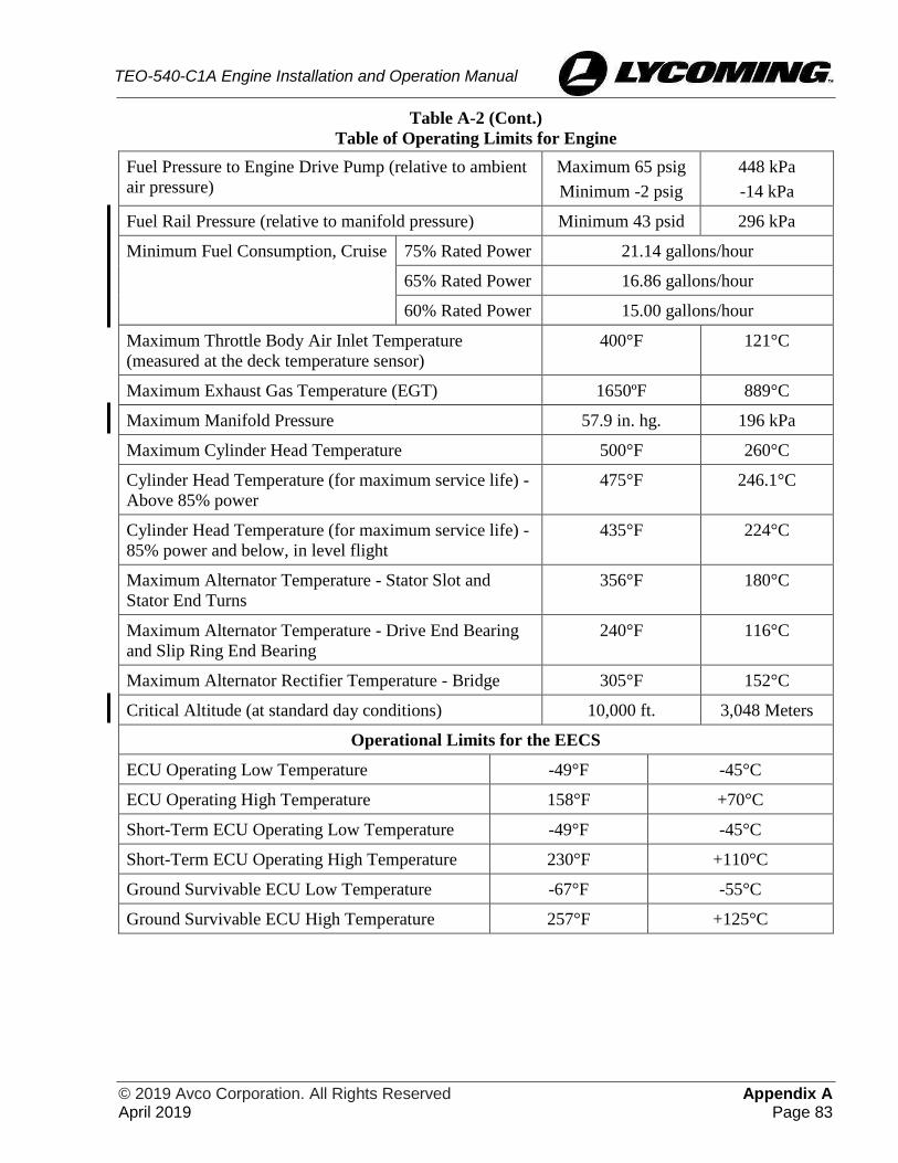
© 2019 Avco Corporation. All Rights Reserved Appendix A April 2019 Page 83
TEO-540-C1A Engine Installation and Operation Manual
Table A-2 (Cont.)
Table of Operating Limits for Engine
Fuel Pressure to Engine Drive Pump (relative to ambient
air pressure)
Maximum 65 psig
Minimum -2 psig
448 kPa
-14 kPa
Fuel Rail Pressure (relative to manifold pressure) Minimum 43 psid 296 kPa
Minimum Fuel Consumption, Cruise 75% Rated Power 21.14 gallons/hour
65% Rated Power 16.86 gallons/hour
60% Rated Power 15.00 gallons/hour
Maximum Throttle Body Air Inlet Temperature
(measured at the deck temperature sensor)
400°F 121°C
Maximum Exhaust Gas Temperature (EGT) 1650ºF 889°C
Maximum Manifold Pressure 57.9 in. hg. 196 kPa
Maximum Cylinder Head Temperature 500°F 260°C
Cylinder Head Temperature (for maximum service life) -
Above 85% power
475°F 246.1°C
Cylinder Head Temperature (for maximum service life) -
85% power and below, in level flight
435°F 224°C
Maximum Alternator Temperature - Stator Slot and
Stator End Turns
356°F 180°C
Maximum Alternator Temperature - Drive End Bearing
and Slip Ring End Bearing
240°F 116°C
Maximum Alternator Rectifier Temperature - Bridge 305°F 152°C
Critical Altitude (at standard day conditions) 10,000 ft. 3,048 Meters
Operational Limits for the EECS
ECU Operating Low Temperature -49°F -45°C
ECU Operating High Temperature 158°F +70°C
Short-Term ECU Operating Low Temperature -49°F -45°C
Short-Term ECU Operating High Temperature 230°F +110°C
Ground Survivable ECU Low Temperature -67°F -55°C
Ground Survivable ECU High Temperature 257°F +125°C

Appendix A © 2019 Avco Corporation. All Rights Reserved Page 84 April 2019
TEO-540-C1A Engine Installation and Operation Manual
Table A-3
Accessory Drives
Accessory Type of Drive Direction of
Rotation
Drive
Ratio
Maximum Torque Maximum
Overhang
Moment Continuous Static
in.-lb Nm in.-lb Nm in.-lb Nm
Starter SAE
Counter-
clockwise 16.556:1 -- -- 450 51 150 17
Alternator SAE Clockwise 3.10:1 60 7 120 14 175 20
Accessory
Pad 1 AND20000*
Counter-
clockwise 1.3:1 70 8 800 90 25 3
Accessory
Pad 2 AND20000** Clockwise 1.385:1 100 11 800 90 40 5
Prop. Gov.
Pad AND20010***
Clockwise
(Viewing Pad) 0.947:1 125 14 2200 249 25 3
Fuel Pump AND20003 Clockwise 1.0:1 25 3 450 51 25 3
Compressor SAE Clockwise 1.462:1**** Limited by belt
* Except for rotation and torque limitations
** Except no provision for oil to accessory
*** Except for torque limitation
**** With compressor pulley diameter of 6.00 inches

© 2019 Avco Corporation. All Rights Reserved Appendix A April 2019 Page 85
TEO-540-C1A Engine Installation and Operation Manual
Figure A-1
Cooling Air Requirements

Appendix A © 2019 Avco Corporation. All Rights Reserved Page 86 April 2019
TEO-540-C1A Engine Installation and Operation Manual
Figure A-2
Propeller Governor Oil Transfer Leakage Rate

© 2019 Avco Corporation. All Rights Reserved Appendix A April 2019 Page 87
TEO-540-C1A Engine Installation and Operation Manual
Figure A-3
2575 RPM Sea Level and Altitude Performance

Appendix A © 2019 Avco Corporation. All Rights Reserved Page 88 April 2019
TEO-540-C1A Engine Installation and Operation Manual
Figure A-4
2400 RPM Sea Level and Altitude Performance
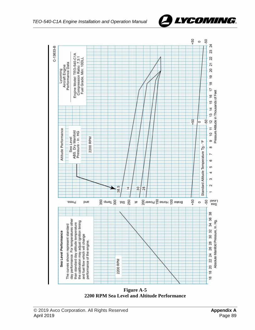
© 2019 Avco Corporation. All Rights Reserved Appendix A April 2019 Page 89
TEO-540-C1A Engine Installation and Operation Manual
Figure A-5
2200 RPM Sea Level and Altitude Performance

Appendix A © 2019 Avco Corporation. All Rights Reserved Page 90 April 2019
TEO-540-C1A Engine Installation and Operation Manual
Figure A-6
Fuel Flow versus Percent of Rated Power

© 2019 Avco Corporation. All Rights Reserved Appendix B April 2019 Page 91
TEO-540-C1A Engine Installation and Operation Manual
APPENDIX B
OPERATING LIMITATIONS
Functional Limitation Requirements
Limitations of the EECS
EEC Physical Environmental Limits
The EECS components (ECU, Power Box, and DLU) have the physical environmental limits shown
in Table B-1.
Table B-1
Physical Environmental Limits
DO-160
Task
No.
Item
Physical Environment Limit
(DO-160F Levels)
EECS Sensor and
Actuators
ECU and
Power Box
4 Temperature and Altitude B3 B3
5 Temperature Variation A A
6 Humidity C C
8 Vibration Engine Durability R Curve I
9 Explosive Atmosphere IIE IIE
10 Waterproofness S S
11 Fluid Susceptibility F F
12 Sand and Dust D D
13 Fungus Resistance F F
14 Salt Fog S S
15 Magnetic Effect N/A N/A
16 Power Input Z Z
17 Voltage Spike A A
18 Audio Frequency Conducted Susceptibility -
Power Inputs
Z Z
19 Induced Signal Susceptibility ZC ZC
20 Radio Frequency Susceptibility (Radiated and
Conducted)
W/D W/D
21 Emissions of Radio Frequency Energy B B
22 Lightning Induced Transient Susceptibility A3G33 A3G33
25 Electrostatic Discharge (ESD) N/A A

Appendix B © 2019 Avco Corporation. All Rights Reserved Page 92 April 2019
TEO-540-C1A Engine Installation and Operation Manual
This page intentionally left blank.

© 2019 Avco Corporation. All Rights Reserved Appendix C April 2019 Page 93
TEO-540-C1A Engine Installation and Operation Manual
APPENDIX C
SAFETY
Table C-1 shows the safety alert messages.
Table C-1.
Safety Alert Messages
Ref. ID Title
1 WARNING Connection of equipment or devices other than the Lycoming “Field
Service Tool” to CAN 2 Bus may compromise safe EECS operation.
Connection of non-Lycoming approved equipment or devices to the
CAN 2 bus interface is prohibited. The Field Service Tool must not
be used in flight.
2 WARNING In the event of a NTO indication in flight, the operator should make
minimum and gentle throttle changes to reduce operability anomalies.
3 WARNING After a software installation, the maintainer shall confirm proper and
correct software loading via the Lycoming Field Service Tool.
4 WARNING An ECU reset (re-initialization) shall only be conducted as a last
chance recovery attempt from an EECS anomaly as determined
necessary by the operator. It is possible that an ECU reset may not be
recoverable. The operator must take this into consideration when
deciding to command a reset.
5 WARNING The NTO indication provides an indication that the ECU along with
limited conventional engine hardware is acceptably safe for flight
once a proper PFT is conducted. The operator must still interrogate
conventional engine indications to determine that the conventional
engine is also acceptable safe for flight.
6 WARNING The operator must properly conduct a PFT prior to flight.
7 WARNING The operator must allow sufficient time for the PFT to be completely
executed (as indicated by the PFT active annunciator) prior to making
any throttle changes otherwise the PFT may be inadvertently
canceled with no other indication that the PFT is incomplete.
8 CAUTION The PFT is not to be commanded during flight. If the PFT is
commanded during flight, throttle movement will cancel the PFT.
9 CAUTION To ensure proper EECS operation, the Lycoming Field Service Tool
shall not be used during flight.
10 CAUTION Selection of the IGNITION ON-OFF switch to OFF during ground
operations is a single interlock. To ensure that the engine is not
inadvertently started or the ignition system is not inadvertently
actuated during maintenance, electrical power should be removed
from the ECU during maintenance as a secondary interlock to prevent
injury.

Appendix C © 2019 Avco Corporation. All Rights Reserved Page 94 April 2019
TEO-540-C1A Engine Installation and Operation Manual
This page intentionally left blank.

© 2019 Avco Corporation. All Rights Reserved Appendix D April 2019 Page 95
TEO-540-C1A Engine Installation and Operation Manual
APPENDIX D
WIRING DIAGRAMS
NOTICE: For Wiring Harness Leads and Connection Location, Airframe Wiring Interface,
Communications Buses, Volt Power System Connection, System Wiring Diagrams, and
Communications Bus Data refer to Appendix B in the TEO-540-C1A Engine
Maintenance Manual.

Appendix D © 2019 Avco Corporation. All Rights Reserved Page 96 April 2019
TEO-540-C1A Engine Installation and Operation Manual
This page intentionally left blank.