
ENGINE EMISSION CONTROL - Terios Club Italia · ENGINE EMISSION CONTROL ... Connect the DS-II to...
15
EC ENGINE EMISSION CONTROL EMISSION CONTROL SYSTEM (3SZ-VE) OPERATION CHECK . . . . . . . . . . . . . . . . . . . . . . . . . . . . . . . . . . . . . . . . . EC-1 LOCATION . . . . . . . . . . . . . . . . . . . . . . . . . . . . . . . . . . . . . . . . . . . . . . . . . . EC-3 EMISSION CONTROL SYSTEM (K3-VE) OPERATION CHECK . . . . . . . . . . . . . . . . . . . . . . . . . . . . . . . . . . . . . . . . . EC-4 LOCATION . . . . . . . . . . . . . . . . . . . . . . . . . . . . . . . . . . . . . . . . . . . . . . . . . . EC-6 OXYGEN SENSOR (3SZ-VE) COMPONENTS . . . . . . . . . . . . . . . . . . . . . . . . . . . . . . . . . . . . . . . . . . . . . . EC-7 REMOVAL . . . . . . . . . . . . . . . . . . . . . . . . . . . . . . . . . . . . . . . . . . . . . . . . . . EC-8 INSTALLATION . . . . . . . . . . . . . . . . . . . . . . . . . . . . . . . . . . . . . . . . . . . . . . EC-8 INSPECTION . . . . . . . . . . . . . . . . . . . . . . . . . . . . . . . . . . . . . . . . . . . . . . . . EC-8 OXYGEN SENSOR (K3-VE) COMPONENTS . . . . . . . . . . . . . . . . . . . . . . . . . . . . . . . . . . . . . . . . . . . . . . EC-9 REMOVAL . . . . . . . . . . . . . . . . . . . . . . . . . . . . . . . . . . . . . . . . . . . . . . . . . . EC-10 INSTALLATION . . . . . . . . . . . . . . . . . . . . . . . . . . . . . . . . . . . . . . . . . . . . . . EC-10 INSPECTION . . . . . . . . . . . . . . . . . . . . . . . . . . . . . . . . . . . . . . . . . . . . . . . . EC-10 OXYGEN SENSOR NO. 2 (3SZ-VE) COMPONENTS . . . . . . . . . . . . . . . . . . . . . . . . . . . . . . . . . . . . . . . . . . . . . . EC-11 REMOVAL . . . . . . . . . . . . . . . . . . . . . . . . . . . . . . . . . . . . . . . . . . . . . . . . . . EC-12 INSTALLATION . . . . . . . . . . . . . . . . . . . . . . . . . . . . . . . . . . . . . . . . . . . . . . EC-12 OXYGEN SENSOR NO. 2 (K3-VE) COMPONENTS . . . . . . . . . . . . . . . . . . . . . . . . . . . . . . . . . . . . . . . . . . . . . . EC-13 REMOVAL . . . . . . . . . . . . . . . . . . . . . . . . . . . . . . . . . . . . . . . . . . . . . . . . . . EC-14 INSTALLATION . . . . . . . . . . . . . . . . . . . . . . . . . . . . . . . . . . . . . . . . . . . . . . EC-14 TO INDEX
-
Upload
truongthuan -
Category
Documents
-
view
249 -
download
15
Transcript of ENGINE EMISSION CONTROL - Terios Club Italia · ENGINE EMISSION CONTROL ... Connect the DS-II to...

EC
ENGINE
EMISSION CONTROL
EMISSION CONTROL SYSTEM (3SZ-VE)OPERATION CHECK . . . . . . . . . . . . . . . . . . . . . . . . . . . . . . . . . . . . . . . . . EC-1LOCATION. . . . . . . . . . . . . . . . . . . . . . . . . . . . . . . . . . . . . . . . . . . . . . . . . . EC-3
EMISSION CONTROL SYSTEM (K3-VE)OPERATION CHECK . . . . . . . . . . . . . . . . . . . . . . . . . . . . . . . . . . . . . . . . . EC-4LOCATION. . . . . . . . . . . . . . . . . . . . . . . . . . . . . . . . . . . . . . . . . . . . . . . . . . EC-6
OXYGEN SENSOR (3SZ-VE)COMPONENTS . . . . . . . . . . . . . . . . . . . . . . . . . . . . . . . . . . . . . . . . . . . . . . EC-7REMOVAL . . . . . . . . . . . . . . . . . . . . . . . . . . . . . . . . . . . . . . . . . . . . . . . . . . EC-8INSTALLATION . . . . . . . . . . . . . . . . . . . . . . . . . . . . . . . . . . . . . . . . . . . . . . EC-8INSPECTION . . . . . . . . . . . . . . . . . . . . . . . . . . . . . . . . . . . . . . . . . . . . . . . . EC-8
OXYGEN SENSOR (K3-VE)COMPONENTS . . . . . . . . . . . . . . . . . . . . . . . . . . . . . . . . . . . . . . . . . . . . . . EC-9REMOVAL . . . . . . . . . . . . . . . . . . . . . . . . . . . . . . . . . . . . . . . . . . . . . . . . . . EC-10INSTALLATION . . . . . . . . . . . . . . . . . . . . . . . . . . . . . . . . . . . . . . . . . . . . . . EC-10INSPECTION . . . . . . . . . . . . . . . . . . . . . . . . . . . . . . . . . . . . . . . . . . . . . . . . EC-10
OXYGEN SENSOR NO. 2 (3SZ-VE)COMPONENTS . . . . . . . . . . . . . . . . . . . . . . . . . . . . . . . . . . . . . . . . . . . . . . EC-11REMOVAL . . . . . . . . . . . . . . . . . . . . . . . . . . . . . . . . . . . . . . . . . . . . . . . . . . EC-12INSTALLATION . . . . . . . . . . . . . . . . . . . . . . . . . . . . . . . . . . . . . . . . . . . . . . EC-12
OXYGEN SENSOR NO. 2 (K3-VE)COMPONENTS . . . . . . . . . . . . . . . . . . . . . . . . . . . . . . . . . . . . . . . . . . . . . . EC-13REMOVAL . . . . . . . . . . . . . . . . . . . . . . . . . . . . . . . . . . . . . . . . . . . . . . . . . . EC-14INSTALLATION . . . . . . . . . . . . . . . . . . . . . . . . . . . . . . . . . . . . . . . . . . . . . . EC-14
TO INDEX

EC–1 EMISSION CONTROL - EMISSION CONTROL SYSTEM (3SZ-VE)
EC
ENGINEEMISSION CONTROLEMISSION CONTROL SYSTEM (3SZ-VE)OPERATION CHECK1. AIR FUEL RATIO COMPENSATION DEVICE
(a) Connect the DS-II to the DLC.(b) Select the following items following the prompts on the DS-II
screen: DATA LIST / FrO2 SENSOR OUTPUT VOLTAGE /RrO2 SENSOR OUTPUT VOLTAGE . Then check that the volt-age changes.(1) Maintain the engine speed at 2,500 r/min for about 2 min-
utes to warm up the oxygen sensor.(2) Keeping the engine speed at 2,500 r/min, check that the
DS-II indicates that the voltage alternates between 0 Vand 1 V.Standard:
The voltage changes 8 times or more in 10 seconds.NOTICE:• Perform immediately after oxygen sensor warm-up
in order to ensure that the sensor does not cooldown.
• If the tester does not indicate voltage changes,warm up the oxygen sensor again before perform-ing this inspection.
2. DECELERATION CONTROL DEVICE(a) Set the engine speed to about 3,500 r/min.(b) Using a sound scope, check the operating sound of the injector.(c) Check that the operating sound of the injector stops momen-
tarily and then resumes once again when the accelerator pedalis released.
3. FUEL EVAPORATIVE GAS SUPPRESSION DEVICE(a) Connect the DS-II to the DLC.
(b) After starting the engine, disconnect fuel vapor feed hose No. 1as shown in the illustration.
(c) Following the prompts on the DS-II screen, select the followingitems: ACTIVE TEST / PURGE VSV. Then, with the VSV set toON, check that a vacuum occurs at the VSV port.
(d) If the check result is abnormal, check the following items.(1) VSV (for evap purge)(2) Clogging in the fuel vapor feed hose No. 2 (between the
throttle body and VSV)(3) Engine control computer PRG voltage
(e) Exit ACTIVE TEST and restore the fuel vapor feed hose No. 1.(f) Following the prompts on the DS-II screen, display the DATA
LIST screen. Then select EVAP PURGE OUTPUT in order tocheck the purge VSV operation.
(g) After sufficiently warming up the vehicle, check that the value ofthe data list is 0% when at idle speed.
A136713

EMISSION CONTROL - EMISSION CONTROL SYSTEM (3SZ-VE) EC–2
EC
4. VISUAL INSPECTION(a) Check that there are no cracks, leaks, or damage.
HINT:• Removing the oil level gauge, oil filler cap, or PCV hose may
cause the engine to run improperly or stall.• If the parts between the throttle body and the cylinder head
are dislocated, loosened, or cracked, secondary air will besucked in and the engine may run improperly or stall.
5. CHECK CHARCOAL CANISTER ASSEMBLY(a) Using a MIGHTY VAC, perform a check following the inspection
procedures.(1) With the air port covered tightly (by pressing down with a
finger), apply positive pressure to the tank port.Standard:
There is air-flow between the tank port and thepurge port.
(2) With the air port covered tightly (by pressing down with afinger), apply negative pressure to the tank port.Standard:
There is air-flow between the tank port and thepurge port.
A109297
Purge Port
Atmosphere Port
Tank Port
A139376J01

EC–3 EMISSION CONTROL - EMISSION CONTROL SYSTEM (3SZ-VE)
EC
LOCATION
OXYGEN SENSOR
OXYGEN SENSOR NO. 2
A137726J01

EMISSION CONTROL - EMISSION CONTROL SYSTEM (K3-VE) EC–4
EC
ENGINEEMISSION CONTROLEMISSION CONTROL SYSTEM (K3-VE)OPERATION CHECK1. AIR FUEL RATIO COMPENSATION DEVICE
(a) Connect the DS-II to the DLC.(b) Select the following items following the prompts on the DS-II
screen: ECU DATA MONITOR / FrO2 SENSOR OUTPUT VOLTAGE / RrO2 SENSOR OUTPUT VOLTAGE. Then check that the voltage changes.(1) Maintain the engine speed at 2,500 r/min for about 2 min-
utes to warm up the oxygen sensor.(2) Keeping the engine speed at 2,500 r/min, check that the
DS-II indicates that the voltage alternates between 0 Vand 1 V.Standard:
The voltage changes 8 times or more in 10 seconds.NOTICE:• Perform immediately after oxygen sensor warm-up
in order to ensure that the sensor does not cooldown.
• If the tester does not indicate the changes of volt-age, warm up the oxygen sensor again before per-forming this inspection.
2. DECELERATION CONTROL DEVICE(a) Set the engine speed to about 3,500 r/min.(b) Using a sound scope, check the operating sound of the injector.(c) Check that the operating sound of the injector stops momen-
tarily and then resumes once again when the accelerator pedalis released.
3. FUEL EVAPORATIVE GAS SUPPRESSION DEVICE(a) Connect the DS-II to the DLC.
(b) After starting the engine, disconnect the fuel vapor feed hoseNo. 1 shown in the illustration.
(c) Following the prompts on the DS-II screen, select the followingitems: ACTIVE TEST / PURGE VSV. Then, with the VSV set toON, check that a vacuum occurs at the VSV port.
(d) If the check result is abnormal, check the following items.(1) VSV (for evap purge)(2) Clogging in the fuel vapor feed hose No. 2 (between the
throttle body and VSV)(3) Engine control computer PRG voltage
(e) Exit ACTIVE TEST and restore the fuel vapor feed hose No. 1.(f) Following the prompts on the DS-II screen, display the DATA
LIST screen. Then select EVAP PURGE OUTPUT in order tocheck the purge VSV operation.
(g) After sufficiently warming up the vehicle, check that the value ofthe data list is 0% when at idle speed.
A136713

EC–5 EMISSION CONTROL - EMISSION CONTROL SYSTEM (K3-VE)
EC
4. VISUAL INSPECTION(a) Check that there are no cracks, leaks, or damage.
HINT:• Removing the oil level gauge, oil filler cap, or PCV hose may
cause the engine to run improperly or stall.• If the parts between the throttle body and the cylinder head
are dislocated, loosened, or cracked, secondary air will besucked in and the engine may run improperly or stall.
5. CHECK CHARCOAL CANISTER ASSEMBLY(a) Using a MIGHTY VAC, perform a check following the inspection
procedures.(1) With the air port covered tightly (by pressing down with a
finger), apply positive pressure to the tank port.Standard:
There is air-flow between the tank port and thepurge port.
(2) With the air port covered tightly (by pressing down with afinger), apply negative pressure to the tank port.Standard:
There is air-flow between the tank port and thepurge port.
A109297
Purge Port
Atmosphere Port
Tank Port
A139376J01

EMISSION CONTROL - EMISSION CONTROL SYSTEM (K3-VE) EC–6
EC
LOCATION
OXYGEN SENSOR
OXYGEN SENSOR NO. 2
A137726J01

EC–7 EMISSION CONTROL - OXYGEN SENSOR (3SZ-VE)
EC
ENGINEEMISSION CONTROLOXYGEN SENSOR (3SZ-VE)COMPONENTS
T=34{367}
OXYGEN SENSOR
TIGHTENING TORQUE A135991J01
EMISSION CONTROL - OXYGEN SENSOR (3SZ-VE) EC–8
EC
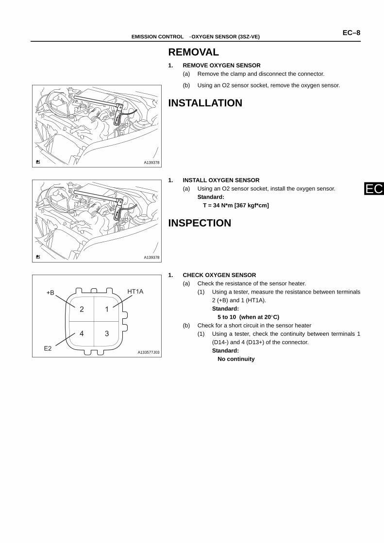
REMOVAL1. REMOVE OXYGEN SENSOR
(a) Remove the clamp and disconnect the connector.
(b) Using an O2 sensor socket, remove the oxygen sensor.
INSTALLATION
1. INSTALL OXYGEN SENSOR(a) Using an O2 sensor socket, install the oxygen sensor.
Standard:T = 34 N*m [367 kgf*cm]
INSPECTION
1. CHECK OXYGEN SENSOR(a) Check the resistance of the sensor heater.
(1) Using a tester, measure the resistance between terminals2 (+B) and 1 (HT1A).Standard:
5 to 10 (when at 20°C)(b) Check for a short circuit in the sensor heater
(1) Using a tester, check the continuity between terminals 1(D14-) and 4 (D13+) of the connector.Standard:
No continuity
A139378
A139378
12
34
+B
E2
HT1A
A133577J03

EC–9 EMISSION CONTROL - OXYGEN SENSOR (K3-VE)
EC
ENGINEEMISSION CONTROLOXYGEN SENSOR (K3-VE)COMPONENTS
T=34{367}
OXYGEN SENSOR
TIGHTENING TORQUE A135991J01

EMISSION CONTROL - OXYGEN SENSOR (K3-VE) EC–10
EC
REMOVAL1. REMOVE OXYGEN SENSOR
(a) Remove the clamp and disconnect the connector.
(b) Using an O2 sensor socket, remove the oxygen sensor.
INSTALLATION
1. INSTALL OXYGEN SENSOR(a) Using an O2 sensor socket, install the oxygen sensor.
Standard:T = 34 N*m [367 kgf*cm]
INSPECTION
1. CHECK OXYGEN SENSOR(a) Check the resistance of the sensor heater.
(1) Using a tester, measure the resistance between terminals2 (+B) and 1 (HT1A).Standard:
5 to 10 (when at 20°C)(b) Check for a short circuit in the sensor heater
(1) Using a tester, check the continuity between terminals 1(D14-) and 4 (D13+) of the connector.Standard:
No continuity
A139378
A139378
12
34
+B
E2
HT1A
A133577J03

EC–11 EMISSION CONTROL - OXYGEN SENSOR NO. 2 (3SZ-VE)
EC
ENGINEEMISSION CONTROLOXYGEN SENSOR NO. 2 (3SZ-VE)COMPONENTS
T=5.4{55}
T=34{367
×6
Oxygen Sensor NO. 2
Engine Under Cover RR LH
Tightening Torque A135989J02
EMISSION CONTROL - OXYGEN SENSOR NO. 2 (3SZ-VE) EC–12
EC
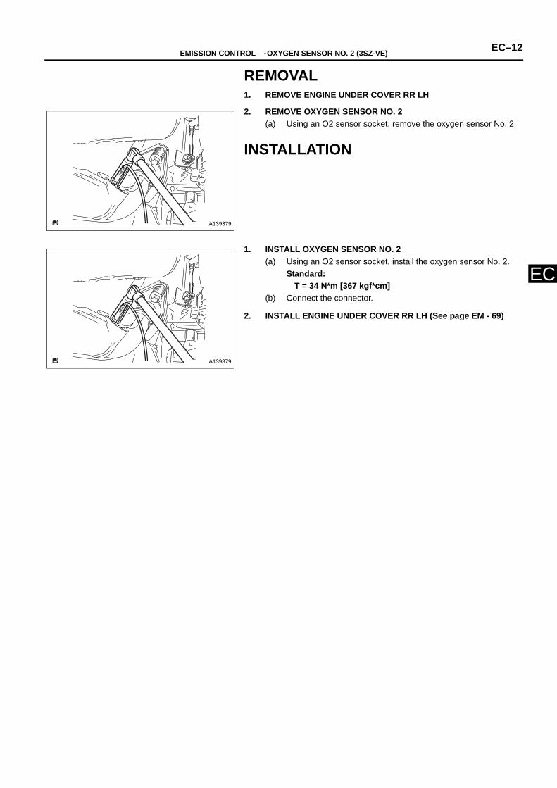
REMOVAL1. REMOVE ENGINE UNDER COVER RR LH
2. REMOVE OXYGEN SENSOR NO. 2(a) Using an O2 sensor socket, remove the oxygen sensor No. 2.
INSTALLATION
1. INSTALL OXYGEN SENSOR NO. 2(a) Using an O2 sensor socket, install the oxygen sensor No. 2.
Standard:T = 34 N*m [367 kgf*cm]
(b) Connect the connector.
2. INSTALL ENGINE UNDER COVER RR LH (See page EM - 69)
A139379
A139379

EC–13 EMISSION CONTROL - OXYGEN SENSOR NO. 2 (K3-VE)
EC
ENGINEEMISSION CONTROLOXYGEN SENSOR NO. 2 (K3-VE)COMPONENTS
T=5.4{55}
T=34{367
×6
Oxygen Sensor NO. 2
Engine Under Cover RR LH
Tightening Torque A135989J02

EMISSION CONTROL - OXYGEN SENSOR NO. 2 (K3-VE) EC–14
EC
REMOVAL1. REMOVE ENGINE UNDER COVER RR LH
2. REMOVE OXYGEN SENSOR NO. 2(a) Using an O2 sensor socket, remove the oxygen sensor No. 2.
INSTALLATION
1. INSTALL OXYGEN SENSOR NO. 2(a) Using an O2 sensor socket, install the oxygen sensor No. 2.
Standard:T = 34 N*m [367 kgf*cm]
(b) Connect the connector.
2. INSTALL ENGINE UNDER COVER RR LH (See page EM - 104)
A139379
A139379
TO INDEX TO NEXT SECTION


![EMISSION SYSTEM LOCATION INDEX [LF] - mellens.net · 2007 ENGINE PERFORMANCE Emission System - MX-5 Miata EMISSION SYSTEM LOCATION INDEX [LF] ENGINE COMPARTMENT SIDE Fig. 1: Identifying](https://static.fdocuments.us/doc/165x107/5b583af77f8b9a527f8be4ff/emission-system-location-index-lf-2007-engine-performance-emission-system.jpg)


