ENGINE ECR A
331
ECR-1 ENGINE C D E F G H I J K L M SECTION ECR A ECR N O P CONTENTS ENGINE CONTROL SYSTEM (M9R) M9R BASIC INSPECTION ................................... 7 DIAGNOSIS AND REPAIR WORKFLOW ......... 7 Work Flow ................................................................ 7 Diagnostic Work Sheet ............................................. 9 INSPECTION AND ADJUSTMENT ...................11 BASIC INSPECTION ................................................ 11 BASIC INSPECTION : Special Repair Require- ment ....................................................................... 11 ADDITIONAL SERVICE WHEN REPLACING CONTROL UNIT ....................................................... 12 ADDITIONAL SERVICE WHEN REPLACING CONTROL UNIT : Description ............................... 12 ADDITIONAL SERVICE WHEN REPLACING CONTROL UNIT : Special Repair Requirement .... 12 IDLE SPEED ............................................................. 13 IDLE SPEED : Description ..................................... 13 IDLE SPEED : Special Repair Requirement .......... 13 ZFC VALUE RESET ................................................. 13 ZFC VALUE RESET : Description ......................... 13 ZFC VALUE RESET : Special Repair Require- ment ....................................................................... 14 INJECTOR ADJUSTMENT VALUE REGISTRA- TION .......................................................................... 14 INJECTOR ADJUSTMENT VALUE REGISTRA- TION : Description .................................................. 14 INJECTOR ADJUSTMENT VALUE REGISTRA- TION : Special Repair Requirement ....................... 14 EGR VOLUME CONTROL VALVE CLOSED POSI- TION LEARNING VALUE CLEAR ........................... 15 EGR VOLUME CONTROL VALVE CLOSED PO- SITION LEARNING VALUE CLEAR : Description .... 15 EGR VOLUME CONTROL VALVE CLOSED PO- SITION LEARNING VALUE CLEAR : Special Re- pair Requirement ....................................................15 EGR VOLUME CONTROL VALVE CLOSED POSI- TION LEARNING ......................................................15 EGR VOLUME CONTROL VALVE CLOSED PO- SITION LEARNING : Description ...........................15 EGR VOLUME CONTROL VALVE CLOSED PO- SITION LEARNING : Special Repair Requirement ....15 THROTTLE VALVE CLOSED POSITION LEARN- ING VALUE CLEAR ..................................................16 THROTTLE VALVE CLOSED POSITION LEARNING VALUE CLEAR : Description ..............16 THROTTLE VALVE CLOSED POSITION LEARNING VALUE CLEAR : Special Repair Re- quirement ................................................................16 THROTTLE VALVE CLOSED POSITION LEARN- ING ............................................................................16 THROTTLE VALVE CLOSED POSITION LEARNING : Description ........................................16 THROTTLE VALVE CLOSED POSITION LEARNING : Special Repair Requirement .............16 SERVICE REGENERATION .....................................16 SERVICE REGENERATION : Description .............16 SERVICE REGENERATION : Special Repair Re- quirement ................................................................17 DPF DATA CLEAR ...................................................17 DPF DATA CLEAR : Description ............................17 DPF DATA CLEAR : Special Repair Requirement ....17 AIR FUEL RATIO SENSOR LEARNING VALUE CLEAR ......................................................................17 AIR FUEL RATIO SENSOR LEARNING VALUE CLEAR : Description ...............................................17 AIR FUEL RATIO SENSOR LEARNING VALUE CLEAR : Special Repair Requirement .................
Transcript of ENGINE ECR A

ENGINE
C
D
E
SECTION ECRA
ECR
ENGINE CONTROL SYSTEM (M9R)
F
G
H
I
J
K
L
M
N
O
P
CONTENTS
M9R
BASIC INSPECTION .................................... 7
DIAGNOSIS AND REPAIR WORKFLOW .......... 7Work Flow .................................................................7Diagnostic Work Sheet ..............................................9
INSPECTION AND ADJUSTMENT ....................11
BASIC INSPECTION .................................................11BASIC INSPECTION : Special Repair Require-ment ........................................................................11
ADDITIONAL SERVICE WHEN REPLACING CONTROL UNIT ........................................................12
ADDITIONAL SERVICE WHEN REPLACING CONTROL UNIT : Description ................................12ADDITIONAL SERVICE WHEN REPLACING CONTROL UNIT : Special Repair Requirement .....12
IDLE SPEED ..............................................................13IDLE SPEED : Description ......................................13IDLE SPEED : Special Repair Requirement ...........13
ZFC VALUE RESET ..................................................13ZFC VALUE RESET : Description ..........................13ZFC VALUE RESET : Special Repair Require-ment ........................................................................14
INJECTOR ADJUSTMENT VALUE REGISTRA-TION ...........................................................................14
INJECTOR ADJUSTMENT VALUE REGISTRA-TION : Description ...................................................14INJECTOR ADJUSTMENT VALUE REGISTRA-TION : Special Repair Requirement ........................14
EGR VOLUME CONTROL VALVE CLOSED POSI-TION LEARNING VALUE CLEAR ............................15
EGR VOLUME CONTROL VALVE CLOSED PO-SITION LEARNING VALUE CLEAR : Description ....15
EGR VOLUME CONTROL VALVE CLOSED PO-SITION LEARNING VALUE CLEAR : Special Re-pair Requirement .....................................................15
EGR VOLUME CONTROL VALVE CLOSED POSI-TION LEARNING .......................................................15
EGR VOLUME CONTROL VALVE CLOSED PO-SITION LEARNING : Description ............................15EGR VOLUME CONTROL VALVE CLOSED PO-SITION LEARNING : Special Repair Requirement
....15
THROTTLE VALVE CLOSED POSITION LEARN-ING VALUE CLEAR ...................................................16
THROTTLE VALVE CLOSED POSITION LEARNING VALUE CLEAR : Description ...............16THROTTLE VALVE CLOSED POSITION LEARNING VALUE CLEAR : Special Repair Re-quirement .................................................................16
THROTTLE VALVE CLOSED POSITION LEARN-ING .............................................................................16
THROTTLE VALVE CLOSED POSITION LEARNING : Description .........................................16THROTTLE VALVE CLOSED POSITION LEARNING : Special Repair Requirement ..............16
SERVICE REGENERATION ......................................16SERVICE REGENERATION : Description ..............16SERVICE REGENERATION : Special Repair Re-quirement .................................................................17
DPF DATA CLEAR ....................................................17DPF DATA CLEAR : Description .............................17DPF DATA CLEAR : Special Repair Requirement ....17
AIR FUEL RATIO SENSOR LEARNING VALUE CLEAR .......................................................................17
AIR FUEL RATIO SENSOR LEARNING VALUE CLEAR : Description ................................................17AIR FUEL RATIO SENSOR LEARNING VALUE CLEAR : Special Repair Requirement .................
ECR-1

FUNCTION DIAGNOSIS ............................. 19
ENGINE CONTROL SYSTEM ........................... 19System Diagram ..................................................... 19System Description ................................................. 20Component Parts Location ..................................... 20Component Description .......................................... 24
FUEL INJECTION CONTROL ........................... 25System Description ................................................. 25Component Parts Location ..................................... 30Component Description .......................................... 34
FUEL INJECTION TIMING CONTROL SYS-TEM .................................................................... 35
System Diagram ..................................................... 35System Description ................................................. 35Component Parts Location ..................................... 36Component Description .......................................... 40
AUTOMATIC SPEED CONTROL DEVICE (ASCD) ............................................................... 41
System Diagram ..................................................... 41System Description ................................................. 41Component Parts Location ..................................... 43Component Description ......................................... 47
CAN COMMUNICATION ................................... 48System Description ................................................. 48
COOLING FAN CONTROL ............................... 49System Diagram ..................................................... 49System Description ................................................. 49Component Parts Location ..................................... 51Component Description .......................................... 55
DPF .................................................................... 56System Diagram ..................................................... 56System Description ................................................. 57Component Parts Location ..................................... 59Component Description .......................................... 63
EGR SYSTEM .................................................... 64System Description ................................................. 64Component Parts Location ..................................... 66Component Description .......................................... 70
ENGINE TORQUE CONTROL .......................... 71System Diagram ..................................................... 71System Description ................................................. 71Component Parts Location ..................................... 72Component Description .......................................... 76
GLOW CONTROL ............................................. 77System Diagram ..................................................... 77System Description ................................................. 77Component Parts Location ..................................... 78Component Description .......................................... 82
IDLE SPEED CONTROL ................................... 83System Diagram ..................................................... 83
System Description ................................................. 83Component Parts Location ..................................... 84Component Description .......................................... 88
TURBOCHARGER BOOST CONTROL ............ 89System Description ................................................. 89Component Parts Location ..................................... 92Component Description .......................................... 96
ON BOARD DIAGNOSTIC (OBD) SYSTEM ..... 97Diagnosis Description ............................................. 97CONSULT-III Function .......................................... 101Diagnosis Tool Function ...................................... 108
COMPONENT DIAGNOSIS ......................111
POWER SUPPLY AND GROUND CIRCUIT ....111Diagnosis Procedure ............................................. 111
U1000 CAN COMM CIRCUIT ...........................114Description ............................................................ 114DTC Logic ............................................................. 114Diagnosis Procedure ............................................. 114
P0016 CKP - CMP CORRELATION .................115DTC Logic ............................................................. 115Diagnosis Procedure ............................................. 115
P0045 TC BOOST CONTROL SOLENOID VALVE ..............................................................117
Description ............................................................ 117DTC Logic ............................................................. 117Diagnosis Procedure ............................................. 117Component Inspection .......................................... 118
P0089 FUEL PUMP ..........................................119DTC Logic ............................................................. 119Diagnosis Procedure ............................................. 119Component Inspection .......................................... 120
P0090 FUEL PUMP ..........................................121DTC Logic ............................................................. 121Diagnosis Procedure ............................................. 121Component Inspection .......................................... 122
P0100 MAF SENSOR .......................................123Description ............................................................ 123DTC Logic ............................................................. 123Diagnosis Procedure ............................................. 123Component Inspection .......................................... 125
P0101 MAF SENSOR .......................................126Description ............................................................ 126DTC Logic ............................................................. 126Diagnosis Procedure ............................................. 127Component Inspection .......................................... 128
P0110 IAT SENSOR .........................................130Description ............................................................ 130DTC Logic ............................................................. 130Diagnosis Procedure ............................................. 130Component Inspection .......................................... 131
ECR-2

C
D
E
F
G
H
I
J
K
L
M
CR
A
N
O
P
E
P0115 ECT SENSOR ....................................... 132Description ............................................................ 132DTC Logic ............................................................. 132Diagnosis Procedure ............................................. 132Component Inspection .......................................... 133
P0120 TP SENSOR .......................................... 134Description ............................................................ 134DTC Logic ............................................................. 134Diagnosis Procedure ............................................. 134Component Inspection .......................................... 135
P0130 A/F SENSOR 1 ...................................... 137Description ............................................................ 137DTC Logic ............................................................. 137Diagnosis Procedure ............................................. 137
P0131 A/F SENSOR 1 ...................................... 139Description ............................................................ 139DTC Logic ............................................................. 139Diagnosis Procedure ............................................. 139
P0133 A/F SENSOR 1 ...................................... 141Description ............................................................ 141DTC Logic ............................................................. 141Diagnosis Procedure ............................................. 141
P0134 A/F SENSOR 1 ...................................... 143Description ............................................................ 143DTC Logic ............................................................. 143Diagnosis Procedure ............................................. 143
P0135 A/F SENSOR 1 HEATER ...................... 145Description ............................................................ 145DTC Logic ............................................................. 145Diagnosis Procedure ............................................. 145Component Inspection .......................................... 147
P0180 FUEL TEMPERATURE SENSOR ......... 148Description ............................................................ 148DTC Logic ............................................................. 148Diagnosis Procedure ............................................. 148Component Inspection .......................................... 149
P0190 FRP SENSOR ....................................... 150Description ............................................................ 150DTC Logic ............................................................. 150Diagnosis Procedure ............................................. 150Component Inspection .......................................... 151
P0200 FUEL INJECTOR .................................. 153DTC Logic ............................................................. 153Diagnosis Procedure ............................................. 153
P0201, P0202, P0203, P0204 FUEL INJEC-TOR .................................................................. 155
Description ............................................................ 155DTC Logic ............................................................. 155Diagnosis Procedure ............................................. 155Component Inspection .......................................... 156
P0225 APP SENSOR ...................................... 158Description .............................................................158DTC Logic ..............................................................158Diagnosis Procedure .............................................158Component Inspection ...........................................160
P0235 TC BOOST SENSOR ........................... 161Description .............................................................161DTC Logic ..............................................................161Diagnosis Procedure .............................................161
P0263, P0266, P0269, P0272 FUEL INJEC-TOR ................................................................. 163
Description .............................................................163DTC Logic ..............................................................163Diagnosis Procedure .............................................163
P0297 SERVICE REGENERATION ................ 164Description .............................................................164DTC Logic ..............................................................164Diagnosis Procedure .............................................164
P0300, P0301, P0302, P0303, P0304 MIS-FIRE ................................................................. 165
DTC Logic ..............................................................165Diagnosis Procedure .............................................165
P0335 CKP SENSOR ...................................... 167Description .............................................................167DTC Logic ..............................................................167Diagnosis Procedure .............................................167Component Inspection ...........................................168
P0340 CMP SENSOR ..................................... 169Description .............................................................169DTC Logic ..............................................................169Diagnosis Procedure .............................................169Component Inspection ...........................................171
P0380 GLOW CONTROL SYSTEM ................ 172DTC Logic ..............................................................172Diagnosis Procedure .............................................172Component Inspection ...........................................174
P0409 EGR VOLUME CONTROL VALVE CONTROL POSITION SENSOR ..................... 175
Description .............................................................175DTC Logic ..............................................................175Diagnosis Procedure .............................................175Component Inspection ...........................................176
P0470 EXHAUST GAS PRESSURE SENSOR . 178Description .............................................................178DTC Logic ..............................................................178Diagnosis Procedure .............................................178
P0487 EGR VOLUME CONTROL VALVE ..... 180Description .............................................................180DTC Logic ..............................................................180Diagnosis Procedure .............................................180Component Inspection ...........................................181
ECR-3

P0488 EGR SYSTEM ...................................... 182DTC Logic ..............................................................182Diagnosis Procedure .............................................182
P0500 VSS ....................................................... 184Description .............................................................184DTC Logic ..............................................................184Diagnosis Procedure .............................................184
P0530 REFRIGERANT PRESSURE SENSOR . 185
Description .............................................................185DTC Logic ..............................................................185Diagnosis Procedure .............................................185
P0544 EGT SENSOR 1 ................................... 187Description .............................................................187DTC Logic ..............................................................187Diagnosis Procedure .............................................187
P0560 BATTERY VOLTAGE ........................... 189DTC Logic ..............................................................189Diagnosis Procedure .............................................189
P0564 ASCD STEERING SWITCH ................. 192Description .............................................................192DTC Logic ..............................................................192Diagnosis Procedure .............................................192Component Inspection ...........................................194
P0571 BPP SWITCH ....................................... 195Description .............................................................195DTC Logic ..............................................................195Diagnosis Procedure .............................................195Component Inspection ...........................................197
P0575 ASCD STEERING SWITCH ................. 198Description .............................................................198DTC Logic ..............................................................198Diagnosis Procedure .............................................198Component Inspection ...........................................199
P0606 ECM ...................................................... 201Description .............................................................201DTC Logic ..............................................................201Diagnosis Procedure .............................................201
P060B ECM ..................................................... 203Description .............................................................203DTC Logic ..............................................................203Diagnosis Procedure .............................................203
P0611 INJECTOR ADJUSTMENT VALUE ..... 205Description .............................................................205DTC Logic ..............................................................205Diagnosis Procedure .............................................205
P062B ECM ..................................................... 207Description .............................................................207DTC Logic ..............................................................207Diagnosis Procedure .............................................207
P062F ECM .......................................................209Description ............................................................ 209DTC Logic ............................................................. 209Diagnosis Procedure ............................................. 209
P0641 SENSOR POWER SUPPLY ..................211DTC Logic ............................................................. 211Diagnosis Procedure ............................................. 211
P0651 SENSOR POWER SUPPLY ..................213DTC Logic ............................................................. 213Diagnosis Procedure ............................................. 213
P0670 GLOW CONTROL SYSTEM .................216DTC Logic ............................................................. 216Diagnosis Procedure ............................................. 216Component Inspection .......................................... 217
P0685 ECM RELAY ..........................................218DTC Logic ............................................................. 218Diagnosis Procedure ............................................. 218
P0697 SENSOR POWER SUPPLY ..................220DTC Logic ............................................................. 220Diagnosis Procedure ............................................. 220
P1201, P1202, P1203, P1204 FUEL INJEC-TOR ...................................................................222
Description ............................................................ 222DTC Logic ............................................................. 222Diagnosis Procedure ............................................. 222Component Inspection .......................................... 223
P1435 DPF REGENERATION ..........................224Description ............................................................ 224DTC Logic ............................................................. 224Diagnosis Procedure ............................................. 225Component Inspection .......................................... 225
P1436 DPF REGENERATION ..........................226Description ............................................................ 226DTC Logic ............................................................. 226Diagnosis Procedure ............................................. 227Component Inspection .......................................... 227
P1607 ECM .......................................................228Description ............................................................ 228DTC Logic ............................................................. 228Diagnosis Procedure ............................................. 228
P2002 DPF ........................................................229Description ............................................................ 229DTC Logic ............................................................. 229Diagnosis Procedure ............................................. 230Component Inspection .......................................... 230
P2031 EGT SENSOR 2 ....................................231Description ............................................................ 231DTC Logic ............................................................. 231Diagnosis Procedure ............................................. 232Component Inspection .......................................... 232
ECR-4

C
D
E
F
G
H
I
J
K
L
M
CR
A
N
O
P
E
P2080 EGT SENSOR 1 .................................... 234Description ............................................................ 234DTC Logic ............................................................. 234Diagnosis Procedure ............................................. 234
P2100 ELECTRIC THROTTLE CONTROL FUNCTION ....................................................... 236
Description ............................................................ 236DTC Logic ............................................................. 236Diagnosis Procedure ............................................. 236Component Inspection .......................................... 237Special Repair Requirement ................................. 238
P2101 ELECTRIC THROTTLE CONTROL FUNCTION ....................................................... 239
Description ............................................................ 239DTC Logic ............................................................. 239Diagnosis Procedure ............................................. 239Component Inspection .......................................... 240Special Repair Requirement ................................. 241
P2120 APP SENSOR ....................................... 242Description ............................................................ 242DTC Logic ............................................................. 242Diagnosis Procedure ............................................. 242Component Inspection .......................................... 244
P2146, P2149 FUEL INJECTOR POWER SUPPLY ............................................................ 245
Component Description ......................................... 245DTC Logic ............................................................. 245Diagnosis Procedure ............................................. 245
P2226 BARO SENSOR .................................... 247Description ............................................................ 247DTC Logic ............................................................. 247Diagnosis Procedure ............................................. 247
P2231 A/F SENSOR 1 ...................................... 249Description ............................................................ 249DTC Logic ............................................................. 249Diagnosis Procedure ............................................. 249
P2263 TC SYSTEM .......................................... 251Description ............................................................ 251DTC Logic ............................................................. 251Diagnosis Procedure ............................................. 251Component Inspection .......................................... 253
P2293 FRP CONTROL SYSTEM ..................... 254Description ............................................................ 254DTC Logic ............................................................. 254Diagnosis Procedure ............................................. 254Component Inspection .......................................... 255
P2294 FRP CONTROL VALVE ........................ 256Description ............................................................ 256DTC Logic ............................................................. 256Diagnosis Procedure ............................................. 256Component Inspection .......................................... 257
P2299 ACCELERATOR/BRAKE PEDAL PO-SITION INCONSISTENCY .............................. 258
DTC Logic ..............................................................258Diagnosis Procedure .............................................258
P2425 EGR COOLER BYPASS VALVE CON-TROL SOLENOID VALVE .............................. 261
Description .............................................................261DTC Logic ..............................................................261Diagnosis Procedure .............................................261Component Inspection ...........................................262
P242A EGT SENSOR 3 .................................. 263Description .............................................................263DTC Logic ..............................................................263Diagnosis Procedure .............................................264Component Inspection ...........................................265
P242F DPF ...................................................... 266Description .............................................................266DTC Logic ..............................................................266Diagnosis Procedure .............................................267Component Inspection ...........................................267
P2452 DIFFERENTIAL EXHAUST PRES-SURE SENSOR ............................................... 268
Description .............................................................268DTC Logic ..............................................................268Diagnosis Procedure .............................................268
P2453 DIFFERENTIAL EXHAUST PRES-SURE SENSOR ............................................... 270
Description .............................................................270DTC Logic ..............................................................270Diagnosis Procedure .............................................270
P2505 ECM POWER SUPPLY ....................... 271Description .............................................................271DTC Logic ..............................................................271Diagnosis Procedure .............................................271
P2600 TC COOLING PUMP ........................... 273Description .............................................................273DTC Logic ..............................................................273Diagnosis Procedure .............................................273Component Inspection (Turbocharger Cooling Pump) ....................................................................275Component Inspection (Turbocharger Cooling Pump Relay) ..........................................................275
P2A00 A/F SENSOR 1 .................................... 277Description .............................................................277DTC Logic ..............................................................277Diagnosis Procedure .............................................277
P3031 SERVICE REGENERATION ................ 279Description .............................................................279DTC Logic ..............................................................279Diagnosis Procedure .............................................279
ASCD INDICATOR .........................................
ECR-5

Description .............................................................280Component Function Check ..................................280Diagnosis Procedure .............................................280
CLUTCH PEDAL POSITION SWITCH ............ 281Description .............................................................281Component Function Check ..................................281Diagnosis Procedure .............................................281Component Inspection ...........................................282
COOLING FAN ................................................ 283Description .............................................................283Component Function Check ..................................283Diagnosis Procedure .............................................283Component Inspection (Cooling Fan Motor) ..........285Component Inspection (Cooling Fan Relay) ..........286
ECU DIAGNOSIS .......................................287
ECM ................................................................. 287Reference Value ....................................................287Wiring Diagram - ENGINE CONTROL SYSTEM - ..302Fail Safe ................................................................314DTC Inspection Priority Chart .............................315DTC Index .............................................................315
SYMPTOM DIAGNOSIS ............................319
ENGINE CONTROL SYSTEM SYMPTOMS ....319Symptom Table ..................................................... 319
PRECAUTION ...........................................325
PRECAUTIONS ................................................325Precaution for Supplemental Restraint System (SRS) "AIR BAG" and "SEAT BELT PRE-TEN-SIONER" ............................................................... 325Precaution Necessary for Steering Wheel Rota-tion After Battery Disconnect ................................ 325Precaution for Procedure without Cowl Top Cover . 326On Board Diagnostic (OBD) System of Engine .... 326General Precautions ............................................. 326Cleanliness ........................................................... 328
PREPARATION .........................................330
PREPARATION ................................................330Special Service Tools ........................................... 330Commercial Service Tools .................................... 330
SERVICE DATA AND SPECIFICATIONS (SDS) .........................................................331
SERVICE DATA AND SPECIFICATIONS (SDS) ................................................................331
Idle Speed ............................................................. 331
ECR-6

DIAGNOSIS AND REPAIR WORKFLOW[M9R]
C
D
E
F
G
H
I
J
K
L
M
A
CR
N
P
O
< BASIC INSPECTION >
E
BASIC INSPECTIONDIAGNOSIS AND REPAIR WORKFLOW
Work Flow INFOID:0000000001581365
OVERALL SEQUENCE
DETAILED FLOW
JMBIA0558GB
ECR-7

[M9R]DIAGNOSIS AND REPAIR WORKFLOW
< BASIC INSPECTION >
1.GET INFORMATION FOR SYMPTOM
Get the detailed information from the customer about the symptom (the condition and the environment whenthe incident/malfunction occurred) using the “Diagnostic Work Sheet”. (Refer to ECR-9, "Diagnostic WorkSheet".)
>> GO TO 2.
2.CHECK DTC
1. Check DTC.2. Perform the following procedure if DTC is displayed.- Record DTC. (Print them out with CONSULT-III or GST.)- Erase DTC. (Refer to ECR-97, "Diagnosis Description".)- Study the relationship between the cause detected by DTC and the symptom described by the customer.
(Symptom Table is useful. Refer to ECR-319, "Symptom Table".)3. Check related service bulletins for information.Is any symptom described and is any DTC detected?Symptom is described, DTC is detected>>GO TO 3.Symptom is described, DTC is not detected>>GO TO 4.Symptom is not described, DTC is detected>>GO TO 5.
3.CONFIRM THE SYMPTOM
Try to confirm the symptom described by the customer (except MI ON).Also study the fail safe related to the symptom. Refer to ECR-314, "Fail Safe".Diagnosis Work Sheet is useful to verify the incident.Verify relation between the symptom and the condition when the symptom is detected.
>> GO TO 5.
4.CONFIRM THE SYMPTOM
Try to confirm the symptom described by the customer.Diagnosis Work Sheet is useful to verify the incident.Verify relation between the symptom and the condition when the symptom is detected.
>> GO TO 6.
5.PERFORM DTC CONFIRMATION PROCEDURE
Perform DTC CONFIRMATION PROCEDURE for the displayed DTC, and then make sure that 1st trip DTC isdetected again.If two or more 1st trip DTCs are detected, refer to ECR-315, "DTC Inspection Priority Chart" and determinetrouble diagnosis order.NOTE:Perform Component Function Check if DTC CONFIRMATION PROCEDURE is not included on Service Man-ual. This simplified check procedure is an effective alternative though DTC cannot be detected during thischeck.If the result of Component Function Check is NG, it is the same as the detection of DTC by DTC CONFIRMA-TION PROCEDURE.Is DTC detected?YES >> GO TO 8.NO >> Check according to GI-39, "Intermittent Incident".
6.PERFORM BASIC INSPECTION
Perform ECR-11, "BASIC INSPECTION : Special Repair Requirement".
>> GO TO 7.
7.DETECT MALFUNCTIONING SYSTEM BY SYMPTOM TABLE
ECR-8

DIAGNOSIS AND REPAIR WORKFLOW[M9R]
C
D
E
F
G
H
I
J
K
L
M
A
CR
N
P
O
< BASIC INSPECTION >
E
Detect malfunctioning system according to ECR-319, "Symptom Table" based on the confirmed symptom instep 4, and determine the trouble diagnosis order based on possible causes and symptom.
>> GO TO 8.
8.DETECT MALFUNCTIONING PART BY DIAGNOSIS PROCEDURE
Inspect according to Diagnosis Procedure of the system.NOTE:The Diagnosis Procedure in EC section described based on open circuit inspection. A short circuit inspectionis also required for the circuit check in the Diagnosis Procedure. For details, refer to GI-41, "Circuit Inspec-tion".Is malfunctioning part detected?YES >> GO TO 9.NO >> Monitor input data from related sensors or check voltage of related ECM terminals using CON-
SULT-III. Refer to ECR-287, "Reference Value".
9.REPAIR OR REPLACE THE MALFUNCTIONING PART
1. Repair or replace the malfunctioning part.2. Reconnect parts or connectors disconnected during Diagnosis Procedure again after repair and replace-
ment.3. Check 1st trip DTC. If 1st trip DTC is displayed, erase it. Refer to ECR-97, "Diagnosis Description".
>> GO TO 10.
10.FINAL CHECK
When DTC was detected in step 2, perform DTC CONFIRMATION PROCEDURE or Component FunctionCheck again, and then make sure that the malfunction have been repaired securely.When symptom was described from the customer, refer to confirmed symptom in step 3 or 4, and make surethat the symptom is not detected.Is DTC detected and does symptom remain?YES-1 >> DTC is detected: GO TO 8.YES-2 >> Symptom remains: GO TO 6.NO >> Before returning the vehicle to the customer, make sure to erase unnecessary DTC in ECM.
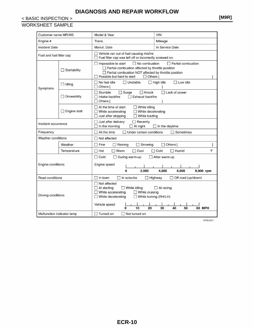
Diagnostic Work Sheet INFOID:0000000001581366
DESCRIPTIONThere are many operating conditions that lead to the malfunction ofengine components. A good grasp of such conditions can make trou-bleshooting faster and more accurate.In general, each customer feels differently about a incident. It isimportant to fully understand the symptoms or conditions for a cus-tomer complaint.Utilize a diagnostic worksheet like the one on the next page in orderto organize all the information for troubleshooting.Some conditions may cause the MIL to come on steady or blink andDTC to be detected. Examples:• Vehicle ran out of fuel, which caused the engine to misfire.• Fuel filler cap was left off or incorrectly screwed on, allowing fuel to
evaporate into the atmosphere.
SEF907L
ECR-9
[M9R]DIAGNOSIS AND REPAIR WORKFLOW
< BASIC INSPECTION >
WORKSHEET SAMPLE
MTBL0017
ECR-10
INSPECTION AND ADJUSTMENT[M9R]
C
D
E
F
G
H
I
J
K
L
M
A
CR
N
P
O
< BASIC INSPECTION >
E
INSPECTION AND ADJUSTMENTBASIC INSPECTION
BASIC INSPECTION : Special Repair Requirement INFOID:0000000001581367
1.INSPECTION START
1. Check service records for any recent repairs that may indicate a related incident.2. Check the current need for scheduled maintenance, especially for fuel filter and air cleaner filter. Refer to
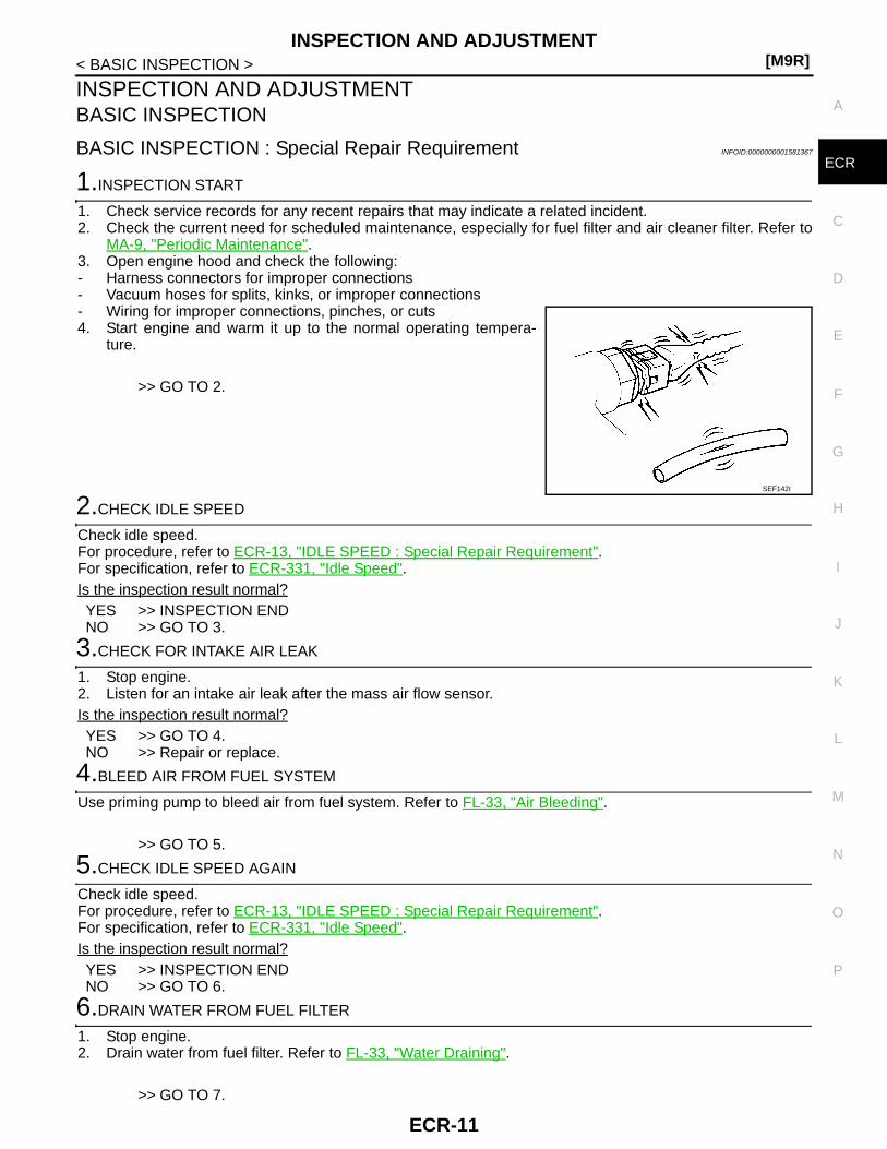
MA-9, "Periodic Maintenance".3. Open engine hood and check the following:- Harness connectors for improper connections- Vacuum hoses for splits, kinks, or improper connections- Wiring for improper connections, pinches, or cuts4. Start engine and warm it up to the normal operating tempera-
ture.
>> GO TO 2.
2.CHECK IDLE SPEED
Check idle speed.For procedure, refer to ECR-13, "IDLE SPEED : Special Repair Requirement".For specification, refer to ECR-331, "Idle Speed".Is the inspection result normal?YES >> INSPECTION ENDNO >> GO TO 3.
3.CHECK FOR INTAKE AIR LEAK
1. Stop engine.2. Listen for an intake air leak after the mass air flow sensor.Is the inspection result normal?YES >> GO TO 4.NO >> Repair or replace.
4.BLEED AIR FROM FUEL SYSTEM
Use priming pump to bleed air from fuel system. Refer to FL-33, "Air Bleeding".
>> GO TO 5.
5.CHECK IDLE SPEED AGAIN
Check idle speed.For procedure, refer to ECR-13, "IDLE SPEED : Special Repair Requirement".For specification, refer to ECR-331, "Idle Speed".Is the inspection result normal?YES >> INSPECTION ENDNO >> GO TO 6.
6.DRAIN WATER FROM FUEL FILTER
1. Stop engine.2. Drain water from fuel filter. Refer to FL-33, "Water Draining".
>> GO TO 7.
SEF142I
ECR-11

[M9R]INSPECTION AND ADJUSTMENT
< BASIC INSPECTION >
7.CHECK IDLE SPEED AGAIN
Check idle speed.For procedure, refer to ECR-13, "IDLE SPEED : Special Repair Requirement".For specification, refer to ECR-331, "Idle Speed".Is the inspection result normal?YES >> INSPECTION ENDNO >> GO TO 8.
8.CHECK AIR CLEANER FILTER
1. Stop engine.2. Check air cleaner filter for clogging or breaks.Is the inspection result normal?YES >> GO TO 9.NO >> Replace air cleaner filter.
9.CHECK BATTERY VOLTAGE
Check battery voltage.
Is the inspection result normal?YES >> GO TO 11.NO >> GO TO 10.
10.CHECK BATTERY
Refer to PG-3, "Work Flow".Is the inspection result normal?YES >> Check charging system. Refer to CHG-5, "M9R/HR16DE/MR20DE MODELS : Work Flow".NO >> Repair or replace.
11.CHECK COMPRESSION PRESSURE
Check compression pressure. Refer to EM-351, "Inspection".Is the inspection result normal?YES >> GO TO 12.NO >> Follow the instruction of “CHECKING COMPRESSION PRESSURE”.
12.CHECK IDLE SPEED AGAIN
Check idle speed.For procedure, refer to ECR-13, "IDLE SPEED : Special Repair Requirement".For specification, refer to ECR-331, "Idle Speed".Is the inspection result normal?YES >> INSPECTION ENDNO >> 1. Replace fuel injector.
2. Perform ECR-14, "INJECTOR ADJUSTMENT VALUE REGISTRATION : Special RepairRequirement".
3. Perform ECR-14, "ZFC VALUE RESET : Special Repair Requirement".4. GO TO 2.
ADDITIONAL SERVICE WHEN REPLACING CONTROL UNIT
ADDITIONAL SERVICE WHEN REPLACING CONTROL UNIT : DescriptionINFOID:0000000001581368
When replacing ECM, this procedure must be performed.
ADDITIONAL SERVICE WHEN REPLACING CONTROL UNIT : Special Repair Re-
Voltage: More than 12.13V
ECR-12

INSPECTION AND ADJUSTMENT[M9R]
C
D
E
F
G
H
I
J
K
L
M
A
CR
N
P
O
< BASIC INSPECTION >
E
quirement INFOID:0000000001581369
1.PERFORM INJECTOR ADJUSTMENT VALUE REGISTRATION
Perform ECR-14, "INJECTOR ADJUSTMENT VALUE REGISTRATION : Special Repair Requirement".
>> GO TO 2.
2.PERFORM ZFC VALVE RESET
Perform ECR-14, "ZFC VALUE RESET : Special Repair Requirement".
>> GO TO 3.
3.PERFORM EGR VOLUME CONTROL VALVE CLOSED POSITION LEARNING
Perform ECR-15, "EGR VOLUME CONTROL VALVE CLOSED POSITION LEARNING : Special RepairRequirement".
>> GO TO 4.
4.PERFORM THROTTLE VALVE CLOSED POSITION LEARNING
Perform ECR-16, "THROTTLE VALVE CLOSED POSITION LEARNING : Special Repair Requirement".
>> GO TO 5.
5.PERFORM DPF DATA CLEAR
Perform ECR-17, "DPF DATA CLEAR : Special Repair Requirement".
>> GO TO 6.
6.PERFORM AIR FUEL RATIO LEARNING VALVE CLEAR
Perform ECR-18, "AIR FUEL RATIO SENSOR LEARNING VALUE CLEAR : Special Repair Requirement".
>> ENDIDLE SPEED
IDLE SPEED : Description INFOID:0000000001581370
This describes how to check the idle speed. For the actual procedure, follow the instructions in “BASICINSPECTION”.
IDLE SPEED : Special Repair Requirement INFOID:0000000001581371
1.CHECK IDLE SPEED
With CONSULT-IIICheck idle speed in “DATA MONITOR” mode with CONSULT-III.
With GSTCheck idle speed with Service $01 of GST.
>> INSPECTION ENDZFC VALUE RESET
ZFC VALUE RESET : Description INFOID:0000000001581372
Wear of injector opening portion (blocking or enlargement of the hall) due to secular change causes error ofinjected amount of fuel resulting in smoke or large noise.To prevent these conditions, it is necessary to reset ZFC (Zero Fuel Calibration) and NVC (Nominal VoltageCalibration).
ECR-13
[M9R]INSPECTION AND ADJUSTMENT
< BASIC INSPECTION >The calibration shall be performed after the following operation.• ECM replacement or reprogramming• Injector replacement
ZFC VALUE RESET : Special Repair Requirement INFOID:0000000001581373
1.START
1. Turn ignition switch ON.2. Perform “ZFC VALUE RESET ” in WORK SUPPORT mode with CONSULT-III.3. Wait at least 10 seconds.
>> ENDINJECTOR ADJUSTMENT VALUE REGISTRATION
INJECTOR ADJUSTMENT VALUE REGISTRATION : Description INFOID:0000000001581374
Injector adjustment value indicates manufacturing tolerance and the value is printed on the top of fuel injector.The injector adjustment value which is correctly stored in ECM is needed for precise fuel injection control.A performance of emission control and a drivability may effect when there is a mismatch between the followingtwo values.• The injector adjustment value stored in ECM• The injector adjustment value of the injector which is installed on the vehicleInjector Adjustment Value Registration must be performed after the following cases.• Injector(s) are replaced.• ECM is replaced.For the first case, Injector Adjustment Value Registration for the replaced fuel injector must be performed. Andfor the second case, Injector Adjustment Value Registration for all the fuel injectors must be performed.
INJECTOR ADJUSTMENT VALUE REGISTRATION : Special Repair RequirementINFOID:0000000001581375
1.START
NOTE:• Before performing this procedure, record injector adjustment value printed on a fuel injector.1. Turn ignition switch ON (engine stopped).2. Select “INJ ADJ VAL REGIST” in “WORK SUPPORT” mode with CONSULT-III.3. Touch “START”.
NOTE:When touching “START”, CONSULT-III reads injector adjustment values stored in ECM.
4. Select the number of the cylinder which needs Injector Adjustment Value Registration.5. Input injector adjustment value, and touch “ENTER”.
NOTE:Input injector adjustment value is stored in CONSULT-III.
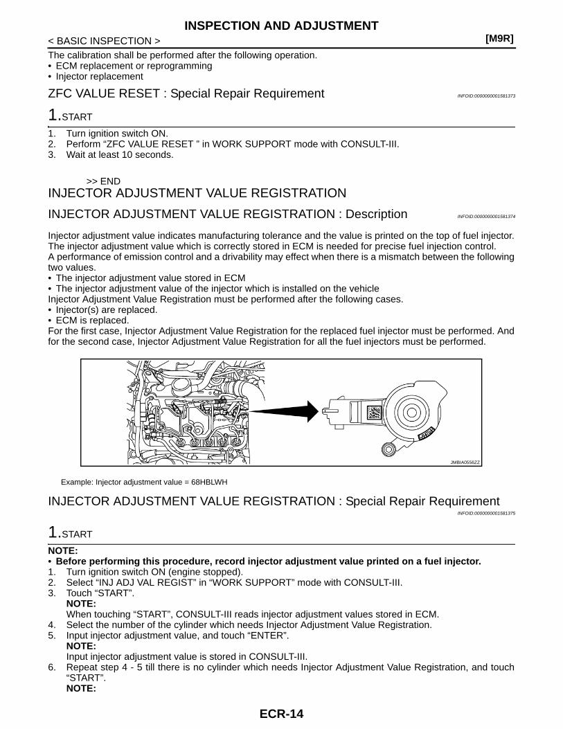
6. Repeat step 4 - 5 till there is no cylinder which needs Injector Adjustment Value Registration, and touch“START”.NOTE:
Example: Injector adjustment value = 68HBLWH
JMBIA0556ZZ
ECR-14
INSPECTION AND ADJUSTMENT[M9R]
C
D
E
F
G
H
I
J
K
L
M
A
CR
N
P
O
< BASIC INSPECTION >
E
When touching “START”, injector adjustment values stored in CONSULT-III are written onto ECM mem-ory.
7. After “CMND FINISHED” is displayed, make sure that the following values are same for each cylinder.- Injector adjustment value which is printed on a fuel injector.- Injector adjustment value which is displayed on CONSULT-III screen.
NOTE:• In this step, CONSULT-III reads injector adjustment values stored in ECM and displays the values on
the CONSULT-III screen. This is for checking if injector adjustment values are written onto ECM memorycorrectly.
• If DTC is detected, perform DTC Confirmation Procedure for the DTC, and check if the same DTC isdetected again.
>> ENDEGR VOLUME CONTROL VALVE CLOSED POSITION LEARNING VALUECLEAR
EGR VOLUME CONTROL VALVE CLOSED POSITION LEARNING VALUE CLEAR : Description INFOID:0000000001581376
EGR volume control valve closed position learning value should be cleared under the following cases.• EGR volume control valve is removed.• EGR volume control valve is replaced.
EGR VOLUME CONTROL VALVE CLOSED POSITION LEARNING VALUE CLEAR : Special Repair Requirement INFOID:0000000001581377
1.START
1. Start engine and warm it up to normal operating temperature.2. Turn ignition switch OFF and wait at least 30 seconds.3. Turn ignition switch ON.4. Select “EGR/V LEARN CLR” in “WORK SUPPORT” mode with CONSULT-III.5. Touch “CLEAR” and wait a few seconds.6. Make sure the “CMPLT” is displayed on CONSULT-III screen.
>> ENDEGR VOLUME CONTROL VALVE CLOSED POSITION LEARNING
EGR VOLUME CONTROL VALVE CLOSED POSITION LEARNING : DescriptionINFOID:0000000001581378
EGR Volume Control Valve Closed Position Learning is an operation to learn the fully closed position of theEGR volume control valve by monitoring the EGR volume control valve control position sensor output signal. Itmust be performed under any of the following conditions:• EGR volume control valve is removed.• EGR volume control valve is replaced.• ECM is replaced.
EGR VOLUME CONTROL VALVE CLOSED POSITION LEARNING : Special Repair Requirement INFOID:0000000001581379
1.START
1. Start engine and warm it up to normal operating temperature.2. Turn ignition switch OFF and wait at least 10 seconds.
Make sure that EGR volume control valve moves during above 10 seconds by confirming the operatingsound.
>> END
ECR-15

[M9R]INSPECTION AND ADJUSTMENT
< BASIC INSPECTION >
THROTTLE VALVE CLOSED POSITION LEARNING VALUE CLEAR
THROTTLE VALVE CLOSED POSITION LEARNING VALUE CLEAR : DescriptionINFOID:0000000001581380
Throttle valve closed position learning value should be cleared under the following cases.• Electric throttle control actuator is removed.• Electric throttle control actuator is replaced.
THROTTLE VALVE CLOSED POSITION LEARNING VALUE CLEAR : Special Repair Requirement INFOID:0000000001581381
1.START
1. Start engine and warm it up to normal operating temperature.2. Turn ignition switch OFF and wait at least 30 seconds.3. Turn ignition switch ON.4. Select “TP POS LEARN CLR” in “WORK SUPPORT” mode with CONSULT-III.5. Touch “CLEAR” and wait a few seconds.6. Make sure the “CMPLT” is displayed on CONSULT-III screen.
>> ENDTHROTTLE VALVE CLOSED POSITION LEARNING
THROTTLE VALVE CLOSED POSITION LEARNING : Description INFOID:0000000001581382
Throttle Valve Closed Position Learning is an operation to learn the fully closed position of the throttle valve bymonitoring the throttle position sensor output signal. It must be performed each time harness connector ofelectric throttle control actuator or ECM is disconnected.• Electric throttle control actuator is removed.• Electric throttle control actuator is replaced.• ECM is replaced.
THROTTLE VALVE CLOSED POSITION LEARNING : Special Repair RequirementINFOID:0000000001581383
1.START
1. Make sure that accelerator pedal is fully released.2. Turn ignition switch ON.3. Turn ignition switch OFF and wait at least 10 seconds.
Make sure that throttle valve moves during above 10 seconds by confirming the operating sound.
>> ENDSERVICE REGENERATION
SERVICE REGENERATION : Description INFOID:0000000001581384
Service Regeneration is performed with CONSULT-III to reduce particulate matter in DPF. Service Regenera-tion should be performed in the following cases.• ECM enters fail-safe mode because the amount of particulate matter in DPF reaches the specified level.
NOTE:When ECM enters fail-safe mode because the amount of particulate matter in DPF reaches the specifiedlevel, check whether or not DTC is stored in ECM. In the case of DTC stored, perform the Diagnostic Proce-dure for the DTC.
• ECM is replaced.NOTE:Based on the signal from sensors ECM measures the amount of particulate matter in DPF and stores thevalue in EEPROM (Electrically Erasable Programmable Read Only Memory). When ECM is replaced asnew one, there is a difference between the actual amount of particulate matter and the value stored in newECM, because the value stored in new ECM is initialized one. In the case above, ECM can not perform
ECR-16
INSPECTION AND ADJUSTMENT[M9R]
C
D
E
F
G
H
I
J
K
L
M
A
CR
N
P
O
< BASIC INSPECTION >
E
regeneration control correctly. So, perform service regeneration to make the amount of particulate matter inDPF zero.
• Component Inspection for DPF is performed.CAUTION:Always replace engine oil and engine oil filter after service regeneration. Fuel mixes with engine oilduring service regeneration. The mixture does not occur during the regeneration which is automati-cally performed under normal operation.
SERVICE REGENERATION : Special Repair Requirement INFOID:0000000001581385
1.START
1. Turn ignition switch ON.2. Select “SERVC REGENERATION” in “WORK SUPPORT” mode with CONSULT-III.3. Touch “START”.4. Wait until “CMPT” is displayed.
NOTE:• Make sure that accelerator pedal is fully released during service regeneration, or service regeneration is
canceled. When service regeneration is canceled, retry from step1.• It will take approximately 40 minutes until “CMPLT” is displayed.
5. Turn ignition switch OFF.6. Replace engine oil and engine oil filter.
>> ENDDPF DATA CLEAR
DPF DATA CLEAR : Description INFOID:0000000001581386
Perform “DPF DATA CLEAR” in “WORK SUPPORT” mode with CONSULT-III when oxidation catalyst withDPF is replaced as new one. Based on the signal from sensors ECM estimates the amount of particulate mat-ter in DPF and stores the value in EEPROM as DPF data. When oxidation catalyst with DPF is replaced asnew one, there is a difference between DPF data stored in ECM and the actual amount of particulate matter inDPF, because no particulate matter is trapped in new DPF. In this case, ECM can not perform regenerationcontrol correctly. So perform “DPF DATA CLEAR” in “WORK SUPPORT” mode with CONSULT-III to clearDPF data stored in ECM.CAUTION:Never perform “DPF DATA CLEAR” in “WORK SUPPORT” mode with CONSULT-III when oxidation cat-alyst with DPF is not replaced as new one. DPF may be damaged because regeneration is not per-formed at appropriate timing.
DPF DATA CLEAR : Special Repair Requirement INFOID:0000000001581387
1.START
1. Turn ignition switch ON.2. Select “DPF DATA CLEAR” in “WORK SUPPORT” mode with CONSULT-III.3. Touch “CLEAR” and wait a few seconds.4. Make sure that “CMPLT” is displayed on CONSULT-III screen.
>> ENDAIR FUEL RATIO SENSOR LEARNING VALUE CLEAR
AIR FUEL RATIO SENSOR LEARNING VALUE CLEAR : Description INFOID:0000000001581388
ECM learns the output characteristic of A/F sensor 1 to perform the control of DPF regeneration precisely. A/Fsensor learning value should be cleared under the following conditions.• A/F sensor 1 is changed.• ECM is replaced with used one which stores the A/F Sensor Learning Value of another A/F sensor 1.
ECR-17

[M9R]INSPECTION AND ADJUSTMENT
< BASIC INSPECTION >
AIR FUEL RATIO SENSOR LEARNING VALUE CLEAR : Special Repair RequirementINFOID:0000000001581389
1.START
1. Turn ignition switch ON.2. Select “A/F SEN LEAN CLR” in “WORK SUPPORT” mode with CONSULT-III.3. Touch “CLEAR” and wait a few seconds.4. Make sure that “CMPLT” is displayed on CONSULT-III screen.
>> END
ECR-18
ENGINE CONTROL SYSTEM[M9R]
C
D
E
F
G
H
I
J
K
L
M
A
CR
N
P
O
< FUNCTION DIAGNOSIS >
E
FUNCTION DIAGNOSISENGINE CONTROL SYSTEM
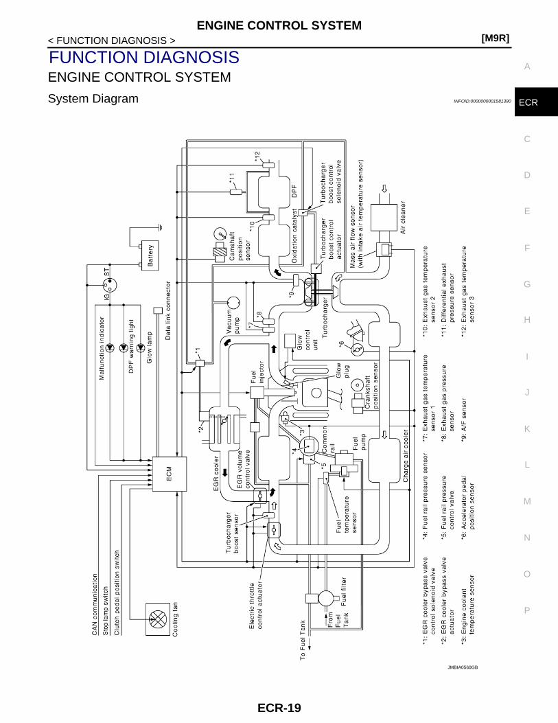
System Diagram INFOID:0000000001581390
JMBIA0560GB
ECR-19
[M9R]ENGINE CONTROL SYSTEM
< FUNCTION DIAGNOSIS >
System Description INFOID:0000000001581391
ECM performs various controls such as fuel injection control and furl pressure control.
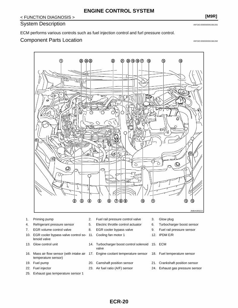
Component Parts Location INFOID:0000000001581392
1. Priming pump 2. Fuel rail pressure control valve 3. Glow plug
4. Refrigerant pressure sensor 5. Electric throttle control actuator 6. Turbocharger boost sensor
7. EGR volume control valve 8. EGR cooler bypass valve 9. Fuel rail pressure sensor
10. EGR cooler bypass valve control so-lenoid valve
11. Cooling fan motor 1 12. IPDM E/R
13. Glow control unit 14. Turbocharger boost control solenoid valve
15. ECM
16. Mass air flow sensor (with intake air temperature sensor)
17. Engine coolant temperature sensor 18. Fuel temperature sensor
19. Fuel pump 20. Camshaft position sensor 21. Crankshaft position sensor
22. Fuel injector 23. Air fuel ratio (A/F) sensor 24. Exhaust gas pressure sensor
25. Exhaust gas temperature sensor 1
JMBIA0692ZZ
ECR-20

ENGINE CONTROL SYSTEM[M9R]
C
D
E
F
G
H
I
J
K
L
M
A
CR
N
P
O
< FUNCTION DIAGNOSIS >
E
: Vehicle front
1. Mass air flow sensor (with intake air temperature sensor)
2. Engine coolant temperature sensor
: Vehicle front
1. Camshaft Position Sensor 2. Fuel injector
: Vehicle front
1. Crankshaft position sensor 2. Turbocharger boost control solenoid valve
JMBIA0489ZZ
JMBIA0490ZZ
JMBIA0491ZZ
JMBIA0693ZZ
ECR-21

[M9R]ENGINE CONTROL SYSTEM
< FUNCTION DIAGNOSIS >
: Vehicle front
1. Electric throttle control actuator 2. Turbocharger boost sensor 3. EGR volume control valve
4. Refrigerant pressure sensor
: Vehicle front
1. Fuel rail pressure sensor 2. Fuel rail pressure control valve
: Vehicle front
1. Fuel temperature sensor 2. Fuel pump 3. EGR cooler bypass valve control so-lenoid valve
: Vehicle front
1. Exhaust gas temperature sensor 1 2. Exhaust gas pressure sensor 3. Air fuel ratio (A/F) sensor
JMBIA0493ZZ
JMBIA0494ZZ
JMBIA0495ZZ
ECR-22

ENGINE CONTROL SYSTEM[M9R]
C
D
E
F
G
H
I
J
K
L
M
A
CR
N
P
O
< FUNCTION DIAGNOSIS >
E
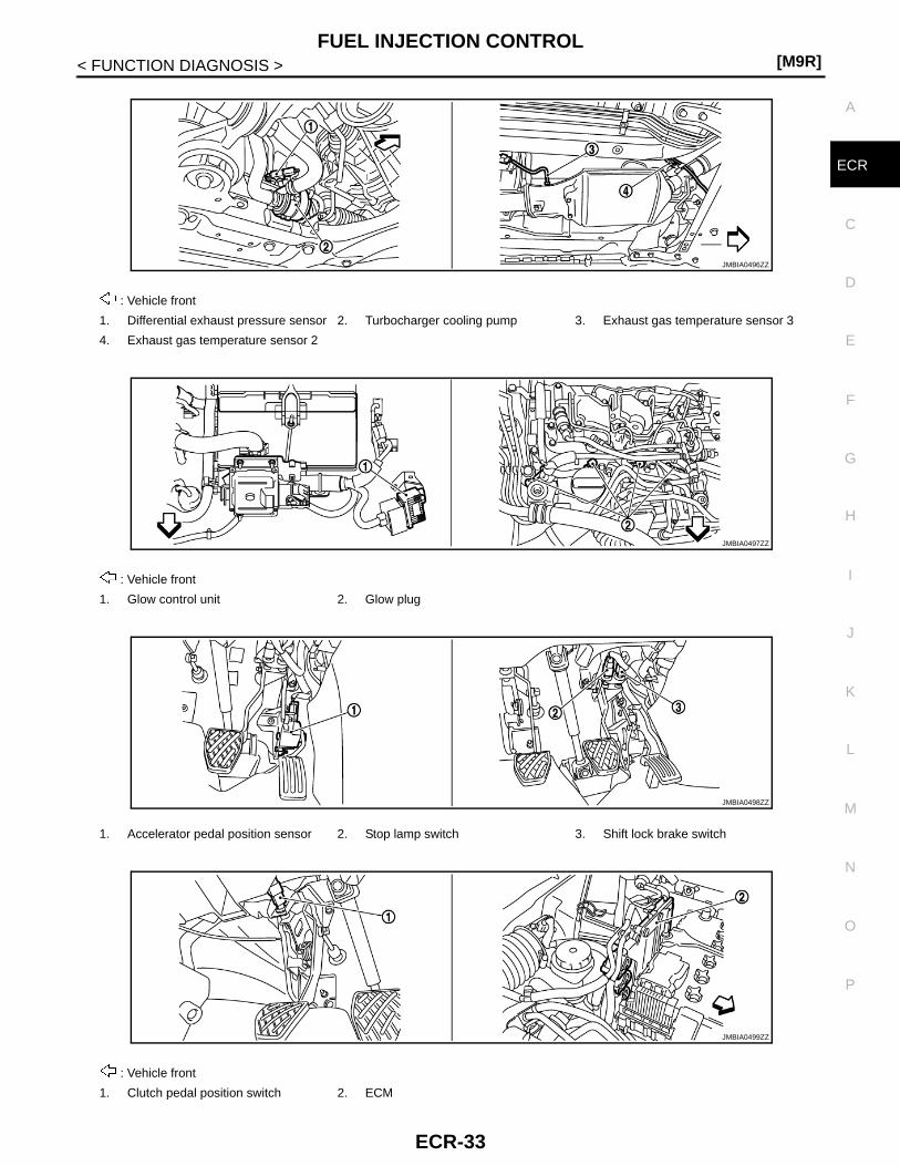
: Vehicle front
1. Differential exhaust pressure sensor 2. Turbocharger cooling pump 3. Exhaust gas temperature sensor 3
4. Exhaust gas temperature sensor 2
: Vehicle front
1. Glow control unit 2. Glow plug
1. Accelerator pedal position sensor 2. Stop lamp switch 3. Shift lock brake switch
: Vehicle front
1. Clutch pedal position switch 2. ECM
JMBIA0496ZZ
JMBIA0497ZZ
JMBIA0498ZZ
JMBIA0499ZZ
ECR-23

[M9R]ENGINE CONTROL SYSTEM
< FUNCTION DIAGNOSIS >
Component Description INFOID:0000000001581393
1. ASDC steering switch 2. CANSEL switch 3. RESUME/ACCCELERATE switch
4. SET/COAST switch 5. MAIN SWITCH
JMBIA0483ZZ
Component Reference
A/F sensor 1 ECR-137, "Description"
A/F sensor 1 heater ECR-145, "Description"
Accelerator pedal position sensor ECR-158, "Description"
ASCD steering switch ECR-192, "Description"
Barometric pressure sensor ECR-247, "Description"
Stop lamp switch ECR-195, "Description"
Camshaft position sensor ECR-169, "Description"
Cooling fan motor ECR-283, "Description"
Crankshaft position sensor ECR-167, "Description"
Clutch pedal position switch ECR-281, "Description"
Differential exhaust pressure sensor ECR-268, "Description"
EGR cooler bypass valve control solenoid valve ECR-261, "Description"
EGR volume control valve ECR-180, "Description"
EGR volume control valve control position sensor ECR-175, "Description"
Engine coolant temperature sensor ECR-132, "Description"
Exhaust gas pressure sensor ECR-178, "Description"
Exhaust gas temperature sensor 1 ECR-187, "Description"
Exhaust gas temperature sensor 2 ECR-231, "Description"
Exhaust gas temperature sensor 3 ECR-263, "Description"
Fuel injector ECR-155, "Description"
Fuel rail pressure control valve ECR-256, "Description"
Fuel rail pressure sensor ECR-150, "Description"
Fuel temperature sensor ECR-148, "Description"
Intake air temperature sensor ECR-130, "Description"
Mass air flow sensor ECR-123, "Description"
Refrigerant pressure sensor ECR-185, "Description"
Throttle position sensor ECR-134, "Description"
Turbocharger boost control solenoid valve ECR-117, "Description"
Turbocharger boost sensor ECR-161, "Description"
Turbocharger cooling pump ECR-273, "Description"
Vehicle speed sensor ECR-184, "Description"
ECR-24

FUEL INJECTION CONTROL[M9R]
C
D
E
F
G
H
I
J
K
L
M
A
CR
N
P
O
< FUNCTION DIAGNOSIS >
E
FUEL INJECTION CONTROL
System Description INFOID:0000000001581394
FUEL INJECTION CONTROL
System Diagram
System DescriptionINPUT/OUTPUT SIGNAL CHART
*: This signal is sent to the ECM through CAN communication line.
SYSTEM DESCRIPTIONThree types of fuel injection control are provided to accommodate engine operating conditions; normal control,idle control and start control. The ECM determines the appropriate fuel injection control. Above each control,the amount of fuel injected is adjusted to improve engine performance. Pulse signals are sent to fuel injectorsaccording to the input signals to adjust the amount of fuel injected to preset value.
JMBIA0659GB
Sensor Input Signal to ECM ECM function Actuator
Crankshaft position sensor Engine speedPiston position
Fuel injection control Fuel injector
Camshaft position sensor
Intake air temperature sensor Intake air temperature
Engine coolant temperature sensor Engine coolant temperature
Fuel rail pressure sensor Fuel rail pressure sensor
Accelerator pedal position sensor Accelerator pedal position
Turbocharger boost sensor Turbocharger boost
Ignition switch Start signal
Battery Battery voltage
Mass air flow sensor Amount of intake air
Vehicle speed sensor Vehicle speed*
Air conditioner switch Air conditioner switch*
ECR-25

[M9R]FUEL INJECTION CONTROL
< FUNCTION DIAGNOSIS >
START CONTROL
System Diagram
System DescriptionINPUT/OUTPUT SIGNAL CHART
SYSTEM DESCRIPTIONWhen ECM detected the engine revolution pulse at engine cranking, the ECM adapts the fuel injection systemfor the start control. The amount of fuel injected at engine starting is a preset program value in the ECM. Theprogram is determined by the engine speed, engine coolant temperature, intake air temperature and fuel railpressure. For better startability under cool engine conditions, the lower the coolant temperature becomes, thegreater the amount of fuel injected. The ECM ends the start control when the engine speed reaches the spe-cific value, and shifts the control to the normal or idle control.
IDLE CONTROL
JMBIA0646GB
Sensor Input Signal to ECM ECM function Actuator
Crankshaft position sensor Engine speedPiston position
Fuel injection control(Start control)
Fuel injectorFuel pump
Camshaft position sensor
Intake air temperature sensor Intake air temperature
Engine coolant temperature sensor Engine coolant temperature
Fuel rail pressure sensor Fuel rail pressure sensor
Ignition switch Start signal
ECR-26

FUEL INJECTION CONTROL[M9R]
C
D
E
F
G
H
I
J
K
L
M
A
CR
N
P
O
< FUNCTION DIAGNOSIS >
E
System Diagram
System DescriptionINPUT/OUTPUT SIGNAL CHART
*: This signal is sent to the ECM through CAN communication line.
SYSTEM DESCRIPTIONWhen the ECM determines that the engine speed is at idle, the fuel injection system is adapted for the idlecontrol. The ECM regulates the amount of fuel injected corresponding to changes in load applied to the engineto keep engine speed constant. The ECM also provides the system with a fast idle control in response to theengine coolant temperature signal.
NORMAL CONTROL
JMBIA0647GB
Sensor Input Signal to ECM ECM function Actuator
Crankshaft position sensor Engine speed
Fuel injection control(Idle control)
Fuel injectorFuel pump
Accelerator pedal position sensor Accelerator pedal position
Engine coolant temperature sensor Engine coolant temperature
Intake air temperature sensor Intake air temperature
Fuel rail pressure sensor Fuel rail pressure sensor
Battery Battery voltage
Vehicle speed sensor Vehicle speed*
Air conditioner switch Air conditioner switch*
ECR-27

[M9R]FUEL INJECTION CONTROL
< FUNCTION DIAGNOSIS >System Diagram
System DescriptionINPUT/OUTPUT SIGNAL CHART
SYSTEM DESCRIPTIONThe amount of fuel injected under normal driving conditions is determined according to sensor signals. Thecrankshaft position sensor detects engine speed, intake air temperature sensor detects intake air temperature,turbocharger boost sensor detects turbocharger boost, the accelerator pedal position sensor detects accelera-tor pedal position, fuel rail pressure sensor detects fuel rail pressure and other sensors detects each signal.These sensors send signals to the ECM. The fuel injection data, predetermined by correlation between vari-ous engine speeds, accelerator pedal position and fuel rail pressure are stored in the ECM memory, forming amap. The ECM detainees the optimal amount of fuel to be injected using the sensor signals in comparisonwith the map.
MAXIMUM AMOUNT CONTROL
System Diagram
System DescriptionINPUT/OUTPUT SIGNAL CHART
JMBIA0648GB
Sensor Input Signal to ECM ECM function Actuator
Crankshaft position sensor Engine speed
Fuel injection control(Normal control)
Fuel injector
Accelerator pedal position sensor Accelerator pedal position
Fuel rail pressure sensor Fuel rail pressure sensor
Intake air temperature sensor Intake air temperature
Turbocharger boost sensor Turbocharger boost
JMBIA0650GB
ECR-28

FUEL INJECTION CONTROL[M9R]
C
D
E
F
G
H
I
J
K
L
M
A
CR
N
P
O
< FUNCTION DIAGNOSIS >
E
SYSTEM DESCRIPTIONThe maximum injection amount is controlled to an optimum by the engine speed, intake air amount, enginecoolant temperature and accelerator opening in accelerator with the driving conditions. This prevents the over-supply of the injection amount caused by decreased air density at a high altitude or during a system failure.
FUELCUT CONTROL
System Diagram
System DescriptionINPUT/OUTPUT SIGNAL CHART
*: This signal is sent to the ECM though ECM CAN communication line.
SYSTEM DESCRIPTIONThe ECM sends a fuel cut signal to the fuel injectors and fuel pump during deceleration for better fuel effi-ciency. The ECM determines the time of deceleration according to signals from the accelerator pedal positionsensor, crankshaft positions sensor and vehicle speed sensor.
Sensor Input Signal to ECM ECM function Actuator
Crankshaft position sensor Engine speed
Fuel injection control(Maximum control)
Fuel injectorAccelerator pedal position sensor Accelerator pedal position
Engine coolant temperature sensor Engine coolant temperature
Mass air flow sensor Amount of intake air
JMBIA0651GB
Sensor Input Signal to ECM ECM function Actuator
Vehicle speed sensor Vehicle speed*Fuel injection control(Fuel cut control)
Fuel injectorCrankshaft position sensor Engine speed
Accelerator pedal position sensor Accelerator pedal position
ECR-29

[M9R]FUEL INJECTION CONTROL
< FUNCTION DIAGNOSIS >
Component Parts Location INFOID:0000000001585893
1. Priming pump 2. Fuel rail pressure control valve 3. Glow plug
4. Refrigerant pressure sensor 5. Electric throttle control actuator 6. Turbocharger boost sensor
7. EGR volume control valve 8. EGR cooler bypass valve 9. Fuel rail pressure sensor
10. EGR cooler bypass valve control so-lenoid valve
11. Cooling fan motor 1 12. IPDM E/R
13. Glow control unit 14. Turbocharger boost control solenoid valve
15. ECM
16. Mass air flow sensor (with intake air temperature sensor)
17. Engine coolant temperature sensor 18. Fuel temperature sensor
19. Fuel pump 20. Camshaft position sensor 21. Crankshaft position sensor
22. Fuel injector 23. Air fuel ratio (A/F) sensor 24. Exhaust gas pressure sensor
25. Exhaust gas temperature sensor 1
JMBIA0692ZZ
ECR-30

FUEL INJECTION CONTROL[M9R]
C
D
E
F
G
H
I
J
K
L
M
A
CR
N
P
O
< FUNCTION DIAGNOSIS >
E
: Vehicle front
1. Mass air flow sensor (with intake air temperature sensor)
2. Engine coolant temperature sensor
: Vehicle front
1. Camshaft Position Sensor 2. Fuel injector
: Vehicle front
1. Crankshaft position sensor 2. Turbocharger boost control solenoid valve
JMBIA0489ZZ
JMBIA0490ZZ
JMBIA0491ZZ
JMBIA0693ZZ
ECR-31

[M9R]FUEL INJECTION CONTROL
< FUNCTION DIAGNOSIS >
: Vehicle front
1. Electric throttle control actuator 2. Turbocharger boost sensor 3. EGR volume control valve
4. Refrigerant pressure sensor
: Vehicle front
1. Fuel rail pressure sensor 2. Fuel rail pressure control valve
: Vehicle front
1. Fuel temperature sensor 2. Fuel pump 3. EGR cooler bypass valve control so-lenoid valve
: Vehicle front
1. Exhaust gas temperature sensor 1 2. Exhaust gas pressure sensor 3. Air fuel ratio (A/F) sensor
JMBIA0493ZZ
JMBIA0494ZZ
JMBIA0495ZZ
ECR-32
FUEL INJECTION CONTROL[M9R]
C
D
E
F
G
H
I
J
K
L
M
A
CR
N
P
O
< FUNCTION DIAGNOSIS >
E
: Vehicle front
1. Differential exhaust pressure sensor 2. Turbocharger cooling pump 3. Exhaust gas temperature sensor 3
4. Exhaust gas temperature sensor 2
: Vehicle front
1. Glow control unit 2. Glow plug
1. Accelerator pedal position sensor 2. Stop lamp switch 3. Shift lock brake switch
: Vehicle front
1. Clutch pedal position switch 2. ECM
JMBIA0496ZZ
JMBIA0497ZZ
JMBIA0498ZZ
JMBIA0499ZZ
ECR-33

[M9R]FUEL INJECTION CONTROL
< FUNCTION DIAGNOSIS >
Component Description INFOID:0000000001581396
1. ASDC steering switch 2. CANSEL switch 3. RESUME/ACCCELERATE switch
4. SET/COAST switch 5. MAIN SWITCH
JMBIA0483ZZ
Component Reference
Accelerator pedal position sensor ECR-158, "Description"
Camshaft position sensor ECR-169, "Description"
Crankshaft position sensor ECR-167, "Description"
Clutch pedal position switch ECR-281, "Description"
Engine coolant temperature sensor ECR-132, "Description"
Fuel injector ECR-155, "Description"
Fuel rail pressure sensor ECR-150, "Description"
Mass air flow sensor ECR-123, "Description"
Turbocharger boost sensor ECR-161, "Description"
Vehicle speed sensor ECR-184, "Description"
ECR-34

FUEL INJECTION TIMING CONTROL SYSTEM[M9R]
C
D
E
F
G
H
I
J
K
L
M
A
CR
N
P
O
< FUNCTION DIAGNOSIS >
E
FUEL INJECTION TIMING CONTROL SYSTEM
System Diagram INFOID:0000000001581397
System Description INFOID:0000000001581398
INPUT/OUTPUT SIGNAL CHART
SYSTEM DESCRIPTIONThe target fuel injection timing in accordance with the engine speed and the fuel injection amount are recordedas a map in the ECM beforehand. The ECM determines the optimum injection timing using sensor signalsaccordance with the map.
JMBIA0658GB
Input signal to ECM ECM function ECM function Actuator
Crankshaft position sensor Engine speed
Fuel injection tim-ing control
Fuel injector
Camshaft position sensor PIston position
Engine coolant temperature sensor Engine coolant temperature
Intake air temperature Intake air temperature sensor
Fuel rail pressure Fuel rail pressure
Accelerator pedal position sensor Accelerator pedal position
Turbocharger boost sensor Turbocharger boost
ECR-35

[M9R]FUEL INJECTION TIMING CONTROL SYSTEM
< FUNCTION DIAGNOSIS >
Component Parts Location INFOID:0000000001585894
1. Priming pump 2. Fuel rail pressure control valve 3. Glow plug
4. Refrigerant pressure sensor 5. Electric throttle control actuator 6. Turbocharger boost sensor
7. EGR volume control valve 8. EGR cooler bypass valve 9. Fuel rail pressure sensor
10. EGR cooler bypass valve control so-lenoid valve
11. Cooling fan motor 1 12. IPDM E/R
13. Glow control unit 14. Turbocharger boost control solenoid valve
15. ECM
16. Mass air flow sensor (with intake air temperature sensor)
17. Engine coolant temperature sensor 18. Fuel temperature sensor
19. Fuel pump 20. Camshaft position sensor 21. Crankshaft position sensor
22. Fuel injector 23. Air fuel ratio (A/F) sensor 24. Exhaust gas pressure sensor
25. Exhaust gas temperature sensor 1
JMBIA0692ZZ
ECR-36

FUEL INJECTION TIMING CONTROL SYSTEM[M9R]
C
D
E
F
G
H
I
J
K
L
M
A
CR
N
P
O
< FUNCTION DIAGNOSIS >
E
: Vehicle front
1. Mass air flow sensor (with intake air temperature sensor)
2. Engine coolant temperature sensor
: Vehicle front
1. Camshaft Position Sensor 2. Fuel injector
: Vehicle front
1. Crankshaft position sensor 2. Turbocharger boost control solenoid valve
JMBIA0489ZZ
JMBIA0490ZZ
JMBIA0491ZZ
JMBIA0693ZZ
ECR-37

[M9R]FUEL INJECTION TIMING CONTROL SYSTEM
< FUNCTION DIAGNOSIS >
: Vehicle front
1. Electric throttle control actuator 2. Turbocharger boost sensor 3. EGR volume control valve
4. Refrigerant pressure sensor
: Vehicle front
1. Fuel rail pressure sensor 2. Fuel rail pressure control valve
: Vehicle front
1. Fuel temperature sensor 2. Fuel pump 3. EGR cooler bypass valve control so-lenoid valve
: Vehicle front
1. Exhaust gas temperature sensor 1 2. Exhaust gas pressure sensor 3. Air fuel ratio (A/F) sensor
JMBIA0493ZZ
JMBIA0494ZZ
JMBIA0495ZZ
ECR-38

FUEL INJECTION TIMING CONTROL SYSTEM[M9R]
C
D
E
F
G
H
I
J
K
L
M
A
CR
N
P
O
< FUNCTION DIAGNOSIS >
E
: Vehicle front
1. Differential exhaust pressure sensor 2. Turbocharger cooling pump 3. Exhaust gas temperature sensor 3
4. Exhaust gas temperature sensor 2
: Vehicle front
1. Glow control unit 2. Glow plug
1. Accelerator pedal position sensor 2. Stop lamp switch 3. Shift lock brake switch
: Vehicle front
1. Clutch pedal position switch 2. ECM
JMBIA0496ZZ
JMBIA0497ZZ
JMBIA0498ZZ
JMBIA0499ZZ
ECR-39

[M9R]FUEL INJECTION TIMING CONTROL SYSTEM
< FUNCTION DIAGNOSIS >
Component Description INFOID:0000000001581400
1. ASDC steering switch 2. CANSEL switch 3. RESUME/ACCCELERATE switch
4. SET/COAST switch 5. MAIN SWITCH
JMBIA0483ZZ
Component Reference
Accelerator pedal position sensor ECR-158, "Description"
Camshaft position sensor ECR-169, "Description"
Crankshaft position sensor ECR-167, "Description"
Engine coolant temperature sensor ECR-132, "Description"
Fuel injector ECR-155, "Description"
Fuel rail pressure sensor ECR-150, "Description"
Intake air temperature sensor ECR-130, "Description"
Mass air flow sensor ECR-123, "Description"
Turbocharger boost sensor ECR-161, "Description"
Vehicle speed sensor ECR-184, "Description"
ECR-40

AUTOMATIC SPEED CONTROL DEVICE (ASCD)[M9R]
C
D
E
F
G
H
I
J
K
L
M
A
CR
N
P
O
< FUNCTION DIAGNOSIS >
E
AUTOMATIC SPEED CONTROL DEVICE (ASCD)
System Diagram INFOID:0000000001581401
System Description INFOID:0000000001581402
INPUT/OUTPUT SIGNAL CHART
*: This signal is also sent to the ECM through CAN communication line
BASIC ASCD SYSTEMRefer to Owner's Manual for ASCD operating instructions.Automatic Speed Control Device (ASCD) allows a driver to keep vehicle at predetermined constant speedwithout depressing accelerator pedal. Driver can set vehicle speed in advance between approximately 40 km/h (25 MPH) and 200 km/h (124 MPH).ECM controls throttle angle of electric throttle control actuator to regulate engine speed.Operation status of ASCD is indicated by CRUISE lamp and SET lamp in combination meter. If any malfunc-tion occurs in ASCD system, it automatically deactivates control.NOTE:Always drive vehicle in safe manner according to traffic conditions and obey all traffic laws.
SET OPERATIONPress MAIN switch. (The CRUISE lamp in combination meter illuminates.)When vehicle speed reaches a desired speed between approximately 40 km/h (25 MPH) and 200 km/h (124MPH). press SET/COAST switch. (Then SET lamp in combination meter illuminates.)
ACCELERATE OPERATIONIf the RESUME/ACCELERATE switch is pressed during cruise control driving, increase the vehicle speed untilthe switch is released or vehicle speed reaches maximum speed controlled by the system.And then ASCD will keep the new set speed.
CANCEL OPERATION
JMBIA0721GB
Sensor Input signal to ECM ECM function Actuator
Stop lamp switch Brake pedal operation
ASCD vehicle speed control
Electric throttle control actuator
Stop lamp switch Brake pedal operation*
Clutch pedal position switch (M/T models) Clutch pedal operation
ASCD steering switch ASCD steering switch operation
Park/neutral position (PNP) switch Gear position*
Wheel sensor Vehicle speed*
TCM (A/T models) Powertrain revolution*
ECR-41

[M9R]AUTOMATIC SPEED CONTROL DEVICE (ASCD)
< FUNCTION DIAGNOSIS >When any of following conditions exist, cruise operation will be canceled.• CANCEL switch is pressed• More than 2 switches at ASCD steering switch are pressed at the same time (Set speed will be cleared)• Brake pedal is depressed• Clutch pedal is depressed or gear position is changed to neutral position. (M/T models)• Selector lever is changed to N, P, R position (A/T models)• Vehicle speed decreased to 12 km/h (8 MPH) lower than the set speed• TCS system is operatedWhen the ECM detects any of the following conditions, the ECM will cancel the cruise operation and informthe driver by blinking indicator lamp.• Engine coolant temperature is slightly higher than the normal operating temperature, CRUISE lamp may
blink slowly.When the engine coolant temperature decreases to the normal operating temperature, CRUISE lamp willstop blinking and the cruise operation will be able to work by pressing SET/COAST switch or RESUME/ACCELERATE switch.
• Malfunction for some self-diagnoses regarding ASCD control: SET lamp will blink quickly.If MAIN switch is turned to OFF during ASCD is activated, all of ASCD operations will be canceled and vehiclespeed memory will be erased.
COAST OPERATIONWhen the SET/COAST switch is pressed during cruise control driving, decrease vehicle set speed until theswitch is released. And then ASCD will keep the new set speed.
RESUME OPERATIONWhen the RESUME/ACCELERATE switch is pressed after cancel operation other than pressing MAIN switchis performed, vehicle speed will return to last set speed. To resume vehicle set speed, vehicle condition mustmeet following conditions.• Brake pedal is released• Clutch pedal is released (M/T models)• Selector lever is in other than P and N positions (A/T models)• Vehicle speed is greater than 40 km/h (25 MPH) and less than 200 km/h (124 MPH).
ECR-42

AUTOMATIC SPEED CONTROL DEVICE (ASCD)[M9R]
C
D
E
F
G
H
I
J
K
L
M
A
CR
N
P
O
< FUNCTION DIAGNOSIS >
E
Component Parts Location INFOID:0000000001585895
1. Priming pump 2. Fuel rail pressure control valve 3. Glow plug
4. Refrigerant pressure sensor 5. Electric throttle control actuator 6. Turbocharger boost sensor
7. EGR volume control valve 8. EGR cooler bypass valve 9. Fuel rail pressure sensor
10. EGR cooler bypass valve control so-lenoid valve
11. Cooling fan motor 1 12. IPDM E/R
13. Glow control unit 14. Turbocharger boost control solenoid valve
15. ECM
16. Mass air flow sensor (with intake air temperature sensor)
17. Engine coolant temperature sensor 18. Fuel temperature sensor
19. Fuel pump 20. Camshaft position sensor 21. Crankshaft position sensor
22. Fuel injector 23. Air fuel ratio (A/F) sensor 24. Exhaust gas pressure sensor
25. Exhaust gas temperature sensor 1
JMBIA0692ZZ
ECR-43

[M9R]AUTOMATIC SPEED CONTROL DEVICE (ASCD)
< FUNCTION DIAGNOSIS >
: Vehicle front
1. Mass air flow sensor (with intake air temperature sensor)
2. Engine coolant temperature sensor
: Vehicle front
1. Camshaft Position Sensor 2. Fuel injector
: Vehicle front
1. Crankshaft position sensor 2. Turbocharger boost control solenoid valve
JMBIA0489ZZ
JMBIA0490ZZ
JMBIA0491ZZ
JMBIA0693ZZ
ECR-44

AUTOMATIC SPEED CONTROL DEVICE (ASCD)[M9R]
C
D
E
F
G
H
I
J
K
L
M
A
CR
N
P
O
< FUNCTION DIAGNOSIS >
E
: Vehicle front
1. Electric throttle control actuator 2. Turbocharger boost sensor 3. EGR volume control valve
4. Refrigerant pressure sensor
: Vehicle front
1. Fuel rail pressure sensor 2. Fuel rail pressure control valve
: Vehicle front
1. Fuel temperature sensor 2. Fuel pump 3. EGR cooler bypass valve control so-lenoid valve
: Vehicle front
1. Exhaust gas temperature sensor 1 2. Exhaust gas pressure sensor 3. Air fuel ratio (A/F) sensor
JMBIA0493ZZ
JMBIA0494ZZ
JMBIA0495ZZ
ECR-45

[M9R]AUTOMATIC SPEED CONTROL DEVICE (ASCD)
< FUNCTION DIAGNOSIS >
: Vehicle front
1. Differential exhaust pressure sensor 2. Turbocharger cooling pump 3. Exhaust gas temperature sensor 3
4. Exhaust gas temperature sensor 2
: Vehicle front
1. Glow control unit 2. Glow plug
1. Accelerator pedal position sensor 2. Stop lamp switch 3. Shift lock brake switch
: Vehicle front
1. Clutch pedal position switch 2. ECM
JMBIA0496ZZ
JMBIA0497ZZ
JMBIA0498ZZ
JMBIA0499ZZ
ECR-46

AUTOMATIC SPEED CONTROL DEVICE (ASCD)[M9R]
C
D
E
F
G
H
I
J
K
L
M
A
CR
N
P
O
< FUNCTION DIAGNOSIS >
E
Component Description INFOID:0000000001581404
1. ASDC steering switch 2. CANSEL switch 3. RESUME/ACCCELERATE switch
4. SET/COAST switch 5. MAIN SWITCH
JMBIA0483ZZ
Component Reference
ASCD steering switch ECR-192, "Description"
Clutch pedal position switch ECR-281, "Description"
Stop lamp switch ECR-195, "Description"
Electric throttle control actuator ECR-236, "Description"
ASCD indicator ECR-280, "Description"
ECR-47
[M9R]CAN COMMUNICATION
< FUNCTION DIAGNOSIS >
CAN COMMUNICATION
System Description INFOID:0000000001581405
CAN (Controller Area Network) is a serial communication line for real time application. It is an on-vehicle mul-tiplex communication line with high data communication speed and excellent error detection ability. Many elec-tronic control units are equipped onto a vehicle, and each control unit shares information and links with othercontrol units during operation (not independent). In CAN communication, control units are connected with 2communication lines (CAN H line, CAN L line) allowing a high rate of information transmission with less wiring.Each control unit transmits/receives data but selectively reads required data only.Refer to LAN-28, "CAN Communication Signal Chart", about CAN communication for detail.
ECR-48

COOLING FAN CONTROL[M9R]
C
D
E
F
G
H
I
J
K
L
M
A
CR
N
P
O
< FUNCTION DIAGNOSIS >
E
COOLING FAN CONTROL
System Diagram INFOID:0000000001581406
System Description INFOID:0000000001581407
INPUT/OUTPUT SIGNAL CHART
*1: The ECM determines the start signal status by the signals of engine speed and battery voltage.
*2: This signal is sent to ECM through CAN communication line.
SYSTEM DESCRIPTIONECM controls cooling fan speed corresponding to vehicle speed, engine coolant temperature, refrigerant pres-sure, air conditioner ON signal. Then control system has 3-step control [HIGH/LOW/OFF].
JMBIA0177GB
Sensor Input signal to ECM ECM function Actuator
Crankshaft position sensor (POS)Camshaft position sensor (PHASE) Engine speed*1
Cooling fan control
IPDM E/R↓Cooling fan relay↓Cooling fan motor
Battery Battery voltage*1
Wheel sensor Vehicle speed*2
Engine coolant temperature sensor Engine coolant temperature
Air conditioner switch Air conditioner ON signal*2
Refrigerant pressure sensor Refrigerant pressure
ECR-49

[M9R]COOLING FAN CONTROL
< FUNCTION DIAGNOSIS >Cooling Fan Operation
Cooling Fan Relay OperationThe ECM controls cooling fan relays through CAN communication line.
JMBIA0723GB
Cooling fan speedCooling fan relay
1 3
Stop (OFF) OFF OFF
Low (LOW) ON OFF
High (HI) OFF ON
ECR-50

COOLING FAN CONTROL[M9R]
C
D
E
F
G
H
I
J
K
L
M
A
CR
N
P
O
< FUNCTION DIAGNOSIS >
E
Component Parts Location INFOID:0000000001585896
1. Priming pump 2. Fuel rail pressure control valve 3. Glow plug
4. Refrigerant pressure sensor 5. Electric throttle control actuator 6. Turbocharger boost sensor
7. EGR volume control valve 8. EGR cooler bypass valve 9. Fuel rail pressure sensor
10. EGR cooler bypass valve control so-lenoid valve
11. Cooling fan motor 1 12. IPDM E/R
13. Glow control unit 14. Turbocharger boost control solenoid valve
15. ECM
16. Mass air flow sensor (with intake air temperature sensor)
17. Engine coolant temperature sensor 18. Fuel temperature sensor
19. Fuel pump 20. Camshaft position sensor 21. Crankshaft position sensor
22. Fuel injector 23. Air fuel ratio (A/F) sensor 24. Exhaust gas pressure sensor
25. Exhaust gas temperature sensor 1
JMBIA0692ZZ
ECR-51

[M9R]COOLING FAN CONTROL
< FUNCTION DIAGNOSIS >
: Vehicle front
1. Mass air flow sensor (with intake air temperature sensor)
2. Engine coolant temperature sensor
: Vehicle front
1. Camshaft Position Sensor 2. Fuel injector
: Vehicle front
1. Crankshaft position sensor 2. Turbocharger boost control solenoid valve
JMBIA0489ZZ
JMBIA0490ZZ
JMBIA0491ZZ
JMBIA0693ZZ
ECR-52

COOLING FAN CONTROL[M9R]
C
D
E
F
G
H
I
J
K
L
M
A
CR
N
P
O
< FUNCTION DIAGNOSIS >
E
: Vehicle front
1. Electric throttle control actuator 2. Turbocharger boost sensor 3. EGR volume control valve
4. Refrigerant pressure sensor
: Vehicle front
1. Fuel rail pressure sensor 2. Fuel rail pressure control valve
: Vehicle front
1. Fuel temperature sensor 2. Fuel pump 3. EGR cooler bypass valve control so-lenoid valve
: Vehicle front
1. Exhaust gas temperature sensor 1 2. Exhaust gas pressure sensor 3. Air fuel ratio (A/F) sensor
JMBIA0493ZZ
JMBIA0494ZZ
JMBIA0495ZZ
ECR-53

[M9R]COOLING FAN CONTROL
< FUNCTION DIAGNOSIS >
: Vehicle front
1. Differential exhaust pressure sensor 2. Turbocharger cooling pump 3. Exhaust gas temperature sensor 3
4. Exhaust gas temperature sensor 2
: Vehicle front
1. Glow control unit 2. Glow plug
1. Accelerator pedal position sensor 2. Stop lamp switch 3. Shift lock brake switch
: Vehicle front
1. Clutch pedal position switch 2. ECM
JMBIA0496ZZ
JMBIA0497ZZ
JMBIA0498ZZ
JMBIA0499ZZ
ECR-54

COOLING FAN CONTROL[M9R]
C
D
E
F
G
H
I
J
K
L
M
A
CR
N
P
O
< FUNCTION DIAGNOSIS >
E
Component Description INFOID:0000000001581409
1. ASDC steering switch 2. CANSEL switch 3. RESUME/ACCCELERATE switch
4. SET/COAST switch 5. MAIN SWITCH
JMBIA0483ZZ
Component Reference
Camshaft position sensor ECR-169, "Description"
Cooling fan motor ECR-283, "Description"
Crankshaft position sensor ECR-167, "Description"
Engine coolant temperature sensor ECR-132, "Description"
Refrigerant pressure sensor ECR-185, "Description"
Vehicle speed sensor ECR-184, "Description"
ECR-55

[M9R]DPF
< FUNCTION DIAGNOSIS >
DPF
System Diagram INFOID:0000000001581410
JMBIA0643GB
ECR-56
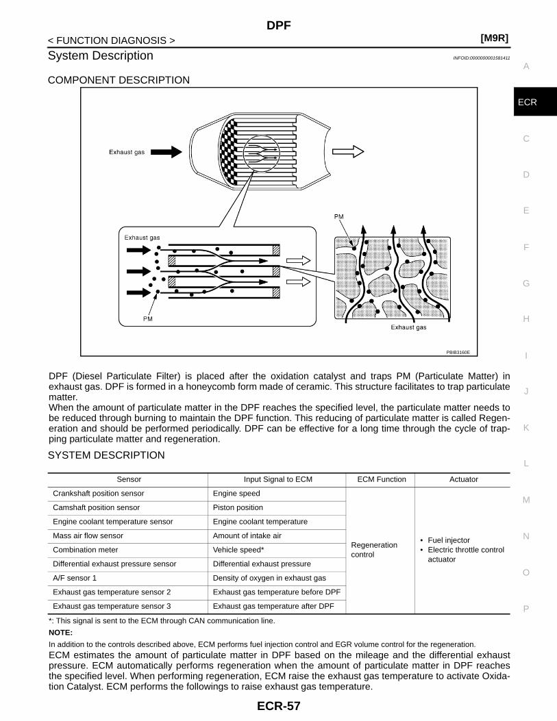
DPF[M9R]
C
D
E
F
G
H
I
J
K
L
M
A
CR
N
P
O
< FUNCTION DIAGNOSIS >
E
System Description INFOID:0000000001581411
COMPONENT DESCRIPTION
DPF (Diesel Particulate Filter) is placed after the oxidation catalyst and traps PM (Particulate Matter) inexhaust gas. DPF is formed in a honeycomb form made of ceramic. This structure facilitates to trap particulatematter.When the amount of particulate matter in the DPF reaches the specified level, the particulate matter needs tobe reduced through burning to maintain the DPF function. This reducing of particulate matter is called Regen-eration and should be performed periodically. DPF can be effective for a long time through the cycle of trap-ping particulate matter and regeneration.
SYSTEM DESCRIPTION
*: This signal is sent to the ECM through CAN communication line.
NOTE:
In addition to the controls described above, ECM performs fuel injection control and EGR volume control for the regeneration.
ECM estimates the amount of particulate matter in DPF based on the mileage and the differential exhaustpressure. ECM automatically performs regeneration when the amount of particulate matter in DPF reachesthe specified level. When performing regeneration, ECM raise the exhaust gas temperature to activate Oxida-tion Catalyst. ECM performs the followings to raise exhaust gas temperature.
PBIB3160E
Sensor Input Signal to ECM ECM Function Actuator
Crankshaft position sensor Engine speed
Regeneration control
• Fuel injector• Electric throttle control
actuator
Camshaft position sensor Piston position
Engine coolant temperature sensor Engine coolant temperature
Mass air flow sensor Amount of intake air
Combination meter Vehicle speed*
Differential exhaust pressure sensor Differential exhaust pressure
A/F sensor 1 Density of oxygen in exhaust gas
Exhaust gas temperature sensor 2 Exhaust gas temperature before DPF
Exhaust gas temperature sensor 3 Exhaust gas temperature after DPF
ECR-57
[M9R]DPF
< FUNCTION DIAGNOSIS >• Closing throttle valve to reduce intake air volume• Retarding fuel injection timing• Injecting additional fuel into combustion chamber during exhaust stroke (post injection)• Performing EGR controlWhen exhaust gas temperature reaches the specified value, oxidation catalyst is activated. The trapped par-ticulate matter is burned through a catalytic reaction using exhaust gas heat at 600 °C.During regeneration ECM performs a feedback control to keep emission levels low and burn particulate mattersafely and efficiently. This feedback control is performed based on the air fuel mixture ratio and the exhaustgas temperature.When performing regeneration, ECM raise the exhaust gas tempera-ture to activate Oxidation Catalyst. If the vehicle is driven in the driv-ing pattern in which the exhaust gas temperature can not be raised,DPF warning light as shown in the figure lights up. DPF warning lightis located on combination meter.When DPF warning light lights up, drive the vehicle under any of thefollowing condition to complete regeneration.• The vehicle is driven continuously at 60km/h for 30 minutes*• The vehicle is driven continuously 15km or more without being
caught in traffic jamIf the vehicle is driven in the driving pattern in which the exhaust gastemperature can not be raised after DPF warning light lights up,ECM performs the following to protect DPF.• ECM enters fail-safe mode and limits engine speed to 3,000 rpm with fuel cut.• ECM stores DTC P2002 in the memory.To recover from the condition described above, perform “Service Regeneration” with CONSULT-III to reducethe particulate matter through burning. Refer to ECR-16, "SERVICE REGENERATION : Description".*: Always drive vehicle in safe manner according to traffic conditions and obey all traffic laws when driving.
PBIB3166E
ECR-58
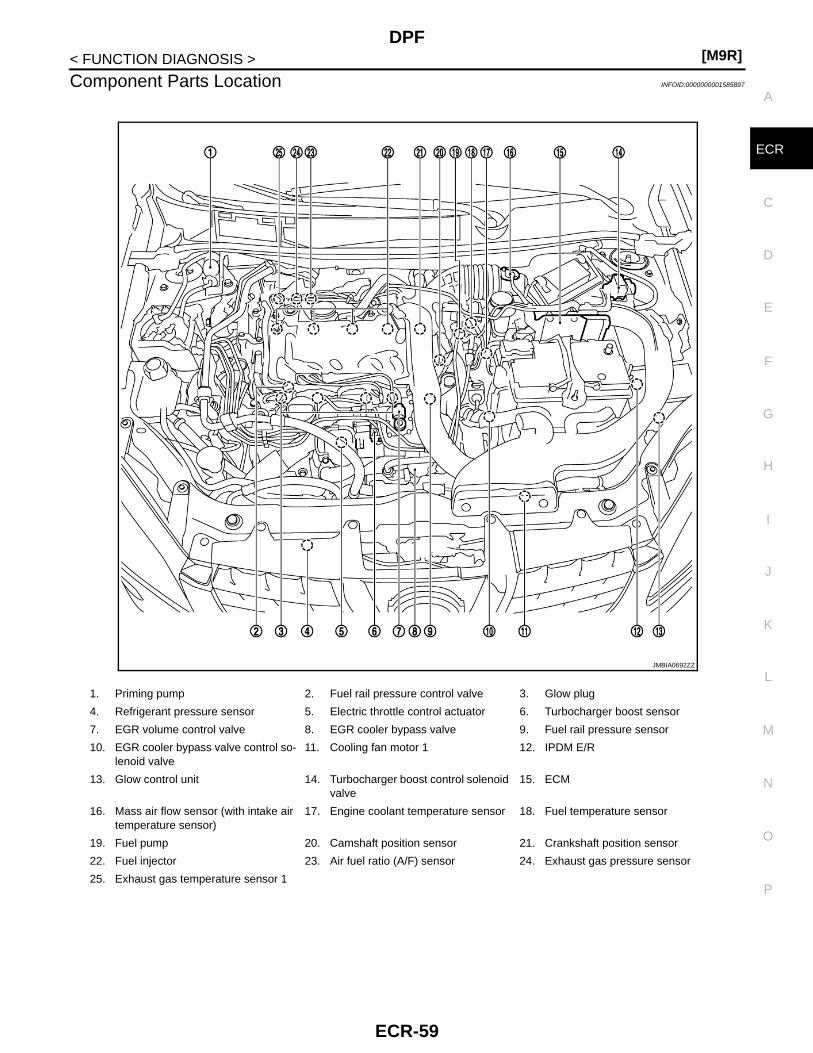
DPF[M9R]
C
D
E
F
G
H
I
J
K
L
M
A
CR
N
P
O
< FUNCTION DIAGNOSIS >
E
Component Parts Location INFOID:0000000001585897
1. Priming pump 2. Fuel rail pressure control valve 3. Glow plug
4. Refrigerant pressure sensor 5. Electric throttle control actuator 6. Turbocharger boost sensor
7. EGR volume control valve 8. EGR cooler bypass valve 9. Fuel rail pressure sensor
10. EGR cooler bypass valve control so-lenoid valve
11. Cooling fan motor 1 12. IPDM E/R
13. Glow control unit 14. Turbocharger boost control solenoid valve
15. ECM
16. Mass air flow sensor (with intake air temperature sensor)
17. Engine coolant temperature sensor 18. Fuel temperature sensor
19. Fuel pump 20. Camshaft position sensor 21. Crankshaft position sensor
22. Fuel injector 23. Air fuel ratio (A/F) sensor 24. Exhaust gas pressure sensor
25. Exhaust gas temperature sensor 1
JMBIA0692ZZ
ECR-59
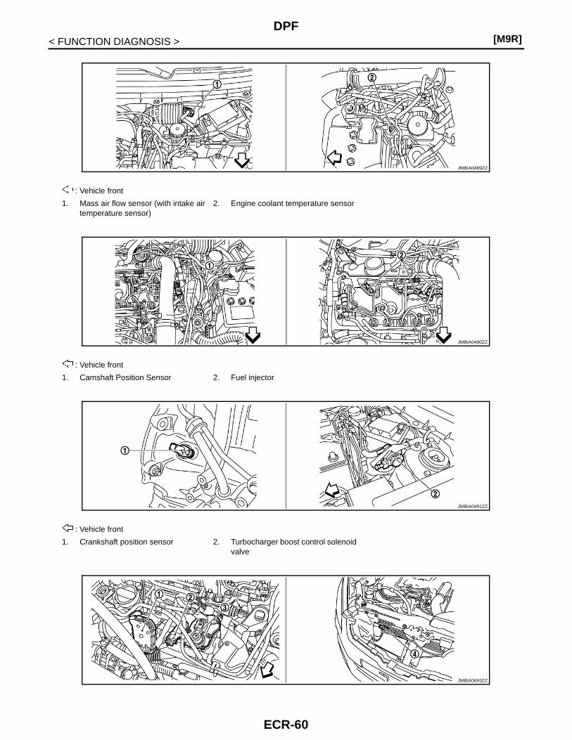
[M9R]DPF
< FUNCTION DIAGNOSIS >
: Vehicle front
1. Mass air flow sensor (with intake air temperature sensor)
2. Engine coolant temperature sensor
: Vehicle front
1. Camshaft Position Sensor 2. Fuel injector
: Vehicle front
1. Crankshaft position sensor 2. Turbocharger boost control solenoid valve
JMBIA0489ZZ
JMBIA0490ZZ
JMBIA0491ZZ
JMBIA0693ZZ
ECR-60

DPF[M9R]
C
D
E
F
G
H
I
J
K
L
M
A
CR
N
P
O
< FUNCTION DIAGNOSIS >
E
: Vehicle front
1. Electric throttle control actuator 2. Turbocharger boost sensor 3. EGR volume control valve
4. Refrigerant pressure sensor
: Vehicle front
1. Fuel rail pressure sensor 2. Fuel rail pressure control valve
: Vehicle front
1. Fuel temperature sensor 2. Fuel pump 3. EGR cooler bypass valve control so-lenoid valve
: Vehicle front
1. Exhaust gas temperature sensor 1 2. Exhaust gas pressure sensor 3. Air fuel ratio (A/F) sensor
JMBIA0493ZZ
JMBIA0494ZZ
JMBIA0495ZZ
ECR-61

[M9R]DPF
< FUNCTION DIAGNOSIS >
: Vehicle front
1. Differential exhaust pressure sensor 2. Turbocharger cooling pump 3. Exhaust gas temperature sensor 3
4. Exhaust gas temperature sensor 2
: Vehicle front
1. Glow control unit 2. Glow plug
1. Accelerator pedal position sensor 2. Stop lamp switch 3. Shift lock brake switch
: Vehicle front
1. Clutch pedal position switch 2. ECM
JMBIA0496ZZ
JMBIA0497ZZ
JMBIA0498ZZ
JMBIA0499ZZ
ECR-62

DPF[M9R]
C
D
E
F
G
H
I
J
K
L
M
A
CR
N
P
O
< FUNCTION DIAGNOSIS >
E
Component Description INFOID:0000000001581413
1. ASDC steering switch 2. CANSEL switch 3. RESUME/ACCCELERATE switch
4. SET/COAST switch 5. MAIN SWITCH
JMBIA0483ZZ
Component Reference
A/F sensor 1 ECR-137, "Description"
Camshaft position sensor ECR-169, "Description"
Crankshaft position sensor ECR-167, "Description"
Differential exhaust pressure sensor ECR-268, "Description"
Engine coolant temperature sensor ECR-132, "Description"
Exhaust gas temperature sensor 2 ECR-231, "Description"
Exhaust gas temperature sensor 3 ECR-263, "Description"
Fuel injector ECR-155, "Description"
Mass air flow sensor ECR-123, "Description"
Throttle position sensor ECR-134, "Description"
Vehicle speed sensor ECR-184, "Description"
ECR-63

[M9R]EGR SYSTEM
< FUNCTION DIAGNOSIS >
EGR SYSTEM
System Description INFOID:0000000001581414
EGR VALVE CONTROL
System Diagram
System DescriptionINPUT/OUTPUT SIGNAL CHART
*: This signal is sent to the ECM through CAN communication line.
SYSTEM DESCRIPTIONThis system controls the flow rate of EGR led from exhaust manifold to intake manifold.The opening of the EGR passage in the EGR volume control valve changes to control the EGR flow rate.A built-in DC motor moves the valve continuously corresponding to the ECM output signal.The EGR volume control valve control position sensor detects the valve position and sends the voltage signalsto the ECM.The ECM judges the current opening angle of the valve from this signals and the ECM controls the DC motorto make the valve opening angle properly.
JMBIA0655GB
Sensor Input Signal to ECM ECM function Actuator
Crankshaft position sensor Engine speed
EGR volume controlEGR volume con-trol valve
Engine coolant temperature sensor Engine coolant temperature
Intake air temperature sensor Intake air temperature
Mass air flow sensor Amount of intake air
Accelerator pedal position sensor Accelerator pedal position
Ignition switch Start signal
EGR volume control valve control position sensor
EGR volume control valve control position
Barometric pressure sensor Barometric pressure
Vehicle speed sensor Vehicle speed*
Air conditioner switch Air conditioner operation*
ECR-64

EGR SYSTEM[M9R]
C
D
E
F
G
H
I
J
K
L
M
A
CR
N
P
O
< FUNCTION DIAGNOSIS >
E
The opening angle of the valve varies for optimum engine control. The optimum value stored in the ECM isdetermined b7y considering various engine conditions.The EGR volume control valve remains close under the following conditions.• Engine stopped• Engine starting• Low engine coolant temperature• Excessively high engine coolant temperature• High engine speed• Accelerator pedal fully depressed
EGR COOLER BYPASS CONTROL
System Diagram
VACUUM HOSE DRAWINGJMBIA0656GB
JMBIA0554ZZ
ECR-65

[M9R]EGR SYSTEM
< FUNCTION DIAGNOSIS >
System DescriptionINPUT/OUTPUT SIGNAL CHART
SYSTEM DESCRIPTIONECM controls the bypass gas volume to EGR cooler at engine cold.EGR cooler bypass valve control solenoid valve controls the vacuum signal to EGR cooler bypass valve con-trol actuator.ERG amount is controlled by changing the EGR cooler bypass valve opening using the rod.EGR cooler bypass valve control solenoid valve is operated by ON/OFF signals (pulse signals) sent fromECM. The longer is the ON pulse duration, the larger becomes the bypass gas volume.
Component Parts Location INFOID:0000000001585898
1. Turbocharger boost control actuator 2. EGR cooler bypass valve control so-lenoid valve
3. Vacuum pump
4. Turbocharger boost control solenoid valve
Sensor Input Signal to ECM ECM function Actuator
Engine coolant temperature sensor Engine coolant temperature EGR cooler bypass control
EGR cooler bypass valve control solenoid valveCrankshaft position sensor Engine speed
JMBIA0692ZZ
ECR-66

EGR SYSTEM[M9R]
C
D
E
F
G
H
I
J
K
L
M
A
CR
N
P
O
< FUNCTION DIAGNOSIS >
E
1. Priming pump 2. Fuel rail pressure control valve 3. Glow plug
4. Refrigerant pressure sensor 5. Electric throttle control actuator 6. Turbocharger boost sensor
7. EGR volume control valve 8. EGR cooler bypass valve 9. Fuel rail pressure sensor
10. EGR cooler bypass valve control so-lenoid valve
11. Cooling fan motor 1 12. IPDM E/R
13. Glow control unit 14. Turbocharger boost control solenoid valve
15. ECM
16. Mass air flow sensor (with intake air temperature sensor)
17. Engine coolant temperature sensor 18. Fuel temperature sensor
19. Fuel pump 20. Camshaft position sensor 21. Crankshaft position sensor
22. Fuel injector 23. Air fuel ratio (A/F) sensor 24. Exhaust gas pressure sensor
25. Exhaust gas temperature sensor 1
: Vehicle front
1. Mass air flow sensor (with intake air temperature sensor)
2. Engine coolant temperature sensor
: Vehicle front
1. Camshaft Position Sensor 2. Fuel injector
JMBIA0489ZZ
JMBIA0490ZZ
JMBIA0491ZZ
: Vehicle front
1. Crankshaft position sensor 2. Turbocharger boost control solenoid valve
ECR-67

[M9R]EGR SYSTEM
< FUNCTION DIAGNOSIS >
: Vehicle front
1. Electric throttle control actuator 2. Turbocharger boost sensor 3. EGR volume control valve
4. Refrigerant pressure sensor
: Vehicle front
1. Fuel rail pressure sensor 2. Fuel rail pressure control valve
: Vehicle front
1. Fuel temperature sensor 2. Fuel pump 3. EGR cooler bypass valve control so-lenoid valve
JMBIA0693ZZ
JMBIA0493ZZ
JMBIA0494ZZ
JMBIA0495ZZ
ECR-68

EGR SYSTEM[M9R]
C
D
E
F
G
H
I
J
K
L
M
A
CR
N
P
O
< FUNCTION DIAGNOSIS >
E
: Vehicle front
1. Exhaust gas temperature sensor 1 2. Exhaust gas pressure sensor 3. Air fuel ratio (A/F) sensor
: Vehicle front
1. Differential exhaust pressure sensor 2. Turbocharger cooling pump 3. Exhaust gas temperature sensor 3
4. Exhaust gas temperature sensor 2
: Vehicle front
1. Glow control unit 2. Glow plug
1. Accelerator pedal position sensor 2. Stop lamp switch 3. Shift lock brake switch
JMBIA0496ZZ
JMBIA0497ZZ
JMBIA0498ZZ
JMBIA0499ZZ
ECR-69

[M9R]EGR SYSTEM
< FUNCTION DIAGNOSIS >
Component Description INFOID:0000000001581416
: Vehicle front
1. Clutch pedal position switch 2. ECM
1. ASDC steering switch 2. CANSEL switch 3. RESUME/ACCCELERATE switch
4. SET/COAST switch 5. MAIN SWITCH
JMBIA0483ZZ
Component Reference
Accelerator pedal position sensor ECR-158, "Description"
Barometric pressure sensor ECR-247, "Description"
Crankshaft position sensor ECR-167, "Description"
EGR cooler bypass valve control solenoid valve ECR-261, "Description"
EGR volume control valve ECR-180, "Description"
EGR volume control valve control position sensor ECR-175, "Description"
Engine coolant temperature sensor ECR-132, "Description"
Intake air temperature sensor ECR-130, "Description"
Mass air flow sensor ECR-123, "Description"
Vehicle speed sensor ECR-184, "Description"
ECR-70
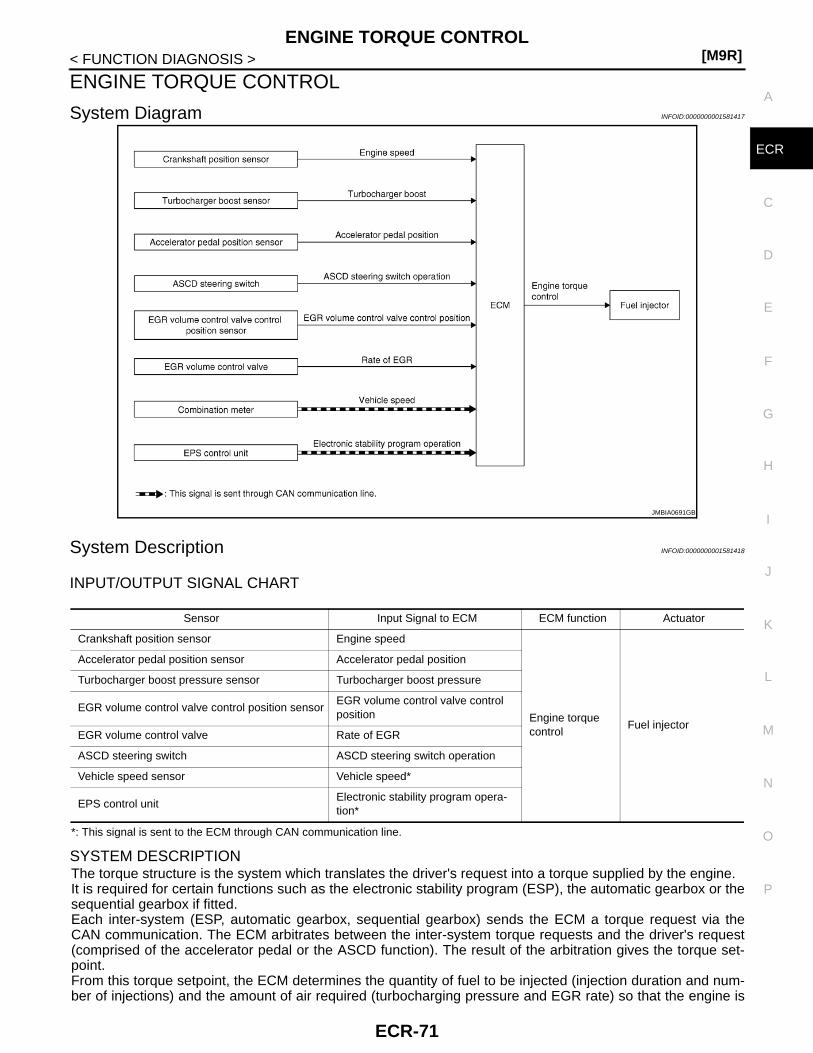
ENGINE TORQUE CONTROL[M9R]
C
D
E
F
G
H
I
J
K
L
M
A
CR
N
P
O
< FUNCTION DIAGNOSIS >
E
ENGINE TORQUE CONTROL
System Diagram INFOID:0000000001581417
System Description INFOID:0000000001581418
INPUT/OUTPUT SIGNAL CHART
*: This signal is sent to the ECM through CAN communication line.
SYSTEM DESCRIPTIONThe torque structure is the system which translates the driver's request into a torque supplied by the engine.It is required for certain functions such as the electronic stability program (ESP), the automatic gearbox or thesequential gearbox if fitted.Each inter-system (ESP, automatic gearbox, sequential gearbox) sends the ECM a torque request via theCAN communication. The ECM arbitrates between the inter-system torque requests and the driver's request(comprised of the accelerator pedal or the ASCD function). The result of the arbitration gives the torque set-point.From this torque setpoint, the ECM determines the quantity of fuel to be injected (injection duration and num-ber of injections) and the amount of air required (turbocharging pressure and EGR rate) so that the engine is
JMBIA0691GB
Sensor Input Signal to ECM ECM function Actuator
Crankshaft position sensor Engine speed
Engine torque control
Fuel injector
Accelerator pedal position sensor Accelerator pedal position
Turbocharger boost pressure sensor Turbocharger boost pressure
EGR volume control valve control position sensorEGR volume control valve control position
EGR volume control valve Rate of EGR
ASCD steering switch ASCD steering switch operation
Vehicle speed sensor Vehicle speed*
EPS control unitElectronic stability program opera-tion*
ECR-71

[M9R]ENGINE TORQUE CONTROL
< FUNCTION DIAGNOSIS >able to provide the torque required in the best possible conditions (in terms of smooth running performance,pollutant emissions, etc.).
Component Parts Location INFOID:0000000001585899
1. Priming pump 2. Fuel rail pressure control valve 3. Glow plug
4. Refrigerant pressure sensor 5. Electric throttle control actuator 6. Turbocharger boost sensor
7. EGR volume control valve 8. EGR cooler bypass valve 9. Fuel rail pressure sensor
10. EGR cooler bypass valve control so-lenoid valve
11. Cooling fan motor 1 12. IPDM E/R
13. Glow control unit 14. Turbocharger boost control solenoid valve
15. ECM
16. Mass air flow sensor (with intake air temperature sensor)
17. Engine coolant temperature sensor 18. Fuel temperature sensor
19. Fuel pump 20. Camshaft position sensor 21. Crankshaft position sensor
22. Fuel injector 23. Air fuel ratio (A/F) sensor 24. Exhaust gas pressure sensor
25. Exhaust gas temperature sensor 1
JMBIA0692ZZ
ECR-72

ENGINE TORQUE CONTROL[M9R]
C
D
E
F
G
H
I
J
K
L
M
A
CR
N
P
O
< FUNCTION DIAGNOSIS >
E
: Vehicle front
1. Mass air flow sensor (with intake air temperature sensor)
2. Engine coolant temperature sensor
: Vehicle front
1. Camshaft Position Sensor 2. Fuel injector
: Vehicle front
1. Crankshaft position sensor 2. Turbocharger boost control solenoid valve
JMBIA0489ZZ
JMBIA0490ZZ
JMBIA0491ZZ
JMBIA0693ZZ
ECR-73

[M9R]ENGINE TORQUE CONTROL
< FUNCTION DIAGNOSIS >
: Vehicle front
1. Electric throttle control actuator 2. Turbocharger boost sensor 3. EGR volume control valve
4. Refrigerant pressure sensor
: Vehicle front
1. Fuel rail pressure sensor 2. Fuel rail pressure control valve
: Vehicle front
1. Fuel temperature sensor 2. Fuel pump 3. EGR cooler bypass valve control so-lenoid valve
: Vehicle front
1. Exhaust gas temperature sensor 1 2. Exhaust gas pressure sensor 3. Air fuel ratio (A/F) sensor
JMBIA0493ZZ
JMBIA0494ZZ
JMBIA0495ZZ
ECR-74

ENGINE TORQUE CONTROL[M9R]
C
D
E
F
G
H
I
J
K
L
M
A
CR
N
P
O
< FUNCTION DIAGNOSIS >
E
: Vehicle front
1. Differential exhaust pressure sensor 2. Turbocharger cooling pump 3. Exhaust gas temperature sensor 3
4. Exhaust gas temperature sensor 2
: Vehicle front
1. Glow control unit 2. Glow plug
1. Accelerator pedal position sensor 2. Stop lamp switch 3. Shift lock brake switch
: Vehicle front
1. Clutch pedal position switch 2. ECM
JMBIA0496ZZ
JMBIA0497ZZ
JMBIA0498ZZ
JMBIA0499ZZ
ECR-75
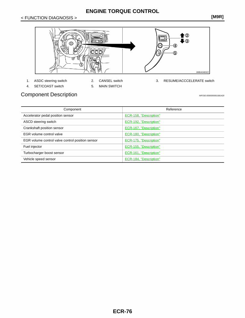
[M9R]ENGINE TORQUE CONTROL
< FUNCTION DIAGNOSIS >
Component Description INFOID:0000000001581420
1. ASDC steering switch 2. CANSEL switch 3. RESUME/ACCCELERATE switch
4. SET/COAST switch 5. MAIN SWITCH
JMBIA0483ZZ
Component Reference
Accelerator pedal position sensor ECR-158, "Description"
ASCD steering switch ECR-192, "Description"
Crankshaft position sensor ECR-167, "Description"
EGR volume control valve ECR-180, "Description"
EGR volume control valve control position sensor ECR-175, "Description"
Fuel injector ECR-155, "Description"
Turbocharger boost sensor ECR-161, "Description"
Vehicle speed sensor ECR-184, "Description"
ECR-76

GLOW CONTROL[M9R]
C
D
E
F
G
H
I
J
K
L
M
A
CR
N
P
O
< FUNCTION DIAGNOSIS >
E
GLOW CONTROL
System Diagram INFOID:0000000001581421
System Description INFOID:0000000001581422
INPUT/OUTPUT SIGNAL CHART
SYSTEM DESCRIPTIONWhen ignition switch is turned ON while cooling temperature is lower than the specified value, ECM actuatesglow plug through glow control unit. Because of this, combustion chamber is warmed and stabilized combus-tion at starting can be obtained under low cooling temperature. The preheating time is determined accordingto cooling temperature, inlet air temperature and battery voltage.
JMBIA0657GB
Sensor Input Signal to ECM ECM function Actuator
Engine coolant temperature sensor Engine coolant temperature
Glow controlGrow control unit↓Glow plug
Intake air temperature sensor Intake air temperature
Battery Battery voltage
Barometric pressure sensor Barometric pressure
ECR-77
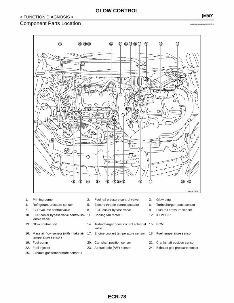
[M9R]GLOW CONTROL
< FUNCTION DIAGNOSIS >
Component Parts Location INFOID:0000000001585900
1. Priming pump 2. Fuel rail pressure control valve 3. Glow plug
4. Refrigerant pressure sensor 5. Electric throttle control actuator 6. Turbocharger boost sensor
7. EGR volume control valve 8. EGR cooler bypass valve 9. Fuel rail pressure sensor
10. EGR cooler bypass valve control so-lenoid valve
11. Cooling fan motor 1 12. IPDM E/R
13. Glow control unit 14. Turbocharger boost control solenoid valve
15. ECM
16. Mass air flow sensor (with intake air temperature sensor)
17. Engine coolant temperature sensor 18. Fuel temperature sensor
19. Fuel pump 20. Camshaft position sensor 21. Crankshaft position sensor
22. Fuel injector 23. Air fuel ratio (A/F) sensor 24. Exhaust gas pressure sensor
25. Exhaust gas temperature sensor 1
JMBIA0692ZZ
ECR-78
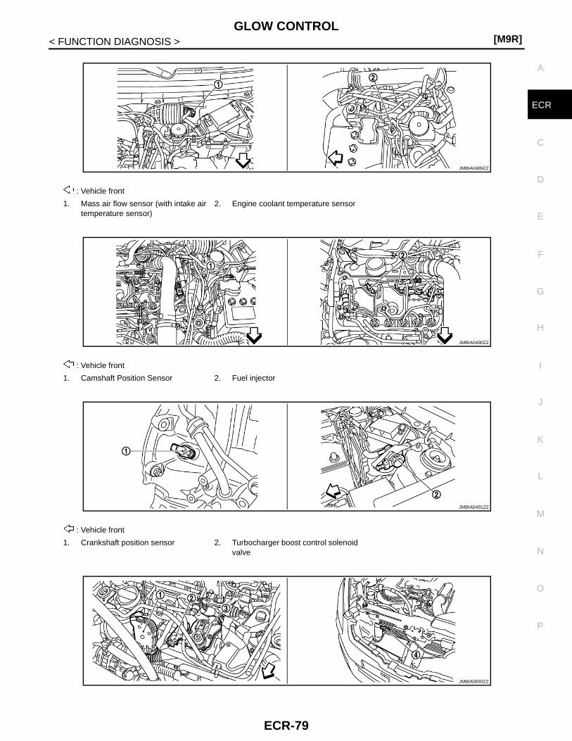
GLOW CONTROL[M9R]
C
D
E
F
G
H
I
J
K
L
M
A
CR
N
P
O
< FUNCTION DIAGNOSIS >
E
: Vehicle front
1. Mass air flow sensor (with intake air temperature sensor)
2. Engine coolant temperature sensor
: Vehicle front
1. Camshaft Position Sensor 2. Fuel injector
: Vehicle front
1. Crankshaft position sensor 2. Turbocharger boost control solenoid valve
JMBIA0489ZZ
JMBIA0490ZZ
JMBIA0491ZZ
JMBIA0693ZZ
ECR-79

[M9R]GLOW CONTROL
< FUNCTION DIAGNOSIS >
: Vehicle front
1. Electric throttle control actuator 2. Turbocharger boost sensor 3. EGR volume control valve
4. Refrigerant pressure sensor
: Vehicle front
1. Fuel rail pressure sensor 2. Fuel rail pressure control valve
: Vehicle front
1. Fuel temperature sensor 2. Fuel pump 3. EGR cooler bypass valve control so-lenoid valve
: Vehicle front
1. Exhaust gas temperature sensor 1 2. Exhaust gas pressure sensor 3. Air fuel ratio (A/F) sensor
JMBIA0493ZZ
JMBIA0494ZZ
JMBIA0495ZZ
ECR-80

GLOW CONTROL[M9R]
C
D
E
F
G
H
I
J
K
L
M
A
CR
N
P
O
< FUNCTION DIAGNOSIS >
E
: Vehicle front
1. Differential exhaust pressure sensor 2. Turbocharger cooling pump 3. Exhaust gas temperature sensor 3
4. Exhaust gas temperature sensor 2
: Vehicle front
1. Glow control unit 2. Glow plug
1. Accelerator pedal position sensor 2. Stop lamp switch 3. Shift lock brake switch
: Vehicle front
1. Clutch pedal position switch 2. ECM
JMBIA0496ZZ
JMBIA0497ZZ
JMBIA0498ZZ
JMBIA0499ZZ
ECR-81

[M9R]GLOW CONTROL
< FUNCTION DIAGNOSIS >
Component Description INFOID:0000000001581424
1. ASDC steering switch 2. CANSEL switch 3. RESUME/ACCCELERATE switch
4. SET/COAST switch 5. MAIN SWITCH
JMBIA0483ZZ
Component Reference
Barometric pressure sensor ECR-247, "Description"
Engine coolant temperature sensor ECR-132, "Description"
Intake air temperature sensor ECR-130, "Description"
ECR-82

IDLE SPEED CONTROL[M9R]
C
D
E
F
G
H
I
J
K
L
M
A
CR
N
P
O
< FUNCTION DIAGNOSIS >
E
IDLE SPEED CONTROL
System Diagram INFOID:0000000001581425
System Description INFOID:0000000001581426
INPUT/OUTPUT SIGNAL CHART
*: This signal is sent to the ECM through CAN communication line.
SYSTEM DESCRIPTIONThe ECM is responsible for regulating the idle speed as a function of the idle speed setpoint which it calcu-lates.
JMBIA0660GB
Sensor Input Signal to ECM ECM function Actuator
Engine coolant temperature sensor Engine coolant temperature
Idle speed con-trol
Fuel injectorFuel pump
Battery Battery voltage
Headlamp switchLoad signal*
Rear defogger switch
EPS control unit Power steering operation*
Air conditioner switch Air conditioner operation*
ECR-83

[M9R]IDLE SPEED CONTROL
< FUNCTION DIAGNOSIS >
Component Parts Location INFOID:0000000001585901
1. Priming pump 2. Fuel rail pressure control valve 3. Glow plug
4. Refrigerant pressure sensor 5. Electric throttle control actuator 6. Turbocharger boost sensor
7. EGR volume control valve 8. EGR cooler bypass valve 9. Fuel rail pressure sensor
10. EGR cooler bypass valve control so-lenoid valve
11. Cooling fan motor 1 12. IPDM E/R
13. Glow control unit 14. Turbocharger boost control solenoid valve
15. ECM
16. Mass air flow sensor (with intake air temperature sensor)
17. Engine coolant temperature sensor 18. Fuel temperature sensor
19. Fuel pump 20. Camshaft position sensor 21. Crankshaft position sensor
22. Fuel injector 23. Air fuel ratio (A/F) sensor 24. Exhaust gas pressure sensor
25. Exhaust gas temperature sensor 1
JMBIA0692ZZ
ECR-84

IDLE SPEED CONTROL[M9R]
C
D
E
F
G
H
I
J
K
L
M
A
CR
N
P
O
< FUNCTION DIAGNOSIS >
E
: Vehicle front
1. Mass air flow sensor (with intake air temperature sensor)
2. Engine coolant temperature sensor
: Vehicle front
1. Camshaft Position Sensor 2. Fuel injector
: Vehicle front
1. Crankshaft position sensor 2. Turbocharger boost control solenoid valve
JMBIA0489ZZ
JMBIA0490ZZ
JMBIA0491ZZ
JMBIA0693ZZ
ECR-85

[M9R]IDLE SPEED CONTROL
< FUNCTION DIAGNOSIS >
: Vehicle front
1. Electric throttle control actuator 2. Turbocharger boost sensor 3. EGR volume control valve
4. Refrigerant pressure sensor
: Vehicle front
1. Fuel rail pressure sensor 2. Fuel rail pressure control valve
: Vehicle front
1. Fuel temperature sensor 2. Fuel pump 3. EGR cooler bypass valve control so-lenoid valve
: Vehicle front
1. Exhaust gas temperature sensor 1 2. Exhaust gas pressure sensor 3. Air fuel ratio (A/F) sensor
JMBIA0493ZZ
JMBIA0494ZZ
JMBIA0495ZZ
ECR-86

IDLE SPEED CONTROL[M9R]
C
D
E
F
G
H
I
J
K
L
M
A
CR
N
P
O
< FUNCTION DIAGNOSIS >
E
: Vehicle front
1. Differential exhaust pressure sensor 2. Turbocharger cooling pump 3. Exhaust gas temperature sensor 3
4. Exhaust gas temperature sensor 2
: Vehicle front
1. Glow control unit 2. Glow plug
1. Accelerator pedal position sensor 2. Stop lamp switch 3. Shift lock brake switch
: Vehicle front
1. Clutch pedal position switch 2. ECM
JMBIA0496ZZ
JMBIA0497ZZ
JMBIA0498ZZ
JMBIA0499ZZ
ECR-87

[M9R]IDLE SPEED CONTROL
< FUNCTION DIAGNOSIS >
Component Description INFOID:0000000001581428
1. ASDC steering switch 2. CANSEL switch 3. RESUME/ACCCELERATE switch
4. SET/COAST switch 5. MAIN SWITCH
JMBIA0483ZZ
Component Reference
Engine coolant temperature sensor ECR-132, "Description"
Fuel injector ECR-155, "Description"
ECR-88

TURBOCHARGER BOOST CONTROL[M9R]
C
D
E
F
G
H
I
J
K
L
M
A
CR
N
P
O
< FUNCTION DIAGNOSIS >
E
TURBOCHARGER BOOST CONTROL
System Description INFOID:0000000001581429
TURBOCHARGER BOOST CONTROL
System Diagram
VACUUM HOSE DRAWINGJMBIA0653GB
ECR-89

[M9R]TURBOCHARGER BOOST CONTROL
< FUNCTION DIAGNOSIS >
System DescriptionINPUT/OUTPUT SIGNAL CHART
SYSTEM DESCRIPTIONTurbocharger boost control solenoid valve is operated by ON/OFF signals (pulse signals) from ECM.Output signal to turbocharger boost control solenoid valve is feedback controlled to obtain the optimum boostpressure so that the amount of intake air detected by mas air flow sensor is equal to the target amountdecided by engine revolution and injected amount of fuel.Under the driving condition of increasing boost pressure, ON time rate of turbocharger boost control solenoidvalve is increased by ECM signal to shift the nozzle vane in closing direction. Under the driving condition ofdecreasing boost pressure, ON time rate of turbocharger boost control solenoid valve is decreased by ECMsignal to shift the nozzle vane in opening direction.
1. Turbocharger boost control actuator 2. EGR cooler bypass valve control so-lenoid valve
3. Vacuum pump
4. Turbocharger boost control solenoid valve
JMBIA0554ZZ
Sensor Input Signal to ECM ECM function Actuator
Mass air flow sensor Amount of intake air
Turbocharger boost control
Turbocharger boost control solenoid valve↓Turbocharger boost control actuator
Crankshaft position sensor Engine speed
Intake air temperature sensor Intake air temperature
Accelerator pedal position sensor Accelerator pedal position
Fuel rail pressure sensor Fuel rail pressure
Turbocharger boost sensor Turbocharger boost
Exhaust gas pressure sensor Exhaust gas pressure
Exhaust gas temperature sensor 1 Exhaust gas temperature
ECR-90

TURBOCHARGER BOOST CONTROL[M9R]
C
D
E
F
G
H
I
J
K
L
M
A
CR
N
P
O
< FUNCTION DIAGNOSIS >
E
TURBOCHARGER COOLING CONTROL
System Diagram
System DescriptionINPUT/OUTPUT SIGNAL CHART
SYSTEM DESCRIPTIONTo prevent high oil temperature around turbine bearing, cooling water is circulated around the bearing usingturbocharger cooling pump.Excessively high oil temperature causes the change of oil viscosity property resulting in bearing seizure.Therefore, ECM actuates the cooling pump when the cooling water temperature exceeds the specified value.
JMBIA0654GB
Sensor Input Signal to ECM ECM function Actuator
Engine coolant temperature sensor Engine coolant temperature
Turbocharger cooling control
Turbocharger cooling pump relay↓Turbocharger cooling pump
Crankshaft position sensor Engine speed
ECR-91

[M9R]TURBOCHARGER BOOST CONTROL
< FUNCTION DIAGNOSIS >
Component Parts Location INFOID:0000000001585902
1. Priming pump 2. Fuel rail pressure control valve 3. Glow plug
4. Refrigerant pressure sensor 5. Electric throttle control actuator 6. Turbocharger boost sensor
7. EGR volume control valve 8. EGR cooler bypass valve 9. Fuel rail pressure sensor
10. EGR cooler bypass valve control so-lenoid valve
11. Cooling fan motor 1 12. IPDM E/R
13. Glow control unit 14. Turbocharger boost control solenoid valve
15. ECM
16. Mass air flow sensor (with intake air temperature sensor)
17. Engine coolant temperature sensor 18. Fuel temperature sensor
19. Fuel pump 20. Camshaft position sensor 21. Crankshaft position sensor
22. Fuel injector 23. Air fuel ratio (A/F) sensor 24. Exhaust gas pressure sensor
25. Exhaust gas temperature sensor 1
JMBIA0692ZZ
ECR-92

TURBOCHARGER BOOST CONTROL[M9R]
C
D
E
F
G
H
I
J
K
L
M
A
CR
N
P
O
< FUNCTION DIAGNOSIS >
E
: Vehicle front
1. Mass air flow sensor (with intake air temperature sensor)
2. Engine coolant temperature sensor
: Vehicle front
1. Camshaft Position Sensor 2. Fuel injector
: Vehicle front
1. Crankshaft position sensor 2. Turbocharger boost control solenoid valve
JMBIA0489ZZ
JMBIA0490ZZ
JMBIA0491ZZ
JMBIA0693ZZ
ECR-93
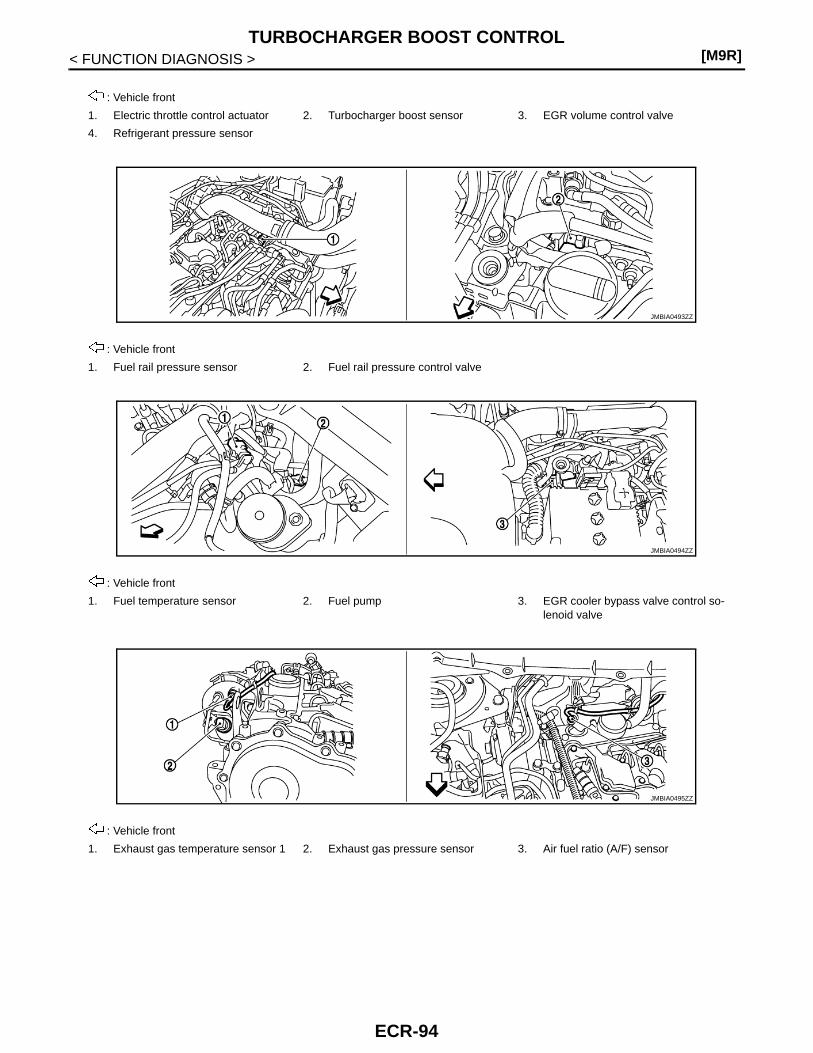
[M9R]TURBOCHARGER BOOST CONTROL
< FUNCTION DIAGNOSIS >
: Vehicle front
1. Electric throttle control actuator 2. Turbocharger boost sensor 3. EGR volume control valve
4. Refrigerant pressure sensor
: Vehicle front
1. Fuel rail pressure sensor 2. Fuel rail pressure control valve
: Vehicle front
1. Fuel temperature sensor 2. Fuel pump 3. EGR cooler bypass valve control so-lenoid valve
: Vehicle front
1. Exhaust gas temperature sensor 1 2. Exhaust gas pressure sensor 3. Air fuel ratio (A/F) sensor
JMBIA0493ZZ
JMBIA0494ZZ
JMBIA0495ZZ
ECR-94

TURBOCHARGER BOOST CONTROL[M9R]
C
D
E
F
G
H
I
J
K
L
M
A
CR
N
P
O
< FUNCTION DIAGNOSIS >
E
: Vehicle front
1. Differential exhaust pressure sensor 2. Turbocharger cooling pump 3. Exhaust gas temperature sensor 3
4. Exhaust gas temperature sensor 2
: Vehicle front
1. Glow control unit 2. Glow plug
1. Accelerator pedal position sensor 2. Stop lamp switch 3. Shift lock brake switch
: Vehicle front
1. Clutch pedal position switch 2. ECM
JMBIA0496ZZ
JMBIA0497ZZ
JMBIA0498ZZ
JMBIA0499ZZ
ECR-95

[M9R]TURBOCHARGER BOOST CONTROL
< FUNCTION DIAGNOSIS >
Component Description INFOID:0000000001581431
1. ASDC steering switch 2. CANSEL switch 3. RESUME/ACCCELERATE switch
4. SET/COAST switch 5. MAIN SWITCH
JMBIA0483ZZ
Component Reference
Accelerator pedal position sensor ECR-158, "Description"
Crankshaft position sensor ECR-167, "Description"
Engine coolant temperature sensor ECR-132, "Description"
Exhaust gas pressure sensor ECR-178, "Description"
Exhaust gas temperature sensor 1 ECR-187, "Description"
Fuel rail pressure sensor ECR-150, "Description"
Intake air temperature sensor ECR-130, "Description"
Mass air flow sensor ECR-123, "Description"
Turbocharger boost control solenoid valve ECR-117, "Description"
Turbocharger boost sensor ECR-161, "Description"
Turbocharger cooling pump ECR-273, "Description"
ECR-96
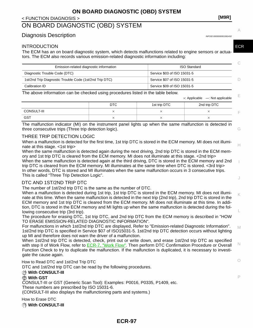
ON BOARD DIAGNOSTIC (OBD) SYSTEM[M9R]
C
D
E
F
G
H
I
J
K
L
M
A
CR
N
P
O
< FUNCTION DIAGNOSIS >
E
ON BOARD DIAGNOSTIC (OBD) SYSTEM
Diagnosis Description INFOID:0000000001581432
INTRODUCTIONThe ECM has an on board diagnostic system, which detects malfunctions related to engine sensors or actua-tors. The ECM also records various emission-related diagnostic information including:
The above information can be checked using procedures listed in the table below.×: Applicable —: Not applicable
The malfunction indicator (MI) on the instrument panel lights up when the same malfunction is detected inthree consecutive trips (Three trip detection logic).
THREE TRIP DETECTION LOGICWhen a malfunction is detected for the first time, 1st trip DTC is stored in the ECM memory. MI does not illumi-nate at this stage. <1st trip>When the same malfunction is detected again during the next driving, 2nd trip DTC is stored in the ECM mem-ory and 1st trip DTC is cleared from the ECM memory. MI does not illuminate at this stage. <2nd trip>When the same malfunction is detected again at the third driving, DTC is stored in the ECM memory and 2ndtrip DTC is cleared from the ECM memory. MI illuminates at the same time when DTC is stored. <3rd trip>In other words, DTC is stored and MI illuminates when the same malfunction occurs in 3 consecutive trips.This is called “Three Trip Detection Logic”.
DTC AND 1ST/2ND TRIP DTCThe number of 1st/2nd trip DTC is the same as the number of DTC.When a malfunction is detected during 1st trip, 1st trip DTC is stored in the ECM memory. MI does not illumi-nate at this time. When the same malfunction is detected in the next trip (2nd trip), 2nd trip DTC is stored in theECM memory and 1st trip DTC is cleared from the ECM memory. MI does not illuminate at this time. In addi-tion, DTC is stored in the ECM memory and MI lights up when the same malfunction is detected during the fol-lowing consecutive trip (3rd trip). The procedure for erasing DTC, 1st trip DTC, and 2nd trip DTC from the ECM memory is described in "HOWTO ERASE EMISSION-RELATED DIAGNOSTIC INFORMATION".For malfunctions in which 1st/2nd trip DTC are displayed, Refer to "Emission-related Diagnostic Information".1st/2nd trip DTC is specified in Service $07 of ISO15031-5. 1st/2nd trip DTC detection occurs without lightingup MI and therefore does not warn the driver of a malfunction.When 1st/2nd trip DTC is detected, check, print out or write down, and erase 1st/2nd trip DTC as specifiedwith step II of Work Flow, refer to ECR-7, "Work Flow". Then perform DTC Confirmation Procedure or OverallFunction Check to try to duplicate the malfunction. If the malfunction is duplicated, it is necessary to investi-gate the cause again.
How to Read DTC and 1st/2nd Trip DTCDTC and 1st/2nd trip DTC can be read by the following procedures.
With CONSULT-III With GST
CONSULT-III or GST (Generic Scan Tool): Examples: P0016, P0335, P1409, etc.These numbers are prescribed by ISO 15031-6.(CONSULT-III also displays the malfunctioning parts and systems.)
How to Erase DTC With CONSULT-III
Emission-related diagnostic information ISO Standard
Diagnostic Trouble Code (DTC) Service $03 of ISO 15031-5
1st/2nd Trip Diagnostic Trouble Code (1st/2nd Trip DTC) Service $07 of ISO 15031-5
Calibration ID Service $09 of ISO 15031-5
DTC 1st trip DTC 2nd trip DTC
CONSULT-III × × ×
GST × × ×
ECR-97

[M9R]ON BOARD DIAGNOSTIC (OBD) SYSTEM
< FUNCTION DIAGNOSIS >The emission related diagnostic information in the ECM can be erased by selecting “All Erase” in the Descrip-tion” of “FINAL CHECK” mode with CONSULT-III.
With GSTThe emission related diagnostic information in the ECM can be erased by selecting Service $04 with GST.1. If the ignition switch stays ON after repair work, be sure to turn ignition switch OFF once. Wait at least 30
seconds and then turn it ON (engine stopped) again.2. Select Service $04 with GST (Generic Scan Tool).• If the battery is disconnected, the emission-related diagnostic information will be lost within 24
hours.• The following data are cleared when the ECM memory is erased.- Diagnostic trouble codes- 1st trip diagnostic trouble codes- 2nd trip diagnostic trouble codesActual work procedures are explained using a DTC as an example. Be careful so that not only the DTC, but allof the data listed above, are cleared from the ECM memory during work procedures.
MALFUNCTION INDICATOR (MI)
DescriptionThe MI is located on the instrument panel.1. The MI will light up when the ignition switch is turned ON without
the engine running. This is a bulb check.2. When the engine is started, the MI should go off.
If the MI remains on, the on board diagnostic system hasdetected an engine system malfunction.
On Board Diagnostic System FunctionThe on board diagnostic system has the following three functions.
Diagnostic Test Mode I — Bulb CheckIn this mode, the MI on the instrument panel should stay ON. If it remains OFF, check the bulb.
Diagnostic Test Mode I — Malfunction Warning
OBD SYSTEM OPERATION CHART
SAT652J
Diagnostic Test Mode
KEY and ENG. Status
Function Explanation of Function
Mode I Ignition switch in ON position
Engine stopped
BULB CHECK This function checks the MI bulb for damage (blown, open circuit, etc.).If the MI does not come on, check MI circuit.
Engine running MALFUNCTIONWARNING
This is a usual driving condition. When ECM detects a mal-function, the MI will light up to inform the driver that a mal-function has been detected.
MI Condition
ON When the malfunction is detected.
OFF No malfunction.
ECR-98

ON BOARD DIAGNOSTIC (OBD) SYSTEM[M9R]
C
D
E
F
G
H
I
J
K
L
M
A
CR
N
P
O
< FUNCTION DIAGNOSIS >
E
Relationship Between MI, 1st/2nd Trip DTC, DTC, and Detectable Items• When the malfunction is detected for the first time, 1st trip DTC is stored in the ECM memory.• When the same malfunction is detected during 2nd consecutive trip, 2nd trip DTC is stored and 1st trip DTC
is cleared.• When the same malfunction is detected during 3rd consecutive trip, DTC is stored and MI illuminates. Refer
to “Tree Trip Detection Logic” for details. 1st/2nd trip DTC is cleared from the ECM memory.• MI will go off after the vehicle is driven 5 consecutive times with no malfunction (Driving pattern A).• 1st/2nd trip DTC, DTC will be stored until the vehicle is driven 41 times (Driving pattern B) without the same
malfunction recurring. “TIME” data displayed in the “SELF-DIAG RESULTS” mode of CONSULT-III showsthe number of times the vehicle is driven without the same malfunction recurring.
Summary Chart
Refer to "RELATIONSHIP BETWEEN MI, DTC, 1ST/ 2NDTRIP DTC AND DRIVING PATTERNS" for details of pattern A and B.
Relationship Between MI, DTC, 1st/ 2ndtrip DTC and Driving Patterns
Items Trip Counter Driving Pattern
MI (goes off) 5 0 A
DTC (clear) 41 0 B
1st/2nd Trip DTC (clear) 41 0 B
ECR-99
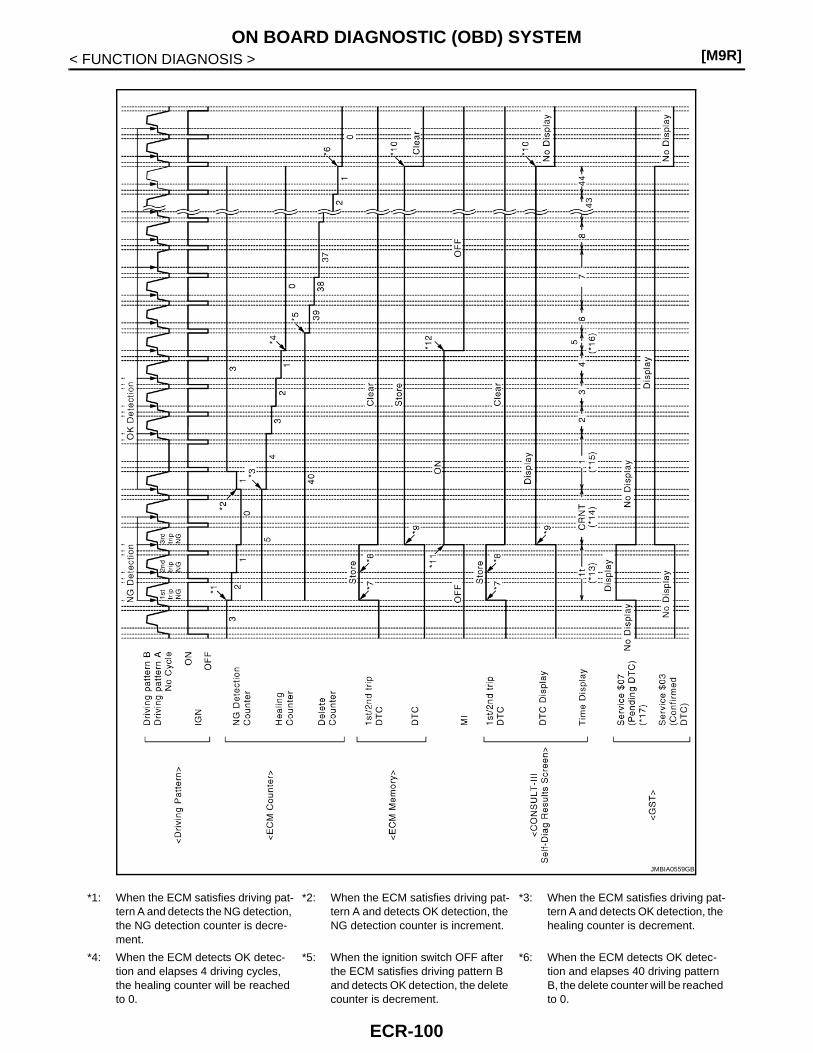
[M9R]ON BOARD DIAGNOSTIC (OBD) SYSTEM
< FUNCTION DIAGNOSIS >
*1: When the ECM satisfies driving pat-tern A and detects the NG detection, the NG detection counter is decre-ment.
*2: When the ECM satisfies driving pat-tern A and detects OK detection, the NG detection counter is increment.
*3: When the ECM satisfies driving pat-tern A and detects OK detection, the healing counter is decrement.
*4: When the ECM detects OK detec-tion and elapses 4 driving cycles, the healing counter will be reached to 0.
*5: When the ignition switch OFF after the ECM satisfies driving pattern B and detects OK detection, the delete counter is decrement.
*6: When the ECM detects OK detec-tion and elapses 40 driving pattern B, the delete counter will be reached to 0.
JMBIA0559GB
ECR-100

ON BOARD DIAGNOSTIC (OBD) SYSTEM[M9R]
C
D
E
F
G
H
I
J
K
L
M
A
CR
N
P
O
< FUNCTION DIAGNOSIS >
E
<Driving Pattern A>Driving pattern A means the vehicle operation as follows:Engine speed should go over 500 rpm at least 5 seconds and the DTC Confirmation Procedure is performed.• The healing counter will be set when the malfunction is detected.• The healing counter will be decrement when the same malfunction is not detected.• The MI will go off when the healing counter reaches 0.<Driving Pattern B>Driving pattern B means the vehicle operation as follows:Driving pattern A and (1)-(3) are satisfied.
• The delete counter will be cleared when the malfunction is detected.• The delete counter will be decrement when the same malfunction is not detected.• The DTC will not be displayed after the delete counter reaches 0.
CONSULT-III Function INFOID:0000000001581433
FUNCTION
*: The following emission-related diagnostic information is cleared when the ECM memory is erased.
• Diagnostic trouble codes
• 1st trip diagnostic trouble codes
• 2nd trip diagnostic trouble codes
ENGINE CONTROL COMPONENT PARTS/CONTROL SYSTEMS APPLICATION
*7: When the malfunction is detected for the first time, 1st trip DTC is stored in the ECM memory.
*8: When the sam malfunction is detect-ed during 2nd consecutive trip, 2nd trip DTC is stored and 1st trip DTC is cleared.
*9: When the ECM detects NG detec-tion, DTC is stored.
*10: When the detect counter is reached to 0, DTC is cleared.
*11: When the same malfunction is de-tected in 3 consecutive trips, MI will light up.
*12: MI will go off after vehicle is driven 5 times (driving pattern A) without any malfunctions.
*13: When the ECM detects 1st/2nd trip NG detection, the time “1t” will be displayed in the CONSULT-III Self diagnostic screen.
*14: When the ECM detects 3rd trip NG detection, the time “CRNT” will be displayed in the CONSULT-III Self diagnostic screen.
*15: When the healing counter is 4, the time “1” will be displayed in the CONSULT-III Self diagnostic screen.
*16: When the healing counter is 0 and the delete counter is 40, the time “5” will be displayed in the CONSULT-III Self diagnostic screen.
*17: The 1st/2nd trip DTC (pending DTC) is displayed in Service $07 of GST.
PBIB2049E
Diagnostic test mode Function
Work supportThis mode enables a technician to adjust some devices faster and more accurately by following the indications on the CONSULT-III unit.
Self-diagnostic results Self-diagnostic results such as DTC can be read and erased quickly.*
Data monitor Input/Output data in the ECM can be read.
Active testDiagnostic Test Mode in which CONSULT-III drives some actuators apart from the ECMs and also shifts some parameters in a specified range.
ECM part number ECM part number and homologation number can be read.
ECR-101

[M9R]ON BOARD DIAGNOSTIC (OBD) SYSTEM
< FUNCTION DIAGNOSIS >
X: Applicable
WORK SUPPORT MODE
Work Item
Item
DIAGNOSTIC TEST MODE
WORK SUPPORT
SELF-DIAG RESULTS
(DTC)
DATA MON-ITOR
ACTIVE TEST
EN
GIN
E C
ON
TR
OL
CO
MP
ON
EN
T P
AR
TS INPUT
Crankshaft position sensor × ×
Camshaft position sensor × ×
Engine coolant temperature sensor × ×
Vehicle speed signal ×
Accelerator pedal position sensor 1 × ×
Accelerator pedal position sensor 2 × ×
Throttle position sensor × ×
Fuel rail pressure sensor × ×
Mass air flow sensor × ×
Intake air temperature sensor × ×
Fuel temperature sensor × ×
Turbocharger boost sensor × ×
Battery voltage × ×
Stop lamp switch × ×
Clutch pedal position switch × ×
ASCD steering switch ×
EGR volume control valve control position sensor × ×
Refrigerant pressure sensor × ×
Barometric pressure sensor (built-into ECM) × ×
A/F ratio sensor 1 × ×
Exhaust gas pressure sensor × ×
Exhaust gas temperature sensor 1 ×
Exhaust gas temperature sensor 2 × ×
Exhaust gas temperature sensor 3 × ×
Differential exhaust pressure sensor × ×
OUTPUT
Fuel pump × × ×
Fuel injector × × ×
Fuel rail pressure control valve × × ×
Glow control unit × × ×
Turbocharger boost control solenoid valve × × ×
Turbocharger cooling pump × × ×
EGR volume control valve × × ×
EGR cooler bypass valve control solenoid valve × × ×
Throttle control motor × ×
Cooling fan motor × × ×
ECR-102

ON BOARD DIAGNOSTIC (OBD) SYSTEM[M9R]
C
D
E
F
G
H
I
J
K
L
M
A
CR
N
P
O
< FUNCTION DIAGNOSIS >
E
SELF-DIAGNOSTIC MODE
Self Diagnostic ItemRegarding items detected in “SELF-DIAG RESULTS” mode, refer to — ECR-315, "DTC Index".
DATA MONITOR MODE
WORK ITEM DESCRIPTION USAGE
CONFIG INITIALIZE • In this mode vehicle configuration is initialized. When ECM is replaced
INJ ADJ VAL REGIST • In this mode, fuel injector adjustment value is registered.When ECM or fuel injector(s) is re-placed
CYL OPERATION DIAG • In this mode, the diagnosis of each cylinder is performed. To detect malfunctioning cylinder
HI PRESS CIRC DIAG• In this mode, the diagnosis of high pressure fuel circuit is per-
formed.To detect malfunctioning portion of high pressure fuel circuit
EGR/V LEARN CLR• In this mode, EGR volume control valve closed position learning is
cleared.When EGR volume control valve is removed or replaced
TP POS LEARN CLR • In this mode, throttle valve closed position learning is cleared.When electric throttle control actu-ator is removed or replaced
DPF DATA CLEAR • In this mode, estimated PM amount in DPF is cleared. When DPF is replaced
ZFC VALUE RESET• In this mode, ZFC (Zero Fuel Calibration) and NVC (Nominal Volt-
age Calibration) are reset.
When ECM or fuel injector(s) is re-placedWhen ECM is reprogrammed
A/F LARN CLR • In this mode, A/F sensor learning value is cleared.
When A/F sensor 1 is replacedWhen ECM is replaced with used one which stores the A/F sensor learning value of another A/F sen-sor 1
COMPRESSION TEST
• This mode is used to:Find out the general condition of the combustion chamber (auto-matic mode).Take cylinder compression measurement without disconnecting fuel injector harness connector or crankshaft position sensor (man-ual mode).
SERVC REGENERATION • In this mode, service regeneration is performed.
When DPF is replaced with new oneCAUTION:Never perform when DPF is not replaced with new one. PDF may be damaged because re-generation is not performed at appropriate timing.
MONITOR ITEM UNIT CONDITION SPECIFICATION
IGN SW ABSENT/PRESENT• Ignition switch condition is displayed.
ABSENT: Ignition switch OFFPRESENT: Ignition switch ON
NATS INACT/ACTIV• NATS condition is displayed.
INACT: InactiveACTIV: Active
GLOW CONT INACT/ACTIV• Glow control condition is displayed.
INACT: Glow is OFF.ACTIV: Glow is ON.
A/C RELAY NODON/DONE• A/C relay condition is displayed.
NODON: A/C relay is OFF.DONE: A/C relay is ON.
CLUTCH STATUS NO/YES• Clutch condition is displayed
NO: Clutch pedal is released.YES: Clutch pedal is depressed.
ECR-103

[M9R]ON BOARD DIAGNOSTIC (OBD) SYSTEM
< FUNCTION DIAGNOSIS >
ENGINE STATUS '+APC/RUN/OFF
• Engine status is displayed.'+APC: Ignition switch ONRUN: Engine is running.OFF: During self shut-off
BPP SW RELSD/PRSSD• Brake pedal condition is displayed.
RELSD: Brake pedal is released.PRSSD: Brake pedal is depressed.
ENGINE START PRHBT/ATHRD• Engine stating authority is displayed.
PRHBT: ProhibitedATHRD: Authorized
IMPACT DETECTED NO/YES• Impact detection is displayed.
NO: Impact is not detected.YES Impact is detected.
A/C APPLD NO/YES• A/C application is displayed.
NO: A/C is not applied.YES: A/C is applied.
GLOW CONT SIGNAL ABSENT/PRESENT• Glow control signal is displayed.
ABSENT: Glow control is OFF.PRESENT: Glow control is ON.
COOLING FAN LOW INACT/ACTIV• Cooling fan low speed control is displayed.
INACT: Low circuit is OFF.ACTIV: Low circuit is ON.
COOLING FAN HIGH INACT/ACTIV• Cooling fan high speed control is displayed.
INACT: High circuit is OFF.ACTIV: High circuit is ON.
CKP CMP SYNCHRO NODON/DONE
• Crankshaft position sensor and camshaft position sen-sor synchronization is displayed.NODON: Not synchronizedDONE: Synchronized
ECM-TCM COMM ABSENT/PRESENT• ECM-TCM communication condition is displayed.
ABSENT: Not communicatedPRESENT: Communicated
A/C COMP INACT/ACTIV• A/C compressor status is displayed.
INACT: A/C compressor is OFF.ACTIV: A/C compressor is ON.
NATS CODE RGST NO/YES• NATS code registration condition is displayed.
NO: Not registered.YES Registered.
CPP SW INACT/ACTIV• Clutch pedal condition is displayed.
INACT: Clutch pedal is released.ACTIV: Clutch pedal is depressed.
EGR BYPAS S/V INACT/ACTIV
• EGR cooler bypass valve control solenoid valve condi-tion is displayed.INACT: EGR cooler bypass valve control solenoid valve is not operated.ACTIV: EGR cooler bypass valve control solenoid valve is operated.
TURBO COOL PUMP INACT/ACTIV• Turbocharger cooling pump condition is displayed.
INACT: Turbocharger cooling pump is not operated.ACTIV: Turbocharger cooling pump is operated.
MONITOR ITEM UNIT CONDITION SPECIFICATION
ECR-104

ON BOARD DIAGNOSTIC (OBD) SYSTEM[M9R]
C
D
E
F
G
H
I
J
K
L
M
A
CR
N
P
O
< FUNCTION DIAGNOSIS >
EA/T GEAR POS STAT1/1/2/3/4/5/6/BACK
• A/T gear position is displayed.STAT1: Neutral1: 1st gear2: 2nd gear3: 3rd gear4: 4th gear5: 5th gear6: 6th gearBack: Reverse gear
RGN INCMP STAT1 '+APC/RUN/OFF
• Incomplete status No. 1 of DPF regeneration is dis-played.'+APC: Ignition switch ONRUN: Engine is running.OFF: During self shut-off
RGN INCMP STAT2 '+APC/RUN/OFF
• Incomplete status No. 2 of DPF regeneration is dis-played.'+APC: Ignition switch ONRUN: Engine is running.OFF: During self shut-off
RGN INCMP STAT3 '+APC/RUN/OFF
• Incomplete status No. 3 of DPF regeneration is dis-played.'+APC: Ignition switch ONRUN: Engine is running.OFF: During self shut-off
RGN INCMP STAT4 '+APC/RUN/OFF
• Incomplete status No. 4 of DPF regeneration is dis-played.'+APC: Ignition switch ONRUN: Engine is running.OFF: During self shut-off
RGN INCMP STAT5 '+APC/RUN/OFF
• Incomplete status No. 5 of DPF regeneration is dis-played.'+APC: Ignition switch ONRUN: Engine is running.OFF: During self shut-off
RGN INCMP STAT6 '+APC/RUN/OFF
• Incomplete status No. 6 of DPF regeneration is dis-played.'+APC: Ignition switch ONRUN: Engine is running.OFF: During self shut-off
RGN INCMP STAT7 '+APC/RUN/OFF
• Incomplete status No. 7 of DPF regeneration is dis-played.'+APC: Ignition switch ONRUN: Engine is running.OFF: During self shut-off
RGN INCMP STAT8 '+APC/RUN/OFF
• Incomplete status No. 8 of DPF regeneration is dis-played.'+APC: Ignition switch ONRUN: Engine is running.OFF: During self shut-off
RGN INCMP STAT9 '+APC/RUN/OFF
• Incomplete status No. 9 of DPF regeneration is dis-played.'+APC: Ignition switch ONRUN: Engine is running.OFF: During self shut-off
RGN INCMP STAT10 '+APC/RUN/OFF
• Incomplete status No. 10 of DPF regeneration is dis-played.'+APC: Ignition switch ONRUN: Engine is running.OFF: During self shut-off
MONITOR ITEM UNIT CONDITION SPECIFICATION
ECR-105

[M9R]ON BOARD DIAGNOSTIC (OBD) SYSTEM
< FUNCTION DIAGNOSIS >
RGN REQ STAT1STAT1/STAT2/STAT3/
STAT4
• Request status No. 1 of DPF regeneration is displayed.STAT1: Engine stoppedSTAT2: Engine startingSTAT3: Engine runningSTAT4: During self shut-off
RGN REQ STAT2STAT1/STAT2/STAT3/
STAT4
• Request status No. 2 of DPF regeneration is displayed.STAT1: Engine stoppedSTAT2: Engine startingSTAT3: Engine runningSTAT4: During self shut-off
RGN REQ STAT3STAT1/STAT2/STAT3/
STAT4
• Request status No. 3 of DPF regeneration is displayed.STAT1: Engine stoppedSTAT2: Engine startingSTAT3: Engine runningSTAT4: During self shut-off
RGN REQ STAT4STAT1/STAT2/STAT3/
STAT4
• Request status No. 4 of DPF regeneration is displayed.STAT1: Engine stoppedSTAT2: Engine startingSTAT3: Engine runningSTAT4: During self shut-off
RGN REQ STAT5STAT1/STAT2/STAT3/
STAT4
• Request status No. 5 of DPF regeneration is displayed.STAT1: Engine stoppedSTAT2: Engine startingSTAT3: Engine runningSTAT4: During self shut-off
RGN REQ STAT6STAT1/STAT2/STAT3/
STAT4
• Request status No. 6 of DPF regeneration is displayed.STAT1: Engine stoppedSTAT2: Engine startingSTAT3: Engine runningSTAT4: During self shut-off
RGN REQ STAT7STAT1/STAT2/STAT3/
STAT4
• Request status No. 7 of DPF regeneration is displayed.STAT1: Engine stoppedSTAT2: Engine startingSTAT3: Engine runningSTAT4: During self shut-off
RGN REQ STAT8STAT1/STAT2/STAT3/
STAT4
• Request status No. 8 of DPF regeneration is displayed.STAT1: Engine stoppedSTAT2: Engine startingSTAT3: Engine runningSTAT4: During self shut-off
RGN REQ STAT9STAT1/STAT2/STAT3/
STAT4
• Request status No. 9 of DPF regeneration is displayed.STAT1: Engine stoppedSTAT2: Engine startingSTAT3: Engine runningSTAT4: During self shut-off
RGN REQ STAT10STAT1/STAT2/STAT3/
STAT4
• Request status No. 10 of DPF regeneration is dis-played.STAT1: Engine stoppedSTAT2: Engine startingSTAT3: Engine runningSTAT4: During self shut-off
EGR COOL BYPAS/V INACT/ACTIV
• EGR cooler bypass valve control solenoid valve status is displayed.INACT: EGR cooler bypass valve control solenoid valve is not operated.ACTIV: EGR cooler bypass valve control solenoid valve is operated.
EGR/V TRG ANGLE %• EGR volume control valve target opening angle is dis-
played.
MONITOR ITEM UNIT CONDITION SPECIFICATION
ECR-106

ON BOARD DIAGNOSTIC (OBD) SYSTEM[M9R]
C
D
E
F
G
H
I
J
K
L
M
A
CR
N
P
O
< FUNCTION DIAGNOSIS >
E
TRG RAIL PRES bar • Target fuel rail pressure is displayed.
TRG BOOST PRES bar or mbar • Target turbocharger boost pressure is displayed.
INJ VOLUME mg/cp • Fuel injection volume is displayed.
ACCEL PDL POS % • Accelerator pedal position is displayed.
BARO PRES bar or mbar • Barometric pressure is displayed.
RFRG PRES mbar • Refrigerant pressure is displayed.
FUEL RAIL PRES bar • Fuel rail pressure is displayed.
TC BOOST PRES bar or mbar • Turbocharger boost pressure is displayed.
EGR VALVE POS % • EGR volume control valve control position is displayed.
ENG SPEED tr/min• Engine speed computed from crankshaft position sen-
sor is displayed.
INT AIR TEMP °C • Intake air temperature is displayed.
FUEL TEMP °C • Fuel temperature is displayed.
ENG COOLAN TEMP °C • Engine coolant temperature is displayed.
BAT VOLT V • Battery voltage is displayed.
EGR POS/S VOLT V• EGR volume control valve control position sensor sig-
nal voltage is displayed.
BARO SEN VOLT V • Barometric pressure sensor signal voltage is displayed.
FRP SEN VOLT V or mV • Fuel rail pressure sensor signal voltage is displayed.
FUEL TEMP/S VOLT V or mV • Fuel temperature sensor signal voltage is displayed.
IAT SEN VOLT V or mV• Intake air temperature sensor signal voltage is dis-
played.
ECT SEN VOLT V or mV• Engine coolant temperature sensor signal voltage is
displayed.
APP SEN1 VOLT V or mV• Accelerator pedal position sensor 1 signal voltage is
displayed.
APP SEN2 VOLT V or mV• Accelerator pedal position sensor 2 signal voltage is
displayed.
MASS AIR FLOW kg/h • Mass air flow is displayed.
TRG INJ VOLUME mg/cp • Target fuel injection volume is displayed.
TRG EGR VOLUME mg/cp • Target EGR volume is displayed.
VSP/ENG SP RATIO — or % • Vehicle speed/engine speed ratio is displayed.
TRG IDLE SPD tr/min • Target idle speed is displayed.
TC BST PR/S VOLT V or mV• Turbocharger boost pressure sensor signal voltage is
displayed.
MAF SEN VOLT V or mV • Mass air flow sensor signal voltage is displayed.
RFRG PRE/S VOLT V or mV • Refrigerant pressure sensor signal voltage is displayed.
INJ1 ADJ VALUE mg/cp • Injector No. 1 adjustment value is displayed.
INJ4 ADJ VALUE mg/cp • Injector No. 4 adjustment value is displayed.
MIL — • Malfunction indicator status is displayed.
EXH GAS TEMP3 °C • Exhaust gas temperature computed from exhaust gas temperature sensor 3 is displayed.
EXH GAS TEMP2 °C • Exhaust gas temperature computed from exhaust gas temperature sensor 2 is displayed.
INJ2 ADJ VALUE mg/cp • Injector No. 2 adjustment value is displayed.
INJ3 ADJ VALUE mg/cp • Injector No. 3 adjustment value is displayed.
DIFF EXH PRES mbar • Differential exhaust pressure is displayed.
MONITOR ITEM UNIT CONDITION SPECIFICATION
ECR-107

[M9R]ON BOARD DIAGNOSTIC (OBD) SYSTEM
< FUNCTION DIAGNOSIS >
NOTE:
Any monitored item that does not match the vehicle being diagnosed is deleted from the display automatically.
ACTIVE TEST MODE
*: Leaving cooling fan OFF with CONSULT-III while engine is running may cause the engine overheat.
Diagnosis Tool Function INFOID:0000000001581434
DESCRIPTION
ASCD SET SPEED km/h • ASCD set speed is displayed.
EXH GAS PRES mbar • Exhaust gas pressure is displayed.
EX GAS PR/S VOLT V• Exhaust gas pressure sensor signal voltage is dis-
played.
MONITOR ITEM UNIT CONDITION SPECIFICATION
TEST ITEM CONDITION JUDGEMENT CHECK ITEM (REMEDY)
TC BST CONT S/V
• Ignition switch: ON• Turn turbocharger boost control
solenoid valve ON and OFF with the CONSULT-III and listen to op-eration sound.
Turbocharger boost control sole-noid valve makes an operating sound.
• Harness and connector• Turbocharger boost control valve
FRP CONTROL VALVE
• Ignition switch: ON• Turn fuel rail pressure control
valve ON and OFF with the CON-SULT-III and listen to operation sound.
Fuel rail pressure control valve makes an operating sound.
• Harness and connector• Fuel rail pressure control valve
COOLING FAN LOW*
• Ignition switch: ON• Operate cooling fan at LOW
speed and turn OFF.
Cooling fan moves at LOW speed and stops.
• Harness and connector• Cooling fan
COOLING FAN HIGH*
• Ignition switch: ON• Operate cooling fan at HIGH
speed and turn OFF.
Cooling fan moves at HIGH speed and stops.
• Harness and connector• Cooling fan
GLOW CONTROL UNIT
• Ignition switch: ON (Engine stopped)
• Turn the glow control unit ON and OFF using CONSULT-III and check voltage between glow plug terminals and ground.
Battery voltage should exist when glow control unit is ON.
• Harness and connector• Glow control unit
EGR COOLER BY-PASS CONT S/V
• Ignition switch: ON• Turn EGR cooler bypass valve
control solenoid valve ON and OFF with the CONSULT-III and listen to operation sound.
EGR cooler bypass valve control solenoid valve makes an operat-ing sound.
• Harness and connector• EGR cooler bypass valve control
solenoid valve
THROTTLE VALVE
• Ignition switch: ON• Turn throttle control motor ON and
OFF with the CONSULT-III and confirm the operation.
Throttle valve is operated.• Harness and connector• Electric throttle control actuator
FUEL PUMP
• Ignition switch: ON• Change EGR volume control
valve opening angle using CON-SULT-III
The opening angle of EGR vol-ume control valve is changed properly.
• Harness and connector• EGR volume control valve
TURBOCHARGER COOLING PUMP
• Ignition switch: ON• Turn turbocharger cooling pump
ON and OFF with the CONSULT-III and listen to operation sound.
Turbocharger cooling pump makes an operating sound.
• Harness and connector• Turbocharger cooling pump
ECR-108

ON BOARD DIAGNOSTIC (OBD) SYSTEM[M9R]
C
D
E
F
G
H
I
J
K
L
M
A
CR
N
P
O
< FUNCTION DIAGNOSIS >
E
Generic Scan Tool (OBDII scan tool) complying with SAE J1978 has8 different functions explained below.ISO9141 is used as the protocol.The name “GST” or “Generic Scan Tool” is used in this service man-ual.
FUNCTION
INSPECTION PROCEDURE1. Turn ignition switch OFF.2. Connect “GST” to data link connector, which is located under LH dash panel near the hood opener han-
dle.3. Turn ignition switch ON.4. Enter the program according to instruction on the screen or in
the operation manual.(*: Regarding GST screens in this section, sample screens areshown.)
SEF139P
Diagnostic Service Function
Service $01 READINESS TESTSThis diagnostic service gains access to current emission-related data values, including an-alog inputs and outputs, digital inputs and outputs, and system status information.
Service $03 DTCsThis diagnostic service gains access to emission-related power train trouble codes which were stored by ECM.
Service $04 CLEAR DIAG INFO
This diagnostic service can clear all emission-related diagnostic information. This in-cludes:• Clear number of diagnostic trouble codes (Service $01)• Clear diagnostic trouble codes (Service $03)• Clear trouble code for freeze frame data (Service $01)• Reset status of system monitoring test (Service $01)• Clear on board monitoring test results (Service $07)
Service $06 (ON BOARD TESTS)This diagnostic service accesses the results of on board diagnostic monitoring tests of specific components/systems that are not continuously monitored.
Service $07 (ON BOARD TESTS)This diagnostic service enables the off board test drive to obtain test results for emission-related powertrain components/systems that are continuously monitored during normal driving conditions.
Service $09 (CALIBRATION ID)This diagnostic service enables the off-board test device to request specific vehicle infor-mation such as Vehicle Identification Number (VIN) and Calibration IDs.
SEF398S
ECR-109

[M9R]ON BOARD DIAGNOSTIC (OBD) SYSTEM
< FUNCTION DIAGNOSIS >5. Perform each diagnostic mode according to each service proce-
dure.For further information, see the GST Operation Manual ofthe tool maker.
SEF416S
ECR-110
POWER SUPPLY AND GROUND CIRCUIT[M9R]
C
D
E
F
G
H
I
J
K
L
M
A
CR
N
P
O
< COMPONENT DIAGNOSIS >
E
COMPONENT DIAGNOSISPOWER SUPPLY AND GROUND CIRCUIT
Diagnosis Procedure INFOID:0000000001581435
1.CHECK GROUND CONNECTION
1. Turn ignition switch OFF and wait at least 20 seconds.2. Check ground connection E17. Refer to Ground Inspection in GI-41, "Circuit Inspection".Is the inspection result normal?YES >> GO TO 2.NO >> Repair or replace ground connection.
2.CHECK ECM GROUND CIRCUIT FOR OPEN AND SHORT
1. Disconnect ECM harness connectors.2. Check the continuity between ECM harness connector and ground.
3. Also check harness for short to power.Is the inspection result normal?YES >> GO TO 3.NO >> Repair open circuit or short to power in harness or connectors.
3.CHECK ECM POWER SUPPLY CIRCUIT-I
1. Reconnect ECM harness connectors.2. Turn ignition switch ON.3. Check the voltage between ECM harness connector terminals as follows.
Is the inspection result normal?YES >> GO TO 5.NO >> GO TO 4.
4.DETECT MALFUNCTIONING PART
Check the following.• Harness connectors M77, E105• 10A fuse (No. 4)• Harness for open or short between ECM and fuse
>> Repair open circuit or short to ground or short to power in harness or connectors.
5.CHECK ECM POWER SUPPLY CIRCUIT-II
1. Turn ignition switch OFF and wait at least 20 seconds.2. Check the voltage between ECM harness connector terminals as follows.
ECMGround Continuity
Connector Terminal
E121
123
Ground Existed124
125
128
(+) (−)Voltage
Connector Terminal Connector Terminal
E121 109 E121 128 Battery voltage
ECR-111

[M9R]POWER SUPPLY AND GROUND CIRCUIT
< COMPONENT DIAGNOSIS >
Is the inspection result normal?YES >> GO TO 12.NO-1 >> Battery voltage does not exist: GO TO 6.NO-2 >> Battery voltage exists for more than 20 seconds: GO TO 9.
6.CHECK ECM POWER SUPPLY CIRCUIT-III
1. Turn ignition switch OFF and wait at least 20 seconds.2. Check the voltage between ECM harness connector terminals as follows.
Is the inspection result normal?YES >> GO TO 7.NO >> GO TO 9.
7.CHECK ECM POWER SUPPLY CIRCUIT-IV
1. Disconnect ECM harness connector.2. Disconnect IPDM E/R harness connector E11.3. Check the continuity between ECM harness connector and IPDM E/R harness connector.
4. Also check harness for short to ground and short to power.Is the inspection result normal?YES >> GO TO 12.NO >> GO TO 8.
8.DETECT MALFUNCTIONING PART
Check the following.• Harness or connectors E7, F121• Harness for open or short between ECM and IPDM E/R
>> Repair open circuit or short to ground or short to power in harness or connectors.
9.CHECK ECM POWER SUPPLY CIRCUIT-V
1. Disconnect ECM harness connector.2. Disconnect IPDM E/R harness connector E11.3. Check the continuity between ECM harness connector and IPDM E/R harness connector.
4. Also check harness for short to ground and short to power.Is the inspection result normal?
(+) (−)Voltage
Connector Terminal Connector Terminal
F13293
E121 128After turning ignition switch OFF, battery voltage will ex-ist for 20 seconds, then drop approximately 0V.94
(+) (−)Voltage
Connector Terminal Connector Terminal
F132 62 E121 128 Battery voltage
ECM IPDM E/RContinuity
Connector Terminal Connector Terminal
E13293
E11 9 Existed94
ECM IPDM E/RContinuity
Connector Terminal Connector Terminal
F132 62 E11 15 Existed
ECR-112

POWER SUPPLY AND GROUND CIRCUIT[M9R]
C
D
E
F
G
H
I
J
K
L
M
A
CR
N
P
O
< COMPONENT DIAGNOSIS >
E
YES >> GO TO 11.NO >> GO TO 10.
10.DETECT MALFUNCTIONING PART
Check the following.• Harness or connectors E7, F121• Harness for open or short between ECM and IPDM E/R
>> Repair open circuit or short to ground or short to power in harness or connectors.
11.CHECK 20A FUSE
1. Disconnect 20A fuse (No. 52) from IPDM E/R.2. Check 20A fuse.Is the inspection result normal?YES >> GO TO 12.NO >> Replace 20A fuse.
12.CHECK INTERMITTENT INCIDENT
Refer to GI-39, "Intermittent Incident".Is the inspection result normal?YES >> Replace IPDM E/R.NO >> Repair open circuit or short to power in harness or connectors.
ECR-113
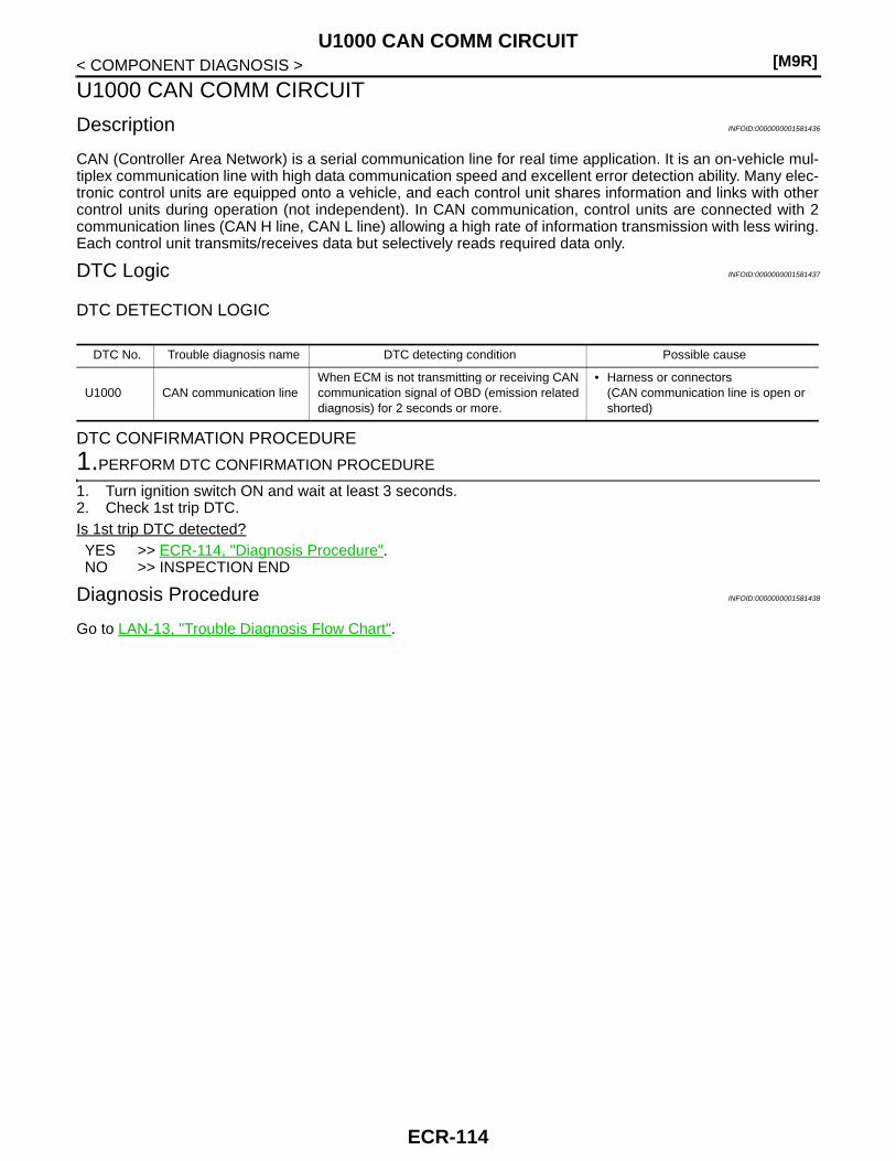
[M9R]U1000 CAN COMM CIRCUIT
< COMPONENT DIAGNOSIS >
U1000 CAN COMM CIRCUIT
Description INFOID:0000000001581436
CAN (Controller Area Network) is a serial communication line for real time application. It is an on-vehicle mul-tiplex communication line with high data communication speed and excellent error detection ability. Many elec-tronic control units are equipped onto a vehicle, and each control unit shares information and links with othercontrol units during operation (not independent). In CAN communication, control units are connected with 2communication lines (CAN H line, CAN L line) allowing a high rate of information transmission with less wiring.Each control unit transmits/receives data but selectively reads required data only.
DTC Logic INFOID:0000000001581437
DTC DETECTION LOGIC
DTC CONFIRMATION PROCEDURE
1.PERFORM DTC CONFIRMATION PROCEDURE
1. Turn ignition switch ON and wait at least 3 seconds.2. Check 1st trip DTC.Is 1st trip DTC detected?YES >> ECR-114, "Diagnosis Procedure".NO >> INSPECTION END
Diagnosis Procedure INFOID:0000000001581438
Go to LAN-13, "Trouble Diagnosis Flow Chart".
DTC No. Trouble diagnosis name DTC detecting condition Possible cause
U1000 CAN communication lineWhen ECM is not transmitting or receiving CAN communication signal of OBD (emission related diagnosis) for 2 seconds or more.
• Harness or connectors(CAN communication line is open or shorted)
ECR-114
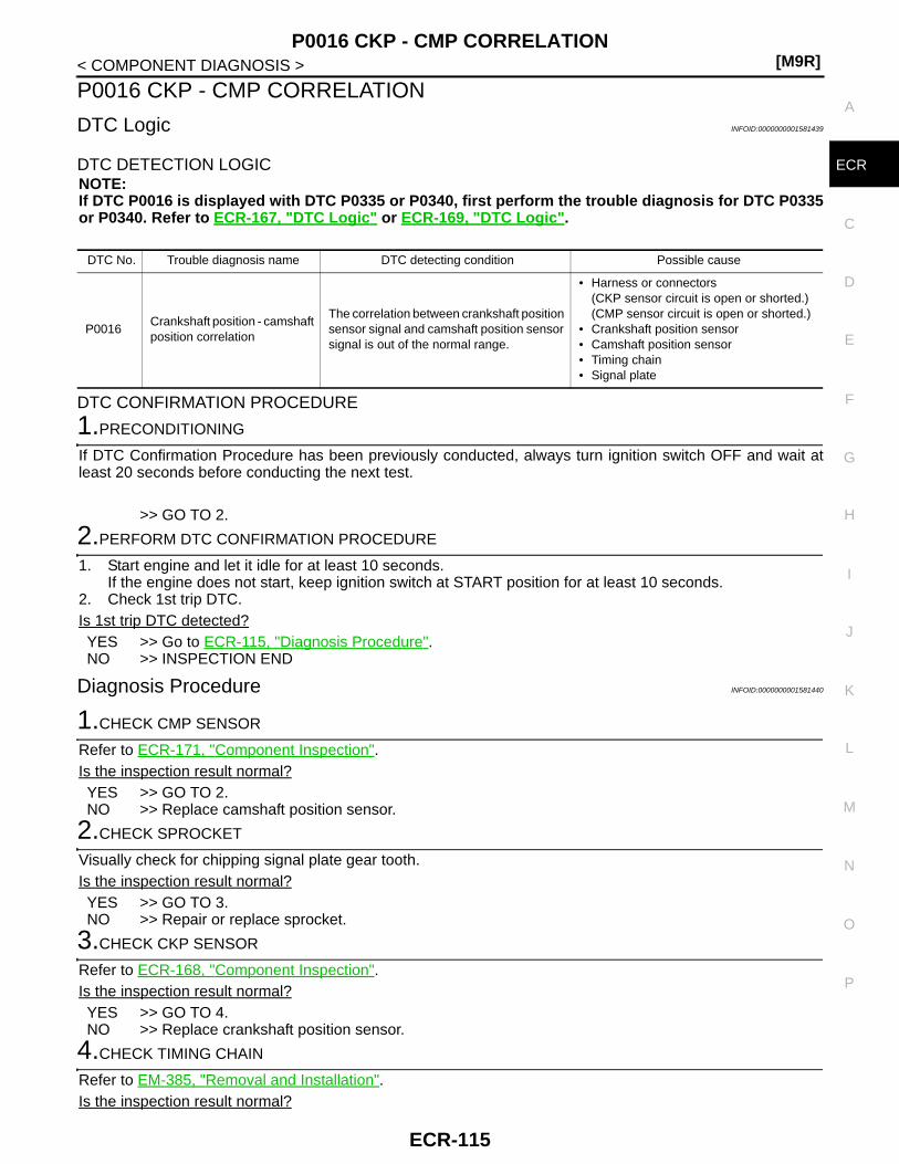
P0016 CKP - CMP CORRELATION[M9R]
C
D
E
F
G
H
I
J
K
L
M
A
CR
N
P
O
< COMPONENT DIAGNOSIS >
E
P0016 CKP - CMP CORRELATION
DTC Logic INFOID:0000000001581439
DTC DETECTION LOGICNOTE:If DTC P0016 is displayed with DTC P0335 or P0340, first perform the trouble diagnosis for DTC P0335or P0340. Refer to ECR-167, "DTC Logic" or ECR-169, "DTC Logic".
DTC CONFIRMATION PROCEDURE
1.PRECONDITIONING
If DTC Confirmation Procedure has been previously conducted, always turn ignition switch OFF and wait atleast 20 seconds before conducting the next test.
>> GO TO 2.
2.PERFORM DTC CONFIRMATION PROCEDURE
1. Start engine and let it idle for at least 10 seconds.If the engine does not start, keep ignition switch at START position for at least 10 seconds.
2. Check 1st trip DTC.Is 1st trip DTC detected?YES >> Go to ECR-115, "Diagnosis Procedure".NO >> INSPECTION END
Diagnosis Procedure INFOID:0000000001581440
1.CHECK CMP SENSOR
Refer to ECR-171, "Component Inspection".Is the inspection result normal?YES >> GO TO 2.NO >> Replace camshaft position sensor.
2.CHECK SPROCKET
Visually check for chipping signal plate gear tooth.Is the inspection result normal?YES >> GO TO 3.NO >> Repair or replace sprocket.
3.CHECK CKP SENSOR
Refer to ECR-168, "Component Inspection".Is the inspection result normal?YES >> GO TO 4.NO >> Replace crankshaft position sensor.
4.CHECK TIMING CHAIN
Refer to EM-385, "Removal and Installation".Is the inspection result normal?
DTC No. Trouble diagnosis name DTC detecting condition Possible cause
P0016Crankshaft position - camshaft position correlation
The correlation between crankshaft position sensor signal and camshaft position sensor signal is out of the normal range.
• Harness or connectors(CKP sensor circuit is open or shorted.)(CMP sensor circuit is open or shorted.)
• Crankshaft position sensor• Camshaft position sensor• Timing chain• Signal plate
ECR-115
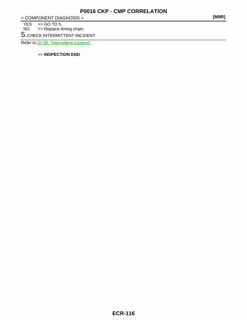
[M9R]P0016 CKP - CMP CORRELATION
< COMPONENT DIAGNOSIS >YES >> GO TO 5.NO >> Replace timing chain.
5.CHECK INTERMITTENT INCIDENT
Refer to GI-39, "Intermittent Incident".
>> INSPECTION END
ECR-116
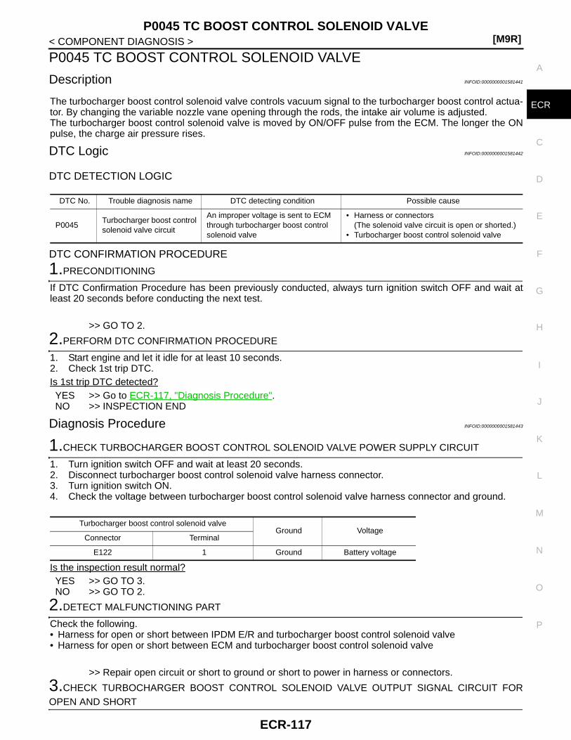
P0045 TC BOOST CONTROL SOLENOID VALVE[M9R]
C
D
E
F
G
H
I
J
K
L
M
A
CR
N
P
O
< COMPONENT DIAGNOSIS >
E
P0045 TC BOOST CONTROL SOLENOID VALVE
Description INFOID:0000000001581441
The turbocharger boost control solenoid valve controls vacuum signal to the turbocharger boost control actua-tor. By changing the variable nozzle vane opening through the rods, the intake air volume is adjusted.The turbocharger boost control solenoid valve is moved by ON/OFF pulse from the ECM. The longer the ONpulse, the charge air pressure rises.
DTC Logic INFOID:0000000001581442
DTC DETECTION LOGIC
DTC CONFIRMATION PROCEDURE
1.PRECONDITIONING
If DTC Confirmation Procedure has been previously conducted, always turn ignition switch OFF and wait atleast 20 seconds before conducting the next test.
>> GO TO 2.
2.PERFORM DTC CONFIRMATION PROCEDURE
1. Start engine and let it idle for at least 10 seconds.2. Check 1st trip DTC.Is 1st trip DTC detected?YES >> Go to ECR-117, "Diagnosis Procedure".NO >> INSPECTION END
Diagnosis Procedure INFOID:0000000001581443
1.CHECK TURBOCHARGER BOOST CONTROL SOLENOID VALVE POWER SUPPLY CIRCUIT
1. Turn ignition switch OFF and wait at least 20 seconds.2. Disconnect turbocharger boost control solenoid valve harness connector.3. Turn ignition switch ON.4. Check the voltage between turbocharger boost control solenoid valve harness connector and ground.
Is the inspection result normal?YES >> GO TO 3.NO >> GO TO 2.
2.DETECT MALFUNCTIONING PART
Check the following.• Harness for open or short between IPDM E/R and turbocharger boost control solenoid valve• Harness for open or short between ECM and turbocharger boost control solenoid valve
>> Repair open circuit or short to ground or short to power in harness or connectors.
3.CHECK TURBOCHARGER BOOST CONTROL SOLENOID VALVE OUTPUT SIGNAL CIRCUIT FOROPEN AND SHORT
DTC No. Trouble diagnosis name DTC detecting condition Possible cause
P0045Turbocharger boost control solenoid valve circuit
An improper voltage is sent to ECM through turbocharger boost control solenoid valve
• Harness or connectors(The solenoid valve circuit is open or shorted.)
• Turbocharger boost control solenoid valve
Turbocharger boost control solenoid valveGround Voltage
Connector Terminal
E122 1 Ground Battery voltage
ECR-117

[M9R]P0045 TC BOOST CONTROL SOLENOID VALVE
< COMPONENT DIAGNOSIS >1. Turn ignition switch OFF and wait at least 20 seconds.2. Disconnect ECM harness connector.3. Check the continuity between turbocharger boost control solenoid valve harness connector and ECM har-
ness connector.
4. Also check harness for short to ground and short to power. Is the inspection result normal?YES >> GO TO 5.NO >> GO TO 4.
4.DETECT MALFUNCTIONING PART
Check the following.• Harness connector E7, F121• Harness for open or short between ECM and turbocharger boost control solenoid valve
>> Repair open circuit or short to ground or short to power in harness or connectors.
5.CHECK TURBOCHARGER BOOST CONTROL SOLENOID VALVE
Refer to ECR-118, "Component Inspection".Is the inspection result normal?YES >> GO TO 6.NO >> Replace turbocharger boost control solenoid valve.
6.CHECK INTERMITTENT INCIDENT
Refer to GI-39, "Intermittent Incident".
>> INSPECTION END
Component Inspection INFOID:0000000001581444
1.CHECK TURBOCHARGER BOOST CONTROL SOLENOID VALVE
1. Turn ignition switch OFF.2. Disconnect turbocharger boost control solenoid valve harness connector.3. Check the resistance between turbocharger boost control solenoid valve terminals as follows.
Is the inspection result normal?YES >> INSPECTION ENDNO >> Replace turbocharger boost control solenoid valve.
Turbocharger boost control solenoid valve ECMContinuity
Connector Terminal Connector Terminal
E122 2 F132 57 Existed
Terminals Resistance
1 and 2 0.006 - 1 kΩ
ECR-118

P0089 FUEL PUMP[M9R]
C
D
E
F
G
H
I
J
K
L
M
A
CR
N
P
O
< COMPONENT DIAGNOSIS >
E
P0089 FUEL PUMP
DTC Logic INFOID:0000000001581445
DTC DETECTION LOGIC
DTC CONFIRMATION PROCEDURE
1.PRECONDITIONING
If DTC Confirmation Procedure has been previously conducted, always turn ignition switch OFF and wait atleast 20 seconds before conducting the next test.
>> GO TO 2.
2.PERFORM DTC CONFIRMATION PROCEDURE
1. Start engine and let it idle for at least 10 seconds.2. Check 1st trip DTC.Is 1st trip DTC detected?YES >> Go to ECR-119, "Diagnosis Procedure".NO >> INSPECTION END
Diagnosis Procedure INFOID:0000000001581446
1.PERFORM FUEL FILTER AIR BLEEDING
NOTE:If the DTC is detected because of air mixed with fuel (i.e.: caused by lack of fuel), it may become normal byperforming following procedure. 1. Turn ignition switch ON.2. Perform Fuel Filter Air Bleeding. Refer to FL-33, "Air Bleeding".3. Erase DTC.4. Perform DTC confirmation procedure again, refer to ECR-119, "DTC Logic".Is 1st trip DTC detected?Yes >> GO TO 2.No >> INSPECTION END
2.CHECK FUEL RAIL PRESSURE SENSOR
Refer to ECR-151, "Component Inspection".OK or NGOK >> GO TO 3.NG >> Replace fuel rail.
3.CHECK FUEL INJECTOR
Perform ECR-156, "Component Inspection".OK or NGOK >> GO TO 5.NG >> GO TO 4.
4.REPLACE FUEL INJECTOR
DTC No. Trouble diagnosis name DTC detecting condition Possible cause
P0089 Fuel pump performance Fuel pressure is out of the target range
• Harness or connectors(Fuel pump circuit is open or shorted.)
• Fuel pump• Fuel injector• Fuel filter• Air mixed with fuel• Lack of fuel• Fuel rail pressure sensor
ECR-119
[M9R]P0089 FUEL PUMP
< COMPONENT DIAGNOSIS >1. Replace fuel injector of malfunctioning cylinder.2. Perform Injector adjustment value registration. Refer to ECR-14, "INJECTOR ADJUSTMENT VALUE
REGISTRATION : Special Repair Requirement".
>> INSPECTION END
5.CHECK FUEL PUMP
Perform ECR-120, "Component Inspection".OK or NGOK >> GO TO 6.NG >> Replace Fuel pump.
6.CHECK INTERMITTENT INCIDENT
Refer to GI-39, "Intermittent Incident".
>> INSPECTION END
Component Inspection INFOID:0000000001581447
1.CHECK FUEL PUMP
1. Turn ignition switch OFF.2. Disconnect fuel pump harness connector.3. Check the resistance between fuel pump terminals as follows.
Is the inspection result normal?YES >> INSPECTION ENDNO >> Replace fuel pump.
Terminals Resistance
1 and 2 2 - 6 Ω
ECR-120

P0090 FUEL PUMP[M9R]
C
D
E
F
G
H
I
J
K
L
M
A
CR
N
P
O
< COMPONENT DIAGNOSIS >
E
P0090 FUEL PUMP
DTC Logic INFOID:0000000001581448
DTC DETECTION LOGIC
DTC CONFIRMATION PROCEDURE
1.PRECONDITIONING
If DTC Confirmation Procedure has been previously conducted, always turn ignition switch OFF and wait atleast 20 seconds before conducting the next test.
>> GO TO 2.
2.PERFORM DTC CONFIRMATION PROCEDURE
1. Turn ignition switch ON and wait at least 10 seconds.2. Check 1st trip DTC.Is 1st trip DTC detected?YES >> Go to ECR-121, "Diagnosis Procedure".NO >> INSPECTION END
Diagnosis Procedure INFOID:0000000001581449
1.CHECK FUEL PUMP POWER SUPPLY CIRCUIT
1. Turn ignition switch OFF and wait at least 20 seconds.2. Disconnect fuel pump harness connector.3. Turn ignition switch ON.4. Check the voltage between fuel pump harness connector and ground.
Is the inspection result normal?YES >> GO TO 3.NO >> GO TO 2.
2.DETECT MALFUNCTIONING PART
Check the following.• Harness connector E7, F121• Harness for open or short between IPDM E/R and fuel pump• Harness for open or short between ECM and fuel pump
>> Repair open circuit or short to ground or short to power in harness or connectors.
3.CHECK FUEL PUMP OUTPUT SIGNAL CIRCUIT FOR OPEN AND SHORT
1. Turn ignition switch OFF and wait at least 20 seconds.2. Disconnect ECM harness connector.3. Check the continuity between fuel pump harness connector and ECM harness connector.
DTC No. Trouble diagnosis name DTC detecting condition Possible cause
P0090 Fuel pump circuit
ECM detects fuel pump circuit is open.
• Harness or connectors(The fuel pump circuit is open or shorted.)
• Fuel pump
ECM detects fuel pump circuit is short to ground.
ECM detects fuel pump circuit is short to power.
Fuel pumpGround Voltage
Connector Terminal
F143 1 Ground Battery voltage
ECR-121
[M9R]P0090 FUEL PUMP
< COMPONENT DIAGNOSIS >
4. Also check harness for short to ground and short to power. Is the inspection result normal?YES >> GO TO 4.NO >> Repair open circuit or short to ground or short to power in harness or connectors.
4.CHECK FUEL PUMP
Refer to ECR-122, "Component Inspection".Is the inspection result normal?Yes >> GO TO 5.No >> Replace fuel pump.
5.CHECK INTERMITTENT INCIDENT
Refer to GI-39, "Intermittent Incident".
>> INSPECTION END
Component Inspection INFOID:0000000001581450
1.CHECK FUEL PUMP
1. Turn ignition switch OFF.2. Disconnect fuel pump harness connector.3. Check the resistance between fuel pump terminals as follows.
Is the inspection result normal?YES >> INSPECTION ENDNO >> Replace fuel pump.
Fuel pump ECMContinuity
Connector Terminal Connector Terminal
F143 2 F132 89 Existed
Terminals Resistance
1 and 2 1.5 - 1,000 Ω
ECR-122

P0100 MAF SENSOR[M9R]
C
D
E
F
G
H
I
J
K
L
M
A
CR
N
P
O
< COMPONENT DIAGNOSIS >
E
P0100 MAF SENSOR
Description INFOID:0000000001581451
The mass air flow sensor is place in the stream of intake air. It measures the intake flow rate by measuring apart of the entire intake flow. The mass air flow sensor controls the temperature of the hot wire to a certainamount. The heat generated by the hot wire is reduced as the intake air flows around it. The more air, thegreater the heat loss.Therefore, the electirc current supplied to hot wire is changed to maintain the temperature of the hot wire as airflow increases. The ECM detects the air flow by means of this current change.
DTC Logic INFOID:0000000001581452
DTC DETECTION LOGIC
DTC CONFIRMATION PROCEDURE
1.PRECONDITIONING
If DTC Confirmation Procedure has been previously conducted, always turn ignition switch OFF and wait atleast 20 seconds before conducting the next test.
>> GO TO 2.
2.PERFORM DTC CONFIRMATION PROCEDURE-I
1. Turn ignition switch ON and wait at least 10 seconds.2. Check 1st trip DTC.Is 1st trip DTC detected?YES >> Go to ECR-123, "Diagnosis Procedure".NO >> GO TO 3.
3.PERFORM DTC CONFIRMATION PROCEDURE-II
1. Turn ignition switch OFF and wait at least 20 seconds.2. Turn ignition switch ON and wait at least 10 seconds.3. Check 1st trip DTC.Is 1st trip DTC detected?YES >> Go to ECR-123, "Diagnosis Procedure".NO >> INSPECTION END
Diagnosis Procedure INFOID:0000000001581453
1.CHECK GROUND CONNECTIONS
1. Turn ignition switch OFF and wait at least 20 seconds.2. Check ground connection E17. Refer to Ground inspection in GI-41, "Circuit Inspection".Is the inspection result normal?YES >> GO TO 2.NO >> Repair or replace ground connection.
2.CHECK MASS AIR FLOW SENSOR POWER SUPPLY CIRCUIT
1. Disconnect mass air flow sensor harness connector.2. Turn ignition switch ON.
DTC No. Trouble diagnosis name DTC detecting condition Possible cause
P0100
Mass air flow sensor circuit low input
An excessively low voltage from the sensor is sent to ECM.
• Harness or connectors(Mass air flow sensor circuit is open or shorted.)
• Mass air flow sensor
Mass air flow sensor circuit high input
An excessively high voltage from the sensor is sent to ECM.
Mass air flow sensor circuit range/performance
An improper voltage from the sensor is sent to ECM during self shut-off.
ECR-123

[M9R]P0100 MAF SENSOR
< COMPONENT DIAGNOSIS >3. Check the voltage between mass air flow sensor harness connector and ground.
Is the inspection result normal?YES >> GO TO 4.NO >> GO TO 3.
3.DETECT MALFUNCTIONING PART
Check the following.• Harness for open or short between IPDM E/R and mass air flow sensor• Harness for open or short between ECM and mass air flow sensor
>> Repair open circuit or short to ground or short to power in harness or connectors.
4.CHECK MASS AIR FLOW SENSOR GROUND CIRCUIT FOR OPEN AND SHORT
1. Turn ignition switch OFF and wait at least 20 seconds.2. Check the continuity between mass air flow sensor harness connector and ECM harness connector.
3. Also check harness for short to ground and short to power. Is the inspection result normal?YES >> GO TO 6.NO >> GO TO 5.
5.DETECT MALFUNCTIONING PART
Check the following.• Harness connector E6, F123• Harness for open or short between ECM and mass air flow sensor
>> Repair open circuit or short to ground or short to power in harness or connectors.
6.CHECK MASS AIR FLOW SENSOR INPUT SIGNAL CIRCUIT FOR OPEN AND SHORT
1. Check the continuity between mass air flow sensor harness connector and ECM harness connector.
2. Also check harness for short to ground and short to power. Is the inspection result normal?YES >> GO TO 8.NO >> GO TO 7.
7.DETECT MALFUNCTIONING PART
Check the following.• Harness connector E6, F123• Harness for open or short between ECM and mass air flow sensor
>> Repair open circuit or short to ground or short to power in harness or connectors.
8.CHECK MASS AIR FLOW SENSOR
Mass air flow sensorGround Voltage
Connector Terminal
E123 2 Ground Battery voltage
Mass air flow sensor ECMContinuity
Connector Terminal Connector Terminal
E123 3 F132 87 Existed
Mass air flow sensor ECMContinuity
Connector Terminal Connector Terminal
E123 4 F132 80 Existed
ECR-124

P0100 MAF SENSOR[M9R]
C
D
E
F
G
H
I
J
K
L
M
A
CR
N
P
O
< COMPONENT DIAGNOSIS >
E
Refer to ECR-125, "Component Inspection".Is the inspection result normal?YES >> GO TO 9.NO >> Replace mass air flow sensor.
9.CHECK INTERMITTENT INCIDENT
Refer to GI-39, "Intermittent Incident".
>> INSPECTION END
Component Inspection INFOID:0000000001581454
1.CHECK MASS AIR FLOW SENSOR
1. Turn ignition switch OFF and wait at least 20 seconds.2. Reconnect all harness connectors disconnected.3. Start engine and warm it up to normal operating temperature.4. Check the voltage between ECM harness connector terminals as follows.
*: Check for linear voltage rise in response to engine being increased to about 4,000 rpm.
Is the inspection result normal?YES >> INSPECTION ENDNO >> Replace mass air flow sensor.
(+) (−)Condition Voltage
Connector Terminal Connector Terminal
F13280
(MAF sensor signal)
F13287
(Sensor ground)
Ignition switch ON (Engine stopped.) Approx. 0.4V
Idle (Engine is warmed-up to normal operating temperature.)
1.1 - 1.4V
Idle to about 4,000 rpm 1.1 - 1.4V to Approx. 4.0V*
ECR-125

[M9R]P0101 MAF SENSOR
< COMPONENT DIAGNOSIS >
P0101 MAF SENSOR
Description INFOID:0000000001581455
The mass air flow sensor is place in the stream of intake air. It measures the intake flow rate by measuring apart of the entire intake flow. The mass air flow sensor controls the temperature of the hot wire to a certainamount. The heat generated by the hot wire is reduced as the intake air flows around it. The more air, thegreater the heat loss.Therefore, the electirc current supplied to hot wire is changed to maintain the temperature of the hot wire as airflow increases. The ECM detects the air flow by means of this current change.
DTC Logic INFOID:0000000001581456
DTC DETECTION LOGIC
DTC CONFIRMATION PROCEDURE
1.PRECONDITIONING
If DTC Confirmation Procedure has been previously conducted, always turn ignition switch OFF and wait atleast 20 seconds before conducting the next test.CAUTION:Always drive vehicle at a safe speed.
>> GO TO 2.
2.PERFORM DTC CONFIRMATION PROCEDURE-I
1. Start engine and let it idle for at least 40 seconds.2. Check 1st trip DTC.Is 1st trip DTC detected?YES >> Go to ECR-127, "Diagnosis Procedure".NO >> GO TO 3.
3.PERFORM DTC CONFIRMATION PROCEDURE-II
1. Drive vehicle under the following conditions.
2. Release accelerator pedal for at least 10 seconds.Do not depress brake pedal during this procedure.
3. Check 1st trip DTC.Is 1st trip DTC detected?YES >> Go to ECR-127, "Diagnosis Procedure".NO >> INSPECTION END
DTC No. Trouble diagnosis name DTC detecting condition Possible cause
P0101Mass air flow sensor circuit range/performance
Improper voltage from the sensor is sent to ECM compared with the driving condition.
• Harness or connectors(Mass air flow sensor circuit is open or shorted.)
• Mass air flow sensor• Intake air leaks• Air cleaner• Intake air temperature sensor• EGR volume control valve• Turbocharger boost sensor
Engine speed Approx. 2,800 rpm
Vehicle speed 70 - 100 km/h (43 - 62 MPH)
Shift lever 4th position
ECR-126

P0101 MAF SENSOR[M9R]
C
D
E
F
G
H
I
J
K
L
M
A
CR
N
P
O
< COMPONENT DIAGNOSIS >
E
Diagnosis Procedure INFOID:0000000001581457
1.CHECK INTAKE SYSTEM
1. Check air cleaner for clogging.2. Check the following for connection and cracks.- Air duct- Vacuum hoses- Intake air passage between air duct and intake manifoldIs the inspection result normal?YES >> GO TO 2.NO >> Repair or reconnect the parts.
2.CHECK GROUND CONNECTIONS
1. Turn ignition switch OFF and wait at least 20 seconds.2. Check ground connection E17. Refer to Ground inspection in GI-41, "Circuit Inspection".Is the inspection result normal?YES >> GO TO 3.NO >> Repair or replace ground connection.
3.CHECK MASS AIR FLOW SENSOR POWER SUPPLY CIRCUIT
1. Disconnect mass air flow sensor harness connector.2. Turn ignition switch ON.3. Check the voltage between mass air flow sensor harness connector and ground.
Is the inspection result normal?YES >> GO TO 5.NO >> GO TO 4.
4.DETECT MALFUNCTIONING PART
Check the following.• Harness for open or short between IPDM E/R and mass air flow sensor• Harness for open or short between ECM and mass air flow sensor
>> Repair open circuit or short to ground or short to power in harness or connectors.
5.CHECK MASS AIR FLOW SENSOR GROUND CIRCUIT FOR OPEN AND SHORT
1. Turn ignition switch OFF and wait at least 20 seconds.2. Check the continuity between mass air flow sensor harness connector and ECM harness connector.
3. Also check harness for short to ground and short to power. Is the inspection result normal?YES >> GO TO 7.NO >> GO TO 6.
6.DETECT MALFUNCTIONING PART
Check the following.• Harness connector E6, F123• Harness for open or short between ECM and mass air flow sensor
Mass air flow sensorGround Voltage
Connector Terminal
E123 2 Ground Battery voltage
Mass air flow sensor ECMContinuity
Connector Terminal Connector Terminal
E123 3 F132 87 Existed
ECR-127

[M9R]P0101 MAF SENSOR
< COMPONENT DIAGNOSIS >>> Repair open circuit or short to ground or short to power in harness or connectors.
7.CHECK MASS AIR FLOW SENSOR INPUT SIGNAL CIRCUIT FOR OPEN AND SHORT
1. Check the continuity between mass air flow sensor harness connector and ECM harness connector.
2. Also check harness for short to ground and short to power. Is the inspection result normal?YES >> GO TO 9.NO >> GO TO 8.
8.DETECT MALFUNCTIONING PART
Check the following.• Harness connector E6, F123• Harness for open or short between ECM and mass air flow sensor
>> Repair open circuit or short to ground or short to power in harness or connectors.
9.CHECK INTAKE AIR TEMPERATURE SENSOR
Refer to ECR-131, "Component Inspection".Is the inspection result normal?YES >> GO TO 10.NO >> Replace mass air flow sensor.
10.CHECK TURBOCHARGER BOOST SENSOR
Refer to ECR-161, "Diagnosis Procedure".Is the inspection result normal?YES >> GO TO 11.NO >> Replace mass air flow sensor.
11.CHECK MASS AIR FLOW SENSOR
Refer to ECR-128, "Component Inspection".Is the inspection result normal?YES >> GO TO 12.NO >> Replace mass air flow sensor.
12.CHECK INTERMITTENT INCIDENT
Refer to GI-39, "Intermittent Incident".Is the inspection result normal?YES >> GO TO 13.NO >> Repair or replace.
13.REPLACE EGR VOLUME CONTROL VALVE
1. Replace EGR volume control valve.2. Perform ECR-15, "EGR VOLUME CONTROL VALVE CLOSED POSITION LEARNING VALUE CLEAR :
Special Repair Requirement".3. Perform ECR-15, "EGR VOLUME CONTROL VALVE CLOSED POSITION LEARNING : Special Repair
Requirement".
>> INSPECTION END
Component Inspection INFOID:0000000001587926
1.CHECK MASS AIR FLOW SENSOR
Mass air flow sensor ECMContinuity
Connector Terminal Connector Terminal
E123 4 F132 80 Existed
ECR-128

P0101 MAF SENSOR[M9R]
C
D
E
F
G
H
I
J
K
L
M
A
CR
N
P
O
< COMPONENT DIAGNOSIS >
E
1. Turn ignition switch OFF and wait at least 20 seconds.2. Reconnect all harness connectors disconnected.3. Start engine and warm it up to normal operating temperature.4. Check the voltage between ECM harness connector terminals as follows.
*: Check for linear voltage rise in response to engine being increased to about 4,000 rpm.
Is the inspection result normal?YES >> INSPECTION ENDNO >> Replace mass air flow sensor.
(+) (−)Condition Voltage
Connector Terminal Connector Terminal
F13280
(MAF sensor signal)
F13287
(Sensor ground)
Ignition switch ON (Engine stopped.) Approx. 0.4V
Idle (Engine is warmed-up to normal operating temperature.)
1.1 - 1.4V
Idle to about 4,000 rpm 1.1 - 1.4V to Approx. 4.0V*
ECR-129

[M9R]P0110 IAT SENSOR
< COMPONENT DIAGNOSIS >
P0110 IAT SENSOR
Description INFOID:0000000001581459
The intake air temperature sensor is built into mass air flow sensor. The sensor detects intake air temperatureand transmits a signal to the ECM.The temperature sensing unit uses a thermistor which is sensitive to the change in temperature. Electricalresistance of the thermistor decreases in response to the temperature rise.
DTC Logic INFOID:0000000001581460
DTC DETECTION LOGIC
DTC CONFIRMATION PROCEDURE
1.PRECONDITIONING
If DTC Confirmation Procedure has been previously conducted, always turn ignition switch OFF and wait atleast 20 seconds before conducting the next test.
>> GO TO 2.
2.PERFORM DTC CONFIRMATION PROCEDURE
1. Turn ignition switch ON and wait at least 10 seconds.2. Check 1st trip DTC.Is 1st trip DTC detected?YES >> Go to ECR-130, "Diagnosis Procedure".NO >> INSPECTION END
Diagnosis Procedure INFOID:0000000001581461
1.CHECK GROUND CONNECTIONS
1. Turn ignition switch OFF and wait at least 20 seconds.2. Check ground connection E17. Refer to Ground inspection in GI-41, "Circuit Inspection".Is the inspection result normal?YES >> GO TO 2.NO >> Repair or replace ground connection.
2.CHECK INTAKE AIR TEMPERATURE SENSOR POWER SUPPLY CIRCUIT
1. Disconnect mass air flow sensor (with intake air temperature sensor) harness connector.2. Turn ignition switch ON.3. Check the voltage between mass air flow sensor harness connector and ground.
Is the inspection result normal?YES >> GO TO 4.NO >> GO TO 3.
3.DETECT MALFUNCTIONING PART
Check the following.
DTC No. Trouble diagnosis name DTC detecting condition Possible cause
P0110
Intake air temperature sensor circuit low input
An excessively low voltage from the sensor is sent to ECM.
• Harness or connectors(Intake air temperature sensor circuit is open or shorted.)
• Intake air temperature sensorIntake air temperature sensor circuit high input
An excessively high voltage from the sensor is sent to ECM.
Mass air flow sensorGround Voltage
Connector Terminal
E123 5 Ground Approx. 5V
ECR-130

P0110 IAT SENSOR[M9R]
C
D
E
F
G
H
I
J
K
L
M
A
CR
N
P
O
< COMPONENT DIAGNOSIS >
E
• Harness connector E6, F123• Harness for open or short between ECM and mass air flow sensor
>> Repair open circuit or short to ground or short to power in harness or connectors.
4.CHECK INTAKE AIR TEMPERATURE SENSOR GROUND CIRCUIT FOR OPEN AND SHORT
1. Turn ignition switch OFF and wait at least 20 seconds.2. Disconnect ECM harness connector.3. Check the continuity between mass air flow sensor harness connector and ECM harness connector.
4. Also check harness for short to ground and short to power. Is the inspection result normal?YES >> GO TO 6.NO >> GO TO 5.
5.DETECT MALFUNCTIONING PART
Check the following.• Harness connector E6, F123• Harness for open or short between ECM and mass air flow sensor
>> Repair open circuit or short to ground or short to power in harness or connectors.
6.CHECK INTAKE AIR TEMPERATURE SENSOR
Refer to ECR-131, "Component Inspection".Is the inspection result normal?YES >> GO TO 7.NO >> Replace mass air flow sensor (with intake air temperature sensor).
7.CHECK INTERMITTENT INCIDENT
Refer to GI-39, "Intermittent Incident".
>> INSPECTION END
Component Inspection INFOID:0000000001581462
1.CHECK INTAKE AIR TEMPERATURE SENSOR
1. Turn ignition switch OFF.2. Disconnect mass air flow sensor harness connector.3. Check resistance between mass air flow sensor terminals 5 and 6 under the following conditions.
Is the inspection result normal?YES >> INSPECTION ENDNO >> Replace mass air flow sensor (with intake air temperature sensor).
Mass air flow sensor ECMContinuity
Connector Terminal Connector Terminal
E123 6 F132 87 Existed
Condition Resistance (Ω)
25°C (77°F) 1.80 – 2.20
80°C (176°F) 0.28 – 0.36
ECR-131

[M9R]P0115 ECT SENSOR
< COMPONENT DIAGNOSIS >
P0115 ECT SENSOR
Description INFOID:0000000001581463
The engine coolant temperature sensor is used to detect the engine coolant temperature. The sensor modifiesa voltage signal from the ECM. The modified signal returns to the ECM as the engine coolant temperatureinput. The sensor uses a thermistor which is sensitive to the change in temperature. The electrical resistanceof the thermistor decreases as temperature increases.
DTC Logic INFOID:0000000001581464
DTC DETECTION LOGIC
DTC CONFIRMATION PROCEDURE
1.PRECONDITIONING
If DTC Confirmation Procedure has been previously conducted, always turn ignition switch OFF and wait atleast 20 seconds before conducting the next test.
>> GO TO 2.
2.PERFORM DTC CONFIRMATION PROCEDURE
1. Turn ignition switch ON and wait at least 10 seconds.2. Check 1st trip DTC.Is 1st trip DTC detected?YES >> Go to ECR-132, "Diagnosis Procedure".NO >> INSPECTION END
Diagnosis Procedure INFOID:0000000001581465
1.CHECK GROUND CONNECTIONS
1. Turn ignition switch OFF and wait at least 20 seconds.2. Check ground connection E17. Refer to Ground inspection in GI-41, "Circuit Inspection".Is the inspection result normal?YES >> GO TO 2.NO >> Repair or replace ground connection.
2.CHECK ENGINE COOLANT TEMPERATURE SENSOR POWER SUPPLY CIRCUIT
1. Disconnect engine coolant temperature sensor harness connector.2. Turn ignition switch ON.3. Check the voltage between engine coolant temperature sensor harness connector and ground.
Is the inspection result normal?YES >> GO TO 3.NO >> Repair open circuit or short to ground or short to power in harness or connectors.
3.CHECK ENGINE COOLANT TEMPERATURE SENSOR GROUND CIRCUIT FOR OPEN AND SHORT
1. Turn ignition switch OFF and wait at least 20 seconds.
DTC No. Trouble diagnosis name DTC detecting condition Possible cause
P0115
Engine coolant temperature sensor circuit low input
An excessively low voltage from the sensor is sent to ECM.
• Harness or connectors(Engine coolant temperature sensor circuit is open or shorted.)
• Engine coolant temperature sensorEngine coolant temperature sensor circuit high input
An excessively high voltage from the sensor is sent to ECM.
Engine coolant temperature sensorGround Voltage
Connector Terminal
F133 2 Ground Approx. 5V
ECR-132

P0115 ECT SENSOR[M9R]
C
D
E
F
G
H
I
J
K
L
M
A
CR
N
P
O
< COMPONENT DIAGNOSIS >
E
2. Disconnect ECM harness connector.3. Check the continuity between engine coolant temperature sensor harness connector and ECM harness
connector.
4. Also check harness for short to ground and short to power. Is the inspection result normal?YES >> GO TO 4.NO >> Repair open circuit or short to ground or short to power in harness or connectors.
4.CHECK ENGINE COOLANT TEMPERATURE SENSOR
Refer to ECR-133, "Component Inspection".Is the inspection result normal?YES >> GO TO 5.NO >> Replace engine coolant temperature sensor.
5.CHECK INTERMITTENT INCIDENT
Refer to GI-39, "Intermittent Incident".
>> INSPECTION END
Component Inspection INFOID:0000000001581466
1.CHECK ENGINE COOLANT TEMPERATURE SENSOR
1. Turn ignition switch OFF.2. Disconnect engine coolant temperature sensor harness connector.3. Check resistance between engine coolant temperature sensor terminals.
Is the inspection result normal?YES >> INSPECTION ENDNO >> Replace engine coolant temperature sensor.
Engine coolant temperature sensor ECMContinuity
Connector Terminal Connector Terminal
F133 1 F131 24 Existed
Terminal Resistance
1 and 2 0.087 - 83 kΩ
ECR-133
[M9R]P0120 TP SENSOR
< COMPONENT DIAGNOSIS >
P0120 TP SENSOR
Description INFOID:0000000001581467
Electric throttle control actuator consists of the following two components, throttle control motor with gearwhich operates throttle valve, throttle position sensor which detects throttle position sensor. Throttle valve isfully opened when regeneration is not performed and engine is running. The valve is closed to perform regen-eration and to perform smooth engine stop when the ignition switch is turned OFF. Throttle position sensordetects the opening angle of throttle valve and converts the angle into a voltage signal. Based on the signal,ECM judges whether throttle control actuator operates throttle valve properly or not.
DTC Logic INFOID:0000000001581468
DTC DETECTION LOGIC
DTC CONFIRMATION PROCEDURE
1.PRECONDITIONING
If DTC Confirmation Procedure has been previously conducted, always turn ignition switch OFF and wait atleast 20 seconds before conducting the next test.
>> GO TO 2.
2.PERFORM DTC CONFIRMATION PROCEDURE
1. Turn ignition switch ON and wait at least 10 seconds.2. Check 1st trip DTC.Is 1st trip DTC detected?YES >> Go to ECR-134, "Diagnosis Procedure".NO >> INSPECTION END
Diagnosis Procedure INFOID:0000000001581469
1.CHECK GROUND CONNECTIONS
1. Turn ignition switch OFF and wait at least 20 seconds.2. Check ground connection E17. Refer to Ground inspection in GI-41, "Circuit Inspection".Is the inspection result normal?YES >> GO TO 2.NO >> Repair or replace ground connection.
2.CHECK THROTTLE POSITION SENSOR POWER SUPPLY CIRCUIT
1. Disconnect electric throttle control actuator harness connector.2. Turn ignition switch ON.3. Check the voltage between electric throttle control actuator harness connector and ground.
Is the inspection result normal?YES >> GO TO 3.NO >> Repair open circuit or short to ground or short to power in harness or connectors.
DTC No. Trouble diagnosis name DTC detecting condition Possible cause
P0120
Throttle position sensor circuit low input
An excessively low voltage from the sensor is sent to ECM.
• Harness or connectors(Throttle position sensor circuit is open or shorted.)
• Throttle position sensorThrottle position sensor circuit high input
An excessively high voltage from the sensor is sent to ECM.
Electric throttle control actuatorGround Voltage
Connector Terminal
F148 3 Ground Approx. 5V
ECR-134

P0120 TP SENSOR[M9R]
C
D
E
F
G
H
I
J
K
L
M
A
CR
N
P
O
< COMPONENT DIAGNOSIS >
E
3.CHECK THROTTLE POSITION SENSOR GROUND CIRCUIT FOR OPEN AND SHORT
1. Turn ignition switch OFF and wait at least 20 seconds.2. Disconnect ECM harness connector.3. Check the continuity between electric throttle control actuator harness connector and ECM harness con-
nector.
4. Also check harness for short to ground and short to power. Is the inspection result normal?YES >> GO TO 4.NO >> Repair open circuit or short to ground or short to power in harness or connectors.
4.CHECK THROTTLE POSITION SENSOR INPUT SIGNAL CIRCUIT FOR OPEN AND SHORT
1. Check the continuity between electric throttle control actuator harness connector and ECM harness con-nector.
2. Also check harness for short to ground and short to power. Is the inspection result normal?YES >> GO TO 5.NO >> Repair open circuit or short to ground or short to power in harness or connectors.
5.CHECK THROTTLE POSITION SENSOR
Refer to ECR-135, "Component Inspection".Is the inspection result normal?YES >> GO TO 6.NO >> Replace electric throttle control actuator.
6.CHECK INTERMITTENT INCIDENT
Refer to GI-39, "Intermittent Incident".
>> INSPECTION END
Component Inspection INFOID:0000000001581470
1.CHECK THROTTLE POSITION SENSOR
1. Turn ignition switch OFF.2. Reconnect all harness connectors disconnected.3. Turn ignition switch ON.4. Check the voltage between ECM harness connector terminals as follows.
Is the inspection result normal?YES >> INSPECTION END
Electric throttle control actuator ECMContinuity
Connector Terminal Connector Terminal
F148 1 F132 85 Existed
Electric throttle control actuator ECMContinuity
Connector Terminal Connector Terminal
F148 6 F132 83 Existed
ECM ECMCondition Voltage
Connector Terminal Connector Terminal
F13283
(TP sensor)F132
85(Sensor ground)
For 20 seconds after turning ignition switch OFF
Output voltage fluctuates between 0 V and 5 V
More than 20 seconds after turning ignition switch OFF
0.63 - 0.77 V
ECR-135

[M9R]P0120 TP SENSOR
< COMPONENT DIAGNOSIS >NO >> Replace electric throttle control actuator assembly.
ECR-136
P0130 A/F SENSOR 1[M9R]
C
D
E
F
G
H
I
J
K
L
M
A
CR
N
P
O
< COMPONENT DIAGNOSIS >
E
P0130 A/F SENSOR 1
Description INFOID:0000000001581471
Air fuel ratio (A/F) sensor 1 (1) is installed on the upstream of the oxi-dation catalyst. A/F sensor 1 measures the oxygen level in theexhaust gas and converts it into a voltage signal. A/F sensor 1 sendsthe signal to ECM. Based on the signal from A/F sensor 1, ECM cal-culates the air fuel mixture ratio. ECM uses the calculated ratio forthe DPF regeneration control.A heater is integrated in A/F sensor 1 to ensure the required operat-ing temperature.
DTC Logic INFOID:0000000001581472
DTC DETECTION LOGIC
Diagnosis Procedure INFOID:0000000001581473
1.CHECK GROUND CONNECTIONS
1. Turn ignition switch OFF and wait at least 20 seconds.2. Check ground connection E17. Refer to Ground inspection in GI-41, "Circuit Inspection".Is the inspection result normal?YES >> GO TO 2.NO >> Repair or replace ground connections.
2.CHECK AIR FUEL RATIO (A/F) SENSOR 1 POWER SUPPLY CIRCUIT
1. Disconnect A/F sensor 1 harness connector.2. Turn ignition switch ON.3. Check the voltage between A/F sensor 1 harness connector and ground.
OK or NGOK >> GO TO 4.NG >> GO TO 3.
3.DETECT MALFUNCTIONING PART
Check the following.• Harness connectors E7, F121• Harness for open or short between A/F sensor 1 and IPDM E/R• Harness for open or short between A/F sensor 1 and ECM
>> Repair or replace harness or connectors.
4.CHECK A/F SENSOR 1 INPUT SIGNAL CIRCUIT FOR OPEN AND SHORT
1. Turn ignition switch OFF and wait at least 20 seconds.
PBIB3183E
DTC No. Trouble diagnosis name DTC detecting condition Possible Cause
P0130Air fuel ratio (A/F) sensor 1 circuit
The A/F signal computed by ECM from the air fuel ratio sensor 1 signal is out of the specified range.
• Harness or connectors(The air fuel ratio sensor 1 circuit is shorted.)
• Air fuel ratio sensor 1
A/F sensor 1Ground Voltage
Connector Terminal
F141 4 Ground Battery voltage
ECR-137

[M9R]P0130 A/F SENSOR 1
< COMPONENT DIAGNOSIS >2. Disconnect ECM harness connector.3. Check the continuity between A/F sensor 1 harness connector and ECM harness connector.
4. Check the continuity between A/F sensor 1 harness connector or ECM harness connector and ground.
5. Also check harness for short to power.Is the inspection result normal?YES >> GO TO 5.NO >> Repair open circuit or short to ground or short to power in harness or connectors.
5.CHECK INTERMITTENT INCIDENT
Perform GI-39, "Intermittent Incident".Is the inspection result normal?YES >> GO TO 6.NO >> Repair or replace.
6.REPLACE A/F SENSOR 1
Replace A/F sensor 1.CAUTION:• Discard any A/F sensor which has been dropped from a height of more than 0.5 m (19.7 in) onto a
hard surface such as a concrete floor; use a new one.• Before installing new A/F sensor, clean exhaust system threads using Heated Oxygen Sensor
Thread Cleaner tool and approved anti-seize lubricant.
>> INSPECTION END
A/F sensor 1 ECMContinuity
Connector Terminal Connector Terminal
F141
1
F132
81
Existed2 78
5 82
6 77
A/F sensor 1 ECMGround Continuity
Connector Terminal Connector Terminal
F141
1
F132
81
Ground Not existed2 78
5 82
6 77
ECR-138

P0131 A/F SENSOR 1[M9R]
C
D
E
F
G
H
I
J
K
L
M
A
CR
N
P
O
< COMPONENT DIAGNOSIS >
E
P0131 A/F SENSOR 1
Description INFOID:0000000001581474
Air fuel ratio (A/F) sensor 1 (1) is installed on the upstream of the oxi-dation catalyst. A/F sensor 1 measures the oxygen level in theexhaust gas and converts it into a voltage signal. A/F sensor 1 sendsthe signal to ECM. Based on the signal from A/F sensor 1, ECM cal-culates the air fuel mixture ratio. ECM uses the calculated ratio forthe DPF regeneration control.A heater is integrated in A/F sensor 1 to ensure the required operat-ing temperature.
DTC Logic INFOID:0000000001581475
DTC DETECTION LOGIC
Diagnosis Procedure INFOID:0000000001587937
1.CHECK GROUND CONNECTIONS
1. Turn ignition switch OFF and wait at least 20 seconds.2. Check ground connection E17. Refer to Ground inspection in GI-41, "Circuit Inspection".Is the inspection result normal?YES >> GO TO 2.NO >> Repair or replace ground connections.
2.CHECK AIR FUEL RATIO (A/F) SENSOR 1 POWER SUPPLY CIRCUIT
1. Disconnect A/F sensor 1 harness connector.2. Turn ignition switch ON.3. Check the voltage between A/F sensor 1 harness connector and ground.
OK or NGOK >> GO TO 4.NG >> GO TO 3.
3.DETECT MALFUNCTIONING PART
Check the following.• Harness connectors E7, F121• Harness for open or short between A/F sensor 1 and IPDM E/R• Harness for open or short between A/F sensor 1 and ECM
>> Repair or replace harness or connectors.
4.CHECK A/F SENSOR 1 INPUT SIGNAL CIRCUIT FOR OPEN AND SHORT
1. Turn ignition switch OFF and wait at least 20 seconds.
PBIB3183E
DTC No. Trouble diagnosis name DTC detecting condition Possible Cause
P0131Air fuel ratio (A/F) sensor 1 circuit
The A/F signal computed by ECM from the air fuel ratio sensor 1 signal is out of the specified range.
• Harness or connectors(The air fuel ratio sensor 1 circuit is shorted.)
• Air fuel ratio sensor 1
A/F sensor 1Ground Voltage
Connector Terminal
F141 4 Ground Battery voltage
ECR-139

[M9R]P0131 A/F SENSOR 1
< COMPONENT DIAGNOSIS >2. Disconnect ECM harness connector.3. Check the continuity between A/F sensor 1 harness connector and ECM harness connector.
4. Check the continuity between A/F sensor 1 harness connector or ECM harness connector and ground.
5. Also check harness for short to power.Is the inspection result normal?YES >> GO TO 5.NO >> Repair open circuit or short to ground or short to power in harness or connectors.
5.CHECK INTERMITTENT INCIDENT
Perform GI-39, "Intermittent Incident".Is the inspection result normal?YES >> GO TO 6.NO >> Repair or replace.
6.REPLACE A/F SENSOR 1
Replace A/F sensor 1.CAUTION:• Discard any A/F sensor which has been dropped from a height of more than 0.5 m (19.7 in) onto a
hard surface such as a concrete floor; use a new one.• Before installing new A/F sensor, clean exhaust system threads using Heated Oxygen Sensor
Thread Cleaner tool and approved anti-seize lubricant.
>> INSPECTION END
A/F sensor 1 ECMContinuity
Connector Terminal Connector Terminal
F141
1
F132
81
Existed2 78
5 82
6 77
A/F sensor 1 ECMGround Continuity
Connector Terminal Connector Terminal
F141
1
F132
81
Ground Not existed2 78
5 82
6 77
ECR-140

P0133 A/F SENSOR 1[M9R]
C
D
E
F
G
H
I
J
K
L
M
A
CR
N
P
O
< COMPONENT DIAGNOSIS >
E
P0133 A/F SENSOR 1
Description INFOID:0000000001581477
Air fuel ratio (A/F) sensor 1 (1) is installed on the upstream of the oxi-dation catalyst. A/F sensor 1 measures the oxygen level in theexhaust gas and converts it into a voltage signal. A/F sensor 1 sendsthe signal to ECM. Based on the signal from A/F sensor 1, ECM cal-culates the air fuel mixture ratio. ECM uses the calculated ratio forthe DPF regeneration control.A heater is integrated in A/F sensor 1 to ensure the required operat-ing temperature.
DTC Logic INFOID:0000000001581478
DTC DETECTION LOGIC
Diagnosis Procedure INFOID:0000000001587939
1.CHECK GROUND CONNECTIONS
1. Turn ignition switch OFF and wait at least 20 seconds.2. Check ground connection E17. Refer to Ground inspection in GI-41, "Circuit Inspection".Is the inspection result normal?YES >> GO TO 2.NO >> Repair or replace ground connections.
2.CHECK AIR FUEL RATIO (A/F) SENSOR 1 POWER SUPPLY CIRCUIT
1. Disconnect A/F sensor 1 harness connector.2. Turn ignition switch ON.3. Check the voltage between A/F sensor 1 harness connector and ground.
OK or NGOK >> GO TO 4.NG >> GO TO 3.
3.DETECT MALFUNCTIONING PART
Check the following.• Harness connectors E7, F121• Harness for open or short between A/F sensor 1 and IPDM E/R• Harness for open or short between A/F sensor 1 and ECM
>> Repair or replace harness or connectors.
4.CHECK A/F SENSOR 1 INPUT SIGNAL CIRCUIT FOR OPEN AND SHORT
1. Turn ignition switch OFF and wait at least 20 seconds.
PBIB3183E
DTC No. Trouble diagnosis name DTC detecting condition Possible Cause
P0133Air fuel ratio (A/F) sensor 1 circuit
The response of the A/F signal computed by ECM from the air fuel ratio sensor 1 signal is out of the specified range.
• Harness or connectors(The air fuel ratio sensor 1 circuit is shorted.)
• Air fuel ratio sensor 1
A/F sensor 1Ground Voltage
Connector Terminal
F141 4 Ground Battery voltage
ECR-141

[M9R]P0133 A/F SENSOR 1
< COMPONENT DIAGNOSIS >2. Disconnect ECM harness connector.3. Check the continuity between A/F sensor 1 harness connector and ECM harness connector.
4. Check the continuity between A/F sensor 1 harness connector or ECM harness connector and ground.
5. Also check harness for short to power.Is the inspection result normal?YES >> GO TO 5.NO >> Repair open circuit or short to ground or short to power in harness or connectors.
5.CHECK INTERMITTENT INCIDENT
Perform GI-39, "Intermittent Incident".Is the inspection result normal?YES >> GO TO 6.NO >> Repair or replace.
6.REPLACE A/F SENSOR 1
Replace A/F sensor 1.CAUTION:• Discard any A/F sensor which has been dropped from a height of more than 0.5 m (19.7 in) onto a
hard surface such as a concrete floor; use a new one.• Before installing new A/F sensor, clean exhaust system threads using Heated Oxygen Sensor
Thread Cleaner tool and approved anti-seize lubricant.
>> INSPECTION END
A/F sensor 1 ECMContinuity
Connector Terminal Connector Terminal
F141
1
F132
81
Existed2 78
5 82
6 77
A/F sensor 1 ECMGround Continuity
Connector Terminal Connector Terminal
F141
1
F132
81
Ground Not existed2 78
5 82
6 77
ECR-142

P0134 A/F SENSOR 1[M9R]
C
D
E
F
G
H
I
J
K
L
M
A
CR
N
P
O
< COMPONENT DIAGNOSIS >
E
P0134 A/F SENSOR 1
Description INFOID:0000000001581480
Air fuel ratio (A/F) sensor 1 (1) is installed on the upstream of the oxi-dation catalyst. A/F sensor 1 measures the oxygen level in theexhaust gas and converts it into a voltage signal. A/F sensor 1 sendsthe signal to ECM. Based on the signal from A/F sensor 1, ECM cal-culates the air fuel mixture ratio. ECM uses the calculated ratio forthe DPF regeneration control.A heater is integrated in A/F sensor 1 to ensure the required operat-ing temperature.
DTC Logic INFOID:0000000001581481
DTC DETECTION LOGIC
Diagnosis Procedure INFOID:0000000001587940
1.CHECK GROUND CONNECTIONS
1. Turn ignition switch OFF and wait at least 20 seconds.2. Check ground connection E17. Refer to Ground inspection in GI-41, "Circuit Inspection".Is the inspection result normal?YES >> GO TO 2.NO >> Repair or replace ground connections.
2.CHECK AIR FUEL RATIO (A/F) SENSOR 1 POWER SUPPLY CIRCUIT
1. Disconnect A/F sensor 1 harness connector.2. Turn ignition switch ON.3. Check the voltage between A/F sensor 1 harness connector and ground.
OK or NGOK >> GO TO 4.NG >> GO TO 3.
3.DETECT MALFUNCTIONING PART
Check the following.• Harness connectors E7, F121• Harness for open or short between A/F sensor 1 and IPDM E/R• Harness for open or short between A/F sensor 1 and ECM
>> Repair or replace harness or connectors.
4.CHECK A/F SENSOR 1 INPUT SIGNAL CIRCUIT FOR OPEN AND SHORT
1. Turn ignition switch OFF and wait at least 20 seconds.
PBIB3183E
DTC No. Trouble diagnosis name DTC detecting condition Possible Cause
P0134Air fuel ratio (A/F) sensor 1 circuit
The A/F signal computed by ECM from the air fuel ratio sensor 1 signal is out of the specified range.
• Harness or connectors(The air fuel ratio sensor 1 circuit is shorted.)
• Air fuel ratio sensor 1
A/F sensor 1Ground Voltage
Connector Terminal
F141 4 Ground Battery voltage
ECR-143

[M9R]P0134 A/F SENSOR 1
< COMPONENT DIAGNOSIS >2. Disconnect ECM harness connector.3. Check the continuity between A/F sensor 1 harness connector and ECM harness connector.
4. Check the continuity between A/F sensor 1 harness connector or ECM harness connector and ground.
5. Also check harness for short to power.Is the inspection result normal?YES >> GO TO 5.NO >> Repair open circuit or short to ground or short to power in harness or connectors.
5.CHECK INTERMITTENT INCIDENT
Perform GI-39, "Intermittent Incident".Is the inspection result normal?YES >> GO TO 6.NO >> Repair or replace.
6.REPLACE A/F SENSOR 1
Replace A/F sensor 1.CAUTION:• Discard any A/F sensor which has been dropped from a height of more than 0.5 m (19.7 in) onto a
hard surface such as a concrete floor; use a new one.• Before installing new A/F sensor, clean exhaust system threads using Heated Oxygen Sensor
Thread Cleaner tool and approved anti-seize lubricant.
>> INSPECTION END
A/F sensor 1 ECMContinuity
Connector Terminal Connector Terminal
F141
1
F132
81
Existed2 78
5 82
6 77
A/F sensor 1 ECMGround Continuity
Connector Terminal Connector Terminal
F141
1
F132
81
Ground Not existed2 78
5 82
6 77
ECR-144

P0135 A/F SENSOR 1 HEATER[M9R]
C
D
E
F
G
H
I
J
K
L
M
A
CR
N
P
O
< COMPONENT DIAGNOSIS >
E
P0135 A/F SENSOR 1 HEATER
Description INFOID:0000000001581483
SYSTEM DESCRIPTION
Based on intake air temperature, engine coolant temperature and exhaust gas temperature, ECM switchesthe mode of A/F sensor heater from OFF to ON (or from ON to OFF).During A/F sensor heater is ON, ECM controls A/F sensor heater with ON/OFF pulse duty signals according todriving conditions.
OPERATION
DTC Logic INFOID:0000000001581484
DTC DETECTION LOGIC
DTC CONFIRMATION PROCEDURE
1.PRECONDITIONING
If DTC Confirmation Procedure has been previously conducted, always turn ignition switch OFF and wait atleast 20 seconds before conducting the next test.
>> GO TO 2.
2.PERFORM DTC CONFIRMATION PROCEDURE
1. Start engine and warm it up normal operating temperature.2. Drive the vehicle at a speed of 80 km/h (50 MPH) for a 6 minutes in the suitable gear position.3. Release accelerator pedal for at least 3 seconds.
Do not depress brake pedal during this procedure.4. Check 1st trip DTC.Is 1st trip DTC detected?YES >> Go to ECR-145, "Diagnosis Procedure".NO >> INSPECTION END
Diagnosis Procedure INFOID:0000000001581485
1.CHECK GROUND CONNECTIONS
Sensor Input Signal to ECM ECM function Actuator
Camshaft position sensorCrankshaft position sensor
Engine speed
Air fuel ratio (A/F) sensor 1 heater control
Air fuel ratio (A/F) sensor 1 heater
Engine coolant temperature sensor Engine coolant temperature
Exhaust gas temperature sensor Exhaust gas temperature
Intake air temperature sensor Intake air temperature
Condition Air fuel ratio (A/F) sensor 1 heater
Ignition switch: ON (Engine stopped) OFF
After the vehicle is driven for 6 minutes under the following conditions.• Warm-up condition• Vehicle speed: 80km/h (50MPH)• Shift lever: Suitable gear position
ON
DTC No. Trouble diagnosis name DTC detecting condition Possible cause
P0135Air fuel ratio (A/F) sensor 1 heater circuit
The current amperage in the A/F sensor 1 heater circuit is out of the normal range.(An excessively low or high voltage signal is sent to ECM through the A/F sensor 1 heater)
• Harness or connectors(The air fuel ratio sensor 1 heater circuit is open or shorted.)
• Air fuel ratio sensor 1 heater
ECR-145

[M9R]P0135 A/F SENSOR 1 HEATER
< COMPONENT DIAGNOSIS >1. Turn ignition switch OFF and wait at least 20 seconds.2. Check ground connection E17. Refer to Ground inspection in GI-41, "Circuit Inspection".Is the inspection result normal?YES >> GO TO 2.NO >> Repair or replace ground connections.
2.CHECK AIR FUEL RATIO (A/F) SENSOR 1 POWER SUPPLY CIRCUIT
1. Disconnect A/F sensor 1 harness connector.2. Turn ignition switch ON.3. Check the voltage between A/F sensor 1 harness connector and ground.
OK or NGOK >> GO TO 4.NG >> GO TO 3.
3.DETECT MALFUNCTIONING PART
Check the following.• Harness connectors E7, F121• Harness for open or short between A/F sensor 1 and IPDM E/R• Harness for open or short between A/F sensor 1 and ECM
>> Repair or replace harness or connectors.
4.CHECK A/F SENSOR 1 HEATER OUTPUT SIGNAL CIRCUIT FOR OPEN AND SHORT
1. Turn ignition switch OFF and wait at least 20 seconds.2. Disconnect ECM harness connector.3. Check the continuity between A/F sensor 1 harness connector and ECM harness connector.
4. Also check harness for short to ground and short to power.Is the inspection result normal?YES >> GO TO 5.NO >> Repair open circuit or short to ground or short to power in harness or connectors.
5.CHECK A/F SENSOR 1 HEATER
Refer to ECR-147, "Component Inspection".Is the inspection result normal?YES >> GO TO 7.NO >> GO TO 6.
6.REPLACE A/F SENSOR 1
Replace A/F sensor 1.CAUTION:• Discard any A/F sensor which has been dropped from a height of more than 0.5 m (19.7 in) onto a
hard surface such as a concrete floor; use a new one.• Before installing new A/F sensor, clean exhaust system threads using Heated Oxygen Sensor
Thread Cleaner tool and approved anti-seize lubricant.
>> INSPECTION END
A/F sensor 1Ground Voltage
Connector Terminal
F141 4 Ground Battery voltage
A/F sensor 1 ECMContinuity
Connector Terminal Connector Terminal
F141 3 F131 12 Existed
ECR-146

P0135 A/F SENSOR 1 HEATER[M9R]
C
D
E
F
G
H
I
J
K
L
M
A
CR
N
P
O
< COMPONENT DIAGNOSIS >
E
7.CHECK INTERMITTENT INCIDENT
Perform GI-39, "Intermittent Incident".
>> Repair or replace.
Component Inspection INFOID:0000000001581486
1.CHECK AIR FUEL RATIO (A/F) SENSOR 1
1. Turn ignition switch OFF.2. Disconnect A/F sensor 1 harness connector.3. Check resistance between A/F sensor 1 terminals as follows.
Is the inspection result normal?YES >> INSPECTION ENDNO >> GO TO 2.
2.REPLACE AIR FUEL RATIO (A/F) SENSOR 1
Replace malfunctioning air fuel ratio (A/F) sensor 1.CAUTION:• Discard any air fuel ratio (A/F) sensor which has been dropped from a height of more than 0.5 m
(19.7 in) onto a hard surface such as a concrete floor; use a new one.• Before installing new air fuel ratio (A/F) sensor, clean exhaust system threads using Heated Oxygen
Sensor Thread Cleaner tool and approved anti-seize lubricant.
>> INSPECTION END
Terminal Resistance
3 and 4 2.4 - 4.0 Ω [at 25°C (77°F)]
3 and 1, 2 ∞Ω(Continuity should not exist)4 and 1, 2
ECR-147

[M9R]P0180 FUEL TEMPERATURE SENSOR
< COMPONENT DIAGNOSIS >
P0180 FUEL TEMPERATURE SENSOR
Description INFOID:0000000001581487
The fuel temperature sensor is used to detect the fuel temperature inside the fuel line in the engine room. Thesensor modifies a voltage signal from the ECM. The modified signal returns to the ECM as the fuel tempera-ture input. The sensor uses a thermistor which is sensitive to the change in temperature. The electrical resis-tance of the thermistor decreases as temperature increases.
DTC Logic INFOID:0000000001581488
DTC DETECTION LOGIC
DTC CONFIRMATION PROCEDURE
1.PRECONDITIONING
If DTC Confirmation Procedure has been previously conducted, always turn ignition switch OFF and wait atleast 20 seconds before conducting the next test.
>> GO TO 2.
2.PERFORM DTC CONFIRMATION PROCEDURE
1. Turn ignition switch ON and wait at least 10 seconds.2. Check 1st trip DTC.Is 1st trip DTC detected?YES >> Go to ECR-148, "Diagnosis Procedure".NO >> INSPECTION END
Diagnosis Procedure INFOID:0000000001581489
1.CHECK GROUND CONNECTIONS
1. Turn ignition switch OFF and wait at least 20 seconds.2. Check ground connection E17. Refer to Ground inspection in GI-41, "Circuit Inspection".Is the inspection result normal?YES >> GO TO 2.NO >> Repair or replace ground connection.
2.CHECK FUEL TEMPERATURE SENSOR SUPPLY CIRCUIT CIRCUIT
1. Disconnect fuel temperature sensor harness connector.2. Turn ignition switch ON.3. Check the voltage between fuel temperature harness sensor connector and ground.
Is the inspection result normal?YES >> GO TO 3.NO >> Repair open circuit or short to ground or short to power in harness or connectors.
3.CHECK FUEL TEMPERATURE SENSOR GROUND CIRCUIT FOR OPEN AND SHORT
1. Turn ignition switch OFF and wait at least 20 seconds.
DTC No. Trouble diagnosis name DTC detecting condition Possible cause
P0180
Fuel temperature sensor circuit low input
An excessively low voltage from the sensor is sent to ECM.
• Harness or connectors(Fuel temperature sensor circuit is open or shorted.)
• Fuel temperature sensorFuel temperature sensor circuit high input
An excessively high voltage from the sensor is sent to ECM.
Fuel temperature sensorGround Voltage
Connector Terminal
F140 1 Ground Approx. 5V
ECR-148

P0180 FUEL TEMPERATURE SENSOR[M9R]
C
D
E
F
G
H
I
J
K
L
M
A
CR
N
P
O
< COMPONENT DIAGNOSIS >
E
2. Disconnect ECM harness connector.3. Check the continuity between fuel temperature sensor harness connector and ECM harness connector.
4. Also check harness for short to ground and short to power. Is the inspection result normal?YES >> GO TO 4.NO >> Repair open circuit or short to ground or short to power in harness or connectors.
4.CHECK FUEL TEMPERATURE SENSOR
Refer to ECR-149, "Component Inspection".Is the inspection result normal?YES >> GO TO 5.NO >> Replace fuel temperature sensor.
5.CHECK INTERMITTENT INCIDENT
Refer to GI-39, "Intermittent Incident".
>> INSPECTION END
Component Inspection INFOID:0000000001581490
1.CHECK FUEL TEMPERATURE SENSOR
1. Turn ignition switch OFF.2. Disconnect fuel temperature sensor harness connector.3. Check resistance between fuel temperature sensor terminal.
Is the inspection result normal?YES >> INSPECTION ENDNO >> Replace fuel temperature sensor.
Fuel temperature sensor ECMContinuity
Connector Terminal Connector Terminal
F140 2 F131 22 Existed
Terminals Resistance
1 and 2 0.085 - 50 kΩ
ECR-149
[M9R]P0190 FRP SENSOR
< COMPONENT DIAGNOSIS >
P0190 FRP SENSOR
Description INFOID:0000000001581491
The fuel rail pressure (FRP) sensor is placed to the fuel rail. It measures the fuel pressure in the fuel rail. Thesensor sends voltage signal to the ECM. As the pressure increases, the voltage rises. The ECM controls thefuel pressure in the fuel rail by operating fuel rail pressure control valve. The ECM uses the signal from fuel railpressure sensor as a feedback signal.
DTC Logic INFOID:0000000001581492
DTC DETECTION LOGIC
DTC CONFIRMATION PROCEDURE
1.PRECONDITIONING
If DTC Confirmation Procedure has been previously conducted, always turn ignition switch OFF and wait atleast 20 seconds before conducting the next test.
>> GO TO 2.
2.PERFORM DTC CONFIRMATION PROCEDURE FOR MALFUNCTION A
1. Turn ignition switch ON and wait at least 5 seconds.2. Check 1st trip DTC.Is 1st trip DTC detected?YES >> Go to ECR-150, "Diagnosis Procedure".NO >> GO TO 3.
3.PERFORM DTC CONFIRMATION PROCEDURE FOR MALFUNCTION B
1. Start engine and let it idle for at least 5 seconds.2. Check 1st trip DTC.Is 1st trip DTC detected?YES >> Go to ECR-150, "Diagnosis Procedure".NO >> INSPECTION END
Diagnosis Procedure INFOID:0000000001581493
1.CHECK GROUND CONNECTIONS
1. Turn ignition switch OFF and wait at least 20 seconds.2. Check ground connection E17. Refer to Ground inspection in GI-41, "Circuit Inspection".Is the inspection result normal?YES >> GO TO 2.NO >> Repair or replace ground connection.
2.CHECK FUEL RAIL PRESSURE SENSOR POWER SUPPLY CIRCUIT
1. Disconnect fuel rail pressure sensor harness connector.2. Turn ignition switch ON.3. Check the voltage between fuel rail pressure sensor connector and ground.
DTC No. Trouble diagnosis name DTC detecting condition Possible cause
P0190
Fuel rail pressure sensor circuit low input
A)
An excessively low voltage from the sensor is sent to ECM.
• Harness or connectors(Fuel rail pressure sensor circuit is open or shorted.)
• Fuel rail pressure sensor
Fuel rail pressure sensor circuit high input
An excessively high voltage from the sensor is sent to ECM.
Fuel rail pressure sensor performance
B)An improper voltage signal from sensor is sent to ECM.
ECR-150

P0190 FRP SENSOR[M9R]
C
D
E
F
G
H
I
J
K
L
M
A
CR
N
P
O
< COMPONENT DIAGNOSIS >
EIs the inspection result normal?YES >> GO TO 3.NO >> Repair open circuit or short to ground or short to power in harness or connectors.
3.CHECK FUEL RAIL PRESSURE SENSOR GROUND CIRCUIT FOR OPEN AND SHORT
1. Turn ignition switch OFF and wait at least 20 seconds.2. Disconnect ECM harness connector.3. Check the continuity between fuel rail pressure sensor harness connector and ECM harness connector.
4. Also check harness for short to ground and short to power. Is the inspection result normal?YES >> GO TO 4.NO >> Repair open circuit or short to ground or short to power in harness or connectors.
4.CHECK FUEL RAIL PRESSURE SENSOR INPUT SIGNAL CIRCUIT FOR OPEN AND SHORT
1. Check the continuity between fuel rail pressure sensor harness connector and ECM harness connector.
2. Also check harness for short to ground and short to power. Is the inspection result normal?YES >> GO TO 5.NO >> Repair open circuit or short to ground or short to power in harness or connectors.
5.CHECK FUEL RAIL PRESSURE SENSOR
Refer to ECR-151, "Component Inspection".Is the inspection result normal?YES >> GO TO 6.NO >> Replace fuel rail pressure sensor.
6.CHECK INTERMITTENT INCIDENT
Refer to GI-39, "Intermittent Incident".
>> INSPECTION END
Component Inspection INFOID:0000000001581494
1.CHECK FUEL RAIL PRESSURE SENSOR
1. Turn ignition switch OFF and wait at least 1 minutes.2. Reconnect harness connector disconnected.3. Turn ignition switch ON.4. Select “DATA MONITOR” mode with CONSULT-III.5. Check that the “FUEL RAIL PRES” indication. Is the value lower than 90 bar? YES >> INSPECTION END.
Fuel rail pressure sensorGround Voltage
Connector Terminal
F139 1 Ground Approx. 5V
Fuel rail pressure sensor ECMContinuity
Connector Terminal Connector Terminal
F139 3 F131 34 Existed
Fuel rail pressure sensor ECMContinuity
Connector Terminal Connector Terminal
F139 2 F131 30 Existed
ECR-151
[M9R]P0190 FRP SENSOR
< COMPONENT DIAGNOSIS >NO >> Replace fuel rail pressure sensor.
ECR-152

P0200 FUEL INJECTOR[M9R]
C
D
E
F
G
H
I
J
K
L
M
A
CR
N
P
O
< COMPONENT DIAGNOSIS >
E
P0200 FUEL INJECTOR
DTC Logic INFOID:0000000001581495
DTC DETECTION LOGIC
DTC CONFIRMATION PROCEDURE
1.PRECONDITIONING
If DTC Confirmation Procedure has been previously conducted, always turn ignition switch OFF and wait atleast 20 seconds before conducting the next test.
>> GO TO 2.
2.PERFORM DTC CONFIRMATION PROCEDURE
1. Start engine and let it idle for at least 10 seconds.2. Check 1st trip DTC.Is 1st trip DTC detected?YES >> Go to ECR-153, "Diagnosis Procedure".NO >> INSPECTION END
Diagnosis Procedure INFOID:0000000001581496
1.CHECK FUEL INJECTOR POWER SUPPLY CIRCUIT FOR OPEN AND SHORT
1. Turn ignition switch OFF and wait at least 20 seconds.2. Disconnect ECM harness connector.3. Disconnect fuel injector harness connector.4. Check the continuity between fuel injector harness connector and ECM harness connector.
5. Also check harness for short to ground and short to power. Is the inspection result normal?YES >> GO TO 2.NO >> Repair open circuit or short to ground or short to power in harness or connectors.
2.CHECK FUEL INJECTOR OUTPUT SIGNAL CIRCUIT FOR OPEN AND SHORT
1. Check the continuity between fuel injector harness connector and ECM harness connector.
DTC No. Trouble diagnosis name DTC detecting condition Possible Cause
P0200Fuel injector circuit range/performance
An excessively low voltage from the injectors is sent to ECM.
• Harness or connectors(The fuel injector circuit is shorted.)
An excessively high voltage from the injectors is sent to ECM.
An improper voltage signal is sent to ECM through fuel injectors.
Fuel injector ECMContinuity
Cylinder Connector Terminal Connector Terminal
1 F144 1
F131
6
Existed2 F145 1 7
3 F146 1 8
4 F147 1 5
ECR-153

[M9R]P0200 FUEL INJECTOR
< COMPONENT DIAGNOSIS >
2. Also check harness for short to ground and short to power. Is the inspection result normal?YES >> GO TO 3.NO >> Repair open circuit or short to ground or short to power in harness or connectors.
3.CHECK FUEL INJECTOR OUTPUT SIGNAL CIRCUIT FOR SHORT
Check the continuity between fuel injector harness connector and ECM harness connector.
Is the inspection result normal?YES >> GO TO 4.NO >> Repair open circuit or short to ground or short to power in harness or connectors.
4.CHECK INTERMITTENT INCIDENT
Refer to GI-39, "Intermittent Incident".
>> INSPECTION END
Fuel injector ECMContinuity
Cylinder Connector Terminal Connector Terminal
1 F144 2
F131
2
Existed2 F145 2 3
3 F146 2 4
4 F147 2 1
Fuel injector ECMContinuity
Cylinder Connector Terminal Connector Terminal
1 F144 2 F131
1
Not existed
3
4
2 F145 2 F131
1
2
4
3 F146 2 F131
1
2
3
4 F147 2 F131
2
3
4
ECR-154
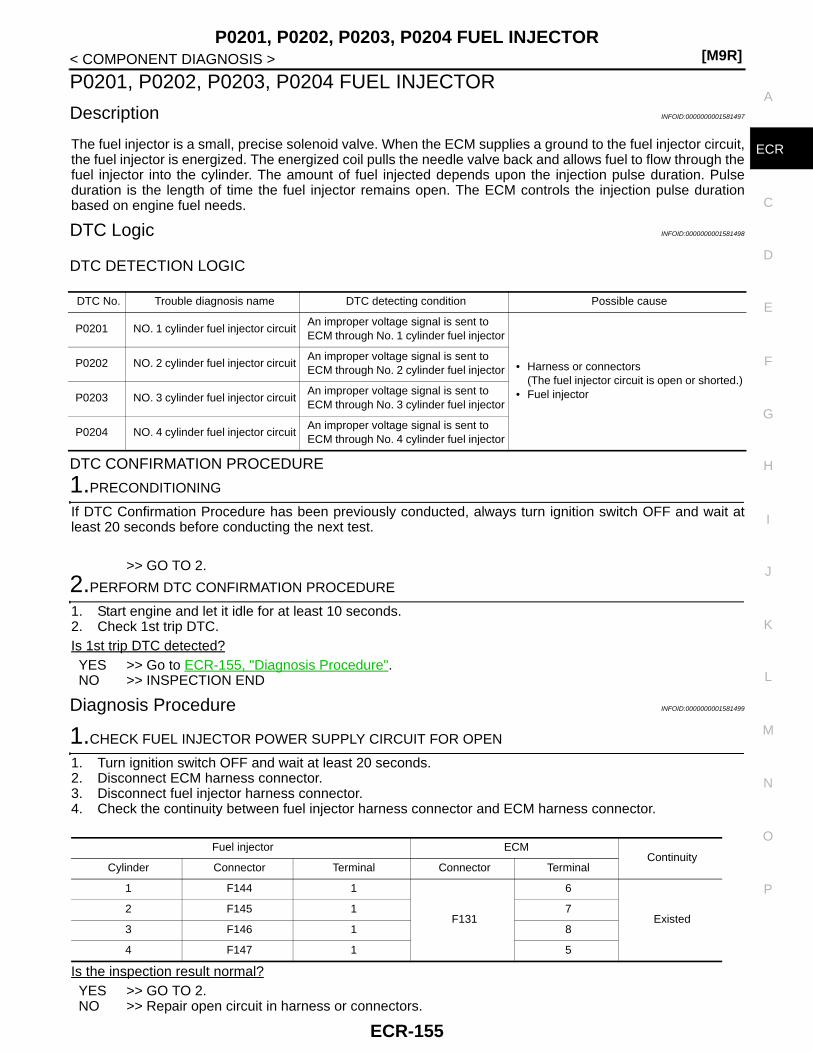
P0201, P0202, P0203, P0204 FUEL INJECTOR[M9R]
C
D
E
F
G
H
I
J
K
L
M
A
CR
N
P
O
< COMPONENT DIAGNOSIS >
E
P0201, P0202, P0203, P0204 FUEL INJECTOR
Description INFOID:0000000001581497
The fuel injector is a small, precise solenoid valve. When the ECM supplies a ground to the fuel injector circuit,the fuel injector is energized. The energized coil pulls the needle valve back and allows fuel to flow through thefuel injector into the cylinder. The amount of fuel injected depends upon the injection pulse duration. Pulseduration is the length of time the fuel injector remains open. The ECM controls the injection pulse durationbased on engine fuel needs.
DTC Logic INFOID:0000000001581498
DTC DETECTION LOGIC
DTC CONFIRMATION PROCEDURE
1.PRECONDITIONING
If DTC Confirmation Procedure has been previously conducted, always turn ignition switch OFF and wait atleast 20 seconds before conducting the next test.
>> GO TO 2.
2.PERFORM DTC CONFIRMATION PROCEDURE
1. Start engine and let it idle for at least 10 seconds.2. Check 1st trip DTC.Is 1st trip DTC detected?YES >> Go to ECR-155, "Diagnosis Procedure".NO >> INSPECTION END
Diagnosis Procedure INFOID:0000000001581499
1.CHECK FUEL INJECTOR POWER SUPPLY CIRCUIT FOR OPEN
1. Turn ignition switch OFF and wait at least 20 seconds.2. Disconnect ECM harness connector.3. Disconnect fuel injector harness connector.4. Check the continuity between fuel injector harness connector and ECM harness connector.
Is the inspection result normal?YES >> GO TO 2.NO >> Repair open circuit in harness or connectors.
DTC No. Trouble diagnosis name DTC detecting condition Possible cause
P0201 NO. 1 cylinder fuel injector circuitAn improper voltage signal is sent to ECM through No. 1 cylinder fuel injector
• Harness or connectors(The fuel injector circuit is open or shorted.)
• Fuel injector
P0202 NO. 2 cylinder fuel injector circuitAn improper voltage signal is sent to ECM through No. 2 cylinder fuel injector
P0203 NO. 3 cylinder fuel injector circuitAn improper voltage signal is sent to ECM through No. 3 cylinder fuel injector
P0204 NO. 4 cylinder fuel injector circuitAn improper voltage signal is sent to ECM through No. 4 cylinder fuel injector
Fuel injector ECMContinuity
Cylinder Connector Terminal Connector Terminal
1 F144 1
F131
6
Existed2 F145 1 7
3 F146 1 8
4 F147 1 5
ECR-155

[M9R]P0201, P0202, P0203, P0204 FUEL INJECTOR
< COMPONENT DIAGNOSIS >
2.CHECK FUEL INJECTOR OUTPUT SIGNAL CIRCUIT FOR OPEN
Check the continuity between fuel injector harness connector and ECM harness connector.
Is the inspection result normal?YES >> GO TO 3.NO >> Repair open circuit in harness or connectors.
3.CHECK FUEL INJECTOR CONTROL CIRCUIT FOR SHORT
Check the continuity between fuel injector harness connector and ECM harness connector.
Is the inspection result normal?YES >> GO TO 4.NO >> Repair short circuit in harness or connectors.
4.CHECK FUEL INJECTOR
Refer to ECR-156, "Component Inspection".Is the inspection result normal?YES >> GO TO 6.NO >> GO TO 5.
5.REPLACE FUEL INJECTOR
1. Replace malfunctioning fuel injector.2. Perform ECR-14, "INJECTOR ADJUSTMENT VALUE REGISTRATION : Special Repair Requirement".3. Perform ECR-14, "ZFC VALUE RESET : Special Repair Requirement".
>> INSPECTION END
6.CHECK INTERMITTENT INCIDENT
Refer to GI-39, "Intermittent Incident".
>> INSPECTION END
Component Inspection INFOID:0000000001581500
1.CHECK FUEL INJECTOR
Fuel injector ECMContinuity
Cylinder Connector Terminal Connector Terminal
1 F70 2
F131
2
Existed2 F71 2 3
3 F72 2 4
4 F73 2 1
Fuel injector ECMContinuity
Cylinder Connector Terminal Connector Terminal
1 F1441
F1312
Not existed
2 6
2 F1451
F1313
2 7
3 F1461
F1314
2 8
4 F1471
F1311
2 5
ECR-156

P0201, P0202, P0203, P0204 FUEL INJECTOR[M9R]
C
D
E
F
G
H
I
J
K
L
M
A
CR
N
P
O
< COMPONENT DIAGNOSIS >
E
1. Turn ignition switch OFF.2. Disconnect fuel injector harness connector.3. Check resistance between fuel injector terminals as follows.
Is the inspection result normal?YES >> INSPECTION ENDNO >> Replace malfunctioning fuel injector.
Terminals Resistance
1 and 2 178.2 - 181.8Ω
ECR-157

[M9R]P0225 APP SENSOR
< COMPONENT DIAGNOSIS >
P0225 APP SENSOR
Description INFOID:0000000001581501
The accelerator pedal position sensor is installed on the upper endof the accelerator pedal assembly. The sensors detect the accelera-tor pedal position and sends a signal to the ECM. The ECM uses thesignal to determine the amount of fuel to be injected.
DTC Logic INFOID:0000000001581502
DTC DETECTION LOGIC
DTC CONFIRMATION PROCEDURE
1.PRECONDITIONING
If DTC Confirmation Procedure has been previously conducted, always turn ignition switch OFF and wait atleast 20 seconds before conducting the next test.
>> GO TO 2.
2.PERFORM DTC CONFIRMATION PROCEDURE-I
1. Turn ignition switch ON and wait at least 5 seconds.2. Check 1st trip DTC.Is 1st trip DTC detected?YES >> Go to ECR-158, "Diagnosis Procedure".NO >> GO TO 3.
3.PERFORM DTC CONFIRMATION PROCEDURE-II
1. Depress accelerator pedal slowly spending 5 seconds, and then release it slowly spending 5 seconds.2. Check 1st trip DTC.Is 1st trip DTC detected?YES >> Go to ECR-158, "Diagnosis Procedure".NO >> INSPECTION END
Diagnosis Procedure INFOID:0000000001581503
1.CHECK GROUND CONNECTIONS
1. Turn ignition switch OFF and wait at least 20 seconds.2. Check ground connection E17. Refer to Ground inspection in GI-41, "Circuit Inspection".Is the inspection result normal?
PBIB1741E
DTC No. Trouble diagnosis name DTC detecting condition Possible cause
P0225
Accelerator pedal position sensor 1 circuit low input
An excessively low voltage from the sensor is sent to ECM.
• Harness or connectors(Accelerator pedal position sensor circuit is open or shorted.)
• Accelerator pedal position sensor(APP sensor 1 and 2)
Accelerator pedal position sensor 1 circuit high input
An excessively high voltage from the sensor is sent to ECM.
Accelerator pedal position sensor 1, 2 signal correlation
The correlation between APP sensor 1 signal and APP sensor 2 signal is out of the normal range.
ECR-158
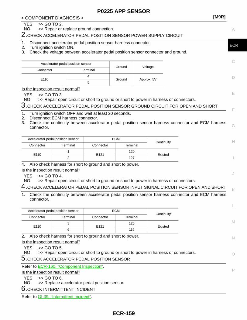
P0225 APP SENSOR[M9R]
C
D
E
F
G
H
I
J
K
L
M
A
CR
N
P
O
< COMPONENT DIAGNOSIS >
E
YES >> GO TO 2.NO >> Repair or replace ground connection.
2.CHECK ACCELERATOR PEDAL POSITION SENSOR POWER SUPPLY CIRCUIT
1. Disconnect accelerator pedal position sensor harness connector.2. Turn ignition switch ON.3. Check the voltage between accelerator pedal position sensor connector and ground.
Is the inspection result normal?YES >> GO TO 3.NO >> Repair open circuit or short to ground or short to power in harness or connectors.
3.CHECK ACCELERATOR PEDAL POSITION SENSOR GROUND CIRCUIT FOR OPEN AND SHORT
1. Turn ignition switch OFF and wait at least 20 seconds.2. Disconnect ECM harness connector.3. Check the continuity between accelerator pedal position sensor harness connector and ECM harness
connector.
4. Also check harness for short to ground and short to power. Is the inspection result normal?YES >> GO TO 4.NO >> Repair open circuit or short to ground or short to power in harness or connectors.
4.CHECK ACCELERATOR PEDAL POSITION SENSOR INPUT SIGNAL CIRCUIT FOR OPEN AND SHORT
1. Check the continuity between accelerator pedal position sensor harness connector and ECM harnessconnector.
2. Also check harness for short to ground and short to power. Is the inspection result normal?YES >> GO TO 5.NO >> Repair open circuit or short to ground or short to power in harness or connectors.
5.CHECK ACCELERATOR PEDAL POSITION SENSOR
Refer to ECR-160, "Component Inspection".Is the inspection result normal?YES >> GO TO 6.NO >> Replace accelerator pedal position sensor.
6.CHECK INTERMITTENT INCIDENT
Refer to GI-39, "Intermittent Incident".
Accelerator pedal position sensorGround Voltage
Connector Terminal
E1104
Ground Approx. 5V5
Accelerator pedal position sensor ECMContinuity
Connector Terminal Connector Terminal
E1101
E121120
Existed2 127
Accelerator pedal position sensor ECMContinuity
Connector Terminal Connector Terminal
E1103
E121126
Existed6 119
ECR-159
[M9R]P0225 APP SENSOR
< COMPONENT DIAGNOSIS >>> INSPECTION END
Component Inspection INFOID:0000000001581504
1.CHECK ACCELERATOR PEDAL POSITION SENSOR
1. Turn ignition switch OFF.2. Reconnect all harness connectors disconnected.3. Turn ignition switch ON.4. Check the voltage between ECM harness connector terminals as follows.
Is the inspection result normal?YES >> INSPECTION ENDNO >> Replace accelerator pedal assembly.
ECM ECMCondition Voltage
Connector Terminal Connector Terminal
E121
126(APP sensor 1)
E121
127(Sensor ground)
Accelerator pedal
Fully released 0.6 - 4.6 V
Fully depressed Less than 5 V
119(APP sensor 2)
120(Sensor ground)
Fully released More than 0.3 V
Fully depressed Less than 2.5 V
ECR-160

P0235 TC BOOST SENSOR[M9R]
C
D
E
F
G
H
I
J
K
L
M
A
CR
N
P
O
< COMPONENT DIAGNOSIS >
E
P0235 TC BOOST SENSOR
Description INFOID:0000000001581505
The turbocharger boost sensor detects pressure in the exit side of the charge air cooler. The sensor outputvoltage to the ECM increases as pressure increases.
DTC Logic INFOID:0000000001581506
DTC DETECTION LOGIC
DTC CONFIRMATION PROCEDURE
1.PRECONDITIONING
If DTC Confirmation Procedure has been previously conducted, always turn ignition switch OFF and wait atleast 20 seconds before conducting the next test.
>> GO TO 2.
2.PERFORM DTC CONFIRMATION PROCEDURE
1. Turn ignition switch ON and wait at least 10 seconds.2. Check 1st trip DTC.Is 1st trip DTC detected?YES >> Go to ECR-161, "Diagnosis Procedure".NO >> INSPECTION END
Diagnosis Procedure INFOID:0000000001581507
1.CHECK GROUND CONNECTIONS
1. Turn ignition switch OFF and wait at least 20 seconds.2. Check ground connection E17. Refer to Ground inspection in GI-41, "Circuit Inspection".Is the inspection result normal?YES >> GO TO 2.NO >> Repair or replace ground connection.
2.CHECK TUBOCHARGER BOOST SENSOR POWER SUPPLY CIRCUIT
1. Disconnect turbocharger boost sensor harness connector.2. Turn ignition switch ON.3. Check the voltage between turbocharger boost sensor harness connector and ground.
Is the inspection result normal?YES >> GO TO 3.NO >> Repair open circuit or short to ground or short to power in harness or connectors.
DTC No. Trouble diagnosis name DTC detecting condition Possible cause
P0235
Turbocharger boost sensor circuit low input
An excessively low voltage from the sensor is sent to ECM.
• Harness or connectors(Turbocharger boost sensor circuit is open or shorted.)
• Turbocharger boost sensor• Barometric pressure sensor (built-
into EC)
Turbocharger boost sensor circuit high input
An excessively high voltage from the sensor is sent to ECM.
Turbocharger boost sensor circuit range/performance
Rationally incorrect voltage from the sensor is sent to ECM, compared with the voltage signal from barometric pressure sensor (built-into ECM)
Turbocharger boost sensorGround Voltage
Connector Terminal
F91 1 Ground Approx. 5V
ECR-161

[M9R]P0235 TC BOOST SENSOR
< COMPONENT DIAGNOSIS >
3.CHECK TUBOCHARGER BOOST SENSOR GROUND CIRCUIT FOR OPEN AND SHORT
1. Turn ignition switch OFF and wait at least 20 seconds.2. Check the continuity between turbocharger boost sensor harness connector and ECM harness connector.
3. Also check harness for short to ground and short to power. Is the inspection result normal?YES >> GO TO 4.NO >> Repair open circuit or short to ground or short to power in harness or connectors.
4.CHECK TUBOCHARGER BOOST SENSOR INPUT SIGNAL CIRCUIT FOR OPEN AND SHORT
1. Check the continuity between turbocharger boost sensor harness connector and ECM harness connector.
2. Also check harness for short to ground and short to power. Is the inspection result normal?YES >> GO TO 5.NO >> Repair open circuit or short to ground or short to power in harness or connectors.
5.CHECK INTERMITTENT INCIDENT
Refer to GI-39, "Intermittent Incident".Is the inspection result normal?YES >> GO TO 6.NO >> Repair open circuit or short to ground or short to power in harness or connectors.
6.REPLACE TUBOCHARGER BOOST SENSOR
Replace turbocharger boost sensor.
>> GO TO 7.
7.PERFORM DTC CONFIRMATION PROCEDURE
Perform DTC CONFIRMATION PROCEDURE again. Refer to ECR-161, "DTC Logic".Is 1st trip DTC P0235 displayed again?YES >> GO TO 8.NO >> INSPECTION END
8.REPLACE ECM
1. Replace ECM.2. Go to ECR-12, "ADDITIONAL SERVICE WHEN REPLACING CONTROL UNIT : Special Repair Require-
ment".
>> INSPECTION END
Turbocharger boost sensor ECMContinuity
Connector Terminal Connector Terminal
F91 2 F131 17 Existed
Turbocharger boost sensor ECMContinuity
Connector Terminal Connector Terminal
F91 3 F131 18 Existed
ECR-162

P0263, P0266, P0269, P0272 FUEL INJECTOR[M9R]
C
D
E
F
G
H
I
J
K
L
M
A
CR
N
P
O
< COMPONENT DIAGNOSIS >
E
P0263, P0266, P0269, P0272 FUEL INJECTOR
Description INFOID:0000000001581508
The fuel injector is a small, precise solenoid valve. When the ECM supplies a ground to the fuel injector circuit,the coil in the fuel injector is energized. The energized coil pulls the needle valve back and amount of fuel toflow through the fuel injector into the cylinder. The amount of fuel injected depends upon the injection pulseduration.Pulse duration is the length of time the fuel injector remains open.The ECM controls the injectionpulse duration based on engine fuel needs.
DTC Logic INFOID:0000000001581509
DTC DETECTION LOGIC
DTC CONFIRMATION PROCEDURE
1.PRECONDITIONING
If DTC Confirmation Procedure has been previously conducted, always turn ignition switch OFF and wait atleast 20 seconds before conducting the next test.
>> GO TO 2.
2.PERFORM DTC CONFIRMATION PROCEDURE
1. Turn ignition switch ON and wait at least 10 seconds.2. Check 1st trip DTC.Is 1st trip DTC detected?YES >> Go to ECR-163, "Diagnosis Procedure".NO >> INSPECTION END
Diagnosis Procedure INFOID:0000000001581510
1.PERFORM INJECTOR ADJUSTAMENT VALUE REGSITRATION
1. Turn ignition switch OFF and wait at least 20 seconds.2. Turn ignition switch ON.3. Perform injector adjustment value registration for malfunctioning cylinder. Refer to ECR-14, "INJECTOR
ADJUSTMENT VALUE REGISTRATION : Special Repair Requirement".
>> GO TO 2.
2.CHECK DTC
Perform DTC CONFIRMATION PROCEDURE again.Refer to ECR-163, "DTC Logic".Is 1st trip DTC displayed again?YES >> Replace malfunctioning fuel injector.NO >> INSPECTION END
DTC No. Trouble diagnosis name DTC detecting condition Possible cause
P0263 NO. 1 cylinder fuel injector performanceThe zero fuel calibration value for fuel injector 1 is out of the specified range.
• Fuel injector
P0266 NO. 2 cylinder fuel injector performanceThe zero fuel calibration value for fuel injector 2 is out of the specified range.
P0269 NO. 3 cylinder fuel injector performanceThe zero fuel calibration value for fuel injector 3 is out of the specified range.
P0272 NO. 4 cylinder fuel injector performanceThe zero fuel calibration value for fuel injector 4 is out of the specified range.
ECR-163

[M9R]P0297 SERVICE REGENERATION
< COMPONENT DIAGNOSIS >
P0297 SERVICE REGENERATION
Description INFOID:0000000001581511
Service regeneration is performed with CONSULT-III to reduce particulate matter in DPF.For details, refer to ECR-16, "SERVICE REGENERATION : Description".
DTC Logic INFOID:0000000001581512
DTC DETECTION LOGIC
Diagnosis Procedure INFOID:0000000001581513
1.PERFORM SERVICE REGENERATION
Refer to ECR-17, "SERVICE REGENERATION : Special Repair Requirement".
>> GO TO 2.
2.ERASE DTC
With CONSULT-III1. Turn ignition switch ON.2. Select “SELF-DIAG RESULTS” mode with CONSULT-III.3. Touch “ERASE”.
With GST1. Turn ignition switch ON.2. Select Service $04 with GST.Is DTC erased?YES >> INSPECTION ENDNO >> GO TO 3.
3.CHECK INTERMITTENT INCIDENT
Refer to GI-39, "Intermittent Incident".
>> INSPECTION END
DTC No. Trouble diagnosis name DTC detecting condition Possible cause
P0297 Vehicle overspeed conditionECM received vehicle speed signal [more than 5km/h (3 MPH)] during service regeneration.
Vehicle was driven at a speed of 5km/h (3 MPH) or more during service regeneration.
ECR-164
P0300, P0301, P0302, P0303, P0304 MISFIRE[M9R]
C
D
E
F
G
H
I
J
K
L
M
A
CR
N
P
O
< COMPONENT DIAGNOSIS >
E
P0300, P0301, P0302, P0303, P0304 MISFIRE
DTC Logic INFOID:0000000001581514
DTC DETECTION LOGICWhen a misfire occurs, engine speed will fluctuate. If the engine speed fluctuates enough to cause the crank-shaft position sensor signal to vary, ECM can determine that a misfire is occurring.
DTC CONFIRMATION PROCEDURE
1.PRECONDITIONING
If DTC Confirmation Procedure has been previously conducted, always turn ignition switch OFF and wait atleast 20 seconds before conducting the next test.
>> GO TO 2.
2.PERFORM DTC CONFIRMATION PROCEDURE
1. Start engine and warm it up to normal operating temperature.2. Turn ignition switch OFF and wait at least 20 seconds.3. Restart engine and let it idle for about 30 seconds.4. Check 1st trip DTC.Is 1st trip DTC detected?YES >> Go to ECR-165, "Diagnosis Procedure".NO >> INSPECTION END
Diagnosis Procedure INFOID:0000000001581515
1.CHECK FOR LEAK
1. Start engine.2. Visually check the following for fuel leak.- Fuel line from fuel pump to fuel rail- Fuel rail- Fuel line from fuel rail to fuel injector.3. Check PCV hose connection.Is intake air leak detected?YES >> Discover air leak location and repair.NO >> GO TO 2.
2.CHECK FUEL INJECTOR-I
Refer to ECR-156, "Component Inspection".Is the inspection result normal?YES >> GO TO 3.NO >> GO TO 4.
3.CHECK FUEL INJECTOR-II
Sensor Input signal to ECM ECM function
Crankshaft position sensor Engine speed On board diagnosis of misfire
DTC No. Trouble diagnosis name DTC detecting condition Possible cause
P0300 Multiple cylinder misfire detected Multiple cylinder misfire.
• Poor compression• Incorrect fuel injector connection• Fuel injector• Lack of fuel
P0301 No.1 cylinder misfire detected No. 1 cylinder misfires.
P0302 No. 2 cylinder misfire detected No. 2 cylinder misfires.
P0303 No. 3 cylinder misfire detected No. 3 cylinder misfires.
P0304 No. 4 cylinder misfire detected No. 4 cylinder misfires.
ECR-165

[M9R]P0300, P0301, P0302, P0303, P0304 MISFIRE
< COMPONENT DIAGNOSIS >
With CONSULT-III1. Remove two fuel injectors.
NOTE:One is from malfunctioning cylinder and the other is from any cylinder other than the malfunctioning cylin-der.
2. Swap the two fuel injectors to the other cylinder.3. Reconnect ECM harness connector and fuel injector harness connectors.4. Turn ignition switch ON.5. Perform Injector Adjustment Value Registration. Refer to ECR-14, "INJECTOR ADJUSTMENT VALUE
REGISTRATION : Special Repair Requirement".6. Select “SELF DIAG RESULTS” mode with CONSULT-III.7. Touch “ERASE”.8. Perform DTC CONFIRMATION PROCEDURE again. Refer to ECR-165, "DTC Logic".9. Is DTC displayed for the other cylinder?
With GST1. Remove two fuel injectors.
NOTE:One is from malfunctioning cylinder and the other is from any cylinder other than the malfunctioning cylin-der.
2. Swap the two fuel injectors to the other cylinder.3. Reconnect ECM harness connector and fuel injector harness connector.4. Turn ignition switch ON.5. Perform Injector Adjustment Value Registration. Refer to ECR-14, "INJECTOR ADJUSTMENT VALUE
REGISTRATION : Special Repair Requirement".6. Select Service $04 with GST.7. Perform DTC CONFIRMATION PROCEDURE again. Refer to ECR-165, "DTC Logic".Is DTC displayed for the other cylinder?YES >> GO TO 4.NO >> GO TO 5.
4.REPLACE FUEL INJECOR
1. Replace fuel injector of malfunctioning cylinder.2. Perform Injector Adjustment Value Registration. Refer to ECR-14, "INJECTOR ADJUSTMENT VALUE
REGISTRATION : Special Repair Requirement".3. Perform Injector ZFC reset. Refer to ECR-14, "ZFC VALUE RESET : Special Repair Requirement".
>> INSPECTION END
5.CHECK COMPRESSION PRESSURE
Check compression pressure. Refer to EM-351, "Inspection".Is the inspection result normal?YES >> GO TO 6.NO >> Check pistons, piston rings, valves, valve seats and cylinder head gaskets.
6.CHECK INTERMITTENT INCIDENT
Refer to GI-39, "Intermittent Incident".
>> INSPECTION END
ECR-166

P0335 CKP SENSOR[M9R]
C
D
E
F
G
H
I
J
K
L
M
A
CR
N
P
O
< COMPONENT DIAGNOSIS >
E
P0335 CKP SENSOR
Description INFOID:0000000001581516
The crankshaft position (CKP) sensor is located on the cylinder block rear housing facing the gear teeth (cogs)of the signal plate.The ECM receives the voltage signal and detects the function of the engine revolution.
DTC Logic INFOID:0000000001581517
DTC DETECTION LOGIC
DTC CONFIRMATION PROCEDURE
1.PRECONDITIONING
If DTC Confirmation Procedure has been previously conducted, always turn ignition switch OFF and wait atleast 20 seconds before conducting the next test.
>> GO TO 2.
2.PERFORM DTC CONFIRMATION PROCEDURE
1. Start engine and let it idle for at least 10 seconds.If engine could not start, keep ignition switch at START position for 5 seconds.
2. Check 1st trip DTC.Is 1st trip DTC detected?YES >> Go to ECR-167, "Diagnosis Procedure".NO >> INSPECTION END
Diagnosis Procedure INFOID:0000000001581518
1.CHECK GROUND CONNECTIONS
1. Turn ignition switch OFF and wait at least 20 seconds.2. Check ground connection E17. Refer to Ground inspection in GI-41, "Circuit Inspection".Is the inspection result normal?YES >> GO TO 2.NO >> Repair or replace ground connection.
2.CHECK CKP SENSOR GROUND CIRCUIT FOR OPEN AND SHORT
1. Disconnect crankshaft position (CKP) sensor harness connector.2. Disconnect ECM harness connector.3. Check the continuity between CKP sensor harness connector and ECM harness connector.
4. Also check harness for short to ground and short to power. Is the inspection result normal?YES >> GO TO 3.NO >> Repair open circuit or short to ground or short to power in harness or connectors.
3.CHECK CKP SENSOR INPUT SIGNAL CIRCUIT FOR OPEN AND SHORT
DTC No. Trouble diagnosis name DTC detecting condition Possible cause
P0335
Crankshaft position sensor circuit
Crankshaft position sensor signal is not detected by ECM when engine is running.
• Harness or connectors(The sensor circuit is open or shorted.)
• Crankshaft position sensor• Signal plate
Crankshaft position sensor circuit range/performance
Crankshaft position sensor signal is not in the normal pattern when engine is running.
CKP sensor ECMContinuity
Connector Terminal Connector Terminal
F134 2 F132 50 Existed
ECR-167

[M9R]P0335 CKP SENSOR
< COMPONENT DIAGNOSIS >1. Check the continuity between CKP sensor harness connector and ECM harness connector.
2. Also check harness for short to ground and short to power. Is the inspection result normal?YES >> GO TO 4.NO >> Repair open circuit or short to ground or short to power in harness or connectors.
4.CHECK CKP SENSOR
Refer to ECR-168, "Component Inspection".Is the inspection result normal?YES >> GO TO 5.NO >> Replace crankshaft position sensor.
5.CHECK GEAR TOOTH
Visually check for chipping flywheel or signal plate gear tooth.Is the inspection result normal?YES >> GO TO 6.NO >> Replace flywheel or signal plate.
6.CHECK INTERMITTENT INCIDENT
Refer to GI-39, "Intermittent Incident".
>> INSPECTION END
Component Inspection INFOID:0000000001581519
1.CHECK CKP SENSOR
1. Turn ignition switch OFF.2. Disconnect CKP sensor harness connector.3. Check resistance between CKP sensor terminals as follows.
Is the inspection result normal?YES >> INSPECTION ENDNO >> Replace CKP sensor.
CKP sensor ECMContinuity
Connector Terminal Connector Terminal
F134 1 F132 49 Existed
Terminals Resistance
1 and 2 0.6 - 1.0 kΩ
ECR-168

P0340 CMP SENSOR[M9R]
C
D
E
F
G
H
I
J
K
L
M
A
CR
N
P
O
< COMPONENT DIAGNOSIS >
E
P0340 CMP SENSOR
Description INFOID:0000000001581520
The camshaft position (CMP) sensor senses the retraction with camshaft (left side) to identify a particular cyl-inder. The camshaft position (CMP) sensor senses the piston position.When the crankshaft position (CKP) sensor system becomes inoperative, the camshaft position (CMP) sensorprovides various controls of engine parts instead, utilizing timing of cylinder identification signals.The sensor consists of a permanent magnet and Hall IC.When engine is running, the high and low parts of the teeth cause the gap with the sensor to change.The changing gap cause the magnetic field near the sensor to change.Due to the changing magnetic field, the voltage from the sensor changes.
DTC Logic INFOID:0000000001581521
DTC DETECTION LOGIC
DTC CONFIRMATION PROCEDURE
1.PRECONDITIONING
If DTC Confirmation Procedure has been previously conducted, always turn ignition switch OFF and wait atleast 20 seconds before conducting the next test.
>> GO TO 2.
2.PERFORM DTC CONFIRMATION PROCEDURE
1. Start engine and let it idle for at least 10 seconds.2. Check 1st trip DTC.Is 1st trip DTC detected?YES >> Go to ECR-169, "Diagnosis Procedure".NO >> INSPECTION END
Diagnosis Procedure INFOID:0000000001581522
1.CHECK GROUND CONNECTIONS
1. Turn ignition switch OFF and wait at least 20 seconds.2. Check ground connection E17. Refer to Ground inspection in GI-41, "Circuit Inspection".Is the inspection result normal?YES >> GO TO 2.NO >> Repair or replace ground connection.
2.CHECK CMP SENSOR POWER SUPPLY CIRCUIT
1. Disconnect camshaft position (CMP) sensor harness connector.2. Turn ignition switch ON.3. Check the voltage between CMP sensor harness connector and ground.
Is the inspection result normal?YES >> GO TO 4.
DTC No. Trouble diagnosis name DTC detecting condition Possible cause
P0340
Camshaft position sensor circuit
Camshaft position sensor signal is not detected by ECM when engine is running.
• Harness or connectors(The sensor circuit is open or shorted.)
• Camshaft position sensor• Signal plate
Camshaft position sensor circuit range/performance
Camshaft position sensor signal is not in the normal pattern when engine is running.
CMP sensorGround Voltage
Connector Terminal
F138 3 Ground Battery voltage
ECR-169
[M9R]P0340 CMP SENSOR
< COMPONENT DIAGNOSIS >NO >> GO TO 3.
3.DETECT MALFUNCTIONING PART
Check the following.• Harness connector E7, F121• Harness for open or short between ECM and CMP sensor• Harness for open or short between IPDM E/R and CMP sensor
>> Repair open circuit or short to ground or short to power in harness or connectors.
4.CHECK CMP SENSOR GROUND CIRCUIT FOR OPEN AND SHORT
1. Turn ignition switch OFF and wait at least 20 seconds.2. Disconnect ECM harness connector.3. Check the continuity between CMP sensor harness connector and ECM harness connector.
4. Also check harness for short to ground and short to power. Is the inspection result normal?YES >> GO TO 5.NO >> Repair open circuit or short to ground or short to power in harness or connectors.
5.CHECK CMP SENSOR INPUT SIGNAL CIRCUIT FOR OPEN AND SHORT
1. Check the continuity between CMP sensor harness connector and ECM harness connector.
2. Also check harness for short to ground and short to power. Is the inspection result normal?YES >> GO TO 6.NO >> Repair open circuit or short to ground or short to power in harness or connectors.
6.CHECK CMP SENSOR
Refer to ECR-171, "Component Inspection".Is the inspection result normal?YES >> GO TO 7.NO >> Replace camshaft position sensor.
7.CHECK SPROCKET
Visually check for chipping signal plate gear tooth.Is the inspection result normal?YES >> GO TO 8.NO >> Repair or replace sprocket.
8.CHECK TIMING CHAIN
Refer to EM-384, "Exploded View".Is the inspection result normal?YES >> GO TO 9.NO >> Replace timing chain.
9.CHECK INTERMITTENT INCIDENT
Refer to GI-39, "Intermittent Incident".
CMP sensor ECMContinuity
Connector Terminal Connector Terminal
F138 1 F131 46 Existed
CMP sensor ECMContinuity
Connector Terminal Connector Terminal
F138 2 F131 48 Existed
ECR-170

P0340 CMP SENSOR[M9R]
C
D
E
F
G
H
I
J
K
L
M
A
CR
N
P
O
< COMPONENT DIAGNOSIS >
E
>> INSPECTION END
Component Inspection INFOID:0000000001581523
1.CHECK CAMSHAFT POSITION SENSOR
1. Turn ignition switch OFF.2. Disconnect camshaft position sensor harness connector.3. Check the resistance between camshaft position sensor terminals as follows.
Is the inspection result normal?YES >> INSPECTION ENDNO >> Replace camshaft position sensor.
Terminals Resistance
2 and 3 7.2 - 13.4 kΩ
1 and 2 More than 100 kΩ
1 and 3 More than 100 kΩ
ECR-171

[M9R]P0380 GLOW CONTROL SYSTEM
< COMPONENT DIAGNOSIS >
P0380 GLOW CONTROL SYSTEM
DTC Logic INFOID:0000000001581524
DTC DETECTION LOGIC
DTC CONFIRMATION PROCEDURE
1.PRECONDITIONING
If DTC Confirmation Procedure has been previously conducted, always turn ignition switch OFF and wait atleast 20 seconds before conducting the next test.
>> GO TO 2.
2.PERFORM DTC CONFIRMATION PROCEDURE
With CONSULT-III1. Turn ignition switch ON and select “DATA MONITOR” mode with CONSULT-III.2. Check the “ENG COOLAN TEMP” indication.
If indication is below 50 °C (122 °F), go to the next step.If indication is above 50 °C (122 °F), cool down engine and then go to the next step.
3. Wait at least 10 seconds.4. Check 1st trip DTC.
With GSTFollow the procedure “With CONSULT-III” above.Is 1st trip DTC detected?YES >> Go to ECR-172, "Diagnosis Procedure".NO >> INSPECTION END
Diagnosis Procedure INFOID:0000000001581525
1.CHECK GLOW CONTROL UNIT POWER SUPPLY CIRCUIT
1. Turn ignition switch OFF and wait at least 20 seconds.2. Disconnect glow control unit harness connector.3. Turn ignition switch ON.4. Check the voltage between glow control unit harness connector and ground.
Is the inspection result normal?YES >> GO TO 3.NO >> GO TO 2.
2.DETECT MALFUNCTIONING PART
Check the following.• 80A fusible link (letter N)• Harness for open and short between glow control unit and battery
>> Repair open circuit or short to ground or short to power in harness or connectors.
DTC No. Trouble diagnosis name DTC detecting condition Possible cause
P0380 Glow control unit circuitAn improper voltage signal is sent to ECM from glow control unit
• Harness or connectors(Glow plug control circuit is open or shorted.)(Glow control unit input signal circuit is open or shorted.)
• Glow plug• Glow control unit
Glow control unitGround Voltage
Connector Terminal
F94 4 Ground Battery voltage
ECR-172

P0380 GLOW CONTROL SYSTEM[M9R]
C
D
E
F
G
H
I
J
K
L
M
A
CR
N
P
O
< COMPONENT DIAGNOSIS >
E
3.CHECK GLOW CONTROL UNIT GROUND CIRCUIT FOR OPEN AND SHORT
1. Turn ignition switch OFF and wait at least 20 seconds.2. Disconnect ECM harness connector.3. Check the continuity between glow control unit harness connector and ECM harness connector.
4. Also check harness for short to ground and short to power. Is the inspection result normal?YES >> GO TO 4.NO >> Repair open circuit or short to ground or short to power in harness or connectors.
4.CHECK GLOW CONTROL UNIT INPUT SIGNAL CIRCUIT FOR OPEN AND SHORT
1. Check the continuity between glow control unit harness connector and ECM harness connector.
2. Also check harness for short to ground and short to power. Is the inspection result normal?YES >> GO TO 5.NO >> Repair open circuit or short to ground or short to power in harness or connectors.
5.CHECK GLOW PLUG CONTROL CIRCUIT FOR OPEN AND SHORT
1. Disconnect glow plug harness connector.2. Check the continuity between glow control unit harness connector and glow plug harness connector.
3. Also check harness for short to ground and short to power. Is the inspection result normal?YES >> GO TO 6.NO >> Repair open circuit or short to ground or short to power in harness or connectors.
6.CHECK GLOW PLUG
Refer to ECR-174, "Component Inspection".Is the inspection result normal?YES >> GO TO 7.NO >> Replace malfunctioning glow plug.
7.CHECK INTERMITTENT INCIDENT
Refer to GI-39, "Intermittent Incident".Is the inspection result normal?YES >> Replace glow control unit.NO >> Repair or replace.
Glow control unit ECMContinuity
Connector Terminal Connector Terminal
F94 5 F131 9 Existed
Glow control unit ECMContinuity
Connector Terminal Connector Terminal
F94 3 F132 53 Existed
Glow control unit Glow plugContinuity
Cylinder Connector Terminal Connector Terminal
1
F94
2 F95 1
Existed2 7 F96 1
3 1 F97 1
4 6 F98 1
ECR-173

[M9R]P0380 GLOW CONTROL SYSTEM
< COMPONENT DIAGNOSIS >
Component Inspection INFOID:0000000001581526
1.CHECK GLOW PLUG
1. Turn ignition switch OFF.2. Disconnect glow plug harness connector.3. Check resistance between glow plug terminals as follows.
Is the inspection result normal?YES >> INSPECTION ENDNO >> Replace malfunctioning glow plug.
Terminal Resistance
1 and engine ground 0.1 - 1.0 Ω [at 20°C (68°F)]
ECR-174
P0409 EGR VOLUME CONTROL VALVE CONTROL POSITION SENSOR[M9R]
C
D
E
F
G
H
I
J
K
L
M
A
CR
N
P
O
< COMPONENT DIAGNOSIS >
E
P0409 EGR VOLUME CONTROL VALVE CONTROL POSITION SENSOR
Description INFOID:0000000001581527
The EGR volume control valve consists of valve, actuator and position sensor, etc.The valve is installed inEGR passage, and operated by the actuator according to the output signal or the ECM. The actuator used DCmotor and it opens or closes the valve to change the EGR flow rate.The EGR volume control valve control position sensor consists of a permanent magnet and Hall IC. It sensesthe valve shaft movement and feeds the voltage signals to the ECM. The ECM judges the current openingangle of the valve from this signals, and controls the DC motor to make the valve opening angle in response todriving conditions.
DTC Logic INFOID:0000000001581528
DTC DETECTION LOGIC
DTC CONFIRMATION PROCEDURE
1.PRECONDITIONING
If DTC Confirmation Procedure has been previously conducted, always turn ignition switch OFF and wait atleast 20 seconds before conducting the next test.
>> GO TO 2.
2.PERFORM DTC CONFIRMATION PROCEDURE
1. Turn ignition switch ON and wait at least 10 seconds.2. Check 1st trip DTC.Is 1st trip DTC detected?YES >> Go to ECR-175, "Diagnosis Procedure".NO >> INSPECTION END
Diagnosis Procedure INFOID:0000000001581529
1.CHECK GROUND CONNECTIONS
1. Turn ignition switch OFF and wait at least 20 seconds.2. Check ground connection E17. Refer to Ground inspection in GI-41, "Circuit Inspection".Is the inspection result normal?YES >> GO TO 2.NO >> Repair or replace ground connection.
2.CHECK EGR VOLUME CONTROL VALVE CONTROL POSITION SENSOR POWER SUPPLY CIRCUIT
1. Disconnect EGR volume control valve harness connector.2. Turn ignition switch ON.3. Check the voltage between EGR volume control valve control position sensor harness connector and
ground.
Is the inspection result normal?
DTC No. Trouble diagnosis name DTC detecting condition Possible cause
P0409
EGR volume control valve control position sensor circuit low input
An excessively low voltage from the sensor is sent to ECM.
• Harness or connectors(EGR volume control valve control position sensor circuit is open or shorted.)
• EGR volume control valve control position sensor
EGR volume control valve control position sensor circuit high input
An excessively high voltage from the sensor is sent to ECM.
EGR volume control valve control position sensorGround Voltage
Connector Terminal
F99 4 Ground Approx. 5V
ECR-175

[M9R]P0409 EGR VOLUME CONTROL VALVE CONTROL POSITION SENSOR
< COMPONENT DIAGNOSIS >YES >> GO TO 3.NO >> Repair open circuit or short to ground or short to power in harness or connectors.
3.CHECK EGR VOLUME CONTROL VALVE CONTROL POSITION SENSOR GROUND CIRCUIT FOROPEN AND SHORT
1. Turn ignition switch OFF and wait at least 20 seconds.2. Disconnect ECM harness connector.3. Check the continuity between EGR volume control valve control position sensor harness connector and
ECM harness connector.
4. Also check harness for short to ground and short to power. Is the inspection result normal?YES >> GO TO 4.NO >> Repair open circuit or short to ground or short to power in harness or connectors.
4.CHECK EGR VOLUME CONTROL VALVE CONTROL POSITION SENSOR INPUT CIRCUIT FOR OPENAND SHORT
1. Check the continuity between EGR volume control valve control position sensor harness connector andECM harness connector.
2. Also check harness for short to ground and short to power. Is the inspection result normal?YES >> GO TO 5.NO >> Repair open circuit or short to ground or short to power in harness or connectors.
5.CHECK EGR VOLUME CONTROL VALVE CONTROL POSITION SENSOR
Refer to ECR-176, "Component Inspection".Is the inspection result normal?YES >> GO TO 7. NO >> GO TO 6.
6.REPLACE EGR VOLUME CONTROL VALVE
1. Replace EGR volume control valve.2. Perform ECR-15, "EGR VOLUME CONTROL VALVE CLOSED POSITION LEARNING VALUE CLEAR :
Special Repair Requirement".3. Perform ECR-15, "EGR VOLUME CONTROL VALVE CLOSED POSITION LEARNING : Special Repair
Requirement".
>> INSPECTIO END
7.CHECK INTERMITTENT INCIDENT
Refer to GI-39, "Intermittent Incident".
>> INSPECTIO END
Component Inspection INFOID:0000000001581530
1.CHECK EGR VOLUME CONTROL VALVE CONTROL POSITION SENSOR
1. Turn ignition switch OFF.
EGR volume control valve control position sensor ECMContinuity
Connector Terminal Connector Terminal
F99 2 F131 36 Existed
EGR volume control valve control position sensor ECMContinuity
Connector Terminal Connector Terminal
F99 6 F131 32 Existed
ECR-176

P0409 EGR VOLUME CONTROL VALVE CONTROL POSITION SENSOR[M9R]
C
D
E
F
G
H
I
J
K
L
M
A
CR
N
P
O
< COMPONENT DIAGNOSIS >
E
2. Disconnect EGR volume control valve harness connector.3. Check the resistance between EGR volume control valve terminals as follows.
Is the inspection result normal?YES >> INSPECTION ENDNO >> Replace EGR volume control valve.
Terminals Resistance
2 and 41 - 15 kΩ
2 and 6
ECR-177

[M9R]P0470 EXHAUST GAS PRESSURE SENSOR
< COMPONENT DIAGNOSIS >
P0470 EXHAUST GAS PRESSURE SENSOR
Description INFOID:0000000001581531
Exhaust gas pressure sensor is conected turbocharger with exhasut pressure tube. Exhaust gas pressuresensor measures the exhaust gas pressure and convers the pressure into a voltage signal. ECM receives thesignal and control turbocharger boost pressure.
DTC Logic INFOID:0000000001581532
DTC DETECTION LOGIC
DTC CONFIRMATION PROCEDURE
1.PRECONDITIONING
If DTC Confirmation Procedure has been previously conducted, always turn ignition switch OFF and wait atleast 20 seconds before conducting the next test.
>> GO TO 2.
2.PERFORM DTC CONFIRMATION PROCEDURE-I
1. Turn ignition switch ON and wait at least 10 seconds.2. Check 1st trip DTC.Is 1st trip DTC detected?YES >> Go to ECR-178, "Diagnosis Procedure".NO >> GO TO 3.
3.PERFORM DTC CONFIRMATION PROCEDURE-II
1. Start engine and let it idle at least 10 seconds.2. Check 1st trip DTC.Is 1st trip DTC detected?YES >> Go to ECR-178, "Diagnosis Procedure".NO >> INSPECTION END
Diagnosis Procedure INFOID:0000000001581533
1.CHECK GROUND CONNECTIONS
1. Turn ignition switch OFF and wait at least 20 seconds.2. Check ground connection E17. Refer to Ground inspection in GI-41, "Circuit Inspection".Is the inspection result normal?YES >> GO TO 2.NO >> Repair or replace ground connection.
2.CHECK EXHAUST GAS PRESSURE SENSOR POWER SUPPLY CIRCUIT
1. Disconnect exhaust gas pressure sensor harness connector.2. Turn ignition switch ON.3. Check the voltage between exhaust gas pressure sensor harness connector and ground.
DTC No. Trouble diagnosis name DTC detecting condition Possible cause
P0470
Exhaust gas pressure sensor circuit low input
An excessively low voltage from the sensor is sent to ECM. • Harness or connectors
(Exhaust gas pressure sensor circuit is open or shorted.)
• Exhaust gas pressure sensor• Barometric pressure sensor (built-into
EC)• Exhaust manifold and exhaust pipe
Exhaust gas pressure sensor circuit high input
An excessively high voltage from the sensor is sent to ECM.
Exhaust gas pressure sensor circuit range/performance
Rationally incorrect voltage from the sensor is sent to ECM, compared with the voltage signal from barometric pressure sensor (built-into ECM)
ECR-178
P0470 EXHAUST GAS PRESSURE SENSOR[M9R]
C
D
E
F
G
H
I
J
K
L
M
A
CR
N
P
O
< COMPONENT DIAGNOSIS >
EIs the inspection result normal?YES >> GO TO 3.NO >> Repair open circuit or short to ground or short to power in harness or connectors.
3.CHECK EXHAUST GAS PRESSURE SENSOR GROUND CIRCUIT FOR OPEN AND SHORT
1. Turn ignition switch OFF and wait at least 20 seconds.2. Check the continuity between exhaust gas pressure sensor harness connector and ECM harness connec-
tor.
3. Also check harness for short to ground and short to power. Is the inspection result normal?YES >> GO TO 4.NO >> Repair open circuit or short to ground or short to power in harness or connectors.
4.CHECK EXHAUST GAS PRESSURE SENSOR INPUT SIGNAL CIRCUIT FOR OPEN AND SHORT
1. Check the continuity between exhaust gas pressure sensor harness connector and ECM harness connec-tor.
2. Also check harness for short to ground and short to power. Is the inspection result normal?YES >> GO TO 5.NO >> Repair open circuit or short to ground or short to power in harness or connectors.
5.CHECK EXHAUST MANIFOLD AND EXHAUST PIPE
Check the exhaust manifold and exhaust pipe for clogging and cracks.Is the inspection result normal?YES >> GO TO 6.NO >> Repair or replace exhaust manifold or exhaust pipe.
6.CHECK INTERMITTENT INCIDENT
Refer to GI-39, "Intermittent Incident".Is the inspection result normal?YES >> Replace exhaust gas pressure sensor.NO >> Repair or replace.
Exhaust gas pressure sensorGround Voltage
Connector Terminal
F150 1 Ground Approx. 5V
Exhaust gas pressure sensor ECMContinuity
Connector Terminal Connector Terminal
F150 3 F131 16 Existed
Exhaust gas pressure sensor ECMContinuity
Connector Terminal Connector Terminal
F150 2 F131 20 Existed
ECR-179

[M9R]P0487 EGR VOLUME CONTROL VALVE
< COMPONENT DIAGNOSIS >
P0487 EGR VOLUME CONTROL VALVE
Description INFOID:0000000001581534
The EGR volume control valve consists of valve, actuator and position sensor, etc. The valve is installed inEGR passage, and operated by the actuator according to the output signal of the ECM. The actuator used DCmotor and it opens or closes the valve to change the EGR flow rate.The EGR volume control valve control position sensor consists of a permanent magnet and Hall IC. It sensesthe valve shaft movement and feeds the voltage signals to the ECM. The ECM judges the current openingangle of the valve from this signals, and controls the DC motor to make the valve opening angle in response todriving conditions,
DTC Logic INFOID:0000000001581535
DTC DETECTION LOGIC
DTC CONFIRMATION PROCEDURE
1.PRECONDITIONING
If DTC Confirmation Procedure has been previously conducted, always turn ignition switch OFF and wait atleast 20 seconds before conducting the next test.
>> GO TO 2.
2.PERFORM DTC CONFIRMATION PROCEDURE-I
1. Turn ignition switch ON and wait at least 10 seconds.2. Check 1st trip DTC.Is 1st trip DTC detected?YES >> Go to ECR-180, "Diagnosis Procedure".NO >> GO TO 3.
3.PERFORM DTC CONFIRMATION PROCEDURE-II
1. Turn ignition switch OFF and wait at least 20 seconds.2. Turn ignition switch ON and wait at least 10 seconds.3. Check 1st trip DTC.Is 1st trip DTC detected?YES >> Go to ECR-180, "Diagnosis Procedure".NO >> INSPECTION END
Diagnosis Procedure INFOID:0000000001581536
1.CHECK GROUND CONNECTIONS
1. Turn ignition switch OFF and wait at least 20 seconds.2. Check ground connection E17. Refer to Ground inspection in GI-41, "Circuit Inspection".Is the inspection result normal?YES >> GO TO 2.NO >> Repair or replace ground connection.
DTC No. Trouble diagnosis name DTC detecting condition Possible cause
P0487 EGR volume control valve circuit
ECM detects EGR volume control valve circuit is open.
• Harness or connectors(The EGR volume control valve control motor circuit is open or shorted.)
• EGR volume control valve
ECM detects EGR volume control valve circuit is short to ground.
ECM detects EGR volume control valve circuit is short to power.
ECM detects EGR volume control valve circuits are short to each other.
ECR-180

P0487 EGR VOLUME CONTROL VALVE[M9R]
C
D
E
F
G
H
I
J
K
L
M
A
CR
N
P
O
< COMPONENT DIAGNOSIS >
E
2.CHECK EGR VOLUME CONTROL VALVE DC MOTOR CIRCUIT
1. Disconnect EGR volume control valve harness connector.2. Disconnect ECM harness connector.3. Check harness continuity between the following terminals.
4. Also check harness for short to ground and short to power. Is the inspection result normal?YES >> GO TO 3.NO >> Repair open circuit or short to ground or short to power in harness or connectors.
3.CHECK EGR VOLUME CONTROL VALVE
Refer to ECR-181, "Component Inspection".Is the inspection result normal?YES >> GO TO 5.NO >> GO TO 4.
4.REPLACE EGR VOLUME CONTROL VALVE
1. Replace the EGR volume control valve.2. Perform ECR-15, "EGR VOLUME CONTROL VALVE CLOSED POSITION LEARNING VALUE CLEAR :
Special Repair Requirement".3. Perform ECR-15, "EGR VOLUME CONTROL VALVE CLOSED POSITION LEARNING : Special Repair
Requirement".
>> INSPECTIO END
5.CHECK INTERMITTENT INCIDENT
Refer to GI-39, "Intermittent Incident".
>> INSPECTION END
Component Inspection INFOID:0000000001581537
1.CHECK EGR VOLUME CONTROL VALVE CONTROL MOTOR
1. Turn ignition switch OFF.2. Disconnect EGR volume control valve harness connector.3. Check resistance between EGR volume control valve terminals as follows.
Is the inspection result normal?YES >> INSPECTION ENDNO >> Replace EGR volume control valve.
EGR volume control valve ECMContinuity
Connector Terminal Connector Terminal
F99
1
F132
95 Existed
96 Not existed
595 Not existed
96 Existed
Terminals Resistance
1 and 5 1 - 400 Ω
ECR-181

[M9R]P0488 EGR SYSTEM
< COMPONENT DIAGNOSIS >
P0488 EGR SYSTEM
DTC Logic INFOID:0000000001581538
DTC DETECTION LOGIC
DTC CONFIRMATION PROCEDURE
1.PRECONDITIONING
If DTC Confirmation Procedure has been previously conducted, always turn ignition switch OFF and wait atleast 20 seconds before conducting the next test.
>> GO TO 2.
2.PERFORM DTC CONFIRMATION PROCEDURE
1. Start engine and warm it up to normal operating temperature.2. Let engine idle for at least 10 seconds.3. Check 1st trip DTC.Is 1st trip DTC detected?YES >> Go to ECR-182, "Diagnosis Procedure".NO >> INSPECTION END
Diagnosis Procedure INFOID:0000000001581539
1.CHECK GROUND CONNECTIONS
1. Turn ignition switch OFF and wait at least 20 seconds.2. Check ground connection E17. Refer to Ground inspection in GI-41, "Circuit Inspection".Is the inspection result normal?YES >> GO TO 2.NO >> Repair or replace ground connection.
2.CHECK EGR VOLUME CONTROL VALVE INSTALLATION
Check that EGR volume control valve is installed properly.Is the inspection result normal?YES >> GO TO 3.NO >> Install EGR volume control valve properly.
3.CHECK EGR VOLUME CONTROL VALVE CONTROL MOTOR CIRCUIT
1. Check harness continuity between the following terminals.
2. Also check harness for short to ground and short to power.
DTC No. Trouble diagnosis name DTC detecting condition Possible cause
P0488EGR volume control valve function
• ECM detects EGR volume control valve is stuck closed.
• ECM detects EGR volume control valve is stuck open.
• EGR volume control valve closed position learning is not completed successfully.
• Harness or connectors(The EGR volume control valve circuit is open or shorted.)
• EGR volume control valve• EGR volume control valve installation• EGR passage clogged
EGR volume control valve ECMContinuity
Connector Terminal Connector Terminal
F99
2
F132
95 Existed
96 Not existed
695 Not existed
96 Existed
ECR-182

P0488 EGR SYSTEM[M9R]
C
D
E
F
G
H
I
J
K
L
M
A
CR
N
P
O
< COMPONENT DIAGNOSIS >
E
Is the inspection result normal?YES >> GO TO 4.NO >> Repair open circuit or short to ground or short to power in harness or connectors.
4.CHECK EGR VOLUME CONTROL VALVE VISUALLY
1. Remove the EGR volume control valve2. Check if foreign matter is caught between the EGR volume control valve and the housing.Is the inspection result normal?YES >> GO TO 5.NO >> Remove the foreign matter and clean the EGR volume control valve.
5.CHECK EGR PASSAGE
Check the following for clogging and cracks.• EGR tube• EGR hose• EGR coolerIs the inspection result normal?YES >> GO TO 6.NO >> Repair or replace EGR passage.
6.CHECK EGR VOLUME CONTROL VALVE
Refer to ECR-181, "Component Inspection".Is the inspection result normal?YES >> GO TO 7.NO >> GO TO 8.
7.CHECK EGR VOLUME CONTROL VALVE CONTROL POSITION SENSOR
Refer to ECR-176, "Component Inspection".Is the inspection result normal?YES >> GO TO 9.NO >> GO TO 8.
8.REPLACE EGR VOLUME CONTROL VALVE
1. Replace the EGR volume control valve.2. Perform ECR-15, "EGR VOLUME CONTROL VALVE CLOSED POSITION LEARNING VALUE CLEAR :
Special Repair Requirement".3. Perform ECR-15, "EGR VOLUME CONTROL VALVE CLOSED POSITION LEARNING : Special Repair
Requirement".
>> INSPECTIO END
9.CHECK INTERMITTENT INCIDENT
Refer to GI-39, "Intermittent Incident".
>> INSPECTIO END
ECR-183

[M9R]P0500 VSS
< COMPONENT DIAGNOSIS >
P0500 VSS
Description INFOID:0000000001581540
The vehicle speed signal is sent to the combination meter from the “ABS actuator and electric unit (controlunit)” by CAN communication line. The combination meter then sends a signal to the ECM by CAN communi-cation line.
DTC Logic INFOID:0000000001581541
DTC DETECTION LOGIC
DTC CONFIRMATION PROCEDURE
1.PRECONDITIONING
If DTC Confirmation Procedure has been previously conducted, always turn ignition switch OFF and wait atleast 20 seconds before conducting the next test.
>> GO TO 2.
2.PERFORM DTC CONFIRMATION PROCEDURE
1. Start engine and let it idle for at least 1 minutes.2. Check 1st trip DTC.Is 1st trip DTC detected?YES >> Go to ECR-184, "Diagnosis Procedure".NO >> INSPECTION END
Diagnosis Procedure INFOID:0000000001581542
1.CHECK CAN COMMUNICATION LINE
Refer to LAN-28, "CAN Communication Signal Chart".Is the inspection result normal?YES >> GO TO 2.NO >> Repair or replace
2.CHECK DTC WITH “ABS ACTUATOR AND ELECTRIC UNIT (CONTROL UNIT)”
Refer to BRC-17, "CONSULT-III Function (ABS)" (without ESP) or BRC-95, "CONSULT-III Function (ABS)"(with ESP).Is the inspection result normal?YES >> GO TO 3.NO >> Repair or replace.
3.CHECK COMBINATION METER
Refer to MWI-27, "CONSULT-III Function (METER/M&A)".
>> INSPECTION END
DTC No. Trouble diagnosis name DTC detecting condition Possible cause
P0500 Vehicle speed signalVehicle speed signal is more than the specified range
• Harness or connectors(The CAN communication line is open or shorted)
• Harness or connectors(The vehicle speed signal circuit is open or shorted)
• Wheel sensor• Combination meter• ABS actuator and electric unit (control unit)
ECR-184

P0530 REFRIGERANT PRESSURE SENSOR[M9R]
C
D
E
F
G
H
I
J
K
L
M
A
CR
N
P
O
< COMPONENT DIAGNOSIS >
E
P0530 REFRIGERANT PRESSURE SENSOR
Description INFOID:0000000001581543
The refrigerant pressure sensor is installed at the condenser of the air conditioner system. The sensor uses anelectrostatic volume pressure transducer to convert refrigerant pressure to voltage. The voltage signal is sentto ECM, and ECM controls cooling fan system.
DTC Logic INFOID:0000000001581544
DTC DETECTION LOGIC
DTC CONFIRMATION PROCEDURE
1.PRECONDITIONING
If DTC Confirmation Procedure has been previously conducted, always turn ignition switch OFF and wait atleast 20 seconds before conducting the next test.
>> GO TO 2.
2.PERFORM DTC CONFIRMATION PROCEDURE
1. Turn ignition switch ON and wait at least 10 seconds.2. Check 1st trip DTC.Is 1st trip DTC detected?YES >> Go to ECR-185, "Diagnosis Procedure".NO >> INSPECTION END
Diagnosis Procedure INFOID:0000000001581545
1.CHECK GROUND CONNECTIONS
1. Turn ignition switch OFF and wait at least 20 seconds.2. Check ground connection E17. Refer to Ground inspection in GI-41, "Circuit Inspection".Is the inspection result normal?YES >> GO TO 2.NO >> Repair or replace ground connection.
2.CHECK REFRIGERANT PRESSURE SENSOR POWER SUPPLY CIRCUIT
1. Disconnect refrigerant pressure sensor harness connector.2. Turn ignition switch ON.3. Check the voltage between refrigerant pressure sensor connector and ground.
Is the inspection result normal?YES >> GO TO 4.NO >> GO TO 3.
3.DETECT MALFUNCTIONING PART
Check the following.• Harness connector E6, F123
DTC No. Trouble diagnosis name DTC detecting condition Possible cause
P0530
Refrigerant pressure sensor circuit low input
An excessively low voltage from the sensor is sent to ECM.
• Harness or connectors(Refrigerant pressure sensor circuit is open or shorted.)
• Refrigerant pressure sensorRefrigerant pressure sensor circuit high input
An excessively high voltage from the sensor is sent to ECM.
Refrigerant pressure sensorGround Voltage
Connector Terminal
E50 3 Ground Approx. 5V
ECR-185

[M9R]P0530 REFRIGERANT PRESSURE SENSOR
< COMPONENT DIAGNOSIS >• Harness for open or short between ECM and refrigerant pressure sensor
>> Repair open circuit or short to ground or short to power in harness or connectors.
4.CHECK REFRIGERANT PRESSURE SENSOR GROUND CIRCUIT FOR OPEN AND SHORT
1. Turn ignition switch OFF and wait at least 20 seconds.2. Disconnect ECM harness connector.3. Check the continuity between refrigerant pressure sensor harness connector and ECM harness connec-
tor.
4. Also check harness for short to ground and short to power. Is the inspection result normal?YES >> GO TO 6.NO >> GO TO 5.
5.DETECT MALFUNCTIONING PART
Check the following.• Harness connector E6, F123• Harness for open or short between ECM and refrigerant pressure sensor
>> Repair open circuit or short to ground or short to power in harness or connectors.
6.CHECK REFRIGERANT PRESSURE SENSOR INPUT SIGNAL CIRCUIT FOR OPEN AND SHORT
1. Check the continuity between refrigerant pressure sensor harness connector and ECM harness connec-tor.
2. Also check harness for short to ground and short to power. Is the inspection result normal?YES >> GO TO 8.NO >> GO TO 7.
7.DETECT MALFUNCTIONING PART
Check the following.• Harness connector E6, F123• Harness for open or short between ECM and refrigerant pressure sensor
>> Repair open circuit or short to ground or short to power in harness or connectors.
8.CHECK INTERMITTENT INCIDENT
Refer to GI-39, "Intermittent Incident".Is the inspection result normal?YES >> Replace refrigerant pressure sensor.NO >> Repair or replace.
Refrigerant pressure sensor ECMContinuity
Connector Terminal Connector Terminal
E50 1 F131 35 Existed
Refrigerant pressure sensor ECMContinuity
Connector Terminal Connector Terminal
E50 2 F131 31 Existed
ECR-186

P0544 EGT SENSOR 1[M9R]
C
D
E
F
G
H
I
J
K
L
M
A
CR
N
P
O
< COMPONENT DIAGNOSIS >
E
P0544 EGT SENSOR 1
Description INFOID:0000000001581546
The exhaust gas temperature sensor 1 is used to detect the exhaust gas temperature before turbocharger.The sensor modifies a voltage signal from the ECM. The modified signal returns to the ECM as the exhaustgas temperature input. The sensor uses a thermistor which is sensitive to the change in temperature. Theelectrical resistance of the thermistor decreases as temperature increases.
DTC Logic INFOID:0000000001581547
DTC DETECTION LOGICIf DTC P0544 is displayed with DTC P0115, first perform the trouble diagnosis for DTC P0115. Refer toECR-132, "DTC Logic".
DTC CONFIRMATION PROCEDURE
1.PRECONDITIONING
If DTC Confirmation Procedure has been previously conducted, always turn ignition switch OFF and wait atleast 20 seconds before conducting the next test.
>> GO TO 2.
2.PERFORM DTC CONFIRMATION PROCEDURE-I
1. Turn ignition switch ON and wait at least 10 seconds.2. Check 1st trip DTC.Is 1st trip DTC detected?YES >> Go to ECR-187, "Diagnosis Procedure".NO >> GO TO 3.
3.PERFORM DTC CONFIRMATION PROCEDURE-II
1. Start engine and drive vehicle under the following conditions for at least 10 seconds.- Gear position: 3rd position- Vehicle speed: Accelerates from 55km/h (34 MPH) to 70 km/h (43 MPH)2. Check 1st trip DTC.Is 1st trip DTC detected?YES >> Go to ECR-187, "Diagnosis Procedure".NO >> INSPECTION END
Diagnosis Procedure INFOID:0000000001581548
1.CHECK GROUND CONNECTIONS
1. Turn ignition switch OFF and wait at least 20 seconds.2. Check ground connection E17. Refer to Ground inspection in GI-41, "Circuit Inspection".Is the inspection result normal?YES >> GO TO 2.NO >> Repair or replace ground connection.
2.CHECK EXHAUST GAS TEMPERATURE SENSOR 1 POWER SUPPLY CIRCUIT
1. Disconnect exhaust gas temperature sensor 1 harness connector.2. Turn ignition switch ON.3. Check the voltage between exhaust gas temperature sensor 1 harness connector and ground.
DTC No. Trouble diagnosis name DTC detecting condition Possible cause
P0544
Exhaust gas temperature sensor 1 circuit low input
An excessively low voltage from the sensor is sent to ECM.
• Harness or connectors(Exhaust gas temperature sensor 1 circuit is open or shorted.)
• Exhaust gas temperature sensor 1Exhaust gas temperature sensor 1 circuit high input
An excessively high voltage from the sensor is sent to ECM.
ECR-187
[M9R]P0544 EGT SENSOR 1
< COMPONENT DIAGNOSIS >
Is the inspection result normal?YES >> GO TO 3.NO >> Repair open circuit or short to ground or short to power in harness or connectors.
3.CHECK EXHAUST GAS TEMPERATURE SENSOR 1 GROUND CIRCUIT FOR OPEN AND SHORT
1. Turn ignition switch OFF and wait at least 20 seconds.2. Check the continuity between exhaust gas temperature sensor 1 harness connector and ECM harness
connector.
3. Also check harness for short to ground and short to power. Is the inspection result normal?YES >> GO TO 4.NO >> Repair open circuit or short to ground or short to power in harness or connectors.
4.CHECK INTERMITTENT INCIDENT
Refer to GI-39, "Intermittent Incident".Is the inspection result normal?YES >> Replace exhaust gas temperature sensor 1.NO >> Repair or replace.
Exhaust gas temperature sensor 1Ground Voltage
Connector Terminal
F142 1 Ground Approx. 5V
Exhaust gas temperature sensor 1 ECMContinuity
Connector Terminal Connector Terminal
F142 2 F131 10 Existed
ECR-188

P0560 BATTERY VOLTAGE[M9R]
C
D
E
F
G
H
I
J
K
L
M
A
CR
N
P
O
< COMPONENT DIAGNOSIS >
E
P0560 BATTERY VOLTAGE
DTC Logic INFOID:0000000001581549
DTC DETECTION LOGIC
DTC CONFIRMATION PROCEDURE
1.PRECONDITIONING
If DTC Confirmation Procedure has been previously conducted, always turn ignition switch OFF and wait atleast 20 seconds before conducting the next test.
>> GO TO 2.
2.PERFORM DTC CONFIRMATION PROCEDURE
1. Turn ignition switch ON and wait at least 30 seconds.2. Check 1st trip DTC.Is 1st trip DTC detected?YES >> Go to ECR-189, "Diagnosis Procedure".NO >> INSPECTION END
Diagnosis Procedure INFOID:0000000001581550
1.CHECK BATTERY VOLTAGE
1. Turn ignition switch ON.2. Check battery voltage.
Is the inspection result normal?YES >> GO TO 2.NO >> Recharge the battery.
2.CHECK BATTERY TERMINALS
1. Turn ignition switch OFF and wait at least 20 seconds.2. Check battery terminals condition.Is the inspection result normal?YES >> GO TO 3.NO >> Repair the battery terminals.
3.CHECK BATTERY AND ALTERNATOR
Check that the proper type of battery and type of alternator are installed.Refer to, PG-116, "Battery" and CHG-35, "Alternator".Is the inspection result normal?YES >> GO TO 4.NO >> Replace with a proper one.
4.CHECK ECM POWER SUPPLY CIRCUIT-I
Check the voltage between ECM harness connector and ground.
DTC No. Trouble diagnosis name DTC detecting condition Possible cause
P0560 Battery voltage
An excessively low voltage from the battery is sent to ECM.
• Harness or connectors(ECM power supply circuit is open or shorted.)
• Battery• Battery terminal• Alternator• IPDM E/R
An excessively high voltage from the battery is sent to ECM.
An improper voltage is sent to ECM through battery
Voltage: Above 11V
ECR-189
[M9R]P0560 BATTERY VOLTAGE
< COMPONENT DIAGNOSIS >
Is the inspection result normal?YES >> GO TO 5.NO >> GO TO 7.
5.CHECK ECM POWER SUPPLY CIRCUIT-II
1. Disconnect ECM harness connector.2. Disconnect IPDM E/R harness connector E11.3. Check the continuity between ECM harness connector and IPDM E/R harness connector.
4. Also check harness for short to ground and short to power.Is the inspection result normal?YES >> GO TO 9.NO >> GO TO 6.
6.DETECT MALFUNCTIONING PART
Check the following.• Harness or connectors E7, F121• Harness for open or short between ECM and IPDM E/R
>> Repair open circuit or short to ground or short to power in harness or connectors.
7.CHECK ECM POWER SUPPLY CIRCUIT-III
1. Disconnect ECM harness connector.2. Disconnect IPDM E/R harness connector E11.3. Check the continuity between ECM harness connector and IPDM E/R harness connector.
4. Also check harness for short to ground and short to power.Is the inspection result normal?YES >> GO TO 9.NO >> GO TO 8.
8.DETECT MALFUNCTIONING PART
Check the following.• Harness or connectors E7, F121• Harness for open or short between ECM and IPDM E/R
>> Repair open circuit or short to ground or short to power in harness or connectors.
9.CHECK 20A FUSE
1. Disconnect 20A fuse (No. 52) from IPDM E/R.2. Check 20A fuse.Is the inspection result normal?
ECMGround Voltage
Connector Terminal
F132 62 Ground Battery voltage
ECM IPDM E/RContinuity
Connector Terminal Connector Terminal
E13293
E11 9 Existed94
ECM IPDM E/RContinuity
Connector Terminal Connector Terminal
F132 62 E11 15 Existed
ECR-190
P0560 BATTERY VOLTAGE[M9R]
C
D
E
F
G
H
I
J
K
L
M
A
CR
N
P
O
< COMPONENT DIAGNOSIS >
E
YES >> GO TO 10.NO >> Replace 20A fuse.
10.CHECK GROUND CONNECTION
Check ground connection E17. Refer to Ground Inspection in GI-41, "Circuit Inspection".Is the inspection result normal?YES >> GO TO 11.NO >> Repair or replace ground connection.
11.CHECK ECM GROUND CIRCUIT FOR OPEN AND SHORT
1. Check the continuity between ECM harness connector and ground.
2. Also check harness for short to power.Is the inspection result normal?YES >> GO TO 12.NO >> Repair open circuit or short power in harness or connectors.
12.CHECK INTERMITTENT INCIDENT
Refer to GI-39, "Intermittent Incident".Is the inspection result normal?YES >> Replace IPDM E/R.NO >> Repair or replace.
ECMGround Continuity
Connector Terminal
E121
123
Ground Existed124
125
128
ECR-191

[M9R]P0564 ASCD STEERING SWITCH
< COMPONENT DIAGNOSIS >
P0564 ASCD STEERING SWITCH
Description INFOID:0000000001581551
ASCD steering switch has variant values of electrical resistance for each button. ECM reads voltage variationof switch, and determines which button is operated.
DTC Logic INFOID:0000000001581552
DTC DETECTION LOGIC
DTC CONFIRMATION PROCEDURE
1.PRECONDITIONING
If DTC Confirmation Procedure has been previously conducted, always turn ignition switch OFF and wait atleast 20 seconds before conducting the next test.
>> GO TO 2.
2.PERFORM DTC CONFIRMATION PROCEDURE
1. Turn ignition switch ON and wait at least 10 seconds.2. Press MAIN switch for at least 10 seconds, then release it and wait at least 10 seconds.3. Press CANCEL switch for at least 10 seconds, then release it and wait at least 10 seconds.4. Press RESUME/ACCELERATE switch for at least 10 seconds, then release it and wait at least 10 sec-
onds.5. Press SET/COAST switch for at least 10 seconds, then release it and wait at least 10 seconds.6. Check 1st trip DTC.Is 1st trip DTC detected?YES >> Go to ECR-192, "Diagnosis Procedure".NO >> INSPECTION END
Diagnosis Procedure INFOID:0000000001581553
1.CHECK GROUND CONNECTIONS
1. Turn ignition switch OFF and wait at least 20 seconds.2. Check ground connection E17. Refer to Ground inspection in GI-41, "Circuit Inspection".Is the inspection result normal?YES >> GO TO 2.NO >> Repair or replace ground connection.
2.CHECK ASCD STEERING SWITCH CIRCUIT
1. Turn ignition switch ON.2. Check the voltage between ECM harness connector terminals as follows.
DTC No. Trouble diagnosis name DTC detecting condition Possible cause
P0564 ASCD steering switch circuit
An excessively high voltage signal from the ASCD steering switch is sent to ECM.
• Harness or connectors(The switch circuit is open or shorted.)
• ASCD steering switch
ECM detects that input signal from the ASCD steering switch is out of the specified range.
ECM detects that the ASCD steering switch is stuck ON.
ECR-192

P0564 ASCD STEERING SWITCH[M9R]
C
D
E
F
G
H
I
J
K
L
M
A
CR
N
P
O
< COMPONENT DIAGNOSIS >
E
Is the inspection result normal?YES >> GO TO 8.NO >> GO TO 3.
3.CHECK ASCD STEERING SWITCH GROUND CIRCUIT FOR OPEN AND SHORT
1. Turn ignition switch OFF and wait at least 20 seconds.2. Disconnect combination switch harness connector.3. Disconnect ECM harness connector.4. Check the continuity between combination switch (spiral cable) and ECM harness connector.
5. Also check harness for short to ground and short to power. Is the inspection result normal?YES >> GO TO 5.NO >> GO TO 4.
4.DETECT MALFUNCTIONING PART
• Harness connectors M77, E105• Combination switch (spiral cable)• Harness for open or short between ECM and combination switch
>> Repair open circuit or short to ground or short to power in harness or connectors.
5.CHECK ASCD STEERING SWITCH INPUT SIGNAL CIRCUIT FOR OPEN AND SHORT
1. Check the continuity between combination switch (spiral cable) and ECM harness connector.
2. Also check harness for short to ground and short to power. Is the inspection result normal?YES >> GO TO 7.NO >> GO TO 6.
6.DETECT MALFUNCTIONING PART
• Harness connectors M77, E105• Combination switch (spiral cable)• Harness for open or short between ECM and combination switch
>> Repair open circuit or short to ground or short to power in harness or connectors.
7.CHECK ASCD STEERING SWITCH
Refer to ECR-194, "Component Inspection".
(+) (−)Condition Voltage
Connector Terminal Connector Terminal
E121110
(ASCD steering switch signal)
E121111
(ASCD steering switch ground)
MAIN switch: Pressed Approx. 0V
CANSEL switch: Pressed Approx. 1V
SET/COAST switch: Pressed Approx. 2V
RESUME/ACCELERATE switch: Pressed Approx. 3V
All ASCD steering switches: Released Approx. 4V
Combination switch (spiral cable) ECMContinuity
Connector Terminal Connector Terminal
— 15 E121 111 Existed
Combination switch (spiral cable) ECMContinuity
Connector Terminal Connector Terminal
— 14 E121 110 Existed
ECR-193

[M9R]P0564 ASCD STEERING SWITCH
< COMPONENT DIAGNOSIS >Is the inspection result normal?YES >> GO TO 8.NO >> Replace ASCD steering switch.
8.CHECK INTERMITTENT INCIDENT
Refer to GI-39, "Intermittent Incident".
>> INSPECTION END
Component Inspection INFOID:0000000001581554
1.CHECK ASCD STEERING SWITCH
1. Disconnect combination switch (spiral cable) harness connector M352.2. Check the continuity between combination switch harness connector terminals under following conditions.
Is the inspection result normal?YES >> INSPECTION ENDNO >> Replace ASCD steering switch
Combination meterCondition Resistance
Connector Terminals
M35214 and 15
(Combination switch)
MAIN switch: Pressed Approx. 0 Ω
CANCEL switch: Pressed Approx. 250 Ω
SET/COAST switch: Pressed Approx. 660 Ω
RESUME/ACCELERATE switch: Pressed Approx. 1,480 Ω
All ASCD steering switches: Released Approx. 4,000 Ω
ECR-194
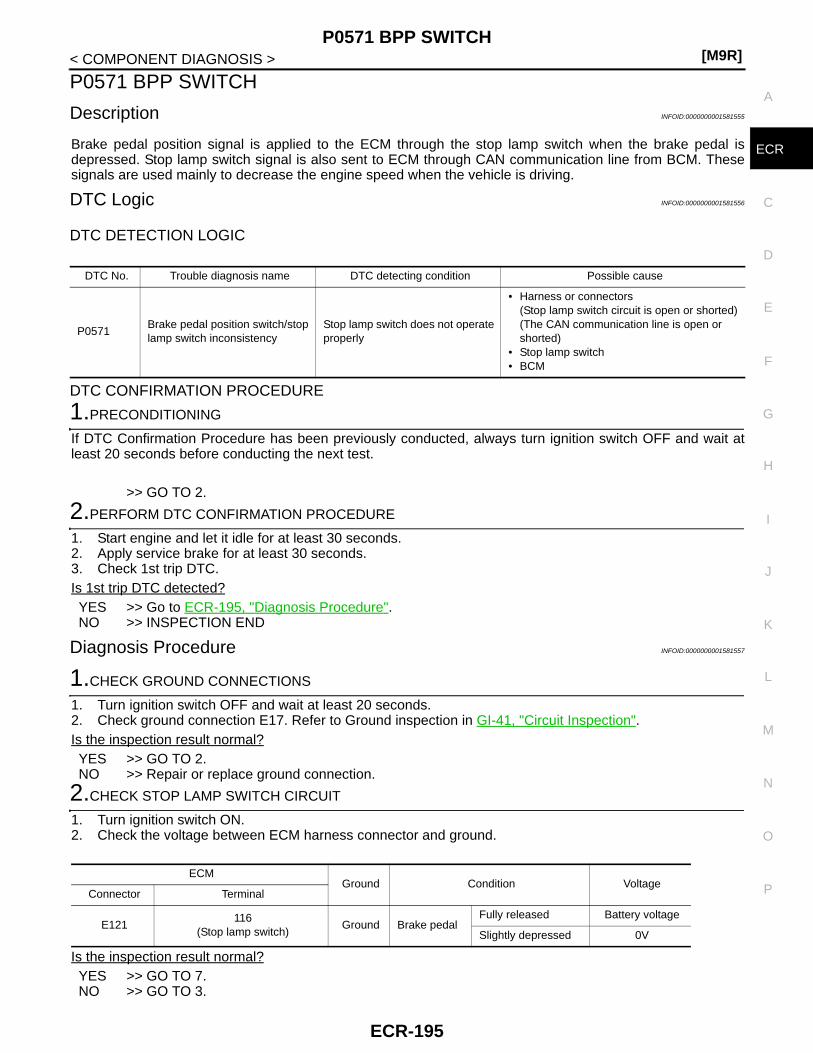
P0571 BPP SWITCH[M9R]
C
D
E
F
G
H
I
J
K
L
M
A
CR
N
P
O
< COMPONENT DIAGNOSIS >
E
P0571 BPP SWITCH
Description INFOID:0000000001581555
Brake pedal position signal is applied to the ECM through the stop lamp switch when the brake pedal isdepressed. Stop lamp switch signal is also sent to ECM through CAN communication line from BCM. Thesesignals are used mainly to decrease the engine speed when the vehicle is driving.
DTC Logic INFOID:0000000001581556
DTC DETECTION LOGIC
DTC CONFIRMATION PROCEDURE
1.PRECONDITIONING
If DTC Confirmation Procedure has been previously conducted, always turn ignition switch OFF and wait atleast 20 seconds before conducting the next test.
>> GO TO 2.
2.PERFORM DTC CONFIRMATION PROCEDURE
1. Start engine and let it idle for at least 30 seconds.2. Apply service brake for at least 30 seconds.3. Check 1st trip DTC.Is 1st trip DTC detected?YES >> Go to ECR-195, "Diagnosis Procedure".NO >> INSPECTION END
Diagnosis Procedure INFOID:0000000001581557
1.CHECK GROUND CONNECTIONS
1. Turn ignition switch OFF and wait at least 20 seconds.2. Check ground connection E17. Refer to Ground inspection in GI-41, "Circuit Inspection".Is the inspection result normal?YES >> GO TO 2.NO >> Repair or replace ground connection.
2.CHECK STOP LAMP SWITCH CIRCUIT
1. Turn ignition switch ON.2. Check the voltage between ECM harness connector and ground.
Is the inspection result normal?YES >> GO TO 7.NO >> GO TO 3.
DTC No. Trouble diagnosis name DTC detecting condition Possible cause
P0571Brake pedal position switch/stop lamp switch inconsistency
Stop lamp switch does not operate properly
• Harness or connectors(Stop lamp switch circuit is open or shorted)(The CAN communication line is open or shorted)
• Stop lamp switch• BCM
ECMGround Condition Voltage
Connector Terminal
E121116
(Stop lamp switch)Ground Brake pedal
Fully released Battery voltage
Slightly depressed 0V
ECR-195

[M9R]P0571 BPP SWITCH
< COMPONENT DIAGNOSIS >
3.CHECK STOP LAMP SWITCH POWER SUPPLY CIRCUIT
1. Turn ignition switch OFF and wait at least 20 seconds.2. Disconnect stop lamp switch harness connector.3. Turn ignition switch ON.4. Check the voltage between stop lamp switch harness connector and ground.
Is the inspection result normal?YES >> GO TO 5.NO >> GO TO 4.
4.DETECT MALFUNCTIONING PART
Check the following.• Harness connector E105, M77• 10A fuse (No. 4)• Harness for open or short between fuse and stop lamp switch
>> Repair open circuit or short to ground or short to power in harness or connectors.
5.CHECK STOP LAMP SWITCH INPUT SIGNAL CIRCUIT FOR OPEN AND SHORT
1. Turn ignition switch OFF and wait at least 20 seconds.2. Disconnect ECM harness connector.3. Check the continuity between stop lamp switch harness connector and ECM harness connector.
4. Also check harness for short to ground and short to power. Is the inspection result normal?YES >> GO TO 6.NO >> Repair open circuit or short to ground or short to power in harness or connectors.
6.CHECK STOP LAMP SWITCH
Refer to ECR-197, "Component Inspection".Is the inspection result normal?YES >> GO TO 7.NO >> Replace stop lamp switch.
7.CHECK BCM
Refer to BCS-18, "BCM : CONSULT-III Function (BCM - BCM)".Is the inspection result normal?YES >> GO TO 8.NO >> Repair or replace
8.CHECK CAN COMMUNICATION LINE
Refer to LAN-28, "CAN Communication Signal Chart".Is the inspection result normal?YES >> GO TO 9.NO >> Repair or replace
9.CHECK INTERMITTENT INCIDENT
Refer to GI-39, "Intermittent Incident".
Stop lamp switchGround Voltage
Connector Terminal
E118 4 Ground Battery voltage
Stop lamp switch ECMContinuity
Connector Terminal Connector Terminal
E118 3 E121 116 Existed
ECR-196

P0571 BPP SWITCH[M9R]
C
D
E
F
G
H
I
J
K
L
M
A
CR
N
P
O
< COMPONENT DIAGNOSIS >
E
>> INSPECTION END
Component Inspection INFOID:0000000001581558
1.CHECK STOP LAMP SWITCH-I
1. Turn ignition switch OFF.2. Disconnect stop lamp switch harness connector.3. Check the continuity between stop lamp switch terminals under the following conditions.
Is the inspection result normal?YES >> INSPECTION ENDNO >> GO TO 2.
2.CHECK STOP LAMP SWITCH-II
1. Adjust stop lamp switch installation. Refer to BR-8, "Inspection and Adjustment" (LHD models) or BR-55,"Inspection and Adjustment" (RHD models).
2. Check the continuity between stop lamp switch terminals under the following conditions.
Is the inspection result normal?YES >> INSPECTION ENDNO >> Replace stop lamp switch.
Terminals Condition Continuity
1 and 2 Brake pedalFully released Not existed
Slightly depressed Existed
3 and 4 Brake pedalFully released Existed
Slightly depressed Not existed
Terminals Condition Continuity
1 and 2 Brake pedalFully released Not existed
Slightly depressed Existed
3 and 4 Brake pedalFully released Existed
Slightly depressed Not existed
ECR-197

[M9R]P0575 ASCD STEERING SWITCH
< COMPONENT DIAGNOSIS >
P0575 ASCD STEERING SWITCH
Description INFOID:0000000001581559
ASCD steering switch has variant values of electrical resistance for each button. ECM reads voltage variationof switch, and determines which button is operated.
DTC Logic INFOID:0000000001581560
DTC DETECTION LOGIC
DTC CONFIRMATION PROCEDURE
1.PRECONDITIONING
If DTC Confirmation Procedure has been previously conducted, always turn ignition switch OFF and wait atleast 20 seconds before conducting the next test.
>> GO TO 2.
2.PERFORM DTC CONFIRMATION PROCEDURE
1. Start engine and let it idle for at least 10 seconds.2. Check 1st trip DTC.Is 1st trip DTC detected?YES >> Go to ECR-198, "Diagnosis Procedure".NO >> INSPECTION END
Diagnosis Procedure INFOID:0000000001581561
1.CHECK GROUND CONNECTIONS
1. Turn ignition switch OFF and wait at least 20 seconds.2. Check ground connection E17. Refer to Ground inspection in GI-41, "Circuit Inspection".Is the inspection result normal?YES >> GO TO 2.NO >> Repair or replace ground connection.
2.CHECK ASCD STEERING SWITCH CIRCUIT
1. Turn ignition switch ON.2. Check the voltage between ECM harness connector and ground.
Is the inspection result normal?YES >> GO TO 8.NO >> GO TO 3.
DTC No. Trouble diagnosis name DTC detecting condition Possible Cause
P0575 ASCD steering switch circuitECM detects that input signal from the ASCD steering switch is out of the specified range.
• Harness or connectors(ASCD steering switch circuit is open or shorted.)
• ASCD steering switch
(+) (−)Condition Voltage
Connector Terminal Connector Terminal
E121110
(ASCD steering switch signal)
E121111
(ASCD steering switch ground)
MAIN switch: Pressed Approx. 0V
CANSEL switch: Pressed Approx. 1V
SET/COAST switch: Pressed Approx. 2V
RESUME/ACCELERATE switch: Pressed Approx. 3V
All ASCD steering switches: Released Approx. 4V
ECR-198

P0575 ASCD STEERING SWITCH[M9R]
C
D
E
F
G
H
I
J
K
L
M
A
CR
N
P
O
< COMPONENT DIAGNOSIS >
E
3.CHECK ASCD STEERING SWITCH GROUND CIRCUIT FOR OPEN AND SHORT
1. Turn ignition switch OFF and wait at least 20 seconds.2. Disconnect combination switch harness connector.3. Disconnect ECM harness connector.4. Check the continuity between combination switch (spiral cable) and ECM harness connector.
5. Also check harness for short to ground and short to power. Is the inspection result normal?YES >> GO TO 5.NO >> GO TO 4.
4.DETECT MALFUNCTIONING PART
• Harness connectors M77, E105• Combination switch (spiral cable)• Harness for open or short between ECM and combination switch
>> Repair open circuit or short to ground or short to power in harness or connectors.
5.CHECK ASCD STEERING SWITCH INPUT SIGNAL CIRCUIT FOR OPEN AND SHORT
1. Check the continuity between combination switch (spiral cable) and ECM harness connector.
2. Also check harness for short to ground and short to power. Is the inspection result normal?YES >> GO TO 7.NO >> GO TO 6.
6.DETECT MALFUNCTIONING PART
• Harness connectors M77, E105• Combination switch (spiral cable)• Harness for open or short between ECM and combination switch
>> Repair open circuit or short to ground or short to power in harness or connectors.
7.CHECK ASCD STEERING SWITCH
Refer to ECR-199, "Component Inspection".Is the inspection result normal?YES >> GO TO 8.NO >> Replace ASCD steering switch.
8.CHECK INTERMITTENT INCIDENT
Refer to GI-39, "Intermittent Incident".
>> INSPECTION END
Component Inspection INFOID:0000000001581562
1.CHECK ASCD STEERING SWITCH
1. Disconnect combination switch (spiral cable) harness connector M352.
Combination switch (spiral cable) ECMContinuity
Connector Terminal Connector Terminal
— 15 E121 111 Existed
Combination switch (spiral cable) ECMContinuity
Connector Terminal Connector Terminal
— 14 E6121 110 Existed
ECR-199

[M9R]P0575 ASCD STEERING SWITCH
< COMPONENT DIAGNOSIS >2. Check the continuity between combination switch harness connector terminals under following conditions.
Is the inspection result normal?YES >> INSPECTION ENDNO >> Replace ASCD steering switch
Combination meterCondition Resistance
Connector Terminals
M35214 and 15
(Combination switch)
MAIN switch: Pressed Approx. 0 Ω
CANCEL switch: Pressed Approx. 250 Ω
SET/COAST switch: Pressed Approx. 660 Ω
RESUME/ACCELERATE switch: Pressed Approx. 1,480 Ω
All ASCD steering switches: Released Approx. 4,000 Ω
ECR-200

P0606 ECM[M9R]
C
D
E
F
G
H
I
J
K
L
M
A
CR
N
P
O
< COMPONENT DIAGNOSIS >
E
P0606 ECM
Description INFOID:0000000001581563
The ECM consists of a microcomputer and connectors for signalinput and output and for power supply. The ECM controls the engine.
DTC Logic INFOID:0000000001581564
DTC DETECTION LOGIC
DTC CONFIRMATION PROCEDURE
1.PRECONDITIONING
If DTC Confirmation Procedure has been previously conducted, always turn ignition switch OFF and wait atleast 20 seconds before conducting the next test.
>> GO TO 2.
2.PERFORM DTC CONFIRMATION PROCEDURE FOR MALFUNCTION
1. Turn ignition switch ON.2. Check 1st trip DTC.Is 1st trip DTC detected?YES >> Go to ECR-201, "Diagnosis Procedure".NO >> INSPECTION END
Diagnosis Procedure INFOID:0000000001581565
1.INSPECTION START
With CONSULT-III1. Turn ignition switch ON.2. Select “SELF-DIAG RESULTS” mode with CONSULT-III.3. Touch “ERASE”.4. Perform DTC CONFIRMATION PROCEDURE.
See ECR-201, "DTC Logic".With GST
1. Turn ignition switch ON.2. Select Service $04 with GST.3. Perform DTC CONFIRMATION PROCEDURE.
See ECR-201, "DTC Logic".Is the 1st trip DTC P0606 displayed again?YES >> GO TO 2.NO >> INSPECTION END
2.REPLACE ECM
1. Replace ECM.
MBIB1517E
DTC No. Trouble diagnosis name DTC detecting condition Possible cause
P0606 Engine control module ECM calculation function is malfunctioning. • ECM
ECR-201

[M9R]P0606 ECM
< COMPONENT DIAGNOSIS >2. Go to ECR-12, "ADDITIONAL SERVICE WHEN REPLACING CONTROL UNIT : Special Repair Require-
ment".
>> INSPECTION END
ECR-202

P060B ECM[M9R]
C
D
E
F
G
H
I
J
K
L
M
A
CR
N
P
O
< COMPONENT DIAGNOSIS >
E
P060B ECM
Description INFOID:0000000001581566
The ECM consists of a microcomputer and connectors for signalinput and output and for power supply. The ECM controls the engine.
DTC Logic INFOID:0000000001581567
DTC DETECTION LOGIC
DTC CONFIRMATION PROCEDURE
1.PRECONDITIONING
If DTC Confirmation Procedure has been previously conducted, always turn ignition switch OFF and wait atleast 20 seconds before conducting the next test.
>> GO TO 2.
2.PERFORM DTC CONFIRMATION PROCEDURE FOR MALFUNCTION
1. Turn ignition switch ON.2. Check 1st trip DTC.Is 1st trip DTC detected?YES >> Go to ECR-203, "Diagnosis Procedure".NO >> INSPECTION END
Diagnosis Procedure INFOID:0000000001581568
1.INSPECTION START
With CONSULT-III1. Turn ignition switch ON.2. Select “SELF-DIAG RESULTS” mode with CONSULT-III.3. Touch “ERASE”.4. Perform DTC CONFIRMATION PROCEDURE.
See ECR-203, "DTC Logic".With GST
1. Turn ignition switch ON.2. Select Service $04 with GST.3. Perform DTC CONFIRMATION PROCEDURE.
See ECR-203, "DTC Logic".Is the 1st trip DTC P060B displayed again?YES >> GO TO 2.NO >> INSPECTION END
2.REPLACE ECM
1. Replace ECM.
MBIB1517E
DTC No. Trouble diagnosis name DTC detecting condition Possible cause
P060B Engine control module ECM calculation function is malfunctioning. • ECM
ECR-203

[M9R]P060B ECM
< COMPONENT DIAGNOSIS >2. Go to ECR-12, "ADDITIONAL SERVICE WHEN REPLACING CONTROL UNIT : Special Repair Require-
ment".
>> INSPECTION END
ECR-204

P0611 INJECTOR ADJUSTMENT VALUE[M9R]
C
D
E
F
G
H
I
J
K
L
M
A
CR
N
P
O
< COMPONENT DIAGNOSIS >
E
P0611 INJECTOR ADJUSTMENT VALUE
Description INFOID:0000000001581569
Injector adjustment value indicates manufacturing tolerance and the value is printed on the top of fuel injector.The injector adjustment value which is correctly stored in ECM is needed for precise fuel injection control.A performance of emission control and a driveability may effect when there is a mismatch between the follow-ing two values.• The injector adjustment value stored in ECM• The injector adjustment value of the fuel injector which is installed on the vehicle
DTC Logic INFOID:0000000001581570
DTC DETECTION LOGIC
DTC CONFIRMATION PROCEDURE
1.PRECONDITIONING
If DTC Confirmation Procedure has been previously conducted, always turn ignition switch OFF and wait atleast 20 seconds before conducting the next test.
>> GO TO 2.
2.PERFORM DTC CONFIRMATION PROCEDURE
1. Turn ignition switch ON and wait at least 10 seconds.2. Check 1st trip DTC.Is 1st trip DTC detected?YES >> Go to ECR-205, "Diagnosis Procedure".NO >> INSPECTION END
Diagnosis Procedure INFOID:0000000001581571
1.PERFORM INJECTOR ADJUSTMENT VALUE REGISTRATION
Perform Injector Adjustment Value Registration. Refer to ECR-14, "INJECTOR ADJUSTMENT VALUE REG-ISTRATION : Special Repair Requirement".
Example: Injector adjustment value = 68HBLWH
JMBIA0556ZZ
DTC No. Trouble diagnosis name DTC detecting condition Possible cause
P0611
Injector adjustment value data error
ECM detects at least one abnormal value of injector adjustment value.
• CONSULT-III communication status(The status of CONSULT-III communication becomes improper during Injector Adjustment Value Registration.)
• ECM
Injector adjustment value data uninput
At least one injector adjustment value is not stored in ECM.
• Injector adjustment value(Injector adjustment value has not been written onto ECM memory yet, or the value has been initialized.)
ECR-205

[M9R]P0611 INJECTOR ADJUSTMENT VALUE
< COMPONENT DIAGNOSIS >
>> INSPECTION END
ECR-206

P062B ECM[M9R]
C
D
E
F
G
H
I
J
K
L
M
A
CR
N
P
O
< COMPONENT DIAGNOSIS >
E
P062B ECM
Description INFOID:0000000001581572
The ECM consists of a microcomputer and connectors for signalinput and output and for power supply. The ECM controls the engine.
DTC Logic INFOID:0000000001581573
DTC DETECTION LOGIC
DTC CONFIRMATION PROCEDURE
1.PRECONDITIONING
If DTC Confirmation Procedure has been previously conducted, always turn ignition switch OFF and wait atleast 20 seconds before conducting the next test.
>> GO TO 2.
2.PERFORM DTC CONFIRMATION PROCEDURE FOR MALFUNCTION
1. Turn ignition switch ON.2. Check 1st trip DTC.Is 1st trip DTC detected?YES >> Go to ECR-207, "Diagnosis Procedure".NO >> INSPECTION END
Diagnosis Procedure INFOID:0000000001581574
1.INSPECTION START
With CONSULT-III1. Turn ignition switch ON.2. Select “SELF-DIAG RESULTS” mode with CONSULT-III.3. Touch “ERASE”.4. Perform DTC CONFIRMATION PROCEDURE.
See ECR-207, "DTC Logic".With GST
1. Turn ignition switch ON.2. Select Service $04 with GST.3. Perform DTC CONFIRMATION PROCEDURE.
See ECR-207, "DTC Logic".Is the 1st trip DTC P0606 displayed again?YES >> GO TO 2.NO >> INSPECTION END
2.REPLACE ECM
1. Replace ECM.
MBIB1517E
DTC No. Trouble diagnosis name DTC detecting condition Possible cause
P062B Engine control module ECM calculation function is malfunctioning. • ECM
ECR-207

[M9R]P062B ECM
< COMPONENT DIAGNOSIS >2. Go to ECR-12, "ADDITIONAL SERVICE WHEN REPLACING CONTROL UNIT : Special Repair Require-
ment".
>> INSPECTION END
ECR-208
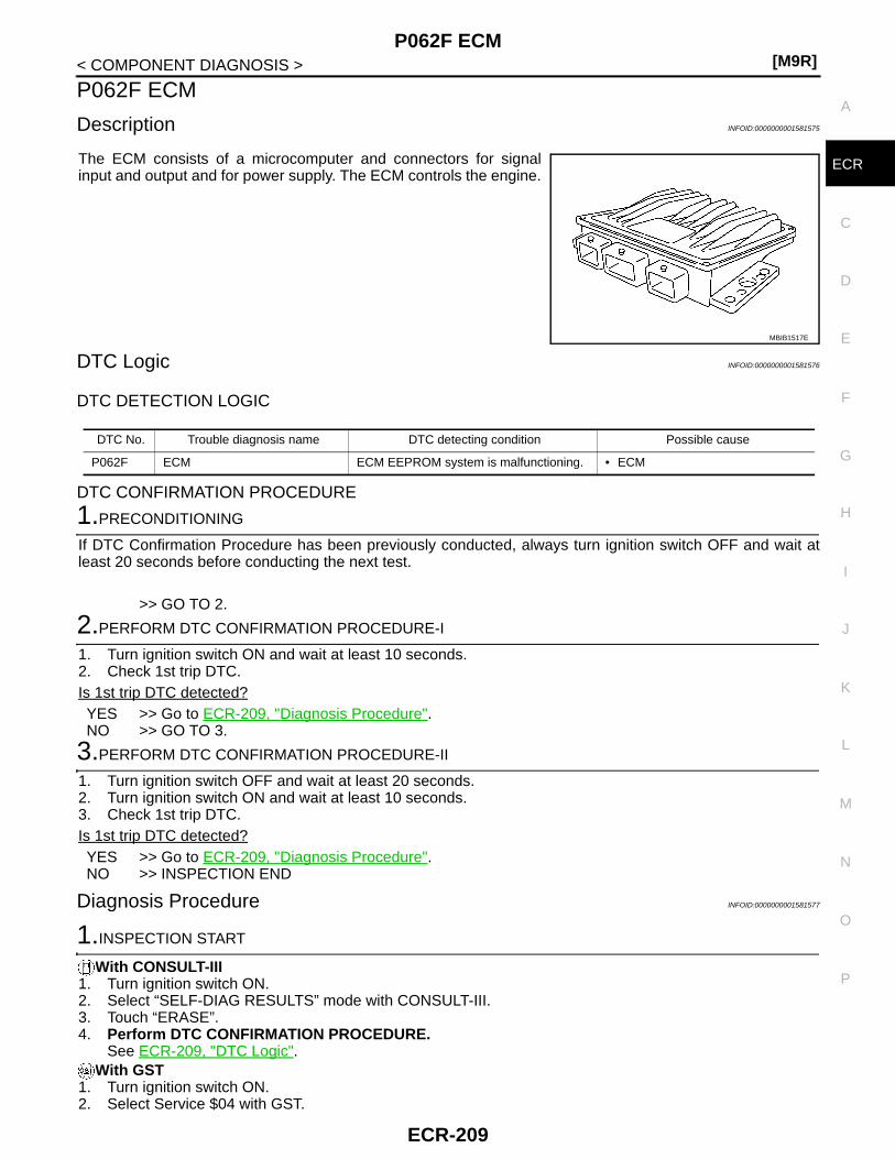
P062F ECM[M9R]
C
D
E
F
G
H
I
J
K
L
M
A
CR
N
P
O
< COMPONENT DIAGNOSIS >
E
P062F ECM
Description INFOID:0000000001581575
The ECM consists of a microcomputer and connectors for signalinput and output and for power supply. The ECM controls the engine.
DTC Logic INFOID:0000000001581576
DTC DETECTION LOGIC
DTC CONFIRMATION PROCEDURE
1.PRECONDITIONING
If DTC Confirmation Procedure has been previously conducted, always turn ignition switch OFF and wait atleast 20 seconds before conducting the next test.
>> GO TO 2.
2.PERFORM DTC CONFIRMATION PROCEDURE-I
1. Turn ignition switch ON and wait at least 10 seconds.2. Check 1st trip DTC.Is 1st trip DTC detected?YES >> Go to ECR-209, "Diagnosis Procedure".NO >> GO TO 3.
3.PERFORM DTC CONFIRMATION PROCEDURE-II
1. Turn ignition switch OFF and wait at least 20 seconds.2. Turn ignition switch ON and wait at least 10 seconds.3. Check 1st trip DTC.Is 1st trip DTC detected?YES >> Go to ECR-209, "Diagnosis Procedure".NO >> INSPECTION END
Diagnosis Procedure INFOID:0000000001581577
1.INSPECTION START
With CONSULT-III1. Turn ignition switch ON.2. Select “SELF-DIAG RESULTS” mode with CONSULT-III.3. Touch “ERASE”.4. Perform DTC CONFIRMATION PROCEDURE.
See ECR-209, "DTC Logic".With GST
1. Turn ignition switch ON.2. Select Service $04 with GST.
MBIB1517E
DTC No. Trouble diagnosis name DTC detecting condition Possible cause
P062F ECM ECM EEPROM system is malfunctioning. • ECM
ECR-209

[M9R]P062F ECM
< COMPONENT DIAGNOSIS >3. Perform DTC CONFIRMATION PROCEDURE.
See ECR-209, "DTC Logic".Is the 1st trip DTC P0606 displayed again?YES >> GO TO 2.NO >> INSPECTION END
2.REPLACE ECM
1. Replace ECM.2. Go to ECR-12, "ADDITIONAL SERVICE WHEN REPLACING CONTROL UNIT : Special Repair Require-
ment".
>> INSPECTION END
ECR-210

P0641 SENSOR POWER SUPPLY[M9R]
C
D
E
F
G
H
I
J
K
L
M
A
CR
N
P
O
< COMPONENT DIAGNOSIS >
E
P0641 SENSOR POWER SUPPLY
DTC Logic INFOID:0000000001581578
DTC DETECTION LOGIC
DTC CONFIRMATION PROCEDURE
1.PRECONDITIONING
If DTC Confirmation Procedure has been previously conducted, always turn ignition switch OFF and wait atleast 20 seconds before conducting the next test.
>> GO TO 2.
2.PERFORM DTC CONFIRMATION PROCEDURE
1. Start engine and let it idle for at least 10 seconds.2. Check 1st trip DTC.Is 1st trip DTC detected?YES >> Go to ECR-211, "Diagnosis Procedure".NO >> INSPECTION END
Diagnosis Procedure INFOID:0000000001581579
1.CHECK GROUND CONNECTION
1. Turn ignition switch OFF and wait at least 20 seconds.2. Check ground connection E17. Refer to Ground Inspection in GI-41, "Circuit Inspection". Is the inspection result normal?YES >> GO TO 2.NO >> Repair or replace ground connection.
2.CHECK ACCELERATOR PEDAL POSITION SENSOR 1 POWER SUPPLY CIRCUIT
1. Disconnect accelerator pedal position (APP) sensor harness connector.2. Turn ignition switch ON.3. Check the voltage between APP sensor harness connector and ground.
Is the inspection result normal?YES >> GO TO 4.NO >> GO TO 3.
3.CHECK SENSOR POWER SUPPLY CIRCUITS
Check harness for short to power and short to ground, between the following terminals.
DTC No. Trouble diagnosis name DTC detecting condition Possible cause
P0641
Sensor power supply circuit low
ECM detects a voltage of power source for sensor is excessively low.
• Harness or connectors(The APP sensor 1 power supply circuit is shorted.)(Turbocharger boost sensor circuit is shorted.)(Exhaust gas pressure sensor circuit is shorted.)
• Accelerator pedal position sensor(APP sensor 1)
• Turbocharger boost sensor• Exhaust gas pressure sensor
Sensor power supply circuit high
ECM detects a voltage of power source for sensor is excessively high.
APP sensorGround Voltage
Connector Terminal
E110 4 Ground Approx. 5V
ECR-211
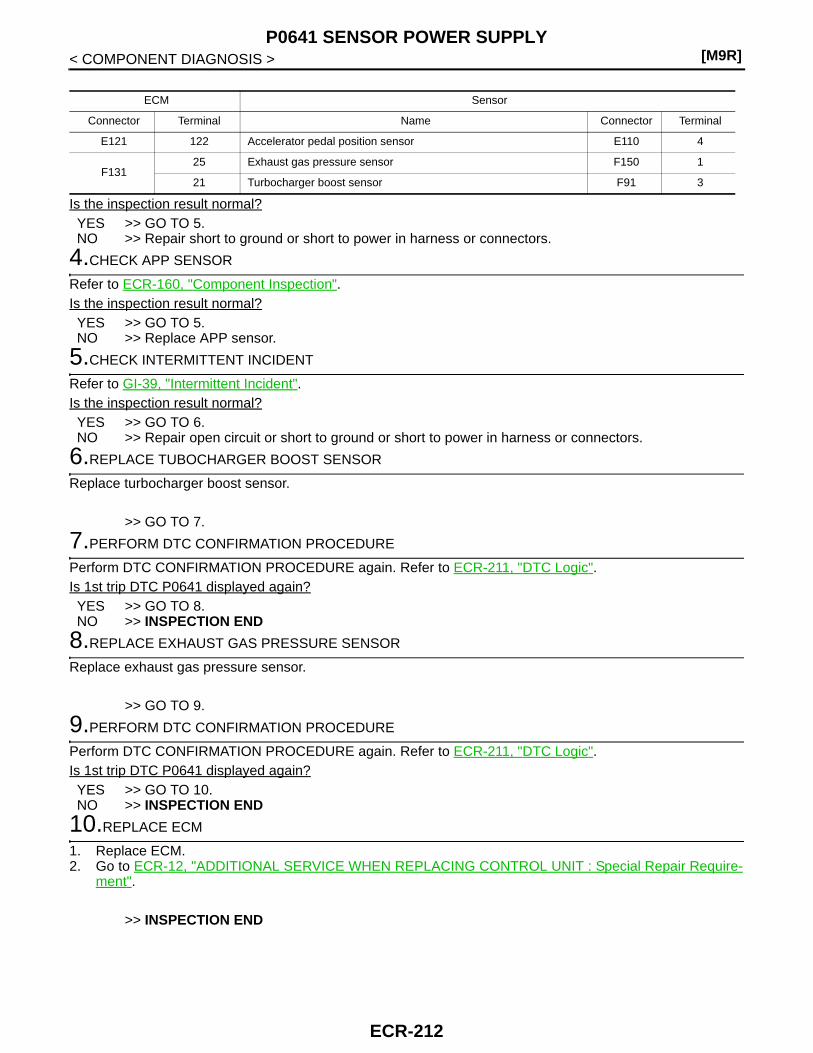
[M9R]P0641 SENSOR POWER SUPPLY
< COMPONENT DIAGNOSIS >
Is the inspection result normal?YES >> GO TO 5.NO >> Repair short to ground or short to power in harness or connectors.
4.CHECK APP SENSOR
Refer to ECR-160, "Component Inspection".Is the inspection result normal?YES >> GO TO 5.NO >> Replace APP sensor.
5.CHECK INTERMITTENT INCIDENT
Refer to GI-39, "Intermittent Incident".Is the inspection result normal?YES >> GO TO 6.NO >> Repair open circuit or short to ground or short to power in harness or connectors.
6.REPLACE TUBOCHARGER BOOST SENSOR
Replace turbocharger boost sensor.
>> GO TO 7.
7.PERFORM DTC CONFIRMATION PROCEDURE
Perform DTC CONFIRMATION PROCEDURE again. Refer to ECR-211, "DTC Logic".Is 1st trip DTC P0641 displayed again?YES >> GO TO 8.NO >> INSPECTION END
8.REPLACE EXHAUST GAS PRESSURE SENSOR
Replace exhaust gas pressure sensor.
>> GO TO 9.
9.PERFORM DTC CONFIRMATION PROCEDURE
Perform DTC CONFIRMATION PROCEDURE again. Refer to ECR-211, "DTC Logic".Is 1st trip DTC P0641 displayed again?YES >> GO TO 10.NO >> INSPECTION END
10.REPLACE ECM
1. Replace ECM.2. Go to ECR-12, "ADDITIONAL SERVICE WHEN REPLACING CONTROL UNIT : Special Repair Require-
ment".
>> INSPECTION END
ECM Sensor
Connector Terminal Name Connector Terminal
E121 122 Accelerator pedal position sensor E110 4
F13125 Exhaust gas pressure sensor F150 1
21 Turbocharger boost sensor F91 3
ECR-212

P0651 SENSOR POWER SUPPLY[M9R]
C
D
E
F
G
H
I
J
K
L
M
A
CR
N
P
O
< COMPONENT DIAGNOSIS >
E
P0651 SENSOR POWER SUPPLY
DTC Logic INFOID:0000000001581580
DTC DETECTION LOGIC
DTC CONFIRMATION PROCEDURE
1.PRECONDITIONING
If DTC Confirmation Procedure has been previously conducted, always turn ignition switch OFF and wait atleast 20 seconds before conducting the next test.
>> GO TO 2.
2.PERFORM DTC CONFIRMATION PROCEDURE
1. Start engine and let it idle for at least 10 seconds.2. Check 1st trip DTC.Is 1st trip DTC detected?YES >> Go to ECR-213, "Diagnosis Procedure".NO >> INSPECTION END
Diagnosis Procedure INFOID:0000000001581581
1.CHECK GROUND CONNECTION
1. Turn ignition switch OFF and wait at least 20 seconds.2. Check ground connection E17. Refer to Ground Inspection in GI-41, "Circuit Inspection". Is the inspection result normal?YES >> GO TO 2.NO >> Repair or replace ground connection.
2.CHECK ACCELERATOR PEDAL POSITION SENSOR 2 POWER SUPPLY CIRCUIT
1. Disconnect accelerator pedal position (APP) sensor harness connector.2. Turn ignition switch ON.3. Check the voltage between APP sensor harness connector and ground.
Is the inspection result normal?YES >> GO TO 4.NO >> GO TO 3.
DTC No. Trouble diagnosis name DTC detecting condition Possible cause
P0651
Sensor power supply circuit low
ECM detects a voltage of power source for sensor is excessively low.
• Harness or connectors(The APP sensor 2 power supply circuit is shorted.)(Differential exhaust pressure sensor circuit is shorted.)(EGR volume control valve control position sensor circuit is shorted.)(Throttle position sensor circuit is shorted.)(Refrigerant pressure sensor circuit is shorted.)
• Accelerator pedal position sensor(APP sensor 2)
• Exhaust differential pressure sensor• EGR volume control valve control position sensor• Throttle position sensor• Refrigerant pressure sensor
Sensor power supply circuit high
ECM detects a voltage of power source for sensor is excessively high.
APP sensorGround Voltage
Connector Terminal
E110 5 Ground Approx. 5V
ECR-213

[M9R]P0651 SENSOR POWER SUPPLY
< COMPONENT DIAGNOSIS >
3.CHECK SENSOR POWER SUPPLY CIRCUITS
Check harness for short to power and short to ground between the following terminals.
Is the inspection result normal?YES >> GO TO 5.NO >> Repair short to ground or short to power in harness or connectors.
4.CHECK COMPONENTS
Check the following.• Throttle position sensor (Refer to ECR-134, "Diagnosis Procedure".)• EGR volume control valve (EGR volume control valve control position sensor) (Refer to ECR-175, "Diagno-
sis Procedure".)Is the inspection result normal?YES >> GO TO 5.NO >> Replace malfunctioning component.
5.CHECK APP SENSOR
Refer to ECR-160, "Component Inspection".Is the inspection result normal?YES >> GO TO 6.NO >> Replace APP sensor.
6.CHECK INTERMITTENT INCIDENT
Refer to GI-39, "Intermittent Incident".Is the inspection result normal?YES >> GO TO 7.NO >> Repair open circuit or short to ground or short to power in harness or connectors.
7.REPLACE DIFFERENTIAL EXHAUST PRESSURE SENSOR
Replace differential exhaust pressure sensor.
>> GO TO 8.
8.PERFORM DTC CONFIRMATION PROCEDURE
Perform DTC CONFIRMATION PROCEDURE again. Refer to ECR-213, "DTC Logic".Is 1st trip DTC P0651 displayed again?YES >> GO TO 9.NO >> INSPECTION END
9.REPLACE REFRIGERANT PRESSURE SENSOR
Replace refrigerant pressure sensor.
>> GO TO 10.
10.PERFORM DTC CONFIRMATION PROCEDURE
Perform DTC CONFIRMATION PROCEDURE again. Refer to ECR-213, "DTC Logic".
ECM Sensor
Connector Terminal Name Connector Terminal
E121 118 APP sensor E110 5
F132 75 Throttle position sensor F148 3
F131
37 Exhaust differential pressure sensor F135 3
33EGR volume control valve (EGR volume control valve control posi-tion sensor)
F99 4
41 Refrigerant pressure sensor E50 3
ECR-214

P0651 SENSOR POWER SUPPLY[M9R]
C
D
E
F
G
H
I
J
K
L
M
A
CR
N
P
O
< COMPONENT DIAGNOSIS >
E
Is 1st trip DTC P0651 displayed again?YES >> GO TO 11.NO >> INSPECTION END
11.REPLACE ECM
1. Replace ECM.2. Go to ECR-12, "ADDITIONAL SERVICE WHEN REPLACING CONTROL UNIT : Special Repair Require-
ment".
>> INSPECTION END
ECR-215

[M9R]P0670 GLOW CONTROL SYSTEM
< COMPONENT DIAGNOSIS >
P0670 GLOW CONTROL SYSTEM
DTC Logic INFOID:0000000001581582
DTC DETECTION LOGIC
DTC CONFIRMATION PROCEDURE
1.PRECONDITIONING
If DTC Confirmation Procedure has been previously conducted, always turn ignition switch OFF and wait atleast 20 seconds before conducting the next test.
>> GO TO 2.
2.PERFORM DTC CONFIRMATION PROCEDURE-I
1. Turn ignition switch ON and wait at least 10 seconds.2. Check 1st trip DTC.Is 1st trip DTC detected?YES >> Go to ECR-216, "Diagnosis Procedure".NO >> GO TO 3.
3.PERFORM DTC CONFIRMATION PROCEDURE
With CONSULT-III1. Select “DATA MONITOR” mode with CONSULT-III.2. Check the “ENG COOLAN TEMP” indication.
If indication is below 50 °C (122 °F), go to the next step.If indication is above 50 °C (122 °F), cool down engine and then go to the next step.
3. Wait at least 10 seconds.4. Check 1st trip DTC.
With GSTFollow the procedure “With CONSULT-III” above.Is 1st trip DTC detected?YES >> Go to ECR-216, "Diagnosis Procedure".NO >> INSPECTION END
Diagnosis Procedure INFOID:0000000001581583
1.CHECK GLOW CONTROL UNIT POWER SUPPLY CIRCUIT
1. Turn ignition switch OFF and wait at least 20 seconds.2. Disconnect glow control unit harness connector.3. Turn ignition switch ON.4. Check the voltage between glow control unit harness connector and ground.
Is the inspection result normal?YES >> GO TO 3.NO >> GO TO 2.
DTC No. Trouble diagnosis name DTC detecting condition Possible cause
P0670 Glow control unit circuit
ECM detects short circuit in output signal circuit. • Harness or connectors
(Glow control unit circuit is open or shorted.)• Glow control unitECM detects open circuit in output signal
circuit.
Glow control unitGround Voltage
Connector Terminal
F94 4 Ground Battery voltage
ECR-216
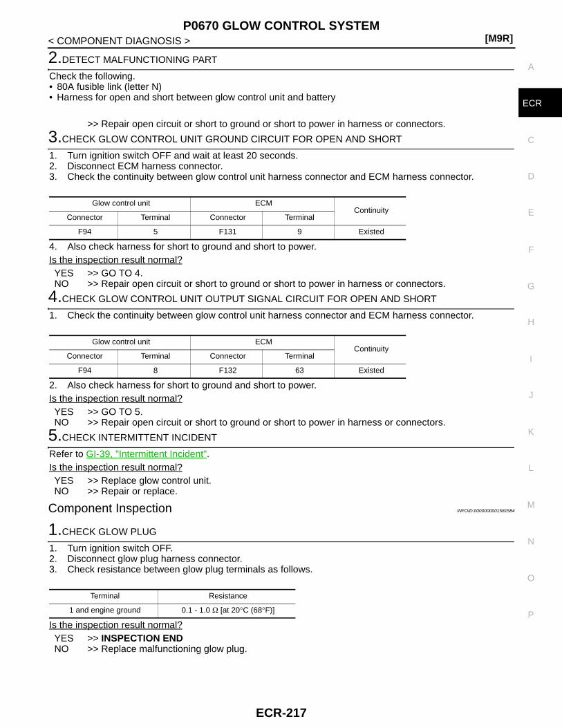
P0670 GLOW CONTROL SYSTEM[M9R]
C
D
E
F
G
H
I
J
K
L
M
A
CR
N
P
O
< COMPONENT DIAGNOSIS >
E
2.DETECT MALFUNCTIONING PART
Check the following.• 80A fusible link (letter N)• Harness for open and short between glow control unit and battery
>> Repair open circuit or short to ground or short to power in harness or connectors.
3.CHECK GLOW CONTROL UNIT GROUND CIRCUIT FOR OPEN AND SHORT
1. Turn ignition switch OFF and wait at least 20 seconds.2. Disconnect ECM harness connector.3. Check the continuity between glow control unit harness connector and ECM harness connector.
4. Also check harness for short to ground and short to power. Is the inspection result normal?YES >> GO TO 4.NO >> Repair open circuit or short to ground or short to power in harness or connectors.
4.CHECK GLOW CONTROL UNIT OUTPUT SIGNAL CIRCUIT FOR OPEN AND SHORT
1. Check the continuity between glow control unit harness connector and ECM harness connector.
2. Also check harness for short to ground and short to power. Is the inspection result normal?YES >> GO TO 5.NO >> Repair open circuit or short to ground or short to power in harness or connectors.
5.CHECK INTERMITTENT INCIDENT
Refer to GI-39, "Intermittent Incident".Is the inspection result normal?YES >> Replace glow control unit.NO >> Repair or replace.
Component Inspection INFOID:0000000001581584
1.CHECK GLOW PLUG
1. Turn ignition switch OFF.2. Disconnect glow plug harness connector.3. Check resistance between glow plug terminals as follows.
Is the inspection result normal?YES >> INSPECTION ENDNO >> Replace malfunctioning glow plug.
Glow control unit ECMContinuity
Connector Terminal Connector Terminal
F94 5 F131 9 Existed
Glow control unit ECMContinuity
Connector Terminal Connector Terminal
F94 8 F132 63 Existed
Terminal Resistance
1 and engine ground 0.1 - 1.0 Ω [at 20°C (68°F)]
ECR-217
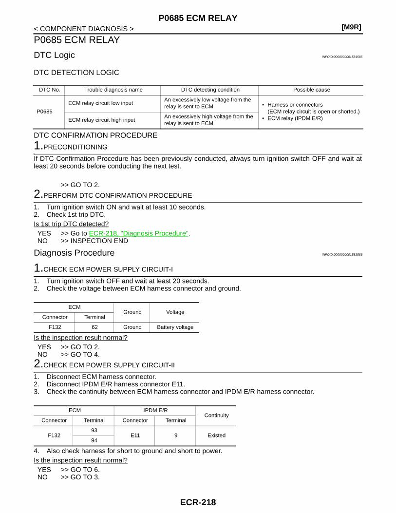
[M9R]P0685 ECM RELAY
< COMPONENT DIAGNOSIS >
P0685 ECM RELAY
DTC Logic INFOID:0000000001581585
DTC DETECTION LOGIC
DTC CONFIRMATION PROCEDURE
1.PRECONDITIONING
If DTC Confirmation Procedure has been previously conducted, always turn ignition switch OFF and wait atleast 20 seconds before conducting the next test.
>> GO TO 2.
2.PERFORM DTC CONFIRMATION PROCEDURE
1. Turn ignition switch ON and wait at least 10 seconds.2. Check 1st trip DTC.Is 1st trip DTC detected?YES >> Go to ECR-218, "Diagnosis Procedure".NO >> INSPECTION END
Diagnosis Procedure INFOID:0000000001581586
1.CHECK ECM POWER SUPPLY CIRCUIT-I
1. Turn ignition switch OFF and wait at least 20 seconds.2. Check the voltage between ECM harness connector and ground.
Is the inspection result normal?YES >> GO TO 2.NO >> GO TO 4.
2.CHECK ECM POWER SUPPLY CIRCUIT-II
1. Disconnect ECM harness connector.2. Disconnect IPDM E/R harness connector E11.3. Check the continuity between ECM harness connector and IPDM E/R harness connector.
4. Also check harness for short to ground and short to power.Is the inspection result normal?YES >> GO TO 6.NO >> GO TO 3.
DTC No. Trouble diagnosis name DTC detecting condition Possible cause
P0685
ECM relay circuit low inputAn excessively low voltage from the relay is sent to ECM. • Harness or connectors
(ECM relay circuit is open or shorted.)• ECM relay (IPDM E/R)ECM relay circuit high input
An excessively high voltage from the relay is sent to ECM.
ECMGround Voltage
Connector Terminal
F132 62 Ground Battery voltage
ECM IPDM E/RContinuity
Connector Terminal Connector Terminal
F13293
E11 9 Existed94
ECR-218

P0685 ECM RELAY[M9R]
C
D
E
F
G
H
I
J
K
L
M
A
CR
N
P
O
< COMPONENT DIAGNOSIS >
E
3.DETECT MALFUNCTIONING PART
Check the following.• Harness or connectors E7, F121• Harness for open or short between ECM and IPDM E/R
>> Repair open circuit or short to ground or short to power in harness or connectors.
4.CHECK ECM POWER SUPPLY CIRCUIT-III
1. Disconnect ECM harness connector.2. Disconnect IPDM E/R harness connector E11.3. Check the continuity between ECM harness connector and IPDM E/R harness connector.
4. Also check harness for short to ground and short to power.Is the inspection result normal?YES >> GO TO 5NO >> Repair open circuit or short to ground or short power in harness or connectors.
5.CHECK 20A FUSE
1. Disconnect 20A fuse (No. 52) from IPDM E/R.2. Check 20A fuse.Is the inspection result normal?YES >> GO TO 6.NO >> Replace 20A fuse.
6.CHECK GROUND CONNECTION
Check ground connection E17. Refer to Ground Inspection in GI-41, "Circuit Inspection".Is the inspection result normal?YES >> GO TO 7.NO >> Repair or replace ground connection.
7.CHECK ECM GROUND CIRCUIT FOR OPEN AND SHORT
1. Check the continuity between ECM harness connector and ground.
2. Also check harness for short to power.Is the inspection result normal?YES >> GO TO 8.NO >> Repair open circuit or short power in harness or connectors.
8.CHECK INTERMITTENT INCIDENT
Refer to GI-39, "Intermittent Incident".Is the inspection result normal?YES >> Replace IPDM E/R.NO >> Repair or replace.
ECM IPDM E/RContinuity
Connector Terminal Connector Terminal
F132 62 E11 15 Existed
ECMGround Continuity
Connector Terminal
E121
123
Ground Existed124
125
128
ECR-219
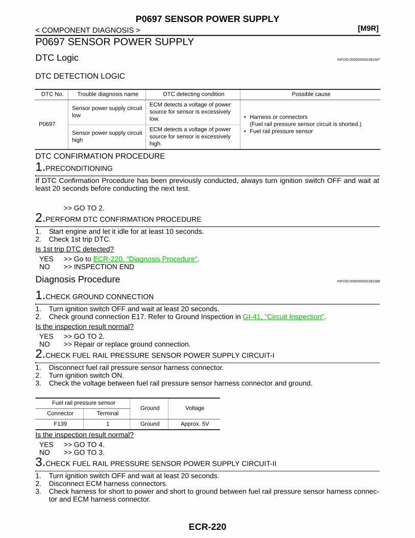
[M9R]P0697 SENSOR POWER SUPPLY
< COMPONENT DIAGNOSIS >
P0697 SENSOR POWER SUPPLY
DTC Logic INFOID:0000000001581587
DTC DETECTION LOGIC
DTC CONFIRMATION PROCEDURE
1.PRECONDITIONING
If DTC Confirmation Procedure has been previously conducted, always turn ignition switch OFF and wait atleast 20 seconds before conducting the next test.
>> GO TO 2.
2.PERFORM DTC CONFIRMATION PROCEDURE
1. Start engine and let it idle for at least 10 seconds.2. Check 1st trip DTC.Is 1st trip DTC detected?YES >> Go to ECR-220, "Diagnosis Procedure".NO >> INSPECTION END
Diagnosis Procedure INFOID:0000000001581588
1.CHECK GROUND CONNECTION
1. Turn ignition switch OFF and wait at least 20 seconds.2. Check ground connection E17. Refer to Ground Inspection in GI-41, "Circuit Inspection". Is the inspection result normal?YES >> GO TO 2.NO >> Repair or replace ground connection.
2.CHECK FUEL RAIL PRESSURE SENSOR POWER SUPPLY CIRCUIT-I
1. Disconnect fuel rail pressure sensor harness connector.2. Turn ignition switch ON.3. Check the voltage between fuel rail pressure sensor harness connector and ground.
Is the inspection result normal?YES >> GO TO 4.NO >> GO TO 3.
3.CHECK FUEL RAIL PRESSURE SENSOR POWER SUPPLY CIRCUIT-II
1. Turn ignition switch OFF and wait at least 20 seconds.2. Disconnect ECM harness connectors.3. Check harness for short to power and short to ground between fuel rail pressure sensor harness connec-
tor and ECM harness connector.
DTC No. Trouble diagnosis name DTC detecting condition Possible cause
P0697
Sensor power supply circuit low
ECM detects a voltage of power source for sensor is excessively low. • Harness or connectors
(Fuel rail pressure sensor circuit is shorted.)• Fuel rail pressure sensorSensor power supply circuit
high
ECM detects a voltage of power source for sensor is excessively high.
Fuel rail pressure sensorGround Voltage
Connector Terminal
F139 1 Ground Approx. 5V
ECR-220

P0697 SENSOR POWER SUPPLY[M9R]
C
D
E
F
G
H
I
J
K
L
M
A
CR
N
P
O
< COMPONENT DIAGNOSIS >
EIs the inspection result normal?YES >> GO TO 4.NO >> Repair short to ground or short to power in harness or connectors.
4.CHECK FUEL RAIL PRESSURE SENSOR
Refer to ECR-151, "Component Inspection".Is the inspection result normal?YES >> GO TO 5.NO >> Replace fuel rail pressure sensor.
5.CHECK INTERMITTENT INCIDENT
Refer to GI-39, "Intermittent Incident".
>> INSPECTION END
ECM Sensor
Connector Terminal Name Connector Terminal
F131 29 Fuel rail pressure sensor F139 1
ECR-221

[M9R]P1201, P1202, P1203, P1204 FUEL INJECTOR
< COMPONENT DIAGNOSIS >
P1201, P1202, P1203, P1204 FUEL INJECTOR
Description INFOID:0000000001581589
The fuel injector is a small, precise solenoid valve. When the ECM supplies a ground to the fuel injector circuit,the coil in the fuel injector is energized. The energized coil pulls the needle valve back and allows fuel to flowthrough the fuel injector into the cylinder. The amount of fuel injected depends upon the injection pulse dura-tion. Pulse duration is the length of time the fuel injector remains open. The ECM controls the injection pulseduration based on engine fuel needs.
DTC Logic INFOID:0000000001581590
DTC DETECTION LOGIC
DTC CONFIRMATION PROCEDURE
1.PRECONDITIONING
If DTC Confirmation Procedure has been previously conducted, always turn ignition switch OFF and wait atleast 20 seconds before conducting the next test.
>> GO TO 2.
2.PERFORM DTC CONFIRMATION PROCEDURE
1. Start engine and let it idle for at least 1 minutes.2. Check 1st trip DTC.Is 1st trip DTC detected?YES >> Go to ECR-222, "Diagnosis Procedure".NO >> INSPECTION END
Diagnosis Procedure INFOID:0000000001581591
1.CHECK FUEL INJECTOR POWER SUPPLY CIRCUIT FOR OPEN AND SHORT
1. Turn ignition switch OFF and wait at least 20 seconds.2. Disconnect ECM harness connector.3. Disconnect fuel injector harness connector.4. Check the continuity between fuel injector harness connector and ECM harness connector.
5. Also check harness for short to ground and short to power. Is the inspection result normal?YES >> GO TO 2.NO >> Repair open circuit or short to ground or short to power in harness or connectors.
2.CHECK FUEL INJECTOR OUTPUT SIGNAL CIRCUIT FOR OPEN AND SHORT
DTC No. Trouble diagnosis name DTC detecting condition Possible cause
P1201 Fuel injector No. 1 performance Fuel injector No. 1 does not operate properly.• Harness or connectors
(The fuel injector circuit is open or shorted.)
• Fuel injector
P1202 Fuel injector No. 2 performance Fuel injector No. 2 does not operate properly.
P1203 Fuel injector No. 3 performance Fuel injector No. 3 does not operate properly.
P1204 Fuel injector No. 4 performance Fuel injector No. 4 does not operate properly.
Fuel injector ECMContinuity
Cylinder Connector Terminal Connector Terminal
1 F144 1
F131
6
Existed2 F145 1 7
3 F146 1 8
4 F147 1 5
ECR-222
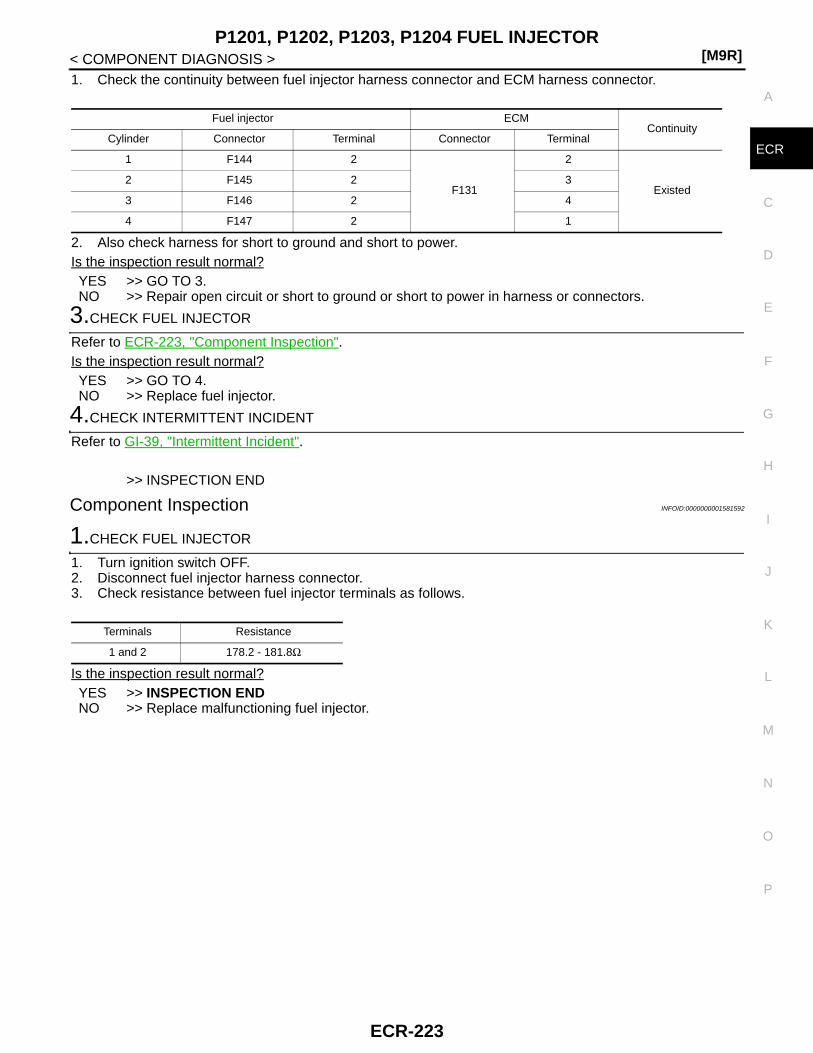
P1201, P1202, P1203, P1204 FUEL INJECTOR[M9R]
C
D
E
F
G
H
I
J
K
L
M
A
CR
N
P
O
< COMPONENT DIAGNOSIS >
E
1. Check the continuity between fuel injector harness connector and ECM harness connector.
2. Also check harness for short to ground and short to power. Is the inspection result normal?YES >> GO TO 3.NO >> Repair open circuit or short to ground or short to power in harness or connectors.
3.CHECK FUEL INJECTOR
Refer to ECR-223, "Component Inspection".Is the inspection result normal?YES >> GO TO 4.NO >> Replace fuel injector.
4.CHECK INTERMITTENT INCIDENT
Refer to GI-39, "Intermittent Incident".
>> INSPECTION END
Component Inspection INFOID:0000000001581592
1.CHECK FUEL INJECTOR
1. Turn ignition switch OFF.2. Disconnect fuel injector harness connector.3. Check resistance between fuel injector terminals as follows.
Is the inspection result normal?YES >> INSPECTION ENDNO >> Replace malfunctioning fuel injector.
Fuel injector ECMContinuity
Cylinder Connector Terminal Connector Terminal
1 F144 2
F131
2
Existed2 F145 2 3
3 F146 2 4
4 F147 2 1
Terminals Resistance
1 and 2 178.2 - 181.8Ω
ECR-223

[M9R]P1435 DPF REGENERATION
< COMPONENT DIAGNOSIS >
P1435 DPF REGENERATION
Description INFOID:0000000001581593
DPF (Diesel Particulate Filter) is placed after oxidation catalyst and traps PM (Particulate Matter) in exhaustgas. DPF is formed in a honeycomb form made of ceramic. This structure facilitates to trap particulate matter.When the amount of particulate matter in the DPF reaches the specified level, the particulate matter needs tobe reduced through burning to maintain the DPF function. This reducing of particulate matter is called Regen-eration and should be performed periodically. DPF can be effective for a long time through the cycle of trap-ping particulate matter and regeneration.
DTC Logic INFOID:0000000001581594
DTC DETECTION LOGIC
DTC CONFIRMATION PROCEDURE
1.PRECONDITIONING
If DTC Confirmation Procedure has been previously conducted, always turn ignition switch OFF and wait atleast 20 seconds before conducting the next test.
>> GO TO 2.
2.PERFORM DTC CONFIRMATION PROCEDURE
1. Start engine.2. Check 1st trip DTC.Is 1st trip DTC detected?YES >> Go to ECR-225, "Diagnosis Procedure".
PBIB3160E
DTC No. Trouble diagnosis name DTC detecting condition Possible cause
P1435Diesel particulate filter (DPF) regeneration performance
DPF regeneration failed many times. DPF
ECR-224

P1435 DPF REGENERATION[M9R]
C
D
E
F
G
H
I
J
K
L
M
A
CR
N
P
O
< COMPONENT DIAGNOSIS >
E
NO >> INSPECTION END
Diagnosis Procedure INFOID:0000000001581595
1.CHECK DPF
Refer to ECR-232, "Component Inspection".OK or NGOK >> INSPECTION ENDNG >> GO TO 2.
2.REPLACE DPF
1. Replace DPF.2. Perform “DPF Data Clear”. Refer to ECR-17, "DPF DATA CLEAR : Special Repair Requirement".
>> INSPECTION END
Component Inspection INFOID:0000000001581596
1.CHECK DPF-I
Check DPF for damage.Is the inspection result normal?YES >> GO TO 2.NO >> GO TO 3.
2.CHECK DPF-II
1. Perform “Service Regeneration”. Refer to ECR-17, "SERVICE REGENERATION : Special RepairRequirement".
2. Start engine and warm it up to normal operating temperature.3. Connect CONSULT-III and select “DATA MONITOR” mode.4. Select “DIFF EXH PRES” and check the indication under the following conditions.
Is the inspection result normal?YES >> INSPECTION ENDNO >> GO TO 3.
3.REPLACE DPF
1. Replace DPF.2. Perform “DPF Data Clear”. Refer to ECR-17, "DPF DATA CLEAR : Special Repair Requirement".
>> INSPECTION END
Condition DIFF EXH PRES [mbar]
• ENGINE SPEED·: 2000 tr/min• EXH GAS TEMP2: 150 - 200°C (302 - 392°F)• EXH GAS TEMP3: 150 - 200°C (302 - 392°F)
Less than 3.0
ECR-225

[M9R]P1436 DPF REGENERATION
< COMPONENT DIAGNOSIS >
P1436 DPF REGENERATION
Description INFOID:0000000001581597
DPF (Diesel Particulate Filter) is placed after oxidation catalyst and traps PM (Particulate Matter) in exhaustgas. DPF is formed in a honeycomb form made of ceramic. This structure facilitates to trap particulate matter.When the amount of particulate matter in the DPF reaches the specified level, the particulate matter needs tobe reduced through burning to maintain the DPF function. This reducing of particulate matter is called Regen-eration and should be performed periodically. DPF can be effective for a long time through the cycle of trap-ping particulate matter and regeneration.
DTC Logic INFOID:0000000001581598
DTC DETECTION LOGIC
DTC CONFIRMATION PROCEDURE
1.PRECONDITIONING
If DTC Confirmation Procedure has been previously conducted, always turn ignition switch OFF and wait atleast 20 seconds before conducting the next test.
>> GO TO 2.
2.PERFORM DTC CONFIRMATION PROCEDURE
1. Start engine.2. Check 1st trip DTC.Is 1st trip DTC detected?YES >> Go to ECR-227, "Diagnosis Procedure".
PBIB3160E
DTC No. Trouble diagnosis name DTC detecting condition Possible cause
P1436Diesel particulate filter (DPF) regeneration performance
DPF regeneration is not completed successfully. DPF
ECR-226
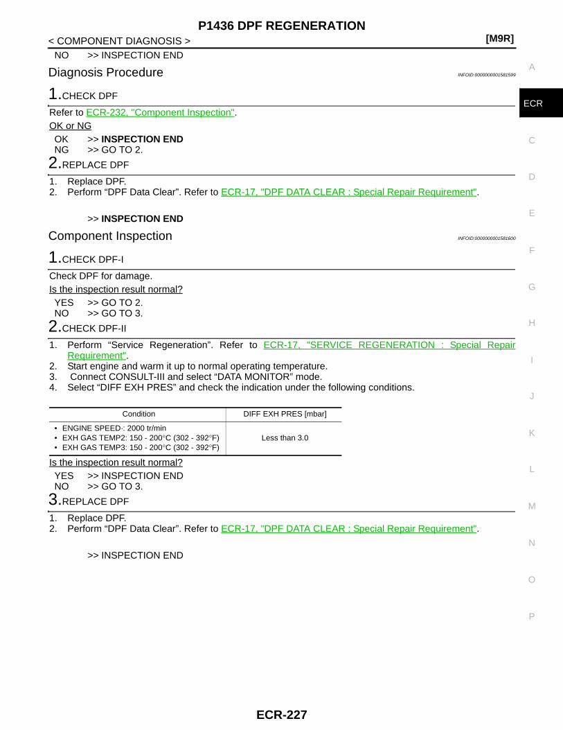
P1436 DPF REGENERATION[M9R]
C
D
E
F
G
H
I
J
K
L
M
A
CR
N
P
O
< COMPONENT DIAGNOSIS >
E
NO >> INSPECTION END
Diagnosis Procedure INFOID:0000000001581599
1.CHECK DPF
Refer to ECR-232, "Component Inspection".OK or NGOK >> INSPECTION ENDNG >> GO TO 2.
2.REPLACE DPF
1. Replace DPF.2. Perform “DPF Data Clear”. Refer to ECR-17, "DPF DATA CLEAR : Special Repair Requirement".
>> INSPECTION END
Component Inspection INFOID:0000000001581600
1.CHECK DPF-I
Check DPF for damage.Is the inspection result normal?YES >> GO TO 2.NO >> GO TO 3.
2.CHECK DPF-II
1. Perform “Service Regeneration”. Refer to ECR-17, "SERVICE REGENERATION : Special RepairRequirement".
2. Start engine and warm it up to normal operating temperature.3. Connect CONSULT-III and select “DATA MONITOR” mode.4. Select “DIFF EXH PRES” and check the indication under the following conditions.
Is the inspection result normal?YES >> INSPECTION ENDNO >> GO TO 3.
3.REPLACE DPF
1. Replace DPF.2. Perform “DPF Data Clear”. Refer to ECR-17, "DPF DATA CLEAR : Special Repair Requirement".
>> INSPECTION END
Condition DIFF EXH PRES [mbar]
• ENGINE SPEED·: 2000 tr/min• EXH GAS TEMP2: 150 - 200°C (302 - 392°F)• EXH GAS TEMP3: 150 - 200°C (302 - 392°F)
Less than 3.0
ECR-227

[M9R]P1607 ECM
< COMPONENT DIAGNOSIS >
P1607 ECM
Description INFOID:0000000001581601
The ECM consists of a microcomputer and connectors for signalinput and output and for power supply. The ECM controls the engine.
DTC Logic INFOID:0000000001581602
DTC DETECTION LOGIC
Diagnosis Procedure INFOID:0000000001581603
1.INSPECTION START
With CONSULT-III1. Turn ignition switch ON.2. Select “SELF-DIAG RESULTS” mode with CONSULT-III.3. Touch “ERASE”.4. Perform DTC CONFIRMATION PROCEDURE.
See ECR-228, "DTC Logic".With GST
1. Turn ignition switch ON.2. Select Service $04 with GST.3. Perform DTC CONFIRMATION PROCEDURE.
See ECR-228, "DTC Logic".Is the 1st trip DTC P0606 displayed again?YES >> GO TO 2.NO >> INSPECTION END
2.REPLACE ECM
1. Replace ECM.2. Go to ECR-12, "ADDITIONAL SERVICE WHEN REPLACING CONTROL UNIT : Special Repair Require-
ment".
>> INSPECTION END
MBIB1517E
DTC No. Trouble diagnosis name DTC detecting condition Possible cause
P1607 Engine control module ECM function is malfunctioning. • ECM
ECR-228

P2002 DPF[M9R]
C
D
E
F
G
H
I
J
K
L
M
A
CR
N
P
O
< COMPONENT DIAGNOSIS >
E
P2002 DPF
Description INFOID:0000000001581604
DPF (Diesel Particulate Filter) is placed after oxidation catalyst and traps PM (Particulate Matter) in exhaustgas. DPF is formed in a honeycomb form made of ceramic. This structure facilitates to trap particulate matter.When the amount of particulate matter in the DPF reaches the specified level, the particulate matter needs tobe reduced through burning to maintain the DPF function. This reducing of particulate matter is called Regen-eration and should be performed periodically. DPF can be effective for a long time through the cycle of trap-ping particulate matter and regeneration.
DTC Logic INFOID:0000000001581605
DTC DETECTION LOGIC
DTC CONFIRMATION PROCEDURE
1.PRECONDITIONING
If DTC Confirmation Procedure has been previously conducted, always turn ignition switch OFF and wait atleast 20 seconds before conducting the next test.
>> GO TO 2.
2.PERFORM DTC CONFIRMATION PROCEDURE
1. Start engine and let it idle for at least 5 minutes.2. Drive vehicle under the following conditions for at least 2 minutes.- Gear position: 3rd position
PBIB3160E
DTC No. Trouble diagnosis name DTC detecting condition Possible cause
P2002Diesel particulate filter (DPF) efficiency below threshold
• Differential exhaust pressure exceeds a standard level for more than 10 seconds.
• Exhaust gas temperature does not raise during DPF regeneration.
• DPF• Exhaust gas temperature sensor 2• Exhaust gas temperature sensor 3
ECR-229

[M9R]P2002 DPF
< COMPONENT DIAGNOSIS >- Engine speed: About 3,000 rpm3. Check 1st trip DTC.Is 1st trip DTC detected?YES >> Go to ECR-187, "Diagnosis Procedure".NO >> INSPECTION END
Diagnosis Procedure INFOID:0000000001581606
1.CHECK EXHAUST GAS TEMPERATURE SENSOR 2
Refer to ECR-232, "Component Inspection".OK or NGOK >> GO TO 2.NG >> Replace exhaust gas temperature sensor 2.
2.CHECK EXHAUST GAS TEMPERATURE SENSOR 3
Refer to ECR-265, "Component Inspection".OK or NGOK >> GO TO 3.NG >> Replace exhaust gas temperature sensor 3.
3.CHECK DPF
Refer to ECR-230, "Component Inspection".OK or NGOK >> INSPECTION ENDNG >> Replace DPF.
Component Inspection INFOID:0000000001581607
1.CHECK DPF-I
Check DPF for damage.Is the inspection result normal?YES >> GO TO 2.NO >> GO TO 3.
2.CHECK DPF-II
1. Perform “Service Regeneration”. Refer to ECR-17, "SERVICE REGENERATION : Special RepairRequirement".
2. Start engine and warm it up to normal operating temperature.3. Connect CONSULT-III and select “DATA MONITOR” mode.4. Select “DIFF EXH PRES” and check the indication under the following conditions.
Is the inspection result normal?YES >> INSPECTION ENDNO >> GO TO 3.
3.REPLACE DPF
1. Replace DPF.2. Perform “DPF Data Clear”. Refer to ECR-17, "DPF DATA CLEAR : Special Repair Requirement".
>> INSPECTION END
Condition DIFF EXH PRES [mbar]
• ENGINE SPEED·: 2000 tr/min• EXH GAS TEMP2: 150 - 200°C (302 - 392°F)• EXH GAS TEMP3: 150 - 200°C (302 - 392°F)
Less than 3.0
ECR-230

P2031 EGT SENSOR 2[M9R]
C
D
E
F
G
H
I
J
K
L
M
A
CR
N
P
O
< COMPONENT DIAGNOSIS >
E
P2031 EGT SENSOR 2
Description INFOID:0000000001581608
Exhaust gas temperature sensor 2 is installed before DPF and senses exhaust gas temperature. Exhaust gastemperature sensor 2 uses a thermistor which is sensitive to the change in temperature. Electrical resistanceof the thermistor decreases in response to the temperature rise.
<Reference data>
DTC Logic INFOID:0000000001581609
DTC DETECTION LOGICIf DTC P2031 is displayed with DTC P0115, first perform the trouble diagnosis for DTC P0115. Refer toECR-132, "DTC Logic".
DTC CONFIRMATION PROCEDURE
1.PRECONDITIONING
If DTC Confirmation Procedure has been previously conducted, always turn ignition switch OFF and wait atleast 20 seconds before conducting the next test.
>> GO TO 2.
2.PERFORM DTC CONFIRMATION PROCEDURE-I
1. Turn ignition switch ON and wait at least 10 seconds.2. Check 1st trip DTC.Is 1st trip DTC detected?YES >> Go to ECR-232, "Diagnosis Procedure".NO >> GO TO 3.
3.PERFORM DTC CONFIRMATION PROCEDURE-II
1. Start engine and drive vehicle under the following conditions for at least 10 seconds.- Gear position: 3rd position- Vehicle speed: Accelerates from 55km/h (34 MPH) to 70 km/h (43 MPH)2. Check 1st trip DTC.Is 1st trip DTC detected?YES >> Go to ECR-232, "Diagnosis Procedure".NO >> INSPECTION END
Exhaust gas temperature °C (°F) Resistance kΩ
50 (122) 106.18
100 (212) 33.56
350 (662) 1.587 - 1.848
500 (932) 0.640 - 0.709
700 (1292) 0.277 - 0.297
900 (1652) 0.155
DTC No. Trouble diagnosis name DTC detecting condition Possible cause
P2031
Exhaust gas temperature sensor 2 circuit low input
An excessively low voltage from the sensor is sent to ECM.
• Harness or connectors(Exhaust gas temperature sensor 2 circuit is open or shorted.)
• Exhaust gas temperature sensor 2Exhaust gas temperature sensor 2 circuit high input
An excessively high voltage from the sensor is sent to ECM.
ECR-231

[M9R]P2031 EGT SENSOR 2
< COMPONENT DIAGNOSIS >
Diagnosis Procedure INFOID:0000000001581610
1.CHECK GROUND CONNECTIONS
1. Turn ignition switch OFF and wait at least 20 seconds.2. Check ground connection E17. Refer to Ground inspection in GI-41, "Circuit Inspection".Is the inspection result normal?YES >> GO TO 2.NO >> Repair or replace ground connection.
2.CHECK EXHAUST GAS TEMPERATURE SENSOR 2 POWER SUPPLY CIRCUIT
1. Disconnect exhaust gas temperature sensor 2 harness connector.2. Turn ignition switch ON.3. Check the voltage between exhaust gas temperature sensor 2 harness connector and ground.
Is the inspection result normal?YES >> GO TO 3.NO >> Repair open circuit or short to ground or short to power in harness or connectors.
3.CHECK EXHAUST GAS TEMPERATURE SENSOR 2 GROUND CIRCUIT FOR OPEN AND SHORT
1. Turn ignition switch OFF and wait at least 20 seconds.2. Check the continuity between exhaust gas temperature sensor 2 harness connector and ECM harness
connector.
3. Also check harness for short to ground and short to power. Is the inspection result normal?YES >> GO TO 4.NO >> Repair open circuit or short to ground or short to power in harness or connectors.
4.CHECK EXHAUST GAS TEMPERATURE SENSOR 2
Refer to ECR-232, "Component Inspection".Is the inspection result normal?YES >> GO TO 5.NO >> Replace exhaust gas temperature sensor 2.
5.CHECK INTERMITTENT INCIDENT
Refer to GI-39, "Intermittent Incident".
>> INSPECTION END
Component Inspection INFOID:0000000001581611
1.CHECK EXHAUST GAS TEMPERATURE SENSOR 2
With CONSULT-III1. Turn ignition switch ON and select “EXH GAS TEMP2” in “DATA MONITOR” mode with CONSULT-III..2. Start engine and keep engine speed at 3,000 rpm for at least 1 minute.3. Check “EXH GAS TEMP2” indication.
Exhaust gas temperature sensor 2Ground Voltage
Connector Terminal
F136 1 Ground Approx. 5V
Exhaust gas temperature sensor 2 ECMContinuity
Connector Terminal Connector Terminal
F136 2 F131 39 Existed
ECR-232

P2031 EGT SENSOR 2[M9R]
C
D
E
F
G
H
I
J
K
L
M
A
CR
N
P
O
< COMPONENT DIAGNOSIS >
E With GSTFollow the procedure “With CONSULT-III” above.Is the inspection result normal?YES >> INSPECTION ENDNO >> Replace exhaust gas temperature sensor 2.
Monitor item Indication
EXH GAS TEMP2 60 - 950 °C (°F)
ECR-233

[M9R]P2080 EGT SENSOR 1
< COMPONENT DIAGNOSIS >
P2080 EGT SENSOR 1
Description INFOID:0000000001581612
The exhaust gas temperature sensor 1 is used to detect the exhaust gas temperature before turbocharger.The sensor modifies a voltage signal from the ECM. The modified signal returns to the ECM as the exhaustgas temperature input. The sensor uses a thermistor which is sensitive to the change in temperature. Theelectrical resistance of the thermistor decreases as temperature increases.
DTC Logic INFOID:0000000001581613
DTC DETECTION LOGIC
DTC CONFIRMATION PROCEDURE
1.PRECONDITIONING
If DTC Confirmation Procedure has been previously conducted, always turn ignition switch OFF and wait atleast 20 seconds before conducting the next test.
>> GO TO 2.
2.PERFORM DTC CONFIRMATION PROCEDURE
1. Start engine and drive vehicle under the following conditions for at least 10 seconds.- Gear position: 3rd position- Vehicle speed: Accelerates from 55km/h (34 MPH) to 70 km/h (43 MPH)2. Check 1st trip DTC.Is 1st trip DTC detected?YES >> Go to ECR-234, "Diagnosis Procedure".NO >> INSPECTION END
Diagnosis Procedure INFOID:0000000001581614
1.CHECK GROUND CONNECTIONS
1. Turn ignition switch OFF and wait at least 20 seconds.2. Check ground connection E17. Refer to Ground inspection in GI-41, "Circuit Inspection".Is the inspection result normal?YES >> GO TO 2.NO >> Repair or replace ground connection.
2.CHECK EXHAUST GAS TEMPERATURE SENSOR 1 POWER SUPPLY CIRCUIT
1. Disconnect exhaust gas temperature sensor 1 harness connector.2. Turn ignition switch ON.3. Check the voltage between exhaust gas temperature sensor 1 harness connector and ground.
Is the inspection result normal?YES >> GO TO 3.NO >> Repair open circuit or short to ground or short to power in harness or connectors.
3.CHECK EXHAUST GAS TEMPERATURE SENSOR 1 GROUND CIRCUIT FOR OPEN AND SHORT
DTC No. Trouble diagnosis name DTC detecting condition Possible cause
P2080Exhaust gas temperature sensor 1 performance
Exhaust gas temperature detected by exhaust gas temperature sensor 1 is too much higher than the threshold.
Exhaust gas temperature sensor 1
Exhaust gas temperature sensor 1Ground Voltage
Connector Terminal
F142 1 Ground Approx. 5V
ECR-234

P2080 EGT SENSOR 1[M9R]
C
D
E
F
G
H
I
J
K
L
M
A
CR
N
P
O
< COMPONENT DIAGNOSIS >
E
1. Turn ignition switch OFF and wait at least 20 seconds.2. Check the continuity between exhaust gas temperature sensor 1 harness connector and ECM harness
connector.
3. Also check harness for short to ground and short to power. Is the inspection result normal?YES >> GO TO 4.NO >> Repair open circuit or short to ground or short to power in harness or connectors.
4.CHECK INTERMITTENT INCIDENT
Refer to GI-39, "Intermittent Incident".Is the inspection result normal?YES >> Replace exhaust gas temperature sensor 1.NO >> Repair or replace.
Exhaust gas temperature sensor 1 ECMContinuity
Connector Terminal Connector Terminal
F142 2 F131 10 Existed
ECR-235
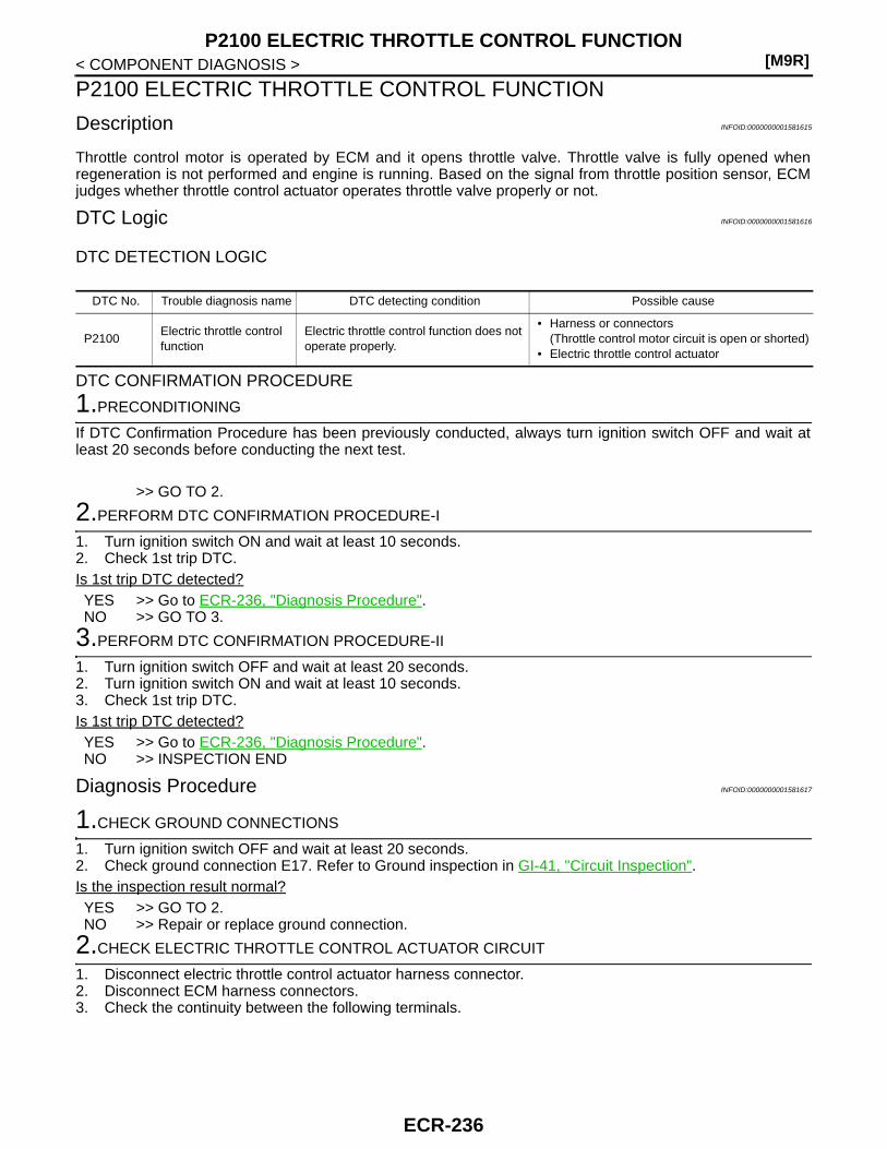
[M9R]P2100 ELECTRIC THROTTLE CONTROL FUNCTION
< COMPONENT DIAGNOSIS >
P2100 ELECTRIC THROTTLE CONTROL FUNCTION
Description INFOID:0000000001581615
Throttle control motor is operated by ECM and it opens throttle valve. Throttle valve is fully opened whenregeneration is not performed and engine is running. Based on the signal from throttle position sensor, ECMjudges whether throttle control actuator operates throttle valve properly or not.
DTC Logic INFOID:0000000001581616
DTC DETECTION LOGIC
DTC CONFIRMATION PROCEDURE
1.PRECONDITIONING
If DTC Confirmation Procedure has been previously conducted, always turn ignition switch OFF and wait atleast 20 seconds before conducting the next test.
>> GO TO 2.
2.PERFORM DTC CONFIRMATION PROCEDURE-I
1. Turn ignition switch ON and wait at least 10 seconds.2. Check 1st trip DTC.Is 1st trip DTC detected?YES >> Go to ECR-236, "Diagnosis Procedure".NO >> GO TO 3.
3.PERFORM DTC CONFIRMATION PROCEDURE-II
1. Turn ignition switch OFF and wait at least 20 seconds.2. Turn ignition switch ON and wait at least 10 seconds.3. Check 1st trip DTC.Is 1st trip DTC detected?YES >> Go to ECR-236, "Diagnosis Procedure".NO >> INSPECTION END
Diagnosis Procedure INFOID:0000000001581617
1.CHECK GROUND CONNECTIONS
1. Turn ignition switch OFF and wait at least 20 seconds.2. Check ground connection E17. Refer to Ground inspection in GI-41, "Circuit Inspection".Is the inspection result normal?YES >> GO TO 2.NO >> Repair or replace ground connection.
2.CHECK ELECTRIC THROTTLE CONTROL ACTUATOR CIRCUIT
1. Disconnect electric throttle control actuator harness connector.2. Disconnect ECM harness connectors.3. Check the continuity between the following terminals.
DTC No. Trouble diagnosis name DTC detecting condition Possible cause
P2100Electric throttle control function
Electric throttle control function does not operate properly.
• Harness or connectors(Throttle control motor circuit is open or shorted)
• Electric throttle control actuator
ECR-236

P2100 ELECTRIC THROTTLE CONTROL FUNCTION[M9R]
C
D
E
F
G
H
I
J
K
L
M
A
CR
N
P
O
< COMPONENT DIAGNOSIS >
E
4. Also check harness for short to ground and short to power. Is the inspection result normal?YES >> GO TO 3.NO >> Repair open circuit or short to ground or short to power in harness or connectors.
3.CHECK THROTRTLE CONTROL MOTOR
Perform ECR-237, "Component Inspection".Is the inspection result normal?YES >> GO TO 4.NO >> Replace electric throttle control actuator.
4.CHECK INTERMITTENT INCIDENT
Refer to GI-39, "Intermittent Incident".
>> Repair open circuit or short to ground or short to power in harness or connectors.
Component Inspection INFOID:0000000001581618
1.CHECK ELECTRIC THROTTLE CONTROL MOTOR
1. Reconnect all harness connectors disconnected.2. Check the voltage between ECM harness connectors terminals under the following conditions.
Electric throttle control actuator ECMContinuity
Connector Terminal Connector Terminal
F148
4
F132
91 Existed
92 Not existed
591 Not existed
92 Existed
(+) (−)Condition Voltage
Connector Terminal Connector Terminal
F132
91(Throttle control
motor)E121
128(ECM ground)
[Engine is running]• Warm-up condition• Idle speed
0 - 2 V
[Ignition switch: OFF]• For 20 seconds after
turning ignition switch OFF
0 - 2 V
[Ignition switch: OFF]• More than 20 seconds
after turning ignition switch OFF
0.1 V
92(Throttle control
motor)
[Engine is running]• Warm-up condition• Idle speed
0 V
JMBIA0547GB
JMBIA0548GB
ECR-237

[M9R]P2100 ELECTRIC THROTTLE CONTROL FUNCTION
< COMPONENT DIAGNOSIS >Is the inspection result normal?YES >> INSPECTION ENDNO >> GO TO 2.
2.REPLACE ELECTRIC THROTTLE CONTROL ACTUATOR
1. Replace electric throttle control actuator.2. Perform ECR-238, "Special Repair Requirement".
>> INSPECTION END
Special Repair Requirement INFOID:0000000001581619
1.PERFORM THROTTLE VALVE CLOSED POSITION LEARNING VALUE CLEAR
Refer to ECR-16, "THROTTLE VALVE CLOSED POSITION LEARNING VALUE CLEAR : Special RepairRequirement"
>> GO TO 2.
2.PERFORM THROTTLE VALVE CLOSED POSITION LEARNING
Refer to ECR-16, "THROTTLE VALVE CLOSED POSITION LEARNING : Special Repair Requirement"
>> END
ECR-238

P2101 ELECTRIC THROTTLE CONTROL FUNCTION[M9R]
C
D
E
F
G
H
I
J
K
L
M
A
CR
N
P
O
< COMPONENT DIAGNOSIS >
E
P2101 ELECTRIC THROTTLE CONTROL FUNCTION
Description INFOID:0000000001581620
Electric throttle cotnrol actuator consists of the following two components, throttle control motor with gearwhich operates throttle valve, throttle position sensor which detects throttle position sensor. Throttle valve isfully opened when regereration is not performed and engine is running. The valve is closed to perform regen-eration and to perform smooth engine stop when the ignition switch is turned OFF. Throttle position sensordetects the opening angle of throttle valve and converts the angle into a voltage signal. Based on the signal,ECM judges whether throttle control actuator operates throttle valve properly or not.
DTC Logic INFOID:0000000001581621
DTC DETECTION LOGICNOTE:If DTC P2101 is displayed with DTC P0606, first perform the trouble diagnosis for DTC P0606. Refer toECR-201, "DTC Logic".
DTC CONFIRMATION PROCEDURE
1.PRECONDITIONING
If DTC Confirmation Procedure has been previously conducted, always turn ignition switch OFF and wait atleast 20 seconds before conducting the next test.
>> GO TO 2.
2.PERFORM DTC CONFIRMATION PROCEDURE
1. Turn ignition switch ON and wait at least 10 seconds.2. Check 1st trip DTC.Is 1st trip DTC detected?YES >> Go to ECR-239, "Diagnosis Procedure".NO >> INSPECTION END
Diagnosis Procedure INFOID:0000000001581622
1.CHECK GROUND CONNECTIONS
1. Turn ignition switch OFF and wait at least 20 seconds.2. Check ground connection E17. Refer to Ground inspection in GI-41, "Circuit Inspection".Is the inspection result normal?YES >> GO TO 2.NO >> Repair or replace ground connection.
2.CHECK ELECTRIC THROTTLE CONTROL ACTUATOR CIRCUIT-I
1. Disconnect electric throttle control actuator harness connector.2. Disconnect ECM harness connectors.3. Check the continuity between electric throttle control actuator harness connector and ECM harness con-
nector.
DTC No. Trouble diagnosis name DTC detecting condition Possible cause
P2101Electric throttle control actuator performance
Electric throttle control actuator does not functions properly.
• Harness or connectors(Electric throttle control actuator circuit is open or shorted.)
• Electric throttle control actuator
ECR-239

[M9R]P2101 ELECTRIC THROTTLE CONTROL FUNCTION
< COMPONENT DIAGNOSIS >
4. Also check harness for short to ground and short to power. Is the inspection result normal?YES >> GO TO 3.NO >> Repair open circuit or short to ground or short to power in harness or connectors.
3.CHECK ELECTRIC THROTTLE CONTROL ACTUATOR CIRCUIT-II
1. Check the continuity between electric throttle control actuator harness connector and ECM harness con-nector.
2. Also check harness for short to ground and short to power. Is the inspection result normal?YES >> GO TO 4.NO >> Repair open circuit or short to ground or short to power in harness or connectors.
4.CHECK THROTRTLE CONTROL MOTOR
Perform ECR-240, "Component Inspection".Is the inspection result normal?YES >> GO TO 5.NO >> Replace electric throttle control actuator.
5.CHECK INTERMITTENT INCIDENT
Refer to GI-39, "Intermittent Incident".
>> Repair open circuit or short to ground or short to power in harness or connectors.
Component Inspection INFOID:0000000001581623
1.CHECK ELECTRIC THROTTLE CONTROL MOTOR
1. Reconnect all harness connectors disconnected.2. Check the voltage between ECM harness connectors terminals under the following conditions.
Electric throttle control actuator ECMContinuity
Connector Terminal Connector Terminal
F148
1
F132
85
Existed3 75
6 83
Electric throttle control actuator ECMContinuity
Connector Terminal Connector Terminal
F1484
F13291
Existed5 92
ECR-240
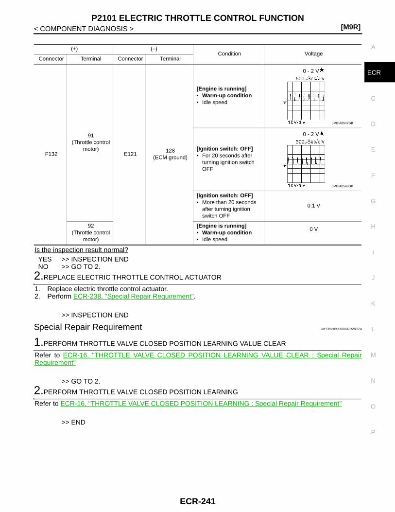
P2101 ELECTRIC THROTTLE CONTROL FUNCTION[M9R]
C
D
E
F
G
H
I
J
K
L
M
A
CR
N
P
O
< COMPONENT DIAGNOSIS >
E
Is the inspection result normal?YES >> INSPECTION ENDNO >> GO TO 2.
2.REPLACE ELECTRIC THROTTLE CONTROL ACTUATOR
1. Replace electric throttle control actuator.2. Perform ECR-238, "Special Repair Requirement".
>> INSPECTION END
Special Repair Requirement INFOID:0000000001581624
1.PERFORM THROTTLE VALVE CLOSED POSITION LEARNING VALUE CLEAR
Refer to ECR-16, "THROTTLE VALVE CLOSED POSITION LEARNING VALUE CLEAR : Special RepairRequirement"
>> GO TO 2.
2.PERFORM THROTTLE VALVE CLOSED POSITION LEARNING
Refer to ECR-16, "THROTTLE VALVE CLOSED POSITION LEARNING : Special Repair Requirement"
>> END
(+) (−)Condition Voltage
Connector Terminal Connector Terminal
F132
91(Throttle control
motor)E121
128(ECM ground)
[Engine is running]• Warm-up condition• Idle speed
0 - 2 V
[Ignition switch: OFF]• For 20 seconds after
turning ignition switch OFF
0 - 2 V
[Ignition switch: OFF]• More than 20 seconds
after turning ignition switch OFF
0.1 V
92(Throttle control
motor)
[Engine is running]• Warm-up condition• Idle speed
0 V
JMBIA0547GB
JMBIA0548GB
ECR-241

[M9R]P2120 APP SENSOR
< COMPONENT DIAGNOSIS >
P2120 APP SENSOR
Description INFOID:0000000001581625
The accelerator pedal position sensor is installed on the upper endof the accelerator pedal assembly. The sensors detect the accelera-tor pedal position and sends a signal to the ECM. The ECM uses thesignal to determine the amount of fuel to be injected.
DTC Logic INFOID:0000000001581626
DTC DETECTION LOGIC
DTC CONFIRMATION PROCEDURE
1.PRECONDITIONING
If DTC Confirmation Procedure has been previously conducted, always turn ignition switch OFF and wait atleast 20 seconds before conducting the next test.
>> GO TO 2.
2.PERFORM DTC CONFIRMATION PROCEDURE-I
1. Turn ignition switch ON and wait at least 5 seconds.2. Check 1st trip DTC.Is 1st trip DTC detected?YES >> Go to ECR-242, "Diagnosis Procedure".NO >> GO TO 3.
3.PERFORM DTC CONFIRMATION PROCEDURE-II
1. Depress accelerator pedal slowly spending 5 seconds, and then release it slowly spending 5 seconds.2. Check 1st trip DTC.Is 1st trip DTC detected?YES >> Go to ECR-242, "Diagnosis Procedure".NO >> INSPECTION END
Diagnosis Procedure INFOID:0000000001581627
1.CHECK GROUND CONNECTIONS
1. Turn ignition switch OFF and wait at least 20 seconds.2. Check ground connection E17. Refer to Ground inspection in GI-41, "Circuit Inspection".Is the inspection result normal?
PBIB1741E
DTC No. Trouble diagnosis name DTC detecting condition Possible cause
P2120
Accelerator pedal position sensor 2 circuit low input
An excessively low voltage from the sensor is sent to ECM.
• Harness or connectors(Accelerator pedal position sensor circuit is open or shorted.)
• Accelerator pedal position sensor(APP sensor 1 and 2)
Accelerator pedal position sensor 2 circuit high input
An excessively high voltage from the sensor is sent to ECM.
Accelerator pedal position sensor 1, 2 signal correlation
The correlation between APP sensor 1 signal and APP sensor 2 signal is out of the normal range.
ECR-242
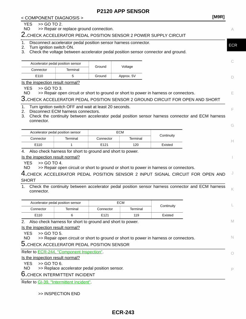
P2120 APP SENSOR[M9R]
C
D
E
F
G
H
I
J
K
L
M
A
CR
N
P
O
< COMPONENT DIAGNOSIS >
E
YES >> GO TO 2.NO >> Repair or replace ground connection.
2.CHECK ACCELERATOR PEDAL POSITION SENSOR 2 POWER SUPPLY CIRCUIT
1. Disconnect accelerator pedal position sensor harness connector.2. Turn ignition switch ON.3. Check the voltage between accelerator pedal position sensor connector and ground.
Is the inspection result normal?YES >> GO TO 3.NO >> Repair open circuit or short to ground or short to power in harness or connectors.
3.CHECK ACCELERATOR PEDAL POSITION SENSOR 2 GROUND CIRCUIT FOR OPEN AND SHORT
1. Turn ignition switch OFF and wait at least 20 seconds.2. Disconnect ECM harness connectors.3. Check the continuity between accelerator pedal position sensor harness connector and ECM harness
connector.
4. Also check harness for short to ground and short to power. Is the inspection result normal?YES >> GO TO 4.NO >> Repair open circuit or short to ground or short to power in harness or connectors.
4.CHECK ACCELERATOR PEDAL POSITION SENSOR 2 INPUT SIGNAL CIRCUIT FOR OPEN ANDSHORT
1. Check the continuity between accelerator pedal position sensor harness connector and ECM harnessconnector.
2. Also check harness for short to ground and short to power. Is the inspection result normal?YES >> GO TO 5.NO >> Repair open circuit or short to ground or short to power in harness or connectors.
5.CHECK ACCELERATOR PEDAL POSITION SENSOR
Refer to ECR-244, "Component Inspection".Is the inspection result normal?YES >> GO TO 6.NO >> Replace accelerator pedal position sensor.
6.CHECK INTERMITTENT INCIDENT
Refer to GI-39, "Intermittent Incident".
>> INSPECTION END
Accelerator pedal position sensorGround Voltage
Connector Terminal
E110 5 Ground Approx. 5V
Accelerator pedal position sensor ECMContinuity
Connector Terminal Connector Terminal
E110 1 E121 120 Existed
Accelerator pedal position sensor ECMContinuity
Connector Terminal Connector Terminal
E110 6 E121 119 Existed
ECR-243

[M9R]P2120 APP SENSOR
< COMPONENT DIAGNOSIS >
Component Inspection INFOID:0000000001581628
1.CHECK ACCELERATOR PEDAL POSITION SENSOR
1. Turn ignition switch OFF.2. Reconnect all harness connectors disconnected.3. Turn ignition switch ON.4. Check the voltage between ECM harness connector terminals as follows.
Is the inspection result normal?YES >> INSPECTION ENDNO >> Replace accelerator pedal assembly.
ECM ECMCondition Voltage
Connector Terminal Connector Terminal
E121
126(APP sensor 1)
E121
127(Sensor ground)
Accelerator pedal
Fully released 0.6 - 4.6 V
Fully depressed Less than 5 V
119(APP sensor 2)
120(Sensor ground)
Fully released More than 0.3 V
Fully depressed Less than 2.5 V
ECR-244

P2146, P2149 FUEL INJECTOR POWER SUPPLY[M9R]
C
D
E
F
G
H
I
J
K
L
M
A
CR
N
P
O
< COMPONENT DIAGNOSIS >
E
P2146, P2149 FUEL INJECTOR POWER SUPPLY
Component Description INFOID:0000000001581629
The fuel injector is a small, precise solenoid valve. When the ECMsupplies a ground to the fuel injector circuit, the coil in the fuel injec-tor is energized. The energized coil pulls the needle valve back andallows fuel to flow through the fuel injector into the cylinder. Theamount of fuel injected depends upon the injection pulse duration.Pulse duration is the length of time the fuel injector remains open.The ECM controls the injection pulse duration based on engine fuelneeds.
DTC Logic INFOID:0000000001581630
DTC DETECTION LOGIC
DTC CONFIRMATION PROCEDURE
1.PRECONDITIONING
If DTC Confirmation Procedure has been previously conducted, always turn ignition switch OFF and wait atleast 20 seconds before conducting the next test.
>> GO TO 2.
2.PERFORM DTC CONFIRMATION PROCEDURE
1. Start engine and let it idle for at least 10 seconds.2. Check 1st trip DTC.Is 1st trip DTC detected?YES >> Go to ECR-245, "Diagnosis Procedure".NO >> INSPECTION END
Diagnosis Procedure INFOID:0000000001581631
1.CHECK FUEL INJECTOR POWER SUPPLY CIRCUIT FOR OPEN AND SHORT
1. Turn ignition switch OFF and wait at least 20 seconds.2. Disconnect ECM harness connector.3. Disconnect fuel injector harness connector.4. Check the continuity between fuel injector harness connector and ECM harness connector.
5. Also check harness for short to ground and short to power.
PBIB0465E
DTC No. Trouble diagnosis name DTC detecting condition Possible cause
P2146No. 1 and 4 cylinder fuel injector power supply circuit open
An improper voltage signal is sent to ECM through No. 1 and 4 cylinder fuel injector. • Harness or connectors
(The fuel injector circuit is open.)P2149
No. 2 and 3 cylinder fuel injector power supply circuit open
An improper voltage signal is sent to ECM through No. 2 and 3 cylinder fuel injector.
Fuel injector ECMContinuity
Cylinder Connector Terminal Connector Terminal
1 F144 1
F131
6
Existed2 F145 1 7
3 F146 1 8
4 F147 1 5
ECR-245

[M9R]P2146, P2149 FUEL INJECTOR POWER SUPPLY
< COMPONENT DIAGNOSIS >Is the inspection result normal?YES >> GO TO 2.NO >> Repair open circuit or short to ground or short to power in harness or connectors.
2.CHECK INTERMITTENT INCIDENT
Refer to GI-39, "Intermittent Incident".
>> INSPECTION END
ECR-246

P2226 BARO SENSOR[M9R]
C
D
E
F
G
H
I
J
K
L
M
A
CR
N
P
O
< COMPONENT DIAGNOSIS >
E
P2226 BARO SENSOR
Description INFOID:0000000001581632
The barometric pressure sensor is built into ECM. The sensordetects ambient barometric pressure and sends the voltage signal tothe microcomputer.
DTC Logic INFOID:0000000001581633
DTC DETECTION LOGIC
DTC CONFIRMATION PROCEDURE
1.PRECONDITIONING
If DTC Confirmation Procedure has been previously conducted, always turn ignition switch OFF and wait atleast 20 seconds before conducting the next test.
>> GO TO 2.
2.PERFORM DTC CONFIRMATION PROCEDURE FOR MALFUNCTION
1. Turn ignition switch ON.2. Check 1st trip DTC.Is 1st trip DTC detected?YES >> Go to ECR-247, "Diagnosis Procedure".NO >> INSPECTION END
Diagnosis Procedure INFOID:0000000001581634
1.INSPECTION START
With CONSULT-III1. Turn ignition switch ON.2. Select “SELF-DIAG RESULTS” mode with CONSULT-III.3. Touch “ERASE”.4. Perform DTC CONFIRMATION PROCEDURE.
See ECR-247, "DTC Logic".With GST
1. Turn ignition switch ON.2. Select Service $04 with GST.3. Perform DTC CONFIRMATION PROCEDURE.
See ECR-247, "DTC Logic".Is the 1st trip DTC P2226 displayed again?YES >> GO TO 2.
MBIB1517E
DTC No. Trouble diagnosis name DTC detecting condition Possible cause
P2226Barometric pressure sensor circuit
An excessively low voltage from the barometric pressure sensor (built-into ECM) is sent to ECM.
• ECMAn excessively high voltage from the barometric pressure sensor (built-into ECM) is sent to ECM.
ECR-247

[M9R]P2226 BARO SENSOR
< COMPONENT DIAGNOSIS >NO >> INSPECTION END
2.REPLACE ECM
1. Replace ECM.2. Go to ECR-12, "ADDITIONAL SERVICE WHEN REPLACING CONTROL UNIT : Special Repair Require-
ment".
>> INSPECTION END
ECR-248

P2231 A/F SENSOR 1[M9R]
C
D
E
F
G
H
I
J
K
L
M
A
CR
N
P
O
< COMPONENT DIAGNOSIS >
E
P2231 A/F SENSOR 1
Description INFOID:0000000001581635
Air fuel ratio (A/F) sensor 1 (1) is installed on the upstream of the oxi-dation catalyst. A/F sensor 1 measures the oxygen level in theexhaust gas and converts it into a voltage signal. A/F sensor 1 sendsthe signal to ECM. Based on the signal from A/F sensor 1, ECM cal-culates the air fuel mixture ratio. ECM uses the calculated ratio forthe DPF regeneration control.A heater is integrated in A/F sensor 1 to ensure the required operat-ing temperature.
DTC Logic INFOID:0000000001581636
DTC DETECTION LOGIC
Diagnosis Procedure INFOID:0000000001581637
1.CHECK GROUND CONNECTIONS
1. Turn ignition switch OFF and wait at least 20 seconds.2. Check ground connection E17. Refer to Ground inspection in GI-41, "Circuit Inspection".Is the inspection result normal?YES >> GO TO 2.NO >> Repair or replace ground connections.
2.CHECK AIR FUEL RATIO (A/F) SENSOR 1 POWER SUPPLY CIRCUIT
1. Disconnect A/F sensor 1 harness connector.2. Turn ignition switch ON.3. Check the voltage between A/F sensor 1 harness connector and ground.
OK or NGOK >> GO TO 4.NG >> GO TO 3.
3.DETECT MALFUNCTIONING PART
Check the following.• Harness connectors E7, F121• Harness for open or short between A/F sensor 1 and IPDM E/R• Harness for open or short between A/F sensor 1 and ECM
>> Repair or replace harness or connectors.
4.CHECK A/F SENSOR 1 INPUT SIGNAL CIRCUIT FOR OPEN AND SHORT
1. Turn ignition switch OFF and wait at least 20 seconds.
PBIB3183E
DTC No. Trouble diagnosis name DTC detecting condition Possible Cause
P2231Air fuel ratio (A/F) sensor 1 circuit
The A/F signal computed by ECM from the air fuel ratio sensor 1 signal is out of the specified range.
• Harness or connectors(The air fuel ratio sensor 1 circuit is shorted.)
• Air fuel ratio sensor 1
A/F sensor 1Ground Voltage
Connector Terminal
F141 4 Ground Battery voltage
ECR-249
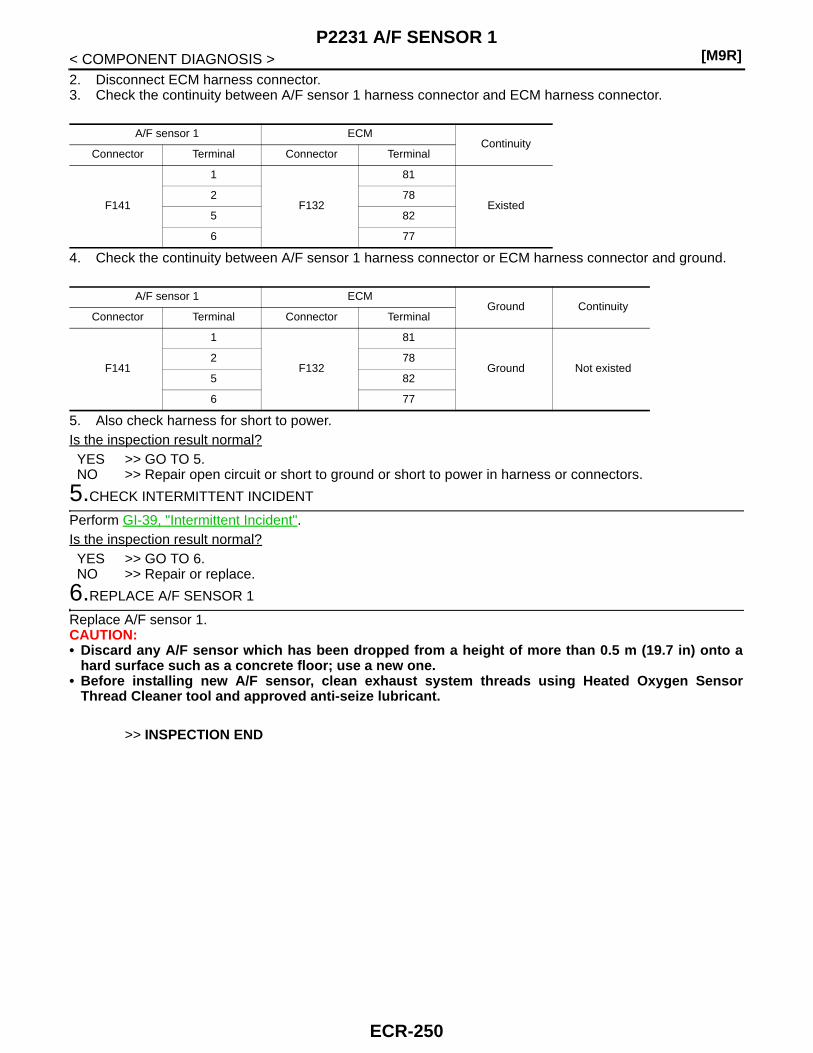
[M9R]P2231 A/F SENSOR 1
< COMPONENT DIAGNOSIS >2. Disconnect ECM harness connector.3. Check the continuity between A/F sensor 1 harness connector and ECM harness connector.
4. Check the continuity between A/F sensor 1 harness connector or ECM harness connector and ground.
5. Also check harness for short to power.Is the inspection result normal?YES >> GO TO 5.NO >> Repair open circuit or short to ground or short to power in harness or connectors.
5.CHECK INTERMITTENT INCIDENT
Perform GI-39, "Intermittent Incident".Is the inspection result normal?YES >> GO TO 6.NO >> Repair or replace.
6.REPLACE A/F SENSOR 1
Replace A/F sensor 1.CAUTION:• Discard any A/F sensor which has been dropped from a height of more than 0.5 m (19.7 in) onto a
hard surface such as a concrete floor; use a new one.• Before installing new A/F sensor, clean exhaust system threads using Heated Oxygen Sensor
Thread Cleaner tool and approved anti-seize lubricant.
>> INSPECTION END
A/F sensor 1 ECMContinuity
Connector Terminal Connector Terminal
F141
1
F132
81
Existed2 78
5 82
6 77
A/F sensor 1 ECMGround Continuity
Connector Terminal Connector Terminal
F141
1
F132
81
Ground Not existed2 78
5 82
6 77
ECR-250
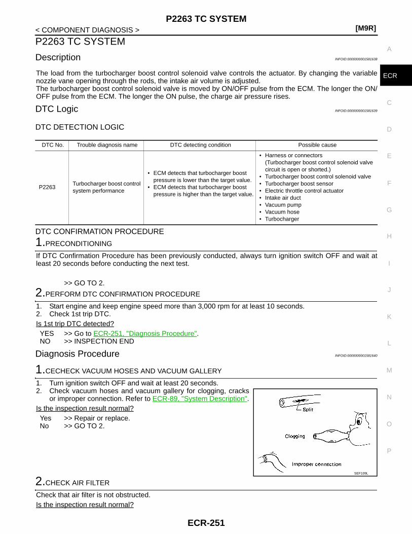
P2263 TC SYSTEM[M9R]
C
D
E
F
G
H
I
J
K
L
M
A
CR
N
P
O
< COMPONENT DIAGNOSIS >
E
P2263 TC SYSTEM
Description INFOID:0000000001581638
The load from the turbocharger boost control solenoid valve controls the actuator. By changing the variablenozzle vane opening through the rods, the intake air volume is adjusted.The turbocharger boost control solenoid valve is moved by ON/OFF pulse from the ECM. The longer the ON/OFF pulse from the ECM. The longer the ON pulse, the charge air pressure rises.
DTC Logic INFOID:0000000001581639
DTC DETECTION LOGIC
DTC CONFIRMATION PROCEDURE
1.PRECONDITIONING
If DTC Confirmation Procedure has been previously conducted, always turn ignition switch OFF and wait atleast 20 seconds before conducting the next test.
>> GO TO 2.
2.PERFORM DTC CONFIRMATION PROCEDURE
1. Start engine and keep engine speed more than 3,000 rpm for at least 10 seconds.2. Check 1st trip DTC.Is 1st trip DTC detected?YES >> Go to ECR-251, "Diagnosis Procedure".NO >> INSPECTION END
Diagnosis Procedure INFOID:0000000001581640
1.CECHECK VACUUM HOSES AND VACUUM GALLERY
1. Turn ignition switch OFF and wait at least 20 seconds.2. Check vacuum hoses and vacuum gallery for clogging, cracks
or improper connection. Refer to ECR-89, "System Description".Is the inspection result normal?Yes >> Repair or replace.No >> GO TO 2.
2.CHECK AIR FILTER
Check that air filter is not obstructed.Is the inspection result normal?
DTC No. Trouble diagnosis name DTC detecting condition Possible cause
P2263Turbocharger boost control system performance
• ECM detects that turbocharger boost pressure is lower than the target value.
• ECM detects that turbocharger boost pressure is higher than the target value.
• Harness or connectors(Turbocharger boost control solenoid valve circuit is open or shorted.)
• Turbocharger boost control solenoid valve• Turbocharger boost sensor• Electric throttle control actuator• Intake air duct• Vacuum pump• Vacuum hose• Turbocharger
SEF109L
ECR-251

[M9R]P2263 TC SYSTEM
< COMPONENT DIAGNOSIS >Yes >> Repair or replace.No >> GO TO 3.
3.CHECK INTAKE AIR DUCT
Check that intake air duct is not obstructed.Is the inspection result normal?Yes >> Repair or replace.No >> GO TO 4.
4.CHECK VACUUM PUMP
Check vacuum pump.Is the inspection result normal?Yes >> Repair or replace.No >> GO TO 5.
5.CHECK TURBOCHARGER
Check turbocharger.Is the inspection result normal?Yes >> Repair or replace.No >> GO TO 6.
6.CHECK TURBOCHARGER BOOST CONTROL SOLENOID VALVE POWER SUPPLY CIRCUIT
1. Disconnect turbocharger boost control solenoid valve harness connector.2. Turn ignition switch ON.3. Check the voltage between turbocharger boost control solenoid valve harness connector and ground.
Is the inspection result normal?YES >> GO TO 7.NO >> Repair open circuit or short to ground or short to power in harness or connectors.
7.CHECK TURBOCHARGER BOOST CONTROL SOLENOID VALVE OUTPUT SIGNAL CIRCUIT FOROPEN AND SHORT
1. Turn ignition switch OFF and wait at least 20 seconds.2. Disconnect ECM harness connector.3. Check the continuity between turbocharger boost control solenoid valve harness connector and ECM har-
ness connector.
4. Also check harness for short to ground and short to power. Is the inspection result normal?YES >> GO TO 9.NO >> GO TO 8.
8.DETECT MALFUNCTIONING PART
Check the following.• Harness connectors E7, F121• Harness for open and short between turbocharger boost control solenoid valve and ECM
>> Repair open circuit or short to ground or short to power in harness or connectors.
Turbocharger boost control solenoid valveGround Voltage
Connector Terminal
E122 1 Ground Battery voltage
Turbocharger boost control solenoid valve ECMContinuity
Connector Terminal Connector Terminal
E122 2 F132 57 Existed
ECR-252
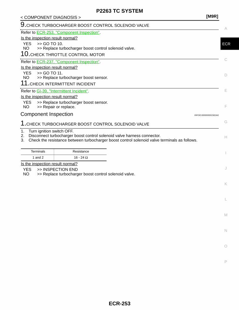
P2263 TC SYSTEM[M9R]
C
D
E
F
G
H
I
J
K
L
M
A
CR
N
P
O
< COMPONENT DIAGNOSIS >
E
9.CHECK TURBOCHARGER BOOST CONTROL SOLENOID VALVE
Refer to ECR-253, "Component Inspection".Is the inspection result normal?YES >> GO TO 10.NO >> Replace turbocharger boost control solenoid valve.
10.CHECK THROTTLE CONTROL MOTOR
Refer to ECR-237, "Component Inspection".Is the inspection result normal?YES >> GO TO 11.NO >> Replace turbocharger boost sensor.
11.CHECK INTERMITTENT INCIDENT
Refer to GI-39, "Intermittent Incident".Is the inspection result normal?YES >> Replace turbocharger boost sensor.NO >> Repair or replace.
Component Inspection INFOID:0000000001581641
1.CHECK TURBOCHARGER BOOST CONTROL SOLENOID VALVE
1. Turn ignition switch OFF.2. Disconnect turbocharger boost control solenoid valve harness connector.3. Check the resistance between turbocharger boost control solenoid valve terminals as follows.
Is the inspection result normal?YES >> INSPECTION ENDNO >> Replace turbocharger boost control solenoid valve.
Terminals Resistance
1 and 2 16 - 24 Ω
ECR-253

[M9R]P2293 FRP CONTROL SYSTEM
< COMPONENT DIAGNOSIS >
P2293 FRP CONTROL SYSTEM
Description INFOID:0000000001581642
Fuel rail pressure (FRP) sensor is installed on the fuel rail. It measures the fuel pressure in the fuel rail. Thesensor sends voltage signal to the ECM. As the pressure increases, the voltage rises. The ECM controls thefuel pressure in the fuel rail by the inlet throttling device. The ECM uses the signal from fuel rail pressure sen-sor as a feedback signal.
DTC Logic INFOID:0000000001581643
DTC DETECTION LOGIC
DTC CONFIRMATION PROCEDURE
1.PRECONDITIONING
If DTC Confirmation Procedure has been previously conducted, always turn ignition switch OFF and wait atleast 20 seconds before conducting the next test.
>> GO TO 2.
2.PERFORM DTC CONFIRMATION PROCEDURE
1. Start engine and let it idle for at least 10 seconds.2. Check 1st trip DTC.Is 1st trip DTC detected?YES >> Go to ECR-254, "Diagnosis Procedure".NO >> INSPECTION END
Diagnosis Procedure INFOID:0000000001581644
1.CHECK FUEL RAIL PRESSURE CONTROL VALVE POWER SUPPLY CIRCUIT
1. Turn ignition switch OFF and wait at least 20 seconds.2. Disconnect fuel rail pressure control valve harness connector.3. Turn ignition switch ON.4. Check the voltage between fuel rail pressure control valve harness connector and ground.
Is the inspection result normal?YES >> GO TO 3.NO >> GO TO 2.
2.DETECT MALFUNCTIONING PART
Check the following.• Harness connector E7, F121• Harness for open or short between IPDM E/R and fuel rail pressure control valve• Harness for open or short between ECM and fuel rail pressure control valve
>> Repair open circuit or short to ground or short to power in harness or connectors.
DTC No. Trouble diagnosis name DTC detecting condition Possible cause
P2294Fuel rail pressure control valve function
Fuel rail pressure is out of the target range.
• Harness or connectors(Fuel rail pressure control valve circuit is open or shorted.)
• Fuel rail pressure control valve
Fuel rail pressure control valveGround Voltage
Connector Terminal
F149 1 Ground Battery voltage
ECR-254

P2293 FRP CONTROL SYSTEM[M9R]
C
D
E
F
G
H
I
J
K
L
M
A
CR
N
P
O
< COMPONENT DIAGNOSIS >
E
3.CHECK FUEL RAIL PRESSURE CONTROL VALVE OUTPUT SIGNAL CIRCUIT FOR OPEN AND SHORT
1. Turn ignition switch OFF and wait at least 20 seconds.2. Disconnect ECM harness connector.3. Check the continuity between fuel rail pressure control valve harness connector and ECM harness con-
nector.
4. Also check harness for short to ground and short to power. Is the inspection result normal?YES >> GO TO 4.NO >> Repair open circuit or short to ground or short to power in harness or connectors.
4.CHECK FUEL RAIL PRESSURE CONTROL VALVE
Refer to ECR-255, "Component Inspection".Is the inspection result normal?Yes >> GO TO 5.No >> Replace fuel rail pressure control valve.
5.CHECK INTERMITTENT INCIDENT
Refer to GI-39, "Intermittent Incident".
>> INSPECTION END
Component Inspection INFOID:0000000001581645
1.CHECK FUEL RAIL PRESSURE CONTROL VALVE
1. Turn ignition switch OFF.2. Disconnect fuel rail pressure control valve harness connector.3. Check resistance between fuel rail pressure control valve terminals as follows.
Is the inspection result normal?YES >> INSPECTION ENDNO >> Replace fuel rail pressure control valve.
Fuel rail pressure control valve ECMContinuity
Connector Terminal Connector Terminal
F149 2 F132 90 Existed
Terminals Resistance
1 and 2 2 - 6 Ω
ECR-255

[M9R]P2294 FRP CONTROL VALVE
< COMPONENT DIAGNOSIS >
P2294 FRP CONTROL VALVE
Description INFOID:0000000001581646
Fuel rail pressure control valve controls fuel rail pressure based on fuel rail pressure sensor signal. When thefuel pressure in fuel rail increases to excessively high, ECM controls fuel rail pressure control valve to carryexcess fuel to the return hose.
DTC Logic INFOID:0000000001581647
DTC DETECTION LOGIC
DTC CONFIRMATION PROCEDURE
1.PRECONDITIONING
If DTC Confirmation Procedure has been previously conducted, always turn ignition switch OFF and wait atleast 20 seconds before conducting the next test.
>> GO TO 2.
2.PERFORM DTC CONFIRMATION PROCEDURE
1. Turn ignition switch ON and wait at least 10 seconds.2. Check 1st trip DTC.Is 1st trip DTC detected?YES >> Go to ECR-256, "Diagnosis Procedure".NO >> INSPECTION END
Diagnosis Procedure INFOID:0000000001581648
1.CHECK FUEL RAIL PRESSURE CONTROL VALVE POWER SUPPLY CIRCUIT
1. Turn ignition switch OFF and wait at least 20 seconds.2. Disconnect fuel rail pressure control valve harness connector.3. Turn ignition switch ON.4. Check the voltage between fuel rail pressure control valve harness connector and ground.
Is the inspection result normal?YES >> GO TO 3.NO >> GO TO 2.
2.DETECT MALFUNCTIONING PART
Check the following.• Harness connector E7, F121• Harness for open or short between IPDM E/R and fuel rail pressure control valve• Harness for open or short between ECM and fuel rail pressure control valve
DTC No. Trouble diagnosis name DTC detecting condition Possible cause
P2294Fuel rail pressure control valve circuit
An excessively low voltage from the control valve is sent to ECM.
• Harness or connectors(Fuel rail pressure control valve circuit is open or shorted.)
• Fuel rail pressure control valve
An excessively high voltage from the control valve is sent to ECM.
An improper voltage is sent to ECM through control valve.
Fuel rail pressure control valveGround Voltage
Connector Terminal
F149 1 Ground Battery voltage
ECR-256

P2294 FRP CONTROL VALVE[M9R]
C
D
E
F
G
H
I
J
K
L
M
A
CR
N
P
O
< COMPONENT DIAGNOSIS >
E
>> Repair open circuit or short to ground or short to power in harness or connectors.
3.CHECK FUEL RAIL PRESSURE CONTROL VALVE OUTPUT SIGNAL CIRCUIT FOR OPEN AND SHORT
1. Turn ignition switch OFF and wait at least 20 seconds.2. Disconnect ECM harness connector.3. Check the continuity between fuel rail pressure control valve harness connector and ECM harness con-
nector.
4. Also check harness for short to ground and short to power. Is the inspection result normal?YES >> GO TO 4.NO >> Repair open circuit or short to ground or short to power in harness or connectors.
4.CHECK FUEL RAIL PRESSURE CONTROL VALVE
Refer to ECR-257, "Component Inspection".Is the inspection result normal?Yes >> GO TO 5.No >> Replace fuel rail pressure control valve.
5.CHECK INTERMITTENT INCIDENT
Refer to GI-39, "Intermittent Incident".
>> INSPECTION END
Component Inspection INFOID:0000000001581649
1.CHECK FUEL RAIL PRESSURE CONTROL VALVE
1. Turn ignition switch OFF.2. Disconnect fuel rail pressure control valve harness connector.3. Check resistance between fuel rail pressure control valve terminals as follows.
Is the inspection result normal?YES >> INSPECTION ENDNO >> Replace fuel rail pressure control valve.
Fuel rail pressure control valve ECMContinuity
Connector Terminal Connector Terminal
F149 2 F132 90 Existed
Terminals Resistance
1 and 2 0.002 - 1 kΩ
ECR-257
[M9R]P2299 ACCELERATOR/BRAKE PEDAL POSITION INCONSISTENCY
< COMPONENT DIAGNOSIS >
P2299 ACCELERATOR/BRAKE PEDAL POSITION INCONSISTENCY
DTC Logic INFOID:0000000001581650
DTC DETECTION LOGIC
1.PRECONDITIONING
If DTC Confirmation Procedure has been previously conducted, always turn ignition switch OFF and wait atleast 20 seconds before conducting the next test.
>> GO TO 2.
2.PERFORM DTC CONFIRMATION PROCEDURE
1. Start engine and let it idle for at least 30 seconds.2. Keep engine speed at 2,000 rpm for at least 30 seconds.3. Release accelerator pedal and apply service brake for at least 30 seconds.4. Check 1st trip DTC.Is 1st trip DTC detected?YES >> Go to ECR-258, "Diagnosis Procedure".NO >> INSPECTION END
Diagnosis Procedure INFOID:0000000001581651
1.CHECK GROUND CONNECTIONS
1. Turn ignition switch OFF and wait at least 20 seconds.2. Check ground connection E17. Refer to Ground inspection in GI-41, "Circuit Inspection".Is the inspection result normal?YES >> GO TO 2.NO >> Repair or replace ground connection.
2.CHECK STOP LAMP SWITCH CIRCUIT
1. Turn ignition switch ON.2. Check the voltage between ECM harness connector terminals as follows.
Is the inspection result normal?YES >> GO TO 3.NO >> GO TO 8.
DTC No. Trouble diagnosis name DTC detecting condition Possible cause
P2299
Accelerator pedal/brake pedal po-sition inconsistency
Accelerator pedal position sensor does not operate properly
• Harness or connectors(Accelerator pedal position sensor circuit is open or shorted.)(Stop lamp switch circuit is open or shorted.)
• Accelerator pedal position sensor (APP sensor 1 and 2)
• Stop lamp switch • Accelerator pedal installation
Accelerator pedal position sensor circuit
No signal from accelerator pedal position sensor is sent to ECM
• Harness or connectors(Accelerator pedal position sensor circuit is open or shorted.)
• Accelerator pedal position sensor (APP sensor 1 and 2)
(+) (−)Condition Voltage
Connector Terminal Connector Terminal
E121 116 E121 128 Brake pedalFully released Battery voltage
Slightly depressed 0 V
ECR-258
P2299 ACCELERATOR/BRAKE PEDAL POSITION INCONSISTENCY[M9R]
C
D
E
F
G
H
I
J
K
L
M
A
CR
N
P
O
< COMPONENT DIAGNOSIS >
E
3.CHECK ACCELERATOR PEDAL POSITION SENSOR CIRCUIT
1. Check the voltage between ECM harness connector and ground.
Is the inspection result normal?YES >> GO TO 12.NO >> GO TO 4.
4.CHECK ACCELERATOR PEDAL POSITION SENSOR POWER SUPPLY CIRCUIT
1. Turn ignition switch OFF and wait at least 20 seconds.2. Disconnect accelerator pedal position sensor harness connector.3. Turn ignition switch ON.4. Check the voltage between accelerator pedal position sensor harness connector and ground.
Is the inspection result normal?YES >> GO TO 5.NO >> Repair open circuit or short to ground or short to power in harness or connectors.
5.CHECK ACCELERATOR PEDAL POSITION SENSOR GROUND CIRCUIT FOR OPEN AND SHORT
1. Turn ignition switch OFF and wait at least 20 seconds.2. Disconnect ECM harness connector.3. Check the continuity between accelerator pedal position sensor harness connector and ECM harness
connector.
4. Also check harness for short to ground and short to power. Is the inspection result normal?YES >> GO TO 6.NO >> Repair open circuit or short to ground or short to power in harness or connectors.
6.CHECK ACCELERATOR PEDAL POSITION SENSOR INPUT SIGNAL CIRCUIT FOR OPEN AND SHORT
1. Check the continuity between accelerator pedal position sensor harness connector and ECM harnessconnector.
2. Also check harness for short to ground and short to power.
(+) (−)Condition Voltage
Connector Terminal Connector terminal
E121
119
E121 128Accelerator pedal
Fully released 0.3 - 0.6 V
Slightly depressed 1.95 - 2.4 V
126Fully released 0.6 - 0.9 V
Slightly depressed 3.9 - 4.7 V
Accelerator pedal position sensorGround Voltage
Sensor Connector Terminal
1E110
4Ground Approx. 5V
2 5
Accelerator pedal position sensor ECMContinuity
Sensor Connector Terminal Connector Terminal
1E110
2E121
127Existed
2 1 120
Accelerator pedal position sensor ECMContinuity
Sensor Connector Terminal Connector Terminal
1E110
3E121
126Existed
2 6 119
ECR-259

[M9R]P2299 ACCELERATOR/BRAKE PEDAL POSITION INCONSISTENCY
< COMPONENT DIAGNOSIS >Is the inspection result normal?YES >> GO TO 7.NO >> Repair open circuit or short to ground or short to power in harness or connectors.
7.CHECK ACCELERATOR PEDAL POSITION SENSOR
Refer to ECR-160, "Component Inspection".Is the inspection result normal?YES >> GO TO 12.NO >> Replace accelerator pedal position sensor.
8.CHECK STOP LAMP SWITCH POWER SUPPLY CIRCUIT
1. Turn ignition switch OFF and wait at least 20 seconds.2. Disconnect stop lamp switch harness connector.3. Turn ignition switch ON.4. Check the voltage between stop lamp switch harness connector and ground.
Is the inspection result normal?YES >> GO TO 10.NO >> GO TO 9.
9.DETECT MALFUNCTIONING PART
Check the following.• Harness connector E105, M77• 10A fuse (No. 4)• Harness for open or short between fuse and stop lamp switch
>> Repair open circuit or short to ground or short to power in harness or connectors.
10.CHECK STOP LAMP SWITCH INPUT SIGNAL CIRCUIT FOR OPEN AND SHORT
1. Turn ignition switch OFF and wait at least 20 seconds.2. Disconnect ECM harness connector.3. Check the continuity between stop lamp switch harness connector and ECM harness connector.
4. Also check harness for short to ground and short to power. Is the inspection result normal?YES >> GO TO 11.NO >> Repair open circuit or short to ground or short to power in harness or connectors.
11.CHECK STOP LAMP SWITCH
Refer to ECR-197, "Component Inspection".Is the inspection result normal?YES >> GO TO 12.NO >> Replace stop lamp switch.
12.CHECK INTERMITTENT INCIDENT
Refer to GI-39, "Intermittent Incident".
>> INSPECTION END
Stop lamp switchGround Voltage
Connector Terminal
E118 4 Ground Battery voltage
Stop lamp switch ECMContinuity
Connector Terminal Connector Terminal
E118 3 E121 116 Existed
ECR-260

P2425 EGR COOLER BYPASS VALVE CONTROL SOLENOID VALVE[M9R]
C
D
E
F
G
H
I
J
K
L
M
A
CR
N
P
O
< COMPONENT DIAGNOSIS >
E
P2425 EGR COOLER BYPASS VALVE CONTROL SOLENOID VALVE
Description INFOID:0000000001581652
EGR cooler bypass valve control solenoid valve controls vacuum signal to the EGR cooler bypass valve con-trol actuator. ERG amount is controlled by changing the EGR cooler bypass valve opening using the rod. EGRcooler bypass valve control solenoid valve is operated by ON/OFF signals (pulse signals) sent from ECM. Thelonger is the ON pulse duration, the larger becomes the bypass gas volume.
DTC Logic INFOID:0000000001581653
DTC DETECTION LOGIC
DTC CONFIRMATION PROCEDURE
1.PRECONDITIONING
If DTC Confirmation Procedure has been previously conducted, always turn ignition switch OFF and wait atleast 20 seconds before conducting the next test.
>> GO TO 2.
2.PERFORM DTC CONFIRMATION PROCEDURE
1. Start engine and let it idle for at least 10 seconds.2. Check 1st trip DTC.Is 1st trip DTC detected?YES >> Go to ECR-261, "Diagnosis Procedure".NO >> INSPECTION END
Diagnosis Procedure INFOID:0000000001581654
1.CHECK EGR COOLER BYPASS VALVE CONTROL SOLENOID VALVE POWER SUPPLY CIRCUIT
1. Turn ignition switch OFF and wait at least 20 seconds.2. Disconnect EGR cooler bypass valve control solenoid valve harness connector.3. Turn ignition switch ON.4. Check the voltage between EGR cooler bypass valve control solenoid valve harness connector and
ground.
Is the inspection result normal?YES >> GO TO 3.NO >> GO TO 2.
2.DETECT MALFUNCTIONING PART
Check the following.• Harness for open or short between IPDM E/R and EGR cooler bypass valve control solenoid valve• Harness for open or short between ECM and EGR cooler bypass valve control solenoid valve
DTC No. Trouble diagnosis name DTC detecting condition Possible cause
P2425EGR cooler bypass valve control solenoid valve circuit
An excessively low voltage from the solenoid valve is sent to ECM. • Harness or connectors
(EGR cooler bypass valve control solenoid valve circuit is open or shorted.)
• EGR cooler bypass valve control solenoid valve
An excessively high voltage from the solenoid valve is sent to ECM.
An improper voltage is sent to ECM through solenoid valve.
EGR cooler bypass valve control solenoid valveGround Voltage
Connector Terminal
F151 1 Ground Battery voltage
ECR-261

[M9R]P2425 EGR COOLER BYPASS VALVE CONTROL SOLENOID VALVE
< COMPONENT DIAGNOSIS >>> Repair open circuit or short to ground or short to power in harness or connectors.
3.CHECK EGR COOLER BYPASS VALVE CONTROL SOLENOID VALVE OUTPUT SIGNAL CIRCUIT FOROPEN AND SHORT
1. Turn ignition switch OFF and wait at least 20 seconds.2. Disconnect ECM harness connector.3. Check the continuity between EGR cooler bypass valve control solenoid valve harness connector and
ECM harness connector.
4. Also check harness for short to ground and short to power. Is the inspection result normal?YES >> GO TO 4.NO >> Repair open circuit or short to ground or short to power in harness or connectors.
4.CHECK EGR COOLER BYPASS VALVE CONTROL SOLENOID VALVE
Refer to ECR-262, "Component Inspection".Is the inspection result normal?YES >> GO TO 5.NO >> Replace EGR cooler bypass valve control solenoid valve.
5.CHECK INTERMITTENT INCIDENT
Refer to GI-39, "Intermittent Incident".
>> INSPECTION END
Component Inspection INFOID:0000000001581655
1.CHECK EGR COOLER BYPASS VALVE CONTROL SOLENOID VALVE
1. Turn ignition switch OFF.2. Disconnect EGR cooler bypass valve control solenoid valve harness connector.3. Check resistance between EGR cooler bypass valve control solenoid valve terminals as follows.
Is the inspection result normal?YES >> INSPECTION ENDNO >> Replace EGR cooler bypass valve control solenoid valve.
EGR cooler bypass valve control solenoid valve ECMContinuity
Connector Terminal Connector Terminal
F151 2 F132 59 Existed
Terminals Resistance
1 and 2 43 - 49 Ω [at 25°C (77°F)]
ECR-262
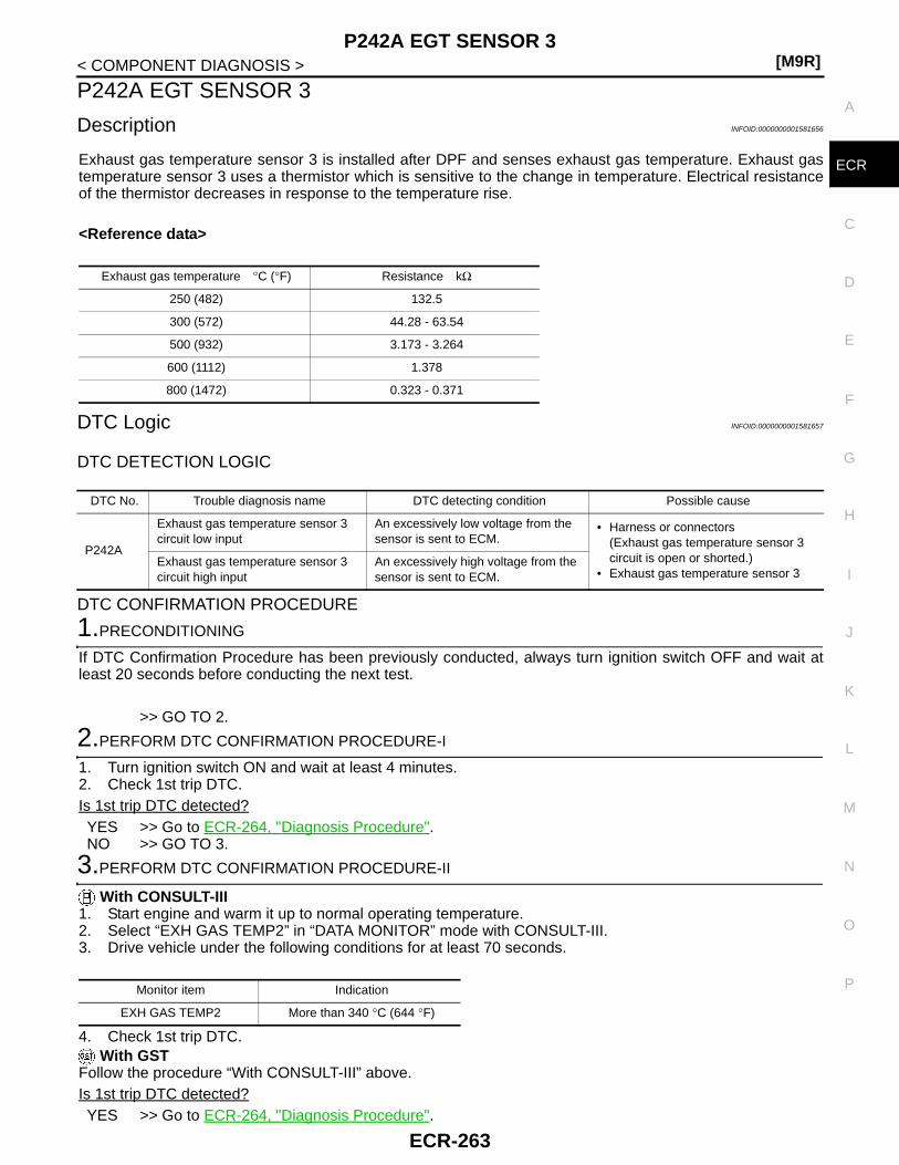
P242A EGT SENSOR 3[M9R]
C
D
E
F
G
H
I
J
K
L
M
A
CR
N
P
O
< COMPONENT DIAGNOSIS >
E
P242A EGT SENSOR 3
Description INFOID:0000000001581656
Exhaust gas temperature sensor 3 is installed after DPF and senses exhaust gas temperature. Exhaust gastemperature sensor 3 uses a thermistor which is sensitive to the change in temperature. Electrical resistanceof the thermistor decreases in response to the temperature rise.
<Reference data>
DTC Logic INFOID:0000000001581657
DTC DETECTION LOGIC
DTC CONFIRMATION PROCEDURE
1.PRECONDITIONING
If DTC Confirmation Procedure has been previously conducted, always turn ignition switch OFF and wait atleast 20 seconds before conducting the next test.
>> GO TO 2.
2.PERFORM DTC CONFIRMATION PROCEDURE-I
1. Turn ignition switch ON and wait at least 4 minutes.2. Check 1st trip DTC.Is 1st trip DTC detected?YES >> Go to ECR-264, "Diagnosis Procedure".NO >> GO TO 3.
3.PERFORM DTC CONFIRMATION PROCEDURE-II
With CONSULT-III1. Start engine and warm it up to normal operating temperature.2. Select “EXH GAS TEMP2” in “DATA MONITOR” mode with CONSULT-III.3. Drive vehicle under the following conditions for at least 70 seconds.
4. Check 1st trip DTC. With GST
Follow the procedure “With CONSULT-III” above.Is 1st trip DTC detected?YES >> Go to ECR-264, "Diagnosis Procedure".
Exhaust gas temperature °C (°F) Resistance kΩ
250 (482) 132.5
300 (572) 44.28 - 63.54
500 (932) 3.173 - 3.264
600 (1112) 1.378
800 (1472) 0.323 - 0.371
DTC No. Trouble diagnosis name DTC detecting condition Possible cause
P242A
Exhaust gas temperature sensor 3 circuit low input
An excessively low voltage from the sensor is sent to ECM.
• Harness or connectors(Exhaust gas temperature sensor 3 circuit is open or shorted.)
• Exhaust gas temperature sensor 3Exhaust gas temperature sensor 3 circuit high input
An excessively high voltage from the sensor is sent to ECM.
Monitor item Indication
EXH GAS TEMP2 More than 340 °C (644 °F)
ECR-263

[M9R]P242A EGT SENSOR 3
< COMPONENT DIAGNOSIS >NO >> INSPECTION END
Diagnosis Procedure INFOID:0000000001581658
1.CHECK GROUND CONNECTIONS
1. Turn ignition switch OFF and wait at least 20 seconds.2. Check ground connection E17. Refer to Ground inspection in GI-41, "Circuit Inspection".Is the inspection result normal?YES >> GO TO 2.NO >> Repair or replace ground connection.
2.CHECK EXHAUST GAS TEMPERATURE SENSOR 3 POWER SUPPLY CIRCUIT
1. Disconnect exhaust gas temperature sensor 3 harness connector.2. Turn ignition switch ON.3. Check the voltage between exhaust gas temperature sensor 3 harness connector and ground.
Is the inspection result normal?YES >> GO TO 4.NO >> GO TO 3.
3.DETECT MALFUNCTIONING PART
Check the following.• Harness connectors E6, F123• Harness connectors B11, E101• Harness for open or short between ECM and exhaust gas temperature sensor 3
>> Repair open circuit or short to ground or short to power in harness or connectors.
4.CHECK EXHAUST GAS TEMPERATURE SENSOR 3 GROUND CIRCUIT FOR OPEN AND SHORT
1. Turn ignition switch OFF and wait at least 20 seconds.2. Check the continuity between exhaust gas temperature sensor 3 harness connector and ECM harness
connector.
3. Also check harness for short to ground and short to power. Is the inspection result normal?YES >> GO TO 6.NO >> GO TO 5.
5.DETECT MALFUNCTIONING PART
Check the following.• Harness connectors E6, F123• Harness connectors B11, E101• Harness for open or short between ECM and exhaust gas temperature sensor 3
>> Repair open circuit or short to ground or short to power in harness or connectors.
6.CHECK EXHAUST GAS TEMPERATURE SENSOR 3
Refer to ECR-265, "Component Inspection".Is the inspection result normal?
Exhaust gas temperature sensor 3Ground Voltage
Connector Terminal
B50 1 Ground Approx. 5V
Exhaust gas temperature sensor 3 ECMContinuity
Connector Terminal Connector Terminal
B50 2 F131 23 Existed
ECR-264

P242A EGT SENSOR 3[M9R]
C
D
E
F
G
H
I
J
K
L
M
A
CR
N
P
O
< COMPONENT DIAGNOSIS >
E
YES >> GO TO 7.NO >> Replace exhaust gas temperature sensor 3.
7.CHECK INTERMITTENT INCIDENT
Refer to GI-39, "Intermittent Incident".
>> INSPECTION END
Component Inspection INFOID:0000000001581659
1.CHECK EXHAUST GAS TEMPERATURE SENSOR 3
With CONSULT-III1. Turn ignition switch ON and select “EXH GAS TEMP3” in “DATA MONITOR” mode with CONSULT-III..2. Start engine and drive vehicle at a speed of 120 km/h (75 MPH) for at least 2 minute.3. Check “EXH GAS TEMP3” indication during driving.
With GSTFollow the procedure “With CONSULT-III” above.Is the inspection result normal?YES >> INSPECTION ENDNO >> Replace exhaust gas temperature sensor 3.
Monitor item Indication
EXH GAS TEMP3 230 - 950 °C (446 - 1742 °F)
ECR-265
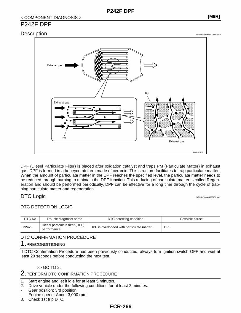
[M9R]P242F DPF
< COMPONENT DIAGNOSIS >
P242F DPF
Description INFOID:0000000001581660
DPF (Diesel Particulate Filter) is placed after oxidation catalyst and traps PM (Particulate Matter) in exhaustgas. DPF is formed in a honeycomb form made of ceramic. This structure facilitates to trap particulate matter.When the amount of particulate matter in the DPF reaches the specified level, the particulate matter needs tobe reduced through burning to maintain the DPF function. This reducing of particulate matter is called Regen-eration and should be performed periodically. DPF can be effective for a long time through the cycle of trap-ping particulate matter and regeneration.
DTC Logic INFOID:0000000001581661
DTC DETECTION LOGIC
DTC CONFIRMATION PROCEDURE
1.PRECONDITIONING
If DTC Confirmation Procedure has been previously conducted, always turn ignition switch OFF and wait atleast 20 seconds before conducting the next test.
>> GO TO 2.
2.PERFORM DTC CONFIRMATION PROCEDURE
1. Start engine and let it idle for at least 5 minutes.2. Drive vehicle under the following conditions for at least 2 minutes.- Gear position: 3rd position- Engine speed: About 3,000 rpm3. Check 1st trip DTC.
PBIB3160E
DTC No. Trouble diagnosis name DTC detecting condition Possible cause
P242FDiesel particulate filter (DPF) performance
DPF is overloaded with particulate matter. DPF
ECR-266

P242F DPF[M9R]
C
D
E
F
G
H
I
J
K
L
M
A
CR
N
P
O
< COMPONENT DIAGNOSIS >
E
Is 1st trip DTC detected?YES >> Go to ECR-267, "Diagnosis Procedure".NO >> INSPECTION END
Diagnosis Procedure INFOID:0000000001581662
1.CHECK DPF
Refer to ECR-232, "Component Inspection".OK or NGOK >> INSPECTION ENDNG >> GO TO 2.
2.REPLACE DPF
1. Replace DPF.2. Perform “DPF Data Clear”. Refer to ECR-17, "DPF DATA CLEAR : Special Repair Requirement".
>> INSPECTION END
Component Inspection INFOID:0000000001581663
1.CHECK DPF-I
Check DPF for damage.Is the inspection result normal?YES >> GO TO 2.NO >> GO TO 3.
2.CHECK DPF-II
1. Perform “Service Regeneration”. Refer to ECR-17, "SERVICE REGENERATION : Special RepairRequirement".
2. Start engine and warm it up to normal operating temperature.3. Connect CONSULT-III and select “DATA MONITOR” mode.4. Select “DIFF EXH PRES” and check the indication under the following conditions.
Is the inspection result normal?YES >> INSPECTION ENDNO >> GO TO 3.
3.REPLACE DPF
1. Replace DPF.2. Perform “DPF Data Clear”. Refer to ECR-17, "DPF DATA CLEAR : Special Repair Requirement".
>> INSPECTION END
Condition DIFF EXH PRES [mbar]
• ENGINE SPEED·: 2000 tr/min• EXH GAS TEMP2: 150 - 200°C (302 - 392°F)• EXH GAS TEMP3: 150 - 200°C (302 - 392°F)
Less than 3.0
ECR-267

[M9R]P2452 DIFFERENTIAL EXHAUST PRESSURE SENSOR
< COMPONENT DIAGNOSIS >
P2452 DIFFERENTIAL EXHAUST PRESSURE SENSOR
Description INFOID:0000000001581664
Differential exhaust pressure sensor is connected to DPF with differ-ential pressure sensor tubes (upstream and downstream). Differen-tial exhaust pressure sensor measures the difference between theexhaust pressure before and after the DPF. Differential exhaustpressure sensor converts the difference into a voltage signal. ECMreceives the signal and estimates the amount of particulate matter inDPF.
DTC Logic INFOID:0000000001581665
DTC DETECTION LOGIC
DTC CONFIRMATION PROCEDURE
1.PRECONDITIONING
If DTC Confirmation Procedure has been previously conducted, always turn ignition switch OFF and wait atleast 20 seconds before conducting the next test.
>> GO TO 2.
2.PERFORM DTC CONFIRMATION PROCEDURE
1. Turn ignition switch ON and wait at least 10 seconds.2. Check 1st trip DTC.Is 1st trip DTC detected?YES >> Go to ECR-268, "Diagnosis Procedure".NO >> INSPECTION END
Diagnosis Procedure INFOID:0000000001581666
1.CHECK GROUND CONNECTIONS
1. Turn ignition switch OFF and wait at least 20 seconds.2. Check ground connection E17. Refer to Ground inspection in GI-41, "Circuit Inspection".Is the inspection result normal?YES >> GO TO 2.NO >> Repair or replace ground connection.
2.CHECK DIFFERENTIAL EXAUST PRESSURE SENSOR POWER SUPPLY CIRCUIT
1. Disconnect differential exhaust pressure sensor harness connector.2. Turn ignition switch ON.3. Check the voltage between differential exhaust pressure sensor harness connector and ground.
PBIB3165E
DTC No. Trouble diagnosis name DTC detecting condition Possible cause
P2452Differential exhaust pressure sensor circuit
An excessively low voltage from the sensor is sent to ECM.
• Harness or connectors(Differential exhaust pressure sensor circuit is open or shorted.)
• Differential exhaust pressure sensor
An excessively high voltage from the sensor is sent to ECM.
An improper voltage is sent to ECM through sensor.
ECR-268
P2452 DIFFERENTIAL EXHAUST PRESSURE SENSOR[M9R]
C
D
E
F
G
H
I
J
K
L
M
A
CR
N
P
O
< COMPONENT DIAGNOSIS >
EIs the inspection result normal?YES >> GO TO 3.NO >> Repair open circuit or short to ground or short to power in harness or connectors.
3.CHECK DIFFERENTIAL EXAUST PRESSURE SENSOR GROUND CIRCUIT FOR OPEN AND SHORT
1. Turn ignition switch OFF and wait at least 20 seconds.2. Check the continuity between differential exhaust pressure sensor harness connector and ECM harness
connector.
3. Also check harness for short to ground and short to power. Is the inspection result normal?YES >> GO TO 4.NO >> Repair open circuit or short to ground or short to power in harness or connectors.
4.CHECK DIFFERENTIAL EXAUST PRESSURE SENSOR INPUT SIGNAL CIRCUIT FOR OPEN ANDSHORT
1. Check the continuity between differential exhaust pressure sensor harness connector and ECM harnessconnector.
2. Also check harness for short to ground and short to power. Is the inspection result normal?YES >> GO TO 5.NO >> Repair open circuit or short to ground or short to power in harness or connectors.
5.CHECK INTERMITTENT INCIDENT
Refer to GI-39, "Intermittent Incident".Is the inspection result normal?YES >> Replace differential exhaust pressure sensor.NO >> Repair or replace.
Differential exhaust pressure sensorGround Voltage
Connector Terminal
F135 3 Ground Approx. 5V
Differential exhaust pressure sensor ECMContinuity
Connector Terminal Connector Terminal
F135 2 F131 42 Existed
Differential exhaust pressure sensor ECMContinuity
Connector Terminal Connector Terminal
F135 1 F131 38 Existed
ECR-269

[M9R]P2453 DIFFERENTIAL EXHAUST PRESSURE SENSOR
< COMPONENT DIAGNOSIS >
P2453 DIFFERENTIAL EXHAUST PRESSURE SENSOR
Description INFOID:0000000001581667
Differential exhaust pressure sensor is connected to DPF with differ-ential pressure sensor tubes (upstream and downstream). Differen-tial exhaust pressure sensor measures the difference between theexhaust pressure before and after the DPF. Differential exhaustpressure sensor converts the difference into a voltage signal. ECMreceives the signal and estimates the amount of particulate matter inDPF.
DTC Logic INFOID:0000000001581668
DTC DETECTION LOGIC
DTC CONFIRMATION PROCEDURE
1.PRECONDITIONING
If DTC Confirmation Procedure has been previously conducted, always turn ignition switch OFF and wait atleast 20 seconds before conducting the next test.
>> GO TO 2.
2.PERFORM DTC CONFIRMATION PROCEDURE
1. Start engine and let it idle for at least 10 seconds.2. Check 1st trip DTC.Is 1st trip DTC detected?YES >> Go to ECR-270, "Diagnosis Procedure".NO >> INSPECTION END
Diagnosis Procedure INFOID:0000000001581669
1.CHECK DIFFERENTIAL EXHAUST PRESSURE SENSOR TUBE (UPSTREAM)
1. Remove differential exhaust pressure sensor tube (Upstream).2. Check differential exhaust pressure sensor tube (Upstream) for crack, clogging, improper connection or
disconnection.Is the inspection result normal?YES >> GO TO 2.NO >> Repair differential exhaust pressure sensor tube (Upstream).
2.CHECK INTERMITTENT INCIDENT
Refer to GI-39, "Intermittent Incident".Is the inspection result normal?YES >> Replace differential exhaust pressure sensor.NG >> Repair or replace.
PBIB3165E
DTC No. Trouble diagnosis name DTC detecting condition Possible cause
P2453Differential exhaust pressure sensor (Upstream)
Differential exhaust pressure sensor (Upstream) malfunction.
• Differential exhaust pressure sensor• Differential exhaust pressure sensor tube
(Upstream) leaks• Differential pressure sensor tube in-
stalled incorrectly
ECR-270
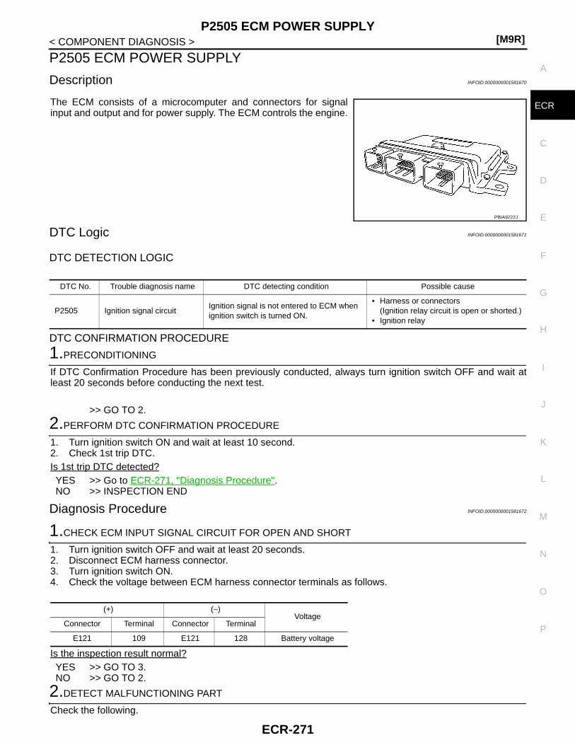
P2505 ECM POWER SUPPLY[M9R]
C
D
E
F
G
H
I
J
K
L
M
A
CR
N
P
O
< COMPONENT DIAGNOSIS >
E
P2505 ECM POWER SUPPLY
Description INFOID:0000000001581670
The ECM consists of a microcomputer and connectors for signalinput and output and for power supply. The ECM controls the engine.
DTC Logic INFOID:0000000001581671
DTC DETECTION LOGIC
DTC CONFIRMATION PROCEDURE
1.PRECONDITIONING
If DTC Confirmation Procedure has been previously conducted, always turn ignition switch OFF and wait atleast 20 seconds before conducting the next test.
>> GO TO 2.
2.PERFORM DTC CONFIRMATION PROCEDURE
1. Turn ignition switch ON and wait at least 10 second.2. Check 1st trip DTC.Is 1st trip DTC detected?YES >> Go to ECR-271, "Diagnosis Procedure".NO >> INSPECTION END
Diagnosis Procedure INFOID:0000000001581672
1.CHECK ECM INPUT SIGNAL CIRCUIT FOR OPEN AND SHORT
1. Turn ignition switch OFF and wait at least 20 seconds.2. Disconnect ECM harness connector.3. Turn ignition switch ON.4. Check the voltage between ECM harness connector terminals as follows.
Is the inspection result normal?YES >> GO TO 3.NO >> GO TO 2.
2.DETECT MALFUNCTIONING PART
Check the following.
PBIA9222J
DTC No. Trouble diagnosis name DTC detecting condition Possible cause
P2505 Ignition signal circuitIgnition signal is not entered to ECM when ignition switch is turned ON.
• Harness or connectors(Ignition relay circuit is open or shorted.)
• Ignition relay
(+) (−)Voltage
Connector Terminal Connector Terminal
E121 109 E121 128 Battery voltage
ECR-271

[M9R]P2505 ECM POWER SUPPLY
< COMPONENT DIAGNOSIS >• 10A fuse (No. 4)• IPDM E/R harness connector E15• Harness for open or short between ECM and fuse
>> Repair or replace harness or connectors.
3.CHECK INTERMITTENT INCIDENT
Refer to GI-39, "Intermittent Incident".Is the inspection result normal?YES >> GO TO 4.NO >> Repair or replace harness or connectors.
4.PERFORM DTC CONFIRMATION PROCEDURE
1. Turn ignition switch ON.2. Erase the DTC.3. Perform DTC CONFIRMATION PROCEDURE again.
See ECR-271, "DTC Logic".Is the 1st trip DTC P2505 displayed again?YES >> GO TO 5.NO >> INSPECTION END
5.REPLACE ECM
1. Replace ECM.2. Go to ECR-12, "ADDITIONAL SERVICE WHEN REPLACING CONTROL UNIT : Special Repair Require-
ment".
>> INSPECTION END
ECR-272

P2600 TC COOLING PUMP[M9R]
C
D
E
F
G
H
I
J
K
L
M
A
CR
N
P
O
< COMPONENT DIAGNOSIS >
E
P2600 TC COOLING PUMP
Description INFOID:0000000001581673
Turbocharger cooling pump circulates cooling water around the turbine bearing to prevent high oil temperaturearound it. Therefore, ECM actuates the cooling pump when the cooling water temperature exceeds the speci-fied value.
DTC Logic INFOID:0000000001581674
DTC DETECTION LOGIC
DTC CONFIRMATION PROCEDURE
1.PRECONDITIONING
If DTC Confirmation Procedure has been previously conducted, always turn ignition switch OFF and wait atleast 20 seconds before conducting the next test.
>> GO TO 2.
2.PERFORM DTC CONFIRMATION PROCEDURE-I
1. Turn ignition switch ON and wait at least 10 seconds.2. Check 1st trip DTC.Is 1st trip DTC detected?YES >> Go to ECR-273, "Diagnosis Procedure".NO >> GO TO 3.
3.PERFORM DTC CONFIRMATION PROCEDURE-II
1. Turn ignition switch OFF and wait at least 20 seconds.2. Turn ignition switch ON and wait at least 10 seconds.3. Check 1st trip DTC.Is 1st trip DTC detected?YES >> Go to ECR-273, "Diagnosis Procedure".NO >> INSPECTION END
Diagnosis Procedure INFOID:0000000001581675
1.CHECK TURBOCHARGER COOLING PUMP POWER SUPPLY CIRCUIT-I
1. Turn ignition switch OFF and wait at least 20 seconds.2. Disconnect turbocharger cooling pump relay.3. Turn ignition switch ON.4. Check the voltage between turbocharger cooling pump relay harness connector and ground.
Is the inspection result normal?
DTC No. Trouble diagnosis name DTC detecting condition Possible cause
P2600Turbocharger cooling pump circuit
An excessively low voltage from the control valve is sent to ECM. • Harness or connectors
(Turbocharger cooling pump circuit is open or shorted.)
• Turbocharger cooling pump• Turbocharger cooling pump relay
An excessively high voltage from the control valve is sent to ECM.
An improper voltage is sent to ECM through control valve.
Turbocharger cooling pump relayGround Voltage
Connector Terminal
E562
Ground Battery voltage3
ECR-273

[M9R]P2600 TC COOLING PUMP
< COMPONENT DIAGNOSIS >YES >> GO TO 3.NO >> GO TO 2.
2.DETECT MALFUNCTIONING PART
Check the following.• 20A fuse (No. 31)• Harness for open or short between turbocharger cooling pump relay and battery• Harness for open or short between turbocharger cooling pump relay and IPDM E/R
>> Repair open circuit or short to ground or short to power in harness or connectors.
3.CHECK TURBOCHARGER COOLING PUMP POWER SUPPLY CIRCUIT-II
1. Turn ignition switch OFF and wait at least 20 seconds.2. Disconnect turbocharger cooling pump harness connector.3. Check the continuity between turbocharger cooling pump harness connector and turbocharger cooling
pump relay harness connector.
4. Also check harness for short to ground and short to power. Is the inspection result normal?YES >> GO TO 5.NO >> GO TO 4.
4.DETECT MALFUNCTIONING PART
Check the following.• Harness connectors E7, F121• Harness for open or short between turbocharger cooling pump and turbocharger cooling pump relay
>> Repair open circuit or short to ground or short to power in harness or connectors.
5.CHECK TURBOCHARGER COOLING PUMP GROUND CIRCUIT FOR OPEN AND SHORT
1. Check the continuity between turbocharger cooling pump harness connector and ground.
2. Also check harness for short to ground and short to power. Is the inspection result normal?YES >> GO TO 7.NO >> GO TO 6.
6.DETECT MALFUNCTIONING PART
Check the following.• Harness connectors E7, F121• Harness for open or short between turbocharger cooling pump and ground
>> Repair open circuit or short to ground or short to power in harness or connectors.
7.CHECK TURBOCHARGER COOLING PUMP OUTPUT SIGNAL CIRCUIT FOR OPEN AND SHORT
1. Disconnect ECM harness connectors.2. Check the continuity between turbocharger cooling pump relay harness connector and ECM harness con-
nector.
Turbocharger cooling pump Turbocharge cooling pump relayContinuity
Connector Terminal Connector Terminal
F137 1 E56 5 Existed
Turbocharger cooling pumpGround Continuity
Connector Terminal
F137 2 Ground Existed
ECR-274

P2600 TC COOLING PUMP[M9R]
C
D
E
F
G
H
I
J
K
L
M
A
CR
N
P
O
< COMPONENT DIAGNOSIS >
EIs the inspection result normal?YES >> GO TO 9.NO >> GO TO 8.
8.DETECT MALFUNCTIONING PART
Check the following.• Harness connectors E7, F121• Harness for open or short between ECM and turbocharger cooling pump relay
>> Repair open circuit or short to ground or short to power in harness or connectors.
9.CHECK TURBOCHARGER COOLING PUMP RELAY
Refer to ECR-275, "Component Inspection (Turbocharger Cooling Pump Relay)".Is the inspection result normal?YES >> GO TO 10.NO >> Replace turbocharger cooling pump relay.
10.CHECK TURBOCHARGER COOLING PUMP
Refer to ECR-275, "Component Inspection (Turbocharger Cooling Pump)".Is the inspection result normal?YES >> GO TO 11.NO >> Replace turbocharger cooling pump.
11.CHECK INTERMITTENT INCIDENT
Refer to GI-39, "Intermittent Incident".
>> INSPECTION END
Component Inspection (Turbocharger Cooling Pump) INFOID:0000000001581676
1.CHECK TURBOCHARGER COOLING PUMP
1. Turn ignition switch OFF.2. Disconnect turbocharger cooling pump harness connector F137.3. Supply turbocharger cooling pump terminal with battery voltage and check operation.
Is the inspection result normal?YES >> INSPECTION ENDNO >> Replace turbocharger cooling pump.
Component Inspection (Turbocharger Cooling Pump Relay) INFOID:0000000001581677
1.CHECK TURBOCHARGER COOLING PUMP RELAYS
1. Turn ignition switch OFF.2. Remove turbocharger cooling pump relay.
Turbocharger cooling pump relay EMContinuity
Connector Terminal Connector Terminal
E56 1 F132 56 Existed
TerminalsOperation
(+) (–)
1 2 Turbocharger cooling pump operates.
ECR-275

[M9R]P2600 TC COOLING PUMP
< COMPONENT DIAGNOSIS >3. Check the continuity between turbocharger cooling pump relay
terminals under the following conditions.
Is the inspection result normal?YES >> INSPECTION ENDNO >> Replace turbocharger cooling pump relay.
Terminals Conditions Continuity
3 and 512V direct current supply between terminals 1 and 2 Existed
No current supply Not existed
PBIB0098E
ECR-276

P2A00 A/F SENSOR 1[M9R]
C
D
E
F
G
H
I
J
K
L
M
A
CR
N
P
O
< COMPONENT DIAGNOSIS >
E
P2A00 A/F SENSOR 1
Description INFOID:0000000001581678
Air fuel ratio (A/F) sensor 1 (1) is installed on the upstream of the oxi-dation catalyst. A/F sensor 1 measures the oxygen level in theexhaust gas and converts it into a voltage signal. A/F sensor 1 sendsthe signal to ECM. Based on the signal from A/F sensor 1, ECM cal-culates the air fuel mixture ratio. ECM uses the calculated ratio forthe DPF regeneration control.A heater is integrated in A/F sensor 1 to ensure the required operat-ing temperature.
DTC Logic INFOID:0000000001581679
DTC DETECTION LOGIC
Diagnosis Procedure INFOID:0000000001581680
1.CHECK GROUND CONNECTIONS
1. Turn ignition switch OFF and wait at least 20 seconds.2. Check ground connection E17. Refer to Ground inspection in GI-41, "Circuit Inspection".Is the inspection result normal?YES >> GO TO 2.NO >> Repair or replace ground connections.
2.CHECK AIR FUEL RATIO (A/F) SENSOR 1 POWER SUPPLY CIRCUIT
1. Disconnect A/F sensor 1 harness connector.2. Turn ignition switch ON.3. Check the voltage between A/F sensor 1 harness connector and ground.
OK or NGOK >> GO TO 4.NG >> GO TO 3.
3.DETECT MALFUNCTIONING PART
Check the following.• Harness connectors E7, F121• IPDM E/R connector E11• Harness for open or short between A/F sensor 1 and IPDM E/R• Harness for open or short between A/F sensor 1 and ECM
>> Repair or replace harness or connectors.
4.CHECK A/F SENSOR 1 INPUT SIGNAL CIRCUIT FOR OPEN AND SHORT
PBIB3183E
DTC No. Trouble diagnosis name DTC detecting condition Possible Cause
P2A00Air fuel ratio (A/F) sensor 1 circuit
The A/F signal computed by ECM from the air fuel ratio sensor 1 signal is out of the specified range.
• Harness or connectors(The air fuel ratio sensor 1 circuit is shorted.)
• Air fuel ratio sensor 1
A/F sensor 1Ground Voltage
Connector Terminal
F141 4 Ground Battery voltage
ECR-277
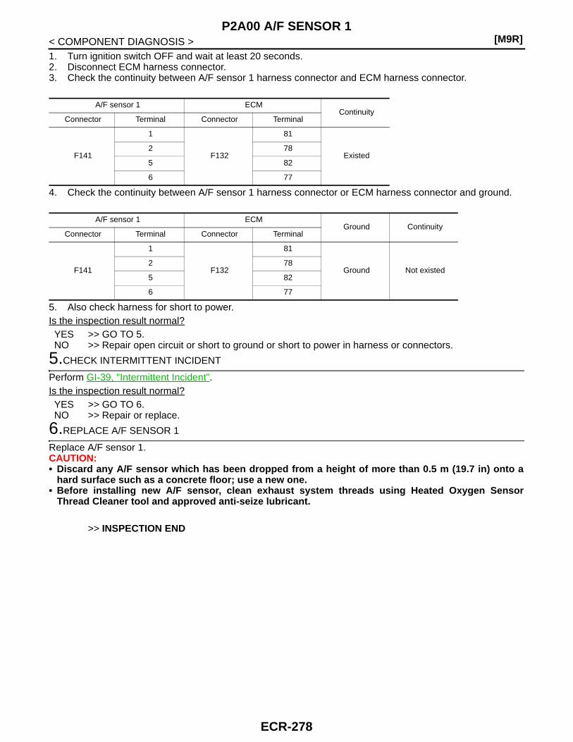
[M9R]P2A00 A/F SENSOR 1
< COMPONENT DIAGNOSIS >1. Turn ignition switch OFF and wait at least 20 seconds.2. Disconnect ECM harness connector.3. Check the continuity between A/F sensor 1 harness connector and ECM harness connector.
4. Check the continuity between A/F sensor 1 harness connector or ECM harness connector and ground.
5. Also check harness for short to power.Is the inspection result normal?YES >> GO TO 5.NO >> Repair open circuit or short to ground or short to power in harness or connectors.
5.CHECK INTERMITTENT INCIDENT
Perform GI-39, "Intermittent Incident".Is the inspection result normal?YES >> GO TO 6.NO >> Repair or replace.
6.REPLACE A/F SENSOR 1
Replace A/F sensor 1.CAUTION:• Discard any A/F sensor which has been dropped from a height of more than 0.5 m (19.7 in) onto a
hard surface such as a concrete floor; use a new one.• Before installing new A/F sensor, clean exhaust system threads using Heated Oxygen Sensor
Thread Cleaner tool and approved anti-seize lubricant.
>> INSPECTION END
A/F sensor 1 ECMContinuity
Connector Terminal Connector Terminal
F141
1
F132
81
Existed2 78
5 82
6 77
A/F sensor 1 ECMGround Continuity
Connector Terminal Connector Terminal
F141
1
F132
81
Ground Not existed2 78
5 82
6 77
ECR-278

P3031 SERVICE REGENERATION[M9R]
C
D
E
F
G
H
I
J
K
L
M
A
CR
N
P
O
< COMPONENT DIAGNOSIS >
E
P3031 SERVICE REGENERATION
Description INFOID:0000000001581681
Service regeneration is performed with CONSULT-III to reduce particulate matter in DPF.For details, refer to ECR-16, "SERVICE REGENERATION : Description".
DTC Logic INFOID:0000000001581682
DTC DETECTION LOGIC
Diagnosis Procedure INFOID:0000000001581683
1.PERFORM SERVICE REGENERATION
Refer to ECR-17, "SERVICE REGENERATION : Special Repair Requirement".
>> GO TO 2.
2.ERASE DTC
With CONSULT-III1. Turn ignition switch ON.2. Select “SELF-DIAG RESULTS” mode with CONSULT-III.3. Touch “ERASE”.
With GST1. Turn ignition switch ON.2. Select Service $04 with GST.Is DTC erased?YES >> INSPECTION ENDNO >> GO TO 3.
3.CHECK INTERMITTENT INCIDENT
Refer to GI-39, "Intermittent Incident".
>> INSPECTION END
DTC No. Trouble diagnosis name DTC detecting condition Possible cause
P3031 Service regeneration performanceService regeneration was interrupted because of extremely high exhaust gas temperature.
DPF
ECR-279

[M9R]ASCD INDICATOR
< COMPONENT DIAGNOSIS >
ASCD INDICATOR
Description INFOID:0000000001581684
ASCD indicator lamp illuminates to indicate ASCD operation status. Lamp has two indicators, CRUISE andSET, and is integrated in combination meter.CRUISE lamp illuminates when MAIN switch on ASCD steering switch is turned ON to indicated that ASCDsystem is ready for operation.SET lamp illuminates when following conditions are met. • CRUISE lamp is illuminated.• SET/COAST switch on ASCD steering switch is turned ON while vehicle speed is within the range of ASCD
setting.SET lamp remains lit during ASCD control.
Component Function Check INFOID:0000000001581685
1.ASCD INDICATOR FUNCTION
Check ASCD indicator under the following conditions.
Is the inspection result normal?YES >> INSPECTION ENDNO >> Go to ECR-280, "Diagnosis Procedure".
Diagnosis Procedure INFOID:0000000001581686
1.CHECK CAN COMMUNICATION LINE
Refer to LAN-22, "CAN System Specification Chart".OK or NGOK >> GO TO 2.NG >> Repair or replace.
2.CHECK COMBINATION METER OPERATION
Refer to MWI-27, "CONSULT-III Function (METER/M&A)".Is the inspection result normal?YES >> GO TO 3.NO >> Check combination meter circuit. Refer to MWI-7, "METER SYSTEM : System Diagram".
3.CHECK INTERMITTENT INCIDENT
Refer to GI-39, "Intermittent Incident".
>> INSPECTION END
CONDITION INDICATOR
• Ignition switch: ON• MAIN switch: Pressed at the
1st time →at the 2nd timeIlluminated → Not illuminated
• MAIN switch: ON• When vehicle speed: Between 40 km/h (25
MPH) and 144 km/h (89 MPH)
• ASCD: Operating Illuminated
• ASCD: Not operating Not illuminated
ECR-280

CLUTCH PEDAL POSITION SWITCH[M9R]
C
D
E
F
G
H
I
J
K
L
M
A
CR
N
P
O
< COMPONENT DIAGNOSIS >
E
CLUTCH PEDAL POSITION SWITCH
Description INFOID:0000000001581687
Clutch pedal position switch signal is applied to the ECM through the clutch pedal position switch when theclutch pedal is depressed.
Component Function Check INFOID:0000000001581688
1.CHECK FOR CLUTCH PEDAL POSITION SWITCH FUNCTION
1. Turn ignition switch ON.2. Check the voltage between ECM harness connector and ground.
Is the inspection result normal?YES >> INSPECTION END.NO >> Go to ECR-281, "Diagnosis Procedure".
Diagnosis Procedure INFOID:0000000001581689
1.CHECK GROUND CONNECTIONS
1. Turn ignition switch OFF and wait at least 20 seconds.2. Check ground connection E17. Refer to Ground inspection in GI-41, "Circuit Inspection".Is the inspection result normal?YES >> GO TO 2.NO >> Repair or replace ground connection.
2.CHECK CLUTCH PEDAL POSITION SWITCH GROUD CIRCUIT FOR OPEN AND SHORT
1. Disconnect clutch pedal position switch harness connector.2. Check the continuity between clutch pedal position switch harness connector and ground.
3. Also check harness for short to power. Is the inspection result normal?YES >> GO TO 3.NO >> Repair open circuit or short to power in harness or connectors.
3.CHECK CLUTCH PEDAL POSITION SWITCH INPUT SIGANL CIRCUIT FOR OPEN AND SHORT
1. Disconnect ECM harness connectors.2. Check the continuity between clutch pedal position switch harness connector and ECM harness connec-
tor.
3. Also check harness for short to ground and short to power. Is the inspection result normal?YES >> GO TO 4.
ECM GroundCondition Voltage
Connector Terminal Connector Terminal
E121108
(Clutch pedal position switch signal)
E121128
(ECM ground)Clutch pedal
Slightly depressed Battery voltage
Fully released Approx. 0V
Clutch pedal position switchGround Continuity
Connector Terminal
E111 1 E38 Existed
Clutch pedal position switch ECMContinuity
Connector Terminal Connector Terminal
E111 2 E121 108 Existed
ECR-281

[M9R]CLUTCH PEDAL POSITION SWITCH
< COMPONENT DIAGNOSIS >NO >> Repair open circuit or short to ground or short to power in harness or connectors.
4.CHECK CLUTCH PEDAL POSITION SWITCH
Refer to ECR-282, "Component Inspection".Is the inspection result normal?YES >> GO TO 5.NO >> Replace clutch pedal position switch.
5.CHECK INTERMITTENT INCIDENT
Refer to GI-39, "Intermittent Incident".
>> INSPECTION END
Component Inspection INFOID:0000000001581690
1.CHECK CLUTCH PEDAL POSITION SWITCH-I
1. Turn ignition switch OFF.2. Disconnect clutch pedal position switch harness connector.3. Check the continuity between clutch pedal position switch terminals under the following conditions.
Is the inspection result normal?YES >> INSPECTION ENDNO >> GO TO 2.
2.CHECK CLUTCH PEDAL POSITION SWITCH-II
1. Adjust clutch pedal position switch installation. Refer to CL-6, "Inspection and Adjustment".2. Check the continuity between clutch pedal position switch terminals under the following conditions.
Is the inspection result normal?YES >> INSPECTION ENDNO >> Replace clutch pedal position switch.
Terminals Condition Continuity
1 and 2 Clutch pedalFully released Existed
Slightly depressed Not existed
Terminals Condition Continuity
1 and 2 Clutch pedalFully released Existed
Slightly depressed Not existed
ECR-282

COOLING FAN[M9R]
C
D
E
F
G
H
I
J
K
L
M
A
CR
N
P
O
< COMPONENT DIAGNOSIS >
E
COOLING FAN
Description INFOID:0000000001581691
Cooling fan operates at each speed when the current flows in the cooling fan motor as follows.Refer to ECR-49, "System Diagram" for cooling fan operation.
Component Function Check INFOID:0000000001581692
1.CHECK COOLING FAN OPERATION
With CONSULT-III1. Start engine and let it idle.2. Select “COOLING FAN LOW” in “ACTIVE TEST” mode with CONSULT-III.3. Check that cooling fan operates at low speed.
With GST1. Start engine and let it idle.2. Turn air conditioner switch and blower fan switch ON.3. Check that cooling fan operates at low speed.Is the inspection result normal?YES >> GO TO 2.NO >> Check cooling fan low speed control circuit. Refer to ECR-283, "Diagnosis Procedure".
2.CHECK COOLING FAN OPERATION
With CONSULT-III1. Select “COOLING FAN HIGH” in “ACTIVE TEST” mode with CONSULT-III.2. Check that cooling fan operates at higher speed than low speed.
With GST1. Turn air conditioner switch and blower fan switch OFF.2. Turn ignition switch OFF.3. Disconnect engine coolant temperature sensor harness connector.4. Connect 150 Ω resistor to engine coolant temperature sensor harness connector.5. Check that cooling fan operates at higher speed than low speed.Is the inspection result normal?YES >> INSPECTION ENDNO >> Check cooling fan high speed control circuit. Refer to ECR-283, "Diagnosis Procedure".
Diagnosis Procedure INFOID:0000000001581693
1.INSPECTION START
Confirm the malfunctioning circuit (Low speed or high speed).Refer to ECR-283, "Component Function Check".Which circuit is malfunctioning?Low speed>>GO TO 2.High speed>>GO TO 8.
2.CHECK COOLING FAN POWER SUPPLY CIRCUIT-I
1. Turn ignition switch OFF and wait at least 20 seconds.2. Disconnect IPDM E/R harness connector E14.3. Disconnect cooling fan motor harness connector.4. Check the continuity between IPDM E/R harness connector and cooling fan motor harness connector.
5. Also check harness for short to ground and short to power.Is the inspection result normal?
IPDM E/R Cooling fan motorContinuity
Connector Terminal Connector Terminal
E14 52 E3 1 Existed
ECR-283
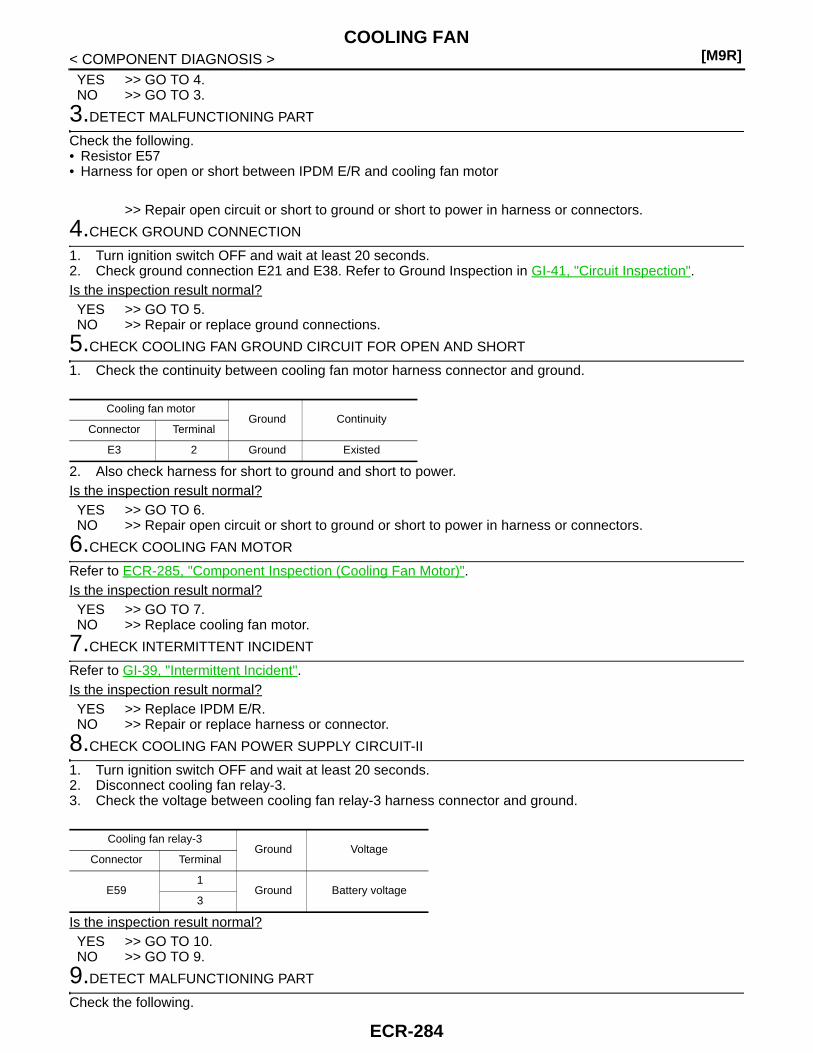
[M9R]COOLING FAN
< COMPONENT DIAGNOSIS >YES >> GO TO 4.NO >> GO TO 3.
3.DETECT MALFUNCTIONING PART
Check the following.• Resistor E57• Harness for open or short between IPDM E/R and cooling fan motor
>> Repair open circuit or short to ground or short to power in harness or connectors.
4.CHECK GROUND CONNECTION
1. Turn ignition switch OFF and wait at least 20 seconds.2. Check ground connection E21 and E38. Refer to Ground Inspection in GI-41, "Circuit Inspection".Is the inspection result normal?YES >> GO TO 5.NO >> Repair or replace ground connections.
5.CHECK COOLING FAN GROUND CIRCUIT FOR OPEN AND SHORT
1. Check the continuity between cooling fan motor harness connector and ground.
2. Also check harness for short to ground and short to power.Is the inspection result normal?YES >> GO TO 6.NO >> Repair open circuit or short to ground or short to power in harness or connectors.
6.CHECK COOLING FAN MOTOR
Refer to ECR-285, "Component Inspection (Cooling Fan Motor)".Is the inspection result normal?YES >> GO TO 7.NO >> Replace cooling fan motor.
7.CHECK INTERMITTENT INCIDENT
Refer to GI-39, "Intermittent Incident".Is the inspection result normal?YES >> Replace IPDM E/R.NO >> Repair or replace harness or connector.
8.CHECK COOLING FAN POWER SUPPLY CIRCUIT-II
1. Turn ignition switch OFF and wait at least 20 seconds.2. Disconnect cooling fan relay-3.3. Check the voltage between cooling fan relay-3 harness connector and ground.
Is the inspection result normal?YES >> GO TO 10.NO >> GO TO 9.
9.DETECT MALFUNCTIONING PART
Check the following.
Cooling fan motorGround Continuity
Connector Terminal
E3 2 Ground Existed
Cooling fan relay-3Ground Voltage
Connector Terminal
E591
Ground Battery voltage3
ECR-284

COOLING FAN[M9R]
C
D
E
F
G
H
I
J
K
L
M
A
CR
N
P
O
< COMPONENT DIAGNOSIS >
E
• 50A fusible link (Letter M)• Harness for open or short between cooling fan relay-3 and battery
>> Repair open circuit or short to ground or short to power in harness or connectors.
10.CHECK COOLING FAN POWER SUPPLY CIRCUIT-III
1. Disconnect cooling fan motor harness connector.2. Check the continuity between cooling fan relay-3 harness connector and cooling fan motor harness con-
nector.
3. Also check harness for short to ground and short to power.Is the inspection result normal?YES >> GO TO 11.NO >> Repair open circuit or short to ground or short to power in harness or connectors.
11.CHECK COOLING FAN CONTROL CIRCUIT FOR OPEN AND SHORT
1. Disconnect IPDM E/R harness connector E13.2. Check the continuity between cooling fan relay-3 harness connector and IPDM E/R harness connector.
3. Also check harness for short to ground and short to power.Is the inspection result normal?YES >> GO TO 12.NO >> Repair open circuit or short to ground or short to power in harness or connectors.
12.CHECK COOLING FAN RELAY
Refer to ECR-286, "Component Inspection (Cooling Fan Relay)".Is the inspection result normal?YES >> GO TO 13.NO >> Replace malfunctioning cooling fan relay.
13.CHECK INTERMITTENT INCIDENT
Refer to GI-39, "Intermittent Incident".Is the inspection result normal?YES >> Replace IPDM E/R.NO >> Repair or replace harness or connector.
Component Inspection (Cooling Fan Motor) INFOID:0000000001581694
1.CHECK COOLING FAN MOTOR
1. Turn ignition switch OFF.2. Disconnect cooling fan motor harness connector.3. Supply cooling fan motor terminals with battery voltage and check operation.
Is the inspection result normal?
Cooling fan relay-3 Cooling fan motorContinuity
Connector Terminal Connector Terminal
E59 2 E3 1 Existed
Cooling fan relay-3 IPDM E/RContinuity
Connector Terminal Connector Terminal
E59 4 E13 48 Existed
TerminalsOperation
(+) (−)
1 2 Cooling fan operates.
ECR-285

[M9R]COOLING FAN
< COMPONENT DIAGNOSIS >YES >> INSPECTION ENDNO >> Replace cooling fan motor.
Component Inspection (Cooling Fan Relay) INFOID:0000000001581695
1.CHECK COOLING FAN RELAY
1. Turn ignition switch OFF.2. Remove cooling fan relay-3.3. Check the continuity between cooling fan relay terminals under
the following conditions.
Is the inspection result normal?YES >> INSPECTION ENDNO >> Replace cooling fan relay.
Terminals Conditions Continuity
1 and 212V direct current supply between terminals 3 and 4 Existed
No current supply Not existed
JMBIA0452ZZ
ECR-286

ECM[M9R]
C
D
E
F
G
H
I
J
K
L
M
A
CR
N
P
O
< ECU DIAGNOSIS >
E
ECU DIAGNOSISECM
Reference Value INFOID:0000000001581696
VALUES ON THE DIAGNOSIS TOOLRemarks: Specification data are reference values. Specification data are output/input values which are detected or supplied by the ECM at the connector.
* Specification data may not be directly related to their components signals/values/operations.I.e. Adjust ignition timing with a timing light before monitoring IGN TIMING, because the monitor may show the specification data in spite of the
ignition timing not being adjusted to the specification data. this IGN TIMING monitors the data calculated by the ECM according to the signalsinput from the camshaft position sensor and other ignition timing related sensors.
Monitor item condition Values/Status
IGN SW • Ignition switch: ON → OFF → ONPRESENT → ABSENT → PRESENT
GLOW CONT• Engine: Running
(Less than 60 seconds after starting engine.)
Engine coolant: Less than 50°C (122°F) ACTIV
Engine coolant: More than 80°C (176°F) INACT
CLUTCH STATUS • Ignition switch: ONClutch pedal: Fully released NO
Clutch pedal: Slightly depressed YES
A/C RELAY• Engine: After warming up,
idle the engine
Air conditioner switch: OFF NODON
Air conditioner switch: ON DONE
ENGINE STATUS
• Ignition switch: ON +APC
• Engine: Running (Less than 60 seconds after starting engine.) RUN
• Ignition switch: OFF(A few seconds after turning ignition switch OFF)
OFF
BPP SW • Ignition switch: ONBrake pedal: Fully released RELSD
Brake pedal: Slightly depressed PRSSD
A/C APPLD• Engine: After warming up,
idle the engine
Air conditioner switch: OFF NO
Air conditioner switch: ON YES
GLOW CONT SIGNAL• Engine: Running
(Less than 60 seconds after starting engine.)
Engine coolant: Less than 50°C (122°F) PRESENT
Engine coolant: More than 80°C (176°F) ABSENT
COOLING FAN LOW• Engine: After warming up,
idle the engine• Air conditioner switch: OFF
Engine coolant: 99°C (210°F) or less ACTIV
Engine coolant: 102°C (216°F) or more INACT
COOLING FAN HIGH• Engine: After warming up,
idle the engine• Air conditioner switch: OFF
Engine coolant: 99°C (210°F) or less INACT
Engine coolant: 102°C (216°F) or more ACTIV
ECM-TCM COMM • Ignition switch: ON
ECM-TCM communication: Communicated PRESENT
ECM-TCM communication: Not communi-cated
ABSENT
A/C COMP• Engine: After warming up,
idle the engine
Air conditioner switch: OFF INACT
Air conditioner switch: ON ACTIV
NATS CODE RGST • Ignition switch: ONNATS code registration: Not registered. NO
NATS code registration: Registered. YES
CPP SW • Ignition switch: ONClutch pedal: Fully released INACT
Clutch pedal: Slightly depressed ACTIV
EGR BYPAS S/V • Engine RunningNot warm-up condition INACT
Warm-up condition ACTIV
ECR-287
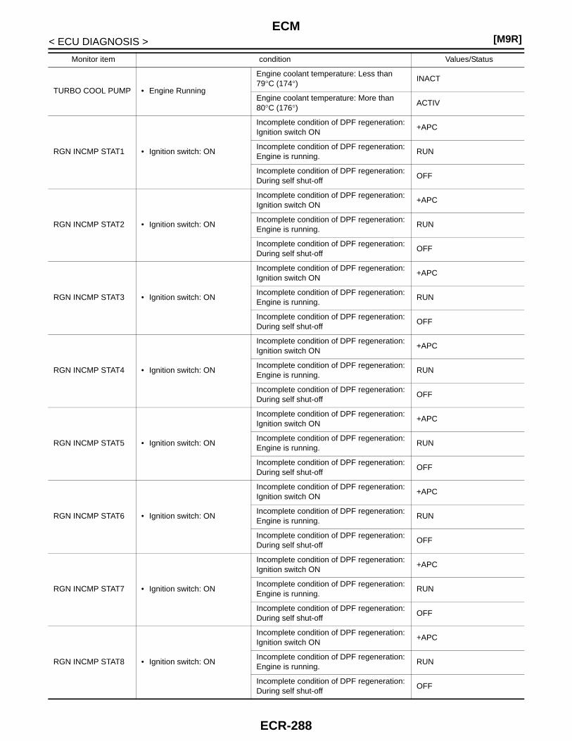
[M9R]ECM
< ECU DIAGNOSIS >
TURBO COOL PUMP • Engine Running
Engine coolant temperature: Less than 79°C (174°) INACT
Engine coolant temperature: More than 80°C (176°) ACTIV
RGN INCMP STAT1 • Ignition switch: ON
Incomplete condition of DPF regeneration: Ignition switch ON
+APC
Incomplete condition of DPF regeneration: Engine is running.
RUN
Incomplete condition of DPF regeneration: During self shut-off
OFF
RGN INCMP STAT2 • Ignition switch: ON
Incomplete condition of DPF regeneration: Ignition switch ON
+APC
Incomplete condition of DPF regeneration: Engine is running.
RUN
Incomplete condition of DPF regeneration: During self shut-off
OFF
RGN INCMP STAT3 • Ignition switch: ON
Incomplete condition of DPF regeneration: Ignition switch ON
+APC
Incomplete condition of DPF regeneration: Engine is running.
RUN
Incomplete condition of DPF regeneration: During self shut-off
OFF
RGN INCMP STAT4 • Ignition switch: ON
Incomplete condition of DPF regeneration: Ignition switch ON
+APC
Incomplete condition of DPF regeneration: Engine is running.
RUN
Incomplete condition of DPF regeneration: During self shut-off
OFF
RGN INCMP STAT5 • Ignition switch: ON
Incomplete condition of DPF regeneration: Ignition switch ON
+APC
Incomplete condition of DPF regeneration: Engine is running.
RUN
Incomplete condition of DPF regeneration: During self shut-off
OFF
RGN INCMP STAT6 • Ignition switch: ON
Incomplete condition of DPF regeneration: Ignition switch ON
+APC
Incomplete condition of DPF regeneration: Engine is running.
RUN
Incomplete condition of DPF regeneration: During self shut-off
OFF
RGN INCMP STAT7 • Ignition switch: ON
Incomplete condition of DPF regeneration: Ignition switch ON
+APC
Incomplete condition of DPF regeneration: Engine is running.
RUN
Incomplete condition of DPF regeneration: During self shut-off
OFF
RGN INCMP STAT8 • Ignition switch: ON
Incomplete condition of DPF regeneration: Ignition switch ON
+APC
Incomplete condition of DPF regeneration: Engine is running.
RUN
Incomplete condition of DPF regeneration: During self shut-off
OFF
Monitor item condition Values/Status
ECR-288

ECM[M9R]
C
D
E
F
G
H
I
J
K
L
M
A
CR
N
P
O
< ECU DIAGNOSIS >
ERGN INCMP STAT9 • Ignition switch: ON
Incomplete condition of DPF regeneration: Ignition switch ON
+APC
Incomplete condition of DPF regeneration: Engine is running.
RUN
Incomplete condition of DPF regeneration: During self shut-off
OFF
RGN INCMP STAT10 • Ignition switch: ON
Incomplete condition of DPF regeneration: Ignition switch ON
+APC
Incomplete condition of DPF regeneration: Engine is running.
RUN
Incomplete condition of DPF regeneration: During self shut-off
OFF
RGN REQ STAT1 • Ignition switch: ON
Incomplete condition of DPF regeneration: Engine stopped
STAT1
Incomplete condition of DPF regeneration: Engine starting
STAT2
Incomplete condition of DPF regeneration: Engine running
STAT3
Incomplete condition of DPF regeneration: During self shut-off
STAT4
RGN REQ STAT2 • Ignition switch: ON
Incomplete condition of DPF regeneration: Engine stopped
STAT1
Incomplete condition of DPF regeneration: Engine starting
STAT2
Incomplete condition of DPF regeneration: Engine running
STAT3
Incomplete condition of DPF regeneration: During self shut-off
STAT4
RGN REQ STAT3 • Ignition switch: ON
Incomplete condition of DPF regeneration: Engine stopped
STAT1
Incomplete condition of DPF regeneration: Engine starting
STAT2
Incomplete condition of DPF regeneration: Engine running
STAT3
Incomplete condition of DPF regeneration: During self shut-off
STAT4
RGN REQ STAT4 • Ignition switch: ON
Incomplete condition of DPF regeneration: Engine stopped
STAT1
Incomplete condition of DPF regeneration: Engine starting
STAT2
Incomplete condition of DPF regeneration: Engine running
STAT3
Incomplete condition of DPF regeneration: During self shut-off
STAT4
RGN REQ STAT5 • Ignition switch: ON
Incomplete condition of DPF regeneration: Engine stopped
STAT1
Incomplete condition of DPF regeneration: Engine starting
STAT2
Incomplete condition of DPF regeneration: Engine running
STAT3
Incomplete condition of DPF regeneration: During self shut-off
STAT4
Monitor item condition Values/Status
ECR-289

[M9R]ECM
< ECU DIAGNOSIS >
RGN REQ STAT6 • Ignition switch: ON
Incomplete condition of DPF regeneration: Engine stopped
STAT1
Incomplete condition of DPF regeneration: Engine starting
STAT2
Incomplete condition of DPF regeneration: Engine running
STAT3
Incomplete condition of DPF regeneration: During self shut-off
STAT4
RGN REQ STAT7 • Ignition switch: ON
Incomplete condition of DPF regeneration: Engine stopped
STAT1
Incomplete condition of DPF regeneration: Engine starting
STAT2
Incomplete condition of DPF regeneration: Engine running
STAT3
Incomplete condition of DPF regeneration: During self shut-off
STAT4
RGN REQ STAT8 • Ignition switch: ON
Incomplete condition of DPF regeneration: Engine stopped
STAT1
Incomplete condition of DPF regeneration: Engine starting
STAT2
Incomplete condition of DPF regeneration: Engine running
STAT3
Incomplete condition of DPF regeneration: During self shut-off
STAT4
RGN REQ STAT9 • Ignition switch: ON
Incomplete condition of DPF regeneration: Engine stopped
STAT1
Incomplete condition of DPF regeneration: Engine starting
STAT2
Incomplete condition of DPF regeneration: Engine running
STAT3
Incomplete condition of DPF regeneration: During self shut-off
STAT4
RGN REQ STAT10 • Ignition switch: ON
Incomplete condition of DPF regeneration: Engine stopped
STAT1
Incomplete condition of DPF regeneration: Engine starting
STAT2
Incomplete condition of DPF regeneration: Engine running
STAT3
Incomplete condition of DPF regeneration: During self shut-off
STAT4
EGR COOL BYPAS/V • Engine RunningNot warm-up condition INACT
Warm-up condition ACTIV
EGR/V TRG ANGLE• Ignition switch: ON Less than 1%
• Engine idle Approx. 20 - 30%
TRG RAIL PRES • Engine Running Approx. 10 bar
TRG BOOST PRES • Engine RunningIdle speed Approx Atmospheric pressure
Engine speed: 2000 rpm Approx. 10 bar (1000 mbar)
INJ VOLUME • Engine RunningIdle speed Approx. 5 - 10 mg/cp
Engine speed: 2000 rpm Approx. 5 - 10 mg/cp
ACCEL PDL POS • Ignition switch: ONAccelerator pedal: Fully released 0%
Accelerator pedal: Fully depressed 100%
Monitor item condition Values/Status
ECR-290
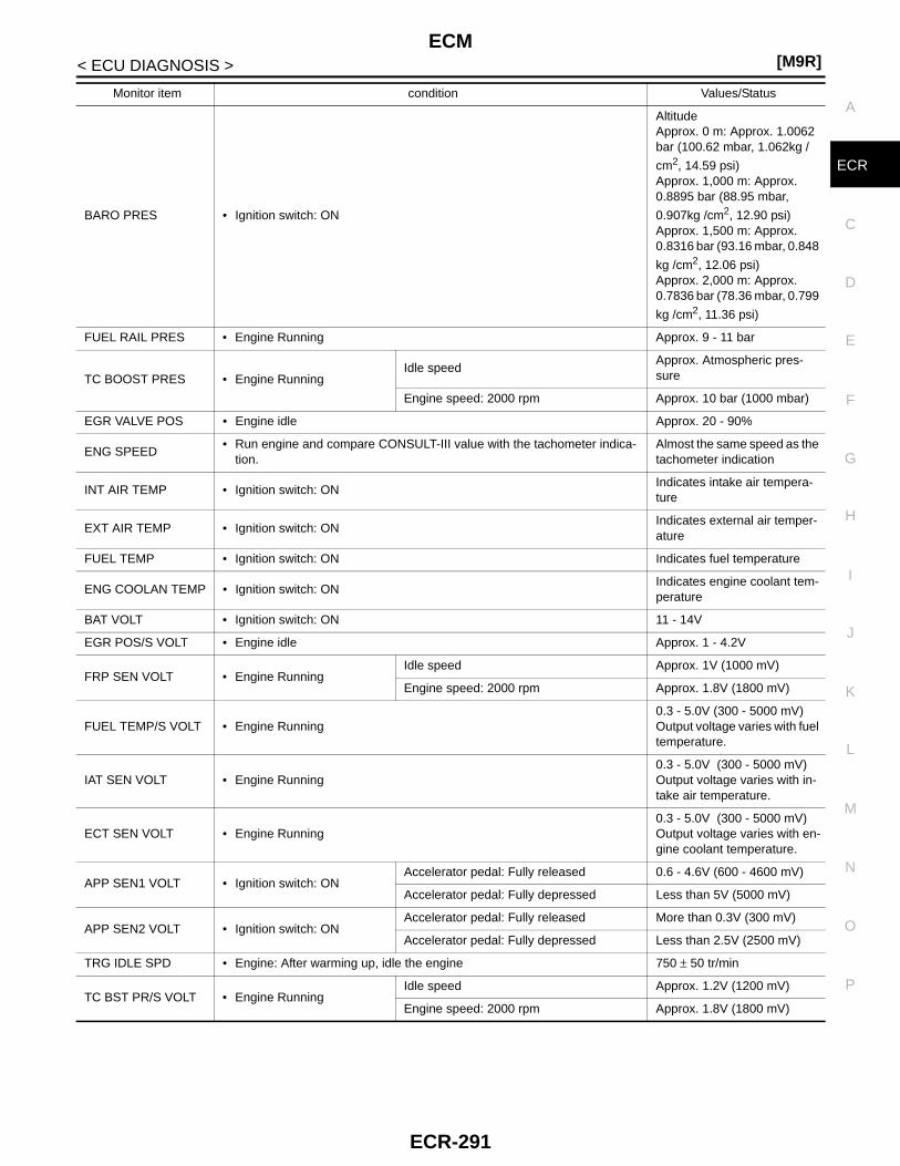
ECM[M9R]
C
D
E
F
G
H
I
J
K
L
M
A
CR
N
P
O
< ECU DIAGNOSIS >
E
BARO PRES • Ignition switch: ON
AltitudeApprox. 0 m: Approx. 1.0062 bar (100.62 mbar, 1.062kg /
cm2, 14.59 psi)Approx. 1,000 m: Approx. 0.8895 bar (88.95 mbar,
0.907kg /cm2, 12.90 psi)Approx. 1,500 m: Approx. 0.8316 bar (93.16 mbar, 0.848
kg /cm2, 12.06 psi)Approx. 2,000 m: Approx. 0.7836 bar (78.36 mbar, 0.799
kg /cm2, 11.36 psi)
FUEL RAIL PRES • Engine Running Approx. 9 - 11 bar
TC BOOST PRES • Engine RunningIdle speed
Approx. Atmospheric pres-sure
Engine speed: 2000 rpm Approx. 10 bar (1000 mbar)
EGR VALVE POS • Engine idle Approx. 20 - 90%
ENG SPEED• Run engine and compare CONSULT-III value with the tachometer indica-
tion.Almost the same speed as the tachometer indication
INT AIR TEMP • Ignition switch: ONIndicates intake air tempera-ture
EXT AIR TEMP • Ignition switch: ONIndicates external air temper-ature
FUEL TEMP • Ignition switch: ON Indicates fuel temperature
ENG COOLAN TEMP • Ignition switch: ONIndicates engine coolant tem-perature
BAT VOLT • Ignition switch: ON 11 - 14V
EGR POS/S VOLT • Engine idle Approx. 1 - 4.2V
FRP SEN VOLT • Engine RunningIdle speed Approx. 1V (1000 mV)
Engine speed: 2000 rpm Approx. 1.8V (1800 mV)
FUEL TEMP/S VOLT • Engine Running0.3 - 5.0V (300 - 5000 mV)Output voltage varies with fuel temperature.
IAT SEN VOLT • Engine Running0.3 - 5.0V (300 - 5000 mV)Output voltage varies with in-take air temperature.
ECT SEN VOLT • Engine Running0.3 - 5.0V (300 - 5000 mV)Output voltage varies with en-gine coolant temperature.
APP SEN1 VOLT • Ignition switch: ONAccelerator pedal: Fully released 0.6 - 4.6V (600 - 4600 mV)
Accelerator pedal: Fully depressed Less than 5V (5000 mV)
APP SEN2 VOLT • Ignition switch: ONAccelerator pedal: Fully released More than 0.3V (300 mV)
Accelerator pedal: Fully depressed Less than 2.5V (2500 mV)
TRG IDLE SPD • Engine: After warming up, idle the engine 750 ± 50 tr/min
TC BST PR/S VOLT • Engine RunningIdle speed Approx. 1.2V (1200 mV)
Engine speed: 2000 rpm Approx. 1.8V (1800 mV)
Monitor item condition Values/Status
ECR-291
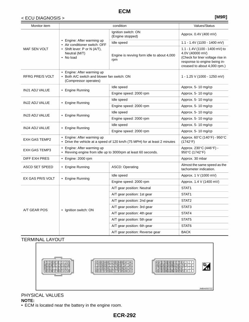
[M9R]ECM
< ECU DIAGNOSIS >
TERMINAL LAYOUT
PHYSICAL VALUESNOTE:• ECM is located near the battery in the engine room.
MAF SEN VOLT
• Engine: After warming up• Air conditioner switch: OFF• Shift lever: P or N (A/T),
Neutral (M/T)• No load
Ignition switch: ON(Engine stopped)
Approx. 0.4V (400 mV)
Idle speed 1.1 - 1.4V (1100 - 1400 mV)
Engine is revving form idle to about 4,000 rpm
1.1 - 1.4V (1100 - 1400 mV) to 4.0V (40000 mV)(Check for liner voltage rise in response to engine being in-creased to about 4,000 rpm.)
RFRG PRE/S VOLT• Engine: After warming up• Both A/C switch and blower fan switch: ON
(Compressor operates)1 - 1.25 V (1000 - 1250 mV)
INJ1 ADJ VALUE • Engine RunningIdle speed Approx. 5- 10 mg/cp
Engine speed: 2000 rpm Approx. 5- 10 mg/cp
INJ2 ADJ VALUE • Engine RunningIdle speed Approx. 5- 10 mg/cp
Engine speed: 2000 rpm Approx. 5- 10 mg/cp
INJ3 ADJ VALUE • Engine RunningIdle speed Approx. 5- 10 mg/cp
Engine speed: 2000 rpm Approx. 5- 10 mg/cp
INJ4 ADJ VALUE • Engine RunningIdle speed Approx. 5- 10 mg/cp
Engine speed: 2000 rpm Approx. 5- 10 mg/cp
EXH GAS TEMP2• Engine: After warming up• Drive the vehicle at a speed of 120 km/h (75 MPH) for at least 2 minutes
Approx. 60°C (140°F) - 950°C (1742°F)
EXH GAS TEMP3• Engine: After warming up• Revving engine from idle up to 3000rpm at least 60 seconds.
Approx. 230°C (446°F) - 950°C (1742°F)
DIFF EXH PRES • Engine: 2000 rpm Approx. 30 mbar
ASCD SET SPEED • Engine Running ASCD: OperatingAlmost the same speed as the tachometer indication.
EX GAS PR/S VOLT • Engine RunningIdle speed Approx. 1 V (1000 mV)
Engine speed: 2000 rpm Approx. 1.4 V (1400 mV)
A/T GEAR POS • Ignition switch: ON
A/T gear position: Neutral STAT1
A/T gear position: 1st gear STAT1
A/T gear position: 2nd gear STAT2
A/T gear position: 3rd gear STAT3
A/T gear position: 4th gear STAT4
A/T gear position: 5th gear STAT5
A/T gear position: 6th gear STAT6
A/T gear position: Reverse gear BACK
Monitor item condition Values/Status
JMBIA0557ZZ
ECR-292
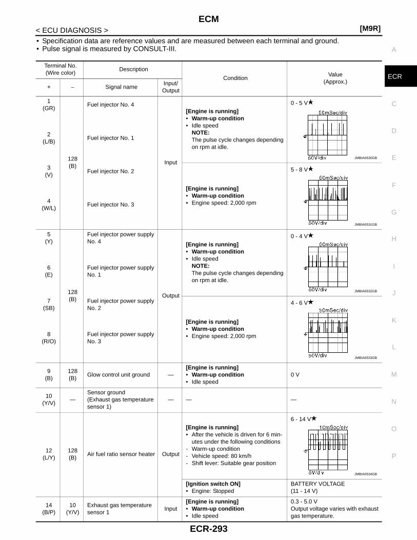
ECM[M9R]
C
D
E
F
G
H
I
J
K
L
M
A
CR
N
P
O
< ECU DIAGNOSIS >
E
• Specification data are reference values and are measured between each terminal and ground.• Pulse signal is measured by CONSULT-III.
Terminal No.(Wire color)
Description
ConditionValue
(Approx.)+ − Signal name
Input/Output
1(GR)
128(B)
Fuel injector No. 4
Input
[Engine is running]• Warm-up condition• Idle speed
NOTE:The pulse cycle changes depending on rpm at idle.
0 - 5 V
2(L/B)
Fuel injector No. 1
3(V)
Fuel injector No. 2
[Engine is running]• Warm-up condition• Engine speed: 2,000 rpm
5 - 8 V
4(W/L)
Fuel injector No. 3
5(Y)
128(B)
Fuel injector power supply No. 4
Output
[Engine is running]• Warm-up condition • Idle speed
NOTE:The pulse cycle changes depending on rpm at idle.
0 - 4 V
6(E)
Fuel injector power supply No. 1
7(SB)
Fuel injector power supply No. 2
[Engine is running]• Warm-up condition• Engine speed: 2,000 rpm
4 - 6 V
8(R/O)
Fuel injector power supply No. 3
9(B)
128(B)
Glow control unit ground —[Engine is running]• Warm-up condition• Idle speed
0 V
10(Y/V)
—Sensor ground(Exhaust gas temperature sensor 1)
— — —
12(L/Y)
128(B)
Air fuel ratio sensor heater Output
[Engine is running] • After the vehicle is driven for 6 min-
utes under the following conditions- Warm-up condition- Vehicle speed: 80 km/h- Shift lever: Suitable gear position
6 - 14 V
[Ignition switch ON]• Engine: Stopped
BATTERY VOLTAGE(11 - 14 V)
14(B/P)
10(Y/V)
Exhaust gas temperature sensor 1
Input[Engine is running] • Warm-up condition• Idle speed
0.3 - 5.0 VOutput voltage varies with exhaust gas temperature.
JMBIA0530GB
JMBIA0531GB
JMBIA0532GB
JMBIA0533GB
JMBIA0534GB
ECR-293

[M9R]ECM
< ECU DIAGNOSIS >
16(Y/R)
—Sensor ground(Exhaust gas pressure sensor)
— — —
17(G)
—Sensor ground(Turbocharger boost sen-sor)
— — —
18(O)
17(G)
Turbocharger boost sensor Input
[Engine is running] • Warm-up condition• Idle speed
1.2 V
[Engine is running] • Warm-up condition• Engine speed: 2,000 rpm
1.3 V
19(P/L)
23(G/B)
Exhaust gas temperature sensor 3
Input[Engine is running] • Warm-up condition• Idle speed
0.3 - 5.0 VOutput voltage varies with exhaust gas temperature.
20(W/R)
16(Y/R)
Exhaust gas pressure sen-sor
Input
[Engine is running] • Warm-up condition• Idle speed
1 V
[Engine is running] • Warm-up condition• Engine speed: 2,000 rpm
1.4 V
21(V)
17(G)
Sensor power supply(Turbocharger boost sen-sor)
— [Ignition switch: ON] 5 V
22(L/G)
—Sensor ground(Fuel temperature sensor)
— — —
23(G/B)
—Sensor ground(Exhaust gas temperature sensor 3)
— — —
24(Y/B)
—Sensor ground(Engine coolant tempera-ture sensor)
— — —
25(L)
16(Y/R)
Sensor power supply(Exhaust gas pressure sensor)
— [Ignition switch: ON] 5 V
26(P)
22(L/G)
Fuel temperature sensor Input[Engine is running]• Warm-up condition
0.3 - 5.0 VOutput voltage varies with fuel tem-perature.
27(GR)
39(GR/
B)
Exhaust gas temperature sensor 2
Input[Engine is running] • Warm-up condition• Idle speed
0.3 - 5.0 VOutput voltage varies with exhaust gas temperature.
28(GR/L)
24(Y/B)
Engine coolant tempera-ture sensor
Input[Engine is running]• Warm-up condition
0.3 - 5.0 VOutput voltage varies with engine coolant temperature.
29(W)
34(L)
Sensor power supply(Fuel rail pressure sensor)
— [Ignition switch: ON] 5 V
30(B)
34(L)
Fuel rail pressure sensor Input
[Engine is running] • Warm-up condition• Idle speed
1 V
[Engine is running]• Warm-up condition• Engine speed: 2,000 rpm
1.8 V
Terminal No.(Wire color)
Description
ConditionValue
(Approx.)+ − Signal name
Input/Output
ECR-294
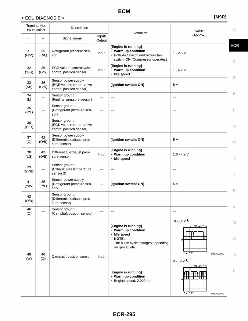
ECM[M9R]
C
D
E
F
G
H
I
J
K
L
M
A
CR
N
P
O
< ECU DIAGNOSIS >
E31
(G/P)35
(R/L)Refrigerant pressure sen-sor
Input
[Engine is running]• Warm-up condition• Both A/C switch and blower fan
switch: ON (Compressor operates)
1 - 2.5 V
32(Y/G)
36(G/R)
EGR volume control valve control position sensor
Input[Engine is running]• Warm-up condition• Idle speed
1 - 4.2 V
33(SB)
36(G/R)
Sensor power supply(EGR volume control valve control position sensor)
— [Ignition switch: ON] 5 V
34(L)
—Sensor ground(Fuel rail pressure sensor)
— — —
35(R/L)
—Sensor ground(Refrigerant pressure sen-sor)
— — —
36(G/R)
—Sensor ground(EGR volume control valve control position sensor)
— — —
37(O)
42(O/B)
Sensor power supply(Differential exhaust pres-sure sensor)
— [Ignition switch: ON] 5 V
38(LG)
42(O/B)
Differential exhaust pres-sure sensor
Input[Engine is running]• Warm-up condition• Idle speed
1.6 - 4.9 V
39(GR/B)
—Sensor ground(Exhaust gas temperature sensor 2)
— — —
41(Y/W)
35(P/L)
Sensor power supply(Refrigerant pressure sen-sor)
— [Ignition switch: ON] 5 V
42(O/B)
—Sensor ground(Differential exhaust pres-sure sensor)
— — —
46(O)
—Sensor ground(Camshaft position sensor)
— — —
48(W)
46(O)
Camshaft position sensor Input
[Engine is running]• Warm-up condition• Idle speed
NOTE:The pulse cycle changes depending on rpm at idle.
0 - 14 V
[Engine is running]• Warm-up condition• Engine speed: 2,000 rpm
0 - 14 V
Terminal No.(Wire color)
Description
ConditionValue
(Approx.)+ − Signal name
Input/Output
JMBIA0535GB
JMBIA0536GB
ECR-295
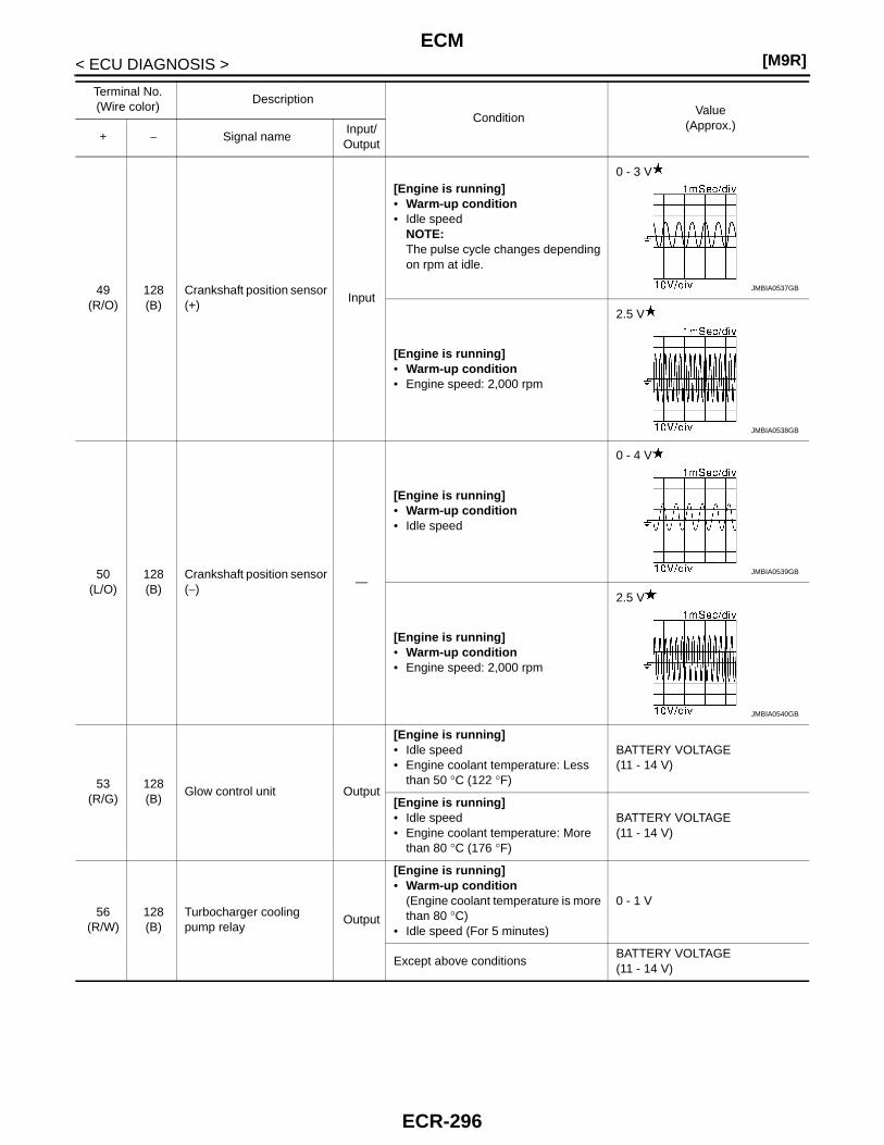
[M9R]ECM
< ECU DIAGNOSIS >
49(R/O)
128(B)
Crankshaft position sensor (+)
Input
[Engine is running]• Warm-up condition• Idle speed
NOTE:The pulse cycle changes depending on rpm at idle.
0 - 3 V
[Engine is running]• Warm-up condition• Engine speed: 2,000 rpm
2.5 V
50(L/O)
128(B)
Crankshaft position sensor (−)
—
[Engine is running]• Warm-up condition• Idle speed
0 - 4 V
[Engine is running]• Warm-up condition• Engine speed: 2,000 rpm
2.5 V
53(R/G)
128(B)
Glow control unit Output
[Engine is running]• Idle speed• Engine coolant temperature: Less
than 50 °C (122 °F)
BATTERY VOLTAGE(11 - 14 V)
[Engine is running]• Idle speed• Engine coolant temperature: More
than 80 °C (176 °F)
BATTERY VOLTAGE(11 - 14 V)
56(R/W)
128(B)
Turbocharger cooling pump relay
Output
[Engine is running]• Warm-up condition
(Engine coolant temperature is more than 80 °C)
• Idle speed (For 5 minutes)
0 - 1 V
Except above conditionsBATTERY VOLTAGE(11 - 14 V)
Terminal No.(Wire color)
Description
ConditionValue
(Approx.)+ − Signal name
Input/Output
JMBIA0537GB
JMBIA0538GB
JMBIA0539GB
JMBIA0540GB
ECR-296
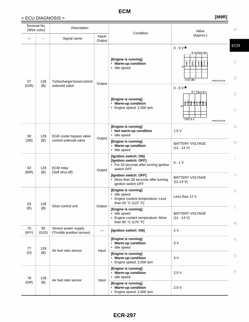
ECM[M9R]
C
D
E
F
G
H
I
J
K
L
M
A
CR
N
P
O
< ECU DIAGNOSIS >
E
57(G/R)
128(B)
Turbocharger boost control solenoid valve
Output
[Engine is running]• Warm-up condition• Idle speed
0 - 5 V
[Engine is running]• Warm-up condition• Engine speed: 2,000 rpm
0 - 5 V
59(SB)
128(B)
EGR cooler bypass valve control solenoid valve
Output
[Engine is running]• Not warm-up condition• Idle speed
1.5 V
[Engine is running]• Warm-up condition• Idle speed
BATTERY VOLTAGE(11 - 14 V)
62(B/R)
128(B)
ECM relay(Self shut-off)
Output
[Ignition switch: ON][Ignition switch: OFF]• For 20 seconds after turning ignition
switch OFF
0 - 1 V
[Ignition switch: OFF]• More than 20 seconds after turning
ignition switch OFF
BATTERY VOLTAGE(11-14 V)
63(R)
128(B)
Glow control unit Output
[Engine is running]• Idle speed• Engine coolant temperature: Less
than 50 °C (122 °F)
Less than 12 V
[Engine is running]• Idle speed• Engine coolant temperature: More
than 80 °C (176 °F)
BATTERY VOLTAGE(11 - 14 V)
75(R/Y)
85(G/O)
Sensor power supply(Throttle position sensor)
— [Ignition switch: ON] 5 V
77(O)
128(B)
Air fuel ratio sensor Input
[Engine is running] • Warm-up condition• Idle speed
3 V
[Engine is running]• Warm-up condition• Engine speed: 2,000 rpm
3 V
78(GR)
128(B)
Air fuel ratio sensor Input
[Engine is running] • Warm-up condition• Idle speed
2.5 V
[Engine is running]• Warm-up condition• Engine speed: 2,000 rpm
2.5 V
Terminal No.(Wire color)
Description
ConditionValue
(Approx.)+ − Signal name
Input/Output
JMBIA0541GB
JMBIA0542GB
ECR-297

[M9R]ECM
< ECU DIAGNOSIS >
80(L)
87(B)
Mass air flow sensor Input
[Ignition switch: ON] • Engine stopped
0.4 V
[Engine is running] • Warm-up condition• Idle speed
1.1 - 1.4 V
[Engine is running]• Warm-up condition• Engine is revving from idle to about
4,000 rpm
1.1 - 1.4 V to 4.0 V(Check for linear voltage rise in re-sponse to engine being increased to about 4,000 rpm.)
81(SB)
128(B)
Air fuel ratio sensor Input
[Engine is running] • Warm-up condition• Idle speed
3.1 V
[Engine is running]• Warm-up condition• Engine speed: 2,000 rpm
3.1 V
82(V)
128(B)
Air fuel ratio sensor Input
[Engine is running] • Warm-up condition• Idle speed
3.2 V
[Engine is running]• Warm-up condition• Engine speed: 2,000 rpm
3.2 V
83(GR/L)
85(G/O)
Throttle position sensor Input
[Ignition switch: OFF]• For 20 seconds after turning ignition
switch OFF
0 - 5 VOutput voltage fluctuates between 0 V and 5 V.
[Ignition switch: OFF]• More than 20 seconds after turning
ignition switch OFF0.7 V
84(W)
87(B)
Intake air temperature sen-sor
Input[Engine is running]• Warm-up condition
0.3 - 5.0 VOutput voltage varies with intake air temperature.
85(G/O)
—Sensor ground(Throttle position sensor)
— — —
87(B)
—
Sensor ground(Mass air flow sensor/ In-take air temperature sen-sor)
— — —
89(BR)
128(B)
Fuel pump Output
[Engine is running]• Warm-up condition• Idle speed
11 - 14 V
[Engine is running]• Warm-up condition• Engine speed: 2,000 rpm
8 - 10 V
Terminal No.(Wire color)
Description
ConditionValue
(Approx.)+ − Signal name
Input/Output
JMBIA0543GB
JMBIA0544GB
ECR-298
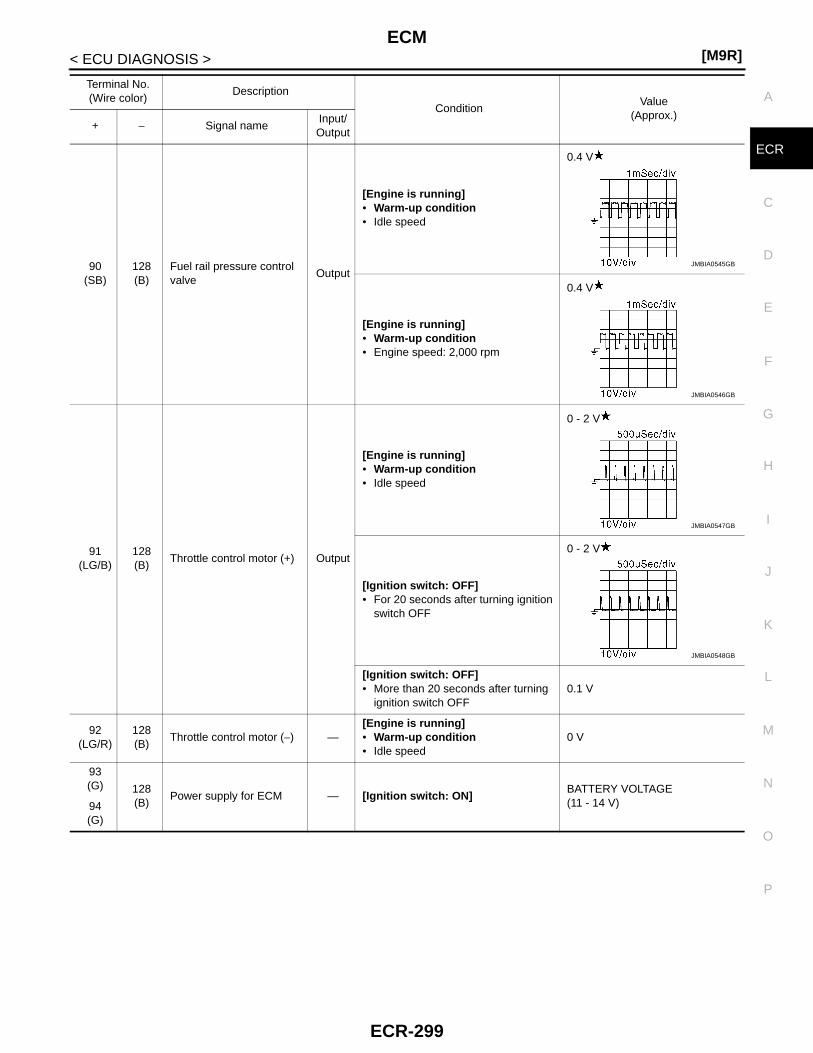
ECM[M9R]
C
D
E
F
G
H
I
J
K
L
M
A
CR
N
P
O
< ECU DIAGNOSIS >
E
90(SB)
128(B)
Fuel rail pressure control valve
Output
[Engine is running]• Warm-up condition• Idle speed
0.4 V
[Engine is running]• Warm-up condition• Engine speed: 2,000 rpm
0.4 V
91(LG/B)
128(B)
Throttle control motor (+) Output
[Engine is running]• Warm-up condition• Idle speed
0 - 2 V
[Ignition switch: OFF]• For 20 seconds after turning ignition
switch OFF
0 - 2 V
[Ignition switch: OFF]• More than 20 seconds after turning
ignition switch OFF0.1 V
92(LG/R)
128(B)
Throttle control motor (−) —[Engine is running]• Warm-up condition• Idle speed
0 V
93(G) 128
(B)Power supply for ECM — [Ignition switch: ON]
BATTERY VOLTAGE(11 - 14 V)94
(G)
Terminal No.(Wire color)
Description
ConditionValue
(Approx.)+ − Signal name
Input/Output
JMBIA0545GB
JMBIA0546GB
JMBIA0547GB
JMBIA0548GB
ECR-299

[M9R]ECM
< ECU DIAGNOSIS >
95(BR/W)
128(B)
EGR volume control valve(DC motor)
Output
[Ignition switch: OFF]• For 20 seconds after the following
conditions are met and ignition switch is turned OFF.
- Warm-up condition- Start engine and let it idle for 3 min-
utes.
0 - 1 V
[Engine is running]• Warm-up condition• Idle speed
NOTE:The duty cycle changes depending on EGR volume control valve opera-tion.
0 - 5 V
96(L/W)
128(B)
EGR volume control valve(DC motor)
Output
[Ignition switch: ON]• For 3 seconds after ignition switch is
turned ON
0 - 1 V
[Ignition switch: ON]• More than 3 seconds after ignition
switch is turned ON
0 - 1 V
[Engine is running]• Warm-up condition• Idle speed
NOTE:The duty cycle changes depending on EGR volume control valve opera-tion.
0 - 5 V
99(P)
— CAN signal (low) — — —
100(L)
— CAN signal (high) — — —
104(O)
128(B)
Data link connector —[Ignition switch: ON]• GST: Disconnected
BATTERY VALTAGE(11 - 14 V)
108(G)
128(B)
Clutch pedal position switch
Input
[Ignition switch: ON]• Clutch pedal: Slightly depressed
0 V
[Ignition switch: ON]• Clutch pedal: Fully released
BATTERY VOLTAGE(11 - 14 V)
Terminal No.(Wire color)
Description
ConditionValue
(Approx.)+ − Signal name
Input/Output
JMBIA0549GB
JMBIA0550GB
JMBIA0551GB
JMBIA0552GB
JMBIA0553GB
ECR-300
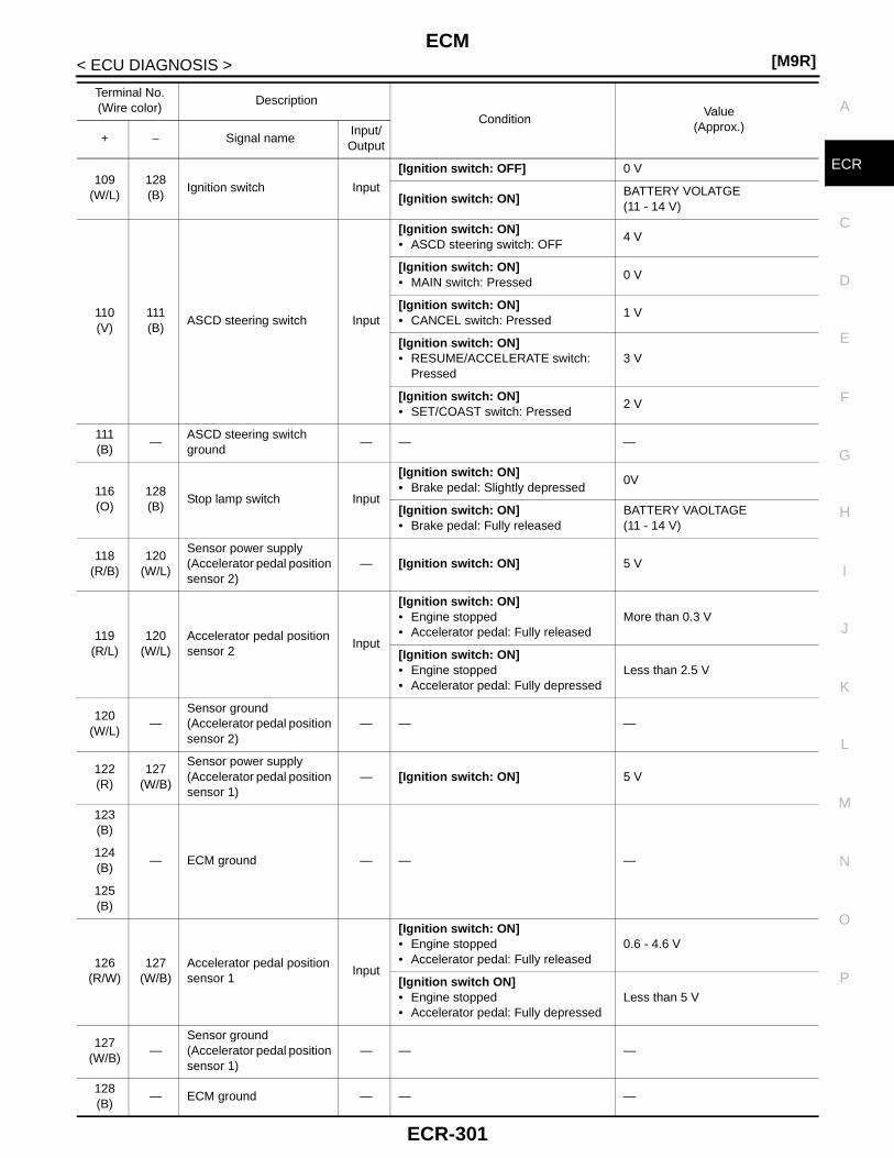
ECM[M9R]
C
D
E
F
G
H
I
J
K
L
M
A
CR
N
P
O
< ECU DIAGNOSIS >
E109
(W/L)128(B)
Ignition switch Input
[Ignition switch: OFF] 0 V
[Ignition switch: ON]BATTERY VOLATGE(11 - 14 V)
110(V)
111(B)
ASCD steering switch Input
[Ignition switch: ON]• ASCD steering switch: OFF
4 V
[Ignition switch: ON]• MAIN switch: Pressed
0 V
[Ignition switch: ON]• CANCEL switch: Pressed
1 V
[Ignition switch: ON]• RESUME/ACCELERATE switch:
Pressed3 V
[Ignition switch: ON]• SET/COAST switch: Pressed
2 V
111(B)
—ASCD steering switch ground
— — —
116(O)
128(B)
Stop lamp switch Input
[Ignition switch: ON]• Brake pedal: Slightly depressed
0V
[Ignition switch: ON]• Brake pedal: Fully released
BATTERY VAOLTAGE(11 - 14 V)
118(R/B)
120(W/L)
Sensor power supply(Accelerator pedal position sensor 2)
— [Ignition switch: ON] 5 V
119(R/L)
120(W/L)
Accelerator pedal position sensor 2
Input
[Ignition switch: ON]• Engine stopped• Accelerator pedal: Fully released
More than 0.3 V
[Ignition switch: ON]• Engine stopped• Accelerator pedal: Fully depressed
Less than 2.5 V
120(W/L)
—Sensor ground(Accelerator pedal position sensor 2)
— — —
122(R)
127(W/B)
Sensor power supply(Accelerator pedal position sensor 1)
— [Ignition switch: ON] 5 V
123(B)
— ECM ground — — —124(B)
125(B)
126(R/W)
127(W/B)
Accelerator pedal position sensor 1
Input
[Ignition switch: ON]• Engine stopped• Accelerator pedal: Fully released
0.6 - 4.6 V
[Ignition switch ON]• Engine stopped• Accelerator pedal: Fully depressed
Less than 5 V
127(W/B)
—Sensor ground(Accelerator pedal position sensor 1)
— — —
128(B)
— ECM ground — — —
Terminal No.(Wire color)
Description
ConditionValue
(Approx.)+ − Signal name
Input/Output
ECR-301
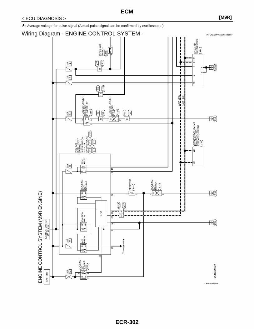
[M9R]ECM
< ECU DIAGNOSIS >
: Average voltage for pulse signal (Actual pulse signal can be confirmed by oscilloscope.)
Wiring Diagram - ENGINE CONTROL SYSTEM - INFOID:0000000001581697
JCBWA0314GB
ECR-302

ECM[M9R]
C
D
E
F
G
H
I
J
K
L
M
A
CR
N
P
O
< ECU DIAGNOSIS >
E
JCBWA0315GB
ECR-303

[M9R]ECM
< ECU DIAGNOSIS >
JCBWA0316GB
ECR-304
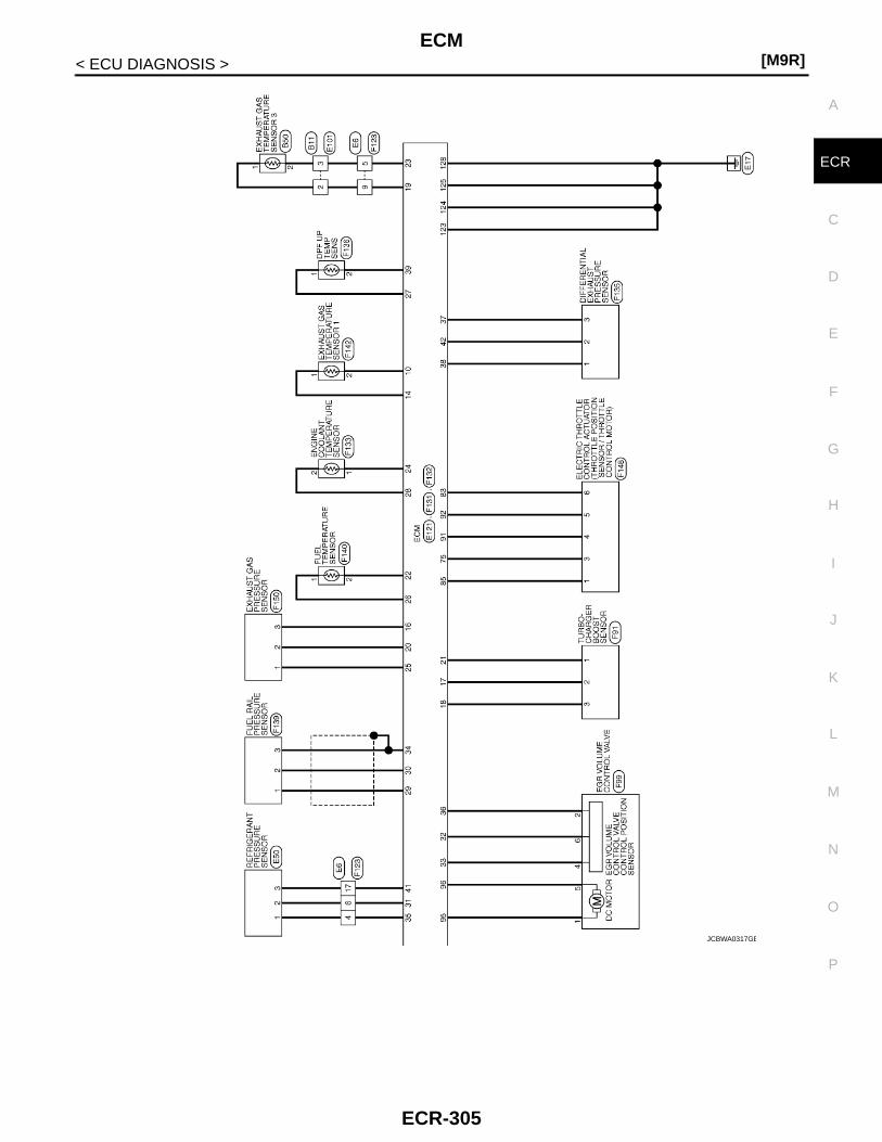
ECM[M9R]
C
D
E
F
G
H
I
J
K
L
M
A
CR
N
P
O
< ECU DIAGNOSIS >
E
JCBWA0317GB
ECR-305

[M9R]ECM
< ECU DIAGNOSIS >
JCBWA0318GB
ECR-306

ECM[M9R]
C
D
E
F
G
H
I
J
K
L
M
A
CR
N
P
O
< ECU DIAGNOSIS >
E
JCBWA0319GB
ECR-307

[M9R]ECM
< ECU DIAGNOSIS >
JCBWA0320GB
ECR-308

ECM[M9R]
C
D
E
F
G
H
I
J
K
L
M
A
CR
N
P
O
< ECU DIAGNOSIS >
E
JCBWA0321GB
ECR-309

[M9R]ECM
< ECU DIAGNOSIS >
JCBWA0322GB
ECR-310

ECM[M9R]
C
D
E
F
G
H
I
J
K
L
M
A
CR
N
P
O
< ECU DIAGNOSIS >
E
JCBWA0323GB
ECR-311

[M9R]ECM
< ECU DIAGNOSIS >
JCBWA0324GB
ECR-312
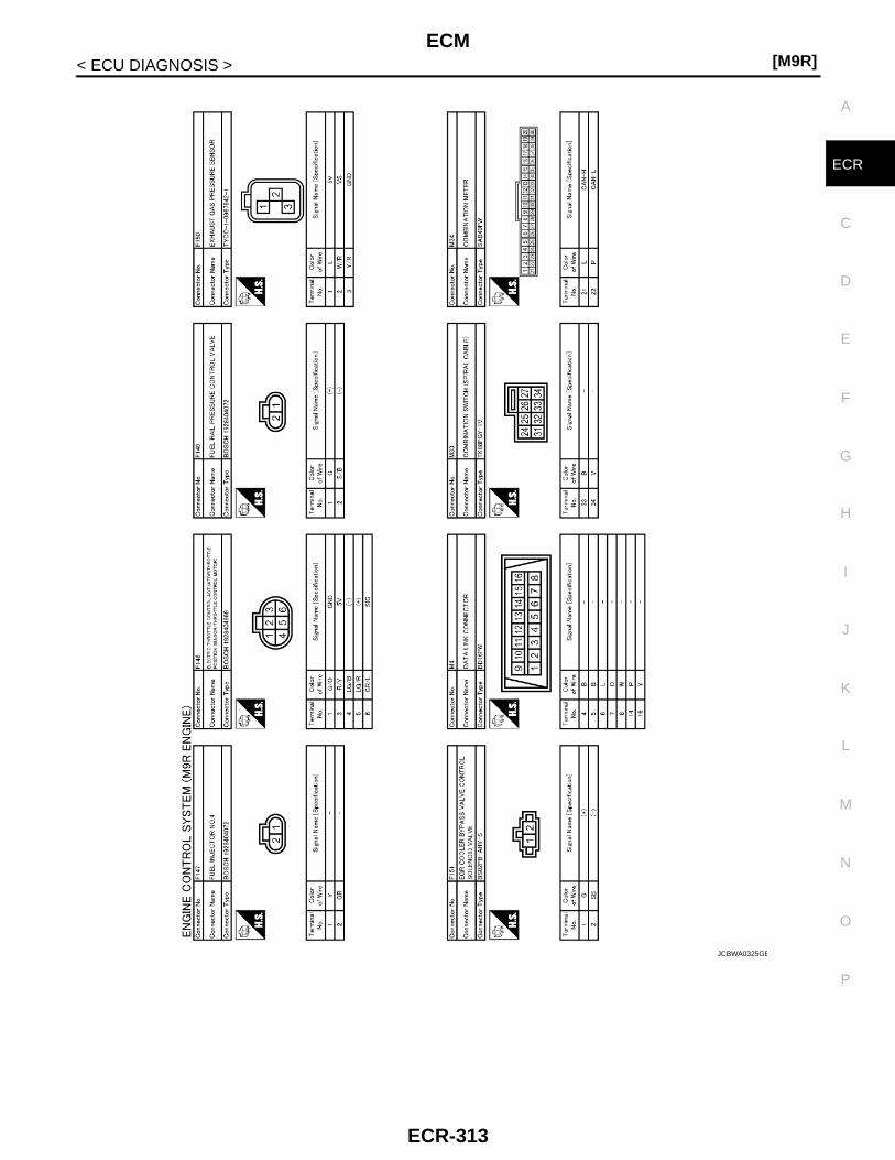
ECM[M9R]
C
D
E
F
G
H
I
J
K
L
M
A
CR
N
P
O
< ECU DIAGNOSIS >
E
JCBWA0325GB
ECR-313

[M9R]ECM
< ECU DIAGNOSIS >
Fail Safe INFOID:0000000001581698
JCBWA0347GB
DTC No. Detected items Engine operating condition in fail-safe mode
P2002 Particulate matter over accumulation Engine speed will not rise more than 2,000 rpm due to the fuel cut.
ECR-314

ECM[M9R]
C
D
E
F
G
H
I
J
K
L
M
A
CR
N
P
O
< ECU DIAGNOSIS >
E
DTC Inspection Priority Chart INFOID:0000000001581699
If some DTCs are displayed at the same time, perform inspections one by one based on the following prioritychart.
DTC Index INFOID:0000000001581700
X: Applicable —: Not applicable
Priority Detected items (DTC)
1 • U1000 CAN communication line• P0016 Crankshaft position - camshaft position correlation• P0100 Mass air flow sensor• P0110 Intake air temperature sensor• P0115 Engine coolant temperature sensor• P0120 Throttle position sensor• P0130 P0131 P0133 P0134 P2231 P2A00 Air fuel ratio (A/F) sensor 1• P0135 Air fuel ratio (A/F) sensor 1 heater• P0180 Fuel temperature sensor• P0190 P2293 Fuel rail pressure sensor• P0225 P2120 Accelerator pedal position sensor• P0235 Turbocharger boost sensor • P0335 Crankshaft position sensor• P0340 Camshaft position sensor• P0409 EGR volume control valve control position sensor• P0470 Exhaust gas pressure sensor• P0500 Vehicle speed sensor• P0530 Refrigerant pressure sensor• P0544 Exhaust gas temperature sensor 1• P0560 Battery voltage• P0606 P060B P062B P062F P1607 ECM• P0611 Fuel injector adjustment value• P0641 P0651 P0697 Sensor power supply• P1610 - P1616 NATS• P2031 Exhaust gas temperature sensor 2• P2080 P242A Exhaust gas temperature sensor 3• P2226 Barometric pressure sensor• P2299 Accelerator pedal - brake pedal position inconsistency• P2452 P2453 Differential exhaust gas pressure sensor
2 • P0045 Turbocharger boost control solenoid valve• P0089 P2294 Fuel rail pressure control valve• P0090 Fuel pump• P0200 P0201 - P0204 P0263 P0266 P0269 P0272 P1201 - P1204 P2146 P2149 Fuel injector• P0380 P0670 Glow control system• P0487 P0488 EGR volume control valve• P0571 Brake pedal position switch• P0685 ECM relay• P2100 P2101 Electric throttle control actuator• P2425 EGR cooler bypass valve control solenoid valve• P2505 Ignition relay• P2600 Turbocharger cooling pump
3 • P0297 P3031 Service regeneration• P0300 - P0304 Misfire• P0564 P0575 ASCD steering switch• P1435 P1436 DPF regeneration• P2002 P242F DPF• P2263 Turbocharger system
DTC*Items
(CONSULT-III screen terms) Trip MI lighting up Reference page
U1000 CAN COMM CIRCUIT 3 – ECR-114
P0016 CMP/CKP RELATION 3 – ECR-115
P0045 TC BOOST SOL/V 3 × ECR-117
ECR-315

[M9R]ECM
< ECU DIAGNOSIS >
P0089 FUEL PUMP 3 × ECR-119
P0090 FUEL PUMP 3 × ECR-121
P0100 MAF SENSOR 3 × ECR-123
P0101 MAF SENSOR 3 × ECR-126
P0110 IAT SENSOR 3 × ECR-130
P0115 ECT SENSOR 3 × ECR-132
P0120 TP SENSOR 3 × ECR-134
P0130 A/F SENSOR1 3 × ECR-137
P0131 A/F SENSOR1 3 × ECR-139
P0133 A/F SENSOR1 3 × ECR-141
P0134 A/F SENSOR1 3 × ECR-143
P0135 A/F SEN1 HTR 3 × ECR-145
P0180 FUEL TEMP SENSOR 3 – ECR-148
P0190 FRP SENSOR 3 × ECR-150
P0200 INJECTOR 3 × ECR-153
P0201 CYL 1 INJECTOR 3 × ECR-155
P0202 CYL 2 INJECTOR 3 × ECR-155
P0203 CYL 3 INJECTOR 3 × ECR-155
P0204 CYL 4 INJECTOR 3 × ECR-155
P0225 APP SENSOR 1 3 × ECR-158
P0235 TC BOOST SENSOR 3 × ECR-161
P0263 CYL 1 INJECTOR 3 − ECR-163
P0266 CYL 2 INJECTOR 3 − ECR-163
P0269 CYL 3 INJECTOR 3 − ECR-163
P0272 CYL 4 INJECTOR 3 − ECR-163
P0297 SERVICE REGENERATN 3 − ECR-164
P0300 MULTI CYL MISFIRE 3 – ECR-165
P0301 CYL 1 MISFIRE 3 − ECR-165
P0302 CYL 2 MISFIRE 3 − ECR-165
P0303 CYL 3 MISFIRE 3 − ECR-165
P0304 CYL 4 MISFIRE 3 − ECR-165
P0335 CKP SENSOR 3 × ECR-167
P0340 CMP SENSOR 3 × ECR-169
P0380 GLOW RELAY 3 – ECR-172
P0409 EGR POS SENSOR 3 × ECR-175
P0470 EXH GAS PRESS SEN 3 × ECR-178
P0487 EGR CONT VALVE 3 × ECR-180
P0488 EGR SYSTEM 3 × ECR-182
P0500 VEHICLE SPEED 3 – ECR-184
P0530 REFRGRT PRESS SEN 3 – ECR-185
P0544 EGT SENSOR 1 3 – ECR-187
P0560 BATTERY VOLTAGE 3 – ECR-189
P0564 ASCD SW 3 – ECR-192
P0571 BPP SW 3 – ECR-195
DTC*Items
(CONSULT-III screen terms) Trip MI lighting up Reference page
ECR-316

ECM[M9R]
C
D
E
F
G
H
I
J
K
L
M
A
CR
N
P
O
< ECU DIAGNOSIS >
E
P0575 ASCD SW 3 – ECR-198
P0606 ECM 3 ON or – ECR-201
P060B ECM 3 × ECR-203
P0611 INJ ADJ VAL 3 × ECR-205
P062B ECM 3 ON or – ECR-207
P062F ECM 3 × ECR-209
P0641 SENSOR PWR/CIRC1 3 × ECR-211
P0651 SENSOR PWR/CIRC2 3 × ECR-213
P0670 GLOW CONT SYSTEM 3 – ECR-216
P0685 ECM RELAY 3 × ECR-218
P0697 SENSOR PWR/CIRC3 3 × ECR-220
P1201 CYL 1 INJECTOR 3 − ECR-222
P1202 CYL 2 INJECTOR 3 − ECR-222
P1203 CYL 3 INJECTOR 3 − ECR-222
P1204 CYL 4 INJECTOR 3 − ECR-222
P1435 DPF REGENERATION 3 × ECR-224
P1436 DPF REGENERATN 3 – ECR-226
P1607 ECM 3 × ECR-228
P1610 LOCK MODE 3 − SEC-35
P1611 ID DISCORD,IMMU-ECM 3 − SEC-36 or SEC-188
P1612 CHAIN OF ECM-IMMU 3 − SEC-38 or SEC-189
P1614 CHAIN OF IMMU-KEY 3 – SEC-39 or SEC-190
P1615 DIFFERENCE OF KEY 3 – SEC-41 or SEC-192
P1616 ECM 3 – SEC-42 or SEC-193
P2002 PM OVER ACCMLT 3 − ECR-229
P2031 EGT SENSOR 2 3 − ECR-231
P2080 EGT SENSOR 1 3 – ECR-234
P2100 ETC FUNCTION 3 – ECR-236
P2101 ETC FUNCTION 3 – ECR-239
P2120 APP SENSOR 2 3 × ECR-242
P2146 INJ PWR/CIRC 3 × ECR-245
P2149 INJ PWR/CIRC 3 × ECR-245
P2226 BARO SENSOR 3 × ECR-247
P2231 A/F SENSOR1 3 × ECR-249
P2263 TC SYSTEM 3 × ECR-251
P2293 FRP CONTROL SYSTEM 3 × ECR-254
P2294 FRP CONTROL VALVE 3 × ECR-256
P2299 APP/BPP INCNSSTNCY 3 – ECR-258
P2425 EGR COOLER BYP/V 3 − ECR-261
P242A EGT SENSOR 3 3 − ECR-263
P242F DPF 3 – ECR-266
P2452 DIFF EX PRESS SEN 3 × ECR-268
P2453 DIFF EX PRESS SWN 3 × ECR-270
P2505 ECM POWER SUPPLY 3 – ECR-271
DTC*Items
(CONSULT-III screen terms) Trip MI lighting up Reference page
ECR-317
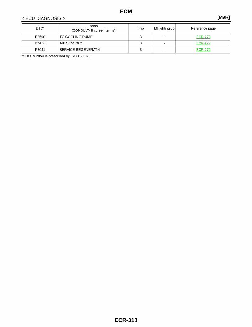
[M9R]ECM
< ECU DIAGNOSIS >
*: This number is prescribed by ISO 15031-6.
P2600 TC COOLING PUMP 3 – ECR-273
P2A00 A/F SENSOR1 3 × ECR-277
P3031 SERVICE REGENERATN 3 – ECR-279
DTC*Items
(CONSULT-III screen terms) Trip MI lighting up Reference page
ECR-318

ENGINE CONTROL SYSTEM SYMPTOMS[M9R]
C
D
E
F
G
H
I
J
K
L
M
A
CR
N
P
O
< SYMPTOM DIAGNOSIS >
E
SYMPTOM DIAGNOSISENGINE CONTROL SYSTEM SYMPTOMS
Symptom Table INFOID:0000000001581701
SYSTEM — Basic engine control system
SYMPTOM
Reference page
HA
RD
/NO
STA
RT
/RE
STA
RT
(E
XC
P. H
A)
EN
GIN
E S
TALL
HE
SIT
AT
ION
/SU
RG
ING
/FLA
T S
PO
T
KN
OC
K/D
ET
ON
AT
ION
LAC
K O
F P
OW
ER
PO
OR
AC
CE
LER
AT
ION
HI I
DLE
LOW
IDLE
NO
STA
RT
(w
ith fi
rst f
iring
)
NO
STA
RT
(w
ithou
t firs
t firi
ng)
HA
RD
TO
STA
RT
WH
EN
EN
GIN
E IS
CO
LD
HA
RD
TO
STA
RT
WH
EN
EN
GIN
E IS
HO
T
AT
IDLE
DU
RIN
G D
RIV
ING
WH
EN
DE
CE
LER
AT
ING
Warranty symptom code AA AB AC AD AE AF
Fuel pump 5 5 5 5 5 5 5 5 5 5 5 —
Fuel injector 3 3 3 3 3 3 3 3 3 4 4 3 3ECR-163, ECR-222
Glow control system 1 1 1 1 1ECR-172, ECR-216
Engine body 3 3 3 3 3 3 3 3 4 4 3 EM-403
EGR system 3 3 ECR-182
Air cleaner and duct 3 3 EM-354
Turbocharger cooling pump 3 3 ECR-273
Electric throttle control actuator 2 2 2 2 1 1 1 1 1ECR-236, ECR-239
ECR-319
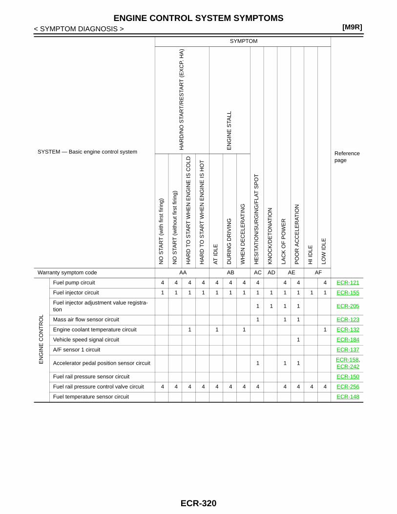
[M9R]ENGINE CONTROL SYSTEM SYMPTOMS
< SYMPTOM DIAGNOSIS >
EN
GIN
E C
ON
TR
OL
Fuel pump circuit 4 4 4 4 4 4 4 4 4 4 4 ECR-121
Fuel injector circuit 1 1 1 1 1 1 1 1 1 1 1 1 1 ECR-155
Fuel injector adjustment value registra-tion
1 1 1 1 ECR-205
Mass air flow sensor circuit 1 1 1 ECR-123
Engine coolant temperature circuit 1 1 1 1 ECR-132
Vehicle speed signal circuit 1 ECR-184
A/F sensor 1 circuit ECR-137
Accelerator pedal position sensor circuit 1 1 1ECR-158,ECR-242
Fuel rail pressure sensor circuit ECR-150
Fuel rail pressure control valve circuit 4 4 4 4 4 4 4 4 4 4 4 4 ECR-256
Fuel temperature sensor circuit ECR-148
SYSTEM — Basic engine control system
SYMPTOM
Reference page
HA
RD
/NO
STA
RT
/RE
STA
RT
(E
XC
P. H
A)
EN
GIN
E S
TALL
HE
SIT
AT
ION
/SU
RG
ING
/FLA
T S
PO
T
KN
OC
K/D
ET
ON
AT
ION
LAC
K O
F P
OW
ER
PO
OR
AC
CE
LER
AT
ION
HI I
DLE
LOW
IDLE
NO
STA
RT
(w
ith fi
rst f
iring
)
NO
STA
RT
(w
ithou
t firs
t firi
ng)
HA
RD
TO
STA
RT
WH
EN
EN
GIN
E IS
CO
LD
HA
RD
TO
STA
RT
WH
EN
EN
GIN
E IS
HO
T
AT
IDLE
DU
RIN
G D
RIV
ING
WH
EN
DE
CE
LER
AT
ING
Warranty symptom code AA AB AC AD AE AF
ECR-320
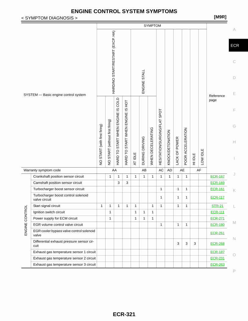
ENGINE CONTROL SYSTEM SYMPTOMS[M9R]
C
D
E
F
G
H
I
J
K
L
M
A
CR
N
P
O
< SYMPTOM DIAGNOSIS >
E
EN
GIN
E C
ON
TR
OL
Crankshaft position sensor circuit 1 1 1 1 1 1 1 1 1 1 ECR-167
Camshaft position sensor circuit 3 3 ECR-169
Turbocharger boost sensor circuit 1 1 1 ECR-161
Turbocharger boost control solenoid valve circuit
1 1 1 ECR-117
Start signal circuit 1 1 1 1 1 1 1 1 1 STR-21
Ignition switch circuit 1 1 1 1 ECR-111
Power supply for ECM circuit 1 1 1 1 ECR-271
EGR volume control valve circuit 1 1 1 ECR-180
EGR cooler bypass valve control solenoid valve
ECR-261
Differential exhaust pressure sensor cir-cuit
3 3 3 ECR-268
Exhaust gas temperature sensor 1 circuit ECR-187
Exhaust gas temperature sensor 2 circuit ECR-231
Exhaust gas temperature sensor 3 circuit ECR-263
SYSTEM — Basic engine control system
SYMPTOM
Reference page
HA
RD
/NO
STA
RT
/RE
STA
RT
(E
XC
P. H
A)
EN
GIN
E S
TALL
HE
SIT
AT
ION
/SU
RG
ING
/FLA
T S
PO
T
KN
OC
K/D
ET
ON
AT
ION
LAC
K O
F P
OW
ER
PO
OR
AC
CE
LER
AT
ION
HI I
DLE
LOW
IDLE
NO
STA
RT
(w
ith fi
rst f
iring
)
NO
STA
RT
(w
ithou
t firs
t firi
ng)
HA
RD
TO
STA
RT
WH
EN
EN
GIN
E IS
CO
LD
HA
RD
TO
STA
RT
WH
EN
EN
GIN
E IS
HO
T
AT
IDLE
DU
RIN
G D
RIV
ING
WH
EN
DE
CE
LER
AT
ING
Warranty symptom code AA AB AC AD AE AF
ECR-321

[M9R]ENGINE CONTROL SYSTEM SYMPTOMS
< SYMPTOM DIAGNOSIS >
1 - 5: The numbers refer to the order of inspection.
(continued on next page)
EN
GIN
E C
ON
TR
OL
Exhaust gas pressure sensor circuit 3 3 ECR-178
Throttle position sensor circuit ECR-134
Refrigerant pressure sensor circuit 2 2 2 ECR-185
ECM relay (Self shut-off) circuit 1 1 1 1 ECR-218
ECM 2 2 2 2 2 2 2 2 2 2 2 2 2
ECR-201,ECR-203,ECR-207, ECR-209
NATS (Nissan Anti-theft System) 1SEC-15, SEC-171
SYSTEM — Basic engine control system
SYMPTOM
Reference page
HA
RD
/NO
STA
RT
/RE
STA
RT
(E
XC
P. H
A)
EN
GIN
E S
TALL
HE
SIT
AT
ION
/SU
RG
ING
/FLA
T S
PO
T
KN
OC
K/D
ET
ON
AT
ION
LAC
K O
F P
OW
ER
PO
OR
AC
CE
LER
AT
ION
HI I
DLE
LOW
IDLE
NO
STA
RT
(w
ith fi
rst f
iring
)
NO
STA
RT
(w
ithou
t firs
t firi
ng)
HA
RD
TO
STA
RT
WH
EN
EN
GIN
E IS
CO
LD
HA
RD
TO
STA
RT
WH
EN
EN
GIN
E IS
HO
T
AT
IDLE
DU
RIN
G D
RIV
ING
WH
EN
DE
CE
LER
AT
ING
Warranty symptom code AA AB AC AD AE AF
ECR-322

ENGINE CONTROL SYSTEM SYMPTOMS[M9R]
C
D
E
F
G
H
I
J
K
L
M
A
CR
N
P
O
< SYMPTOM DIAGNOSIS >
E
SYSTEM — Basic engine control system
SYMPTOM
Reference page
RO
UG
H ID
LE/H
UN
TIN
G
IDLI
NG
VIB
RA
TIO
N
SLO
W/N
O R
ET
UR
N T
O ID
LE
OV
ER
HE
AT
/HIG
H E
NG
INE
CO
OLA
NT
TE
MP
ER
AT
UR
E
EX
CE
SS
IVE
FU
EL
CO
NS
UM
PT
ION
EX
CE
SS
IVE
OIL
CO
NS
UM
PT
ION
AB
NO
RM
AL
SM
OK
E C
OLO
R
DE
AD
BA
TT
ER
Y (
UN
DE
R C
HA
RG
E)
DP
F w
arni
ng li
ght i
llum
inat
es.*
Mal
func
tion
indi
cato
r ill
umin
ates
.
Can
be
dete
cted
by
CO
NS
ULT
-III?
BLA
CK
SM
OK
E
WH
ITE
SM
OK
E
Warranty symptom code AG AH AJ AK AL AM AP HA
Fuel pump 5 5 5 5 3 1 1 —
Fuel injector 3 3 3 4 3 3 1 1 1ECR-163, ECR-222
Glow control system 1ECR-172, ECR-216
Engine body 3 3 3 3 1 3 EM-403
EGR system 3 1 ECR-182
Air cleaner and duct 3 EM-354
Electric throttle control actuator 1 1 1ECR-236, ECR-239
Turbocharger cooling pump ECR-273
EN
GIN
E C
ON
TR
OL
Fuel pump circuit 4 4 4 4 1 1 1 ECR-121
Fuel injector circuit 1 1 1 1 1 1 1 1 1 ECR-155
Fuel injector adjustment value registration 1 1 1 1 1 1 ECR-205
Mass air flow sensor circuit 1 1 1 1 ECR-123
Engine coolant temperature circuit 1 1 1 1 1 ECR-132
A/F sensor 1 circuit 2 1 1 ECR-137
Vehicle speed signal circuit 1 1 ECR-184
Accelerator pedal position sensor circuit 1 1 1ECR-158,ECR-242
Fuel rail pressure sensor circuit 1 1 1 ECR-150
Fuel rail pressure control valve circuit 4 4 4 4 ECR-256
Fuel temperature sensor circuit ECR-148
ECR-323

[M9R]ENGINE CONTROL SYSTEM SYMPTOMS
< SYMPTOM DIAGNOSIS >
1 - 5: The numbers refer to the order of inspection.
*: Although there is no malfunction in the engine control system, DPF warning light may light up because the vehicle is driven in thespecified driving pattern. For the detail, refer to ECR-57, "System Description".
EN
GIN
E C
ON
TR
OL
Crankshaft position sensor circuit 1 1 3 1 1 ECR-167
Camshaft position sensor circuit 3 1 1 ECR-169
Turbocharger boost sensor circuit 2 1 1 ECR-161
Turbocharger boost control solenoid valve circuit
1 1 1 ECR-117
Start signal circuit STR-21
Ignition switch circuit ECR-111
Power supply for ECM circuit 1 1 ECR-271
EGR cooler bypass valve control solenoid valve circuit
3 1 ECR-261
EGR volume control valve circuit 1 1 ECR-182
Differential exhaust gas pressure sensor cir-cuit
2 1 1 ECR-268
Exhaust gas temperature sensor 1 circuit 2 1 1 ECR-187
Exhaust gas temperature sensor 2 circuit 2 1 1 ECR-231
Exhaust gas temperature sensor 3 circuit 2 1 1 ECR-263
Throttle position sensor circuit 1 1 1 ECR-134
Refrigerant pressure sensor circuit 3 4 ECR-185
ECM relay (Self shut-off) circuit 1 ECR-218
ECM 2 2 2 2 2 2 2 2 2 2 2 2
ECR-201,ECR-203,ECR-207, ECR-209
NATS (Nissan Anti-theft System) 1SEC-15, SEC-171
SYSTEM — Basic engine control system
SYMPTOM
Reference page
RO
UG
H ID
LE/H
UN
TIN
G
IDLI
NG
VIB
RA
TIO
N
SLO
W/N
O R
ET
UR
N T
O ID
LE
OV
ER
HE
AT
/HIG
H E
NG
INE
CO
OLA
NT
TE
MP
ER
AT
UR
E
EX
CE
SS
IVE
FU
EL
CO
NS
UM
PT
ION
EX
CE
SS
IVE
OIL
CO
NS
UM
PT
ION
AB
NO
RM
AL
SM
OK
E C
OLO
R
DE
AD
BA
TT
ER
Y (
UN
DE
R C
HA
RG
E)
DP
F w
arni
ng li
ght i
llum
inat
es.*
Mal
func
tion
indi
cato
r ill
umin
ates
.
Can
be
dete
cted
by
CO
NS
ULT
-III?
BLA
CK
SM
OK
E
WH
ITE
SM
OK
E
Warranty symptom code AG AH AJ AK AL AM AP HA
ECR-324

PRECAUTIONS[M9R]
C
D
E
F
G
H
I
J
K
L
M
A
CR
N
P
O
< PRECAUTION >
E
PRECAUTIONPRECAUTIONS
Precaution for Supplemental Restraint System (SRS) "AIR BAG" and "SEAT BELT PRE-TENSIONER" INFOID:0000000001581703
The Supplemental Restraint System such as “AIR BAG” and “SEAT BELT PRE-TENSIONER”, used alongwith a front seat belt, helps to reduce the risk or severity of injury to the driver and front passenger for certaintypes of collision. Information necessary to service the system safely is included in the “SRS AIRBAG” and“SEAT BELT” of this Service Manual.WARNING:• To avoid rendering the SRS inoperative, which could increase the risk of personal injury or death in
the event of a collision which would result in air bag inflation, all maintenance must be performed byan authorized NISSAN/INFINITI dealer.
• Improper maintenance, including incorrect removal and installation of the SRS, can lead to personalinjury caused by unintentional activation of the system. For removal of Spiral Cable and Air BagModule, see the “SRS AIRBAG”.
• Do not use electrical test equipment on any circuit related to the SRS unless instructed to in thisService Manual. SRS wiring harnesses can be identified by yellow and/or orange harnesses or har-ness connectors.
Precaution Necessary for Steering Wheel Rotation After Battery DisconnectINFOID:0000000001581704
NOTE:• This Procedure is applied only to models with Intelligent Key system and NATS (NISSAN ANTI-THEFT SYS-
TEM).• Remove and install all control units after disconnecting both battery cables with the ignition knob in the
″LOCK″ position.• Always use CONSULT-III to perform self-diagnosis as a part of each function inspection after finishing work.
If DTC is detected, perform trouble diagnosis according to self-diagnostic results.For models equipped with the Intelligent Key system and NATS, an electrically controlled steering lock mech-anism is adopted on the key cylinder.For this reason, if the battery is disconnected or if the battery is discharged, the steering wheel will lock andsteering wheel rotation will become impossible.If steering wheel rotation is required when battery power is interrupted, follow the procedure below beforestarting the repair operation.
OPERATION PROCEDURE1. Connect both battery cables.
NOTE:Supply power using jumper cables if battery is discharged.
2. Use the Intelligent Key or mechanical key to turn the ignition switch to the ″ACC″ position. At this time, thesteering lock will be released.
3. Disconnect both battery cables. The steering lock will remain released and the steering wheel can berotated.
4. Perform the necessary repair operation.5. When the repair work is completed, return the ignition switch to the ″LOCK″ position before connecting
the battery cables. (At this time, the steering lock mechanism will engage.)6. Perform a self-diagnosis check of all control units using CONSULT-III.
ECR-325
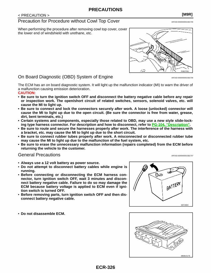
[M9R]PRECAUTIONS
< PRECAUTION >
Precaution for Procedure without Cowl Top Cover INFOID:0000000001581705
When performing the procedure after removing cowl top cover, coverthe lower end of windshield with urethane, etc.
On Board Diagnostic (OBD) System of Engine INFOID:0000000001581706
The ECM has an on board diagnostic system. It will light up the malfunction indicator (MI) to warn the driver ofa malfunction causing emission deterioration.CAUTION:• Be sure to turn the ignition switch OFF and disconnect the battery negative cable before any repair
or inspection work. The open/short circuit of related switches, sensors, solenoid valves, etc. willcause the MI to light up.
• Be sure to connect and lock the connectors securely after work. A loose (unlocked) connector willcause the MI to light up due to the open circuit. (Be sure the connector is free from water, grease,dirt, bent terminals, etc.)
• Certain systems and components, especially those related to OBD, may use a new style slide-lock-ing type harness connector. For description and how to disconnect, refer to PG-104, "Description".
• Be sure to route and secure the harnesses properly after work. The interference of the harness witha bracket, etc. may cause the MI to light up due to the short circuit.
• Be sure to connect rubber tubes properly after work. A misconnected or disconnected rubber tubemay cause the MI to light up due to the malfunction of the fuel system, etc.
• Be sure to erase the unnecessary malfunction information (repairs completed) from the ECM beforereturning the vehicle to the customer.
General Precautions INFOID:0000000001581707
• Always use a 12 volt battery as power source.• Do not attempt to disconnect battery cables while engine is
running.• Before connecting or disconnecting the ECM harness con-
nector, turn ignition switch OFF, wait 3 minutes and discon-nect battery negative cable. Failure to do so may damage theECM because battery voltage is applied to ECM even if igni-tion switch is turned OFF.
• Before removing parts, turn ignition switch OFF and then dis-connect battery negative cable.
• Do not disassemble ECM.
PIIB3706J
SEF289H
MBIB1517E
ECR-326

PRECAUTIONS[M9R]
C
D
E
F
G
H
I
J
K
L
M
A
CR
N
P
O
< PRECAUTION >
E
• When connecting ECM harness connector, fasten (A) itsecurely with levers (1) as far as they will go as shown in thefigure.
- ECM (2)- Loosen (B)
• When connecting or disconnecting pin connectors into orfrom ECM, take care not to damage pin terminals (bend orbreak).Make sure that there are not any bends or breaks on ECM pinterminal, when connecting pin connectors.
• Securely connect ECM harness connectors.A poor connection can cause an extremely high (surge) volt-age to develop in coil and condenser, thus resulting in dam-age to IC's.
• Keep engine control system harness at least 10cm (4 in) awayfrom adjacent harness, to prevent engine control system mal-functions due to receiving external noise, degraded operationof IC's, etc.
• Keep engine control system parts and harness dry.• Handle mass air flow sensor carefully to avoid damage.• Do not disassemble mass air flow sensor.• Do not clean mass air flow sensor with any type of detergent.• Even a slight leak in the air intake system can cause serious incidents.• Do not shock or jar the camshaft position sensor, crankshaft position sensor.• When measuring ECM signals with a circuit tester, never allow
the two tester probes to contact.Accidental contact of probes will cause a short circuit anddamage the ECM power transistor.
• Do not use ECM ground terminals when measuring input/out-put voltage. Doing so may result in damage to the ECM's tran-sistor. Use a ground other than ECM terminals, such as theground.
• Do not disassemble fuel pump.If NG, take proper action.
• Do not disassemble fuel injector.If NG, replace fuel injector.
MBIB1518E
SEF291H
SEF348N
ECR-327

[M9R]PRECAUTIONS
< PRECAUTION >• Do not depress accelerator pedal when staring.• Immediately after staring, do not rev up engine unnecessarily.• Do not rev up engine just prior to shutdown.
• When installing C.B. ham radio or a mobile phone, be sure toobserve the following as it may adversely affect electroniccontrol systems depending on installation location.
- Keep the antenna as far as possible from the electronic con-trol units.
- Keep the antenna feeder line more than 20 cm (8 in) awayfrom the harness of electronic controls.Do not let them run parallel for a long distance.
- Adjust the antenna and feeder line so that the standingwaveradio can be kept smaller.
- Be sure to ground the radio to vehicle body.
• Cylinder NO.1 is at the flywheel end.-1: Crankshaft pulley
ENGINE RUNNING• No work should be carried out on the hydraulic system while engine is running.• Remember that fuel pressure values in hydraulic circuit can reach up to 1,600 bar.• Keep hands or face (particularly eyes) out of any high pressure leak.• Recall that fuel is dangerous for health.
FUEL RAIL PRESSURE SENSOR• Under warranty, do not remove the fuel rail pressure sensor from the rail.• Do not try to measure the resistance of the fuel rail pressure sensor. This test is destructive for the
internal components.
FUEL INJECTOR• Fuel injectors are driven by over 100V.• FUEL injector electronics are polarised. In case of intervention on wiring harness, do not
invertwires. It is destructive for the piezo components.• Do not drive the fuel injectors if their body is not connected to the battery ground (risk ofelectro-
static discharge). For instance, fuel injector body have to be in contact with cylinder.• Piezo fuel injector connector must not be unplugged while engine is running. Risk of majordamage
to the engine (fuel injector could stay opened).
Cleanliness INFOID:0000000001581708
Cleanliness
SEF709Y
SEF708Y
JMBIA0432ZZ
ECR-328

PRECAUTIONS[M9R]
C
D
E
F
G
H
I
J
K
L
M
A
CR
N
P
O
< PRECAUTION >
E
RISKS ASSOCIATED WITH CONTAMINATIONThe high pressure direct injection system is highly sensitive to contamination. The risks associated withcon-tamination are:• damage to or destruction of the high pressure injection system,• components jamming,• components losing seal integrity.All After-Sales operations must be performed under very clean conditions. This means that no impurities (par-ticles a few microns in size) should have entered the system during dismantling.The cleanliness principle must be applied from the filter to the fuel injectors.What are the sources of contamination?• metal or plastic chips,• paint,• fibres:- from cardboard,- from brushes,- from paper,- from clothing,- from cloths,• foreign bodies such as hair,• ambient air• etc.NOTE:Cleaning the engine using a high pressure washer is prohibited because of the risk of damaging connections.In addition, moisture may collect in the connectors and create electrical connection malfunction.
INSTRUCTIONS TO BE FOLLOWED BEFORE CARRYING OUT ANY WORKNOTE:Before any work is carried out on the high pressure injection system, protect:• the accessories and timing belts,• the electrical accessories, (starter, alternator, electric power assisted steering pump),• the flywheel surface, to prevent any diesel from running onto the clutch friction plate.
• Check that you have plugs for the unions to be opened (set of plugs available from the Parts Department).The plugs are single-use only. After use, they must be discarded (once used they are soiled and cleaning isnot sufficient to make them reusable). Unused plugs must be discarded.
• Check that you have hermetically resealable plastic bags for storing removed parts. Stored parts will there-fore be less subject to the risk of impurities. The bags are to be used once only, and discarded after use.
• Use lint-free cleaning cloths. Using normal cloth or paper is prohibited. They are not lint-free and could con-taminate the fuel circuit. Each cloth should only be used once.
• Use fresh cleaning agent for each operation (used cleaning agent is contaminated). Pour it into an uncon-taminated container.
• For each operation, use a clean brush in good condition (the brush must not shed its bristles).• Use a brush and cleaning agent to clean the unions to be opened.• Blast compressed air over the cleaned parts (tools, workbench, the parts, unions and injection system
zones). Check that no bristles remain.• Wash your hands before and during the operation if necessary.• When wearing leather protective gloves cover them with latex gloves to prevent contamination.
INSTRUCTIONS TO BE FOLLOWED WHEN CARRYING OUT ANY WORK• As soon as the circuit is open, all openings must be plugged to prevent impurities from entering the system.
The plugs to be used are available from the Parts Department. The plugs must not be reused under any cir-cumstances.
• Seal the pouch shut, even if it has to be opened shortly afterwards. Ambient air carries contamination.• All components removed from the injection system must be stored in a hermetically sealed plastic bag once
they have been plugged.• Using a brush, cleaning agent, air gun, sponge or normal cloth is strictly prohibited once the circuit has been
opened. These items could allow contamination to enter the system.• A new component replacing an old one must not be removed from its packaging until it is to be fitted to the
vehicle.
ECR-329

[M9R]PREPARATION
< PREPARATION >
PREPARATIONPREPARATION
Special Service Tools INFOID:0000000001605922
Commercial Service Tools INFOID:0000000001605923
Tool numberTool name
Description
KV10114400Heated oxygen sensor wrench
Loosening or tightening heated oxygen sensor 2a: 22 mm (0.87 in)
S-NT636
Tool name Description
Oxygen sensor thread cleaner
Reconditioning the exhaust system threads before installing a new oxygen sensor. Use with anti-seize lubricant shown below.a: 18 mm diameter with pitch 1.5 mm for Zirco-nia Oxygen Sensorb: 12 mm diameter with pitch 1.25 mm for Tita-nia Oxygen Sensor
Anti-seize lubricant
i.e.: (PermatexTM 133AR or equivalent meeting MIL specifica-tion MIL-A-907)
Lubricating oxygen sensor thread cleaning tool when reconditioning exhaust system threads.
AEM488
S-NT779
ECR-330

SERVICE DATA AND SPECIFICATIONS (SDS)[M9R]
C
D
E
F
G
H
I
J
K
L
M
A
CR
N
P
O
< SERVICE DATA AND SPECIFICATIONS (SDS)
E
SERVICE DATA AND SPECIFICATIONS (SDS)SERVICE DATA AND SPECIFICATIONS (SDS)
Idle Speed INFOID:0000000001581709
*: Under the following conditions
• A/C switch: OFF
• Electric load: OFF (Lights, glow plug, heater fan & rear window defogger)
• Steering wheel: Kept in straight-ahead position
Condition Specification
No load* (in Neutral position) 750 ± 50 rpm
ECR-331