
Engine Dynamic Analysis With General Nonlinear Finite Element · PDF file ·...
94
NASA Contractor Report 187222 Engine Dynamic Analysis With General Nonlinear Finite Element Codes M.L. Adams, J. Padovan and D.G. Fertis University of Akron Akron, Ohio (NASA-CR-187222) ENGINF DYNAMIC ANALYSIS WITH GENERAL NONLINEAR FINITE ELEMENT CODES Final Report (Akron Univ.) 93 p CSCL 20K G3/39 N92-11379 Unclas 0048390 October 1991 Prepared for Lewis Research Center Under Grant NSG3-283 NASA National Aeronautics and Space Administration https://ntrs.nasa.gov/search.jsp?R=19920002161 2018-05-17T13:06:38+00:00Z
Transcript of Engine Dynamic Analysis With General Nonlinear Finite Element · PDF file ·...
NASA Contractor Report 187222
Engine Dynamic Analysis With GeneralNonlinear Finite Element Codes
M.L. Adams, J. Padovan and D.G. FertisUniversity of Akron
Akron, Ohio
(NASA-CR-187222) ENGINF DYNAMIC ANALYSIS
WITH GENERAL NONLINEAR FINITE ELEMENT CODES
Final Report (Akron Univ.) 93 p CSCL 20K
G3/39
N92-11379
Unclas
0048390
October 1991
Prepared forLewis Research CenterUnder Grant NSG3-283
NASANational Aeronautics and
Space Administration
https://ntrs.nasa.gov/search.jsp?R=19920002161 2018-05-17T13:06:38+00:00Z


TABLE OF CONTENTS
SOUEEZE-FILNDARPER IMPLANT INTO ADINA - A DEMONSTRATION
NUmeRICAL CONSIDERATIONS AND EXAMPLES
8.1 Benchmarking8.2 Explicit and Implicit Direct Integration Methods8.3 Demonstration Problems
9. EXPERIMEh_AL STUDIES
9.1 Review of Some Recent SFD Studies
9.2 Experimental Facility9.3 Experimental Method and Objectives9.4 Experimental Results9.5 Comparison with a Simplified Computer Model
I0. SUMMARYAND CONCLUSIONS
_ection
I. INTRODUCTION AND BACKGROUND
2. TIME-TRANSIENTNONLINEARDYNAMICANALYSES
3. OVERALL APPROACH USING INTERACTIVE ELEMENTS
4. SOUEEZE-FILM DAMPER ELEMENT DEVELOPMENT
5. METHOD OF DAMPER ELEMENT SOLUTION
8. DEMONSTRATION OF DAMPER ELEMENT
7.
8.
ACKNOWLEDGFJ4ENTS
REFERENCES
NOMENCLATURE
ILLUSTRATIONS
1
5
7
8
11
18
20
2021
2S
sQ
g4
$5
87
4O
41
This report summarizes a three-year scope of work at the University of
Akron within the field of transient/nonlinear dynanic analysis of gas
turbine jet engine structures. Dr. C. C. Chanls was the I_L_SA-Levls
Technical nonitor of this |rant. The focus of this work was on the
development and inplenentation of rotor-stator interactive force el enents
for Inplant into general purpose nonlinear tlne-transient flnite-elenent •
codes suitable for general engine dynanic ainulation. The Principal
Investigators on this grant vereDrs. M.L. Adans e, I. Padovan and D. G.
Fertis of the University of Akron.
portions of this work were I. Zeid.
P. Lan.
Graduate students involved with various
R. Quinn, E. Hirt, $. Payandeh and
• Now Professor of Mechanical Engineering at Case Western Reserve
University, Cleveland, Ohio 44106.

INTRODUCTION AND BACEGRObTqD
There is currently a considerable interest and level of activity in
developing computational schemes to predict general engine dynamic
behavior. The general feeling among knowledgeable parctitioners working on
engine vibration problems is that various modes of operation, such as
blade-loss events, require • high level of analysis sophistication to
realistically model the engine. Proper account of system nonlinearities
(particularly at the bearings, dampers and rubs) appears to be necessary if
analytical predictions are to be realistic. The approach used in this work
makes use of already proven general finite-element nonlinear time-transient
computer codes which are available on the open market. The work speclfi-
c•lly described covers • three-phase NASA-Levis sponsored research grant on
engine dynamic simulation with available finite element codes. Phase -_..i
concentrated on the development of a bearing-damper element computer soft-
ware package suitable for 'plug-in' to available finite element codes.
Phlse -_. focused on the implanting of tbls damper element into the ADINA
code and extensive computational testing of the completed package. Phase -J.
was related experimental york on a new test rig employing • flexible rotor
mounted in two squeeze-film dampers.
Present-day jet engine configurations have evolved to a substantial
degree through a trial-and-error process involving extensive testing. There
are many fundamental dynamic phenomena which take place within these engines
for which basic description and understanding have yet to be generated.
Nonetheless, they work well. Modern aircraft engines are typical of current
high-technology products in which the recently acquired computing capabili-
ties of today are being used to better understand and improve what is

already designed, bnllt and operating.
A better nnderstsndins of the basic dynamic characteristics of existing
and new engine configurations is a prerequisite for producing acceptable
engine efficiencies on advanced configurations (i.e., smaller xotor/stator
running clearances). Also, a better definition of engine dynamic response
would more than likely provide valuable information and insights leading to
reduced maintenance and overhaul costs on existing configurations. Further-
more, application of advanced engine dynamic simulation methods could
potentlally provide • considerable cost reduction in the development of new
engine configurations by eliminating some o_ the trial-and-error process
done with engine hardware development.
The emergence of advanced finite element codes, such as NASTRAN,
NONSAP, MARC, ADINA, ANSYS and ABAQUS and related algoritlueic advances, has
placed comprehensive engine system dynamic analyses within reasonable reach.
What remains to be done is to develop new component element software to
properly model engine rotor/stator interactive components, such as the
squeeze-film damper, within the algorithmic logic of already proven finite
element codes. This has been • major mission of this work.
For good reasons, aircraft gas turbine engines use rolling element
bearings exclusively. This design philosophy bad, in earlier times,
deprived engines of the beneficial damping inherent in many other types of
rotating machinery where fluid-film journal bearings are used. The
implementation of squeeze-film dampers in later engine designs has now
provided engine designers with an effective means of vibration energy dis-
sipation. The net result is that engines with squeeze-film dampers are less
sensitive to residual rotor imbalance and better able to control vibration
and transmitted force levels resulting from various excitation sources
within the engine.
The field of rotor dynamics has evolved to its present state primarily
through the solution to problems in classes of machinery older than aircraft
engines. _n most other types of rotating machinery (e.g., steam turbines,
centrifugal pumps and compressors, fans, generators, motors, etc.) the rotor
can be adequately modelled ts •n Euler or Timoshenko bean [I]. In addition,
the support structure holding each bearing can often be adequately modelled
as a separate mass-damping-stiffness path to ground (i.e., to the inertial
frame). Also, for most purposes, bearing dynamic properties are
char•cterlzed as stiffness and damping elements, line•rized for small
vibration amplitudes about some static equilibrium state. Wlth few excep-
tions (e.g., Hibner [2]), it is this level of sophistication that has been
utilized for the most part is rotor-dynamics analyses of aircraft engines.
Present day aircraft engines are structur•11y far more complex than
most other types of rotating machinery. The multi-shaft configuration, plus
the fact that the shafts are thin rotating shells, creates unique but sig-
nificant complicating differences between aircraft engines and other turbo-
machinery. Also, the st•tot structural support •t each rotor bearing repre-
sents anything but • separate mass-damper-stiffness path to an inertial
frame. In fact, setting the inertial frame for the engine is not • simple
matter when the full range of in-service maneuvers is realized. Dynamic
paths between different bearings exist not only through the rotor but
through several other paths within the nonrotating engine structure, i.e., a
'multi-level', 'nultl-branch' system. As many as eight significant 'levels °
have been identified.
$
The feasibility of nonlinear dynamic analyses of multi-bearins flexible
rotors has been recently denonstrated on non-aircraft applications [3].
There are highly nonlinear dynanic effect in aircraft engines, particularly
under large excitation forces, such as blade or disk failures, hard land-
inss, and forelsn hatter insestion events.
Clearly, the field of aircraft engine dynamics is presently in a
position where there is both a need for substantial advances and feasible
neans available by which such advances can be acconplished.
4
2. TX),_-_SXE_r NONLI_ DYN_IC ANALYSES
In recent years it has become evident that an important class of en$ine
dynamic phenomena can not be studied without accounting for the hishly non-
linear forces produced at bearings/dampers, labyrinths and other close-
running rotoz/stator clearances under larle amplitude vibrations. In such
cases, linear theory typically predicts vibration amplitudes farmer than the
actual runninl clearances. Furthermore, important vibratory phenomena, such
as subharnonic resonance and motion limit cycles, are 'filtered' out of the
problem with a linear model, living srossly erroneous predictions,
qualitatively as well as quantitatively [3].
With few exceptions, nonlinear dynamics problems must be solved
numerically as time-transient responses, whether the sought answer is a
steady-state periodic motion or is strictly a transient phenomenon. The
problem is mathematically categorized as an initial value problem in which
the displacements and velocities of the complete system must all be
specified at the beginning of the transient. From that point forward in
time, the equations of motion are numerically intejrated (known as
'marchinB') as far in time as one wishes to study the system motions end
forces. If the system is dynamically stable, the transient motion dies out
yieldin| the steady state response which in most real systems with a perio-
dic force excitation will be a periodic motion. In a stable system with no
time-vsrylns force excitation, the transient will die out as the system
comes to rest at one of its stable static equilibrium posltions. If the
system is unstable, the transient does not die out but continues to |roy in
time unless or until some nonlinear mechanism in the system limits the
motion to what is frequently called a 'limit cycle' [3].

In order to study the general dynamical characteristics of aircraft
ensines, nonlinear dynamics computational schemes are required. The
approach taken is to develop software packages to model eusine components
which are not typically found on dynamical structures and therefore are not
already built into existing nonlinear finite element structural dynamics
computer codes. The initial effort has concentrated on developins such a
software package for squeeze-film bearing dampers.
3. OVERALL _PPROACH USING INTERACTIVE ELEMENT,S
Considering the typical engine structural complexities, an improved
computational approach is necessary if a proper transient/steady-state model
is to be developed for gas turbine engines. In this approach, it appears
that the finite element method is one of the attractive modelling techniques
for such problems. Its inherent capabilities include features essential to
modern engines: I) automatically handles multi-branch, multi-level struc-
tures in a more direct and efficient manner than flexibility approaches,
2) ve11-suited to handle nonlinearities associated with structural kinematic
and kinetic effects [4], 3) easily accommodates various types of boundary
and constraint conditions, and 4) easily accommodates material nonisotropy
and nonlinearity [4,5]. A body of established and proven algorithms are
available which can handle these various important effects [4,6] as well as
geometric complexities, e.g., beam, plate, 2-D and $-D elements [7].
The required features which were not previously available with general
purpose finite-element codes are provisions to handle rotor/stator
interactive forces originating from squeeze-film dampers, seals and rub/
impact events. Presented in the next three Sections of this report are the
_esults of an effort to develop a squeeze-film damper computer software
package which can be 'plugged' into any existing finite element code.
T
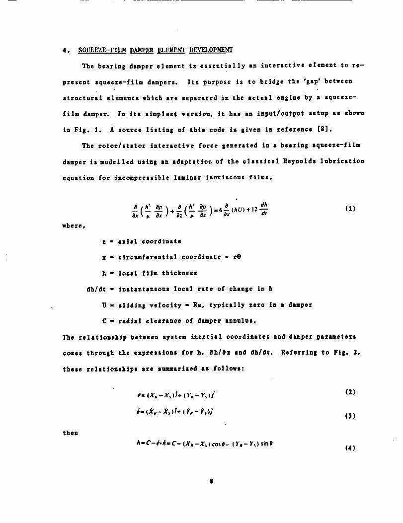
4. SqUEEZE-FILM DAMPER ELEMENT pEV_OP_
The bearing damper element is essentially an interactive element to re-
present squeeze-film dampers. Its purpose is to bridge the 'gap' between
structural elements which •re separated in the actual engine by • squeeze-
film damper. In its simplest version, it has an input/output setup as shown
in Fig. 2. A source listing of this code is given in reference [8].
The rotor/stator interactive force generated in • bearing squeeze-film
damper is modelled using an adaptation of the classical Reynolds lubrication
equation for incompressible laminar isoviscous films.
where,
(1)
z = axial coordinate
x = circumferential coordinate = rO
h = local film thickness
dh/dt = instantaneous local rate of change in h
U = sliding velocity ffi I_, typically zero in a damper
C = radial clearance of damper annulus.
The relationship between system inertial coordinates and damper parameters
comes through the expressions for h° Oh/Bx and dh/dt. Referring to Fig. 2,
these relationships are summarlzed as follows:
then
_= (Xx -Xs)Y+ ( )'k - Y_)f
hfC-d.d=C- (Xs-X_) cos0- ( )'m- Ys) sin 0
(2)
(3)
(4)
8

Oh I _b I
a'_ = "R ¢_--0= "R [(Xx-X_lsinO-(Ym- Y._) cosO] (5)
and
dh= - (XR - X_ ) cos 0- ( Yk - f's ) sin ed"7 ( 6 )
Many configurations of dampers which are currently bein8 employed in
ensines have done away with centexinl sprlnjs common in older deaisns.
Desisn simplicity as well as centerin$-spring fatisue life are apparently
the major reasons. Also, in the majority of cases, damper end seals are
used because this keeps damper throughflow sufficiently low to be compatible
with the overall engine lub system of pre-d•mper confisutationa. However,
the disadvantase of havin| end seals is that a 'larse' damper clearance of
typically 10 mils is required in order for the squeeze-film action to effec-
tively dissipate vibration enersy. From other considerations, • smaller
damper clearance would be desirable (e.g., blade tip clearances). Without
end seals, the optimum damper clearance is considerably smaller. Ensines
with hizher oil flow capacity and no damper end seals are probably the trend
on future desisns.
Two typical confisurations are shown in Fils. 3 and 4. The end seal
confis_ration in Fils. 3 and 4(a) essentially divides the lubricant annulus
into two pressure domains whereas that in Fi s. 4(b) is a one-domain problem.
In both cases, the 'lons-bearinl' solution is appropriate. Both solutions
are options in the software package developed in this work.
For the 'lonj-bearins' solution ap/az <( ap/_x, and the followin$ ordi-
nary differential equation (two point boundary value problem) is obtained
from equation (1), for U = 0.
9

For configurations with no end seals, an inproved adaptation of the
short-bearing approach is used by inplenenting the parabolic assumption of
O'Donoghue [9]. The following approximation is nade:
p(O,.:) =p(8,O)(I - 4::(8)
This assunes an axially symnetric axial pressure distribution at every cir-
cumferentlal location, and results in the following pressure field equation.
I a ap dh 8p(e,O)h' (9),, ax("' )=,2 + ---- _ _T L:
This is actually a first-order Fourier approxinatlon using the parabola as
the single approxinative function.
A convergent approxi,,stion to the full two-dimensional Reynolds equation
can be obtained, as an extension of the foregoing approach by O'Donoghue [9].
The number of Fourier terms is increased to N, resulting in N sinultaneous
ordinary differential equations.
(2N-p(O.:} I)r:.co__- +p:(e.o)co,._ +... +p, (e.o)cos
Z(lO)
Substitution Into the general 2-D Beynolds equation (1), followed by LHS:RHS
segregation by arguments ylelds N ordinary differential equations, one for
each p;(e,o), [9].
1o
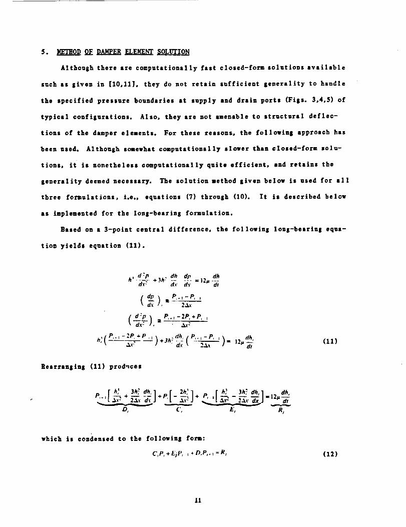
Although there are computationally fast closed-formsolutions available
such as given in [10,11], they do not retain sufficient generality to handle
the specified pressure boundaries at supply and drain ports (Figs. 3,4,5) of
typical configurations. Also, they are not amenable to structural deflec-
tions of the damper elements. For these reasons, the following approach has
been used. Although somewhat computatioually slower than closed-form solu-
tions, it is nonetheless computational ly quite efficient, and retains the
generality deemed necessary. The solution method given below is used for all
three formulations, i.e., equations (7) through (10). It is described below
as Implemented for the long-bearing fornulatiou.
Based on a 3-point central difference, the following Ions-bearing equa-
tion yields equation (II).
h ' d : p dh dp dh-d¥..---,-3h: h._- dT =12_ h,
do P,.n-P, ,) = 2.._
d:p P,.,-2P,+P, ,
( - ) "(",-,-", )P,., 2P _P., +3h: " "-- ' = 12_--h; ..%a': ' "d._" _-.._ dl
Rearranging (11) prodncea
r h: ÷ --.3h_dh_._1 +p,[_ 2h_1 p r h_ 3h_dh,I dh,P,.,.J
13, C', I"i R,
which is condensed to the following form:
C,P,+_P, .4D.P,.j=k,
(11)
(12)
11
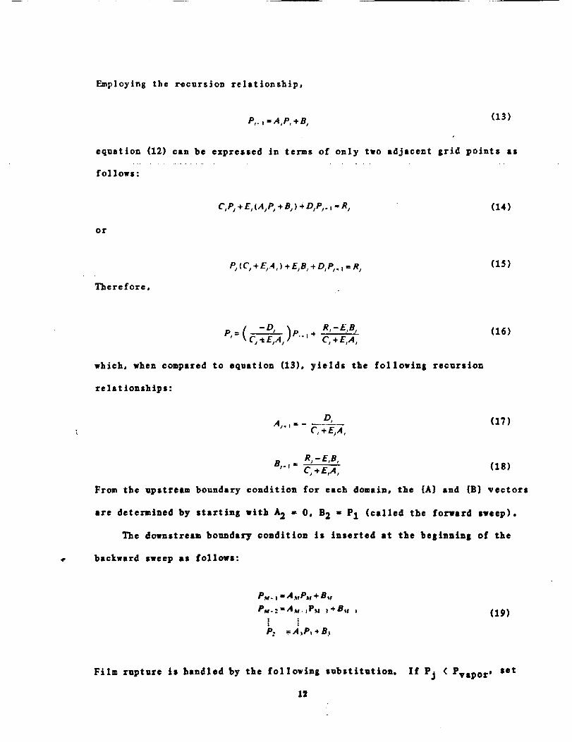
Employing the recursion relationship,
Ps- I = A,P, + Bj(13)
equation (12) can be expressed in ter_s of only two adjacent grid points as
follows:
or
C,P,+E_,A,P,.e,)*D_P,.,-R, (14)
Therefore.
P,(Q +Ej.4, ) +EjB, + D,P,, . =R, (15)
R - E, Bj-O, )p...e' = (¢,-_E,% ' C,+E,,4,
which, when compared to equation (13), yields the followins recursion
relationships:
(16)
D, (17)
41'
B,., = Rj-E,B,_+E,A, (18)
From the upstream boundary condition for each domain, the (A) and (B} vectors
are determined by starting with A 2 = 0, B 2 = P1 (called the forward sweep).
The downstream boundary condition is inserted at the be$innin| of the
backward sweep as follows:
PM :'AM ,PM '*Bar ,
P: = A_P_ "+B_
(19)
Film rupture is handled by the followins substitution.
12
If Pj ( Pvapor" set
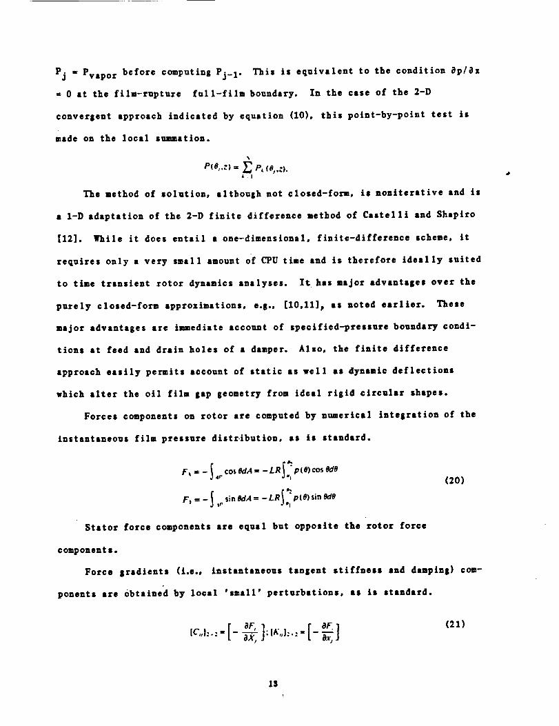
Pj = Pvapor before computing Pj-I" This is equivalent to the condition BplBx
= 0 •t the film-rupture full-film boundary. In the case of the 2-D
convergent approach indicated by equation (I0), this point-by-polnt test is
made on the local summation.
e(e,.:)=_p,(_.:)i|
The method of solution, although not closed-form, is noniterative and is
• I-D adaptation of the 2-D finite difference method of Castelli and Shapiro
[12]. While it does entail • one-dimensional, finite-difference scheme, it
requires only a very small amount of CPU time and is therefore ideally suited
to time transient rotor dynamics analyses. It has major advantages over the
purely closed-form approximations, e.g., [10,11]p as noted earlier. These
major advantages are i,mediate account of speclfied-pressure boundary condi-
tions at feed and drain holes of s damper. Also, the finite difference
approach easily permits account of static as well as dynamic deflections
which alter the oil film gap geometry from ideal rigid circular shapes.
Forces components on rotor are computed by numerical integration of the
instantaneous film pressure distribution, as is standard.
F_=-[ cosSdA=-LR plO)cosedOJ 4¢' R (20)
s?-_ $in edA = -LR p(0)sinedOF_=J ip 0
Stator force components •re equal but opposite the rotor force
components.
Force gradients (i.e., instantaneous tangent stiffness and damping) com-
ponents are Obtained by local 'small' perturbations, as is standard.
IE,,): . [_ aF, aF(21)
15

where
------_-;_ = (22)ax, _x, ax, _;
with s,.all AXj and _j incrementsNumerical differentiation is performed
about instantaneous conditions. This provides continuous updating of {Fj},
[Cij] and [Kij].
14
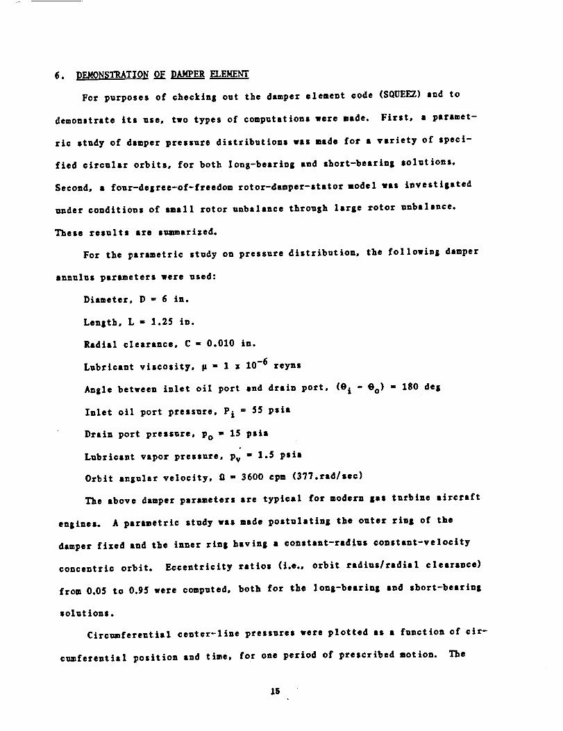
6. pF._tON_TI_TION OF _ ELEP_ENT
For purposes of checklns out the damper element code (SQUEEZ) and to
demonstrate its use, two types of computations were made. First, a paramet-
ric study of damper pressure distributions was made for a variety of speci-
fied circular orbits, for both long-bearlns and short-bearlns solutions.
Second, a four-desree-of-freedom rotor-damper-stator model was investigated
under conditions of small rotor unbalance throush large rotor unbalance.
These results are summarized.
For the parametric study on pressure distribution, the following damper
annulus parameters were used:
Diameter, D = 6 in.
Length, L - 1.25 in.
Radial clearance, C = 0.010 in.
Lubricant viscosity, p = I z 10 -6 reyns
Angle between inlet oil port and drain port, (O i - 00 ) = 180 des
Inlet oli port pressure, Pi = 55 psla
Drain port pressure, Po = 15 psia
Lubricant vapor pressure, Pv = 1.5 psia
Orbit angular velocity, fl - 3600 cpm (3?7.tad/see)
The above damper parameters are typical for modern 88s turbine aircraft
engines. A parametric study was made postulating the outer ring of the
damper fixed and the inner ring having a constant-radius ¢onstant-veloclty
concentric orbit. Eccentricity ratios (i.e., orbit radius/radlal clearance)
from 0.05 to 0.95 were computed, both for the long-bearing and short-bearing
solutions.
Circumferential center-line pressures were plotted as a function of cir-
cumferential position and time, for one period of prescribed motion. The
15

results for the lens-bearing solution are shownin Fig. 6, and for the short-
bearing solution in Fig. 7. The difference between long-bearing and short-
bearing solution is quite large when compared with the sane radial clearance.
One therefore sees why dampers with end seals require larger clearances to
work properly than dampers without end seals.
A simple 'drlvcr' code was written (see I/sting [8]) which use• the
damper-element code in the same manner •s a general implanted application
with large finite element codes. The 'driver p code is based on • four--
degree-of-freedom system, i.e., planar motion of the inner and outer damper
elements. This then ainnlates • single-ma_s rotor connected to • single-
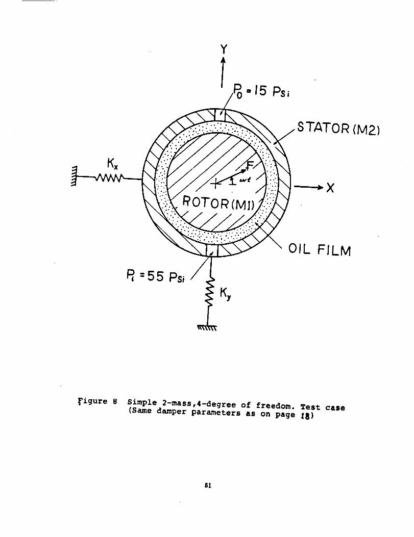
mass st•tot through the damper element. The system analyzed is shown in
Fig. 8. The model is coded to simulate arbitrary rotating and/or static
radial loads. Aside from demonstration purposes, this four-degree-of-
freedom model has been devised as • 'bench tester' of different damper
models and configurations.
Note frol Fig. 8 that the high-pressure port (i.e., feed port) Is
located on the bottom of the damper so as to assist 'lift-off'. Since
centering springs are not typically used, they have been excluded in this
example, being the most nonlinear type case and therefore computation•fly
the nest demanding of the algorithms employed. Lift-off therefore requires
some amount of vibration to overcome the dead-wel|ht load. Rotating
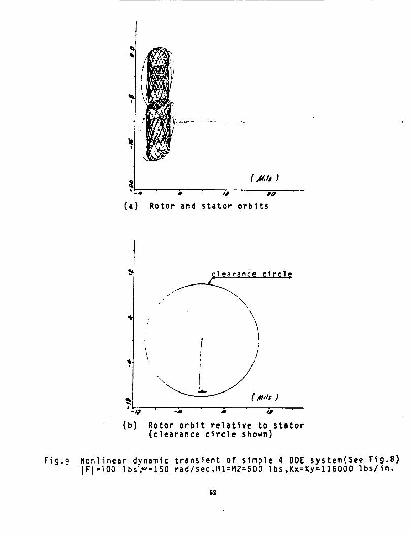
unbalance loads of I00, 200, 300, $00, end I000 Ibm were run vlth _ = 150
r•d/s. Orbital plots were made •hewing rotor and st•tot total notion on one
plot and rotor-relative-to-st•tot notion on a second plot. The plotted
results are shown in Figs. 9 through 13.
For • I00 Ib rotating load (Fig. 9) the motions shown are for • 20
load-cycle transient frog time - 0. The rotor and st•tot each show close to
16

the same motion, and their relative motion is small, with the rotor barely
'llftinj off'. The relative orbit is essentially oscillatory. Bowever,
when the rotatin$ load is increased to 200 Ibs, (Fin. 10), the relative
orbital motion shows the besinnings of orbital motion, i.e., a 'crescent
moon' shape as measured by numerous investisators. Further increase in
masnitude of the rotatinj load to 300 Ibs (Fin. ll) shows a veil-defined
steady-state total motion as well as relative motion. Note that with a 300
Ibs rotatins load, the relative (rotor-to-stator) orbit is still small in
comparison to the radial damper clearance and confined to the resiou of the
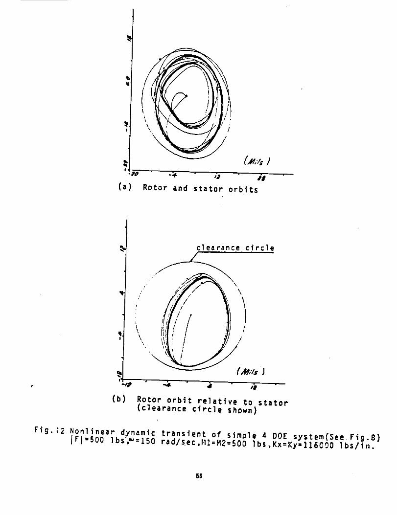
bottom of the damper. Bovever, an increase of rotatin8 load magnitude to
500 Ibs causes a considerable change to the relative orbit (Fin. 12).
Notice now that the relative notion of the rotor with respect to the stator
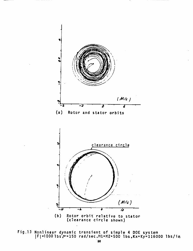
fills a major portion of the clearance circle. Further increase of rotatinj
load maanitude to I000 Ibs (Fin. 13) simply causes the steady-state relative
orbit to expand and fill even more of the damper clearance circle.
I?

7. _OUEEZE-FILM DAMPER !MPLAN'rINTOADINA - _ _EMONSTRATION
The squeeze-film damper element (SQUEF_,Z), described in previous
Sections of this report, is also summarized in references [8] and [13].
Reference [8] also contains Fortran computer code listings for the damper
element •s well •s for the four-degree-of-freedom driver code used in its
development and demonstration.
To demonstrate the implementation of the SQUEEZ element into • general
purpose transient nonlinear finite element (FE) code the ADINA code was
purchased from MIT by the University of Akron •s • cost-sharing expenditure.
The next group of Sections in this report describe the implant of SQUEEZ
into the ADINA code, • general purpose nonlinear FE code well known and used
throughout the field of structural mechanics. This implant work is also
summarized in references [14] and [I$], vith complete Fortran listings of
all generated software and graphics packages given in reference [15].
To benchmark the approach described in references [14,15], the appro-
priate general purpose finite element code had to be selected. As noted in
the first year report [13], the ADINA code was chosen for this purpose.
This follows from the fact it has the requisite features required for rotor-
bearing-ststor simulations. These include: (i) Linear and nonlinear
snbstructuring features, (ii) An extensive element library, (iii) Capability
to handle kinetic, kinematic and material nonlinearity, (iv) Explicit and
implicit integration loops, (v) Simplified I/0 features, (vi) Accessible
code architecture, (v/i) Extensively benchmarked, and (viii) Requisite
portability and general availability. In terms of the squeeze-flln damper
element noted in [8], extensive modifications were introduced into the ADINA
code. These modifications were made general enough so as to handle rotor-
bearing-st•tot simulations involving any number of rotors and associated
18
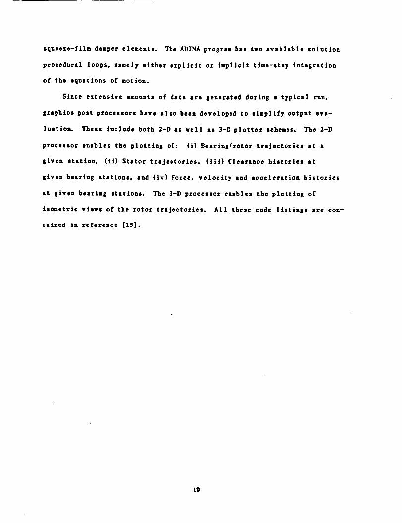
squeeze-film damper elements. The ADINA program has two available solution
procedural loops, namely either explicit or implicit time-step integration
of the equations of motion,
Since extensive amounts of data are generated during 8 typical run,
graphics post processors have also been developed to simplify output eva-
luation. These include both 2-D as well as 3-D plotter schemes. The 2-D
processor enables the plotting of: (i) Bearing/rotor trajectories at a
given station, (ii) Stator trajectories, (iii) Clearance histories at
given bearing stations, and (iv) Force, velocity and acceleration histories
at given bearing stations. The 3-D processor enables the plotting of
isometric views of the rotor trajectories. All these code listings are con-
tained in reference [15].
19

8. NUMERICALCONSIDERATIONS _ EXAMPLES
This Section describes the work pertaining to the computational charac-
teristics of ADINA-wlth-SQUEEZ direct integration approach of FE generated
rotor-bearing-housing motion simulations.
8.1 Benchmarkina
To benchmark the overall procedure, a simple lumped parameter direct
integration scheme was developed. This approach was used to check the
accuracy of the FE generated scheme involving the ADINA-SQUEEZ 'implant'.
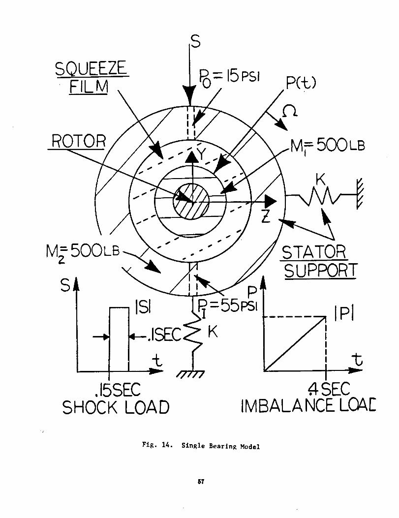
As the first example of such benchmarking, consider the system defined in
Figure (14). The material and geometric properties associated with the dual
ported squeeze-film damper bearing employed in this and the following sample
problems are defined by
Nominal diameter = 6 inches,
nominal length = 1.2 inches,
Clearance = 1. inch, viscosity - .le10 -$,
film rupture pressure = 15 psia,
01 = 90, o 2 = 270, Pl = 15 psi, P2 = 55 psi. Note as with current
practice, the bearing used in the simulation has no centering spring. In
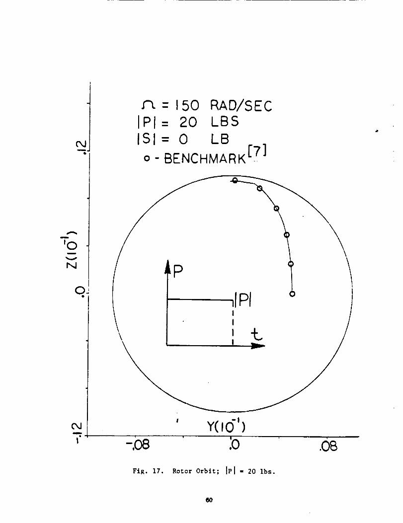
terms of this system, Figs. (15-17) illustrate various aspects of the
validation of the Newark [16], Vilson [17] and central difference |enerated
results with those of the benchmark. ]n this way, both the implicit and ex-
plicit schemes are treated. In each of the comparisons, three different
aspects of rotor bearing stator behavior are depicted specifically.
a) Rotor displacement trajectories,
b) Stator displacement trajectories, and
¢) Relative rotor orbit.
2O
For the present purposes, while extensive benchnarking was undertaken,
for convenience, only the case of mild rotor unbalance is depicted. As can
be seen, for the siren At steps chosen, mood comparisons were obtained by
both the implicit and explicit schemes. Such benchnarkins was obtained over
a vide range of rotor speeds and rotor unbalance levels. In •11 cases, mood
accuracy was yielded. Similar benchn•rking was •1so perfomed for multi-
bearins-rotor-st•tor •inulationa. Note, so long as At va• kept small, mood
accuracy was obtained over • vide ranse of system variables.
8.2 Explicit and Implicit l)irecte_p___q2__S.!_t_Mcthods
For problems involvins few degrees of freedom, it was found that for •
given accuracy, both the implicit and explicit schemes required about the
same overall computational times. This follows from the fact that for
'small problems', the architectural overhead associated with the implant
strategy prosrammin$ dominates over the relative alsorithmie efficiency.
Note for transients initiated by rather severe unbalance loads, it was found
that the implicit scheme proved to be more sensitive to the choice of time
step size. Interestingly, such sensitivities were found to occur for
problems with small as well as larse numbers of desrees-of-freedom. After
perforwlng several parametric studies, it was found that during the course
of • typical transient, particularly involvins a severe loading, the tangent
properties of the fluid film underjo major changes. Because of this, • per-
fusion of system harmonics are introduced into the transient response as the
tangent fluid film properties vary. Note, this behavior is intrinsic to the
fluid film'•rid hence, is independent of the number of de•tees-of-freedom of
the rotor-stator model. Such properties tend to reduce the stability thres-
hold of the implicit scheme which is best employed when only a few harmonics
21

• re ezcited. For problems involving large numbers of degrees-of-freedom,
the sensitivity of the implicit scheme coupled wlth the required continuous
updating and inversions of the dynamic stiffness tends to reduce the running
efficiency of the procedure. In contrast, the central difference approach
tends to be less sensitive to such tangent property fluctuations. This is
true so long as the resulting family of harmonics is bound by the spectral
characteristics of the rotor-st•tot system. Because of this, similar At can
be employed by the implicit and explicit scheme. In this context, the
explicit scheme has • somewhat better computational efficiency than the
implicit approach. This follows from the fact that no continuous inversion
is required by the explicit scheme.
8.3 _JE_ZJLYJL_U_ Problems
To demonstrate the various capacities of the ADINA implant strategy,
the results of several example problems will be considered. This will
involve single and multiple be•ring problems with various types of rotor
unbalance histories, impact events and rotor speeds. For example, in terms
of the •ingle bearing system given in Fig. (14), Figs. (18 and 19)
illustrate various aspects of the response histories to an imbalance load
which is applied •s • ramp function in time. As this loadini is more severe
than that •pplled in Figs. (15-27), the rotor tends to fill its clear•nee
circle as seen in Fig. (19). If the same system is subject to • unidirec-
tional impulse, as might be expected from • rough landing 3 Figs. (18) and
(20) illustrate the associated response history. By comparin s Figs. (18)
and (20), the effects of the impulse can be clearly seen from the ovalizlns
of the rotor trajectories. This is directly due to the directional ch•rac-
teristics of the impulse load, Note, comparlns the results in Fig. (19), we
22

see that the rotor orbits •re essentially unchanged by the presence of the
shock load. Bence, it follows that the squeeze-film d•mper has essentially
no effect on mitigating the worst •spects of unidirectional shocks when
larse unbalances •re simultaneously present.
The next series of examples pertains to the rotor-bearins-st•tor system
defined in Fig. (21). To simul•te the shaftins, the beam elements •vailable
in the ADINA system are utilized. Note, the m•ss effects •re handled via
the lumped parameter •ppro•ch. Figs. (22) •nd (23) i11ustr•te the effects
of increasing the severity of lo•ding on the dynamic response of multi-
bearing problems. As can be seen, incre•sinsly stiffer squeeze-film d•mper
responses •re excited. Note, •s the load is further incre•sed, the rotor
stator tranJectories become 'locked in'. The next series of Figures, namely
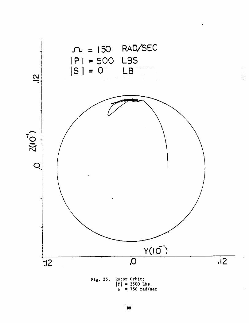
(24-25), illustrate the effects of suddenly applied rotor unbalances. Since
the rotor speed considered is hiah, only • small portion of the clearance
circle is filled. This follows from the fact that due to the rather rapid
changes in orientation of the exciting load, inertia filtering occurs.
Because of this, the rotor is supported by severe velocity gradients which
are only in • close neighborhood. Hence, the pressure gradient generated by
the inlet and outlet ports of the squeeze-film device causes the rotor to
settle in the direction of the low pressure port. Note, as the rotor speed
is decreased, increasingly larger rotor orbits occur. Similar trends occur
as the level of unbalance is increased.
Based on numerous parametric studies involving systems similar to the
foregoing, it was found that all the time integration schemes considered
were stable for situations wherein the fluid underwent only moderate chanKes
in stiffness during the overall cycle. Eventhough • perfusion of harmonics
is introduced by even moderate changes in stiffness (so long as the result-
28

lug spectra are strongly bound by the frequency envelope of the dominate
system frequencies), spurious enersy flow to higher order modes is insigni-
ficant. Specifically, for the implicit scheme, if the choice of tiee step
size is gauged to the dominate hisher order system frequencies, then the
introduction of lower order spectra by the squeeze-fill has little effect on
numerical stability. In contrast, if strong stiffness modulations occur,
the significant amounts of energy flow are introduced in the ever shifting
hisher order modes. This leads to solution instabilities unless ssaller At
are introduced. In this context, the use of the explicit scheme is
advocated over the iuplicit for problems involving strong-to-weak unbalance
loads.
34
9. aX IES
This Section of the report summarizes the third (final) year work on
this grant. This effort vat focused primarily on basic experimental studies
on the orbital vibration characteristics of uncentralized (i.e., no
centering spring) squeeze-film dampers supporting • flexible rotor. The
objectives of this work were (i) to conceive, design and build a new test
apparatus involving two squeeze-film dampers supporting a significantly
flexible rotor, (ii) to perform a wide variety of experimental parametric
studies with the apparatus, and (iii) make fundsmentaI comparison with com-
putational results based on mathematical models and computer algorithms
developed in the previous two phases of this grant. These objectives are
summarized as follows:
• Conceive, design and construct test rig
• Experimental parametric .....
• Comparisons with computational results
The squeeze-film damper (SFD) york summarized in this Section is
presented with considerably more detail in reference [31], the MSME thesis
of R.D. Quinn.
9.1 Review of Some Recent SFD Studies
In 1970, Gunter pubIished an investigation concerning the determination
of the desirable values of rolling element bearing support stiffness and
damping for rigid rotor• [18]. The mathematical model simulated a general
four degree-of-freedom unbalanced rotor mounted on two damped, linearly
flexible supports. The stiffness and damping coefficients could be constant
or speed dependent.
25

In 1973, Giberson [19], of Turbo Research Inc., published • paper ac-
claiming the ability of SFD to stabilize otherwise unstable rotors supported
with journal bearinss. Vhen rotor speed surpasses the threshold of instabi-
lity for the Journal be•rings, 'whirl' amplitude theoretically grows without
bound, possibly destroyins the machine. Pivoted pad journal be•rinss can
stabilize a system by themselves, but 'pivoted pad be•rings supported by SFD
is the arr•nsement with the Breatest ability to stabilize a rotor beatinl
system that uses hydrodynamic bearings'.
In 1974, Mohau and Hahn [20] published • paper on the 'Desisn of SFD
Supports for Rtsid Rotors'. The publication tncIudes• |eneral destsn |uide
for centrally preloaded SFD, supportin8 a risid rotor, mounted on rollins
contact bearinss. The authors also investiBated the transient solutions of
the fully non-linear equations of motion to discover the effect of central
preloadins.
In 1975, Cunningham, FleeinB, and Gunter [21] published an analytical
investisstion on the design of • centrally preloaded $FD for • multimass
flexible rotor mounted on rollinB contact bearings. The paper demonstrates
• technique for the use of sinsle mass, symmetric, flexible rotor analysis
to optimize the stiffness and dampin8 for • symmetric five mass rotor. The
simile mass analysis was taken from a 1972 NASA Report by Kirk and Gunter.
In 1979, Tonneson [22], of the Technical University of Denmark, pub-
lished • study on experimental squeeze-film bearin$ orbits. The purpose of
the investisation vas to compare experimentally measured dampiu| coeffi-
cients with those obtained from simple liuearized theory. Comparisons were
made to both eccentric (offset) and concentric (centralized) damper Journal
orbits.
26
In 1977, Bansal and Hibner [23], of Pratt and Whitney, published •n
'Experimental and Analytlc•1 investigation of (dynamic) SFD Forces Induced
by Offset Circular Whirl Orbits'. In agreement with Tonneson, the authors
suggest that offset orbits •re more realistic for flexible damped supports.
In 1977, Hibner, Bans•l and Buono [24], of Pratt and Whitney, published
• paper on the control of instability for the Intershaft SFD. An earlier
analytical and experimental investigation had shown the existence of an
intershaft viscous damper instability.
In 1979, Hahn [25] published an analytical investigation on the 'Unbal-
ance Beh•vlour of Squeeze File Supported Rigid Rotors'. Equilibrium load
capacity and transuissibillty data for • vide range of operating conditions
are presented for centrally preloaded and unloaded vertical rljld rotors
mounted on rollins element bearings.
In 1979, Vance [26], of Gas Turbine Laboratories, published s review of
rotor dynamics which included the current role of SFD as • solution to
dynamical problems.
In 1979, Hibner and Bansal [27] published an experimental and
theoretical investigation into ;The Effects of Fluid Compressibility on
Viscous Dampers'. The investigation was begun because of the questionable
v•lidlty of the Reynolds equation when c•vit•tlon exists in the squeeze
film. The effects of cavltation could explain why correlations between
theory and experiment for SFDhave been excellent in some cases and poor in
others.
In 1979, Holmes [28], of the University of Sussex, U.[., published a
study on the control of rotor vibration using SFDwlth and without •
parallel flexlble elemen_ The experimental and analytical investiga-
2?

tion includes • general design philosophy.
In 1980 and 1981, Cookson and [ossa [29,30] published the results of
their experJJnental and analytical investigations into the effectiveness of
SFD, without parallel flexible supports, used for supporting flexible
rotors.
9.2 Experimental FaciliCy
The rotor system was designed for use on • Bently-Nevada rotor dynamics
test rig. The rotor was powered by • 1/10 horsepower infinitely controll-
able drive motor capable of driving the test rotor at speeds in excess of
I0,000 RPM. The system included • shaft supported by two sets of preloaded
duplex ball be•rlngs, with each duplex set mounted in an uncentralized SFI).
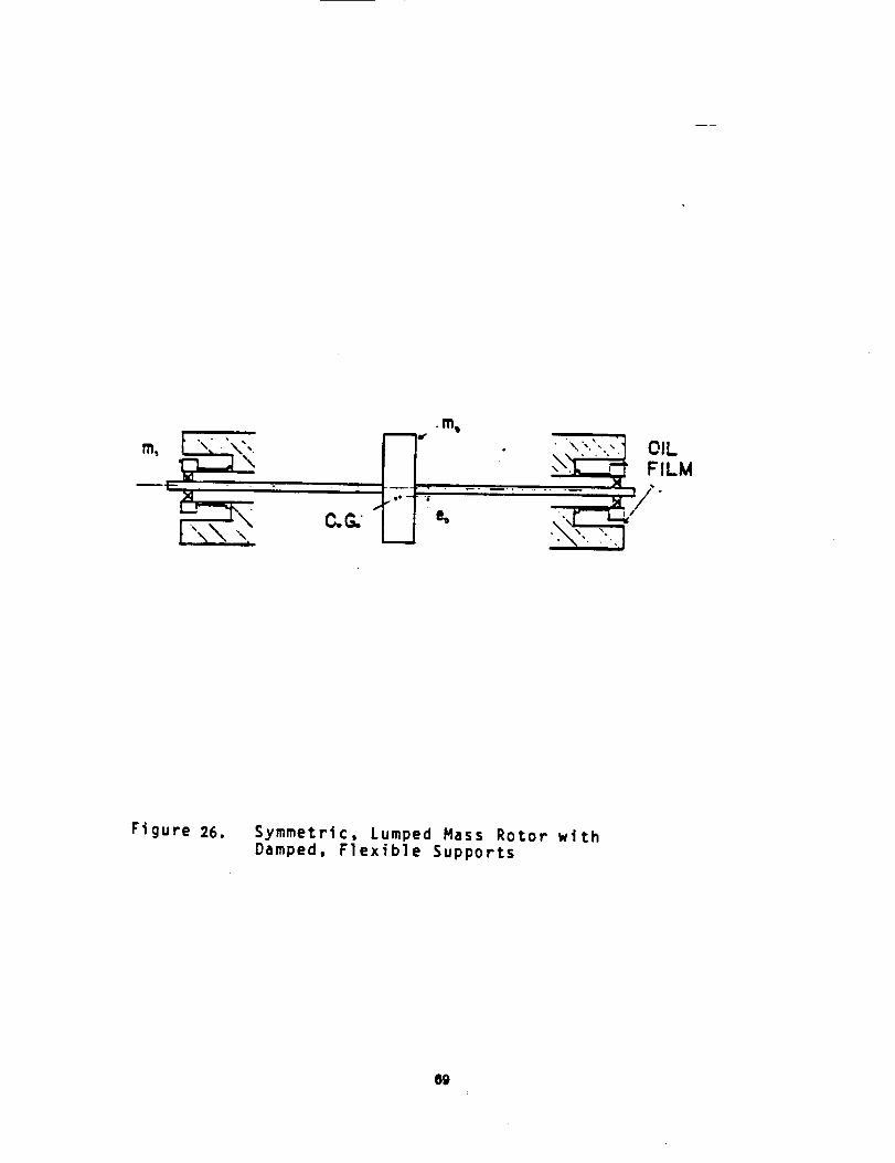
A quill shaft was used to couple the motor and rotor. Rotor discs of
various weights could be located at any position between the bearing
st•tlons (see Figs. 26 and 27).
The preloaded duplex ball bearings provided for stiff bearing-rotor
coupling, so that the bearings could be assumed to be rigid in cozparison
with the rotor and damper film. The preload on the bearings also increased
the rolling friction which decreased the maximum •ttalnable rotor speed and
increased heat generation.
The ball bearing housings which prelosded the duplex bearings acted as
the damper Journals. The damper Journal diameters were 3.3125 inches, the
journal land lengths were .475 inches. So, the length to diameter ratio
was .145, suitably short for • short bearing •pproxlm•tion of the Reynolds
equation to apply.
The damper housings had interchangeable inserts allovin| the radial
clearance for the fluid annulus between the damper bearings and Journal to
Z8

be varied from .004 to 0.20 inches. Se•lin8 betveen the journal and damper
be•tins was accomplished with O-rings in shear. The lateral clearance
between the damper journal end housins yes dimensioned to yield .007 inches
of 'squeeze' on each 0-rims. This •mount of 0-ring squeeze was deterniued
vith • trial and error approach to be near the optlnum, seal ins adequately
under the required oll pressure yet eontributlns mlnimal impedance to
journal motion. Circumferential 8rooves vith outlet ports were located in
the aides of the damper housinss at the edses of the fluid film annulus.
Ports were also provided to check the static oil pressure in the srooves •t
the end of the annulus vith 8 pressure amuse. Also, inlet and outlet ports
were located centrally in the damper inserts and housings at the top and
bottom of the dampers. Flow meterins valves at the outlet ports alloyed for
the end seal or no end seal conditions (or any amount of end leakage or end
pressure desired). On/off valves at the inlet ports alloyed for
circumferential Sroove or port oil feed into the damper annulus. Vith the
appropriate ports closed or open, the damper confijuraiton could be model-
led validly by either the short or Ions bearlns •pproximatlon of the
Reynolds equation. An antirotation pin was threaded through the outside of
the damper housing, through the inserts and into an oversized hole in the
Journal, allowinj journal translation but not rotation (see Fi8. 28). Also,
sea Fiss. 28 throush 32 for more details on the various specially deatsned
damper and other parts.
The steel rotor shaft was 13/16 inches in diameter and 12 inches Ion S
between bearings. The quill shaft used •a the flexible coupling between the
motor and the rotor yam 6 inches long and In 1/8 inch .in diameter. See
reference [16] for the rotor and quill sizing calculations. The flexible
29

.p
coupling eliminated the need for exact alignment of the motor and the two
rotor bearings. Two rotor discs could be located at any position between
the bearings with set screws. Each rotor disc had threaded holes through
its thickness located symmetrically about its outside circumference for the
positioning of balancing weights. The discs were modelled after those that
were furnished wlth the Bently-Nevada test rig. With both discs axially
centered on the shaft, the first flexible node could be excited.
A 8ear pump was used to pump the oll from a heated bath through the
SFD. A metered bypass llne provided a vide range of damper inlet pressure
and flow rate. Heating the SAE 10W oil provided a wide range of damper
fluid viscosity. Copper-Constantan ther_ocouples were used to monitor the
oil inlet and outlet temperatures from the dampers. A thermal veil was used
for monitorins the pressurized inlet temperature.
Vibration detection was accomplished with Bently-Nevada non-contacting
prox4mity displacement transducers. The output of the proxinitors was vlred
into a dijltal vector filter (DVF2) also manufactured by Bently-Nevada. The
DVF2 provided a digital readout of peak to peak displacement, RPM, and phase
angle for location of the rotor's 'high spot' for balancing. Two Tektronix
oscilloscopes, an X-Y-Y plotter, and an HP spectrum analyzer were also
useful aids in studying and recording vibraltoual response. The spectrum
analyzer was expeclally useful for Investisatlu$ nonsynchronous responses.
A five thernocouple input, digital readout potenticaeter was used to nonltor
oil temperature into and out of the SFD. The schematic diagram for this
assembly is shown in FIg. 33.
9.3 Experimental Mctho4 and Objectives
The initial purpose of the experimentation was to verify that the test
80

apparatus could work properly as designed and that operational data could be
taken as desired. Once the system was debugged, the next step was to
conduct • brief par•metric study.
The par•meters that could be contolled for both the 'short' and 'long'
bearing configurations of the damper were as follows:
1) rotor speed
2) unbalance
3) clear•rice
4) oil temperature
5) oil inlet pressure
The second purpose was then to discover the effect on the rotor
system's performance of v•zTing each par•meter while holding the others
constant. Comparisons could then be made with other authors' results and
with • simplified analysis and conclusions made.
The third and final purpose was to recommend possible improvements to
the test equipment and to suggest further work.
Bode plots of peak-to-peak amplitude and phase vs. rotor speed could be
made st both damper locations and at any point along the shaft for both x
and y positions. Also, damper and shaft orbits could be obtained and photo-
graphed for • particular rotor speed. The orbits (oscilloscope tracings)
have • gap in them made by • reference mark useful for phase studies. The
phase mentioned here is the angle between the high spot of the rotor and •
reference mark on the shaft. The meaningful information is the change in
this angle with speed (denoting changes of angles between the high spot and
the unbalance position).
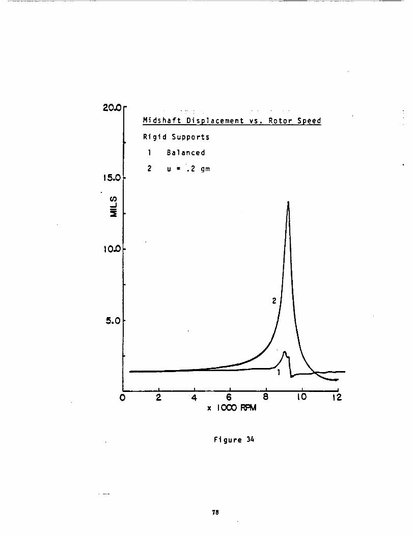
The first task was to balance the rotor after the system was assembled
with the null-clearance inserts in the dampers providing 'rigid' bearing
supports. The DVF2 aided in this endeavor. Fig. 34 shows the nidspan
vibrational response for the balanced rotor. Note that all Bode plots were
made from • location two inches from the nidspan location. Conparing with
the other plot on the sane Figure for • shall unbalance, it can be seen that
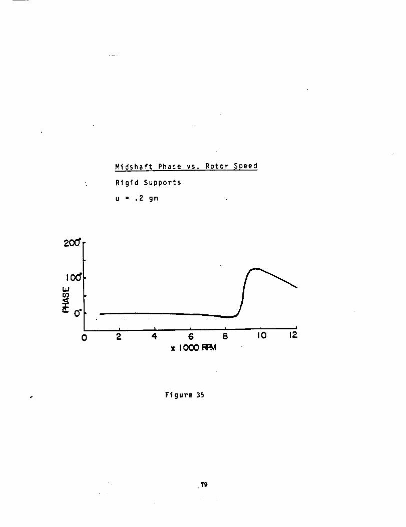
the residual unbalance is small. The sharp critical speed response on Fig.
34 and the abrupt phase change shown on Fig. 35 for • snail unbalance demon-
strates the high stiffness and lack of damping of the ball bearings. The
first critical speed of the rotor can be seen to be about 9200 RPM.
In practice, the four damper mounting screws on each SFD were used to
adjust the O-ring squeeze to seal adequately, yet contribute nlnlnal imped-
ance to journal motion. Shims were then required to restrain the danper
bearings from vibrating relative to their respective housings.
When damper orbit studies were made, the GAP button on the DVF2 was
used to obtain the approximate orbit center coordinates vlthln the clearance
circle. The GAP button provides a measure of the distance between the
proxlneter probes and the rotor. This method was also used to measure the
radius of each clearance circle.
Fig. $6s and b are exanples of typical photographs of the damper and
shaft orbits respectively, taken fron oscilloscope tracings. The rotation
of the shaft is clockwise with respect to all orbits presented in this
paper. Copies of each orbit photograph of interest were reduced to their
proper scale, and placed in the correct position and orientation on drawings
of their particular clearance circle. This was done because knowledge of
the location (offset fron center) of the orbit within the clearance circle
was found to be useful.
82
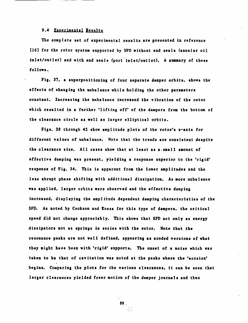
9.4 E_perimental Resu_s
The complete set of experimental results are presented in reference
[16] for the rotor system supported by SFD without end seals (annular oil
inlet/outlet) and with end seals (port inlet/outlet). A summary of these
follows.
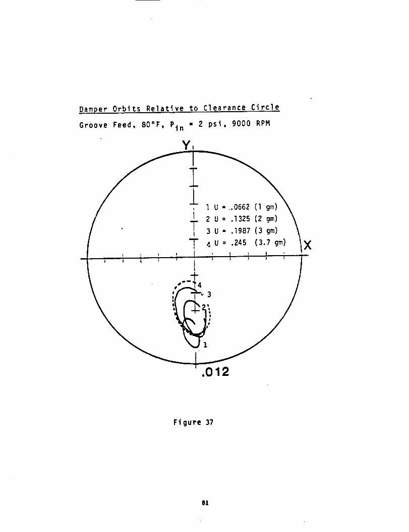
Fig. 37, a superpositioning of four separate damper orbits, shows the
effects of changing the unbalance while holding the other parameters
constant. Increasing the unbalance increased the vibration of the rotor
which resulted in a further 'lifting off' of the dampers from the bottom of
the clearance circle as well as larser e11iptical orbits.
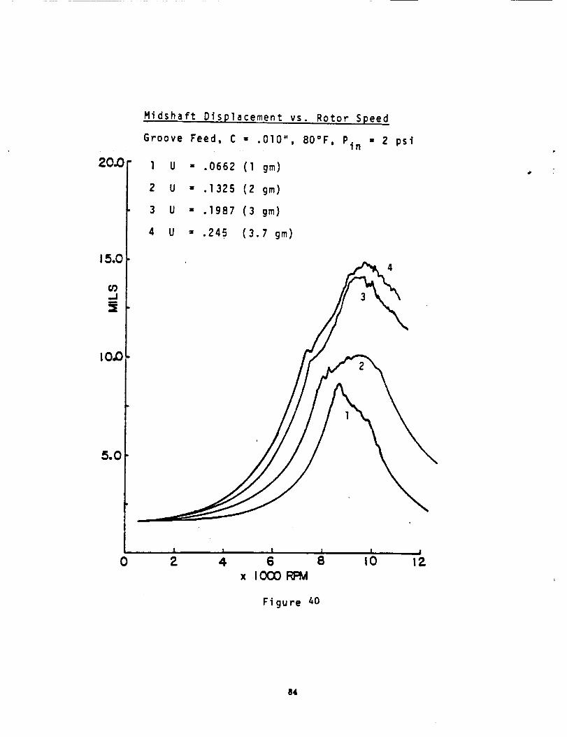
Figs. 38 through 42 show amplitude plots of the rotor's x-axis for
different values of unbalance. Note that the trends are consistent despite
the clearance size. All cases show that st least as a.small amount of
effective damping was present, yielding s response superior to the 'rigid'
response of Fig. 34. This is apparent from the lower amplitudes and the
less abrupt phase shifting with additional dissipation. As more unbalance
was applied, larger orbits were observed and the effective damping
increased, displaying the amplitude dependent damping characteristics of the
SFD. As noted by Cookson and Kossa for this type of dampers, the critical
speed did not change appreciably. This shows that SFD act only as energy
dissipators not as springs in series with the rotor. Note that the
resonance peaks are not veil defined, appearing as eroded versions of what
they might have been with 'rigid' supports. The onset of a noise which was
taken to be that of cavitation was noted at the peaks where the *erosion'
begins. Comparing the plots for the various clearances, it can be seen that
larger clearances yielded freer motion of the damper journals and thus
'softer' dampers. Larger clearances yielded more favorable rotor responses
(for this system).
9.5 ConnarisQp with _ Simvli_ied Comnnter Model
The rotor was modelled using an available code, assuming the rotor to
be ri$id [8]. Of course, the rotor was not timid at the speeds which the
experlmentsl results were obtained. Thus, the damper excitation was not
necessarily the same and direct comparisons could not be made. However,
qualitative comparisons concerning the senerel character of the orbits were
found to be useful. All computed cases presented were run at 10,000 RPM,
vlth 3 |m unbalance and low inlet pressure using a short bearing approxima-
tion of the Reynolds equation.
Considering Fiss. 43, 44, and 45, with increasing viscosity, the
orblt's amplitudes and offsets decreased, showinl the damper to be Srowlng
stiffer. This agrees with the experimental results. Also, as the offset
decreased, the orbits became more circular, which also agrees with
experimental evidence. All of the computer produced orbits (clockwise ro-
tations) are left of center (e.g., see Fig. 44) and approach the center line
(y-axis) with decreasins offset. This is also the general rule for the
experimentally obtained orbits. From this lest comparison it can be seen
that increasing thc cl_rsnce in both cases produced larger orbits and off-
sets and thus a softer damper.
I0. _I_¥ AND CONCLUSIONS
Phase -1 of this work provided the following:
• Overall solution strategy for the seneral en$ine dynamics problem
• Clear definition of where current efforts should be conc6utrated
• A SFD software packase ready for FE implant
Phase -2 of this work provided the followins:
• Methodolosy for implanting SFD element into a |eneral FE code
• Benchmarkins the SFD/ADINA combination
• Numerous relevant example-problem solutions
Phase -3 of this work provided the followlns:
• Conception, desisn and construction of • SFD/flexible rotor test ris
• The results of basic experimental parametric studies
• Comparisons with computed results and results of previous
investisators
It is concluded that |eneral ensine dynamic analyses as a standard
de•Jan-study computational tool is readily available, practical and hishly
desirable for the prediction and understandins of complex enslne dynamic
behavior. Improved definition of ensine dynamic response viii likely
provide valuable information and insishts leadins to reduced maintenance and
overhaul costs on exlstins ensine coufisurations. Furthermore, application
of advanced ensine dynamic simulation methods will provide • considerable
cost reduction in the development of new eujine deal|us by eliminatin$ some
of the trial-and-error process done with enslne hardware development.
Clearly, the field of aircraft enjine dynamics is presently in •
position where there is both a need for subst•ntlal advances and feasible
means by which such advances can be accomplished. The necessary approach
and methods have been developed, proven and demonstrated by this work.
35
ACKNOWLEDGEMENTS
The original idea for this work came from Dr. C.C. Chamis, the NASA
Technical Officer and monitor of this grant. The authors greatly appreciate
not only his inspired exposure of this general problem area but also his
helpful suggestions and continued encouragement for all the investigators
working on the grant.
Ve also appreciate the opportunity provided byNASA in its sponsorship
of this grant. Not only have important methods and results been generated
by this work, but also the professional learning experience for the
principal investigators and involved graduate students has been qnite signi-
ficant. All of these individuals have gained much toward their continued
professional grcrwth and increased knowledge about an important aerospace
field.
86

REFERENCES
l.
.
.
.
u
.
u
10.
11.
12.
13.
D.G. Fertis, Dynamics and Vibrations j_ Structures, Wiley, New York,1973.
D.H. Hibner, 'Dynamic Response of Viscous-Damped Multi-Shaft JetEngines', AIAA 3.urns of Aircraft, Vol. 12, 1975, pp. 305-312.
M.L. Adams, _Nonlinear Dynamics of Flexible Multi-Bearing Rotors',Journ. of Sound and Vibr., Vol. 71, No. I, 1980, pp. 129-144.
T. Belytschko, 'Nonlinear Analyses-Descriptions and Numerical Stabi-lity', Comvuter proRrams in Shock an..__dVibration, ed. W. Pilkey andB. Pilkey, Shock and Vibration Information Center, Washington, D.C.,
1975, p. 537.
O.D. Zienkiewicz, The Fipite E|emcnt Method, McGraw Hill, London, 1977.
C.A. Felippa, and £.C. Park, 'Direct Time Integration Methods in Non-linear Structural Dynamics', presented at FENOMECH, Upjversitv ofStuttRart, 1978.
Structural Mechanics Computer P_0zrams, ed. by ][. Pilkey, £. Saczalski,and H. Schaeffer, University Press of Virginia, Charlottesville, 197S.
M.L. Adams, 3. Pad.van, and D.G. Fertis, 'Finite Elements for Rotor/
Stator Interactive Forces in General Engine Dynamic Simulation, Part I:
Development of Bearing Damper Element', NASA Re___ on Grant NSG-3283,October 1980.
J.P. O'Donoghue, P.R, Koch, and CJ. Booke, 'Approximate Short BearingAnalysis and Experimental Results Obtained Using Plastic Bearing Liners',Proc. Institute of Mech. Entineers, Vol. 194, 1969, pp. 190-196.
S.M. Rhode, and D.F. Li, 'A Generalized Short Bearing Theory', ASME
Journ. of L_br|fation Techn., Vol. 102, No. 3, 1980, pp. 278-282.
L.E. Barrett, P.E. Allaire, and EJ. Gunter, 'A Finite Length Bearing
Correction Factor for Short Bearing Theory', ASME _ourn..__Techn., Vol. 102. No. 3, 1980, pp. 283-290.
V. Castelli, and W. Shapiro, 'Improved Method for Numerical Solutionsof the General Incompressible Fluid Film Lubrication Problem', ASME
_ourn. of Lpbrication Techn., Vol. 89, No. 2, 1967, pp. 211-218.
M.L. Adams, J. Pad.van, and D.G. Fertis, 'Engine Dynamic Analysis withGeneral Nonlinear Finite-Element Codes, Part I: Overall Approach and
Development of Bearing Damper Element', Trans. ASME u_ ofinm for Power, Vol. 104, July 1982, pp. 586-593.
g7

14.
15.
J. Padovan, M.L. Adams, D.G, Fertis, I. Zeid, and P. Lam, 'Engine Dyna-mic Analysis with General Nonlinear Finite Element Codes, Part 2:Bearing Element Implementation, Overall Numerical Characteristics andBenclunarking', ASME_ No. 82-GT-292. Presented at 1982 Gas TurbineConference.
J. Padovan, M' Ad|ms, J. Fertis' I. Zeid, and_P. La_ 'Engine Dynamic
Analysis with General Nonlinear Finite Element Codes, Part II - BearingElement Implementaiton, Overall Numerical Characteristics andBenclunarklng', NASA Rgpo_t on Grant NSG-_283, October 1981.
16. N.M. Nemeark, 'A Method of Computation for Structural Dynamics', J.Mech. Div., ASCE, 85, EM3, 67-94 (1959).
17. E.L. Wilson, 'A Computer Program for the Dynamic Stress Analysis ofUnderground Structures', Report No. SESM68-1, Dept. of Civil Engineer-ing, University of C_lifornia, Berkeley (1968).
18. EJ. Gunter, 'Influences of Flexibly Mounted Rolling Element Bearingson Rotor Response, Part I - Linear Analysis', Journ. of LubricationTechn., Vol. 92, Series E, No. 1, January 1970, pp. $9-69.
19. M. F. Giberson, _aming Rotor Whirl with Film-Damper Bearings', MachineDesian, Vol. 45, No. 7, March 22, 1973, pp. 176-181.
20. S. Mohan and EJ. Hahn, 'Design of Squeeze Film Damper Supports forRigid Rotors', J. Emir. for Ind., Trans. ASME, Series B, Vol. 96,1974, pp. 976-982.
71. R.E. Cunningham, D.P. Fleming, snd E.J. Gunter, 'Design of a Squeezefilm Damper for a MultJJnass Flexible Rotor', 3, E_zr_ for Ind., Trans.
ASME, B97 (4), pp. 1383-1389 (1975).
22. J. Tonnesen, 'Experimental Squeeze Bearing Orbit Studios', $. Emir.
for lad., Trans. ASME, B97 (4), pp. 83-95.
23. P.N. Bansal and DJ. Bibner, 'Experimental and Analytical
Investigation of Squeeze Film Bearing Damper Forces Induced by OffsetCircular Whirl Orbits', $ourn. of Mech. De s ira, Vol. 100, No. 3, July1978, pp. 549-557.
24. D.H. Hibner, P.M. Bansal, and D.F. Buono, 'Analysis and Experimental
Investigation of the Stability of Intershaft Squeeze Film Dampers -Part 2: Control of Instability', 3ourn. of Mech. _, Vol. 100, No.
3, July 1978, pp, 558-$62.
25. EJ. Hahn, 'Unbalance Behavior of Squeeze Film Supported Rigid Rotors'.Journ. of Mech. Desitn, Vo]. 100, No. $, July 1978, pp. 176-188.
26. J. M. Vance, 'A Current Review of Rotordynamics Problems in High SpeedLightweight Turbomachinery and Power Shafting', Proc. of the Conference
on the Stability and Dynamic Response of Rotors with Squeeze FilmBearings, University of Virzinia Charlottesville, May 1979, pp. 7-19.
$8
27.
28.
29.
30.
31.
D_. Hibner and P.N. Bansal, 'Effects of Fluid Compressibility on
Viscous Damper Characteristics', Proc. of the Conference on theStability and Dynamic Response of Rotors with Squeeze Film Bearings',
University of _, Charlottesville, May 1979, pp. 116-132.
R. Holmes, _l'he Control of Rotor Vibration Usin| Squeeze Film Dampers',Proc. of the Conference on the Stability and Dynamic Response of Rotors
with Squeeze Film Bearlnss', University of V_rlinia, Charlottesville,
May 1979, pp. 53-72
B.A. Cookson and S.S. Kossa, 'The Effectiveness of Squeeze-Film Damper
Bearinss Supportins Flexible Rotors vithout a Centralizin| Sprin|',
Int. J. Mech. Sci., Vol. 22, May 1980, pp. 313-324.
R.A. Cookson And S.S. Kossa, 'The Vibration Isolatlns Properties of Un-
centralized Squeeze-Film Damper Bearinss Supporting a Flexible Rotor',ASME International Gas Turbine Conference, Houston, Texas, March 1981.
R.D. Quinn, 'Experimental Study of Uncentralized Squeeze Film Dampers',M.S. Thesis, The University of Akron, Akron, Ohio, lanuary 1984, 117 p.
$9
NO_N_ATIYRE
C
D
e
F X
Fy
h
L
P
R
t
X
I
Y
X
P
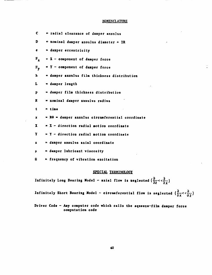
= radial clearance of damper annulus
= nominal damper annulus diameter = 2R
= damper eccentricity
X - component of damper force
= Y - component of damper force
= damper annulus film thickness distribution
= damper lenjth
damper film thickness distribution
nominal damper annulus radius
time
= Re s damper annulus circumferential coordinate
X - direction radial motion coordinate
= Y - direction radial motion coordinate
= damper annulus axial coordinate
= damper lubricant viscosity
= frequency of vibration excitation
SPECIAL TERMINOLOG_
Infinitely Lon. Beaztn. Model - axial flov is me.letted (_-=-<<_---)ol OX
Infinitely Short Beartn, Model - circumferential flow is neglected (_<<_'_Z)
Driver Code - Any computer code which calla the squeeze-film damper forcecomputation code
40
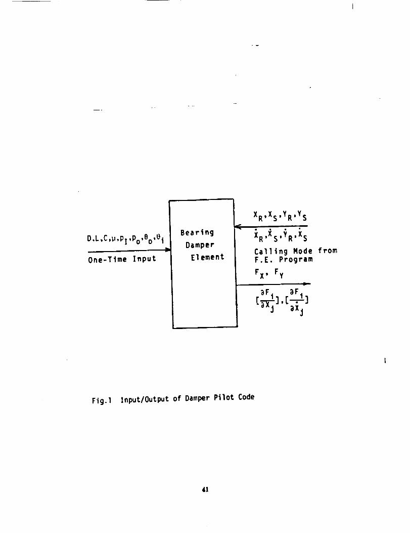
D.L,C,_,PI 'Po'eo'Ot
One-Ttme Input
Bearing
Damper
Element
XR,Xs,YR,Y $
XR,Xs,YR,Xs
Calling Mode fromF.E. Program
FX, Fy
_FI [_FI][_-_j]' _xl
Fig.1 Input/Output of Damper Pllot (:ode
41

_
x,j- !/////
Fig. 2 Inertial coordinates
42

c =o,olo_
FEEDP_ HOLE
DRAINPo HOLE
I
0I--
qlP
.'r
Fig. 3 A typical aircraft engine damper configuration
4s

O-RING SEALS
Fig. 4(a) Configuration frequently used in military applications
44

PISTON -RINGm • t_mw_mmmm, rmmllmlmmmD o
SEALS
Fig. 4(b) Configuration frequently used in conlnercial applications
¢5

46

o
(a) e/c=O.05
(b) e/c=0.20
Figure 6 Pressure distribution in circumferential direction mnd time
of one cycle of circular orbit(long-bearing solution).
41
"I )

(c) e/c=0.60
(d) e/c-0.95
Figure 6 Pressure distribution in circumferential direction and time
(Cont'd) of one cycle of circular orbit (long-bearing solution).

o
(a) elc-O.05
!
"c
4_
(b)
\
\o (I
e/c-0.20
Figure 7 Pressure distribution in circumferential direction and time
of one cycle of circular orbit (short-bearing solution).
49
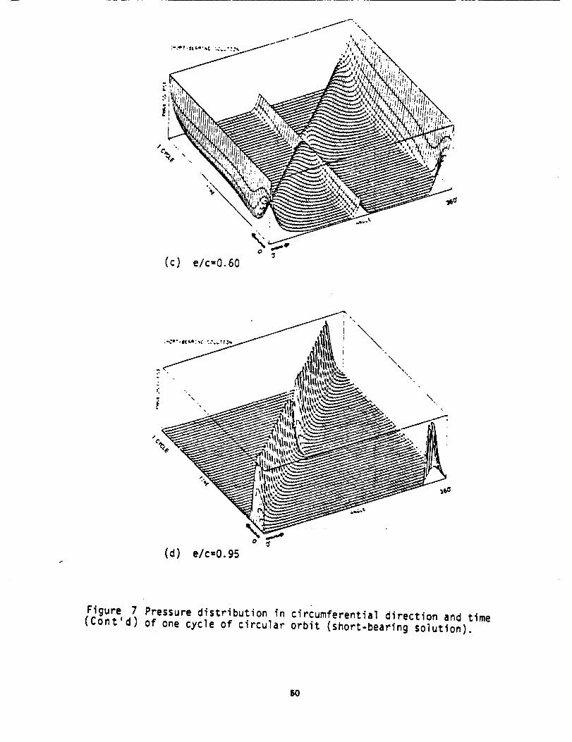
\
(c) e/c=0.60
o
(d) elc=0.95
Figure 7 Pressure distribution in circumferential direction and time
(Cont'd) of one cycle of circular orbit (short-bearing solution).
8o
STATOR (M2)
KX
ROTOR (MI)
° °,- ° o;
OIL FILM
P, =5 5 Ps_
_igure 8Simple 2-mass,4-degree of freedom. Test case
(Same damper parameters as on page ZS)
81
?
(a)
(,_,_)
Rotor and stator orbits
J
(b)
clearance circle
1" _
\
JfI i
/_,./s)
Rotor orbit relative to stator
(clearance circle shown)
Fig.9 Nonlinear dynamic transient of simple 4 DOE system(See Fig.B)
IFl=lO0 Ibs'_=150 rad/sec,H1=M2=500 Ibs,Kx=Ky=116000 Ibs/in.
52

(a)
• _' • /e " ;#
Rotor and stator orbits
(b)
cl earance
/ '\
: 1if/
circle
(_v.'/,)
s#
Rotor orbit relative to stator(clearance ctrcle shown)
Fig.lO Nonlinear dynamic transient of slmple 4 DOE system(See. Fig 8))Fl=ZO0 lbs',_,=150 rad/sec,t.ll=H2=500 lbs,Kx=Ky=116000 lbs/in.
58

/,/_,.X
y .
'LIe -4, " ._ @
(a) Rotor and stator orbits
?
[
/l
\\
\... /
_. (w_,/,)¢ T -- , ....... ,
-t_ . _ .=4 ._ ,_ i_
(b)
clearance circle
/
Rotor orbit relative to stator
(clearance circle shown)
Fig.ll Nonlinear dynamic transient of simple 4 DOE system(See. Fig.B}
IFI=300 Ibs'_=lbO rad/sec,ttl=M2=500 Ibs,Kx=Ky-116000 Ibs/in.
5¢
L_,./,)
P@ 4 i@ ' #l
(a) Rotor and stator orbits
clearance ctrclei i
(,_,'/s ;
(b) Rotor orbit relatlve to stator(clearance circle shown)
Fig.12 Nonlinear dynamic transient of slmple 4 DOE system(See. Fig.B)JF]=500 Ibs'_=150 rad/sec,T_]=M2=500 Ibs,Kx=Ky-]16000 Ibs/in.
55
(a)
{,_,/s/
-'@. E ¢
Rotor and stator orbits
1 clearance circle
i' )(_,-_,)
9
(b) Rotor orbit relative to stator
(clearance circle shown)
Fig.13 Nonlinear dynamic transient of slmple 4 DOE system
IFl=10001bs'_=150 rad/sec,t.11=_12=500 Ibs,Kx=Ky=116000 Ibs/in
5o
S
SOUEE/EFILM
= 15PSi P(t)
I
.I[,SEC .4SECSHOC ", t_OAD IMBALANCE LCA[
Fig. 14. Single Bearing Model
57

II
!!
i!i
JIIi
i
i
J
!
_o_- I
.J
N i
LiiJ
I-_- 150IPI: 2OISl: 0
RAC/SEC
LBS
LB
.... IPII
I
!
II
!
I:WII,-
-ZY(IO )
Fig. 15. Rotor Displacement;
IPl- 20 Zbs.
58

5
JI
If
O4O_
m
!
O
U "
J
/
/
= 150 RAD/S E CIPI= 20 LBSISl = 0 LB
!
II
0.!,If
.0
¥( I(_ 2)
1"! !
.,5
Fig. 16. Stator Displacement;IPl"20Is-.
59
r_ =150 RAD/SECIPl= 20 LBS
_.j ISl = o LB _o - BENCHMARK [7]
qJ
\
i
,IPI JI
I
I
_1 ' Y(JO-')-.o8 ' :o .OS
FiR. 17. Rotor Orbit; JPJ - 20 lbs.
60

4'
ip
!
!,
i
i|
!
!I
.I
t,q
L'T= 150 RAD/SEC
IPI=2 5oo LBS
ISl=O LB
o._ /,,." ./ ,:?- . -'-_,-,,,_\ ,..,,.7, r /"" \ , '.'.--'// - .. ...-----_-___ ,,,.. ,\\,L/ ;,' /7 ,.. . \,G, ,,,,,t / / / / / .'/ \ " '-- '_ \ , ' '," ' I , " d" 1_. _ '_ _ I_ \ , _ ', ",
: ' i ' f" / 1 ,_ , i _ _ . \ " " ',, _ I ; i / _t / _,., I ", I \ _ ',. . _ '
; i " ! I il '.X * * I , _ ._ \ ',
i_ I // I i i "J,, ; / i _! I ;_,_ '. ! I / I : ,. - .,' / i : _ _ # __ _ I i I . : _ / / I : ,_' 'I f " , i : _ , I lx I '_' '
q-_ !, \ \\ \ _I ,..z / .I/ , ,: ,: ,,- \, ',.'.,k, ",...x, ....: ,.," //i i/,/
_ ..
Y
Fi_. 18. Rotor Displacement ;
Ipl-2soozb,.
Ol

o."I!
lI
_0 .4Illll
i!
i
g_
I
I
|
i!I
-it
i
Ir
/
2
z'_ = 150 RAD/S EC
IPI =25OO LBSI SI - I000 LBS
I
I I I I
.0 .O8
Fig. ]9. Stator Displacement;
IPi-25ooIb_.
83

/I
i
/50 R,CD/SEC
= I000 LBS
1",4
i!
O'
I
!
I'ii
1II
/
FIGURE .06.14 ROTOR .04
(SEE FIGD.ISPLACEMENT6.! )
F_g. 20. ROtor Orbit;
IPI- 2soosbs.

A_El EI_ Ms:M__5OQLBSL _ L--_I M =IO00LBS
'- ' - ' _ : 4_51NCHE = 50 ._I06PSI _ I =465.INCH _ L
_ROLLERNBEARI
D
M
M S
IPiI
!
I
±
SHAFTING
MSFDBSQUEEZE
F/L M DAMPE R
Fig. 21. Multibearlng Model

J
q
Ii
IOO_O:"i
I
_ji
U iI
0.4
li
•._ = 7 50 RAD/SECIPI =2500 LBSISI = 0 LB
Y(ad')!
-.08 ' :0 .08
Fig. 22. Rotor Orbit;
IPI = 5o0 ibs.

I
I
1i
!ii
t
CxJ_
i
o.!iII
!
I
I
I
I4
JI
!m
= 150 RAD/SECIPI = 25OO LBSISI - o LB
Y(IG')De o ' '- • .08
Fig. 23. Rotor Orbit;IPT- 2sooIb_.

!
Ji
i
l
iI
ii!I
i
OJ:
l
J
i
Iz
bN:
.J
)/
_=75o RAD/SECP =2500 LBS
S=O LB
Fig. 2&. Rotor Displacement ;
IPI " 2500 ibs.- 750 rad/sec
6T
C_d
= 150 RAD/SEC
P 5000 LBSIs'l: :
.12
\
I
:o .12
Flg. 25. Rotor Orblt;
IPl" 2sooLbs.= 750 rad/sec
68
\
_J
OILFILM
Figure 26. Symmetric, Lumped Mass Rotor withDamped, Flexible Supports
69
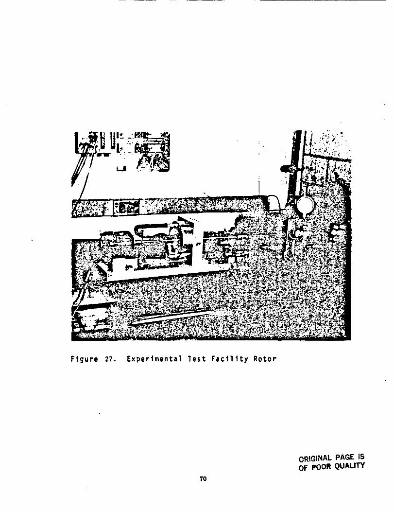
Figure 27. Experimental lest Facility Rotor
ORIGINAL PAGE 15OF POOR QUALITY
70
| I
I !
- I II
I I
i I
I J
I II I
I , I
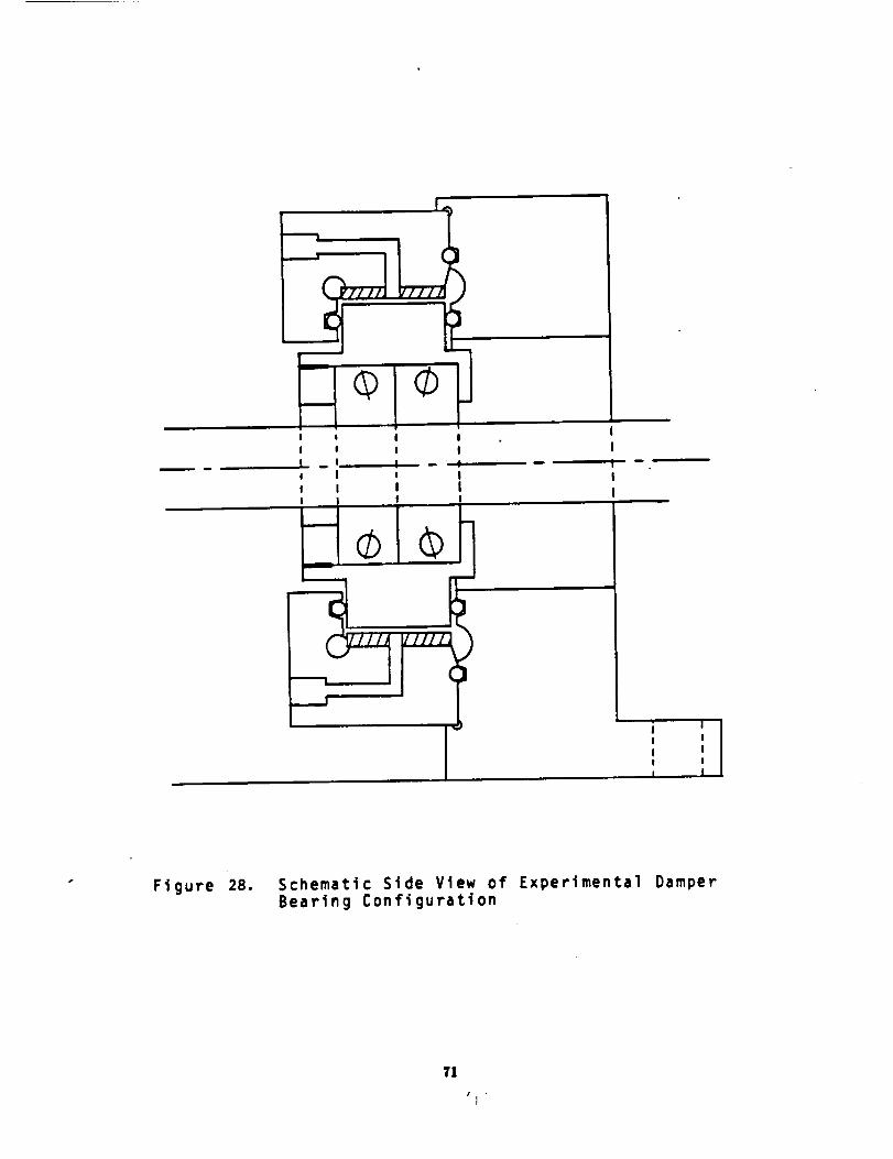
Ftgure 28. Schematic Side Vtew of Experimental DamperBearing Configuration

!/ 8"
PlP£
i/8" PIPE
R I " ]-5/32"
R= - ]-]9/32"
R 3 " 2-5/8"
]/2 Scale
Aluminum
2 Reqd.
Fig. 29. Damper Bearing
72

i!
I .7 5"
I'
1/2 Scale
Aluminum
2 Reqd.
Fig. 30. Damper Journal/Bearlng Holder
T$
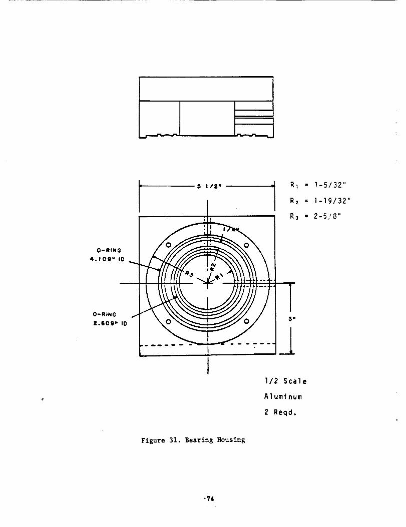
O-RING
4. t09" ID
I/2 Scale
Aluminum
2 Reqd.
Figure 31. Bearing Housing
-74
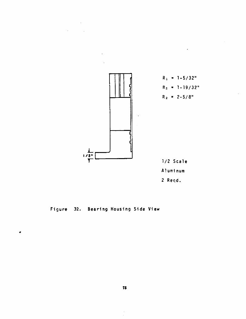
Rl " I-5/32"
R2 " l-lg/32"
R2 " 2-5/8"
I/2 Scale
Aluminum
2 Reqd.
Figure 32. Bearing Housing Side View

2 3 a
1 2 3 4
0 _ E] a_ _o_-/_ su'-_',Y - -2 _--I 2 3 4 I
_ cp 9 _ ¢.o_o I
CH 1
-o1, IN CH._
i
o I OUT C, i 1, I
0 i tic limp 0 I
-oJoo0_...uII
corn 0 I
-i8 V dc@
ext K _ C _-
dc RPk* 0_4__
DVF2
Figure 33. Wirlng Schematic
T6

43 2 7
ext
int _
in
i
, 1
] ex! in_ ;
I G II,com J
6 5
I
PLOTTER 1
X Yl Y2 ;hi Io hi Io hi Io
SPECTRUM ANALYZER 1A con" B con_
T ° T °
Figure 33. W_r|ng Schematic (Continued)
7?
20J)
15.0
(y).Ju
IOZ)
5.0
0
Midshaft Displacement vs. Rotor
Rigld Supports
1 Balanced
2 u =_.2 gm
2
2! I , I
4 6 8x 1002) RF_
Speed
!
I0I
IZ
Ftgure 34
78
Midshaft Phase vs. Rotor Speed
Rigid Supports
u - .2 gm
20¢
0I !
2 4| |
6 8
x I000 R_I
I0 12
Figure 35
.79

a .
" _ '_ _:_'_ NB._-I_L,._ .4_" k _
Oamber Orbit, Groove Inlet, c • 01" 80°F go00 RPAt,lO psi, 3.0 gm unbalance, 1 MIL/DZV.
_'_ "'g._ _." .,,r _ ,,
b. Shaft Orbit• same as above except 2 psi, 2.5 HIL/DIV.
Figure 36. Photographs of Oscilllscope Tracings of Damperand Shaft Orblts
80 _-
ORIGINAL PAGE IS
OF POOR QUALITY
Damper Orbits Relative to Clearance Circle
Groove Feed, 80°F, Pin = 2 psi, 9000 RPM
Y,
I I ! !
| I
!±, l U =..0662 (l gm)
1 2 U = .1325 (2 am)m
I 3 u = .19B7(3 gm)l
(3.7 gm), _ U = .245
iI
I
X
.012
Figure 37
8!

2O.O
Midshaft Displacement vs. Rotor Speed
Groove Feed, C = .020 °, 80 °F, Pin
1 U = .0231 (l gin)
2 U - .0662 (2 gm)
3 U = .0993 (3 gin)
= 2 psi
15.0
0 2 4
!
6 8x IOCO_
I J
|0 IZ
Figure 38
82

Midshaft Phase vs. Rotor Speed
Groove Feed, 80°F, C = 010" Pi
1 U = .0662 (l gm)
2 U - .1987 (3 gm)
• 2 psi
2od
Icd
0
I
i i J i i I
2 4 6 8 I0 12
x I000 R:M
Figure 39
85
20.0
15.0
¢0.Jm
I0.0
5.0
0
Midshaft Displacement vs. Rotor Speed
Groove Feed, C - 010" 80°F P - 2 psi• ' ' in
1
2
3
4 U
U • .0662 (1 gm)
U " .1325 (2 gm)
U - .1987 (3 gm)
• .245 (3.7 gm)
l I I I
2 4 6 8x I OCO RRul
Figure 40
| .
I0!
12
84
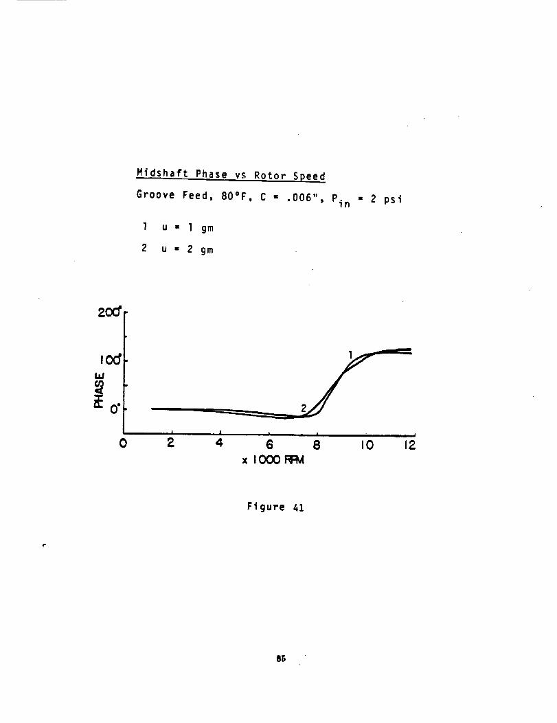
Midshaft Phase vs Rotor Speed
Groove Feed, 80°F, C - 006" Pin• , = 2 psi
l u = 1 gm
2 u = 2 gm
2od
lod
0• , | ,I, _ I
2 4 6 8 I0
x I000 R:M
| !
12
Figure 41
85

20J)
I5.0
o'}.J
I0.0
5.0
0
Midshaft Displacement vs. Rotor Speed
Groove Feed, C - 006" 80*F P - 2 psi• ' ' in
1 U = .0555 (.5 gm)
2 U - .Ill (l.O gm)
3 U • .222 (2.0 gm)
4 U = .333 ('3.0 gm)
I " I I I , I
Z 4 6 8 |0 %Zx 1000 RI:_
Figure 42
80
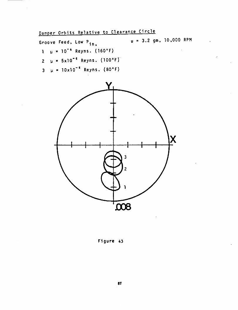
Damper Orbits Relative to Clearance Circle
u = 3.2 gm, lO,O00 RPMGroove Feed, Low Pin,
1 u I I0 "_ Reyns. (160°F)
2 _ , 5xlO "6 Reyns. (IO0°F)
3 u , 10xlO -6 Reyns. (80°F)
Y
FIgure 43
87
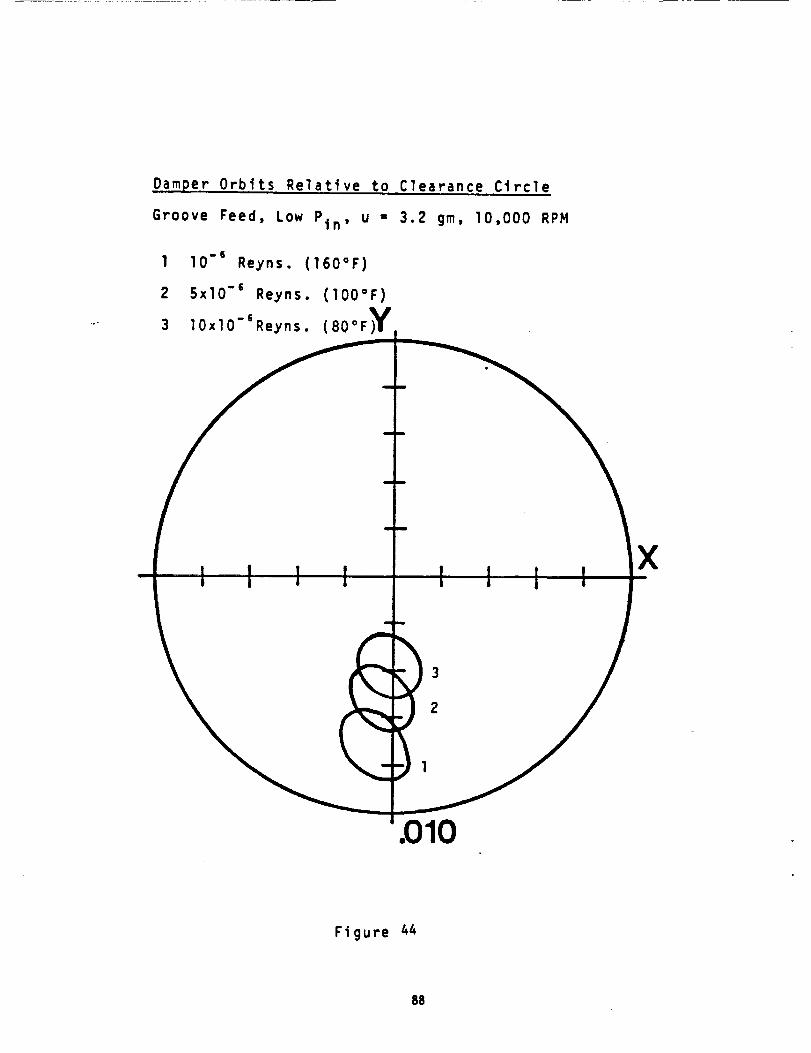
Damper Orbits Relative to Clearance Circle
Groove Feed, Low Pin' u - 3.2 gm, 10,000 RPH
1 10 "s Reyns. (160°F)
2 5x10 "s Re vns. (IO0°F)
3 lOxlO'SReyns. (8OOFy
.010
Fi gure 44
88

Damper Orbit Relative to Clearance Circle
Groove Feed, Low Pin' u = 3.2 gm, 10,000 RPM
I I0 "s Reyns. (160°F)
2 10xlO'* Reyns. (80°F)
Y
.020
Figure 45
89
FormApprovedREPORT DOCUMENTATION PAGE OMBNo 0704-0188
ng _ mw_zr_ I_ oma _, _ OOml_..)rig _ rw_k_g 1he ¢_Slc.l_¢__ _¢_m_n. aer_ _r_'_ntm rqwosr_ 1_ buro_ ems_-_e of _y _f_r _ _ m_
of imom'_._ofl, includ[n_|uOg_tio_l |_ mOUClr_this bun_n., to Wash_glO_ I.JdMclquatlem_'vk_l, Dkeclorll_lpfo_ kffon'n_ion Oper_ a."KIR4T_o_s,1245 J_ffec&o_gnway, aune 1204, Arlington.VA _2202..4302, and to the Offioeof Mamaoem_n[and Bu_g4d,Pape_vork R4ducfion_'to_d (O704-01U). Washlr_to_, DC 20503.
1. AGENCY USE ONLY (Leat,e b/ank) 12. REPORT DATE [ ,. REPORT TYPE AND DATES COVEREDOctober 1991 Final Contractor Report
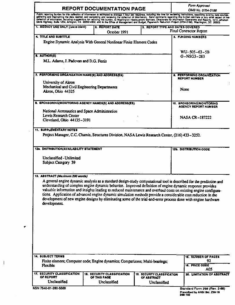
4. TITLE AND SUBTITLE 6. FUNDING NUMBERS
Engine Dynamic Analysis With General Nonlinear Finite Element Codes
_. AUTHOR(S)
M.L. Adams,J. PadovanandD.G. ]Fcz_
7. PERFORMINGORGANIZATIONNAME(S)ANDADDRESS(ES)
University of AkronMechanical and Civil Engineering DepanznentsAkron, Okio 44325
t BPONSORING_ONITORINGAGENCYNAMES(S)ANDADDRESS(ES)
National Aeronautics and Space AdminiswationLewis Research CenterCleveland, Ohio 44135-3191
WU-505-63-5BG-NSG3-283
8. PERFORMING ORGANIZATIONREPORT NUMBER
None
10. SPONSORING/MO NITORINGAGENCY REPORT NUMBER
NASA CR-187222
11. SUPPLEMENTARYNOTES
Project Manager, C.C. Chamis, Structures Division, NASA Lewis R_h Center, (216) 433-3252.
_ BSTmBUTION/AV_UL_ILrrYSTATEmNT
Unclassified -Unlimited
Subject Category 39
12b. DISTRIBUTION CODE
13. ABSTRACT (Maximum 200 worda)
A general engine dynamic analysis as a standard design-study computational tool is described for the prediction andunderstanding of complex engine dynamic behavior. Improved definition of engine dynamic response providesvaluable information and insights leading to reduced maintenance and overhaul costs on existing engine configura-tions. Application of advanced engine dynamic simulation methods provide a considerable cost reduction in Ihedevelopment of new engine designs by eliminating some of the lrial-and-error process done with engine hardwaredevelopment
14. SUBJECT TERMS
Finite element; Computercode;Engine dynamics;Comparisons;Multi-bearings;Flexible
t7. SECURITYoFREPORTunc|a_flP.,dCLASSIFICATION[ 11. i 15.
NSN7540-01-280-5500
SECURITY CLASSIFICATIONOF THIS PAGE
Unclassified
SECURn'Y CLASSIFICATIONOF ABmAc'r
Unclassified
lB. NUMBER OF PAGES
921l. PRICE CODE
A0520. UMITATION OF ABSTRACT
S1andsrd Form 298 (Rev. 2-89)
I_'esctl:md by ANSI _td. Z39-18298-102


