Eng 17(rev-1) Interpretations (pgs 1-42) - NLGA
15
5 NATIONAL GRADING RULE FOR SOFTWOOD DIMENSION LUMBER Approved November 4, 2004 1.0 GENERAL The limiting provisions of the National Grading Rule are quite specific in delineating the characteristics permitted. Because lumber is manufactured from trees which have developed naturally and responsively to their environment and every piece is different it is not possible to anticipate in a grade description all of the possible combinations or types of characteristics which a grader will encounter. These National Grading Rule Interpretations provide additional information to the grader/inspector in the application of the National Grading Rule. These interpretations have been approved by the National Grading Rule Committee and shall be considered a mandatory part of the National Grading Rule. All measurements are based on actual size unless otherwise specified except splits and warp are based on nominal. The limitations on knot sizes and other characteristics governing strength shall not be exceeded. 1.1 BARK AND PITCH POCKETS Bark or pitch pockets are not restricted as to number. 1.2 BEVEL SAWING Limited on the basis of equivalent loss of wood from wane. 1.3 CELL COLLAPSE Cell collapse shall be evaluated as either wane or skip. 1.4 CHIP AND SAW CHANNELS (RABBETED EDGE) Is limited on a basis of wane except in those instances in which the depth or width of the cut exceeds the full length wane provisions, the limitation shall be on a basis of equivalent loss of wood from maximum natural wane. PART 1 1 NGR INTERPRETATIONS
Transcript of Eng 17(rev-1) Interpretations (pgs 1-42) - NLGA
5
NATIONAL GRADING RULE FOR SOFTWOOD DIMENSION LUMBER
Approved November 4, 2004
1.0 GENERAL The limiting provisions of the National Grading Rule are quite specifi c in delineating the characteristics permitted. Because lumber is manufactured from trees which have developed naturally and responsively to their environment and every piece is different it is not possible to anticipate in a grade description all of the possible combinations or types of characteristics which a grader will encounter. These National Grading Rule Interpretations provide additional information to the grader/inspector in the application of the National Grading Rule. These interpretations have been approved by the National Grading Rule Committee and shall be considered a mandatory part of the National Grading Rule. All measurements are based on actual size unless otherwise specifi ed except splits and warp are based on nominal. The limitations on knot sizes and other characteristics governing strength shall not be exceeded.
1.1 BARK AND PITCH POCKETSBark or pitch pockets are not restricted as to number.
1.2 BEVEL SAWINGLimited on the basis of equivalent loss of wood from wane.
1.3 CELL COLLAPSECell collapse shall be evaluated as either wane or skip.
1.4 CHIP AND SAW CHANNELS (RABBETED EDGE) Is limited on a basis of wane except in those instances in which the depth or width of the cut exceeds the full length wane provisions, the limitation shall be on a basis of equivalent loss of wood from maximum natural wane.
PART 1
1
NGR INTERPRETATIONS

6
1.5 COMPRESSION WOOD AND TIMBER BREAKS Separations resulting from seasoning which occur in allowable bands of compression wood shall not be evaluated as timber breaks or compression failures.Compression wood shall be limited in effect to other appearance or strength reducing characteristics permitted in the grade.Compression failures and timber breaks are permitted only in the grades of Standard, NO. 3, Utility and Stud. They are limited to the size of the allowable knot hole.
1.6 HOLES
1.6. 1 Insect Holes: Pin holes, grub holes and teredo holes are handled on an “equivalent smaller” basis. Equivalent smaller shall mean that the area occupied by all pin, grub and teredo holes shall be added together and treated as the maximum size hole permitted. For example, twelve 1/4" holes shall be accepted as equivalent to a single 1" hole. The poorest face shall govern.
1.6.2 Manufactured Holes: The area of a manufactured hole shall not exceed the equivalent area of the knot hole permitted and is limited to one manufactured hole in 12' of length, or two in longer lengths. The following length restrictions shall apply: - SELECT STRUCTURAL: equal in length to diameter of
hole permitted - NO. 1 and CONSTRUCTION: equal in length to 1-1/2
times diameter of hole permitted. - NO. 2 and STANDARD: equal in length to width of
piece.- NO. 3, UTILITY and STUD: equal in length to 1-1/2 times
width of piece.
Manufactured holes are defects caused by the manufacturing process that are specifi cally listed in the grading rule (e.g. dog holes, log turner marks, debarker damage, etc.). The length of manufactured holes shall be the entire length of the defect encountered and limited to the frequency and length restrictions as listed.
NGR INTERPRETATIONS

7
Manufactured holes that have no more effect on the grade of the piece than wane shall be assessed and limited as wane but not a combination of the wane and manufactured hole limitations. The listed limitations for manufactured holes shall not be used to exceed the maximum wane limitations of the grade.
1.7 KNOTS
1.7.1 Knot Measurement: Knots appearing on wide faces are measured between lines enclosing the knot drawn parallel to the edge (Figure 1). Knot size is equal to the average of the two wide face measurements (Figure 2).
Except as otherwise provided in these interpretations for knots on narrow faces, the cross sectional area displacement shall not exceed that of the maximum knot allowed at the edge of the wide face (see chart in Figure 3 for allowable displacement percentages).
1.7.2 Spike Knots Narrow face knots (spike knots) shall be measured according to the formulas depicted in Figure 4. The measurement of wide face knots overlapping one or two edges is demonstrated in Figures 5a & 5b.
NGR INTERPRETATIONS
1
Figure 1
Figure 2
Knot size = AB + CD 2

8
NGR INTERPRETATIONS
LIGHT FRAMING
STRUCTURALLIGHT FRAMING
STRUCTURALJOISTS & PLANKS
NomWidth NO. 1SS NO. 2 NO. 3
2"3"4"5"6"8"
10"12"14"
50 67 83 25 33 42 50 50 60 80 20 30 35 50 43 57 71 21 29 36 50 22 28 36 50 20 27 34 50 21 28 34 48 20 27 35 49 20 27 33 49 18 24 31 45
StudNO.3NO.2NO.1SSUtilStandConst
Figure 3: Allowable Displacement of Narrow Face Knots (in percentage)
NGR INTERPRETATIONS
Figure 3a: Narrow Face Knots
1/2 Thickness
Full Thickness
Narrow Face Knot(1/2 displacement)
AB + CD 2
Knot size = AB 2
Knot size =
(AB) (BC)
Knot size =
2(BD)
D
Figure 4: Spike Knots

9
1.7.3 Knot Location The allowable size for knots on wide faces, when appearing away from the edge, shall be proportionately increased from the size specifi ed for knots located at the edge of the wide face to the size specifi ed for knots located along the centerline. The increase shall start at a distance from the edge equal to 1/2 the diameter of the allowable edge knot (Figure 6).
NGR INTERPRETATIONS
1
Figure 6
The size of knots on wide faces are permitted to be increased proportionately from the size permitted at the edge to the size permitted at the centerline.
Maximumcenterline knot
Maximumedge knot
B
Figure 5b.: 4 Face Knot
A
1/3
1/3
1/4
1/4
Figure 5a.: 3 Face Knots
A + B 2
Knot size =
A
B
1/3
1/3
B
A
1/2
1/2

10
Knots appearing on the wide faces shall be considered as located at the 'Midpoint' of its displacement (Figure 7).
A wide face knot overlapping part of the edge shall be considered an Edge knot if it occupies more than 1/2 the thickness (Figure 8).
The allowable size for diagonal knots that only involve the wide face shall be proportionately increased to the size specifi ed for knots located along the centerline (Figure 7). Diagonal knots involving both narrow faces are equated to an Edge Knot (Figure 9).
Knot shall be considered as a centerline knot
Figure 7
Knots overlapping more than 1/2 the narrow face are considered edge knots.
Knots overlapping less than 1/2 the narrow face shall be increased proportionately to centerline knot size.
Figure 8
Knot located at edge of wide face
Figure 9
NGR INTERPRETATIONS

11
1.7.4 Knot Spacinga) When two or more knots appear in the same cross section the sum of their sizes or displacement shall not exceed the maximum size specifi ed for the centerline knot (Figure 10).
b) When reference is made to knots in the same cross section, the cross-section is the area across the width of a piece equal to the diameter of the largest knot present (Figure 11).
c) If loose knots, fi xed knots or holes on the edge are involved, the sum of their sizes or displacement is limited to the maximum edge knot size. When directly opposite spike knots in boxed heart pieces are involved, the sum of their sizes or displacement shall not exceed the allowable centerline knot. d) The sum of the sizes of all knots within any 6" of length shall not exceed twice the diameter of the allowable centerline knot (Figure 12). No two centerline knots of maximum size may appear in the same 6" of length.
NGR INTERPRETATIONS
1
Knot “B” is considered to be directly opposite
Knot “D” is not in the same cross-section
as Knot “C”
Figure 11
Maximum centerline knot
Permitted if sum does not exceed diameter of centerline knot & edge knots are tight
Figure 10

12
Example for a Select Structural 2 X 8
e) Two maximum edge knots appearing on opposite edges shall be spaced at least a lengthwise distance equal to twice the size of the allowable edge knot (Figure 13).
f) When the sum of knots at opposite edges on a wide face exceeds the allowable size of the centerline knot but either or both are less than the size allowed at edge of wide face, the lengthwise spacing shall be proportionate (Figure 14).
NGR INTERPRETATIONS
Figure 13
Permitted if spaced lengthwise at least twice
the knot diameter
'Not permitted' in Select Structural'Permitted' in
Select Structural
Maximum centerline knot permitted
Figure 12
When “A” plus “B” exceeds the diameter of “C” but either or both are less than the maximum allowed, the lengthwise separation is proportionate
Figure 14 Proportionate lengthwise separation

13
1.7.5 Assessment of Grain Deviations Around Knots: Abnormal distortion is defi ned as grain deviation associated with a knot which is greater than that associated with a typical knot of the same size. When abnormal grain distortion is evident, the measurement of the knot size shall include the extent of distortion.
1.8 PLANER TEARS
Planer or chipper tears are permitted in NO. 2/Standard and higher grades provided they are not more than the width of the piece in length and not more than 1/4" in depth. In NO. 3, Utility, and Stud grades, tears shall not exceed the allowable hole size in depth, nor the permissible split in length.
1.9 ROLLER CHECKS
If through at the end, treat equivalent to a split. When away from ends, treat as shake.
1.10 SAW CUTS (SAW KERFS) This characteristic occurs in two ways:
1) The cut passes completely through the thickness and extends across a portion of the width (Figure 15).
For Figure 15 saw cuts, the "Maximum" penetration across
the width is restricted to 1/2 the allowable edge knot size.
NGR INTERPRETATIONS
1
Figure 15
Maximum penetration

14
2) the cut does not pass completely through the thickness & extends completely or partially across the width (Figure 16).
The penetration of the saw cut described in Item 2 above, as depicted by Figure 16 is restricted to 1/2 the equivalent edge knot displacement.
Note: Generally saw kerfs are not permitted in Select Structural and NO. 1 grades.
1.11 SHAKE A shake is “well separated” or “scattered” (i.e. not continuous) when there is evidence of wood separating the shakes. A surface shake is not permitted to extend into an adjacent or opposite face. In NO. 2 and Standard, shake through from one wide face to the other is not permitted to extend into the edge. A shake showing on only one wide face extending into the edge shall be limited to a depth of 3/4 the thickness and a length of 2'. Shake extending from one wide face through the edge to the other wide face is permitted in NO. 3, Utility and Stud and is measured from the point at which the shake enters the piece as illustrated below (Figures 17 & 18). The shake shall not extend across the wide face more than the width of the allowable hole. The shake is limited in length to 1/6 the length of the piece in NO. 3, and Utility, and 1/3 the length of the piece in Stud grade.
1.11.1 Method of Measuring Shake
Shake limitations are stated in the rule. Measure shakes parallel to the wide face.
NGR INTERPRETATIONS
Figure 16

15
Figure 18
Figure 17
Point of Measurement
Point of Measurement
1
Figure 19
Length D + Length E 2
Length A + Length B 2
Figure 20
C
B
D
A
Measure Length D
Figure 21
CB
A
Figure 22
Measure Length C
NGR INTERPRETATIONS

16
1.12 SKIPS
"Hit & Miss" skip is defi ned as a series of skips not over 1/16" deep with surfaced areas between. Where this degree of skip is permitted, it shall be further clarifi ed to include that the “hits” shall average one hit per four lineal feet of length.
A “hit” is a plainly visible surfaced area approximately 1/2 the width or more and 2" or more in length. No piece shall have less than two hits. "Hit or Miss" provisions shall not be used to permit surfacing below specifi ed minimum sizes. When skips appear on opposing faces, the combined scantness shall not exceed the depth permitted. In Select Structural, NO. 1 & Construction, one medium skip 2' in length is not to be included in the limitation of “10% hit & miss.” In NO. 3 & Utility, the maximum skip must never appear on both the wide face and narrow face in the same cross section. Skips permitted on the surfaced face of resawn Stress Rated Boards is limited according to the rules under which it is graded, independent of the variation in thickness permitted in resawn boards.
1.13 SLOPE OF GRAIN
Slope of Grain on Narrow Faces and Local Deviations: In 1" stress-rated boards or similar small sizes of stress-rated lumber, a general slope of grain anywhere in the length shall not pass completely through the thickness of the piece in a longitudinal distance in inches less than the number expressing the specifi ed permissible slope. Where such a slope varies across the width of the board, its average shall be taken, except when the slope of grain occurs in a way that effects the piece more than other permitted strength reducing grade characteristics. Slope of grain on narrow faces of 2" in nominal thickness and thicker shall be measured on the same basis as on wide faces.Local deviations must be considered in small sizes, and if a local deviation occurs in a piece less than 4" nominal in width or on the narrow face of a piece less than 2" nominal in thickness, and is not associated with a permissible knot in the piece, the measurement of slope shall include the local deviation.
NGR INTERPRETATIONS

17
1.14 SPLlTS Splits are measured by average penetration. One maximum allowable split is permitted on each end of the piece. No increase in length of split in overlength pieces is permited as well as no increase outside of middle 1/2 of width.
1.15 UNSOUND WOOD
Note1: “Heart Center Streaks” is a localized decay peculiar to Southern Yellow Pine and the limitation applies to that species.
Note2: “Peck” is a type of decay peculiar to species of cedar and applies to those species.
Note3: “Honeycomb” is found in most softwood species and is similar to “white speck” except the pitted areas are more elongated or channeled.
Note4: “Firm” in relation to white speck and honeycomb provisions infers that it will not crumble readily under thumb pressure and cannot be easily picked out.
In NO. 2 and Standard, white speck “1/3 face or equivalent” is a volume restriction. When white speck appears, it is limited to the following or equivalent area: a) a maximum of 1/3 the length for the full width of the face; or b) a maximum of 1/3 the width of the face for the full length. In NO. 2 and Standard, fi rm honeycomb or peck on the narrow face that occupies the entire thickness shall not penetrate more than 1/6 the width of the wide face and such peck is restricted to not longer than twice the knot hole size in length. In NO. 3, Utility and Stud, “spots or streaks” of soft decay occur-ring on one face shall not be limited in length; if through two faces; each streak is limited to 1/6 the length of the piece. Measurement shall be taken in the through portion of the streak.
1.16 WANE In reference to Para. 750, wane is permitted to extend par-tially or completely through the narrow face provided it does not displace more area than the allowable hole and does not exceed in length more than twice the allowable hole diameter. Wane is permitted to extend partially or completely across any face provided it does not exceed the depth of the specifi ed skip nor exceed one foot in length.
NGR INTERPRETATIONS
1
18
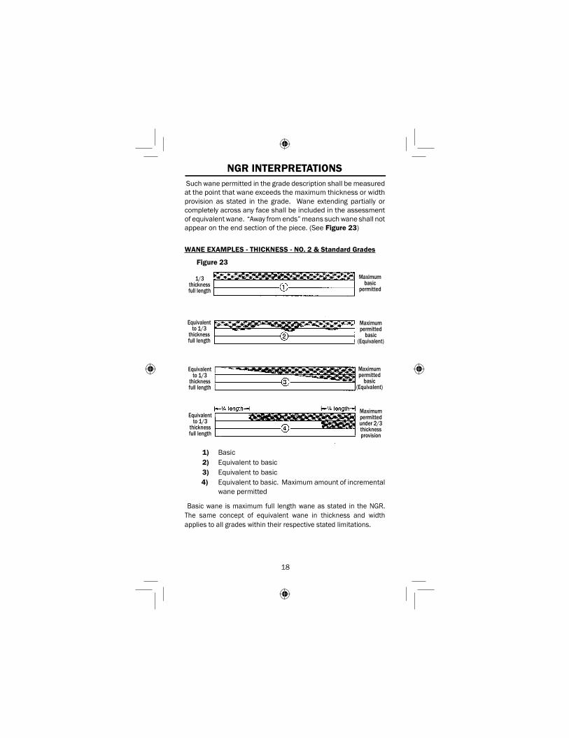
Such wane permitted in the grade description shall be measured at the point that wane exceeds the maximum thickness or width provision as stated in the grade. Wane extending partially or completely across any face shall be included in the assessment of equivalent wane. “Away from ends” means such wane shall not appear on the end section of the piece. (See Figure 23)
WANE EXAMPLES - THICKNESS - NO. 2 & Standard Grades
1) Basic 2) Equivalent to basic 3) Equivalent to basic4) Equivalent to basic. Maximum amount of incremental
wane permitted
Basic wane is maximum full length wane as stated in the NGR. The same concept of equivalent wane in thickness and width applies to all grades within their respective stated limitations.
NGR INTERPRETATIONS
Figure 23
Maximum permitted
basic (Equivalent)
Maximum permitted under 2/3 thickness provision
1/3 thickness full length
Equivalent to 1/3
thicknessfull length
Equivalent to 1/3
thicknessfull length
Equivalent to 1/3
thicknessfull length
Maximum basic
permitted
Maximum permitted
basic (Equivalent)

19
NGR INTERPRETATIONS
1
1.17 WARP
1.17.1 Measurement of Crook, Twist and Bow when in CombinationWhen two or more forms of warp are both present in the same piece, only proportionate amounts of each are permitted. Maximum warp is based on gradual deviation from one end of the piece to the other.
1.17.2 Bow is limited according to thickness, not width.
1.17.3 Other Forms of Warp are limited according to width.