energydesign design brief - Energy Design Resources : …€¦ · INTEGRATED DESIGN OF SMALL...
28
contents Introduction 2 Building Design 4 Unit Sizing 6 Unit Selection 8 Distribution Systems 10 Ventilation 13 Thermostats and Controls 16 Commissioning 17 Operations and Maintenance 20 Conclusion 22 For More Information 23 Notes 25 Summary Small HVAC systems are the workhorses of the light commercial building market, which represents more than half of the annual commercial new construction floor area in California. Design, installation, and operations issues can prevent these systems from performing up to their full potential. This design brief focuses on actions that the architects, engineers, and design/build contractors can take to improve the energy efficiency of small HVAC systems, reduce operating costs, and improve indoor comfort and environmental quality. These actions include: ■ Practice energy-efficient design strategies such as reduced lighting power, high-performance glass and skylights, cool roofs, and improved roof insulation techniques in the overall building design. ■ Size units appropriately using American Society of Heating, Refrigerating and Air-Conditioning Engineers, Inc. (ASHRAE) approved methods that account for the energy efficiency strategies implemented in the design, and use reasonable assumptions on plug load power and ventilation air quantities when sizing equipment. ■ Select unit size and airflow based on calculated sensible loads without oversizing. Consider increasing unit flow rate to improve sensible capacity in dry climates. ■ Specify units that meet the Consortium for Energy Efficiency Tier 2 efficiency standards; and incorporate premium efficiency fan motors, thermostatic expansion valves, and factory-installed and run-tested economizers. ■ Design distribution systems with lower velocities to reduce pressure drop and noise. Seal and insulate duct systems located outside the building thermal envelope. energy design resources INTEGRATED DESIGN FOR SMALL COMMERCIAL HVAC By using recommended design methods for rooftop heating, ventilation, and air conditioning (HVAC) systems, significant improvements in operational savings, energy efficiency, and indoor comfort can be achieved. design brief
Transcript of energydesign design brief - Energy Design Resources : …€¦ · INTEGRATED DESIGN OF SMALL...
contents
Introduction 2
Building Design 4
Unit Sizing 6
Unit Selection 8
Distribution Systems 10
Ventilation 13
Thermostats and Controls 16
Commissioning 17
Operations and Maintenance 20
Conclusion 22
For More Information 23
Notes 25
Summary
Small HVAC systems are the workhorses of the light commercial
building market, which represents more than half of the annual
commercial new construction floor area in California. Design,
installation, and operations issues can prevent these systems
from performing up to their full potential. This design brief
focuses on actions that the architects, engineers, and design/build
contractors can take to improve the energy efficiency of small
HVAC systems, reduce operating costs, and improve indoor
comfort and environmental quality. These actions include:
� Practice energy-efficient design strategies such as reduced
lighting power, high-performance glass and skylights, cool
roofs, and improved roof insulation techniques in the
overall building design.
� Size units appropriately using American Society of Heating,
Refrigerating and Air-Conditioning Engineers, Inc. (ASHRAE)
approved methods that account for the energy efficiency
strategies implemented in the design, and use reasonable
assumptions on plug load power and ventilation air
quantities when sizing equipment.
� Select unit size and airflow based on calculated sensible
loads without oversizing. Consider increasing unit flow rate
to improve sensible capacity in dry climates.
� Specify units that meet the Consortium for Energy Efficiency
Tier 2 efficiency standards; and incorporate premium
efficiency fan motors, thermostatic expansion valves, and
factory-installed and run-tested economizers.
� Design distribution systems with lower velocities to reduce
pressure drop and noise. Seal and insulate duct systems
located outside the building thermal envelope.
energydesignresources
INTEGRATED DESIGN FOR SMALL COMMERCIAL HVAC
By using recommended design
methods for rooftop heating,
ventilation, and air conditioning
(HVAC) systems, significant
improvements in operational
savings, energy efficiency, and
indoor comfort can be achieved.
design brief
� Operate ventilation systems continuously to provide
adequate ventilation air. Incorporate demand-controlled
ventilation to reduce heating and cooling loads.
� Specify commercial grade thermostats with the capability to
schedule fan operation and heating and cooling setpoints
independently.
� Commission the systems prior to occupancy through a
combination of checklists and functional testing of
equipment control, economizer operation, airflow rate, and
fan power.
� Develop clear expectations of the services provided by
HVAC maintenance personnel.
Introduction
This design brief incorporates findings from a recent study of
small HVAC systems in commercial buildings conducted for the
California Energy Commission (CEC).1 A total of 75 buildings
and 215 roof top units were studied. The project identified a
number of issues with HVAC systems that are installed and
operated in the field. The problems included broken
economizers, improper refrigerant charge, fans running during
unoccupied periods, fans that cycle on and off with a call for
heating and cooling rather than providing continuous ventilation
air, low airflow, inadequate ventilation air, and simultaneous
heating and cooling. Correcting these problems represents a
major opportunity for improvements in energy efficiency,
operations, and indoor comfort.
Why Small HVAC?
Packaged direct expansion (DX) air conditioners and heat
pumps cool more than half of the total commercial new
construction floor space in California.2 Of these, single package
rooftop air conditioners dominate the market, representing
approximately three-quarters of the total DX system capacity.
PAGE 2 INTEGRATED DESIGN OF SMALL COMMERCIAL HVAC

PAGE 3INTEGRATED DESIGN OF SMALL COMMERCIAL HVAC
The rooftop air conditioner market is dominated by small
systems, defined here as systems 10 tons and smaller,
representing almost 60 percent of the total installed DX cooling
capacity. The most popular unit size (in terms of units sold) is
five tons (Figures 1 and 2).
These small rooftop units are the workhorses of the
commercial building industry, yet many systems fail to reach
their full potential due to problems with design, installation,
and operation.
Figure 1: Floor space distribution of HVAC systems in newcommercial buildings in California
Single package DX air conditioners are the most popular HVAC system typein new construction in the state, cooling about 44 percent of the totalfloorspace. Built-up systems are the second most popular, conditioningabout 17 percent of the total floorspace.The combined total of singlepackage and split DX air conditioners and heat pumps represents slightlymore than half of the total floorspace in California. Note that a significantportion (about 19 percent) of the total floorspace is not cooled.
Source: Architectural Energy Corporation

PAGE 4 INTEGRATED DESIGN OF SMALL COMMERCIAL HVAC
Building Design
HVAC systems, like all systems in the building, do not function
in isolation, but are part of an interactive system of components.
Before addressing the design of the HVAC system, it is important
to address several aspects of building design that influence the
loads imposed on the HVAC system. By including these energy
efficiency strategies in the building design, the size and energy
consumption of the HVAC system can be reduced.
Reduce Lighting Power
Lighting represents a major opportunity for energy savings in
small buildings. Although Title 24 is one of the most stringent
energy codes in the country, there is ample opportunity to
reduce lighting power below Title 24 allowances. New
generation T-5 and T-8 lamps, fluorescent high-bay fixtures,
task/ambient lighting design, lighting controls, and daylighting
represent opportunities to reduce lighting energy and the size of
the HVAC system required to remove heat generated by lighting
Figure 2: Distribution of packaged DX system size
In terms of number of systems installed, the most popular packaged DX system size is five tons. Units between one and 10 tonsrepresent close to 90 percent of the total unit sales in new buildings in California.
HVAC Unit Size Distribution by Quantity
0%
5%
10%
15%
20%
25%
30%
1 2 3 4 5 6 7 10 12 15 20 25 30 40 50 75 100
Unit size (ton)
Estim
ated
NRN
C Un
itary
Sys
tem
Mar
ket Sh
are
Source: Architectural Energy Corporation
PAGE 5INTEGRATED DESIGN OF SMALL COMMERCIAL HVAC
systems. Lighting amounts to approximately 30 percent of the
energy consumed in typical office buildings. The lighting
designer should try to design to lighting power density levels
that are 10 percent less than Title 24 allowances.
Use High-Performance Glazing and Skylights
High-performance glass also represents a major opportunity for
energy efficiency in commercial buildings. Tinted, low-e glazing
systems that reduce solar heat gain and conduction losses are
available from most glass suppliers, thereby reducing the size of
the air conditioning system. High-performance glass also
improves occupant thermal comfort and reduces glare.
Similarly, high-performance skylights are available that reduce
solar heat gains and heat conductance, while maintaining
sufficient visible light transmission for daylighting applications.
Title 24 requirements exclude single pane glass from most
applications, and require double pane, low-e glass in many
climate zones. However, glazing systems with higher
performance are available in virtually all applications.
Use Cool Roofing Materials
Roofing materials with low solar absorptance and high thermal
emittance (“cool” roofs) can reduce peak HVAC loads and
energy consumption. Cool roofs reflect solar radiation while
enhancing radiant heat transfer to the sky, thus reducing the
“roof” load of the building. Reductions in heat gains through the
roof have an effect on the temperature of the plenum space
located between the drop ceiling and the roof, which contains
the majority of the ductwork in small commercial buildings.
Duct heat gains and air leakage losses (especially on the return
side) can increase HVAC loads on the order of 30 percent, so a
cool plenum can reduce energy consumption and improve
occupant comfort, especially in commercial buildings where
systems run continuously during occupied hours. Cool roofs can
also reduce the outdoor air temperature at the roof level.
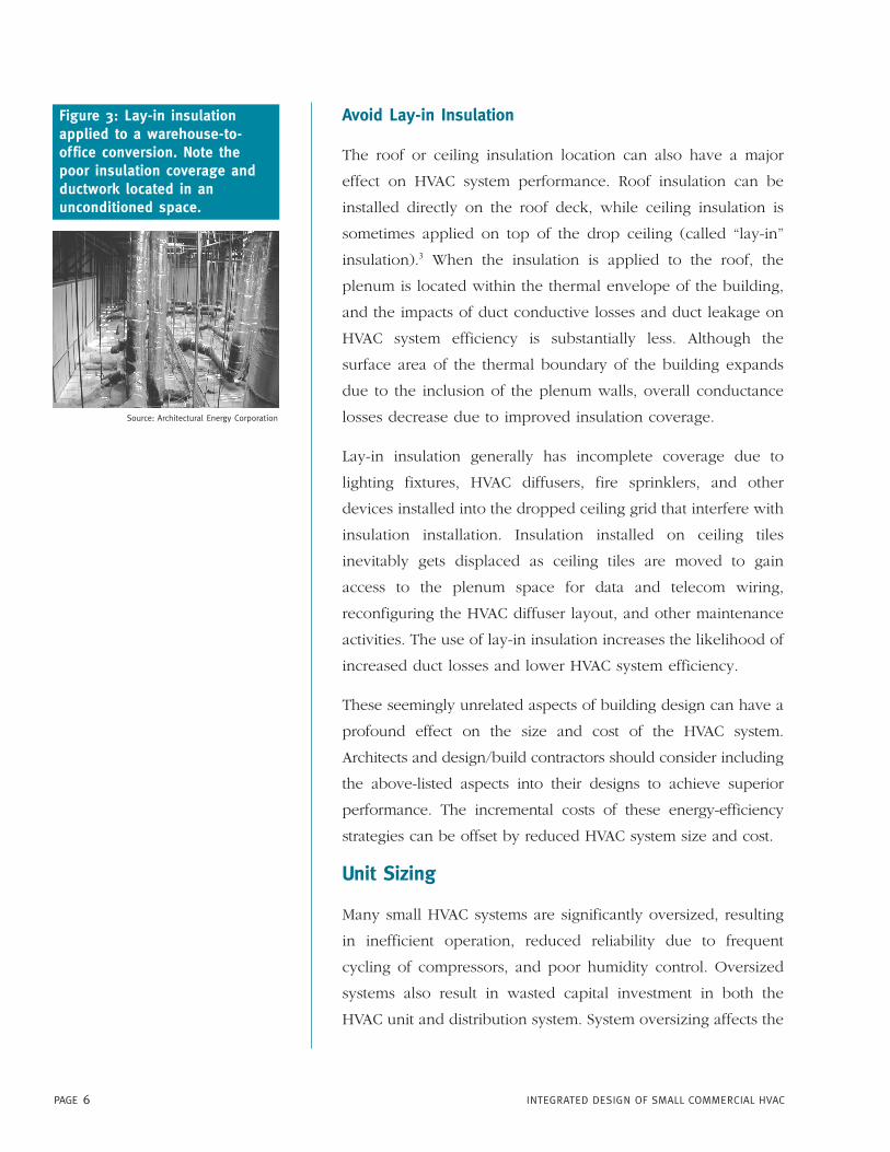
Avoid Lay-in Insulation
The roof or ceiling insulation location can also have a major
effect on HVAC system performance. Roof insulation can be
installed directly on the roof deck, while ceiling insulation is
sometimes applied on top of the drop ceiling (called “lay-in”
insulation).3 When the insulation is applied to the roof, the
plenum is located within the thermal envelope of the building,
and the impacts of duct conductive losses and duct leakage on
HVAC system efficiency is substantially less. Although the
surface area of the thermal boundary of the building expands
due to the inclusion of the plenum walls, overall conductance
losses decrease due to improved insulation coverage.
Lay-in insulation generally has incomplete coverage due to
lighting fixtures, HVAC diffusers, fire sprinklers, and other
devices installed into the dropped ceiling grid that interfere with
insulation installation. Insulation installed on ceiling tiles
inevitably gets displaced as ceiling tiles are moved to gain
access to the plenum space for data and telecom wiring,
reconfiguring the HVAC diffuser layout, and other maintenance
activities. The use of lay-in insulation increases the likelihood of
increased duct losses and lower HVAC system efficiency.
These seemingly unrelated aspects of building design can have a
profound effect on the size and cost of the HVAC system.
Architects and design/build contractors should consider including
the above-listed aspects into their designs to achieve superior
performance. The incremental costs of these energy-efficiency
strategies can be offset by reduced HVAC system size and cost.
Unit Sizing
Many small HVAC systems are significantly oversized, resulting
in inefficient operation, reduced reliability due to frequent
cycling of compressors, and poor humidity control. Oversized
systems also result in wasted capital investment in both the
HVAC unit and distribution system. System oversizing affects the
PAGE 6 INTEGRATED DESIGN OF SMALL COMMERCIAL HVAC
Source: Architectural Energy Corporation
Figure 3: Lay-in insulationapplied to a warehouse-to-office conversion. Note thepoor insulation coverage andductwork located in anunconditioned space.
ability of the system to provide simultaneous economizer and
compressor operation, and exacerbates problems with
distribution system fan power, since larger units are supplied
with larger fans.
Use Sizing Methods Responsive to Efficiency Strategies
A variety of sizing methodologies are used to determine HVAC
system size, including “rule of thumb” sizing based on square
foot per ton (sf/ton), manual methods (e.g. ACCA Manual N),
and computerized load calculations. A recent survey of design
practices in the small commercial building market indicated
that although computerized load calculations are used more
often than manual methods, the assumptions used in the load
calculations are based on conservative assumptions about the
building shell, lighting design, and occupant densities.4 To
reap the advantages of lower first costs, energy efficiency
strategies that reduce peak loads should be included in the
load calculations.
Use Reasonable Assumptions for Plug Loadsand Ventilation Air
Engineers often base HVAC sizing decisions on the full
nameplate or “connected” load of computers, copiers, printers,
and so on; and assume simultaneous operation of such
equipment. In fact, most of this equipment operates at a fraction
of the nameplate value, and rarely operates simultaneously.5
Many HVAC designs are based on plug load assumptions on the
order of five W/sf in office spaces. According to an ASHRAE
study (see sidebar), one W/sf is a reasonable upper bound
when equipment diversity and reasonable estimates of the true
running load are included.
The peak occupant load and the corresponding ventilation
load can contribute substantially to equipment capacity in
certain spaces such as lobbies and public assembly areas.
Often actual occupant loads are substantially less than peak
PAGE 7INTEGRATED DESIGN OF SMALL COMMERCIAL HVAC
ASHRAE Study on Plug Loads in Offices
An ASHRAE study on plug loads
measured equipment load densities in
44 commercial office buildings. The
measured equipment power ranged
between 0.4 and 1.2 W/sf. Values above
1.0 W/sf occurred in only five percent of
the square footage studied.
Source: ASHRAE Journal, December 1997.

egress loads to which building codes often defer. While code
changes may be in order, it also makes sense for designers to
be knowledgeable about the applicable code and balance
good air quality with energy efficiency. Many building codes
reference ASHRAE Standard 62, which allows the designer to
base the design on the actual anticipated occupant density, so
long as justification is provided.
Avoid Oversizing
California Title 24 limits cooling capacity to 121 percent of the
calculated peak cooling load. Since most sizing methods are
based on conservative assumptions, it is recommended that
designers use the calculated load and round up to the next
available unit size only to avoid excessive oversizing.
Unit Selection
Efficiency
Energy codes are generally set to correspond to the basic
“standard efficiency” HVAC unit. High efficiency units are
available in most size ranges that are up to 30 percent more
efficient than code. These units generally incorporate larger
condenser and evaporator coils, efficient compressors,
improved cabinet insulation, and higher efficiency fans and
motors. Designers should consider specifying units that meet
the Consortium for Energy Efficiency (CEE) Tier 2 efficiency
standards. It is also important to consider both the rated full
load energy efficiency ratio (EER), and the seasonal energy
efficiency ratio (SEER) when selecting a unit. However, if the
unit design is optimized for efficient part-load rather than peak
load operation, multi-compressor units with high SEERs may
not perform much better than a standard unit at peak cooling
conditions, since the SEER includes part-load efficiency in the
overall calculation.
PAGE 8 INTEGRATED DESIGN OF SMALL COMMERCIAL HVAC
Table 1. Title 20 (2003), Title 24(2001) and CEE Tier 2 EfficiencyStandards
Source: CEC and CEE
Size Title 20/24 Tier 2<5.4 ton 9.7 SEER 13 SEER/
11.2 EER5.4–11.2 ton. 10.3 EER 11 EER
PAGE 9INTEGRATED DESIGN OF SMALL COMMERCIAL HVAC
Select Capacity Based on Design Conditions
Designers should consider the unit capacity under actual design
conditions, not nominal values. The peak cooling capacity is
reduced as outdoor temperatures increase. This can be
especially important in desert climates where peak cooling
conditions on the roof can exceed the data in manufacturers’
standard catalogs. The unit should be sized to meet the
calculated sensible load, and the latent cooling capacity should
be reviewed. High-efficiency equipment generally has less latent
cooling capacity than standard equipment. Also, energy-efficient
buildings have reduced sensible loads but comparable outdoor
air requirements compared to standard buildings; thus the
sensible heat ratio of an energy-efficient building may be
reduced.
Select Airflow Rate to Meet Sensible Loads
The cooling capacity of most packaged air conditioners is based
on a nominal flow rate of 400 cfm (cubic feet/minute) per ton
of cooling capacity. Nominal flow rates in packaged equipment
are selected to provide adequate dehumidification in climates
that are more humid than California. Increasing the flow rate
can extract extra sensible cooling capacity out of the unit,
allowing the selection of a smaller “nominal” unit. However,
the designer should assess the fan energy, which may increase
dramatically with higher flow rates, if the unit capacity is near
the maximum offered in a particular case size.
Specify Premium Efficiency Fan Motors
Premium efficiency fan motors are important in commercial
applications, since fans in general run continuously during
occupied periods. In systems equipped with economizers in
mild climates such as coastal California, fan energy can be a
significant portion of the total HVAC energy consumption.
Selection of a premium efficiency motor on the supply fan is
cost effective in all climates.
� When selecting a unit,
designers should consider
peak rooftop temperature
and sensible heat ratio
under design conditions.
� Designers should also
evaluate the trade-off
between additional sensible
cooling capacity and fan
power when selecting air
flow rate.

PAGE 10 INTEGRATED DESIGN OF SMALL COMMERCIAL HVAC
Specify Thermostatic Expansion Valves
Refrigerant charge in units degrades over time, due to
refrigerant leaks and/or poor maintenance practices.
Specifying units with thermostatic expansion valves makes the
units more tolerant of refrigerant charge variations by
maintaining unit efficiency over a wide range of under- or
over-charged conditions. Thermostatic expansion valves are
available as a factory option in most units.
Specify Reliable Economizers
Economizers are required by code in units exceeding 6.25 tons
and are used in many smaller units. Energy savings from
functioning economizers can exceed 50 percent in certain
climates and building types. Although most manufacturers
offer a factory-installed economizer, the majority of
economizers are installed by the distributor or in the field.
Specifying a factory installed and fully run-tested economizer
can improve reliability.
Distribution Systems
After sizing and selection, the distribution system (ductwork
and diffusers) is the next important part of the HVAC
system. Installed costs for duct systems can approach the
cost of the HVAC unit itself. Often, there is intense pressure
to reduce duct system costs. However, the quality of the
duct system can have a profound effect on the efficiency
and comfort delivered by the HVAC system. Fan energy in
small commercial buildings can approach the cooling energy
consumption. Duct losses through leakage and conduction
can affect the efficiency of the system and the amount of
cooling delivered to the space. A poorly balanced distribution
system is one of the leading causes of poor indoor comfort in
small systems.
Figure 4: Thermostatic expansionvalves (above) and direct driveeconomizer actuators (below)can improve unit reliability.
Source: Sporlan Valve Companywww.sporlan.com
Source: Belimo Aircontrolswww.belimo.com

PAGE 11INTEGRATED DESIGN OF SMALL COMMERCIAL HVAC
Reduce Duct System Pressure Drop
Poor ductwork design can lead to inadequate HVAC unit airflow
and excessive fan power. Tested airflow rates in buildings
averaged about 325 cfm/ton, rather than the nominal 400 cfm/ton
used in system efficiency ratings. Reduced airflow can
contribute to coil icing, comfort problems, and a reduction in
cooling efficiency of approximately 10 percent.
Design values. Duct systems in small buildings are generally
sized using the equal friction or modified equal friction
method. Principle design variables are the design velocity
(chosen for noise control) or the design friction loss (in Water
Columns per 100 ft.). Typical design friction rates are 0.1 inch
WC per 100 ft. in commercial buildings. Reducing the design
friction rate to 0.05 inch WC per 100 ft. increases the duct size
and costs by 15 percent, but cuts the portion of the total
pressure drop attributable to the ductwork by 50 percent,
and the overall distribution system pressure drop by
approximately 40 percent when diffuser losses are included.
Upsizing the duct system can provide fan energy savings on
the order of 15 to 20 percent.
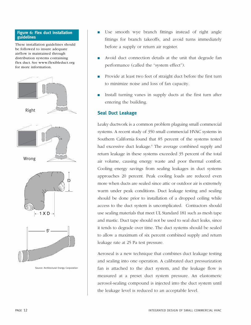
Use of flex duct. Flex duct, which is used extensively in light
commercial construction, has more than a 60 percent higher
pressure drop than galvanized metal duct of the same
diameter. Flex duct runs should be limited to six feet or less.
Flex duct should also be fully extended and well supported
at five-foot intervals to minimize pressure losses. The bend
radius should be greater than one times the duct diameter to
avoid kinking.
Duct layout and fittings. The duct system should be laid out to
minimize duct length, turns, and fittings. Radius or section
elbows are suggested for all turns greater than 45 degrees. Other
recommendations include:
Source: ASHRAE Handbook of Fundamentals (2001)
Figure 5: Flex duct should befully extended to minimizepressure drop. A 30 percentreduction in flex duct extensioncauses a four-fold increase inpressure drop.
PAGE 12 INTEGRATED DESIGN OF SMALL COMMERCIAL HVAC
� Use smooth wye branch fittings instead of right angle
fittings for branch takeoffs, and avoid turns immediately
before a supply or return air register.
� Avoid duct connection details at the unit that degrade fan
performance (called the “system effect”).
� Provide at least two feet of straight duct before the first turn
to minimize noise and loss of fan capacity.
� Install turning vanes in supply ducts at the first turn after
entering the building.
Seal Duct Leakage
Leaky ductwork is a common problem plaguing small commercial
systems. A recent study of 350 small commercial HVAC systems in
Southern California found that 85 percent of the systems tested
had excessive duct leakage.6 The average combined supply and
return leakage in these systems exceeded 35 percent of the total
air volume, causing energy waste and poor thermal comfort.
Cooling energy savings from sealing leakages in duct systems
approaches 20 percent. Peak cooling loads are reduced even
more when ducts are sealed since attic or outdoor air is extremely
warm under peak conditions. Duct leakage testing and sealing
should be done prior to installation of a dropped ceiling while
access to the duct system is uncomplicated. Contractors should
use sealing materials that meet UL Standard 181 such as mesh tape
and mastic. Duct tape should not be used to seal duct leaks, since
it tends to degrade over time. The duct systems should be sealed
to allow a maximum of six percent combined supply and return
leakage rate at 25 Pa test pressure.
Aeroseal is a new technique that combines duct leakage testing
and sealing into one operation. A calibrated duct pressurization
fan is attached to the duct system, and the leakage flow is
measured at a preset duct system pressure. An elastomeric
aerosol-sealing compound is injected into the duct system until
the leakage level is reduced to an acceptable level.
Figure 6: Flex duct installationguidelines
These installation guidelines shouldbe followed to insure adequateairflow is maintained throughdistribution systems containingflex duct. See www.flexibleduct.orgfor more information.
Source: Architectural Energy Corporation
Right
Wrong
PAGE 13INTEGRATED DESIGN OF SMALL COMMERCIAL HVAC
Increase Duct Insulation Levels to R-8
Most duct systems are insulated with one inch of fiberglass
insulation (R-4.2). Duct wrap and duct liner two inches thick are
commonly available, and improve the insulation level to R-8.
Increased insulation is cost effective in duct systems located
outside the conditioned space, such as attics or plenum spaces
with lay-in insulation, or outdoors.
Reduce Duct System Noise
Poorly designed duct systems produce and/or convey
noise. Excessive noise can degrade indoor environmental
quality (IEQ) and productivity in certain spaces, especially
classrooms. Research conducted by the Heshong-Mahone
Group for the CEC (see listing under “For More
Information” section) listed noise as a leading problem in
school HVAC systems.
Reducing the design friction rates also reduces duct
velocity, which reduces duct noise. The use of lined ducts
should be avoided for noise control, since the duct lining
increases pressure drop. A common problem is to solve a
noise problem related to high duct velocity with duct
liners or silencers, which further increases pressure drop.
Increasing duct size and following good design practices at
diffuser connections can address noise and pressure drop
problems simultaneously.
Ventilation
Providing adequate ventilation is a key component of indoor
air quality. Strategies to provide adequate ventilation are often
at odds with energy efficiency; however, meeting ventilation
code requirements should be the first priority of designers
and operators of buildings, with the goal of meeting these
requirements in the most energy efficient manner possible.
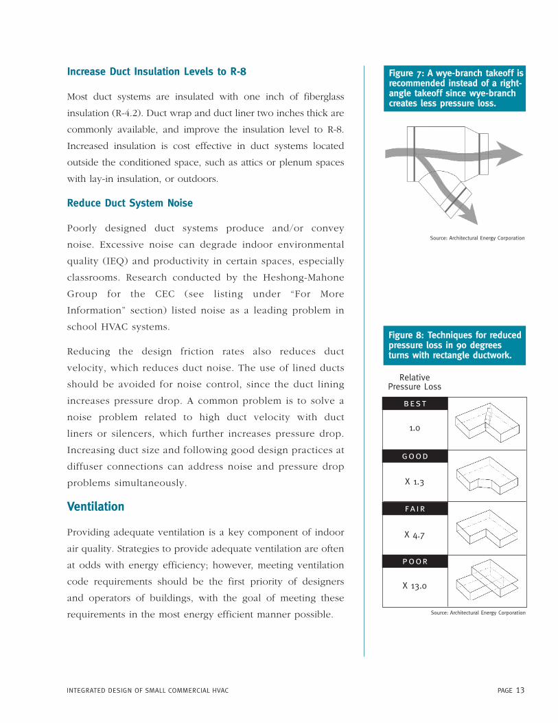
Figure 7: A wye-branch takeoff isrecommended instead of a right-angle takeoff since wye-branchcreates less pressure loss.
Figure 8: Techniques for reducedpressure loss in 90 degreesturns with rectangle ductwork.
Source: Architectural Energy Corporation
Source: Architectural Energy Corporation
RelativePressure Loss
1.0
X 1.3
X 4.7
X 13.0
best
good
fair
poor

Operate Unit Fans Continuously
Building codes generally require continuous ventilation during
occupied hours. This is generally accomplished by operating the
HVAC unit fan continuously and introducing fresh air at the unit.
When HVAC unit fans are cycled on and off with a call for
heating or cooling, the ventilation rates drop dramatically. The
effect of cycling fans on effective ventilation rates is shown in
Figure 9. It should be noted that the effective ventilation rate for
units with cycling fans is on the order of five cfm/person, or
about one third the minimum rate mandated by the Title 24
Standards. Continuous fan operation also reduces stuffiness and
localized temperature variations that are among the most
common complaints in buildings served by small rooftop units.
PAGE 14 INTEGRATED DESIGN OF SMALL COMMERCIAL HVAC
Figure 9: Effective ventilation rate for HVAC units with continuous and cycling fans
Average Effective Ventilation Rate Under Code Compliant and Worst Case Fan Control Strategies
0.0
5.0
10.0
15.0
20.0
25.0
30.0
35.0
1 2 3 4 5 6 7 8 9 10 11 12 13 14 15 16
Climate Zone
cfm
/per
son
Code Compliant Worst Case
In both cases, the minimum outdoor air damper is set to provide 15 cfm/person of outside air. The code compliant case usedcontinuous ventilation and an air-side economizer. Economizer operation increased the effective ventilation rate above thenominal 15 cfm/person rate. A unit not equipped with an economizer and operated with cycling fans provided an effectiveventilation rate of less than five cfm/person in most climate zones.
Source: Architectural Energy Corporation
PAGE 15INTEGRATED DESIGN OF SMALL COMMERCIAL HVAC
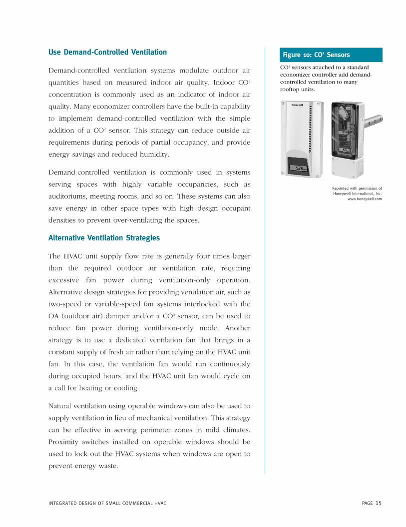
CO2 sensors attached to a standardeconomizer controller add demand-controlled ventilation to manyrooftop units.
Figure 10: CO2 SensorsUse Demand-Controlled Ventilation
Demand-controlled ventilation systems modulate outdoor air
quantities based on measured indoor air quality. Indoor CO2
concentration is commonly used as an indicator of indoor air
quality. Many economizer controllers have the built-in capability
to implement demand-controlled ventilation with the simple
addition of a CO2 sensor. This strategy can reduce outside air
requirements during periods of partial occupancy, and provide
energy savings and reduced humidity.
Demand-controlled ventilation is commonly used in systems
serving spaces with highly variable occupancies, such as
auditoriums, meeting rooms, and so on. These systems can also
save energy in other space types with high design occupant
densities to prevent over-ventilating the spaces.
Alternative Ventilation Strategies
The HVAC unit supply flow rate is generally four times larger
than the required outdoor air ventilation rate, requiring
excessive fan power during ventilation-only operation.
Alternative design strategies for providing ventilation air, such as
two-speed or variable-speed fan systems interlocked with the
OA (outdoor air) damper and/or a CO2 sensor, can be used to
reduce fan power during ventilation-only mode. Another
strategy is to use a dedicated ventilation fan that brings in a
constant supply of fresh air rather than relying on the HVAC unit
fan. In this case, the ventilation fan would run continuously
during occupied hours, and the HVAC unit fan would cycle on
a call for heating or cooling.
Natural ventilation using operable windows can also be used to
supply ventilation in lieu of mechanical ventilation. This strategy
can be effective in serving perimeter zones in mild climates.
Proximity switches installed on operable windows should be
used to lock out the HVAC systems when windows are open to
prevent energy waste.
Reprinted with permission of Honeywell International, Inc.
www.honeywell.com
PAGE 16 INTEGRATED DESIGN OF SMALL COMMERCIAL HVAC
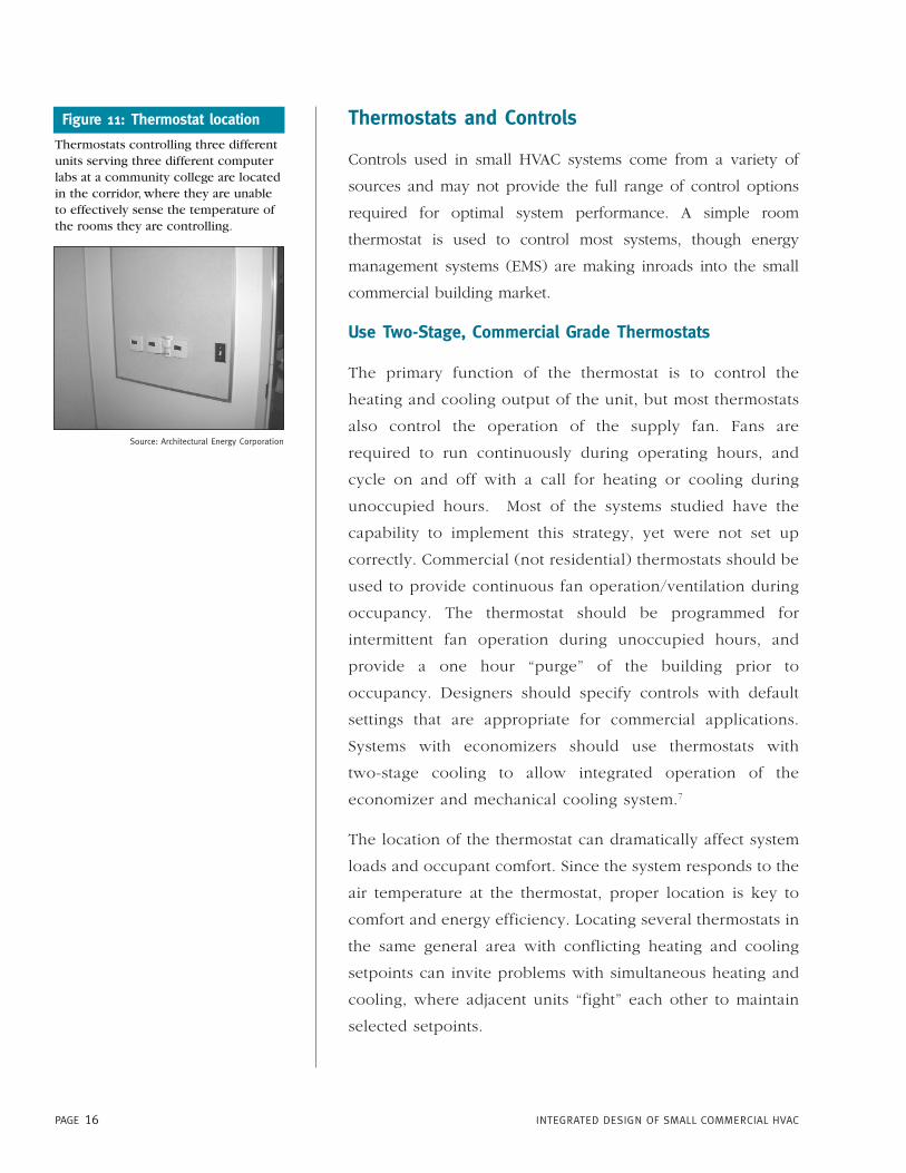
Figure 11: Thermostat location
Thermostats controlling three differentunits serving three different computerlabs at a community college are locatedin the corridor, where they are unableto effectively sense the temperature ofthe rooms they are controlling.
Source: Architectural Energy Corporation
Thermostats and Controls
Controls used in small HVAC systems come from a variety of
sources and may not provide the full range of control options
required for optimal system performance. A simple room
thermostat is used to control most systems, though energy
management systems (EMS) are making inroads into the small
commercial building market.
Use Two-Stage, Commercial Grade Thermostats
The primary function of the thermostat is to control the
heating and cooling output of the unit, but most thermostats
also control the operation of the supply fan. Fans are
required to run continuously during operating hours, and
cycle on and off with a call for heating or cooling during
unoccupied hours. Most of the systems studied have the
capability to implement this strategy, yet were not set up
correctly. Commercial (not residential) thermostats should be
used to provide continuous fan operation/ventilation during
occupancy. The thermostat should be programmed for
intermittent fan operation during unoccupied hours, and
provide a one hour “purge” of the building prior to
occupancy. Designers should specify controls with default
settings that are appropriate for commercial applications.
Systems with economizers should use thermostats with
two-stage cooling to allow integrated operation of the
economizer and mechanical cooling system.7
The location of the thermostat can dramatically affect system
loads and occupant comfort. Since the system responds to the
air temperature at the thermostat, proper location is key to
comfort and energy efficiency. Locating several thermostats in
the same general area with conflicting heating and cooling
setpoints can invite problems with simultaneous heating and
cooling, where adjacent units “fight” each other to maintain
selected setpoints.

PAGE 17INTEGRATED DESIGN OF SMALL COMMERCIAL HVAC
Controller Options and Interfaces
Modern HVAC units can be configured with a variety of controller
options, including standard electromechanical controls,
microprocessor controls, and controllers with EMS interface
capability. Standard controls allow the use of thermostats from a
variety of vendors. In some units with microprocessor control, the
thermostat control logic is contained within the unit controller
and the zone thermostat is merely a temperature sensor.
Interfaces to energy management systems allow the units to be
controlled by one of several energy management systems,
including both manufacturer-supplied systems and third party
systems. These interfaces allow the energy management system to
take over most of the unit control function, including calls for
heating and cooling, fan operation and scheduling, and
economizer control. Additional digital I/O channels are included
to provide alarm capability for fan failure, dirty filters, compressor
high- or low-pressure lockout, and economizer status. Supply and
return air temperature information can also be transmitted to the
EMS console. These systems are very popular in chain retail and
foodservice environments, allowing central control over HVAC
system operation and limited unit diagnostic capability. The
systems work best in buildings that are occupied on a regular
schedule; applications in schools have been problematic.
Commissioning
Commissioning is a quality-assurance process that increases the
likelihood that a new building will meet the intent of the design
team and, ultimately, the client’s expectations. In large projects,
the commissioning process can encompass the entire design and
construction process:
� During the design phase, commissioning begins with the
selection of a commissioning agent—who helps ensure that
the project documentation reflects the intentions of both the
designer and owner.

� Next, the designer incorporates commissioning requirements
into the design specifications.
� During construction, the commissioning agent is responsible
for inspecting the building to identify construction defects
that are difficult to correct after the building is finished.
� When the project is near completion, the commissioning
agent and contractors conduct performance tests of the
systems to be commissioned.
� At the end of the commissioning process, the designer and
vendors train the building operators on how to properly
operate and maintain the building.
Commissioning of small HVAC systems generally focuses on
providing documentation of the design intent, including
commissioning testing in the building plans and
specifications, testing the system, correcting deficiencies,
and providing operation and maintenance training to the
building occupants. Incorporating the commissioning
requirements into the specifications is very important,
since the contractor will base the bid on the plans and
specifications. Also, setting the expectation up front that
commissioning will be done will save a lot of trouble during
the construction process. The commissioning plan should
also include a sample maintenance contract to assist the
building owner or operator in obtaining ongoing
maintenance services.
Perform Pre-Functional Inspections
Prior to conducting any commissioning tests, the units are
inspected according to a checklist called a pre-functional
checklist. Items on the checklist generally include:
� Document submittal (spec sheets, operations and
maintenance instructions).
� Verification of correct make and model number.
PAGE 18 INTEGRATED DESIGN OF SMALL COMMERCIAL HVAC
Figure 12: Flow grid measuresairflow
A flow grid is used to measure as-installed airflow rate. A series of flowgrids (see below) are installed in placeof the filters; the airflow rate througheach flow grid is displayed on a digitalmanometer.
Source: Architectural Energy Corporation
PAGE 19INTEGRATED DESIGN OF SMALL COMMERCIAL HVAC
� Installation checks, such as tight curb connections, operable
cabinet door with gaskets in place, shipping materials and
hold-downs removed, and adequate maintenance access.
� Duct insulation installed and in good condition.
� Filters installed properly.
� Fan motor aligned and belt tension correct.
� Economizer linkages tight, with smooth operation.
� Safety disconnect properly installed.
Perform Functional Performance Tests
The heart of the commissioning process is a series of tests called
functional performance tests. For small packaged units,
functional performance testing usually includes:
� Cycling unit through its various operating modes and
observing unit response according to the control sequence
of operations. For example, does the outdoor air damper
close when the unit is turned off? Does the second
compressor come on during a second stage call for cooling?
� Performing economizer tests—Does the economizer actuator
work? Do the dampers move freely over their full range? Are
the sensors calibrated? Does the unit respond correctly when
subjected to conditions where the economizer should operate?
� Checking sensor calibration—Are the room temperature,
outdoor air temperature, and/or supply air temperature sensors
installed in a reasonable location and properly calibrated?
� Verifying correct rotation of supply and condenser fan
motors.
� Checking for correct thermostat programming, including fan
controls—Are the set points and operating schedule correct
according to the design documents? Does the fan run
continuously during occupied hours?
PAGE 20 INTEGRATED DESIGN OF SMALL COMMERCIAL HVAC
Additional functional tests may also be included. These
tests can detect less obvious, but important problems with
HVAC installations:
� Verify airflow through unit is correct. This generally requires
the use of a flow grid to measure unit airflow.
� Verify duct leakage is within acceptable limits. This generally
requires the use of a duct pressurization device to measure
duct leakage rate.
� Verify correct refrigerant charge. Refrigerant pressure
measurements combined with refrigerant line
temperatures should be checked to verify correct
superheat (for fixed throttling devices) or correct sub
cooling (for thermostatic expansion valve units).
� Verify adequate outdoor airflow. A flow grid can be used
to make this measurement.
Operations and Maintenance
Packaged rooftop units are generally designed for a shorter
service life than other HVAC equipment. The units are also
exposed to various weather elements that can be stressful to the
equipment operation. Both factors can contribute to more
frequent maintenance needs. Problems tend to occur during
periods of system stress caused by extremely hot or cold
weather. This discourages timely inspection and repair. If the
problems occur during wet or icy weather, maintenance and
repair can actually be hazardous.
Keeping these issues in mind will help building owners better
plan maintenance of units. A little preventive maintenance
during nice weather should help optimize operation, energy
use, and comfort while minimizing “surprises” during
inclement weather.
PAGE 21INTEGRATED DESIGN OF SMALL COMMERCIAL HVAC
Provide Reasonable Access to Rooftop
Maintenance of packaged rooftop units is often ignored because
the units are on the roof. Typical access is by a vertical ladder
and roof hatch. Stored items can block access to the ladder,
which does not encourage frequent inspections. Building
owners should be sure the roof access is kept free of
obstructions, and maintenance personnel have access to the key
to the roof hatch padlock.
Routine Maintenance
Regular maintenance is an important component of energy
efficiency, comfort, and the prevention of premature equipment
failure. Simple routine checks can avoid costly contractor calls
to diagnose or fix simple maintenance problems. A few routine
maintenance items include:
� Check fan belts—tension/wear
� Check filters
� Verify economizer damper linkage/movement
� Check refrigerant—check site glass and test refrigerant charge
� Lubricate moving parts (including dampers and linkage)
� Check access panels for tight fit
� Inspect electrical wiring/connections
� Check coils for debris and clean as necessary
Annual maintenance contracts are common. If considering
one, ensure the staff has good experience. Maintenance
staff in buildings with rooftop units are often under skilled
with limited training and experience. Routine maintenance
tasks should be placed on easy-to-use reference sheets and
lists posted in locations that encourage pro-active
maintenance. Maintenance logs and manufacturer service
instructions for all units should be kept in a readily
accessible binder. Maintenance contracts should require a
log that remains on site.
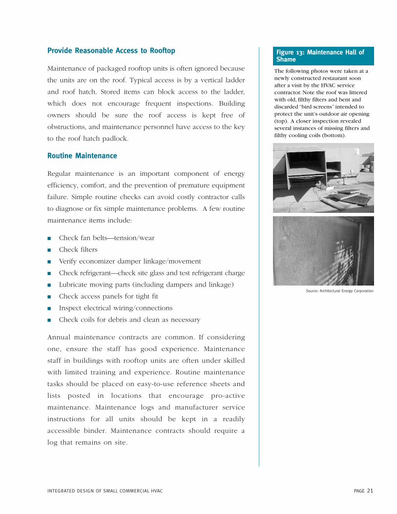
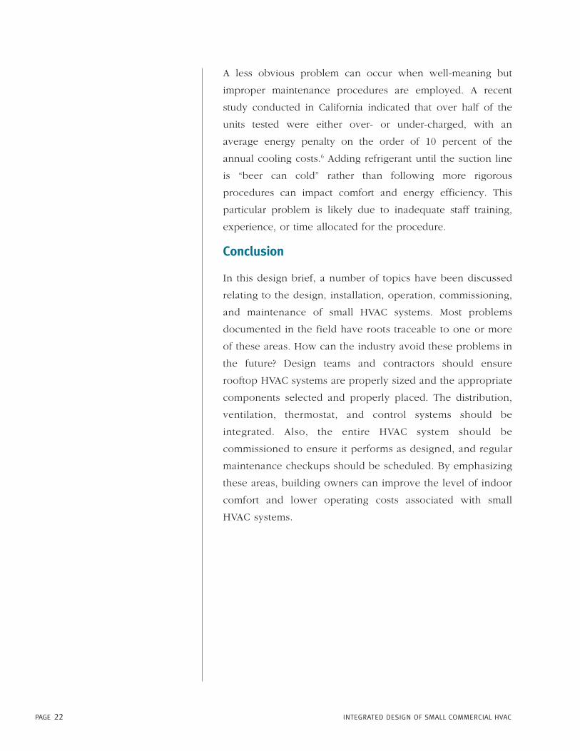
Figure 13: Maintenance Hall ofShame
The following photos were taken at anewly constructed restaurant soonafter a visit by the HVAC servicecontractor. Note the roof was litteredwith old, filthy filters and bent anddiscarded “bird screens” intended toprotect the unit’s outdoor air opening(top). A closer inspection revealedseveral instances of missing filters andfilthy cooling coils (bottom).
Source: Architectural Energy Corporation
PAGE 22 INTEGRATED DESIGN OF SMALL COMMERCIAL HVAC
A less obvious problem can occur when well-meaning but
improper maintenance procedures are employed. A recent
study conducted in California indicated that over half of the
units tested were either over- or under-charged, with an
average energy penalty on the order of 10 percent of the
annual cooling costs.6 Adding refrigerant until the suction line
is “beer can cold” rather than following more rigorous
procedures can impact comfort and energy efficiency. This
particular problem is likely due to inadequate staff training,
experience, or time allocated for the procedure.
Conclusion
In this design brief, a number of topics have been discussed
relating to the design, installation, operation, commissioning,
and maintenance of small HVAC systems. Most problems
documented in the field have roots traceable to one or more
of these areas. How can the industry avoid these problems in
the future? Design teams and contractors should ensure
rooftop HVAC systems are properly sized and the appropriate
components selected and properly placed. The distribution,
ventilation, thermostat, and control systems should be
integrated. Also, the entire HVAC system should be
commissioned to ensure it performs as designed, and regular
maintenance checkups should be scheduled. By emphasizing
these areas, building owners can improve the level of indoor
comfort and lower operating costs associated with small
HVAC systems.
For More Information
New Buildings Institute
The New Buildings Institute hosts a website that contains additional
information about this project and other elements of their PIER research
program. For more information, consult:
www.newbuildings.org/pier
California Energy Commission
The California Energy Commission is responsible for conducting Public Interest
Energy Research on a number of topics. For more information on this and
other PIER Research, consult:
www.energy.ca.gov/pier/buildings
Consortium for Energy Efficiency
The Consortium for Energy Efficiency (CEE) is a non-profit, public benefit
corporation that actively promotes the use of energy-efficient products and
services through its members, including electric and gas utilities, public
benefit administrators (such as state energy offices, non-profit organizations,
and regional energy groups), and research and development laboratories.
They have established efficiency guidelines for commercial rooftop units, and
have published a small commercial HVAC design guideline. For more
information, consult:
www.cee1.org
Air Conditioning and Refrigeration Technology Institute
The Air Conditioning and Refrigeration Technology Institute (ARTI) conducts
the Twenty-First Century Research (21-CR) initiative, which is a private-public
sector research collaboration of the heating, ventilation, air-conditioning and
refrigeration (HVAC/R) industry. ARTI has conducted research into design
practices for small commercial HVAC systems. For more information, consult:
www.arti-21cr.org
Northwest Energy Efficiency Alliance
The Northwest Energy Efficiency Alliance (NEEA), along with Portland Energy
Conservation Inc. (PECI), is conducting a pilot program to assess the market
opportunities for enhanced operation and maintenance services for packaged
heating and cooling systems in small commercial buildings. The pilot project
is developing and testing an array of diagnostic tools and procedures, training
selected contractors, developing marketing materials, and documenting the
market acceptance of the service in selected markets around the Northwest.
For more information, consult:
www.nwalliance.org
PAGE 23INTEGRATED DESIGN OF SMALL COMMERCIAL HVAC
Air Conditioning Contractors Association
The Air Conditioning Contractors Association (ACCA) publishes several
manuals on design practices for small commercial HVAC systems.
For more information, consult:
www.acca.org
Air Diffusion Council
The Air Diffusion Council publishes an installation guideline
for flexible duct systems. For more information, consult:
www.flexibleduct.org
Sheet Metal and Air Conditioning Contractors’ National Association
The Sheet Metal and Air Conditioning Contractors’ National Association
(SMACNA) publishes technical manuals and construction standards
relating to the construction and installation of air distribution systems.
For more information, consult:
www.smacna.org
PAGE 24 INTEGRATED DESIGN OF SMALL COMMERCIAL HVAC

PAGE 25INTEGRATED DESIGN OF SMALL COMMERCIAL HVAC
Notes
1 For more information about this project, see
www.newbuildings.org/pier. Follow the links to
Element 4—Integrated Design of HVAC Systems for
Small Commercial Buildings.
2 See the results of the market research conducted for this
project at www.newbuildings.org/pier.
3 Applications of lay-in insulation were not allowed in earlier
versions of Title 24, and the practice, while not widespread,
is permissible under the current (2001) Standards.
4 See State-of-the-Art Review, Whole Buildings and Building
Envelope Simulation and Design Tools, Air Conditioning
and Refrigeration Technology Institute (ARTI),
www.arti-21cr.org.
5 Modera, M. and Proctor, J. “Combining Duct Sealing and
Refrigerant Charge Testing to Reduce Peak Electricity
Demand in Southern California,” Final Project Report for
Southern California Edison, July 2002.
6 Proctor, et al., Small commercial HVAC system inspections
in Sacramento.
7 Heat pumps may require three dedicated cooling stages.
The additional stage is for the reversing valve.

PAGE 26 INTEGRATED DESIGN OF SMALL COMMERCIAL HVAC

PAGE 27INTEGRATED DESIGN OF SMALL COMMERCIAL HVAC

Energy Design Resources provides information and design tools toarchitects, engineers, lighting designers, and building owners anddevelopers. Our goal is to make it easier for designers to create energy-efficient new nonresidential buildings in California. Energy DesignResources is funded by California utility customers and administered byPacific Gas and Electric Company, San Diego Gas and Electric, SouthernCalifornia Edison, and Southern California Gas Company under theauspices of the California Public Utilities Commission. To learn moreabout Energy Design Resources, please visit our Web site atwww.energydesignresources.com.
This design brief was prepared for Energy Design Resources byArchitectural Energy Corporation, Boulder, Colorado.


![Design Portolio [Small]](https://static.fdocuments.us/doc/165x107/568c4c571a28ab49169fbfdb/design-portolio-small.jpg)