ENERGY up above, down below
36
The French edition of Scientific American POUR LA SCIENCE SPECIAL ISSUE in partnership with MAY 2021 NOT FOR SALE up above, down below ENERGY
Transcript of ENERGY up above, down below

The French edition of Scientific American
POU
R L
A S
CIE
NC
E
SPECIAL ISSUE in partnership with
RÉFÉRENCES COULEUR
24, rue Salomon de Rothschild - 92288 Suresnes - FRANCETél. : +33 (0)1 57 32 87 00 / Fax : +33 (0)1 57 32 87 87Web : www.carrenoir.com
ENGIElogotype_solid_BLUE_CMYK14/04/2015
C100%
Zone de protection 1
Zone de protection 3
Zone de protection 2
MAY 2021 NOT FOR SALE
up above, down belowENERGY

THE TERRA INCOGNITA of energy
CATHERINE MACGREGOR, CHIEF EXECUTIVE OFFICER, ENGIE
If we want to act for the climate, we have no choice but to switch to greener, decarbonized energy but also to reduce the volumes we need by becoming more energy efficient. The challenge is substantial as popu-lation growth means there are more and more people whose basic needs need to be met, while guaranteeing
a high level of comfort. We must adapt continually to accompany this transforma-
tion and fight climate change, not only by rethinking production methods, but also by changing our relationship with energy in order to reduce consumption and greenhouse gas emissions. Innovations and excellence are required to open a new field of possibilities and unlock new potential.
On the way to a low, or even zero-carbon society, the path to follow over the next decade is already more or less laid out, even if everything is not yet set in stone. This road map will see us do away with high carbon sources of energy, develop solar and wind power and make them more competitive, favour local
energy production by encouraging the use of wood, biogas and district heating and cooling networks, move towards carbon-neutral construction and the sus-tainable renovation of existing buildings, develop the market for electric cars and lay the foundations for the decarbonization of the transport sector thanks to renewable gases, in particular hydrogen. We have already explored these exciting subjects in recent years.
In this special issue of Pour la Science, we wanted to go one step further and invite you to explore a terra incognita with us, in other words the most forward-looking, long term technological solutions. Some will search for high altitude sources of energy, whereas others will explore the seas and the depths of the Earth. Geothermal energy will provide heating, cooling and even electricity; large volumes of renewable gases and even heat will be stored in porous rock and salt caverns; and the potential of natural hydrogen will be explored. And what about harnessing tidal or osmotic power to produce green electricity? Airborne wind turbines will access the energy of high-altitude winds and new, low-carbon fuels will help decarbonize aviation. And last but not least, we’ll take you on a long journey through space. By the time you have discovered these many innovations in the company of Pour la Science and ENGIE, you’ll already be one step ahead! nn
DITO
2 ] ENGIE © POUR LA SCIENCE - May 2021
© E
NG
IE /
BRET
ON
VIN
CEN
T

How can we achieve carbon neutrality? By opening up the doors to new frontiers of the Earth!
Let’s go underground: from geothermal energy, to the exploitation of natural hydrogen, to a responsible supply of minerals for renewable energies and the development of hydrogen storage and transport...
Let’s dive under the sea, for producing electricity from wave and tidal, the osmotic energy, and storaging energy at the bottom of the sea.
Let’s get high with airborne wind systems, synthetic fuels and liquefied hydrogen for aviation, and then the production of clean air and food on board spacecraft.
This issue looks at the challenges and prospects of these techno-logies, some of which are already mature, others highly innovative and even emerging, and their impacts, in line with ENGIE’s ambitions of carbon neutrality, sobriety and sustainability.
Energy from new frontiers
ENGIE [ 3 © POUR LA SCIENCE - May 2021
www.pourlascience.fr170 bis boulevard du Montparnasse 75014 ParisTél. 01 55 42 84 00
Group POUR LA SCIENCEEditorial staff director: Cécile LestienneEditor in chief: Maurice MashaalA special issue in partnership with ENGIE: Loïc Mangin and Simon ThurstonArtistic direction and realisation: Ghislaine Salmon-LegagneurCopy editor: Maud BruguièreMarketing & diffusion : Charline Buché & Elena DelannePersonnel management: Olivia Le PrévostFabrication: Marianne Sigogne et Zoe Farre Vilalta Publisher and manager: Frédéric MériotMedia and communication : Susan Mackie [email protected] Tél : 01 55 42 85 05Imprimé en France - Dépôt légal : Février 2019 Commission Paritaire n°0917K82079
© Pour la Science S.A.R.L. Tous droits de reproduction, de traduction, d’adaptation et de représentation réservés pour tous les pays. La marque et le nom commercial « Scientific American » sont la propriété de Scientific American, Inc. Licence accordée à « Pour la Science S.A.R.L. ».En application de la loi du 11 mars 1957, il est interdit de reproduire intégralement ou partiellement la présente revue sans autorisation de l’éditeur ou du Centre français de l’exploitation du droit de copie (20 rue des Grands- Augustins - 75006 Paris).
Cover photograph: Abrilla/Adobe Stock
CONTENTS4 ENERGY IS ALL AROUND US, INCLUDING
UP ABOVE AND DOWN BELOW Michael E. Webber
6 GEOTHERMAL ENERGY, A SOURCE OF HEAT, COLD AND ELECTRICITY Delphine Patriarche, Olivier Racle et Nicolas Monneyron
8 IS NATURAL HYDROGEN THE NEW ELDORADO? Olivier Lhote, Jan Mertens, Maria Rosanne, Louis Gorintin, Tiphaine Fargetton et Laurent Jeannin
10 TOWARDS A RESPONSIBLE SOURCING OF CRITICAL METALS AND RARE EARTHS Anne Prieur Vernat et Élodie Le Cadre
12 THE OCEANS, A WHOLE SEA OF ENERGY Fiona Buckley
14 THE ENERGY NETWORK REVOLUTION Murès Zarea, Wouter Vancoetsem, Isabelle Alliat et Cristian Muresan
18 UNDERGROUND ENERGY STORAGE Paule Labaune, Pierre Hennebelle, Lionel Nadau et Dominique Corbisier
20 MARINE ENERGY STORAGE Lionel Nadau et Koen De Bauw
22 WHEN KITES PRODUCE ENERGY Olivier Van Oost et Rob Versteirt
24 HOW CAN WE DECARBONISE AVIATION? Élodie Le Cadre, Laurence Boisrame, Samuel Saysset, Julien Colas et Bob van Schoor
26 PLANET EARTH, A SPACESHIP LIKE ANY OTHER Jim Gripekoven, Jan Mertens, Rob Verstreit et Michael E. Webber
30 HYDROGEN POWERED PLANES Frédéric Legrand et Samuel Saysset
32 THE WORD OF ENERGY, TURNING THINGS UPSIDE DOWN Adeline Duterque, Luc Goossens et Jan Mertens

RÉFÉRENCES COULEUR
24, rue Salomon de Rothschild - 92288 Suresnes - FRANCETél. : +33 (0)1 57 32 87 00 / Fax : +33 (0)1 57 32 87 87Web : www.carrenoir.com
ENGIElogotype_solid_BLUE_CMYK14/04/2015
C100%
Zone de protection 1
Zone de protection 3
Zone de protection 2
One of the enduring legacies of energy is that it is all around us, hidden right in front of our eyes. People know that energy brings light to darkness and
warmth to the cold. But despite its ubiquity, it remains hidden. Ask most consumers where energy comes from and they will point to the light switch or outlet on the wall, or maybe to the petrol station down the street where they purchase fuel for their car. Indeed, the entire system that brings energy from its raw form somewhere far away to a useful form such as gas or electricity in our homes is a mystery. The fact that energy shows up quietly and regularly just when we need it gives it an almost magical quality. This magical aura reminds me of the source of my original desire to become an engi-neer: space travel.
DRAWN TO THE STARS The magic of space travel inspires joy in
many people, so I was not alone. For my under-graduate degree at university, I decided to study aerospace engineering. I had ambition to be part of the space programme, not as an
Energy is all around us,
including up above and down below
astronaut - that heroic job belongs to people who are not afraid of heights and enjoy roller coasters - but as one of the engineers who would help take humanity to new frontiers.
I was fortunate to spend two summer internships at NASA’s Ames Research Center in California where I worked on supersonic propulsion. I continued my interests in space exploration while developing sensors as part of my PhD research. The first sensor I designed was for detecting fuel leaks on the launchpad of Kennedy Space Center in Florida. The second sensor was used to monitor a water recycling system used onboard the International Space Station (ISS), which we tested at the Johnson Space Center in Texas.
While these experiences were related to the space programme, energy was at their core. Modern fuels were the critical ingre-dient for space propulsion. The safety risks of leaking fuel on the launchpad motivated my work to develop a sensor. And the incre-dible energy burden of lifting freshwater to space motivated the desire for an onboard water recycling system.
I finally realized that modern forms of energy are central to our pursuit of the heavens.
MICHAEL E. WEBBERCHIEF SCIENCE &
TECHNOLOGY OFFICER © E
NG
IE
4 ] ENGIE © POUR LA SCIENCE - May 2021

That’s when I switched career directions to focus on energy. Energy gives us the ability to push our boundaries further.
THE MAGIC OF ENERGY For older forms of transportation, it was
wind with sailboats or muscle power rowing large Viking ships that freed humans to explore the world. As fuels improved - coal to power steamships or trains, diesel and gasoline for cars and trucks, jet fuel for planes, and ultima-tely rocket fuel for space travel - we could tra-vel farther and faster. Energy is the magic key that unlocks the doors to these distant loca-tions and, as time goes by, we get there more quickly and more often.
But our relationship with energy is more complicated than that. Just as energy opens up the doors to new frontiers, those new frontiers give us energy. The most difficult frontiers today remain space, the deep ocean, and below the Earth’s crust. In a symbiotic partnership, we use energy to explore beneath the land and the ocean’s surface and then bring energy back up. The fuels that took us up to space came from down below. The pollution we put up into the atmosphere can be sequestered down below. And space is the test bed for our latest technologies such as fuel cells and thermoelec-tric generators. The future will connect these disparate systems more closely.
Going to space also unlocked a new vision: for the first time, astronauts could look back down and see the Earth in its entirety. It is no accident that the Apollo programme in the late 1960s coincided with the peace and environ-mental movements in the United States. From space the absence of borders between countries is obvious, which makes war seem unnecessary. And the beauty of the planet helped foster more attention to protecting its fragile ecosys-tems. Energy enabled this global view.
There are two inescapable facts from space. First, most of the planet is below the land and oceans. To learn more about our home, we must go deeper. Second, the enti-rety of earth shares a single atmosphere. This
fact was already known, of course, but from space the obviousness of the shared skies is hard to avoid. What we have come to realise very sharply in the last few decades is energy’s pollution that spreads globally through this common atmosphere.
CHANGING PERSPECTIVE Environmental concerns from prior eras
were local in nature. Water contamination would happen from a nearby mine. Air pollu-tion would cause asthma in the factory town or acid rain in a neighbouring country. But because greenhouse gases like carbon dioxide are long-lived, stable, and mix rather unifor-mly in the atmosphere, climate change today is happening on a worldwide basis. How do we increase access to energy for those 1 bil-lion people who will suffer from climate change, but who do not have modern lifelines such as electricity, piped water, or sanitation? Can we increase their access while decreasing the global climate effect of the other 7+ bil-lion who already have access? How do we change an industry active in every country and whose no longer isolated impacts are endured worldwide?
The problems are not easy, so we will have to look for answers in new places. Going deeper or going higher will require more innovation, but it will also unlock new potential. New fron-tiers demand more technical excellence from us, but also hold some of the solutions we need. n
Going deeper or going higher will require more innovation, but it will also unlock new potential
ENGIE [ 5 © POUR LA SCIENCE - May 2021
RÉFÉRENCES COULEUR
24, rue Salomon de Rothschild - 92288 Suresnes - FRANCETél. : +33 (0)1 57 32 87 00 / Fax : +33 (0)1 57 32 87 87Web : www.carrenoir.com
ENGIElogotype_solid_BLUE_CMYK14/04/2015
C100%
Zone de protection 1
Zone de protection 3
Zone de protection 2
At the end of 2020, drilling began on a deep well at the Cité Descartes (an ecodistrict in Champs-sur-Marne near Paris) with the objective of installing a geothermal heating plant wit-
hin the coming year. Connected to a 19-kilometre distribution network, this installation will pro-vide heat to the equivalent of 10,000 homes. People previously thought that geothermal energy - heat that comes from the radioactive decay of elements naturally present in the Earth’s mantle and crust - was reserved exclusively for countries such as Iceland, but it now has the wind in its sails in France. The reason is that this source of energy is in fact both abundant and renewable. The principle is simple, as the temperature of the Earth increases with depth (with an average geo-thermal gradient of the order of 30° C per kilo-metre), the idea is to pump hot water and deep underground aquifers.
Today the idea is to exploit this resource as best we can. Low temperature geothermal sys-tems that tap into shallow aquifers can meet the heating and cooling needs of houses, seve-ral buildings and even an entire ecodistrict. Cooling? As strange as it might seem, the ans-wer is yes: geothermal heat pumps provide a low-carbon cooling solution. In the case of geothermal fluid temperatures of at least 25° C, geothermal energy can be used as part of a wider scale urban heating network and even, if temperatures reach 110° C, be used to produce electricity. But more about that later.
In addition to being renewable, the unde-niable advantage of geothermal energy is that it is available 24/7, in other words it is a base load energy source (to use the technical term), which means that it is not intermittent and can therefore continually supply the minimum level of demand of an electrical grid or heating network. Geothermal energy is therefore an
Geothermal energy,
Geothermal energy is an persistent local resource, a mature, low-carbon technology that can not only produce heat and cold, but also be used to generate electricity.
ideal part of the energy mix, since it mitigates the disadvantages of other, mainly intermit-tent, renewables such as wind or solar power.
THE FRENCH EXPERIENCE Like Champs-sur-Marne, several towns in
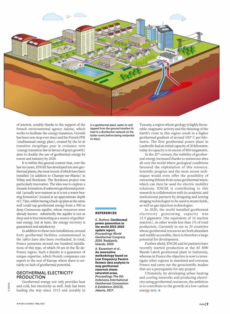
France have opted to use this energy source to heat or cool public buildings and collective hou-sing. An urban heating network is made up of one or several geothermal plants that distribute heat to users by means of a network of pipes running under the town, sometimes several kilometres long. A typical geothermal facility includes a pro-duction well and an injection well (to reinject water back into the aquifer). On the surface, heat exchangers transfer heat from the geothermal fluids to a clean water network, which in turn heats the buildings and provides domestic hot water (see figure opposite). In other words, it isn’t the same water taken from deep underground that circulates through the pipes!
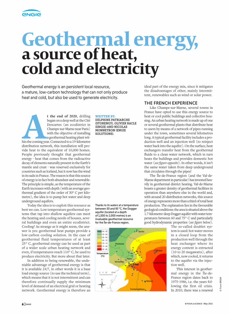
The Île-de-France region (and the Val-de-Marne department in particular) has invested hea-vily in geothermal district heating. Val-de-Marne boasts a greater density of geothermal facilities in operation than anywhere else in the world and, with around 20 distribution networks, this source of energy represents more than a third of total heat production. The explanation lies in the favourable geological conditions: the area is situated above the 1.7-kilometre-deep Dogger aquifer with water tem-peratures between 60 and 75° C and particularly good hydrodynamic properties (see figure below).
The so-called doublet sys-tem is used: hot water moves in a closed loop from the production well through the heat exchanger where its energy content is extracted (10 to 20 megawatts), after which, now cooled, it returns to the aquifer via the injec-tion well.
This interest in geother-mal energy in the Île-de-France region dates back to 1975-1986, i.e. the years fol-lowing the first oil crisis. In 2010, there was a renewal
a source of heat, cold and electricity
Thanks to its waters at a temperature between 50 and 85 °C, the Dogger aquifer (located at a depth of 1,500 to 2,000 metres) is an invaluable geothermal resource for the Île-de-France region.
WRITTEN BY:DELPHINE PATRIARCHE (STORENGY), OLIVIER RACLE (ENGIE) AND NICOLAS MONNEYRON (ENGIE SOLUTIONS).
6 ] ENGIE © POUR LA SCIENCE - May 2021
© F
rom
BR
GM
of interest, notably thanks to the support of the French environmental agency Ademe, which works to facilitate the energy transition. Growth has been non-stop ever since and the French PPE (multiannual energy plan), created by the loi de transition énergétique pour la croissance verte (energy transition law in favour of green growth) aims to double the use of geothermal energy by towns and industry by 2028.
It is within this general context that, over the last ten years, ENGIE has developed ten new geo-thermal plants, the most recent of which have been installed (in addition to Champs-sur-Marne) in Vélizy and Bordeaux. The Bordeaux project was particularly innovative. The idea was to explore a Jurassic formation of unknown geothermal poten-tial (actually non-existent as it is not a water-bea-ring formation) located at an approximate depth of 1.7 km, whilst having a back-up plan as the same well could tap geothermal energy from a 900 m deep Cretaceous aquifer, whose resources were already known. Admittedly the aquifer is not as deep and is less interesting as a source of geother-mal energy, but at least, the energy recovery is guaranteed and satisfactory.
In addition to these new installations, around forty geothermal facilities commissioned in the 1980s have also been overhauled. In total, France possesses around one hundred installa-tions of this type, of which 50 are in the Île-de-France region. Such a density is a guarantee of unique expertise, which French companies can export to the rest of Europe where there is cer-tainly no lack of geothermal potential.
GEOTHERMAL ELECTRICITY PRODUCTION
Geothermal energy not only provides heat and cold, but electricity as well. Italy has been leading the way since 1913 and notably in
Tuscany, a region whose geology is highly favou-rable: magmatic activity and the thinning of the Earth’s crust in this region result in a higher geothermal gradient of around 100° C per kilo-metre. The first geothermal power plant in Larderello had an initial capacity of 20 kilowatts: today its capacity is in excess of 800 megawatts.
In the 20th century, the visibility of geother-mal energy increased thanks to numerous sites all over the world where geological conditions favoured the exploitation of this resource. Scientific progress and the most recent tech-niques would even offer the possibility of extracting lithium from some geothermal water, which can then be used for electric mobility solutions. ENGIE is contributing to this research in collaboration with its academic and institutional partners by designing and testing imaging technologies to be used in steam fields, as well as gas injection technologies.
In 2020, the world installed geothermal electricity generating capacity was 15.9 gigawatts (the equivalent of 16 nuclear reactors), in other words less than 1% of total production. Currently in use in 29 countries whose geothermal resources are both abundant and readily accessible, there is therefore a large potential for development.
Further afield, ENGIE and its partners have recently started production at the 85 MW Murah Laboh geothermal plant in Indonesia, whereas in France the objective is now to inves-tigate other regions in mainland and overseas France and carry out the geoscientific studies that are a prerequisite for any project.
Ultimately, by developing urban heating and cooling networks and producing electri-city using geothermal resources, the ambition is to contribute to the growth of a low-carbon energy mix. n
In a geothermal plant, water (in red) tapped from the ground transfers its heat to a distribution network (in the boiler room) before being reinjected (in blue).
REFERENCES
G. Huttrer, Geothermal power generation in the world 2015-2020 update report, Proceedings World Geothermal Congress 2020, Reykjavik, Islande, 2020.
A. Kazantsev et al., An innovative methodology based on Low Frequency Passive Seismic data analysis to map geothermal reservoir steam saturated areas, Proceedings The 5th Indonesia International Geothermal Convention & Exhibition (IIGCE), Jakarta, 2017.
ENGIE [ 7 © POUR LA SCIENCE - May 2021
© E
NG
IE
RÉFÉRENCES COULEUR
24, rue Salomon de Rothschild - 92288 Suresnes - FRANCETél. : +33 (0)1 57 32 87 00 / Fax : +33 (0)1 57 32 87 87Web : www.carrenoir.com
ENGIElogotype_solid_BLUE_CMYK14/04/2015
C100%
Zone de protection 1
Zone de protection 3
Zone de protection 2
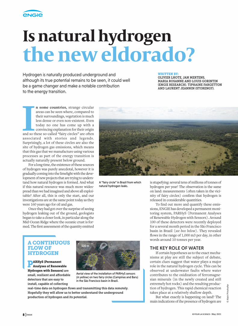
In some countries, strange circular areas can be seen where, compared to their surroundings, vegetation is much less dense or even non-existent. Even today no one has come up with a convincing explanation for their origin
and so these so-called “fairy circles” are often associated with stories and legends. Surprisingly, a lot of these circles are also the site of hydrogen gas emissions, which means that this gas that we manufacture using various processes as part of the energy transition is actually naturally present below ground.
For a long time, the existence of these sources of hydrogen was purely anecdotal, however it is gradually coming into the limelight with the deve-lopment of new projects that are trying to unders-tand how natural hydrogen is formed. And what if this natural resource was much more wides-pread than we had imagined and above all exploi-table? After all, this is only the start, and our investigations are at the same point today as they were 160 years ago for oil and gas.
Once they had got over the surprise of seeing hydrogen leaking out of the ground, geologists began to take a closer look, in particular along the Mid-Ocean Ridge where the oceanic crust is for-med. The first assessment of the quantity emitted
Is natural hydrogen the new eldorado?
WRITTEN BY: OLIVIER LHOTE, JAN MERTENS, MARIA ROSANNE AND LOUIS GORINTIN (ENGIE RESEARCH). TIPHAINE FARGETTON AND LAURENT JEANNIN (STORENGY).
is stupefying: several tens of millions of tonnes of hydrogen per year! The observation is the same on land: measurements (often taken in the vici-nity of fairy circles) confirm that hydrogen is released in considerable quantities.
To find out more and quantify these emis-sions, ENGIE has developed a permanent moni-toring system, PARHyS (Permanent Analyses of Renewable Hydrogen with Sensors). Around 100 of these detectors were recently deployed for a several month period in the São Francisco basin in Brazil (see box below). They revealed flows in the range of 1,000 m3 per day, in other words around 10 tonnes per year.
THE KEY ROLE OF WATER If certain hypotheses as to the exact mecha-
nisms at play are still the subject of debate, certain clues suggest that water plays a major role in the natural hydrogen cycle. This can be observed at underwater faults where water contributes to the oxidization of ferromagne-sian minerals (in the newly created and still extremely hot rocks) and the resulting produc-tion of hydrogen. This rapid chemical reaction takes place at a relatively shallow depth.
But what exactly is happening on land? The main indications of the presence of hydrogen are
Hydrogen is naturally produced underground and although its true potential remains to be seen, it could well be a game changer and make a notable contribution to the energy transition.
500m
A “fairy circle” in Brazil from which natural hydrogen leaks.
A CONTINUOUS FLOW OF HYDROGEN
PARHyS (Permanent Analyses of Renewable
Hydrogen with Sensors) are small, resilient and affordable detectors that are easy to install, capable of collecting real-time data on hydrogen flows and transmitting this data remotely. Hopefully they will allow us to better understand the underground production of hydrogen and its potential.
Aerial view of the installation of PARHyS sensors (in yellow) on two fairy circles (Campinas and Baru) in the São Francisco basin in Brazil.
500 m
8 ] ENGIE © POUR LA SCIENCE - May 2021
© A
lain
Prin
zho
fer
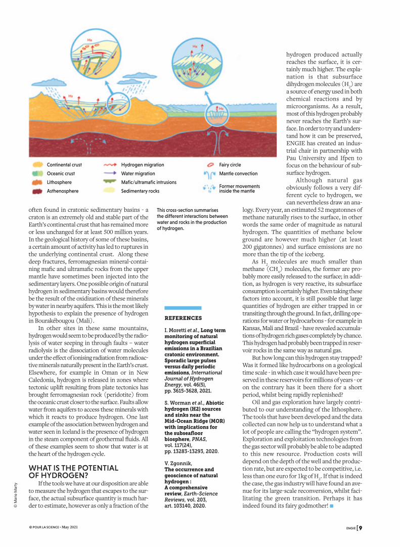
often found in cratonic sedimentary basins - a craton is an extremely old and stable part of the Earth’s continental crust that has remained more or less unchanged for at least 500 million years. In the geological history of some of these basins, a certain amount of activity has led to ruptures in the underlying continental crust. Along these deep fractures, ferromagnesian mineral-contai-ning mafic and ultramafic rocks from the upper mantle have sometimes been injected into the sedimentary layers. One possible origin of natural hydrogen in sedimentary basins would therefore be the result of the oxidization of these minerals by water in nearby aquifers. This is the most likely hypothesis to explain the presence of hydrogen in Bourakébougou (Mali).
In other sites in these same mountains, hydrogen would seem to be produced by the radio-lysis of water seeping in through faults – water radiolysis is the dissociation of water molecules under the effect of ionising radiation from radioac-tive minerals naturally present in the Earth’s crust. Elsewhere, for example in Oman or in New Caledonia, hydrogen is released in zones where tectonic uplift resulting from plate tectonics has brought ferromagnesian rock (peridotite) from the oceanic crust closer to the surface. Faults allow water from aquifers to access these minerals with which it reacts to produce hydrogen. One last example of the association between hydrogen and water seen in Iceland is the presence of hydrogen in the steam component of geothermal fluids. All of these examples seem to show that water is at the heart of the hydrogen cycle.
WHAT IS THE POTENTIAL OF HYDROGEN?
If the tools we have at our disposition are able to measure the hydrogen that escapes to the sur-face, the actual subsurface quantity is much har-der to estimate, however as only a fraction of the
REFERENCES
I. Moretti et al., Long term monitoring of natural hydrogen superficial emissions in a Brazilian cratonic environment. Sporadic large pulses versus daily periodic emissions, International Journal of Hydrogen Energy, vol. 46(5), pp. 3615-3628, 2021.
S. Worman et al., Abiotic hydrogen (H2) sources and sinks near the Mid-Ocean Ridge (MOR) with implications for the subseafloor biosphere, PNAS, vol. 117(24), pp. 13283-13293, 2020.
V. Zgonnik, The occurrence and geoscience of natural hydrogen : A comprehensive review, Earth-Science Reviews, vol. 203, art. 103140, 2020.
This cross-section summarises the different interactions between water and rocks in the production of hydrogen.
Continental crust
Oceanic crust
Lithosphere
Asthenosphere
Hydrogen migration
Water migration
Mafic/ultramafic intrusions
Sedimentary rocks
Fairy circle
Mantle convection
Former movements inside the mantle
hydrogen produced actually reaches the surface, it is cer-tainly much higher. The expla-nation is that subsurface dihydrogen molecules (H2) are a source of energy used in both chemical reactions and by microorganisms. As a result, most of this hydrogen probably never reaches the Earth’s sur-face. In order to try and unders-tand how it can be preserved, ENGIE has created an indus-trial chair in partnership with Pau University and Ifpen to focus on the behaviour of sub-surface hydrogen.
Although natural gas obviously follows a very dif-ferent cycle to hydrogen, we can nevertheless draw an ana-
logy. Every year, an estimated 52 megatonnes of methane naturally rises to the surface, in other words the same order of magnitude as natural hydrogen. The quantities of methane below ground are however much higher (at least 200 gigatonnes) and surface emissions are no more than the tip of the iceberg.
As H2 molecules are much smaller than methane (CH4) molecules, the former are pro-bably more easily released to the surface; in addi-tion, as hydrogen is very reactive, its subsurface consumption is certainly higher. Even taking these factors into account, it is still possible that large quantities of hydrogen are either trapped in or transiting through the ground. In fact, drilling ope-rations for water or hydrocarbons - for example in Kansas, Mali and Brazil - have revealed accumula-tions of hydrogen rich gases completely by chance. This hydrogen had probably been trapped in reser-voir rocks in the same way as natural gas.
But how long can this hydrogen stay trapped? Was it formed like hydrocarbons on a geological time scale - in which case it would have been pre-served in these reservoirs for millions of years - or on the contrary has it been there for a short period, whilst being rapidly replenished?
Oil and gas exploration have largely contri-buted to our understanding of the lithosphere. The tools that have been developed and the data collected can now help us to understand what a lot of people are calling the “hydrogen system”. Exploration and exploitation technologies from the gas sector will probably be able to be adapted to this new resource. Production costs will depend on the depth of the well and the produc-tion rate, but are expected to be competitive, i.e. less than one euro for 1kg of H2. If that is indeed the case, the gas industry will have found an ave-nue for its large-scale reconversion, whilst faci-litating the green transition. Perhaps it has indeed found its fairy godmother! n
ENGIE [ 9 © POUR LA SCIENCE - May 2021
© M
arie
Mar
ty

RÉFÉRENCES COULEUR
24, rue Salomon de Rothschild - 92288 Suresnes - FRANCETél. : +33 (0)1 57 32 87 00 / Fax : +33 (0)1 57 32 87 87Web : www.carrenoir.com
ENGIElogotype_solid_BLUE_CMYK14/04/2015
C100%
Zone de protection 1
Zone de protection 3
Zone de protection 2
Indium, cobalt, dysprosium, praseo-dymium and ytterbium… Although these names may sound like ancient Roman cities, they are in fact some of the elements on which the development of renewable energies depend as they
are essential components of wind turbines and solar panels, as well as different energy storage systems, in particular batteries. When produ-cing energy, these technologies do not emit greenhouse gases and their carbon footprint is a result of their manufacture, and to a lesser extent questions of maintenance and end-of-life. However, although they are promising in terms of combating climate change, other aspects are nonetheless problematic due to the use of critical metals or rare earths in their manufacture. The extraction and processing of these metals and rare earths - depending on the technology in question – can be a source of major environmental or social concerns. Examples include pollution caused by mining and/or processing, the deplorable working conditions of miners and the consequences of toxic waste on the health of local populations.
THREE CATEGORIESAt this stage, a distinction should be made
between “rare earths” and the so-called “conflict minerals” and “critical metals”. In fact, all of these categories come together in an ensemble of metals whose usage is driven by the development of technologies that are part and parcel of the energy transition.
Rare-earth elements comprise 17 metals (scandium, yttrium and the fifteen members of the lanthanide family, which include the aforementioned “Roman cities”), whose ther-mal, electrical and magnetic properties have made them indispensable for the development of energy transition and digital technologies. Their definition comes from Mendeleev and his
Towards a responsible sourcing of critical metals and rare earths
periodic table. Contrary to what their name indicates, they are not rare in absolute terms in the Earth’s crust; rare refers in fact to the small number of economically viable deposits. The term “conflict minerals” refers to minerals whose extraction conditions violate human rights, as they come from mines located in conflict zones or areas controlled by armed groups and their extraction often makes use of forced labour. The main metals in this category are tungsten, tantalum, gold and tin. Cobalt, used in batteries, is also sometimes included in this category. As for “critical metals”, the term corresponds to those elements that pre-sent supply risks (geological, technical, or geo-political) and for which a possible shortage would have major economic consequences. Conflict metals and critical metals are defined as such by nations.
Let’s take some examples. In the produc-tion of renewable energies, rare earths (mainly dysprosium, neodymium, praseodymium and gadolinum) are only used in wind turbines equipped with permanent magnets (as opposed to electromagnets). According to the BRGM, (Bureau de Recherches Géologiques et Minières), these magnets represent 20% of the consumption of rare earths by weight and 50% by value. The associated issues are not so much related to their availability as to environmental concerns. As they are only present in low concentrations, a large amount of ore must be extracted and processed, which requires large
WRITTEN BY: ANNE PRIEUR VERNAT, ENGIE LAB CRIGEN, ET ÉLODIE LE CADRE LORET, ENGIE RESEARCH
Rare earths are a group of 17 metals: scandium, yttrium and the fifteen elements in the lanthanide family (lanthanum, cerium, praseodymium, neodymium, promethium, samarium, europium, gadolinium, terbium, dysprosium, holmium, erbium, thulium, ytterbium, lutetium).
The authors thank Jo Dewulff, from the university of Ghent, for his rereading.
10 ] ENGIE © POUR LA SCIENCE - May 2021
© s
hutt
erst
ock
.co
m/S
L-Ph
oto
gra
phy
and
© s
hutt
erst
ock
.co
m/F
oxP
ictu
res
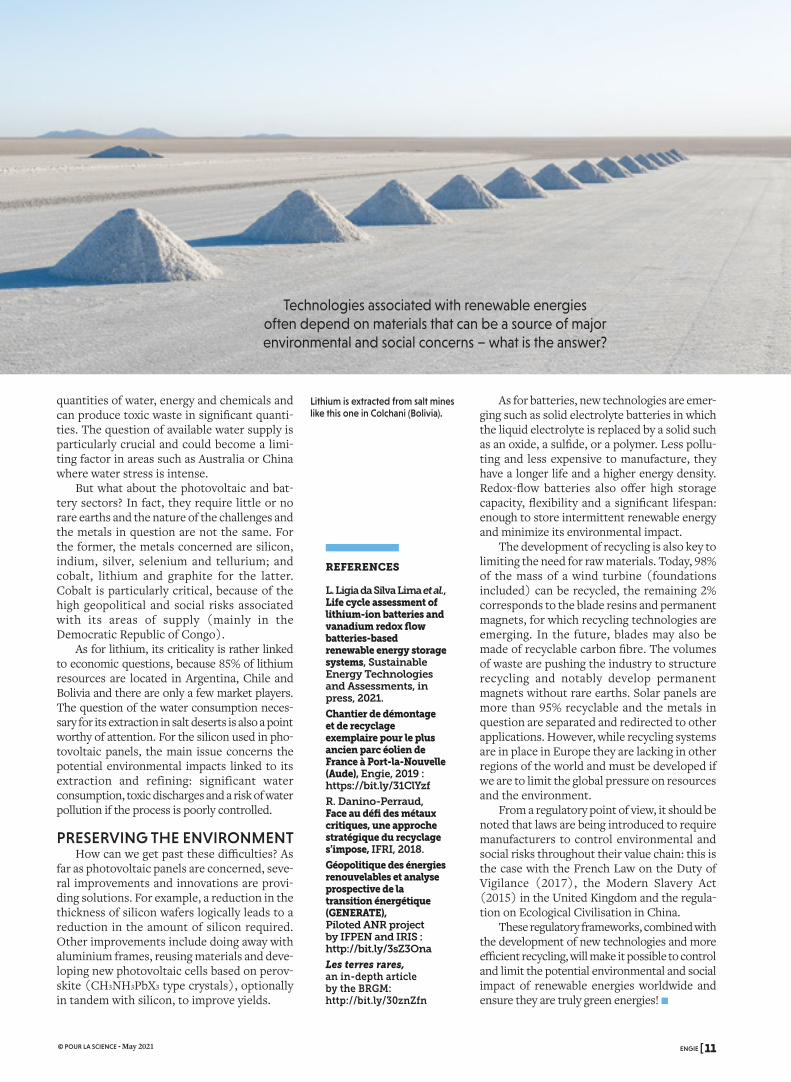
quantities of water, energy and chemicals and can produce toxic waste in significant quanti-ties. The question of available water supply is particularly crucial and could become a limi-ting factor in areas such as Australia or China where water stress is intense.
But what about the photovoltaic and bat-tery sectors? In fact, they require little or no rare earths and the nature of the challenges and the metals in question are not the same. For the former, the metals concerned are silicon, indium, silver, selenium and tellurium; and cobalt, lithium and graphite for the latter. Cobalt is particularly critical, because of the high geopolitical and social risks associated with its areas of supply (mainly in the Democratic Republic of Congo).
As for lithium, its criticality is rather linked to economic questions, because 85% of lithium resources are located in Argentina, Chile and Bolivia and there are only a few market players. The question of the water consumption neces-sary for its extraction in salt deserts is also a point worthy of attention. For the silicon used in pho-tovoltaic panels, the main issue concerns the potential environmental impacts linked to its extraction and refining: significant water consumption, toxic discharges and a risk of water pollution if the process is poorly controlled.
PRESERVING THE ENVIRONMENTHow can we get past these difficulties? As
far as photovoltaic panels are concerned, seve-ral improvements and innovations are provi-ding solutions. For example, a reduction in the thickness of silicon wafers logically leads to a reduction in the amount of silicon required. Other improvements include doing away with aluminium frames, reusing materials and deve-loping new photovoltaic cells based on perov-skite (CH3NH3PbX3 type crystals), optionally in tandem with silicon, to improve yields.
Towards a responsible sourcing of critical metals and rare earths Technologies associated with renewable energies
often depend on materials that can be a source of major environmental and social concerns – what is the answer?
As for batteries, new technologies are emer-ging such as solid electrolyte batteries in which the liquid electrolyte is replaced by a solid such as an oxide, a sulfide, or a polymer. Less pollu-ting and less expensive to manufacture, they have a longer life and a higher energy density. Redox-flow batteries also offer high storage capacity, flexibility and a significant lifespan: enough to store intermittent renewable energy and minimize its environmental impact.
The development of recycling is also key to limiting the need for raw materials. Today, 98% of the mass of a wind turbine (foundations included) can be recycled, the remaining 2% corresponds to the blade resins and permanent magnets, for which recycling technologies are emerging. In the future, blades may also be made of recyclable carbon fibre. The volumes of waste are pushing the industry to structure recycling and notably develop permanent magnets without rare earths. Solar panels are more than 95% recyclable and the metals in question are separated and redirected to other applications. However, while recycling systems are in place in Europe they are lacking in other regions of the world and must be developed if we are to limit the global pressure on resources and the environment.
From a regulatory point of view, it should be noted that laws are being introduced to require manufacturers to control environmental and social risks throughout their value chain: this is the case with the French Law on the Duty of Vigilance (2017), the Modern Slavery Act (2015) in the United Kingdom and the regula-tion on Ecological Civilisation in China.
These regulatory frameworks, combined with the development of new technologies and more efficient recycling, will make it possible to control and limit the potential environmental and social impact of renewable energies worldwide and ensure they are truly green energies! n
REFERENCES
L. Ligia da Silva Lima et al., Life cycle assessment of lithium-ion batteries and vanadium redox flow batteries-based renewable energy storage systems, Sustainable Energy Technologies and Assessments, in press, 2021.
Chantier de démontage et de recyclage exemplaire pour le plus ancien parc éolien de France à Port-la-Nouvelle (Aude), Engie, 2019 : https://bit.ly/31ClYzf
R. Danino-Perraud, Face au défi des métaux critiques, une approche stratégique du recyclage s’impose, IFRI, 2018.
Géopolitique des énergies renouvelables et analyse prospective de la transition énergétique (GENERATE), Piloted ANR project by IFPEN and IRIS : http://bit.ly/3sZ3Ona
Les terres rares, an in-depth article by the BRGM: http://bit.ly/30znZfn
Lithium is extracted from salt mines like this one in Colchani (Bolivia).
ENGIE [ 11 © POUR LA SCIENCE - May 2021
RÉFÉRENCES COULEUR
24, rue Salomon de Rothschild - 92288 Suresnes - FRANCETél. : +33 (0)1 57 32 87 00 / Fax : +33 (0)1 57 32 87 87Web : www.carrenoir.com
ENGIElogotype_solid_BLUE_CMYK14/04/2015
C100%
Zone de protection 1
Zone de protection 3
Zone de protection 2
Let’s just reflect for a moment on the movement of the waves, the incessant ebb and the flow of the tides... “What is the ocean? A prodi-gious force wasted. How stupid is the earth, to make no use of the
ocean!”, Victor Hugo lamented in Ninety-Three (1874), but his complaint is no longer relevant today as the sea has become a vital ally in our struggle to achieve a successful energy transition. In fact, according to the European Commission, the oceans could potentially deliver 100 megawatts (MW) in 2025 and 1 gigawatt (GW) by 2030, which is more than a nuclear reac-tor! But how do we go about harnessing this energy? The answer depends on its source i.e., tidal power, wave power, osmotic power or thermal energy.
TIDAL POWERThe combined gravitational forces of the
Sun, the Moon and the Earth’s rotation create tides, which in turn result in tidal streams or tidal currents (that can be very powerful) and variations in sea level. This energy can be har-nessed and converted into electricity.
Tidal currents vary periodically, moving first in one direction and then another accor-ding to a predictable rhythm that is specific to each location. As a result, it is possible to fore-cast energy availability in the long term.
Many different designs of tidal turbines are
The oceans, a whole sea of energy
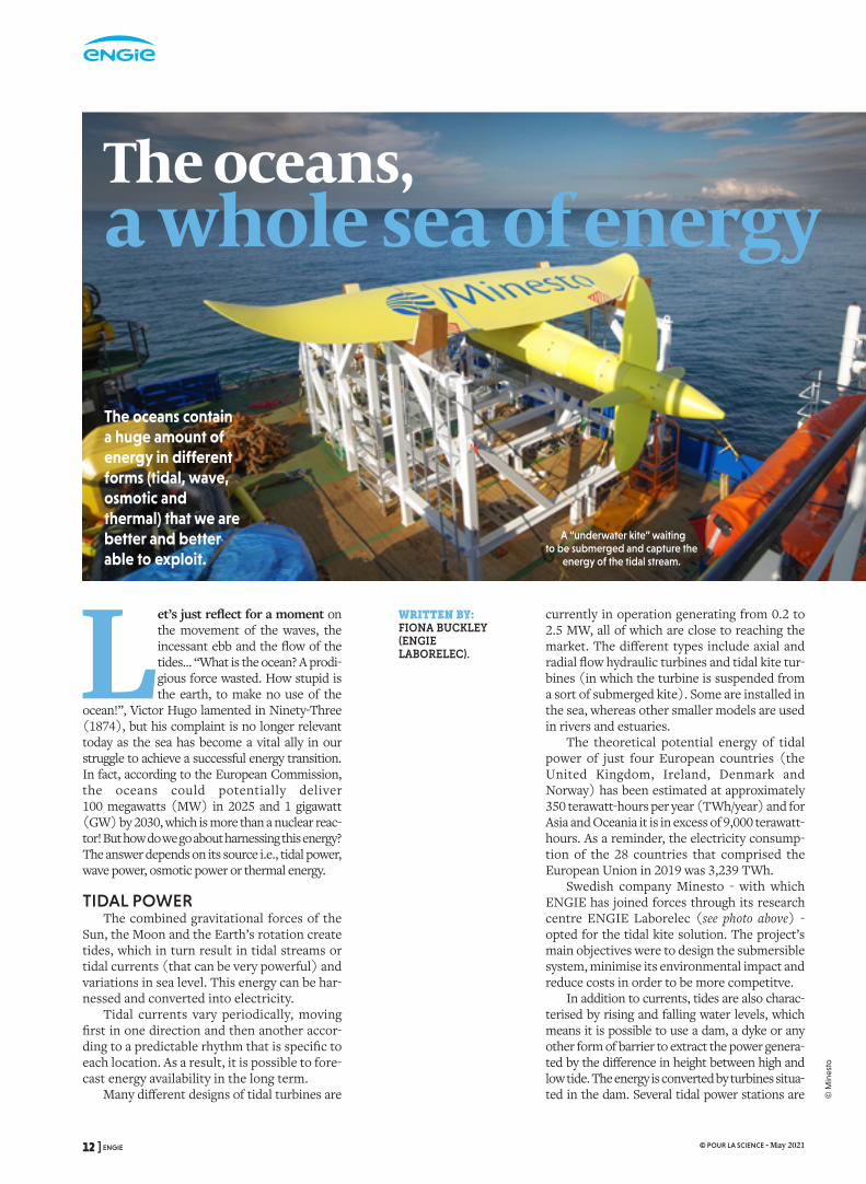
The oceans contain a huge amount of energy in different forms (tidal, wave, osmotic and thermal) that we are better and better able to exploit.
currently in operation generating from 0.2 to 2.5 MW, all of which are close to reaching the market. The different types include axial and radial flow hydraulic turbines and tidal kite tur-bines (in which the turbine is suspended from a sort of submerged kite). Some are installed in the sea, whereas other smaller models are used in rivers and estuaries.
The theoretical potential energy of tidal power of just four European countries (the United Kingdom, Ireland, Denmark and Norway) has been estimated at approximately 350 terawatt-hours per year (TWh/year) and for Asia and Oceania it is in excess of 9,000 terawatt-hours. As a reminder, the electricity consump-tion of the 28 countries that comprised the European Union in 2019 was 3,239 TWh.
Swedish company Minesto - with which ENGIE has joined forces through its research centre ENGIE Laborelec (see photo above) - opted for the tidal kite solution. The project’s main objectives were to design the submersible system, minimise its environmental impact and reduce costs in order to be more competitve.
In addition to currents, tides are also charac-terised by rising and falling water levels, which means it is possible to use a dam, a dyke or any other form of barrier to extract the power genera-ted by the difference in height between high and low tide. The energy is converted by turbines situa-ted in the dam. Several tidal power stations are
WRITTEN BY: FIONA BUCKLEY (ENGIE LABORELEC).
A “underwater kite” waiting to be submerged and capture the
energy of the tidal stream.
12 ] ENGIE © POUR LA SCIENCE - May 2021
© M
ines
to

already in activity around the world, notably in France (240 MW), Canada (20 MW), China (5 MW) and South Korea (254 MW). Worldwide, the theoretical potential energy is estimated at 80 GW, however this technology requires large investments and its environmental impact needs to be carefully examined.
WAVE POWER AND THERMAL ENERGY
When the wind blows over the oceans, part of its energy is transferred to the waves it creates. Wave energy converters are devices that harness this energy that varies from one season to ano-ther and which is only available for short periods of time. We can distinguish between nine families of devices capable of converting this kinetic energy into electricity. In Porto de Pecém (north-eastern Brazil), ENGIE has taken part in the ins-tallation of two point absorbers, floating structures connected to the land by metallic arms that activate hydraulic pumps as they rise and fall. Other examples include an oscillating water column, a sort of vertical piston activated by the movements of the waves that has been tested recently off the coast of Bilbao and which is part of the Opera project financed by the European Union and supported by ENGIE.
There are currently more than 100 pilot pro-jects and demonstrators with a capacity of between 0.125 and 1 MW. For several countries in the north and south of Europe that boast long stretches of coast, the theoretical potential energy is an estimated 2,628 TWh/year, whereas for Asia and Oceania it reaches 12,000 TWh/year.
But even if the sea is calm, there is still the ocean’s thermal energy to be exploited. The basic principle is as follows: warm surface water passes through a heat exchanger where its heat vaporises a working fluid (or the seawater itself is evaporated) and the expan-ding vapour is used to power a turbine. Deeper cold water is then used to condense the vapour. OTEC (Ocean Thermal Energy Conversion) technology is only pertinent in subtropical zones where the difference in temperature between the surface and the depths is greater than 20° C. Several hurdles remain to be over-come, notably the size of the hydraulic pipe network - a 100 MW plant would require 1,000 m of cold water pipes measuring some 10 metres in diameter! -, as well as improving heat exchanger efficiency.
The power of the oceans can also be used for cooling buildings. Seawater Air Conditioning makes use of the difference in temperature between shallow and deep water. The advan-tages are twofold – it is both economical and environmentally friendly - because not only does SWAC replace traditional air-conditioning systems, it reduces the corresponding electri-cal consumption by up to 80 %.
ENGIE’s Thassalia project in Marseille is a good example (see photo above). A seawater heating and cooling network provides the connected buil-dings with a rate of renewable energy use in excess of 75 % and guarantees competitive and stable tariffs. Water drawn out of the port at a depth of 7 metres is directly fed through reversible heat pumps and high-efficiency chilling units; the ins-tallation covers the needs of 600,000 m2 of buil-dings in the Euroméditerranée business district.
OSMOTIC POWER The final source of marine energy is osmotic
power that results from the difference in salt concentration between two liquids. Two types of technology are currently being studied: Pressure Retarded Osmosis (PRO) and Reversed Electrodialysis (RED). The former is based on the movement of freshwater towards saltwater (osmosis) through a membrane, which creates an increase in pressure on the saltwater side. This pressure can be converted into electricity by a turbine. The latter relies on the transport of ions through ion exchange membranes; the chemical potential difference due to the different salt concen-tration of saltwater and freshwater generates a vol-tage over the membrane, rather like a salt battery.
Notwithstanding the fact that these methods are still in their infancy and many challenges remain to be faced, the potential capacity of osmo-tic power is an estimated 647 GW. ENGIE (through its subsidiary Tractebel Energia) toge-ther with Coppe research centre at the Federal University of Rio de Janeiro, has taken part in a pilot project to develop a small-scale membrane.
The diversity of marine energy outlined above is promising. More reliable than sun or wind power and with a high potential in both Europe and worldwide, it is likely that it will make an important contribution to the new energy mix that will result from the energy transition. To this end, we have to wait until these technologies are more commercially mature and competitive, whilst studying their environmental impact in order to assure that they are sustainable in the long term. The ocean will then no longer be “a prodigious force wasted”. n
The Thassalia project in Marseille (France) is a seawater district heating and cooling system that services 600,000 m2 of buildings.
ENGIE [ 13 © POUR LA SCIENCE - May 2021
© E
NG
IE

RÉFÉRENCES COULEUR
24, rue Salomon de Rothschild - 92288 Suresnes - FRANCETél. : +33 (0)1 57 32 87 00 / Fax : +33 (0)1 57 32 87 87Web : www.carrenoir.com
ENGIElogotype_solid_BLUE_CMYK14/04/2015
C100%
Zone de protection 1
Zone de protection 3
Zone de protection 2
A demonstration at Niagara Falls in the United States put an end to the “War of the Currents” that opposed Thomas Edison, a staunch defender of direct current
(DC) for the transmission and distribution of electricity and Nikola Tesla, who advocated alternating current (AC). The latter came out victorious and today alternating current is still transmitted through the electrical grid. However, the advent of renewable energies could change the game and give direct cur-rent another chance. In addition to electri-city, every other energy network including those transporting gas and heat is concerned by this revolution that is a consequence of the energy transition.
Today these networks – which are often invisible because they are underground - connect consumers to (usually centralised) energy-producing plants. This vital infrastruc-ture must adapt to accompany the energy sector towards a carbon neutral future, but the ques-tions raised by this evolution highlight the urgent need for technological innovations. As wind and solar farms increasingly produce direct current, is it interesting to continue transmitting electricity in the form of alterna-ting current? Amongst the various low-carbon gases, hydrogen has the wind in its sails, but can it be injected into the existing gas grid? Is it pos-sible to make district heating (and cooling) networks even more sustainable than today?
Solutions do exist, however as these sys-tems are complex and often made up of infrastructures developed over decades, these questions can only be answered by adopting a nuanced approach. Let’s take a look at a few examples in relation to the aforementioned questions.
The energy network revolutionEnergy transmission and distribution networks, whether electricity, gas, or heat - and which are often underground - must adapt to meet the needs of the energy transition.
Nikola Tesla won the “War of the Currents” because it is relatively easy to convert alterna-ting current to higher or lower voltages by using a transformer. In this way electricity in the form of high voltage alternating current (HVAC) can be transmitted over long dis-tances with minimal losses. However, the land-scape of energy production has changed: photovoltaic cells produce direct current and the AC production of wind turbine generators, whose speed of rotation varies, is unstable and therefore does not comply with the standard grid frequency of 50 hertz. To correct this defect, the energy passes through a power conversion system made up of a rectifier and an inverter and is converted to direct current at one step in the process.
DIRECT CURRENT GETS ITS SECOND CHANCE
Batteries storing electricity for mobility solutions, portable electronic devices and grid services all operate on direct current as well, and all our electronic equipment also runs on DC. In parallel to this expanding offer and demand for direct current, power electronics, i.e., “energy conversion electronics” has become a mature technology and it is easy to convert DC to AC. At the end of the day, the main reason for the original choice of alterna-ting current is now redundant.
Greater distances between the installations where renewable energy is produced and stored
WRITTEN BY: MURÈS ZAREA, ENGIE RESEARCH, WOUTER VANCOETSEM, ENGIE LABORELEC, ISABELLE ALLIAT AND CRISTIAN MURESAN, ENGIE LAB CRIGEN
14 ] ENGIE © POUR LA SCIENCE - May 2021
© M
ijnw
ater
, Hee
rlen
and the population centres where it is consu-med will require new electricity connections. Despite the potential increase in cost, under-ground cables should be preferred to overhead lines if technically feasible.
More than 125 years after the victory of alternating current for grid usage, power elec-tronics technologies are now making it possible to transmit electricity effectively in the form of a high voltage direct current (HVDC) system, also called a “power superhighway” and the-reby provide an alternative to HVAC. HVDC transmissions systems have even several advantages when it comes to long underground or submarine cables, which could be the only way to connect offshore installations.
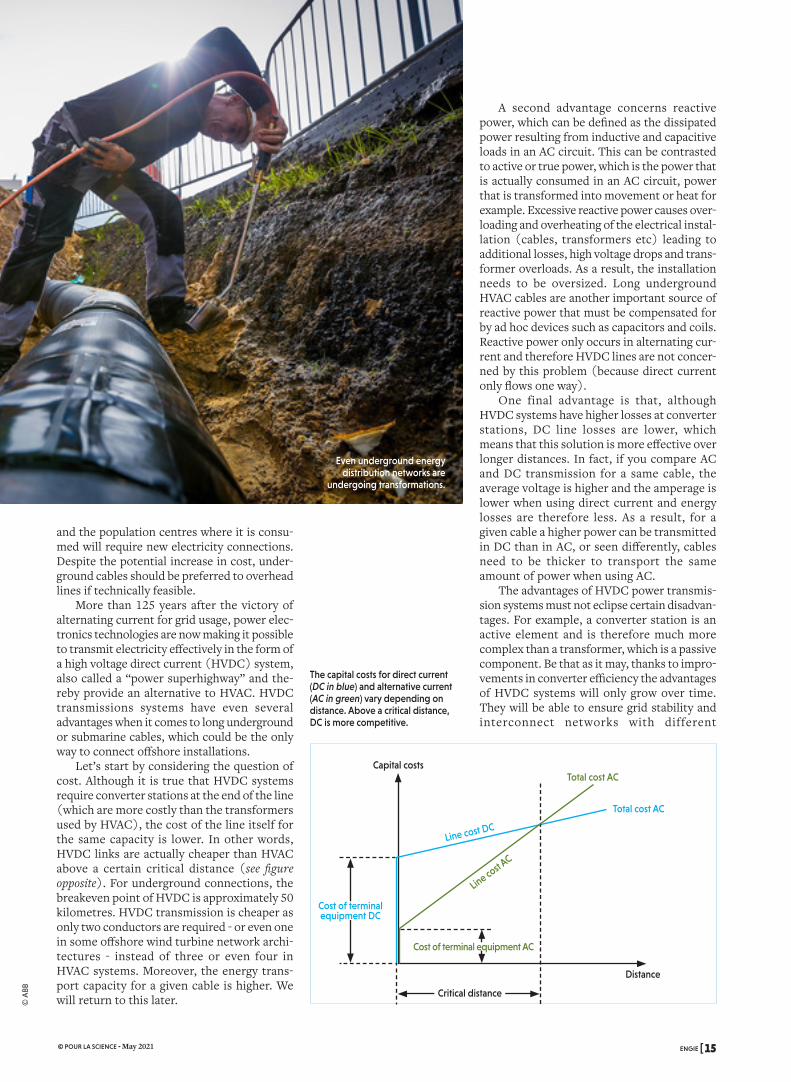
Let’s start by considering the question of cost. Although it is true that HVDC systems require converter stations at the end of the line (which are more costly than the transformers used by HVAC), the cost of the line itself for the same capacity is lower. In other words, HVDC links are actually cheaper than HVAC above a certain critical distance (see figure opposite). For underground connections, the breakeven point of HVDC is approximately 50 kilometres. HVDC transmission is cheaper as only two conductors are required - or even one in some offshore wind turbine network archi-tectures - instead of three or even four in HVAC systems. Moreover, the energy trans-port capacity for a given cable is higher. We will return to this later.
A second advantage concerns reactive power, which can be defined as the dissipated power resulting from inductive and capacitive loads in an AC circuit. This can be contrasted to active or true power, which is the power that is actually consumed in an AC circuit, power that is transformed into movement or heat for example. Excessive reactive power causes over-loading and overheating of the electrical instal-lation (cables, transformers etc) leading to additional losses, high voltage drops and trans-former overloads. As a result, the installation needs to be oversized. Long underground HVAC cables are another important source of reactive power that must be compensated for by ad hoc devices such as capacitors and coils. Reactive power only occurs in alternating cur-rent and therefore HVDC lines are not concer-ned by this problem (because direct current only flows one way).
One final advantage is that, although HVDC systems have higher losses at converter stations, DC line losses are lower, which means that this solution is more effective over longer distances. In fact, if you compare AC and DC transmission for a same cable, the average voltage is higher and the amperage is lower when using direct current and energy losses are therefore less. As a result, for a given cable a higher power can be transmitted in DC than in AC, or seen differently, cables need to be thicker to transport the same amount of power when using AC.
The advantages of HVDC power transmis-sion systems must not eclipse certain disadvan-tages. For example, a converter station is an active element and is therefore much more complex than a transformer, which is a passive component. Be that as it may, thanks to impro-vements in converter efficiency the advantages of HVDC systems will only grow over time. They will be able to ensure grid stability and interconnect networks with different
Even underground energy distribution networks are
undergoing transformations.
Capital costs
Line cost DC
Line cost AC
Total cost AC
Total cost AC
Cost of terminal equipment DC
Critical distance
Distance
Cost of terminal equipment AC
The capital costs for direct current (DC in blue) and alternative current (AC in green) vary depending on distance. Above a critical distance, DC is more competitive.
ENGIE [ 15 © POUR LA SCIENCE - May 2021
© A
BB

RÉFÉRENCES COULEUR
24, rue Salomon de Rothschild - 92288 Suresnes - FRANCETél. : +33 (0)1 57 32 87 00 / Fax : +33 (0)1 57 32 87 87Web : www.carrenoir.com
ENGIElogotype_solid_BLUE_CMYK14/04/2015
C100%
Zone de protection 1
Zone de protection 3
Zone de protection 2
frequencies and characteristics. However, HVDC will never replace HVAC which has advantages of its own. HVDC is a complemen-tary technical solution for new underground cables transmitting electricity over long distances.
GAS AND HYDROGENThese electricity cables will run alongside
the pipes that comprise the gas grid. Biomethane will gradually be blended with natural gas, and hydrogen (H2) could also be added to the mix. During the winter peak period, two or three times more gas energy is consumed than electrical energy: decarboni-zing gas is therefore a top priority. To this end, in addition to biomethane, green hydrogen (or at least low-carbon hydrogen) is one option, a fact illustrated by the ambi-tious production strategies in Germany, France and the Netherlands. A part of this new energy carrier could be produced near major consumers, whereas the rest would be transported and distributed locally to end consumers via the existing gas grid. However, the specific properties of H2 raise some ques-tions as to its transport.
First of all, compared to natural gas the small size of H2 molecules leads to different interactions
with materials – steel, polyethylene, polymers – used in the existing network and installations. Numerous research and development projects are currently studying the compatibility of these materials with H2, taking operating conditions - notably pressure and variations thereof (see box below) - into consideration.
It has been noted that steel pipes with cer-tain metallurgical characteristics are some-times fragil ized by H2 (hydrogen embrittlement). This phenomenon also depends on the operating conditions in an infrastructure that was, of course, initially intended just for natural gas.
The compressor stations around the grid are also a source of added constraints: due to the thermodynamics of H2, these centrifugal compressors would need to be modified, as would the gas turbines that drive them. For example, at levels of hydrogen in excess of 5-10 %, some of the turbine’s burners would need to be changed as the combustion charac-teristics of H2 are very different to those of natural gas. In addition, some small compo-nents made of elastomer (which is sensitive to hydrogen) would probably need to be replaced. However modern distribution networks that use high density polyethylene are perfectly compatible with H2 and do not use
WATER, GAS AND HYDROGEN IN EVERY ROOM
Cappelle-la-Grande near Dunkirk (France). The GRHYD demonstrator has confirmed the
viability of injecting hydrogen (H2) from renewable sources into the natural gas distribution grid. As the grid in question was originally designed for natural gas, its capacity to safely distribute a mix of hydrogen and natural gas was initially confirmed by a series of tests in the laboratory on the
different elements that comprise the network (meters, detectors etc), as well as for end-use applications. Once the compatibility of every part of the network with H2 had been verified, the administrative authorisations (ministerial decree dated 22nd June 2016) required to implement this innovative system were granted. The trial ran for 22 months with a gradual increase in the quantity of H2
blended into the natural gas (up to 20 % by volume). The technical feedback received validated the feasibility of the concept in a new gas distribution network supplying 103 new homes. The demonstrator has injected approximately 14,000 m3 of H2 produced using 112 gigawatt-hours of electricity from renewable sources. This has resulted in a saving of 150 megawatt-hours of natural gas per year. In addition, the carbon
footprint of the mix supplied to the homes has been reduced: injecting 20 % green H2 by volume reduces greenhouse gas emissions by 7 % (a figure explained by the fact that the energy density of H2 is three times lower than that of natural gas).The success of the GRHYD demonstrator paves the way for using H2 as a means of integrating renewable energies in gas distribution.
REFERENCES
The EU-funded THyGA project: https://thyga-project.eu
The European Hydrogen Backbone concept: https://bit.ly/31hZeED
In Cappelle-la-Grande near Dunkirk (France), a new 103-home housing estate is supplied with a mix of natural gas and 20 % hydrogen.
16 ] ENGIE © POUR LA SCIENCE - May 2021
© E
ngie
/A. M
eyss
oni
er

compressors either. We must nevertheless make sure that the various “accessories” throu-ghout the grid (valves, pressure reducers and meters etc) are also compatible.
Finally in terms of usage, natural gas boilers are certified for a natural gas/H2 mix up to a hydrogen content of 23 %, which facilitates the direct injection of the latter into the grid. The EU-funded THyGA project is systematically exploring the impact of blending hydrogen and natural gas on different domestic and commercial end uses.
These various elements provide a rather disparate perspective. If we want to minimise the number of modifications in the short term, it would be possible to inject H2 into the distri-bution network as recent distribution networks can deal with blends containing approximately 20 % H2 by volume (compared to just 5 % to 10 % for gas transport networks). Transport networks could evolve in two dis-tinct directions, either we make do with only transporting compatible mixes using the exis-ting infrastructures, or we adapt them so they can transport higher proportions of H2 (and in so doing make them compatible with pure hydrogen in the future). This option is cur-rently being studied as part of the European Hydrogen Backbone (EHB) initiative as a way of connecting large supply and demand centres across Europe.
Electricity, gas and heat going hand in hand even closer together than before
As far as small consumers are concerned, a known solution for reducing community car-bon footprints consists in improving district heating and cooling networks by introducing decentralised renewable energy sources (renewable electricity, green gas and green hydrogen), recovering waste heat (surplus heat that has been produced and which would
otherwise be lost), as well as increasing self-consumption and local energy storage.
A convergence of this sort on a local level becomes a reality with fifth genera-tion district heating and cooling systems (abbrevia-ted to 5GDHC). Let’s remind ourselves of the suc-cessive generations. The three first systems consisted in distributing extremely hot water (around or above 100° C) in pipes that were first made of concrete, fol-
lowed by non-insulated steel pipes and finally insulated steel pipes. Water temperatures were reduced in the fourth generation to around 60°C. The latest generation, 5GDHC, is a low-temperature network for both heating and coo-ling that associates numerous energy sources (see figure opposite).
5TH GENERATION NETWORKSThanks to the synergy between different
energy infrastructures, 5GDHC networks encourage the creation of Local Energy Communities (LOC) in which prosumers (i.e., consumers who are also producers) share both the investment costs and the bene-fits. LOCs based on 5GDHC can overcome the problem of seasonal peaks in demand and enable an economic model based on energy trading between communities and the electri-city and gas markets.
Smart digital management systems are an indispensable part of these new networks, in particular to enhance the real-time manage-ment of multi-energy systems, optimise their operation and ensure the traceability of energy transactions. Such a system could make use of blockchain technology (a decen-tralised peer-to-peer system for storing and transmitting information).
These examples demonstrate the need for energy distribution networks – whether they are transporting electricity, a low-carbon gas such as hydrogen or heat - to evolve for a suc-cessful energy transition. Numerous innova-tions will be necessary, some which are already underway and others are yet to come. And of course, we must reconcile Thomas Edison and Nikola Tesla! n
Wind energy
Energy distribution
Solar energy
Smart energy management system
Transmission and distribution
Electrical energy storage
Thermal energy storage
Heat pump
Hydrogen production
Electric car
Gas networkElectricity network
Heating network
Hydrogen car
Biomass conversion
Centralised production of electricity and heat
The fifth generation of district heating and cooling systems (5GDHC) associates many different types of energy sources.
ENGIE [ 17 © POUR LA SCIENCE - May 2021
© U
niv.
de
Twen
te

RÉFÉRENCES COULEUR
24, rue Salomon de Rothschild - 92288 Suresnes - FRANCETél. : +33 (0)1 57 32 87 00 / Fax : +33 (0)1 57 32 87 87Web : www.carrenoir.com
ENGIElogotype_solid_BLUE_CMYK14/04/2015
C100%
Zone de protection 1
Zone de protection 3
Zone de protection 2
Today, energy is stored underground in France, mainly as natural gas. Tomorrow, renewable energy will be stored in the same way.
Underground Energy Storage
WRITTEN BY:PAULE LABAUNE AND PIERRE HENNEBELLE (STORENGY), LIONEL NADAU (CRIGEN) AND DOMINIQUE CORBISIER (LABORELEC)
ENGIE Campus, the group’s future headquarters in La Garenne-Colombes near Paris, will be equipped
with a heating and cooling system based on the underground storage of heat in an aquifer.
Salt deposits Deep aquifers
have a surface area of several square kilometres, but are no more than a few dozen metres thick. Today in France, there are 10 natural gas storage sites in aquifers and they represent an approximate capacity of 120,000 GWh.
Man-made, salt caverns are mined in existing salt deposits between several dozen to several hun-dred metres thick. A well is drilled into the forma-tion and water is pumped down to dissolve the salt, which returns to the surface as brine. This process creates caverns that are structurally sound and, as rock salt is impermeable, they can be used to store both gas and non-aqueous liquids (such as oil). In France, there are four natural gas storage sites with
around fifty salt caverns between 50,000 and 600,000 cubic metres in size and with a total storage capacity of 12,000 GWh. This type of installation has a lot of poten-tial for storing non-fossil energy.
RENEWABLE ENERGYWe could notably envisage storing
biogas (whose production is on the rise) instead of natural gas. The MéthyCentre project located in Angé (in the Loir-et-Cher department) combines a Power-to-Gas unit and a methanation plant that produces biogas from agricultural waste.
Salt deposits and aquifers in France
The annual consumption of natural gas in France is around 500,000 gigawatt hours (GWh), which is the equivalent of the production of 70 nuclear reac-tors. You probably think that
the gas arrives straight from a pipeline or a gas tanker, but that is not the case. More than half of the gas supplied in winter actually comes from underground storage sites and the same is true for heating oil and petrol.
This decades-old, proven technology provides a safe and low-cost solution for storing very large volumes of fuel with a minimal footprint above ground. As far as natural gas is concerned, this massive storage is indispensable, especially for balancing the gas demand throughout the year. In France, the available storage capacity is spread across 14 sites around the country and characte-rised by two geological formations: porous rock and salt caverns (see figure opposite).
In the first type of reservoir, the gas is stored in a porous rock stratum, such as sandstone or limestone, which is capped by a layer of imper-meable rock. Such a site may be a former oil or gas deposit, or an aquifer (as is often the case in France). These reservoirs located at a depth of several hundred metres below the ground typically
18 ] ENGIE © POUR LA SCIENCE - May 2021
© E
NG
IE
© IN
ERIS

A methanation process also recycles the CO2 from the biogas and combines it with hydrogen to produce synthetic methane. Up to 2,200 GWh of gas is injected into the gas grid per year (with a target of 56,000 GWh by 2030); part of it is stored at a nearby site in Céré-la-Ronde.
Hydrogen alone or combined with natural gas can also be stored in salt caverns. This has been the case since the 1970s in the United Kingdom and since the 1980s in the USA. In France, the HYPSTER pro-ject (Hydrogen Pilot Storage for Large Ecosystem Replication) launched in 2020 plans to test the storage of up to 44 tonnes of green hydrogen (or 1.8 GWh) in salt caverns. This corres-ponds to the daily consumption of more than 1,700 hydrogen fuel cell buses. Aquifers are less suited to storing hydrogen, because of the possible presence, depending on the chemical characteris-tics of the water and the type of rock that com-prises the reservoir, of hydrogen-consuming bacteria. As the volumetric energy density of hydrogen is lower than natural gas (it is the oppo-site in terms of mass), at usual storage pressures, converting all of France’s salt caverns to store hydrogen would correspond to just 3,500 GWh.
In flow batteries, two chemical compounds (electrolytes) flow through one or more elec-trochemical cells, where a chemical reaction on both sides of an ion-exchange membrane pro-duces electricity. In France and Germany, stu-dies are focussing on how to combine flow batteries with the massive storage potential of salt caverns (for the organic electrolytes). There are still many obstacles to overcome, notably the compatibility of these organic com-pounds with brine and the salt cavern walls, nevertheless a first 0.7 GWh battery should be operational in Germany by 2023. Devoting all the salt cavern storage in France to this use would store around 60 GWh.
As for compressed air (the term used is Compressed Air Energy Storage, or CAES), the available storage space ranges from 40 to 130 GWh. When released, the compressed air would be used to drive a turbine generator.
Finally, storing electricity in a pumped sto-rage power plant (PSPP) would yield approxi-
mately 15 GWh. A PSPP stores electricity using a similar system to that of pumped-storage hydroelec-tricity: water is pumped up to a reservoir at a higher eleva-tion and produces electricity as it travels back down through turbines to the lower (underground in this case) reservoir.
STORING HEATBut would it be pos-
sible to store heat instead of gas or liquid? UTES (Underground Thermal Energy Storage) aims to
answer this question and such systems could contribute to the heating and cooling of indi-vidual homes or several buildings.
A first option is an open-loop system: ATES (the A stands for aquifer). Water is extracted from an aquifer located at a depth of between 40 and 300 metres; in summer, the water is used for cooling and then the heated groundwater is re-injected back into the aquifer. In winter, the pre-viously heated water is extracted and, in combination with a heat pump, used for heating purposes. This type of heat storage system is already widespread in the Netherlands and Sweden, but it is still rare in France. ENGIE will be installing one of the first ones in France at its new headquarters in La Garenne-Colombes, near Paris (see figure opposite).
In a BTES (B for Borehole) system, heat exchange takes place within a closed loop in boreholes drilled down into the underlying rock formation.
All things considered, in the short-term salt caverns would appear to be an effective solution for storing renewable energy. They are actually being tested, as part of projects at different stages of maturity, for the storage of synthetic methane, hydrogen and compressed air, and as part of a flow battery system. In the longer term, storage in porous formations will also have a role to play, provided that remaining technical and environ-mental issues can be solved.
To ensure the success of the energy transi-tion and, in particular, to overcome the inter-mittent nature of renewable energy production, effective storage solutions are surely indispen-sable - and if they could be underground, i.e. invisible, that would be even better! n
Salt caverns are the most promising technique for storing renewable energies underground
CH41 200
350
1361,5
H2
Compressed air
Flow battery
Pumping station
A 600,000 m3 cavern at a depth of 1,500 metres
The quantity of energy stored in a 600,000 m3 cavern depends on the energy carrier in question.
REFERENCE
The Storengy YouTube channel: youtube.com/channel/UCGXpFQsIrl45vd-5285G82NA
ENGIE [ 19 © POUR LA SCIENCE - May 2021
RÉFÉRENCES COULEUR
24, rue Salomon de Rothschild - 92288 Suresnes - FRANCETél. : +33 (0)1 57 32 87 00 / Fax : +33 (0)1 57 32 87 87Web : www.carrenoir.com
ENGIElogotype_solid_BLUE_CMYK14/04/2015
C100%
Zone de protection 1
Zone de protection 3
Zone de protection 2
French Environment ministers may come and go – in February 2021, Barbara Pompili took over from Francois de Rugy, who had been
minister since June 2019 – however the message remains the same: it is vital that we develop wind power and notably off-shore wind power. Of course, if we hope to reach our objectives in terms of redu-cing greenhouse gases this method of producing renewable electricity must indeed be a cornerstone of our energy strategy, however, this solution has to overcome the same challenges that face every other type of renewable energy. Above all it must be flexible, in other words be able to balance supply and demand and secure the energy supply. Storage provides a way of meeting this problem, but that begs the question: where do we store the surplus energy?
You need space to store electricity and if you take population growth into account, you’ll get a better idea of what is at stake. Let’s take an example. An underground salt cavern measuring 600,000 m3
(the equivalent of three Arc de Triomphes) fil-led with compressed air or hydrogen for the daily consumption of 265,000 households (13 gigawatt hours) would have a footprint of 2.25 hectares. If you included the batteries that would be needed for each home, the total sur-face area required would be 9.92 hectares. Even if new battery technologies reduce this impact, we will need to find a way of using less space.
INSIDE OR OUT?One idea consists in storing electricity in
the sea next to or near the offshore wind tur-bines that are producing it. This would also not only reduce the cost of connecting offshore wind farms to the grid, it would also conside-rably improve the flexibility of the power sys-tem. Finally, storing energy locally would be an ideal solution for the floating wind turbines of the future, which will be located further from the coast. Such wind farms are flexible, inde-pendent from the grid, better suited to the constraints of shipping and reduce the impact of visual pollution.
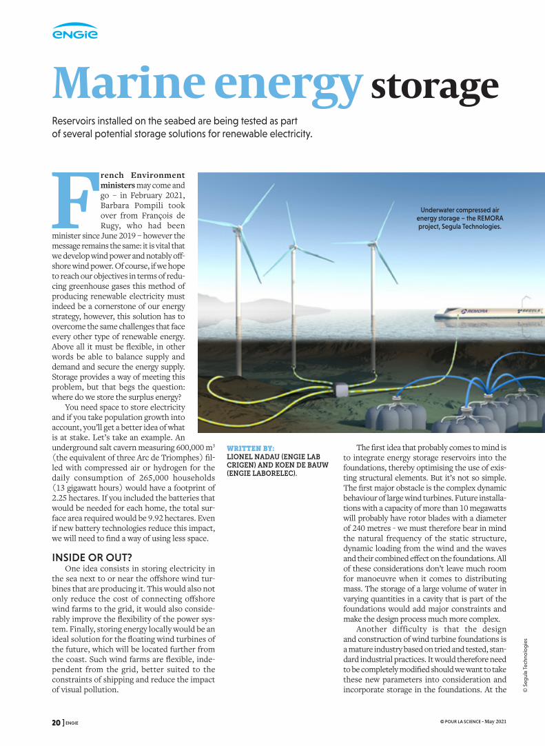
Marine energy storageReservoirs installed on the seabed are being tested as part of several potential storage solutions for renewable electricity.
The first idea that probably comes to mind is to integrate energy storage reservoirs into the foundations, thereby optimising the use of exis-ting structural elements. But it’s not so simple. The first major obstacle is the complex dynamic behaviour of large wind turbines. Future installa-tions with a capacity of more than 10 megawatts will probably have rotor blades with a diameter of 240 metres - we must therefore bear in mind the natural frequency of the static structure, dynamic loading from the wind and the waves and their combined effect on the foundations. All of these considerations don’t leave much room for manoeuvre when it comes to distributing mass. The storage of a large volume of water in varying quantities in a cavity that is part of the foundations would add major constraints and make the design process much more complex.
Another difficulty is that the design and construction of wind turbine foundations is a mature industry based on tried and tested, stan-dard industrial practices. It would therefore need to be completely modified should we want to take these new parameters into consideration and incorporate storage in the foundations. At the
WRITTEN BY: LIONEL NADAU (ENGIE LAB CRIGEN) AND KOEN DE BAUW (ENGIE LABORELEC).
Underwater compressed air energy storage – the REMORA project, Segula Technologies.
20 ] ENGIE © POUR LA SCIENCE - May 2021
© S
egul
a Te
chno
log
ies

end of the day, both wind tur-bine designers and certification bodies are hesitant to commit to this solution.
Such constraints would be even more important for floa-ting wind turbines mounted on structures like floating barges. In this case, large variations in the mass of the anchoring sys-tem would have an even greater impact on overall behaviour. In addition, integrating large empty spaces designed to contain a sizeable volume of sea water or compressed air into the foundations would lead to addi-tional constraints, for example
in terms of wall thickness and corrosion protec-tion. The final stumbling block is that the develop-ment of floating wind turbines is still in its infancy.
Some projects are trying to meet these chal-lenges, one example being the FLASC prototype that consists in a storage system and a floating platform equipped with either a wind turbine, solar panels or any other system producing electricity. Others have chosen a more autonomous approach, opting for a remote storage solution and installing purpose-built structures on the seabed at a dis-tance from the wind farm. Such solutions are more likely to find their way onto the market.
AIR AT THE BOTTOM OF THE SEA Amongst the various storage technologies
that are under study today, two are already at an advanced stage: underwater compressed air energy storage (UCAES) and underwater pum-ped hydroelectric energy storage (UPHES). Both are well suited to conditions at sea and able to store large quantities of energy.
One example of the first technology is Remora, which is developed by Segula Technologies. It consists of a boat-like floating
platform housing a high-performance hydraulic compression system, which is paired with concrete tanks on the seabed to store the compressed air (see opposite page). Its operation can be divided into three stages: water is injected by a hydraulic pump into a chamber filled with air; the chamber fills with water com-pressing the air; once the target pressure has been reached, the compressed air is injected into underwater storage tanks. But how is the electricity generated?
When electricity is required, the chambers are filled with water and then compressed air from the tanks is injected to push the water out through a turbine. Electricity production stops when the air tanks are empty. The water used by this storage system helps limit the heat gai-
ned by the air during the compression phase and cools it during expansion. Thanks to this thermal ally, the electricity yield reaches 70 % compared to about 40 % for other similar systems. It is inte-resting to note that this type of storage can also be used for solar farms installed near the coast.
THE SEA FROM TOP TO BOTTOM The second example is StEnSea (Storing
Energy at Sea), a project developed by the Fraunhofer Institute for Energy Economics and Energy System Technology in Kassel (Germany). It works along the same lines as pumped hydroelectric energy storage (PHES), a type of hydroelectric installation comprising two interconnected reservoirs located one above the other. The capacity of the installa-tion is determined by the difference in eleva-tion between the two and the quantity of energy stored in a given volume of water. When electricity demand is low, water is pumped to the upper reservoir; when demand is high, the water is released and travels back down passing through turbines to generate electricity.
In the StEnSea project, the upper storage reservoir is actually the sea itself and hollow concrete spheres on the seabed comprise the lower reservoir. These concrete spheres measu-ring some 30 metres in diameter contain a pump and a turbine coupled to a generator (see above). The throughput capacity of the installation depends on the height of the water column, whereas storage capacity depends on the num-ber of spheres. Each of the latter can contain 20 megawatt-hours of electricity, in other words the daily consumption of 400 French house-holds. During the storage phase, water is pum-ped out of the sphere and during the production phase water flows back in, driving a turbine and producing electricity.
These two technologies have already proved their effectiveness, so perhaps one day we will see such structures proliferate on the ocean floor. n
REFERENCE
É. Le Cadre Loret et al., Emerging sustainable technologies, report from 2020 Technology watch, 2020 : https://bit.ly/3tgjcM9
A pumped hydroelectric energy storage plant specially adapted to
underwater usage
Storage Electricity
Production
ENGIE [ 21 © POUR LA SCIENCE - May 2021
© F
raun
hofe
r

RÉFÉRENCES COULEUR
24, rue Salomon de Rothschild - 92288 Suresnes - FRANCETél. : +33 (0)1 57 32 87 00 / Fax : +33 (0)1 57 32 87 87Web : www.carrenoir.com
ENGIElogotype_solid_BLUE_CMYK14/04/2015
C100%
Zone de protection 1
Zone de protection 3
Zone de protection 2
When kites produce energy
How can we harness the considerable energy of high-altitude winds? Thanks to airborne wind turbines tethered to a cable.
As part of its project, SkySails has developed an airborne wind
turbine that can adapt to different uses: on land, offshore and on mobile
structures such as cargo ships.
Winds that can be harnessed by a classic wind turbine at an altitude of 100 metres (left) are much weaker than those accessible by an airborne wind turbine at an altitude of 250 metres (right).
© M
akan
i
In 1833, the utopian inventor John Adolphus Etzler dreamt of how tech-nology would free the world from labour and poverty, notably by harnes-sing the energy of high-altitude winds. In the 19th century, his ideas seemed
more fiction than science, however this solu-tion is under consideration today because it may well provide a way of getting round the problems facing traditional horizontal axis wind turbines (HAWT).
The idea is to put a wind turbine in the air. In airborne wind energy (AWE), a flying device such as a kite anchored to the earth by a cable operates at high altitude, where the winds are stronger and steadier. ENGIE understands the strategic impor-tance of AWE: not only do these next generation wind turbines hold the promise of an extremely low environmental impact, they also offer a subs-tantial reduction in the levelized cost of energy (LCOE) i.e., the cost of producing electricity com-pared to other energy sources. But what exactly makes them so different?
First of all, without the enor-mous masts and rotors of tradi-tional wind turbines or their heavy foundations, AWE sys-tems need up to 95 % less mate-rials, whilst guaranteeing a similar energy yield. As a result, capital costs are much lower - as is the carbon footprint - and these systems are easier to install in regions lacking the necessary
infrastructure. In addition, their streamlined struc-tures mean less visual impact, whilst enabling them to be deployed in distant and difficult to access locations both onshore and in the open sea.
HIGHER AND STRONGER Another advantage is improved energy yield.
At altitude, wind speeds are higher and condi-tions are more persistent, which helps to com-pensate for the intermittent nature of renewable energy and contributes to lowering the cost of electricity. In addition, the hoped-for load factor (the ratio between actual electricity production and the amount that would have been produced had the wind turbine been working at full nomi-nal capacity for the entire period) is between 50 and 80 %, compared to 40 to 55 % for an offshore wind turbine and 20 to 40 % for an onshore wind turbine. Finally, studies being carried out on the winds around the world (see below) suggest that AWE would make new, large-scale energy resources accessible.
WRITTEN BY:OLIVIER VAN OOST (ENGIE LABORELEC) AND ROB VERSTEIRT (ENGIE RESEARCH).
Wind speed (metres per second)
6 7 8 9 10
22 ] ENGIE © POUR LA SCIENCE - May 2021

© A
. Che
rub
ini e
t al.Generator
ElectricityElectricity
Mechanical energy Mechanical energy
Turbine
Flying device equipped with a turbine
Flying deviceInflatable
device
Wind WindWindCab
le
Cable
Cable
What will these airborne wind turbines look like? Several very different designs are under review, all of which are still at an early stage in their development. So far, none stand out from the crowd. Their characteristics are determined by market requirements, notably transportability and simplicity, the strength of winds they are designed to harvest and their output capacity (from several tens of kilowatts up to several megawatts). Designers are currently concentra-ting on the first real pilot projects that aim to demonstrate the reliability, performance and autonomy of their chosen solutions and their ability to be scaled up. To date, the nameplate capacity of prototypes that have already proved their worth is between 2 and 600 kW and increases of up to 3 MW are anticipated.
Although there is a wide array of different concepts, we can distinguish between two types of energy production: on-board generation (fly-gen) and ground generation (ground-gen). In the for-mer, which has mainly been studied and developed in the United States, the flying device (kite, drone, plane etc) is equipped with propellers whose rota-tion generates electricity, which is then transpor-ted to the ground via the cable tethering the device. In the second option, which is more often chosen in Europe, the conversion of mechanical energy into electricity is carried out by generators instal-led on the ground. The flying device pulls on the tether causing it to unwind from its drum, the rotation of which drives the generator. We can easily imagine whole groups of kites arranged in an AWE farm or a carousel configuration. The main disadvantage of this second option is the intermit-tent nature of energy production: energy is pro-duced as the kite’s lift causes the tether to reel out, after which it has to be retracted so that the pro-cess can start over again. These pumping or yoyo-like cycles last between 30 seconds and six minutes depending on wind conditions.
Most of these concepts have proven that they are pertinent, however numerous hurdles remain to be overcome if airborne wind energy is to become a reality: long term reliability (at least 20 years), fully automated launching and landing, onboard power supply, overall efficiency (wing optimization, energy conversion and storage etc) and whether the device can be scaled up. As part of its desire to encourage the development of AWE technologies, ENGIE has assessed
numerous projects, notably those of EnerKite, TwingTec and SkySails (see photo page 22).
ON LAND OR AT SEA?So, where is the best place to deploy these
airborne wind turbines, offshore or onshore? Installation on land is easier from a technical point of view, but it could be hindered if the necessary authorisations cannot be obtained. A promising alternative (considering its great potential for wind power) would therefore be the development of offshore installations on floating structures. As ENGIE sees it, such solu-tions are particularly well suited to developing deep water, offshore wind power in locations far from large port infrastructures (where both fixed and floating HAWT systems are difficult to install and operate competitively). In this res-pect, there are three decisive arguments in favour of installing AWE systems offshore: they can be operated from lightweight, floating plat-forms, sea winds are stronger and there is cer-tainly no lack of space. Intermediary locations are also possible, for example to provide an auxiliary energy source onboard a cargo ship.
Once the proof of concept has been esta-blished, different AWE systems can be geared to ENGIE’s various target markets: small-scale, decentralised wind energy facilities (from 100 to 500 kilowatts), large-scale centralised wind energy facilities (from 500 kW to several MW) and offshore wind energy facilities. Whatever the case, AWE should be considered as being complementary to traditional, centralised wind farms, whether on land or offshore and should not be put into competition with other renewable energy technologies.
If there do not seem to be any unsurmountable technical problems, it is because the main obstacles to rolling out and operating AWE systems on a large scale lie elsewhere. In fact, as airborne wind tur-bines are flying devices, problems of licences, avia-tion regulations and social acceptance could constitute important limiting factors.
AWE is nevertheless a breakthrough techno-logy that is totally in phase with the needs of the energy transition. It seems very promising, even if it’s in the long term. One thing’s for sure, it will be in operation well before the world ima-gined by John Adolphus Etzler comes to pass and work becomes a thing of the past. n
REFERENCE
P. Weiss, Airborne wind energy prepares for Take-Off, Engineering, vol. 6(2), pp. 107-109 2020.
There are a wide variety of airborne wind turbines. Electricity can be generated onboard a flying device equipped with a generator (left), or on the ground using a generator driven by the cable that tethers the flying device (right).
ENGIE [ 23 © POUR LA SCIENCE - May 2021
© M
akan
i
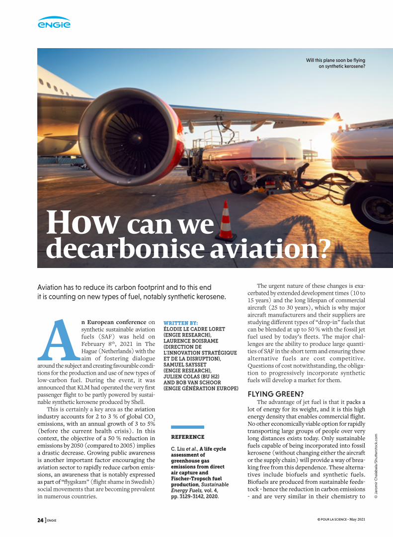
RÉFÉRENCES COULEUR
24, rue Salomon de Rothschild - 92288 Suresnes - FRANCETél. : +33 (0)1 57 32 87 00 / Fax : +33 (0)1 57 32 87 87Web : www.carrenoir.com
ENGIElogotype_solid_BLUE_CMYK14/04/2015
C100%
Zone de protection 1
Zone de protection 3
Zone de protection 2
A n European conference on synthetic sustainable aviation fuels (SAF) was held on February 8th, 2021 in The Hague (Netherlands) with the aim of fostering dialogue
around the subject and creating favourable condi-tions for the production and use of new types of low-carbon fuel. During the event, it was announced that KLM had operated the very first passenger flight to be partly powered by sustai-nable synthetic kerosene produced by Shell.
This is certainly a key area as the aviation industry accounts for 2 to 3 % of global CO2 emissions, with an annual growth of 3 to 5% (before the current health crisis). In this context, the objective of a 50 % reduction in emissions by 2050 (compared to 2005) implies a drastic decrease. Growing public awareness is another important factor encouraging the aviation sector to rapidly reduce carbon emis-sions, an awareness that is notably expressed as part of “flygskam” (flight shame in Swedish) social movements that are becoming prevalent in numerous countries.
Aviation has to reduce its carbon footprint and to this end it is counting on new types of fuel, notably synthetic kerosene.
The urgent nature of these changes is exa-cerbated by extended development times (10 to 15 years) and the long lifespan of commercial aircraft (25 to 30 years), which is why major aircraft manufacturers and their suppliers are studying different types of “drop-in” fuels that can be blended at up to 50 % with the fossil jet fuel used by today’s fleets. The major chal-lenges are the ability to produce large quanti-ties of SAF in the short term and ensuring these alternative fuels are cost competitive. Questions of cost notwithstanding, the obliga-tion to progressively incorporate synthetic fuels will develop a market for them.
FLYING GREEN? The advantage of jet fuel is that it packs a
lot of energy for its weight, and it is this high energy density that enables commercial flight. No other economically viable option for rapidly transporting large groups of people over very long distances exists today. Only sustainable fuels capable of being incorporated into fossil kerosene (without changing either the aircraft or the supply chain) will provide a way of brea-king free from this dependence. These alterna-tives include biofuels and synthetic fuels. Biofuels are produced from sustainable feeds-tock - hence the reduction in carbon emissions - and are very similar in their chemistry to
WRITTEN BY: ÉLODIE LE CADRE LORET (ENGIE RESEARCH), LAURENCE BOISRAME (DIRECTION DE L’INNOVATION STRATÉGIQUE ET DE LA DISRUPTION), SAMUEL SAYSSET (ENGIE RESEARCH), JULIEN COLAS (BU H2) AND BOB VAN SCHOOR (ENGIE GÉNÉRATION EUROPE)
REFERENCE
C. Liu et al., A life cycle assessment of greenhouse gas emissions from direct air capture and Fischer-Tropsch fuel production, Sustainable Energy Fuels, vol. 4, pp. 3129-3142, 2020.
How can we decarbonise aviation?
Will this plane soon be flying on synthetic kerosene?
24 ] ENGIE © POUR LA SCIENCE - May 2021
© J
aro
mir
Cha
lab
ala/
Shut
ters
tock
.co
m
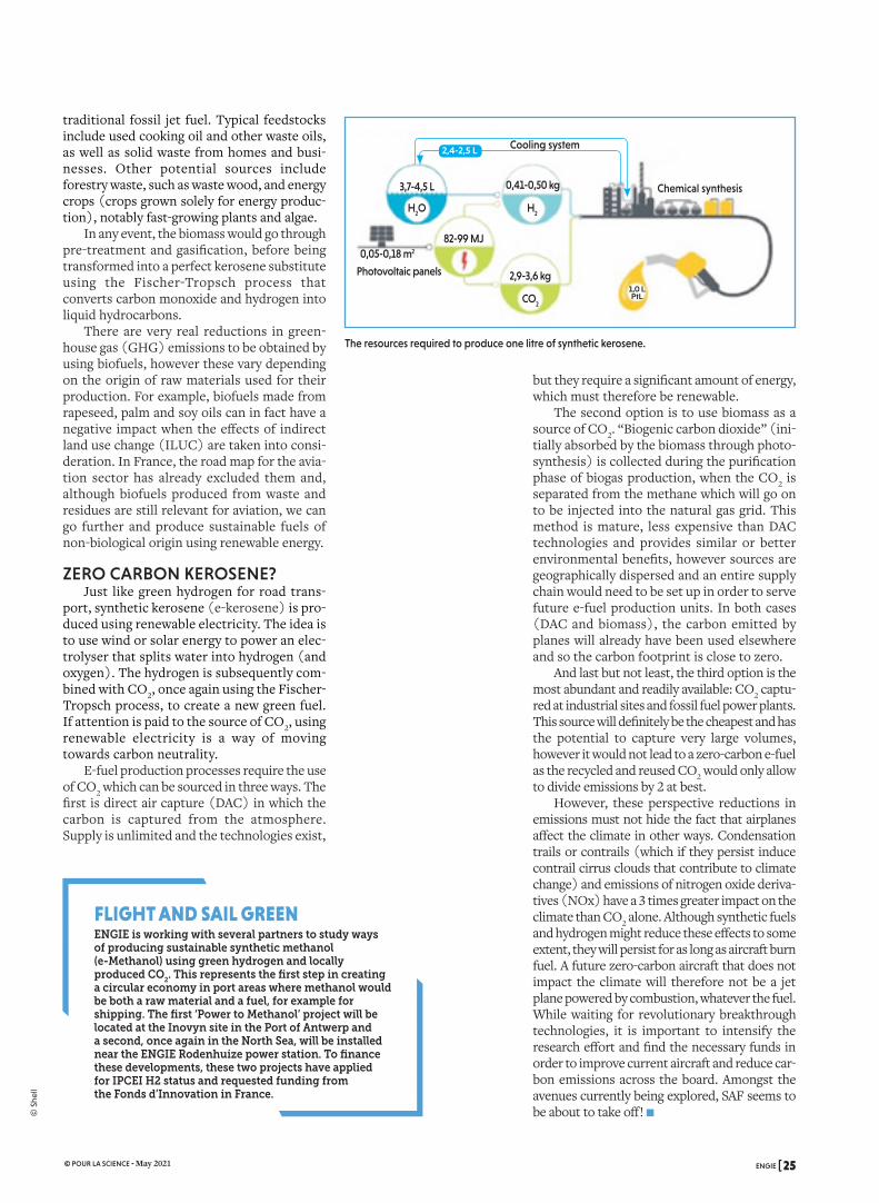
but they require a significant amount of energy, which must therefore be renewable.
The second option is to use biomass as a source of CO2. “Biogenic carbon dioxide” (ini-tially absorbed by the biomass through photo-synthesis) is collected during the purification phase of biogas production, when the CO2 is separated from the methane which will go on to be injected into the natural gas grid. This method is mature, less expensive than DAC technologies and provides similar or better environmental benefits, however sources are geographically dispersed and an entire supply chain would need to be set up in order to serve future e-fuel production units. In both cases (DAC and biomass), the carbon emitted by planes will already have been used elsewhere and so the carbon footprint is close to zero.
And last but not least, the third option is the most abundant and readily available: CO2 captu-red at industrial sites and fossil fuel power plants. This source will definitely be the cheapest and has the potential to capture very large volumes, however it would not lead to a zero-carbon e-fuel as the recycled and reused CO2 would only allow to divide emissions by 2 at best.
However, these perspective reductions in emissions must not hide the fact that airplanes affect the climate in other ways. Condensation trails or contrails (which if they persist induce contrail cirrus clouds that contribute to climate change) and emissions of nitrogen oxide deriva-tives (NOx) have a 3 times greater impact on the climate than CO2 alone. Although synthetic fuels and hydrogen might reduce these effects to some extent, they will persist for as long as aircraft burn fuel. A future zero-carbon aircraft that does not impact the climate will therefore not be a jet plane powered by combustion, whatever the fuel. While waiting for revolutionary breakthrough technologies, it is important to intensify the research effort and find the necessary funds in order to improve current aircraft and reduce car-bon emissions across the board. Amongst the avenues currently being explored, SAF seems to be about to take off! n
FLIGHT AND SAIL GREENENGIE is working with several partners to study ways of producing sustainable synthetic methanol (e-Methanol) using green hydrogen and locally produced CO2. This represents the first step in creating a circular economy in port areas where methanol would be both a raw material and a fuel, for example for shipping. The first ‘Power to Methanol’ project will be located at the Inovyn site in the Port of Antwerp and a second, once again in the North Sea, will be installed near the ENGIE Rodenhuize power station. To finance these developments, these two projects have applied for IPCEI H2 status and requested funding from the Fonds d’Innovation in France.
The resources required to produce one litre of synthetic kerosene.
traditional fossil jet fuel. Typical feedstocks include used cooking oil and other waste oils, as well as solid waste from homes and busi-nesses. Other potential sources include forestry waste, such as waste wood, and energy crops (crops grown solely for energy produc-tion), notably fast-growing plants and algae.
In any event, the biomass would go through pre-treatment and gasification, before being transformed into a perfect kerosene substitute using the Fischer-Tropsch process that converts carbon monoxide and hydrogen into liquid hydrocarbons.
There are very real reductions in green-house gas (GHG) emissions to be obtained by using biofuels, however these vary depending on the origin of raw materials used for their production. For example, biofuels made from rapeseed, palm and soy oils can in fact have a negative impact when the effects of indirect land use change (ILUC) are taken into consi-deration. In France, the road map for the avia-tion sector has already excluded them and, although biofuels produced from waste and residues are still relevant for aviation, we can go further and produce sustainable fuels of non-biological origin using renewable energy.
ZERO CARBON KEROSENE?Just like green hydrogen for road trans-
port, synthetic kerosene (e-kerosene) is pro-duced using renewable electricity. The idea is to use wind or solar energy to power an elec-trolyser that splits water into hydrogen (and oxygen). The hydrogen is subsequently com-bined with CO2, once again using the Fischer-Tropsch process, to create a new green fuel. If attention is paid to the source of CO2, using renewable electricity is a way of moving towards carbon neutrality.
E-fuel production processes require the use of CO2 which can be sourced in three ways. The first is direct air capture (DAC) in which the carbon is captured from the atmosphere. Supply is unlimited and the technologies exist,
Photovoltaic panels
3,7-4,5 L
82-99 MJ
2,4-2,5 L
0,05-0,18 m2
2,9-3,6 kg
0,41-0,50 kg
H2
H2O
CO2
1,0 L PtL
Cooling system
Chemical synthesis
ENGIE [ 25 © POUR LA SCIENCE - May 2021
© S
hell
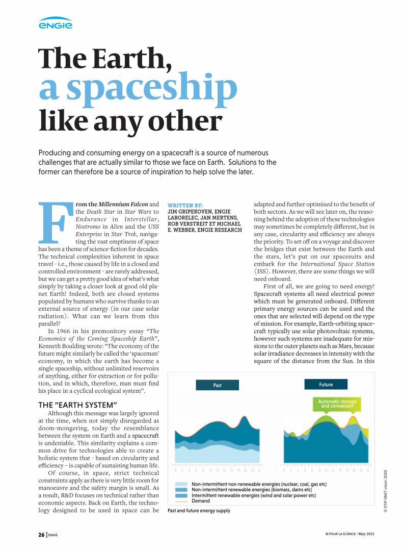
RÉFÉRENCES COULEUR
24, rue Salomon de Rothschild - 92288 Suresnes - FRANCETél. : +33 (0)1 57 32 87 00 / Fax : +33 (0)1 57 32 87 87Web : www.carrenoir.com
ENGIElogotype_solid_BLUE_CMYK14/04/2015
C100%
Zone de protection 1
Zone de protection 3
Zone de protection 2
From the Millennium Falcon and the Death Star in Star Wars to Endurance in Interstellar, Nostromo in Alien and the USS Enterprise in Star Trek, naviga-ting the vast emptiness of space
has been a theme of science-fiction for decades. The technical complexities inherent in space travel - i.e., those caused by life in a closed and controlled environment - are rarely addressed, but we can get a pretty good idea of what’s what simply by taking a closer look at good old pla-net Earth! Indeed, both are closed systems populated by humans who survive thanks to an external source of energy (in our case solar radiation). What can we learn from this parallel?
In 1966 in his premonitory essay “The Economics of the Coming Spaceship Earth”, Kenneth Boulding wrote: “The economy of the future might similarly be called the ‘spaceman’ economy, in which the earth has become a single spaceship, without unlimited reservoirs of anything, either for extraction or for pollu-tion, and in which, therefore, man must find his place in a cyclical ecological system”.
THE “EARTH SYSTEM”Although this message was largely ignored
at the time, when not simply disregarded as doom-mongering, today the resemblance between the system on Earth and a spacecraft is undeniable. This similarity explains a com-mon drive for technologies able to create a holistic system that - based on circularity and efficiency – is capable of sustaining human life.
Of course, in space, strict technical constraints apply as there is very little room for manoeuvre and the safety margin is small. As a result, R&D focuses on technical rather than economic aspects. Back on Earth, the techno-logy designed to be used in space can be
The Earth, a spaceship like any otherProducing and consuming energy on a spacecraft is a source of numerous challenges that are actually similar to those we face on Earth. Solutions to the former can therefore be a source of inspiration to help solve the later.
adapted and further optimised to the benefit of both sectors. As we will see later on, the reaso-ning behind the adoption of these technologies may sometimes be completely different, but in any case, circularity and efficiency are always the priority. To set off on a voyage and discover the bridges that exist between the Earth and the stars, let’s put on our spacesuits and embark for the International Space Station (ISS). However, there are some things we will need onboard.
First of all, we are going to need energy! Spacecraft systems all need electrical power which must be generated onboard. Different primary energy sources can be used and the ones that are selected will depend on the type of mission. For example, Earth-orbiting space-craft typically use solar photovoltaic systems, however such systems are inadequate for mis-sions to the outer planets such as Mars, because solar irradiance decreases in intensity with the square of the distance from the Sun. In this
WRITTEN BY:JIM GRIPEKOVEN, ENGIE LABORELEC, JAN MERTENS, ROB VERSTREIT ET MICHAEL E. WEBBER, ENGIE RESEARCH
Past and future energy supply
Past Future
Automatic storage and conversion
Non-intermittent non-renewable energies (nuclear, coal, gas etc)Non-intermittent renewable energies (biomass, dams etc)Intermittent renewable energies (wind and solar power etc) Demand
26 ] ENGIE © POUR LA SCIENCE - May 2021
© E
TIP-
SNET
vis
ion
2050

case, spacecraft powered by radioisotope power systems (RPS) are preferable; they do not depend on the Sun and are highly reliable, which is important for autonomous operations such as the rovers exploring the surface of Mars.
To colonise the Moon, nuclear fission is considered the best option. On site, the various installations and equipment (from “accommo-dation” to the larger rovers) could be equipped with fuel cells, which convert the che-mical energy contained in hydrogen (H2) and oxygen (O2) into electricity. Fuel cells have already proven their worth on the Apollo mis-sions and the Space Shuttle programme and moreover they produce (drinkable) water as a by-product of their operation, which is obviously vital to keeping the astro-nauts alive. The similarities between energy systems on Earth and in space lie in some of the main challenges they are facing, notably sustainability, energy efficiency and intermit-tent resources.
BACK ON EARTH Let’s take the example of the satellites, spa-
cecraft and space stations orbiting the Earth. Their energy is supplied by solar arrays
(backed up by lithium-ion batteries to cover the periods when they enter the Earth’s sha-dow). This can be compared to the current situation of power generation on Earth, where
the increasing amount of intermittent renewable energy sources requires a back-up solution for the periods during which the wind does not blow or the sun does not shine. This flexible on-demand power generation can be delivered by thermal power plants, but batteries are also rapidly gai-ning importance.
Storage solutions also have a role to play. Energy is stored in periods of excess renewable electricity genera-tion and is subsequently used to make up for periods during which renewable electricity generation does not cover the demand (see
figure page 26). Smart energy management systems can predict demand, manage produc-tion and optimise the grid.
Today, most Earth-orbiting spacecraft rely on advanced solar cells with an efficiency around 30 %, which is higher than the effi-ciency of those used in the best performing commercially available solar panels on Earth (22-24 %). Could we imagine a transfer of technology between space and our planet? It’s
The economy of the future might similarly be called the ‘spaceman’ economy, in which the earth has become a single spaceship
Two spacecraft, the ISS and the Earth, two closed systems populated by humans who survive thanks to an external source of energy, the Sun.
ENGIE [ 27 © POUR LA SCIENCE - May 2021
© s
hutt
erst
ock
.co
m/D
ima
Zel
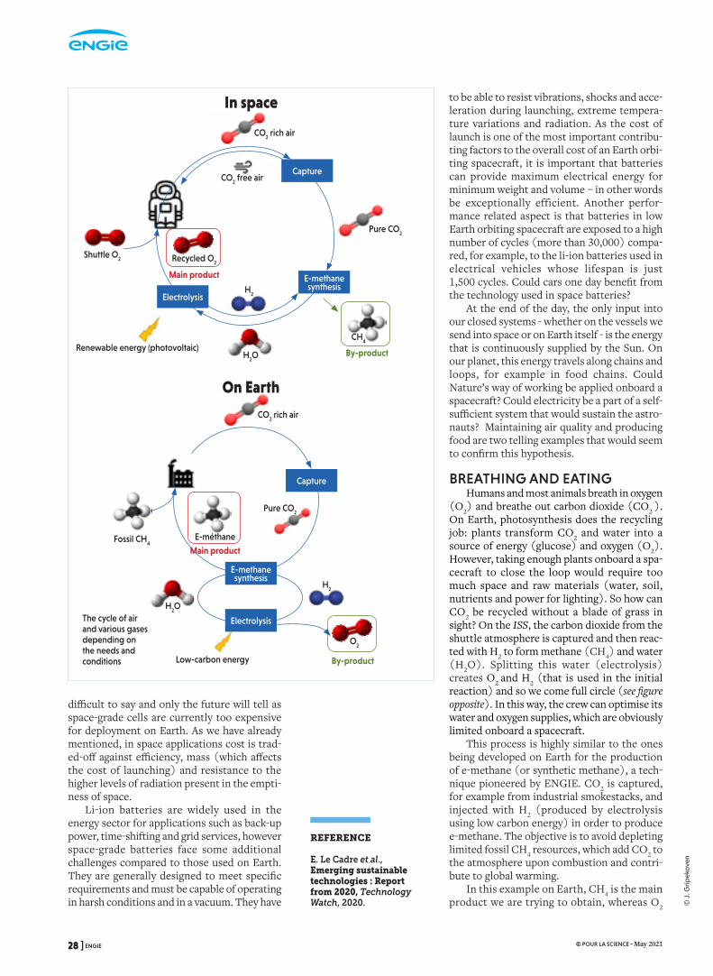
RÉFÉRENCES COULEUR
24, rue Salomon de Rothschild - 92288 Suresnes - FRANCETél. : +33 (0)1 57 32 87 00 / Fax : +33 (0)1 57 32 87 87Web : www.carrenoir.com
ENGIElogotype_solid_BLUE_CMYK14/04/2015
C100%
Zone de protection 1
Zone de protection 3
Zone de protection 2
difficult to say and only the future will tell as space-grade cells are currently too expensive for deployment on Earth. As we have already mentioned, in space applications cost is trad-ed-off against efficiency, mass (which affects the cost of launching) and resistance to the higher levels of radiation present in the empti-ness of space.
Li-ion batteries are widely used in the energy sector for applications such as back-up power, time-shifting and grid services, however space-grade batteries face some additional challenges compared to those used on Earth. They are generally designed to meet specific requirements and must be capable of operating in harsh conditions and in a vacuum. They have
to be able to resist vibrations, shocks and acce-leration during launching, extreme tempera-ture variations and radiation. As the cost of launch is one of the most important contribu-ting factors to the overall cost of an Earth orbi-ting spacecraft, it is important that batteries can provide maximum electrical energy for minimum weight and volume – in other words be exceptionally efficient. Another perfor-mance related aspect is that batteries in low Earth orbiting spacecraft are exposed to a high number of cycles (more than 30,000) compa-red, for example, to the li-ion batteries used in electrical vehicles whose lifespan is just 1,500 cycles. Could cars one day benefit from the technology used in space batteries?
At the end of the day, the only input into our closed systems - whether on the vessels we send into space or on Earth itself - is the energy that is continuously supplied by the Sun. On our planet, this energy travels along chains and loops, for example in food chains. Could Nature’s way of working be applied onboard a spacecraft? Could electricity be a part of a self-sufficient system that would sustain the astro-nauts? Maintaining air quality and producing food are two telling examples that would seem to confirm this hypothesis.
BREATHING AND EATING Humans and most animals breath in oxygen
(O2) and breathe out carbon dioxide (CO2 ). On Earth, photosynthesis does the recycling job: plants transform CO2 and water into a source of energy (glucose) and oxygen (O2). However, taking enough plants onboard a spa-cecraft to close the loop would require too much space and raw materials (water, soil, nutrients and power for lighting). So how can CO2 be recycled without a blade of grass in sight? On the ISS, the carbon dioxide from the shuttle atmosphere is captured and then reac-ted with H2 to form methane (CH4) and water (H2O). Splitting this water (electrolysis) creates O2 and H2 (that is used in the initial reaction) and so we come full circle (see figure opposite). In this way, the crew can optimise its water and oxygen supplies, which are obviously limited onboard a spacecraft.
This process is highly similar to the ones being developed on Earth for the production of e-methane (or synthetic methane), a tech-nique pioneered by ENGIE. CO2 is captured, for example from industrial smokestacks, and injected with H2 (produced by electrolysis using low carbon energy) in order to produce e-methane. The objective is to avoid depleting limited fossil CH4 resources, which add CO2 to the atmosphere upon combustion and contri-bute to global warming.
In this example on Earth, CH4 is the main product we are trying to obtain, whereas O2
REFERENCE
E. Le Cadre et al., Emerging sustainable technologies : Report from 2020, Technology Watch, 2020.
The cycle of air and various gases depending on the needs and conditions
On Earth
In space
CO2 rich air
CO2 rich air
Pure CO2
Pure CO2
CO2 free air
Shuttle O2
H2O
H2
H2
Recycled O2
O2
Renewable energy (photovoltaic)
Low-carbon energy
Main product
Main product
By-product
By-product
CH4
Capture
E-methane synthesis
Electrolysis
Fossil CH4
E-méthane
H2O
Capture
E-methane synthesis
Electrolysis
28 ] ENGIE © POUR LA SCIENCE - May 2021
© J
. Grip
eko
ven

is seen as a by-product that is mostly vented. While using a similar system, the reasoning behind what happens on the ISS is completely different! Nevertheless, a common goal of both processes is to increase overall effi-ciency, for example by using higher perfor-mance materials, such as metal-organic frameworks or MOFs (highly porous, poly-mer structures), for capturing CO2 and new catalysts for the produc-tion of e-methane. Another avenue of improvement is to better inte-grate the different steps, for example using the heat produced in the methanation reactor to cover the needs in heat required to cap-ture CO2 and thereby improve the efficiency of the process.
PUTTING BACTERIA ON THE MENU
In space, breathing is one thing, but eating is another! Astronauts on the ISS eat pre-packaged foods and new sup-plies are shipped every 90 days. Longer and more distant missions would therefore be a source of new problems as, for example, any food consumed on the return trip from Mars would have been produced 5 to 7 years earlier! To avoid food spoilage and carrying a heavy payload, the question of food generation in situ needs to be addressed.
There are several options. The first consists in using photosynthesis: electricity is conver-ted into light by LEDs and the light is used to grow algae, which are a nutrient-rich food source. Another possibility involves hydrogen oxidizing bacteria (HOB) such as Cupriavidus
necator (the hydrogen becomes an electron donor). These types of microorganisms are originally found in the soil or in hot springs on the ocean floor are able to transform H2, and CO2 into a biomass that is rich in proteins and nutrients. Onboard the spacecraft, the H2 would be produced by water electrolysis and the CO2 captured from shuttle’s atmosphere.
In both cases, electric-ity is transformed into chemical energy in a bio-logical process which makes comparison easy. In terms of energy conversion efficiency, hydrogen oxi-dizing bacteria are approx-imately 18 % efficient, whereas photosynthesis efficiency lags far behind at just 4%. In the same way, the volumetric productivity (in kilograms per cubic metre per day) is 15 times
higher for bacteria, even while the relative volume and mass needed are respectively 29 and 8 times smaller.
It clearly appears that such systems could enlarge the horizons of space exploration by making it possible to travel longer distances. How does that matter down on Earth? The answer is that these techniques could help reduce the carbon footprint of our food, which is responsible of 26 % of global green-house gas emissions, 50 % of land use, 70 % of freshwater withdrawal and 78 % of eutro-phication (an accumulation of nutrients in aquatic environments leading to excessive plant and algal growth). There are many ave-nues to explore and many ways of improving on this situation that are easy to implement, as the food system is a highly dissipative pro-cess that starts with the very low energy effi-ciency of photosynthesis: 1-2 % for the main crops. Add to that the different phases and transformations (harvesting, food process-ing, livestock feed, animal slaughtering and processing, food waste, etc.) and you have a hint of the system’s inefficiency, not forget-ting the waste produced at different stages throughout the chain.
Using HOBs to produce food for humans or feed for animals would be a beneficial alter-native in many aspects: it would require less land and water, emit less greenhouse gases and generate less waste - and all that without pes-ticide or antibiotics - an all-round victory!
In Interstellar, the hero and a team of astro-nauts set off to explore a galaxy hoping to find a habitable planet like the Earth, where life has become impossible notably because of climate change. They probably had the solutions to avoid such a situation on board their ship. n
Cupriavidus necator is a bacterium that transforms H2
and CO
2 into a protein and nutrient-rich biomass.
The Sun’s energy is the only element that enters our closed systems
ENGIE [ 29 © POUR LA SCIENCE - May 2021
© M
. Ko
ller

RÉFÉRENCES COULEUR
24, rue Salomon de Rothschild - 92288 Suresnes - FRANCETél. : +33 (0)1 57 32 87 00 / Fax : +33 (0)1 57 32 87 87Web : www.carrenoir.com
ENGIElogotype_solid_BLUE_CMYK14/04/2015
C100%
Zone de protection 1
Zone de protection 3
Zone de protection 2
When the French g o v e r n m e n t announced a reco-very plan in June 2020 to help an avia-tion industry that
had already been severely impacted by the Covid-19 health crisis, it was clearly expressing its willingness to see a zero-emissions plane in the air by 2035. But the question is, how can we turn that wish into reality? Renewable synthetic fuels are one potential avenue of exploration (see the article on page 24) and molecular hydrogen (H2) is another, just so long as it is renewable hydrogen of course.
Today, 53 % of the world’s production of hydrogen is used to produce ammonia for ferti-lisers, 32 % is used in oil refineries and 8 % for the production of methanol. Hydrogen for trans-port is still a niche market, but that is going to change. The total demand for hydrogen is cur-rently around 70 million tonnes per year, howe-ver by 2050, the International Renewable Energy Agency (IRENA) estimates that it will increase more than threefold to reach 240 million tonnes per year. Growth will mainly take place in the heavy transport sector, which includes aviation (as well as road and sea transport). It is a fact that hydrogen produced from renewable
Hydrogen- powered planesZero-emissions aircraft that run on liquid hydrogen are currently the subject of several studies which hope to see a first plane enter service in 2035. Between now and then, there are still a lot of challenges to overcome!
energies provides a solution that drasti-cally reduces CO2 emissions (compared to conventional fuels) and reduces nitrogen oxide (NOx), sulphur oxide (SOx) and par-ticle emissions, although without completely eliminating them.
HYDROGEN TAKES OFFBut what form will this hydrogen take?
This question really pinpoints the crux of the problem: it is complicated to store hydrogen gas because of its very low den-sity: the lightest gas, hydrogen is 11 times lighter than air. Moreover, hydrogen has a high energy density per mass, but a low volumetric energy density compared to other fuels (120 megajoules per kilogram (MJ/kg) and 5.6 megajoules per litre (MJ/L) at 700 bars). In comparison, the values for petrol are respectively 45 and 35. Consequently, to store 315 g of hydrogen at 350 bars (the equivalent of a litre of kerosene), a storage capacity of 13 litres is required.
However, hydrogen gas liquefies at -253 °C. The energy density of liquid hydrogen increases to around 10 MJ/L and transport and storage are also facilitated, because a storage capacity of 4 litres now suf-fices to store the same amount.
Of the three ZEROe concepts for hydrogen-
powered aircraft imagined by Airbus,
the “blended-wing body” design is the most
ambitious.
WRITTEN BY: FRÉDÉRIC LEGRAND (CRIGEN) AND SAMUEL SAYSSET (ENGIE RESEARCH)
30 ] ENGIE © POUR LA SCIENCE - May 2021
© A
irbus
20
20

In its liquid state, hydrogen therefore becomes a credible zero-carbon alternative to fossil fuels in the aviation industry. Companies in the sector have seized the opportunity and, in September 2020, Airbus presented three concept planes - all of which bear the code name “ZEROe” - that could become the world’s first commercial hydrogen powered aircraft. Two, one powered by a turbofan engine and the other by a turbo-prop, have an almost classic design, whereas the third so-called “blended-wing body” model is much more innovative (see figure below). With a seating capacity of 100-200 passengers, this aircraft is designed for short and medium-haul flights (75 % of flights worldwide) and could indeed, in accordance with the government’s wishes, enter service by 2035.
Safran is working on the propulsion sys-tems for these ZEROe aircraft, which would use the combustion of hydrogen (with oxygen) in modified gas turbine engines similar to those that equip standard aircraft. In addition, hydrogen fuel cells would produce electricity to complement the gas turbines, thereby pro-viding the aircraft with a highly efficient hybrid propulsion system.
SO MANY CHALLENGES!Before the first plane can take to the air, there
are still a lot of hurdles to over-come. First of all, the
h y d r o g e n storage t a n k s
need to be cylindrical or
spherical (shapes that are better suited to keeping
their contents cold). This will require a complete rethink of aircraft design seeing
that fuel is stored in the wings today. As a result, the use of hydrogen for long-haul flights on planes with several hundred passengers seems highly unlikely for the moment.
Hydrogen can be produced using almost every form of energy, both fossil and renewable, and so how the hydrogen is sourced is another important question. Steam methane reforming (SMR), in which methane reacts with water to form carbon monoxide and hydrogen, is cur-rently the main source of hydrogen and repre-sents 96 % of the world’s 70-million-tonne annual production. As a consequence, this pro-duction emits approximately 830 million tonnes
of CO2 per year. For zero emission flights, it would obviously be far better to use green hydrogen produced using renewable energies and water electrolysis. The current global elec-trolysis capacity is approximately 8 gigawatts, but this needs to be increased if we are to meet the needs of zero emissions aviation.
Many other problems remain to be solved before it can be proven that hydrogen does indeed have a future in aviation, however it is important that the post-pandemic recovery of the aviation industry does not lead to an increase in emissions. The French recovery plan must therefore go hand in hand with grea-ter efforts towards the decarbonisation of air travel. To this end, the French government has launched a 7-billion-euro national hydrogen plan with the ambitious objective of reaching a 6.5 gigawatt capacity for the production of hydrogen by electrolysis using renewable energy by 2030. This is an important milestone if we are to hope to fly on a zero emissions plane one day. n
The site of ArianeGroup at Vernon in the Eure department.
REFERENCE
Aviation : can hydrogen live up to the hype ?, Polytechnique Insights : http://bit.ly/2MT97VS
GREEN LIQUID HYDROGEN WITH ARIANE
Liquid hydrogen is mainly used today in the aerospace (34 %) and electronics (30 %) industries, however it is still a very small market. In fact, the world’s
annual liquid hydrogen production capacity is approximately 400 tonnes per day, 26 tonnes of which are produced in Europe. Moreover, liquid hydrogen production plants are not optimised in terms of their energy consumption. This has an adverse effect on production costs, which vary from two to three euros per kilo.To address this question, in September 2020 ENGIE and ArianeGroup (which already uses hydrogen to propel its launchers) announced their intention to develop a breakthrough solution for the production of liquid hydrogen. Their initiative will lead to a zero emissions solution, in particular for the aviation industry. One of the objectives is to half production costs with a target of one euro per kilo. ArianeGroup will be responsible for developing the turbomachinery (compressor and turbines) on its site in Vernon in the Eure department (Europe’s largest liquid hydrogen research centre), whereas ENGIE will work on the elaboration of the different stages in the hydrogen liquefaction cycle. The objective is to be able to make a first commercial demonstration in 2025.
ENGIE [ 31 © POUR LA SCIENCE - May 2021
© A
riane
Gro
up

RÉFÉRENCES COULEUR
24, rue Salomon de Rothschild - 92288 Suresnes - FRANCETél. : +33 (0)1 57 32 87 00 / Fax : +33 (0)1 57 32 87 87Web : www.carrenoir.com
ENGIElogotype_solid_BLUE_CMYK14/04/2015
C100%
Zone de protection 1
Zone de protection 3
Zone de protection 2
Belgium, April 12th, 1981. I had just turned 10 the day before. I remember, it was just after our Sunday lunch when the miracle happened, right there in front of our eyes on the TV
screen. Some 6,000 km away, a space shuttle took off from Cape Canaveral in Florida, twenty years to the day after Yuri Gagarin became the first man in space. The sheer noise and power of these roaring engines tearing Columbia away from the pull of Earth’s gravity, seemingly in slow-motion, made my young head spin and fill with dreams. The only thing I knew about the fossil fuels whose power was so clearly demonstrated in these images was that we had had a shortage in the mid-seven-ties that meant everyone could ride bikes on the highways on Sunday afternoons. As for climate change, I only remembering it happe-ning once, in 1976 to be precise, when during a very hot Belgian summer the campsite’s swimming pool was only filled halfway up because of the water shortage.
Since then, the world has been turned upside down, and so has mine. It started in 2000 when Mr E (the lead singer of the Eels) told me that he didn’t like rocket launches (and didn’t like astronauts’ trophy wives either) because he liked birds (“I Like Birds” – Eels, 2000). Now that was a real eye opener!
However, the most incredible transforma-tion amongst many happened next in my com-pany, ENGIE. In the mid-nineties, we were a small bunch of freshly graduated engineers looking into strange subjects like wind and
The world of energies turned upside downThe transition towards a world where renewable energies hold a prominent position has everything to gain by looking up towards the sky and deep down below the ground.
solar energy. It was nothing too serious at the time, but if the company wanted to ensure that new nuclear, coal and gas power plants kept popping up like 5-minute microwave popcorn and that our gas infrastructures continued to transport megatons of natural gas, it needed to show - notably the general public and the media - that it was also taking an interest in green energies. We were a minority, a touch of green like the potted plants in an office where the really smart people got on with the serious and complex projects, in short, the real jobs.
ADELINE DUTERQUE, Director ENGIE LAB CRIGEN
JAN MERTENS, chief science officer, ENGIE
LUC GOOSSENS, Chief technology officer, ENGIE
Columbia the first space shuttle launch, 12th April 1981.
32 ] ENGIE © POUR LA SCIENCE - May 2021
© s
hutt
erst
ock
.co
m/E
vere
tt C
olle
ctio
n
Today everything has been turned on its head and renewable energies and their suppor-ting infrastructures are at the core of the com-pany’s strategy. The idealistic hippies in Birkenstocks have been replaced by people with hipster beards, wearing cool sweaters and chinos. Well, not really; ENGIE has its origins in France and Belgium after all and so getting rid of the tie was sufficiently ground-breaking! And while the energy world was being turned upside down in the space of a few decades, the quest for new energies and the challenges resulting from their decentralised and inter-mittent nature brought us to new and so far unexplored places - from high up in the sky to the depths of the deepest oceans.
At the end of the day, it’s quite simple. There are only 3 sources of energy on our pla-net: the Sun, the Moon (for the tides) and the Earth itself. The most important of these three delivering an abundant amount of energy is positioned about 150 million kilo-metres away. Without solar energy, there would be no heating of air on our planet and consequently no winds, no photosynthesis and therefore no plants, no biomass and no fossil fuels. Every single year, the sun gives us over 20,000 times the primary energy required to fulfil mankind’s energy needs. And that means every energy need, from energy for heating and operating machines, to producing drinking water and cooking - and not just for now, but also in the future when the popula-tion reaches 10 billion or so, all hopefully living long and prosperous lives.
So, the task is quite simple: capture the energy whenever and wherever you can. With current wind and solar technologies at cost of energy levels on a par with fossil fuel electricity production, the future is about getting better and smarter, managing to outperform the mainstream alternatives and overcome their intrinsic advantages, in short, we have to tackle the issues of intermittency and become even cheaper.
FIVE WEEKS IN A BALLOON And it’s possible! In addition to direct sun-
light, bifacial solar panels improve cost and efficiency by capturing sunlight reflected onto the back of the panel. The same advantages exist for floating offshore wind turbines, which can be deployed in deep water sites (up to 70 % of the Earth’s surface) and thereby access steadier and stronger ocean winds than those available onshore. Material use (for the foun-dations) is at a similar level to fixed offshore wind turbines (that obviously need to be installed closer to shore) and the design of floating offshore wind turbines has plenty of potential for optimization.
We could also imagine vast farms of floa-ting offshore wind turbines converting water into green hydrogen, or even more complex molecules, without necessarily being connec-ted to shore. This type of project can be com-pared to offshore oil and gas exploration. Conversion solves the problem of intermit-tency, whilst providing energy carriers for various usages.
But it gets even better when you go beyond the first 150 m in altitude above the Earth’s surface, which is the maximum that can be accessed by traditional wind turbines. Think of kite surfers challenging the laws of gravity doing ‘big air’ jumps with their 10 to 12 m2 kites. Scaling-up the size of the kite to reach several hundred square metres and tethering it to generators could produce several MW of elec-tricity by accessing the powerful winds blowing at a height of 250 m above the sea. Accessing higher resources, requiring less materials than traditional wind turbines and with a footprint up to 20 times smaller than a wind farm of simi-lar capacity, this technology could become a game changer in terms of renewable energy in the near future. But what goes for above our heads, goes for under our feet as well!
JOURNEY TO THE CENTRE OF THE EARTH
When I was 15, my French teacher made us read a novel by Jules Verne published in 1864. After hundreds of pages where all he seemed to talk about was starving his family, decoding a cryptogram written in Icelandic runes, sen-tences in Latin you had to read backwards and coming face to face with an ichthyosaurus and a plesiosaurus, the characters finally came to the end of their epic journey to the centre of the Earth. Let’s just say it wasn’t a walk in the park because in the depths of the Earth, there was nothing but volcanic tunnels, tempestuous underground oceans and molten rock. In fact, nothing but energy!
The environment may be a bit harsh, but the molten, boiling-hot earth will no longer be seen as just a warehouse full of energy sources like coal or oil patiently waiting to be exploited. With geothermal energy offering smart district
Renewable energies and their supporting infrastructures are at the core of the company’s strategy
ENGIE [ 33 © POUR LA SCIENCE - May 2021

RÉFÉRENCES COULEUR
24, rue Salomon de Rothschild - 92288 Suresnes - FRANCETél. : +33 (0)1 57 32 87 00 / Fax : +33 (0)1 57 32 87 87Web : www.carrenoir.com
ENGIElogotype_solid_BLUE_CMYK14/04/2015
C100%
Zone de protection 1
Zone de protection 3
Zone de protection 2heating and cooling systems, the subsoil is like a giant boiler that can be used for residential and industrial applications. Natural hydrogen is even more promising in the long run. The smallest of molecules seeps out of the Earth’s crust in areas that, seen from the sky, look like fairy circles: with limited drilling and engineer-ing solutions adapted to the type of rock under exploration, or even simple solutions to cap-ture it, the large-scale supply of cheap natural green hydrogen is becoming a reality
Even the hollow areas under foot are not without interest. In fact, as ENGIE’s activities in the field of the underground storage of natural gas demonstrate, the Earth’s crust and the caverns it contains have the potential to provide a gigantic buffer tank that will solve the problem of intermittent renewables. Large-scale storage of biomethane, green hydrogen, compressed air and even the elec-trolytes for giant flow batteries is now a rea-listic and a cost competitive solution.
The oceans of Twenty Thousand Leagues Under the Sea are just as promising. Power produced from the tidal stream is particularly predictable and holds great potential. Of course, pro-tecting the equipment from animal and plant life, com-plex maintenance issues and a difficult environment are challenges that need to be met, however explora-tion of these technologies is still in its infancy and we can hope for major progress.
FROM THE EARTH TO THE MOON AND BEYOND
With more decentralised production and a highly interconnected electricity and gas system, new ways to move the energy around are on the table. High voltage aerial transmis-sion lines are increasingly being replaced by underground lines with technologies based on direct current connections allowing for very long-distance transport of electricity with limited losses.
Now that the world of power generation is well on track to significantly reduce emis-sions as technologies become available and cost competitive, focus in the climate change battle is shifting to other sources of emissions with transport and industry being the next in line. The good news is that the lessons learned from the power sector also bring solutions to these sectors.
The electrification of vehicles and indus-trial processes is a straightforward solution
that is easy to implement, whereas an even more interesting avenue consists in using exis-ting gas transport and distribution grids to
bring green molecules to established industries. Filling our pipes with green gas (whatever molecule is the best fit, for example biogas or synthetic methane from renewable sources), allows us to quickly make all those processes, which were previously fuelled by natural fossil gases, more sustainable.
But that is not the final frontier. We are getting ready to go much further
with the aviation sector. Providing all an air-craft’s auxiliary systems, such as air conditio-ning and lighting, with energy by using small hydrogen fuel cells will soon be possible. Synthetic fuels are next on the horizon: E-fuels will be made from green hydrogen (using an electrolyser powered by renewable energy) and CO2 that could be captured from carbon-emit-ting industrial sites to produce sustainable fuel for applications where highly concentrated energy content is crucial.
We are living in exciting times thanks to this huge diversity of new energy sources and solutions, all of which can contribute to the success of the sustainable energy transition. And what’s even better, by 12th April 2041 and the 60th anniversary of the Columbia launch, I expect my grandchildren to have the same mind-blowing experience as me when they see SpaceX taking off for another mission to Mars, powered by green hydrogen produced by floating offshore wind farms, quickly refuelling at the lunar base and then conti-nuing its journey supported by superefficient solar cells. We still need to do something about the birds though… n
We are living in exciting times thanks to this huge diversity of new energy sources…
Will a spacecraft powered by renewable energy land on Mars twenty years from now?
34 ] ENGIE © POUR LA SCIENCE - May 2021
© s
hutt
erst
ock
.co
m/E
vere
tt C
olle
ctio
n

According to the International Energy Agency, 75% of the reductions in green-house gas emissions to achieve carbon
neutrality will need to come from emerging technologies. These technologies must there-fore rapidly move from the laboratory to the pilot project stage then demonstrations in order to be commercialized, as it has been the case the last decade for photovoltaics, onshore and offshore wind power and, more recently, lithium-ion batteries. In the near future, floa-ting wind power, perovskite solar cells, hydrogen, Carbon Capture and Utilization (CCU), etc. will be added to this list.
This is the mission of ENGIE Research: to contribute to the scaling up of technologies, from the laboratory to pilots, with the ultimate goal of having the technology adopted by our business units and the market. Our role is three-fold: making sure the group does not miss any upcoming emerging technologies; setting-up collaborations on these non-mature technolo-gies with the key international academics and research institutes; developing in house missing technology gaps and derisk/optimise through pilots and demonstrators an integrated marke-table solution.
TOWARDS COMMERCIALIZATION OF NEW TECHNOLOGIES
“At ENGIE, the most important step in a technology evaluation process is the “pilot test” stage. It is crucial to bring the technology to maturity, but also to gain practical experience and knowledge about its operational performance.
For all our pilot projects, the economic per-formance and commercial potential of the technology are a important parts of the research program and are usually carried out in collaboration with different partners.
This pilot testing can either be supported by public funding (national, EU, …) or be fully
ENGIE RESEARCH AND INNOVATION TO BRING OUT NEW SUSTAINABLE ENERGY TECHNOLOGIES
privately funded with funds coming from the different partners. Pilot testing is greatly sup-ported by for instance EU’s green deal initiative targeting carbon neutrality by 2050.
Another important aspect of going through a pilot stage may be increasing the awareness and thereafter the social acceptance of a new technology”. Jan Mertens, Scientific Director.
THE ENVIRONMENTAL IMPACT OF NEW TECHNOLOGIES
All pilot projects today imply a life cycle assessment (LCA) to ensure that the techno-logy being considered is a significant improve-ment from an environmental point of view. The LCA methodology takes into account the impact on global warming but also possible toxicity, land use, water requirements...
At ENGIE, we attach great importance to the importance to the environmental impact of new technologies. We are convinced that breakthrough technologies are needed and can completely change the way we produce or use energy, to achieve carbon neutrality. n
The REIDS-SPORE platform:a microgrid for energy autonomyin isolated sites, here onSemakau Island, Singapore.
The GAYA platform,in Saint-Fons in the Rhône.
Its goal: to produce green gas from
non-recyclable waste.
ENGIE [ 35 © POUR LA SCIENCE - May 2021
© E
NG
IE
ENGIE is committed to workwith its partners to co-develop emerging technologiesthrough pilot projects anddemonstrators
ENGIE: SA AU CAPITAL DE 2 435 285 011 € - RCS NANTERRE 542 107 651. ©Getty Images
Accelerate towards a carbon neutral world.
Find our solutions and our expertise
at engie.com
ENGIE-AP-210x287-PLS-EN-001.indd 1 07/05/2021 10:52