Energy Systems Heliostar® 252 S4 and 218 S4 on-roof attachment · Energy Systems Heliostar® 252...
28
Living full of energy Energy Systems Heliostar® 252 S4 and 218 S4 on-roof attachment Assembly Instructions
Transcript of Energy Systems Heliostar® 252 S4 and 218 S4 on-roof attachment · Energy Systems Heliostar® 252...
Living full of energy
Energy Systems
Heliostar® 252 S4 and
218 S4 on-roof attachment
Assembly Instructions
2
System description
System description and system benefits 3
System components 4
Technical data 5
Installation requirements
Safety Instructions 6
Work Safety regulations, state-of-the-art technology 6
Assembly Instructions 7
Assembly Instructions for large systems 9
System versions 10
Assembly Instructions
Roof positioning 12
Roof attachment 12
Safety Instructions 12
Substructure universal attachment anchor and optional rafter anchor for increased snow load 13
Assembly steps 15
Maintenance Instructions 24
Check list and commissioning log for thermal solar system 25
Guarantee 26
Contents
3
System description
System description and system benefits
Made of a closed polycarbonate case construction, the Roth
Heliostar® unites high-tech material and sophisticated technology.
Polycarbonate is a perfect insulator, so the thick-walled
polycarbonate case of the Roth Heliostar® ensures optimal heat
storage. When used in combination with the high-performance
absorber, the Roth Heliostar® ensures maximum effectiveness for
decades. Furthermore, the material is characterised by its special
impact strength, temperature and UV-resistance. The variety
of usage of polycarbonates shows their outstanding material
characteristics. This means they have applications in the aircraft
construction and automotive industry, amongst others. Thanks to
this high-tech plastic, the Roth Heliostar® offers long-term stability
with minimal weight. The polycarbonate case boasts additional
advantages: Firstly, manufacture only needs low energy input,
which is more environmentally friendly than the production of
conventional designs. Secondly, the case has long-term corrosion-
resistance – even when exposed to high levels of air pollution and
an aggressive maritime climate. The collector case is deep-drawn
seamlessly from one piece and therefore permanently leakproof.
The unique shape of the deep-drawn polycarbonate case offers
critical installation and security advantages to the installer.
The criteria according to RAL-UZ 73 are fulfilled.
4
System description
Item Product description
Basic set for two
collectors vertical
on-roof attachment
(number)
Basic set for each
additional collector
vertical on-roof at-
tachment (number)
Basic set for two col-
lectors horizontal
on-roof attachment
(number)
Basic set for each ad-
ditional collector
horizontal on-roof
attachment (number)
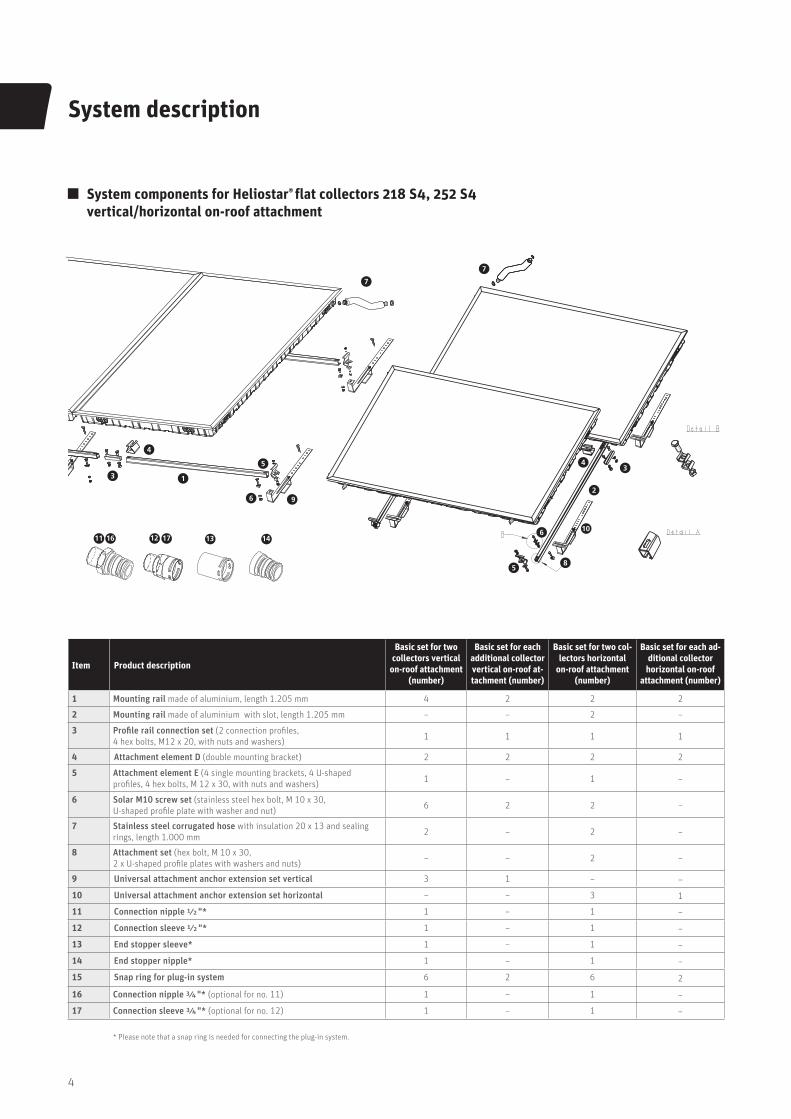
1 Mounting rail made of aluminium, length 1.205 mm 4 2 2 2
2 Mounting rail made of aluminium with slot, length 1.205 mm – – 2 –
3 Profile rail connection set (2 connection profiles,
4 hex bolts, M12 x 20, with nuts and washers)1 1 1 1
4 Attachment element D (double mounting bracket) 2 2 2 2
5 Attachment element E (4 single mounting brackets, 4 U-shaped
profiles, 4 hex bolts, M 12 x 30, with nuts and washers)1 – 1 –
6 Solar M10 screw set (stainless steel hex bolt, M 10 x 30,
U-shaped profile plate with washer and nut)6 2 2 –
7 Stainless steel corrugated hose with insulation 20 x 13 and sealing
rings, length 1.000 mm2 – 2 –
8 Attachment set (hex bolt, M 10 x 30,
2 x U-shaped profile plates with washers and nuts)– – 2 –
9 Universal attachment anchor extension set vertical 3 1 – –
10 Universal attachment anchor extension set horizontal – – 3 1
11 Connection nipple ½ "* 1 – 1 –
12 Connection sleeve ½ "* 1 – 1 –
13 End stopper sleeve* 1 – 1 –
14 End stopper nipple* 1 – 1 –
15 Snap ring for plug-in system 6 2 6 2
16 Connection nipple ¾ "* (optional for no. 11) 1 – 1 –
17 Connection sleeve ¾ "* (optional for no. 12) 1 – 1 –
* Please note that a snap ring is needed for connecting the plug-in system.
System components for Heliostar® flat collectors 218 S4, 252 S4
vertical/horizontal on-roof attachment
7
7
34
2
5
10
96
1
4
3
5
8
611 12 13 1416 17
5
System description
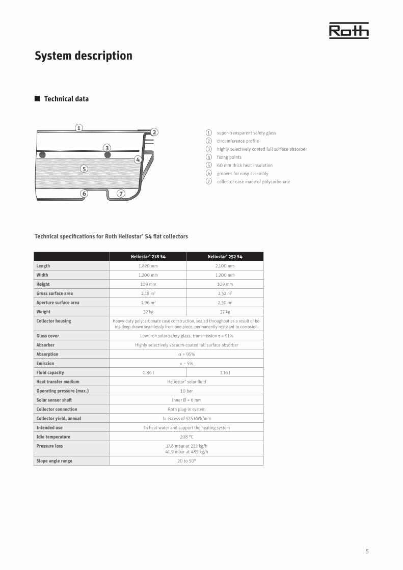
Technical data
1 super-transparent safety glass
2 circumference profile
3 highly selectively coated full surface absorber
4 fixing points
5 60 mm thick heat insulation
6 grooves for easy assembly
7 collector case made of polycarbonate
Heliostar® 218 S4 Heliostar® 252 S4
Length 1.820 mm 2.100 mm
Width 1.200 mm 1.200 mm
Height 109 mm 109 mm
Gross surface area 2,18 m2 2,52 m2
Aperture surface area 1,96 m2 2,30 m2
Weight 32 kg 37 kg
Collector housing Heavy-duty polycarbonate case construction, sealed throughout as a result of be-
ing deep drawn seamlessly from one piece, permanently resistant to corrosion.
Glass cover Low-iron solar safety glass, transmission = 91%
Absorber Highly selectively vacuum-coated full surface absorber
Absorption = 95%
Emission = 5%
Fluid capacity 0,86 l 1,16 l
Heat transfer medium Heliostar® solar fluid
Operating pressure (max.) 10 bar
Solar sensor shaft Inner Ø = 6 mm
Collector connection Roth plug-in system
Collector yield, annual In excess of 525 kWh/m2a
Intended use To heat water and support the heating system
Idle temperature 208 °C
Pressure loss 17,8 mbar at 233 kg/h
41,9 mbar at 485 kg/h
Slope angle range 20 to 50°
12
4
3
5
6 7
Technical specifications for Roth Heliostar® S4 flat collectors
6
Installation requirements
Safety Instructions
Please read these assembly instructions carefully prior to
installation and ensure adherence to all the safety instructions
given here. Always ensure adherence to all relevant Work Safety
regulations and that all technology is state-of-the-art, in particu-
lar where relevant to roof work.
Important: If collectors are stored prior to assembly, always
ensure that they are never stored in the open air, lying on their
glass surface and/or uncovered, as otherwise this may allow
moisture to penetrate the vent holes in the frame. The collectors
must only be stored on a level surface and the housing protected
against external forces! To avoid the risk of scalding, the system
should not be filled in bright sunlight! If there is a risk of frost,
always make sure there is sufficient antifreeze available when
filling and rinsing the system.
Work Safety regulations,
state-of-the-art technology
> Roof installations: DIN 18338
Roof covering and roof sealing works,
DIN 18339 Sheet-metal works,
DIN 18451 Scaffolding works
> Connecting thermal solar systems:
DIN 4757 Parts 1 and 3
> Electrical connection: VDE 0100 Setting up
electrical equipment, VDE 0185
general information for erecting
lightning protection systems, VDE 0190
main equipotential bonding of electrical systems,
DIN 18382 electrical cable and wiring system in buildings
The professional builders associations provide detailed
information on accident prevention regulations!
Proper use of ladders
Ladders should only be used for a working height below 5 m.
Position the ladder at an angle of 65° to 75° and secure. The top
end of the ladder must extend at least 1 m above exit point.
Fall protection devices
If working at a height above 3 m, always use fall protection
equipment when working on sloping roofs (20° to 60°) (VBG 37,
§8). The vertical distance for a workplace fall-protection device
(roof fall-prevention device or alternative protective roof barrier)
is max. 5 m. A safety harness may also be used as fall protection.
Secure universal attachment safety anchors to load-bearing parts
above the worker. Do not use ladder hooks!
Protection against falling objects
Access routes and workplaces located below the work site must be
protected against falling or toppling objects. These areas must be
clearly signed and cordoned off.
Information is also available via the
Roth hotline: +49 (0)6466/922-266
7
Installation requirements
Assembly Instructions
General requirements
The on-roof attachment set is suitable for installing Roth
Heliostar® flat collectors on roofs with a slope angle of 22° or
more. Universal fastening anchor versions are available for roofs
covered with roof pantiles and similar roof tiles, as well as
plain tiles and fibre cement corrugated sheets. On natural slate
roofs, you should only have work carried out by a professional
roofing firm.
Equipotential bonding and lightning protection
The metal pipes of the solar circuit must be connected to the
main equipotential busbar by a green and yellow conductor of
at least 16 mm2 Cu (H07 V- or R). The collectors can be included
in an existing lightning protection system if one is available.
Alternatively, they can be earthed via an earth rod.
The earth wire must be run down the outside of the house.
The earth must also be connected to the main equipotential
busbar by a wire of the same cross-section.
Fitting the sensor
The sensor must be fitted in the last collector with fluid flowing
through it on the side of the forward flow to the storage tank
(hot outlet). To do this, remove the rubber sleeve and thread the
sensor through, pushing the mineral wool inside the collector
slightly to one side. Then apply a little heat conductive paste to
the sensor and insert it in the immersion sleeve as far as it will go.
Finally push the rubber sleeve back on again until the ridge
catches on the collector frame. If you need to extend the sensor
wire, you can use a wire cross-section of 2 x 0,75 mm up to a
length of 50 m. For a longer length, you need to select a cross-
section of 2 x 1,5 mm. To protect the connected controller from
power surges, the collector sensor must be appropriately extended
via a surge plug (optional extra) directly behind the collector.
List of tools
> Spanner 13/17/19/20/22
> Drilling machine, star drill bit PZ 3
> Angle grinder with stone cutting disc
> Hammer
> String (approx. 10 m), tape measure and rope
> Pencil
Statics
Check that the roof construction is appropriate for the solar
system before installing it. In addition, sheet metal roof tiles or
metal plates must be used as the substructure for the universal
attachment anchors! Taking account of the relevant local
conditions, such as snow load, wind load, building height and roof
substructure, it is the responsibility of the planner and/or
the building owner to secure the solar system by increasing the
number of attachment anchors if necessary (see also instructions
for increased snow loads). The manufacturer can accept no
liability in this regard! We would be pleased to advise you!
8
Installation requirements
Assembly Instructions
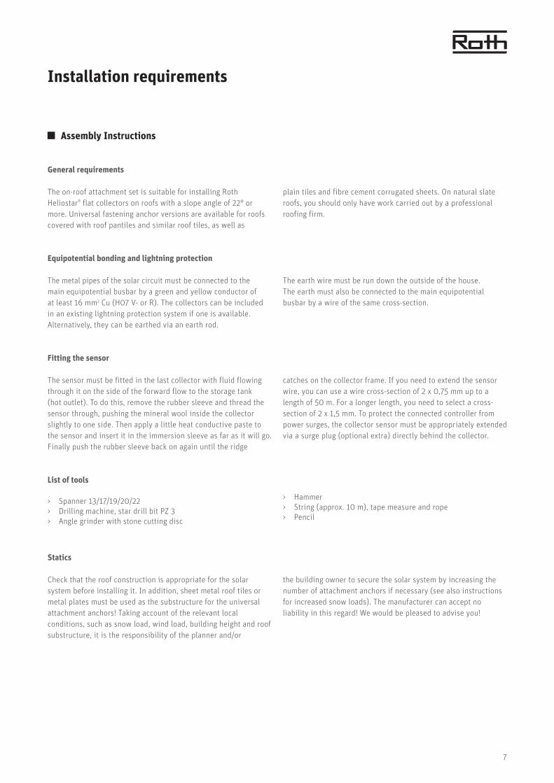
Instructions for increased snow loads
Maximum snow load for an installation with a collector slope of
30 to 40° for Heliostar® 252 S4 and 218 S4
SLZ = snow load zone
When calculating the applicable snow load zones, you must take
into account the map in accordance with DIN 1055-5.
A shape coefficient of 0,8 in accordance with DIN 1055-5 is used
for the calculation, which corresponds to a roof slope of 30°.
Universal attachment anchor
Snow heights m AMSL
Special rafter anchor
Snow heights m AMSL.
SLZ 1 1.056/1.048 1.539/1.660
SLZ 1a 909/1.003 1.363/1.465
SLZ 2 682/731 1.011/1.096
SLZ 2 a 571/639 882/958
SLZ 3 521/557 786/859
Max.
surface load1,9/2,2 kN/m2 3,65/4,21 kN/m2
9
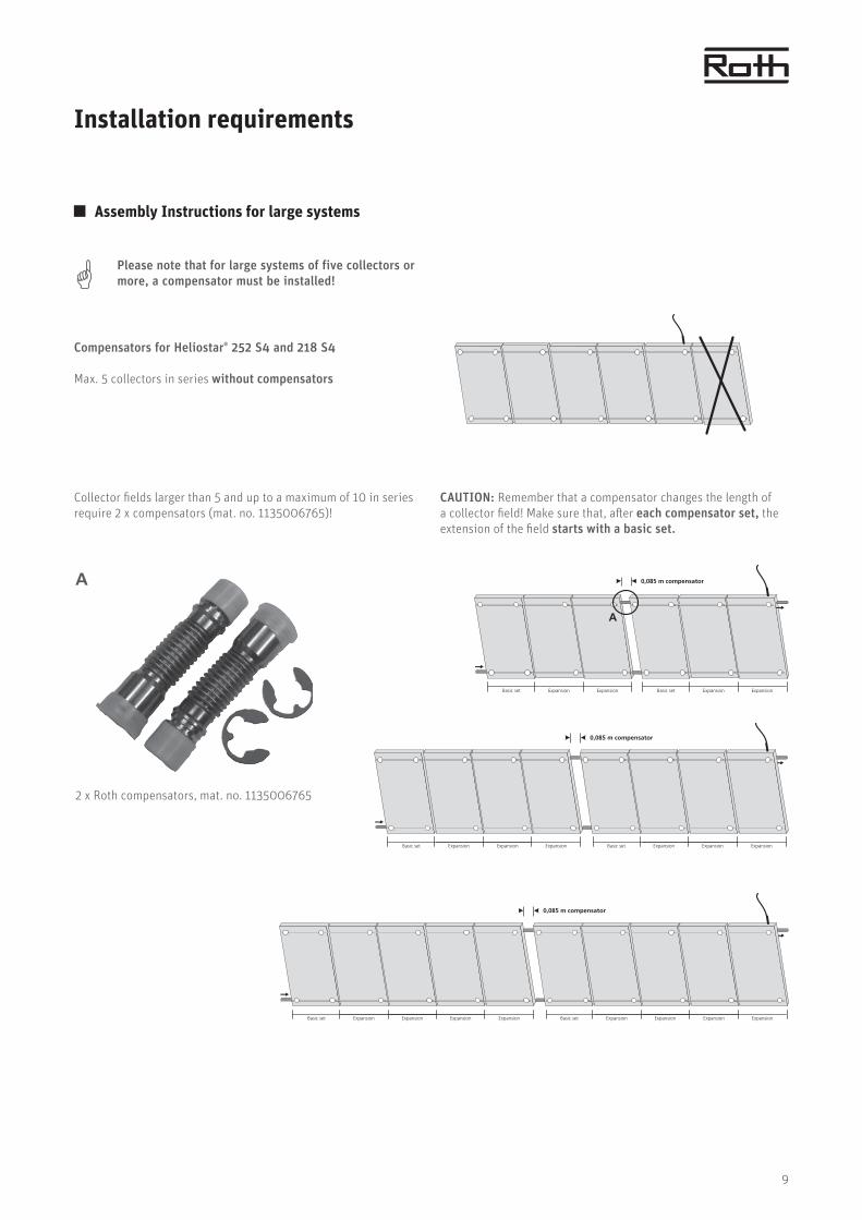
2 x Roth compensators, mat. no. 1135006765
A
Please note that for large systems of five collectors or
more, a compensator must be installed!
Basic set Expansion Expansion Expansion Expansion Basic set
0,085 m compensator
Expansion Expansion Expansion Expansion
Installation requirements
Assembly Instructions for large systems
Compensators for Heliostar® 252 S4 and 218 S4
Max. 5 collectors in series without compensators
Collector fields larger than 5 and up to a maximum of 10 in series
require 2 x compensators (mat. no. 1135006765)!
CAUTION: Remember that a compensator changes the length of
a collector field! Make sure that, after each compensator set, the
extension of the field starts with a basic set.
Basic set Expansion Expansion Basic set
0,085 m compensator
A
Expansion Expansion
Basic set Expansion Expansion Expansion Basic set
0,085 m compensator
Expansion Expansion Expansion

10
Installation requirements
Heliostar® 252 S4 system versions
Collector area: 2,52 m2
0,8 m 0,8 m
1,20 m 2,40 m
1-1,2 m
4,80 m
0,8 m 1-1,2 m 1-1,2 m 1-1,2 m
6,00 m
0,8 m 1-1,2 m 1-1,2 m 1-1,2 m 1-1,2 m
0,8 m 1-1,2 m 1-1,2 m
2,10
m
2,10
m
2,10
m
2,10
m
2,10
m
1,64
m
1,64
m
1,64
m
1,64
m
1,64
m
3,60 m
For collector fields >5 collectors, please follow the assembly instruction on page 9.
1,20
m
2,40
m
6,00
m
4,80
m
3,60
m
1,64 m
1,64 m
1,64 m
1,64 m
1,64 m
0,8–
1,0
m
1,0–
1,2
m
0.8–
1,0
m
1.0–
1,2
m1.
0–1,
2 m
0.8–
1,0
m
For collector fields >5 collectors, please follow the assembly instruction on page 9.
Vertical collector installation
Horizontal collector installation
11
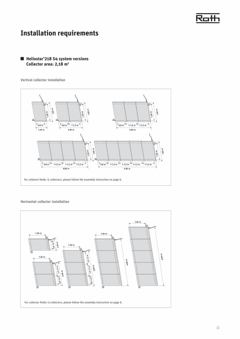
Installation requirements
Heliostar®218 S4 system versions
Collector area: 2,18 m2
Vertical collector installation
Horizontal collector installation
0,8 m 0,8 m
1,20 m 2,40 m
1-1,2 m
4,80 m
0,8 m 1-1,2 m 1-1,2 m 1-1,2 m
6,00 m
0,8 m 1-1,2 m 1-1,2 m 1-1,2 m 1-1,2 m
0,8 m 1-1,2 m 1-1,2 m
1,82
m
1,82
m
1,82
m
1,82
m
1,82
m
1,36
m
1,36
m
1,36
m
1,36
m
1,36
m
3,60 m
For collector fields >5 collectors, please follow the assembly instruction on page 9.
1,20
m
2,40
m
6,00
m
4,80
m
3,60
m
1,36 m
1,36 m
1,36 m
1,36 m
1,36 m
0,8–
1,0
m
1,0–
1,2
m
0,8–
1,0
m
1,0–
1,2
m1,
0–1,
2 m
0,8–
1,0
m
For collector fields >5 collectors, please follow the assembly instruction on page 9.
12
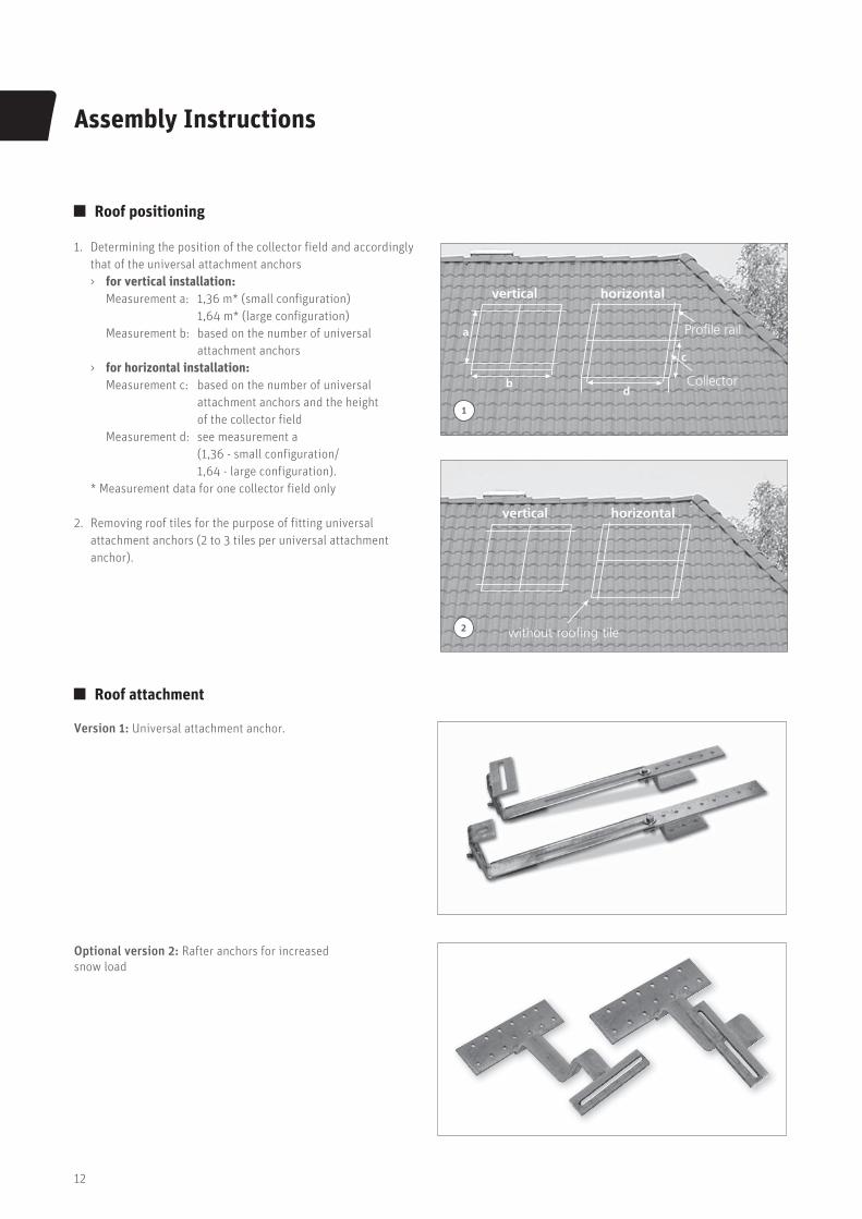
Assembly Instructions
Roof positioning
1. Determining the position of the collector field and accordingly
that of the universal attachment anchors
> for vertical installation:
Measurement a: 1,36 m* (small configuration)
1,64 m* (large configuration)
Measurement b: based on the number of universal
attachment anchors
> for horizontal installation:
Measurement c: based on the number of universal
attachment anchors and the height
of the collector field
Measurement d: see measurement a
(1,36 - small configuration/
1,64 - large configuration).
* Measurement data for one collector field only
2. Removing roof tiles for the purpose of fitting universal
attachment anchors (2 to 3 tiles per universal attachment
anchor).
vertical horizontal
Profile rail
Collector
a
b
c
d
1
vertical horizontal
without roofing tile2
Roof attachment
Version 1: Universal attachment anchor.
Optional version 2: Rafter anchors for increased
snow load

13
Assembly Instructions
3
3. For your safety: Fall arresters must be worn for all tasks where
there is a risk of falling (see page 6).
4. Do not step onto the mounting rail.
4
Fitting rafter anchors for increased snow load
Fasten rafter anchors to roof batten using 3 screws, 6 x 80, each.
Roof hook must sit in the recess above the tiles.
Important:
The roof hook must not exert any pressure on the roof tiles!
continue with assembly steps, point 1
Safety Instruction
Substructure universal attachment anchor and optional rafter anchor for increased snow load

14
Assembly Instructions
Substructure universal attachment anchor and optional rafter anchor for increased snow load
Assembly steps with universal attachment anchor
Sheet metal tiles are strongly recommended for use as the
substructure!
Fasten universal attachment anchor to roof batten using 3 screws,
6 x 80. Universal attachment anchor must sit in the recess above
the tiles.
Important:
The universal attachment anchor must not exert any pressure on
the roof tiles!
Placement of sheet metal tiles
Set screw to vary the rafter anchor spacing
Not required for slate and plain tile covering

15
Assembly Instructions
1. Preassemble profile rails on the ground.
Important:
The screws for the connection between profile rail and universal
attachment anchor must be inserted before the individual profile
segments are joined. To do this, measure the positions of the
universal attachment anchors and mark them on the profile rails.
Insert a screw with U-shaped profile plate there in each case.
2./3. After this, insert the connector into the side of the profile
rails.
4. When connecting the two profile rails, push the mounting
bracket into the notch provided on the front side of the profile
rails (with horizontal assembly, ensure that the profile rail with
a closed slot is used as the lower rail – see detail A, page 4).
1
Assembly steps
2
3
4
16
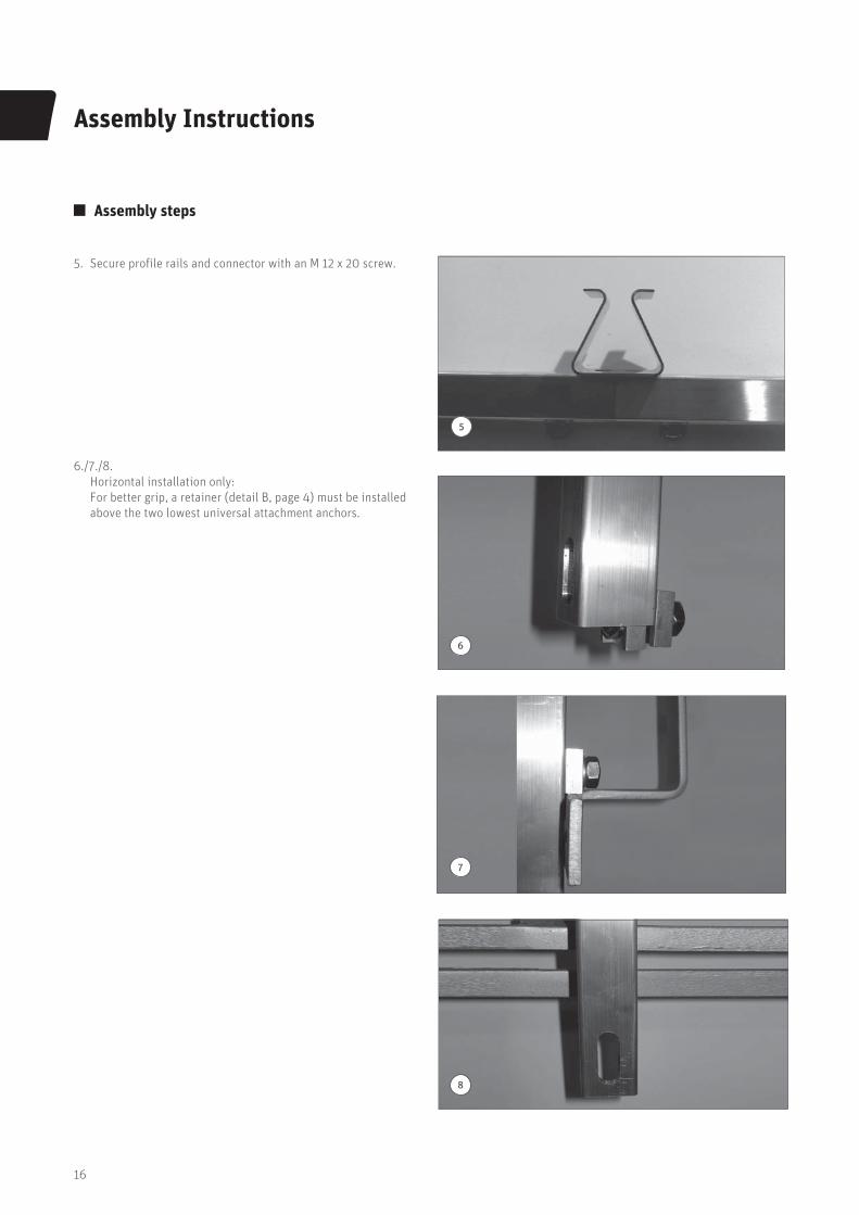
Assembly Instructions
Assembly steps
5. Secure profile rails and connector with an M 12 x 20 screw.
6./7./8.
Horizontal installation only:
For better grip, a retainer (detail B, page 4) must be installed
above the two lowest universal attachment anchors.
5
6
7
8

17
Assembly Instructions
Assembly steps
9./10. Screw on the profile rails with M 10 x 30 hex bolts and
screw on the U-shaped profile plates through the slots
in the universal attachment anchors.
11. Use uniform measurement A to ensure that the profiles are
parallel (see page 12). Use a piece of string to check the
diagonals of the profile rails and readjust differences in length
if necessary. If measurement is C = B, the profile rails are
flush and can be screwed in place. Ensure that measurement A
does not change again during readjustment. If necessary, you
should mark the position of the rail on the universal attachment
anchor for this purpose.
12. There are slots located on the rear of the collector (for vertical
and horizontal installation) to fit the collector onto the profile
rails.
B
9
10
AC
A
Profile rail 2
Profile rail 1
11
12
18
Assembly Instructions
Assembly steps
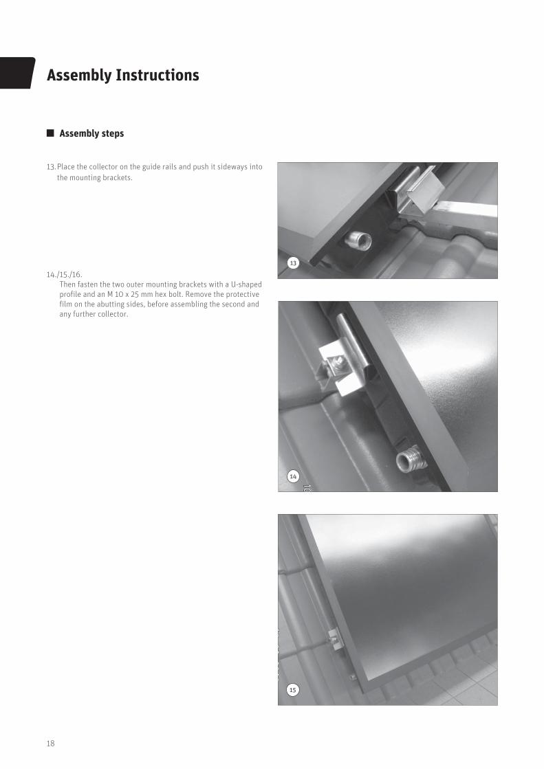
13. Place the collector on the guide rails and push it sideways into
the mounting brackets.
14./15./16.
Then fasten the two outer mounting brackets with a U-shaped
profile and an M 10 x 25 mm hex bolt. Remove the protective
film on the abutting sides, before assembling the second and
any further collector.
13
14
15
19
Assembly Instructions
Assembly steps
16
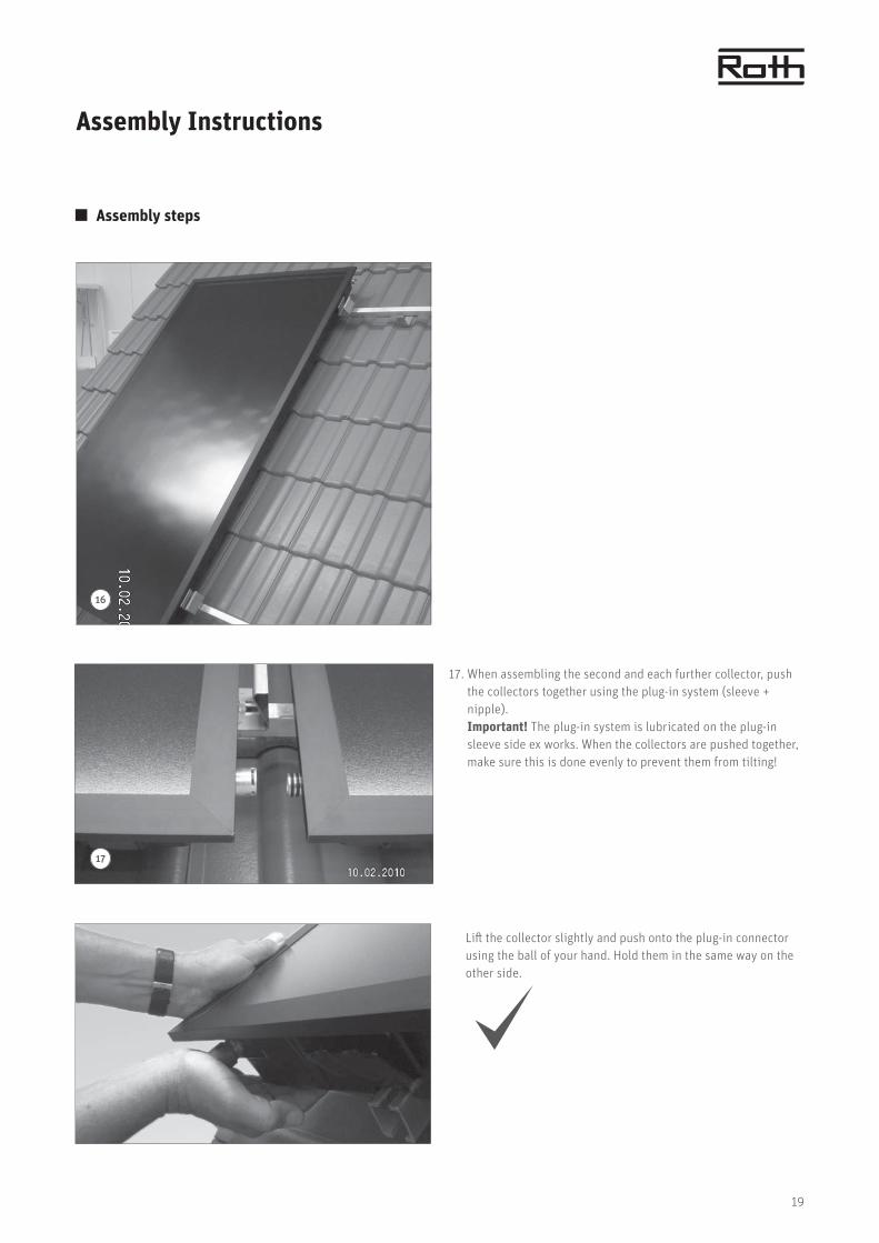
17. When assembling the second and each further collector, push
the collectors together using the plug-in system (sleeve +
nipple).
Important! The plug-in system is lubricated on the plug-in
sleeve side ex works. When the collectors are pushed together,
make sure this is done evenly to prevent them from tilting!
Lift the collector slightly and push onto the plug-in connector
using the ball of your hand. Hold them in the same way on the
other side.
17
20
Assembly Instructions
Assembly steps
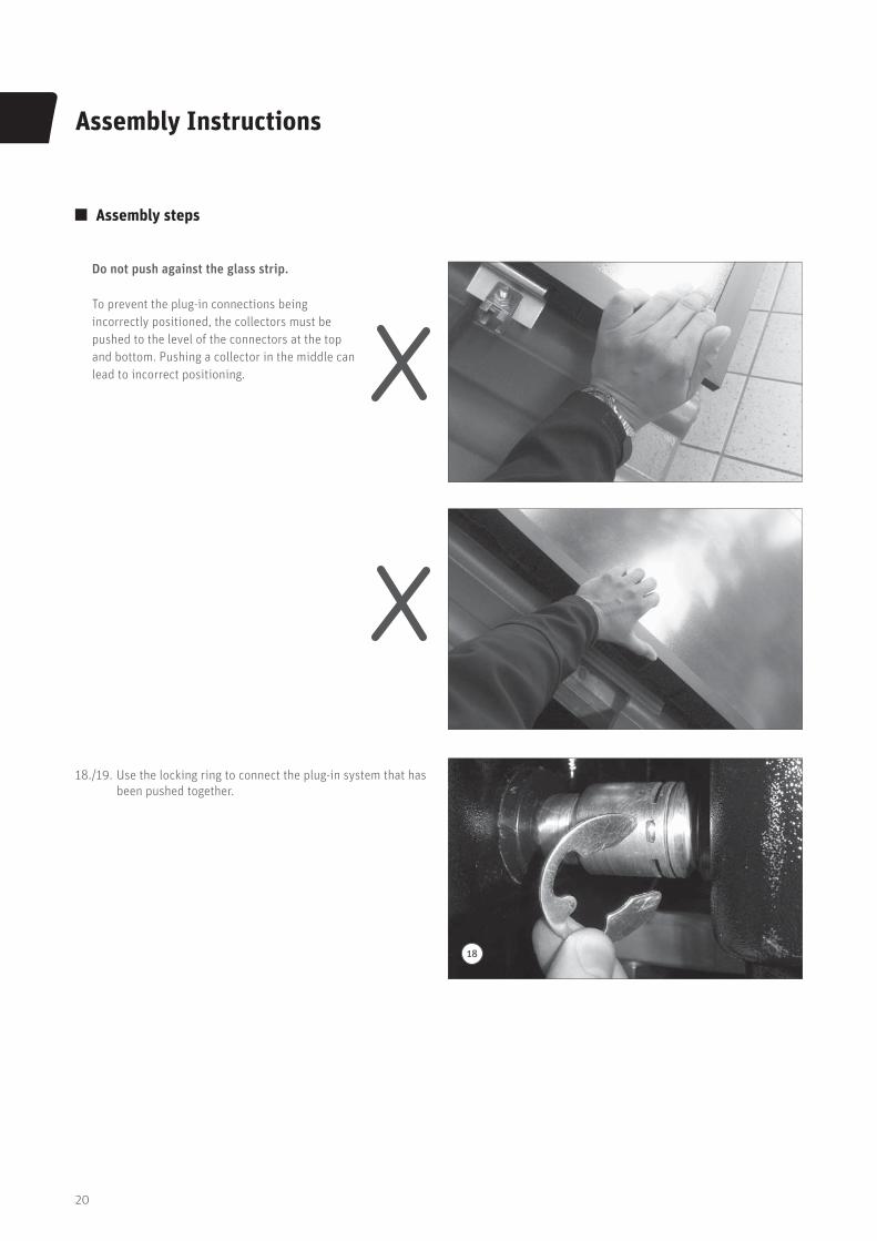
Do not push against the glass strip.
To prevent the plug-in connections being
incorrectly positioned, the collectors must be
pushed to the level of the connectors at the top
and bottom. Pushing a collector in the middle can
lead to incorrect positioning.
18./19. Use the locking ring to connect the plug-in system that has
been pushed together.
18
21
Assembly Instructions
Assembly steps
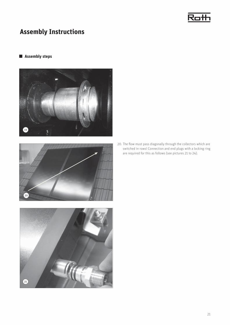
20. The flow must pass diagonally through the collectors which are
switched in rows! Connection and end plugs with a locking ring
are required for this as follows (see pictures 21 to 24).
19
20
21

22
Assembly Instructions
Assembly steps
25. When mounting the corrugated hose couplings, ensure that the
flat packing is correctly seated. Always apply counter pressure
when tightening the threaded connections on the collector.
Failure to do so may cause irreparable damage to the collector.
22
23
24
25

23
Assembly Instructions
Assembly steps
26. To fit the sensor, remove the rubber sleeve on the short upper
side of the collector, thread the sensor through, apply heat
conductive paste and push it into the immersion sleeve as far
as it will go. Then push in the rubber sleeve as far as the back
of the ridge.
27. Prepare ventilation tile (cut open grid) and, if necessary,
remove any existing sarking felt underlay and attach in the
raised position or use adhesive couplers (from specialist
outlet). Take care that the corrugated hose is installed in
ascending position!
26
27
28
24
Installation requirements
Maintenance Instructions
Intended use to heat water and support the heating system
In order for the thermal solar system to work without any
technical problems, it should be maintained regularly
(ideally as part of the annual heating maintenance).
This should include:
> Visual inspection of the collectors and pipe insulation
> Examination of electrical connections
> Examination of switching functions and flow rate
> Examination of the anti-freeze

25
Equipment operator
Surname ___________________________________________
First name ___________________________________________
Street ___________________________________________
Postcode, city ___________________________________________
Telephone ___________________________________________
Commissioning date: ________________________________
Check list and commissioning log
for thermal solar systems
Installation company
Company ___________________________________________
Installed by ___________________________________________
Street ___________________________________________
Postcode, city ___________________________________________
Telephone ___________________________________________
Collectors
Manufactured by ________________________________________
Serial number ________________________________________
________________________________________
Direction
Quantity ___________________________
Gross surface
area, total ___________________________
Circuitry
Use of the solar heating equipment
Preparation of domestic water
Domestic water with heating support
Other
Control system
Roth BW control system
Roth BW/H control system
Roth HE efficiency control system
Roth BW/H-HE efficiency control system
Roth BW/H Comfort HE efficiency control system
Solar station
RS 25/6
RS 25/7
UPS 25/12
ST 25/7 PWM
Expansion tank ________ litres
System pressure ________ bar
Volume flow ________ litres per minute
yes no
System properly flushed and aired
Anti-freeze content tested (recomm.: 40%)
Sensor correctly positioned
Controller functionality check
N
S
W E
Storage tank
Type ___________________________________ Size ___________________________
Quantity ___________________________
Equipment operator's signature Installer's signature
26
Guarantee
GUARANTEE DOCUMENTRoth Solar Systems
Heliostar® at olle tors
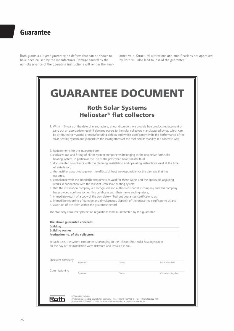
1. Within 10 years of the date of manufacture, at our discretion, we provide free product replacement or carry out an appropriate repair if damage occurs to the solar collectors manufactured by us, which can be attributed to material or manufacturing defects and which signi cantly limits the performance of the solar heating system and jeopardises the leaktightness of the roof and its stability in a concrete way.
ROTH WERKE GMBHAm Seerain 2 35232 Dautphetal, Germany Tel. +49 (0) 6466/922-0 Fax +49 (0)6466/922-100Hotline +49 (0)6466/922-266 Email [email protected] www.roth-werke.de
Specialist company Signature Stamp Installation date
Commissioning Signature Stamp Commissioning date
2. Requirements for this guarantee are:a. exclusive use and tting of all the system components belonging to the respective Roth solar
heating system, in particular the use of the prescribed heat transfer uid,b. documented compliance with the planning, installation and operating instructions valid at the time
of installation,c. that neither glass breakage nor the effects of frost are responsible for the damage that has
occurred,d. compliance with the standards and directives valid for these works and the applicable adjoining
works in connection with the relevant Roth solar heating system,e. that the installation company is a recognised and authorised specialist company and this company
has provided con rmation on this certi cate with their name and signature,f. immediate return of a copy of the completely lled out guarantee certi cate to us,g. immediate reporting of damage and simultaneous dispatch of the guarantee certi cate to us andh. assertion of the claim within the guarantee period.
The statutory consumer protection regulations remain unaffected by this guarantee.
The above guarantee concerns:BuildingBuilding ownerProduction no. of the collectors:
In each case, the system components belonging to the relevant Roth solar heating system on the day of the installation were delivered and installed in full.
Roth grants a 10-year guarantee on defects that can be shown to
have been caused by the manufacturer. Damage caused by the
non-observance of the operating instructions will render the guar-
antee void. Structural alterations and modifications not approved
by Roth will also lead to loss of the guarantee!

27
Notes
Generation
> Solar systems> Heat pump systems> Solar heat pump systems
Storage
Storage systems for > Domestic and heating water> Combustibles and biofuels> Rainwater and waste water
Application
> Radiant heating and cooling systems
> Pipe installation systems> Shower systems
Roth Energy and Sanitary Systems
ROTH WERKE GMBH
Am Seerain 2
35232 Dautphetal, Germany
Telefon: +49 6466/922-0
Telefax: +49 6466/922-100
Hotline: +49 6466/922-266
E-Mail: [email protected]
www.roth-werke.de
Mat
eria
l No.
: 115
00
1058
0
Subj
ect t
o te
chni
cal m
odifi
cati
ons.


![z] 1 /s4 y, ke · 2017. 11. 13. · z] 1 /s4 y, ke. z] 1 /s4 y, ke. z] 1 /s4 y, ke](https://static.fdocuments.us/doc/165x107/60f90cb7bf544418fc224166/-z-1-s4-y-ke-2017-11-13-z-1-s4-y-ke-z-1-s4-y-ke-z-1-s4-y-ke.jpg)