Energy Systems Engineering Technology - isu.edu · Energy Systems Engineering Technology Electrical...
22
Energy Systems Engineering Technology Electrical Safety Module Page 1 College of Technology Motors and Controls Module # 1 Electrical Safety Document Intent: The intent of this document is to provide an example of how a subject matter expert might teach Electrical Safety. This approach is what Idaho State University College of Technology is using to teach its Energy Systems Instrumentation and Control curriculum for electrical safety. The approach is based on a Systematic Approach to Training where training is developed and delivered in a two step process. This document depicts the two step approach with knowledge objectives being presented first followed by skill objectives. Step one teaches essential knowledge objectives to prepare students for the application of that knowledge. Step two is to let students apply what they have learned with actual hands on experiences in a controlled laboratory setting. Examples used are equivalent to equipment and resources available to instructional staff members at Idaho State University. Fundamentals of Electrical Safety Introduction: This module covers fundamental aspects of electrical safety as essential knowledge necessary to perform work safely according to national and local standards on or around electrical power sources that are associated with motors and controls. Students will be taught the fundamentals of electrical safety using classroom instruction, demonstration, and laboratory exercises to demonstrate knowledge and skill mastery of electrical safety. Completion of this module will allow students to demonstrate mastery of knowledge and skill objectives by completing a series of tasks demonstrating safe work practices on or around electrical power sources.
Transcript of Energy Systems Engineering Technology - isu.edu · Energy Systems Engineering Technology Electrical...

Energy Systems Engineering Technology
Electrical Safety Module Page 1
College of Technology
Motors and Controls
Module # 1 Electrical Safety
Document Intent:
The intent of this document is to provide an example of how a subject matter expert might teach
Electrical Safety. This approach is what Idaho State University College of Technology is using
to teach its Energy Systems Instrumentation and Control curriculum for electrical safety. The
approach is based on a Systematic Approach to Training where training is developed and
delivered in a two step process. This document depicts the two step approach with knowledge
objectives being presented first followed by skill objectives. Step one teaches essential
knowledge objectives to prepare students for the application of that knowledge. Step two is to
let students apply what they have learned with actual hands on experiences in a controlled
laboratory setting.
Examples used are equivalent to equipment and resources available to instructional staff
members at Idaho State University.
Fundamentals of Electrical Safety Introduction:
This module covers fundamental aspects of electrical safety as essential knowledge necessary to
perform work safely according to national and local standards on or around electrical power
sources that are associated with motors and controls. Students will be taught the fundamentals of
electrical safety using classroom instruction, demonstration, and laboratory exercises to
demonstrate knowledge and skill mastery of electrical safety. Completion of this module will
allow students to demonstrate mastery of knowledge and skill objectives by completing a series
of tasks demonstrating safe work practices on or around electrical power sources.

Energy Systems Engineering Technology
Electrical Safety Module Page 2
References
This document includes knowledge and skill sections with objectives, information, and examples
of how process control could be taught in a vocational or industry setting. This document has
been developed by Idaho State University’s College of Technology. Reference material used
includes information from:
American Technical Publication – Electrical Motor Controls for Integrated Systems, Third
Edition, by Gary J. Rockis and Glen A. Mazur, ISBN 0-8269-1207-9
Department of Energy Fundamentals Handbook, Electrical Safety, DOE-HDBK-1092-
2004, December 2004 (Superseding DOE-HDBK-1092-98), http://tis.eh.doe.gov/techstds/
Re-Distributed by http://www.tpub.com
Current National Electrical Code, NFPA

Energy Systems Engineering Technology
Electrical Safety Module Page 3
STEP ONE
Electrical Safety Course Knowledge Objectives
Knowledge Terminal Objective (KTO)
KTO 1.1. EVALUATE all aspects of ELECTRICAL SAFETY to ensure selection of tools,
equipment, and safety requirements (to include Standards, Policies, and Procedures)
are known and utilized in all aspects of work with or around electrical equipment and
systems associated with general electrical circuits and Motor Controls.
Knowledge Enabling Objectives (KEO)
KEO 1. 1. DESCRIBE how ELECTRICAL SAFETY has been advanced by the efforts
of other organizations.
KEO 1. 2. DESCRIBE what the NFPA is, what it sponsors, and worker responsibilities
that apply to you when working on or around motor control circuits.
KEO 1. 3. DESCRIBE what the NEC is and general safety rules it specifies for electrical
workers.
KEO 1. 4. EXPLAIN what NFPA 70E PART II addresses.
KEO 1. 5. EXPLAIN what SAFETY LABELS are to include: Danger Signal Word,
Warning Signal Word, Caution Signal Word, Electrical Signal Word, and
Explosion Warning Signal Word.
KEO 1. 6. DESCRIBE what the NEC Article 430 is.
KEO 1. 7. EXPLAIN what ELECTRICAL SHOCK is and how you can reduce or
prevent an Electrical Shock.

Energy Systems Engineering Technology
Electrical Safety Module Page 4
KEO 1. 8. EXPLAIN the difference between a GROUNDED and GROUNDING
CONDUCTORS
KEO 1. 9. DESCRIBE what GROUNDING is and how it is accomplished.
KEO 1. 10. DESCRIBE what a GFCI is and how it protects against a shock hazard.
KEO 1. 11. EXPLAIN the difference between a HOT and a NEUTRAL CONDUCTOR
how a person could receive a shock from a neutral conductor.
KEO 1. 12. DESCRIBE what the IEC is and how it applies to electrical workers.
KEO 1. 13. DESCRIBE what PPE is and how NFPA and OSHA regulate PPE.
KEO 1. 14. EXPLAIN what LOCKOUT/TAGOUT is and how it is accomplished.
KEO 1. 15. EXPLAIN what FIRE SAFETY is to include: Classes of Fire, In-Plant
Training, and Hazardous Locations.
KEO 1. 16. EXPLAIN what a CONFINED SPACE is to include: Confined Space
Permits, and Entry Permit Procedures.
KEO 1. 17. EXPLAIN PRECAUTIONS for work around OVERHEAD or UNDER
GROUND POWER LINES.

Energy Systems Engineering Technology
Electrical Safety Module Page 5
FUNDAMENTALS OF ELECTRICAL SAFETY
KEO 1. 1. DESCRIBE how ELECTRICAL SAFETY has been advanced by the efforts
of other organizations.
ELECTRICAL SAFETY has been advanced by the efforts of the National Fire Prevention
Association (NFPA), Occupational Safety and Health Administration (OSHA), and
individual Local State and City Governments.
National Fire Prevention Association (NFPA) is a National Organization that
provides guidance in the assessment of hazards and the products of combustion.
The 2009 NFPA 70E®: Standard for Electrical Safety in the Workplace® is the solution to
jobsite protection from electrical hazards.
Shock, electrocution, arc flash, and arc blast are responsible for one fatality every workday in
the U.S., and some 8,000 workers are treated in emergency rooms for electrical contact
injuries each year. Now NFPA 70E--the Standard developed for OSHA--is revised to address
safety gaps and increase electrical worker protection, while helping companies comply with
OSHA 1910 Subpart S and OSHA 1926 Subpart K. Major changes recognize new hazards
and address safety gaps.
Personal Protective Equipment (PPE) protects personnel and can significantly reduce the
risk of injury in an arc flash. To help electrical engineers calculate incident energy--the vital
first step in determining the correct type of PPE for a given task--revised Annex D
consolidates all equations, adds new tables, and offers more options to detailed calculations.
Workers, Supervisors and Managers, Contractors, Risk Managers, Engineers, and Job
Planners, all have a stake in ending electrical-related accidents, liability, and loss. Through
awareness and hazard analysis, they all rely on the 2009 NFPA 70E to improve worker safety
as a solution to jobsite protection from electrical hazards.
Occupational Safety and Health Administration (OSHA) is an agency of the United
States Department of Labor. It was created by Congress of the United States under
the Occupational Safety and Health Act, signed by President Richard M. Nixon, on
December 30, 1970. Its mission is to prevent work-related injuries, illnesses, and
occupational fatality by issuing and enforcing standards for workplace safety and
health. The agency is headed by a Deputy Assistant Secretary of Labor, of the United
States who is a member of the cabinet of the President of the United States

Energy Systems Engineering Technology
Electrical Safety Module Page 6
OSHA's MISSION:
With the Occupational Safety and Health Act of 1970, Congress created the
Occupational Safety and Health Administration (OSHA) to ensure safe and
healthful working conditions for working men and women by setting and
enforcing standards and by providing training, outreach, education and assistance.
ORGANIZATION:
OSHA is part of the United States Department of Labor. The administrator for
OSHA is the Assistant Secretary of Labor for Occupational Safety and Health.
OSHA's administrator answers to the Secretary of Labor.
OSHA COVERAGE:
The OSH Act covers employers and their employees either directly through
federal OSHA or through an OSHA-approved state program. State programs must
meet or exceed federal OSHA standards for workplace safety and health.
Local State and City Governments provide oversight and enforcement of both NFPA
70E (Standard for Electrical Safety in the Workplace) and OSHA 1910.132-138
(dealing with Personal Protective Equipment). This is accomplished by Inspectors at
State and City levels to enforce requirements of safety and protection of personnel
and property. Many State, City, and Counties provide additional Electrical Codes
specific to their local areas. These codes are in support of all National Electrical
Code requirements and will either meet or exceed the NEC® code requirements. It is
the responsibility of workers to ensure they are aware of any additional code
requirements besides the NEC® to work to.
KEO 1. 2. DESCRIBE what the NFPA is, what it sponsors, and worker responsibilities
that apply to you when working on or around motor control circuits.
NFPA is a National Organization that provides guidance in the assessment of hazards. It
sponsors the Development of the National Electrical Code® (NEC®). It is the responsibility
of all workers to understand the Regulations and Requirements associated with NFPA when
they work on or around motor control circuits.
More importantly, it is the responsibility for employers to ensure workers understand these
Regulations and Requirement through not only enforcement, but by providing training and
workplace assessments to ensure workers are protected and working safely. Employers also
need to perform hazard assessments of work areas prior to work commencing and during the
performance of work activities. Workers are also expected to know how to analyze hazards

Energy Systems Engineering Technology
Electrical Safety Module Page 7
and can stop work if they feel something is not right. This right to stop work is provided to
any worker or ever an individual in the work area that sees something they perceive as an
unsafe environment of an unsafe work practice being performed.
IMPORTANT NOTE:
Workers should not assume that who they are working for have mitigated all safety
hazards and must at all times use their technical knowledge to ensure that hazards
have been identified and mitigated. If they have not, they must stop work and report
any unsafe condition or event. In other words, Workers are as much, if not more
responsible for their own safety than for employers they are working for.
The NFPA along with the NEC addresses voltage levels. The NFPA and NEC do not
officially define the voltages as Low, Medium, or High Voltage. However industry
standards look at what the NEC and NFPA requirements and have determined the following:
Low Voltage is considered to be less than 50 Volts
Medium Voltage is considered to be between 50 to 600 Volts
High Voltage is considered to be anything above 600 Volts
For example, the NEC and NFPA both address the fact that 50 Volts or less are not factored
into NEC requirements and NFPA 70E addresses a Qualified Person as one who performs or
works on or near live parts operating at 50 Volts or more. The NEC specifies that voltage
exceeding 600 Volts is considered High Voltage.
KEO 1. 3. DESCRIBE what the NEC is and general safety rules it specifies for electrical
workers.
The NEC® is A National Electrical Code that is the most widely used and recognized
consensus standards in the world. Its purpose is to protect people and property from hazards
that arise from the use of electricity. Improper procedures followed when working with
electricity can cause permanent injury or death. Many Cities, Counties, States, and Federal
Agencies utilize the NEC® to set requirements for electrical installations.
The NEC® is adopted for use by local cities, counties, and state authorities and does not
address code requirements for voltages less than 50 Volts. These authorities are generally
represented by building officials who issue permits for jobs and make periodic inspections of
work in progress to those permits. These authorities certify that the completed building meets
all applicable codes before occupancy occurs. These authorities also have set local codes they
enforce which meet or exceed the NEC® code requirements.

Energy Systems Engineering Technology
Electrical Safety Module Page 8
The NEC® is updated every three years and provides the following safety rules for electrical
workers to comply with:
o Always comply with NEC®, State and Local Codes.
o Use UL® (United Laboratory) listed and approved equipment, components,
and test equipment.
o Before removing any fuse or breaker from a circuit, be sure the switch for the
circuit is open or disconnected.
o When removing a fuse, use an approved fuse puller and break contact on the
line side of the circuit first.
o When installing fuses, install the fuse first into the load side of the fuse clip,
then into the line side.
o Inspect and test grounding systems for proper operation.
o Ground any conductive component or element that is not energized.
o Turn OFF, Lock-Out, and Tag Out any circuit that is not required to be
energized when maintenance is being performed.
o Always use personal protective equipment and safety equipment.
o Perform the appropriate task required during an emergency situation.
o Use only Class C Rated Fire Extinguishers on Electrical Equipment. A Class
C fire extinguisher is identified by the color BLUE inside a circle.
o Always work with another individual when working in a dangerous area, on
dangerous equipment, or with high voltages.
o Do not work when tired or talking medication that causes drowsiness unless
specifically authorized by a physician.
o Do not work in poorly lighted areas.
o Ensure there are no atmospheric hazards such as flammable dust or vapor in
the area.
o Use one hand when working on live circuits to reduce the chance of an
electrical shock passing through the heart and lungs.
o Never bypass fuses, circuit breakers, or any other safety device.
NOTE:
NEVER ASSUME A CIRCUIT YOU ARE ABOUT TO WORK ON IS DE-
ENERGIZED.

Energy Systems Engineering Technology
Electrical Safety Module Page 9
KEO 1. 4. EXPLAIN what NFPA 70E PART II addresses.
NFPA 70E PART II addresses Safety-Related Work Practices. For electrical workers,
Chapter 1 General Section 1-5.5.2.1 addresses what a Qualified Person is and additional
information regarding the definition of a qualified person. A Qualified Person is one who
can do the following tasks:
o Determines the voltage of energized electrical parts.
o Determines the degree and extent of hazards and uses the proper personal
protective equipment and job planning to perform work safely on electrical
equipment by following all NFPA, OSHA, Equipment Manufacture, State,
and Company Safety Procedures and Practices.
o Performs the appropriate task required during an accident or emergency
situation.
o Understands electrical principles and follows all manufacture procedures and
approach distances specified by NFPA
o Understand the operation of test equipment and follows all manufacture
procedures.
o Informs other technicians and operations of tasks being performed and
maintains all required records.
KEO 1. 5. EXPLAIN what SAFETY LABELS are to include: Danger Signal Word,
Warning Signal Word, Caution Signal Word, Electrical Signal Word, and
Explosion Warning Signal Word.
SAFETY LABELS are labels that indicate areas or tasks that pose a hazard to personnel
and/or equipment. Safety Labels use Signal Words to communicate the severity of a
potential problem. There are five Signal Words: Danger, Warning, Caution, Electrical
Warning, and Explosion Warning. These Signal Words are used to indicate a situation with
different degrees of likelihood of death or injury to personnel.
KEO 1. 6. DESCRIBE what the NEC Article 430 is.
NEC Article 430 is a section of the National Electrical Code covering requirements for
motors, motor circuits, and motor branch circuits and their protection, motor overload
protection, motor control circuits, motor controllers and motor control centers.

Energy Systems Engineering Technology
Electrical Safety Module Page 10
KEO 1. 7. EXPLAIN what ELECTRICAL SHOCK is and how you can reduce or
prevent an Electrical Shock.
Electrical Shock is what a person experiences anytime a part of their body becomes a part of
an Electric Circuit. Electrical Shock varies from a mild sensation, to paralysis, to death.
Electrical Shock can also cause severe burns where the current enters and leaves the body.
Electrical Shock can occur with either Direct Current (DC) Voltage or Alternating Current
(AC) Voltage and both can be lethal. DC shocks are less common than AC Shocks. This is
primarily due to the level of most DC Voltage supplies being 12 or 24 VDC, thus not
generating enough voltage to cause a serious electrical shock. In either case, care must be
used when working on or around DC or AC voltage sources.
Electrical Shock typically occurs from individuals coming in contact with typical household
100 to 250 Volt AC power sources. There are several reasons individuals receive electrical
shocks:
o The human body is a relatively good conductor of electricity due to the fact
that the fluids in our body are good conductors.
o A typical human body resistance is approximately 75,000 Ohms.
o Wet or broken skin can reduce the resistance to 1,000 Ohms (sweaty hands).
o Unsupervised individuals or children around electrical outlets or appliances.
o Outlets and appliances not properly grounded or protected.
o Lack of knowledge of the principles of electricity and safe work procedures.
o Not using appropriate PPE (personnel protective equipment) such as dry non-
conductive gloves.
o Not turning off power.
o Standing on a wet surface like cement or earth.
o Etc.
Electrical Shock occurs most often to an individual who comes in contact with an energized
circuit by touching it with bare unprotected skin. Electricity follows the path of least
resistance to ground. Touching an energized circuit’s bare conductor is providing a path for
electricity (electrons) to deviate from its intended path to ground through the human body.
The severity of an electrical shock depends on the amount of electricity (current in
milliamps-mA) that flows through the body, and the physical size and condition of the body
through which the current passes.
Protection and prevention is necessary in order to prevent an electrical shock. Anyone
working on or around electrical equipment should be training in electrical safety, have

Energy Systems Engineering Technology
Electrical Safety Module Page 11
respect for all voltages, have a knowledge of what electricity is and how to respect it, and
follows safe work procedures.
It is also recommended that technicians be encouraged to take basic training in
cardiopulmonary resuscitation (CPR) so they can aid someone in an emergency situation
where an electrical shock has occurred which has stopped the regular heart beat (a condition
called fibrillation).
Things that can reduce the chance of an Electrical Shock is to always ensure portable
electrical tools are in safe operating condition and if they tools have metal parts coming in
contact with the persons hand, they should contain a third wire (three prong plug) that is
plugged into a grounded outlet. If an electrical power tool is of a grounded type, and an
insulation breakdown occurs, the fault should flow through the third wire to ground instead
of providing a shock hazard to the operator.
If a person is receiving an electrical shock, power must be removed/turned off as quickly as
possible. If the disconnect is not readily available, the cause of the shock must be removed
using an insulated protective equipment like an electrical hot stick, rubber gloves, dry
blankets, wood poles, plastic pipes, etc., can be used if such items are accessible. After the
victim is free from the electrical hazard, help is called and first aid (CPR), etc.) is begun as
soon as needed.
According to DOE-HDBK-1092-2004 titled Electrical Safety, the following items, where
used will improve the safety of the workplace:
1. Maintain good housekeeping and cleanliness.
2. Identify and control potential hazards (Mitigate Hazards).
3. Anticipate problems.
4. Resist pressure to “hurry up.”
5. Plan and analyze safety for each step of a project.
6. Document work.
7. Use properly rated test equipment, and verify its condition and operation before and
after its use.
8. Know and practice applicable emergency procedures
9. Become qualified in CPT and First Aid and maintain current certifications,
10. Wear appropriate PPE.
11. Refer to system drawings and perform system walk-downs.
12. Ensure electrical equipment is maintained in accordance with manufactures
instructions.
13. Ensure that work is adequately planned through an approved work control process.

Energy Systems Engineering Technology
Electrical Safety Module Page 12
KEO 1. 8. EXPLAIN the difference between a GROUNDED and GROUNDING
CONDUCTORS
A GROUNDED conductor is a conductor that has been intentionally grounded to
provide a path for the return of the electrical potential. To understand what a
grounded conductor is, first you need to know what a Hot Conductor is:
In AC Electrical systems, you have a conductor that provides power and it is called
the Hot Conductor. A Hot Conductor is the conductor leaving the power source
providing power to a circuit. The hot conductor in a typical application is normally
black, but can be blue or red. The Hot Conductor leaves a breaker that will allow that
hot conductor to be protected by the rating limit of that breaker. It is called the Hot
Conductor because it has the voltage potential available and ready for utilization by
any electrical load.
The GROUNDED conductor is the conductor leaving the power panel from what is
called the Neutral Terminal which is called a Neutral Conductor. The Neutral
Conductor is called the Grounded Conductor as it provides a path back to ground via
a white wire connected to the Neutral Terminal Connection in the power panel. The
color of this Neutral Wire/Grounded Wire is required to be WHITE per the NEC.
This WHITE Neutral Wire/Grounded Wire leaves the power panel along with the
BLACK HOT CONDUCTOR to the load being supplied power.
When the load receives power from the Hot Conductor the power then returns to the
GROUNDED/NEUTRAL CONDUCTOR to the power panel back to ground. At this
point, the current flowing in the circuit will be the same in the Hot Conductor as it is
in the Grounded/Neutral Conductor.
A GROUNDING CONDUCTOR is the third wire (usually a bare conductor or an
insulated Green Conductor) that does not pass any current and is connected back to
the power panel’s Neutral/Grounded terminal strip. The Grounding Conductor’s
purpose is to provide an additional path back to ground in the event the load
equipment has developed a leakage of current due to breakdown of resistance. This
leakage current is then safely passed back to ground through the Grounding
Conductor instead of allowing this current to be present to provide a shock hazard to
anyone coming in contact with the defective equipment.

Energy Systems Engineering Technology
Electrical Safety Module Page 13
TO SUMMARIZE:
1. The Grounded Conductor is the conductor (dedicated as White in color) that
returns power back to its source. It will have the same amount of current as
the Hot Conductor when the load is energized.
2. The Grounding Conductor is usually a bare conductor or a conductor Green
in color that does not have current present, unless the equipment has a short
to ground. When a short exists, this “short current” passes safely back to
ground protecting personnel from receiving a potential electrical shock.
KEO 1. 9. DESCRIBE what GROUNDING is and how it is accomplished.
GROUNDING is a means of providing protection to personnel in the event of an electrical
short. GROUNDING is accomplished by running a separate dedicated grounding conductor
(bare or green) to the actual equipment like a drill or a close washing machine. The
GROUNDING conductor is connected to the GROUNDED/NEUTRAL terminal strip in the
power panel and then terminated at the equipment where metal of that equipment may come
in contact with someone touching it with a bare hand. When the equipment grounding
conductor is correctly connected, it will eliminate any shock hazard potential.
GROUNDING is extremely important and any appliance that has a three prong plug, must
be connected to a three prong receptacle that has a grounding path established for safety of
personnel.
IMPORTANT GROUNDING NOTE
o Many times, the grounding pin on a plug to equipment is missing or broken
off. To make this safe, the plug needs to be replaced and the grounding needs
to be verified back to the power panel.
A short cut that is available out in the public is a two prong adaptor
that someone can plug in a three prong plug into. The problem with
this is that using this device, can create a lethal shock hazard and
should not be used. These devices assume the box that you plug into is
grounded and the screw between the receptacles that holds on the
cover plate on is how the device is secured to the receptacle. If the box
is metal and has a ground path back to the power panel, it will work. It
is more likely that this is not the case. Using a DMM, you can perform
a continuity test or check for voltage potential from the Hot Conductor

Energy Systems Engineering Technology
Electrical Safety Module Page 14
to the metal box to see if it does indeed have a return to ground
potential.
KEO 1. 10. DESCRIBE what a GFCI is and how it protects against a shock hazard.
A GFCI is a GROUND FAULT CIRCUIT INTERUPTER. Its purpose is to protect
personnel from receiving an electrical shock. As we learned in objective KEO 1.7 dealing
with electrical shock that a painful shock greater that 10 mA under certain conditions could
cause the person receiving the shock to not be able to let go. We also learned that a shock of
50 mA is usually fatal causing heart convulsions stopping the regular heart beat and pumping
action necessary to sustain life. We also learned that the amount of current flowing in a 100
watt light bulb being powered by 120 VAC is over 800 mA using ohms law of P = I X E
creating enough current to electrocute several adults.
How a GFCI works is that it senses a current difference between the Hot Conductor and the
Neutral Conductor as they should be the same. If there is a difference of current reaches .005
amps or greater (5 mA or greater) then the device will cause an internal trip to cut off all
current flow to ground, thus preventing a serious shock. In the event a person were to come
in contact with the Hot or Neutral Conductor of a 100 Watt light circuit powered by 120
VAC. The potential there would be up to 800 mA and the GFCI device would trip at
approximately only 5 mA in a fraction of a second, stopping all current flow in the circuit
and to a person who could receive a fatal shock. For this example, keep in mind that the
conditions in which a person may contact either conductor will vary how much current he or
she could actually receive. If for example, this persons hands were wet, was standing on a
grounded surface like earth or cement that is wet, did not have on any shoes and was bare
foot, without a GFCI they would be electrocuted. With a GFCI device, they would not be
able to even notice the fact that there was even a shock hazard present.
According to Safety Laws and regulations, and the National Electrical Code (NEC) GFCI
devices are required at any location where a person could actually come in contact with the
earth’s ground. For example in a bathroom or in a kitchen, the fixtures attached to pluming
having water piping and water present requires those outlet receptacles to be GFCI
Protected. In a kitchen where it is larger, all outlets within 5 feet from a kitchen sink must be
GFCI Protected. Outlets in a garage or basement where there is contact with ground through
cement are required to be GFCI Protected. Additionally any outlets located outside of a
house or building need also to be GFCI Protected. The NEC sets limits and provides the
guidance as to where and when GFCI Protection is required by law.

Energy Systems Engineering Technology
Electrical Safety Module Page 15
There are Two Classes of GFCI’s, each with a distinct function. A Class A GFCI trips
when the current to ground has a value in the range of 4 through 6 milliamperes and is used
for personnel. A Class B GFCI is commonly as ground fault protection for equipment) trips
when the current to ground exceeds 20 mA and is not suitable for personnel protection.
GFCI Protection can be used in any location, circuit, or occupancy to provide additional
protection from line-to-ground shock hazards because of the use of electric hand tools. There
are four types of GFCIs used in the industry:
1. Circuit Breaker Type
2. Receptacle Type
3. Portable Type
4. Permanently Mounted Type
GFCI Protection is required in such places as dwellings, hotels, motels, construction sites,
marinas, receptacles near swimming pools and hot tubes as well as power to hot tubs,
underwater lighting, fountains, or any areas where a person may be able to experience a
ground fault situation.
GFCI Protection protects against the most common form or electrical shock hazard, the
Ground Fault. A GFCI does not protect against a line-to-line contact hazard such as a
technician bolding two hot wires or a Hot Conductor and a Neutral Conductor in each
hand.
GFCI Protection is required in addition to NFPA Grounding Requirements. Both are
required and necessary for ultimate safety of personnel and protection of equipment to
prevent personnel injury or fire/explosion hazards.
KEO 1. 11. EXPLAIN the difference between a HOT and a NEUTRAL CONDUCTOR
how a person could receive a shock from a neutral conductor.
The HOT CONDUCTOR is the black, blue, or red conductor leaving the breaker power
source to the load. The NEUTRAL CONDUCTOR is the white conductor leaving the
power panel’s Grounded/Neutral terminal strip and allows the load receiving the power from
the Hot Conductor to return back to the Grounded/Neutral terminal strip.
How a person could receive shock from the Neutral Conductor is due to the fact that
the current is the same as the current flowing in the Hot Conductor. What happens

Energy Systems Engineering Technology
Electrical Safety Module Page 16
is, an individual knowing that the Hot Conductor is Hot all the time, they think it is
okay to touch the white wire like when changing out a light fixture.
o Even if the light switch is turned off, there is still the possibility of current
being present on the white wire because lighting circuits are wired in parallel
and the potential for that parallel circuit is great that it could be seeing a
current flowing back to the panel from another circuit.
Because individuals do not know and understand this concept, more individuals
receive an electrical shock from the Neutral Conductor than from the Hot
Conductor.
NOTE TO INSTRUCTOR
Drawing a circuit to demonstrate how current flows in a hot and neutral parallel
circuit would help ensure a thorough understanding of this objective.
KEO 1. 12. DESCRIBE what the IEC is and how it applies to electrical workers.
The IEC is the International Electrotechnical Commission (IEC) 1010 Safety Standard.
It is an organization that develops International Safety Standards for Electrical Equipment.
IEC Standards reduce safety hazards that occur from unpredictable circumstances when
using electrical test equipment. An example would be a voltage surge on a power distribution
system that causes a safety hazard. A Voltage Surge is: a Higher-Than-Normal voltage,
which temporarily exists on one or more power lines, and varies in voltage amount and time
present on the power lines.
One type of Voltage Surge is a Transient Voltage. Transient Voltage (Voltage Spike) is a
temporary, unwanted voltage in an electrical circuit. Transient Voltages typically exist for a
very short time, but are often larger in magnitude that voltages surges and are very erratic.
Transient Voltages occur due to lighting strikes, unfiltered electrical equipment, and power
being switched ON and OFF. High Transient Voltages may reach several thousand volts and
a Transient Voltage on a 120 Volt power line can reach 1,000 (1 kV) or more.
High Transient Voltages exist close to a lightning strike or when large (high-current) loads
are switch OFF. For example when a large motor (100 HP) is turned OFF, a Transient
Voltage can move down the power distribution system. If a DMM is connected to a point
along the system that sees this transient voltage, an arc can be created inside of the DMM.

Energy Systems Engineering Technology
Electrical Safety Module Page 17
Once stared, the arc can a high-current short in the power distribution system even after the
original High Transient Voltage is gone. The high-current short can turn into an arc blast.
An Arc Blast is an explosion that occurs when the surrounding air becomes ionized and
conductive. The picture below illustrates the effect of a High Transient Voltage condition
due to a lighting strike and how it can go through a DMM to create a serious electrical hazard
to the person holding on to the DMM:
The amount of current drawn and potential damage caused depends on the specific location
of the power distribution system. All power distribution systems have current limits set by
fuses and circuit breakers along the system. The current ratings (size) of fuses and circuit
breakers decreases farther away from the main distribution panel. The farther away from the
main distribution panel, the less likely the High Transient Voltage is to cause damage.
The IEC 1010 Safety Standard has defined categories in which DMMs are designed to be
used to withstand different Transient Voltages. The responsibility to choose and use the
correct test equipment falls on the user and the supervision of those who, supervise, plan and
coordinate work on power distribution systems. The following picture illustrates the
categories and examples associated with these categories:
KEO 1. 13. DESCRIBE what PPE is and how NFPA and OSHA regulate PPE.
PPE is clothing and/or equipment worn by a technician to reduce the possibility of injury in
the work area. The Use of PPE is required whenever work may occur on or near energized
exposed electrical circuits. The NFPA 70E, Standard for Electrical Safety in the Workplace,
addresses electrical safety requirements for employee workplaces that are necessary for the
safeguarding of employees.
For maximum safety, PPE must be used as specified in NFPA 70E and OSHA Standard Part
1910 Subpart 1 – Personal Protective Equipment (1910.132 through 1910.138. It is the
responsibility the user and those who, supervise, plan and coordinate work on or near
energized exposed electrical circuits to choose and use the correct PPE.
All PPE and tools are selected for the least operating voltage of the equipment or circuits to
be worked on or near. Equipment, device, tool or test equipment must be suited for the work
to be preformed.
Energy Systems Engineering Technology
Electrical Safety Module Page 18
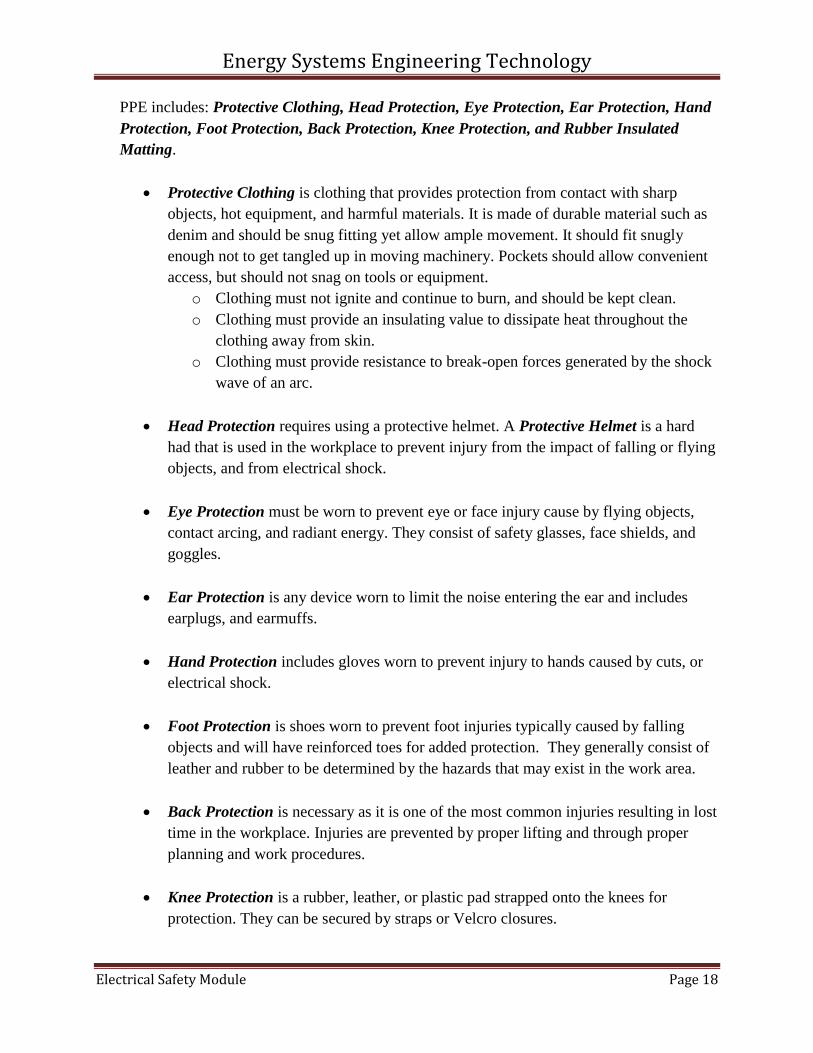
PPE includes: Protective Clothing, Head Protection, Eye Protection, Ear Protection, Hand
Protection, Foot Protection, Back Protection, Knee Protection, and Rubber Insulated
Matting.
Protective Clothing is clothing that provides protection from contact with sharp
objects, hot equipment, and harmful materials. It is made of durable material such as
denim and should be snug fitting yet allow ample movement. It should fit snugly
enough not to get tangled up in moving machinery. Pockets should allow convenient
access, but should not snag on tools or equipment.
o Clothing must not ignite and continue to burn, and should be kept clean.
o Clothing must provide an insulating value to dissipate heat throughout the
clothing away from skin.
o Clothing must provide resistance to break-open forces generated by the shock
wave of an arc.
Head Protection requires using a protective helmet. A Protective Helmet is a hard
had that is used in the workplace to prevent injury from the impact of falling or flying
objects, and from electrical shock.
Eye Protection must be worn to prevent eye or face injury cause by flying objects,
contact arcing, and radiant energy. They consist of safety glasses, face shields, and
goggles.
Ear Protection is any device worn to limit the noise entering the ear and includes
earplugs, and earmuffs.
Hand Protection includes gloves worn to prevent injury to hands caused by cuts, or
electrical shock.
Foot Protection is shoes worn to prevent foot injuries typically caused by falling
objects and will have reinforced toes for added protection. They generally consist of
leather and rubber to be determined by the hazards that may exist in the work area.
Back Protection is necessary as it is one of the most common injuries resulting in lost
time in the workplace. Injuries are prevented by proper lifting and through proper
planning and work procedures.
Knee Protection is a rubber, leather, or plastic pad strapped onto the knees for
protection. They can be secured by straps or Velcro closures.
Energy Systems Engineering Technology
Electrical Safety Module Page 19
Rubber Insulating Matting is a floor covering that provides protection from
electrical shock when working on live electrical circuits over 50 Volts
KEO 1. 14. EXPLAIN what LOCKOUT/TAGOUT is and how it is accomplished.
LOCKOUT/TAGOUT is a process used when electrical power must be removed when
electrical equipment is inspected, serviced, or repaired. The removal of power ensures the
safety of personnel working on or near the equipment. To officially remove power, requires a
process called LOCKOUT/TAGOUT. Lockout is the process of physically locking closed
a breaker feeder to the equipment. Tagout is installing a physical tag to the lockout device to
provide information as to what is locked out and the requirements associated with when and
who can remove the tag and lock restoring power to the equipment. Strict enforcement and
procedures must be followed and understood by all who do the work, supervise, plan and
coordinate all work being performed.
KEO 1. 15. EXPLAIN what FIRE SAFETY is to include: Classes of Fire, In-Plant
Training, and Hazardous Locations.
FIRE SAFETY requires established procedures to reduce or eliminate conditions that could
cause a fire. Guidelines in assessing fire hazards ae provided by NFPA and must be adhered
to. The chance of a fire hazard is greatly reduces by good housekeeping. Rags containing oil,
gasoline, alcohol, shellac, paring, varnish, lacquer, or other solvents may spontaneously
combust and should be kept in a covered metal container.
Classes of Fire and examples of types of extinguishers used on them are depicted
below:
In-Plant Training is required of all personnel so they are acquainted with all fire
extinguishers, sizes, location of, and how to use them.
Hazardous Locations are especially important to the use and application of electrical
equipment. In areas where explosive hazards exist and lead to fire such as flammable
gases, coal, grain, and other types of dust suspended in air require special equipment
and enclosures for all electrical devices. Article 500 of the NEC and Article 400 of
the NFPA cover hazardous locations and requirements that must be met to protect
against fire or explosive conditions.

Energy Systems Engineering Technology
Electrical Safety Module Page 20
KEO 1. 16. EXPLAIN what a CONFINED SPACE is to include: Confined Space
Permits, and Entry Permit Procedures.
A CONFINED SPACE is a space large enough and so configured that an employee can
physically enter and perform assigned work having limited or restricted means for entry and
exit, and is not designated for continuous employee occupancy. Confined spaces include, but
not limited to, storage tanks, process vessels, bins, boilers, ventilation or exhaust ducts,
sewers, underground utility vaults, tunnels, pipelines, and top spaces more than 4 feet deep
such as pits, tubes, ditches, and vaults.
Confined spaces cause entrapment of hazards and life threatening atmospheres through
oxygen deficiency, combustible gases, and/or toxic gases.
KEO 1. 17. EXPLAIN PRECAUTIONS for work around OVERHEAD or UNDER
GROUND POWER LINES.
It is likely that every day, people are killed from accidental contact with overhead power
lines. Overhead power lines are electrical conductors designed to deliver power and they are
located in an above-ground aerial position. These lines are supspended from special
insulators which are attached to special utility poles or metal structures and are owned by
utility companies. They are rated at greater than 600 volts AC. They are located far enough
overhead or buried underground. The maximum overhead line clearance for all non-qualified
individuals is 10 feet plus 4 fee for every 10 kV over 50 kV.
Underground power lines are not buried deep enough so that they cannot be contacted. The
areas they are buried in are marked and specify strict specifications as to where they are and
what is required of qualified individuals if and when any excavation is to be performed.
Utilities need to survey and mark where buried high voltage cables are located and provide
power outages as necessary if and when these conductors are to be worked on. The important
thing for individuals to understand is that it is not safe to dig anywhere there may be buried
power cables. This should be left to qualified utility personnel.
Even in and around residential homes and property, a permit is required before any digging
should be done to prevent damage to cables or electrocution hazards. This needs to be
coordinated with local utilities to include power and gas utilities as well as communication
untilities.

Energy Systems Engineering Technology
Electrical Safety Module Page 21
STEP TWO
Fundamentals of Electrical Safety Course
Skill/Performance Objectives
Skill Knowledge Introduction:
Below are the skill knowledge objectives. How these objectives are performed depend on
equipment and laboratory resources available. With each skill objective it is assumed that a set
of standard test equipment and tools be provided.
For example, to be able to perform electrical work safely, the following tools and equipment will
be required:
1. A measuring device capable of measuring / indicating electrical power sources
2. Appropriate PPE
3. Procedures for safe work
Skill Terminal Objective (STO)
STO 6.1. Given an Electrical Safety Task Checklist, under the direction of an
instructor, complete a series tasks to demonstrate mastery of both knowledge
and skill objectives associated with electrical safety applications.
Skill Enabling Objectives (SEO)

Energy Systems Engineering Technology
Electrical Safety Module Page 22
SEO 1. 1 Perform a Zero Voltage Check
SEO 1. 2 Lockout/Tagout Electrical Equipment
SEO 1. 3 Properly Validate an Electrical Clearance
SEO 1. 4 Demonstrate Proper testing of electrical glove
SEO 1. 5 Demonstrate proper analysis to determine PPE requirements
SEO 1. 6 Demonstrate proper use of Co2 and dry type fire extinguishers
SEO 1. 7 Given a fire scenario, identify the fire type and select the correct extinguisher