energy storage system compressor/expander in a compressed...
9
IET Renewable Power Generation Research Article An approach to reduce the flow requirement for a liquid piston near-isothermal air compressor/expander in a compressed air energy storage system ISSN 1752-1416 Received on 29th January 2016 Revised 19th July 2016 Accepted on 4th August 2016 doi: 10.1049/iet-rpg.2016.0055 www.ietdl.org Perry Y. Li 1 , Mohsen Saadat 1 1 Department of Mechanical Engineering, University of Minnesota, Minneapolis, MN 55455, USA E-mail: [email protected] Abstract: A compressed air energy storage system that uses a high pressure, isothermal air compressor/expander (C/E) has no carbon emission and is more efficient than a conventional system that uses fossil fuels. To be successful, the compressor/ expander must be efficient and has high power density. However, there is a trade-off between efficiency and power density due to heat transfer. The authors’ previous work has shown that by optimising the compression/expansion trajectories in a liquid piston C/E, the power density can be improved by many times without sacrificing efficiency. Yet, to achieve the optimised trajectory, this requires a large liquid piston pump/motor that often operates at low displacement, low efficiency regime. This study proposes that by combining the liquid piston with a solid piston actuated via a hydraulic intensifier, the pump/motor size can be reduced significantly. A case study shows that with an optimal intensifier ratio, the pump/motor size is reduced by 85%, the ratio between maximum and minimum displacements is reduced by 7 times, and the mean efficiency is increased by 2.4 times. A full cycle dynamic simulation shows that the intensifier decreases, for the same pump/motor size, the total cycle time for over 50%, thus doubling the power density of the compressor/expander. 1 Introduction Energy storage is recognised as key to integrating renewable energy into the electrical grid, and compressed air energy storage (CAES) is a potentially cost effective and scalable means of doing so. In the past few years, our research team has been working towards a novel CAES system particularly suited for off-shore wind turbines [1, 2] that stores excess wind energy prior to electricity generation for several hours to several days. The system (Fig. 1-left) uses an open accumulator architecture [3] (whereby the storage vessel contains both liquid and compressed air and by adjusting the liquid volume, the pressure can be maintained regardless of compressed air content) and a near isothermal air compressor/expander (Fig. 1-right) without the use of hydrocarbon fuel. When coupled directly with a wind turbine (via a hydraulic pump) and a synchronous electric generator, wind energy capture can be maximised and output voltage and frequency can be maintained. This would be an improvement over conventional CAES systems, such as the plants in McIntosh, Alabama in the USA or in Huntdorf, Germany, which require natural gas turbines to recover the stored energy with low overall storage efficiency (below 40–50%) [4]. These conventional CAES systems also store compressed air in large underground caverns in such a way that compression heat is lost, and the pressure can only cycle within a limited range (50–80 bar), leading to low energy density. At 200 bar nominal pressure, the proposed system increases energy density by five times. For an introduction to different CAES approaches, including the advanced adiabatic variety, see [5]. For the proposed or other near isothermal CAES systems to be successful, the air compressor/expander must be capable of high pressure (200–300 bar) and is both efficient and power dense. Efficiency is important so that the captured wind energy is not wasted, whereas power density is important to minimise capital expense (CAPEX) and physical footprint. High pressure helps increase both power and energy density. One approach advocated in [6, 7] is to use sprays of tiny water droplets. In our approach, however, this is achieved using a liquid piston and porous media Fig. 1 (Left): System architecture of the open accumulator near-isothermal compressed air energy storage system coupled to a hydraulic wind turbine. (Right): Near-isothermal liquid piston air compressor/expander filled with porous media IET Renew. Power Gener. © The Institution of Engineering and Technology 2016 1
Transcript of energy storage system compressor/expander in a compressed...

IET Renewable Power Generation
Research Article
An approach to reduce the flow requirementfor a liquid piston near-isothermal aircompressor/expander in a compressed airenergy storage system
ISSN 1752-1416Received on 29th January 2016Revised 19th July 2016Accepted on 4th August 2016doi: 10.1049/iet-rpg.2016.0055www.ietdl.org
Perry Y. Li1 , Mohsen Saadat11Department of Mechanical Engineering, University of Minnesota, Minneapolis, MN 55455, USA
E-mail: [email protected]
Abstract: A compressed air energy storage system that uses a high pressure, isothermal air compressor/expander (C/E) hasno carbon emission and is more efficient than a conventional system that uses fossil fuels. To be successful, the compressor/expander must be efficient and has high power density. However, there is a trade-off between efficiency and power density dueto heat transfer. The authors’ previous work has shown that by optimising the compression/expansion trajectories in a liquidpiston C/E, the power density can be improved by many times without sacrificing efficiency. Yet, to achieve the optimisedtrajectory, this requires a large liquid piston pump/motor that often operates at low displacement, low efficiency regime. Thisstudy proposes that by combining the liquid piston with a solid piston actuated via a hydraulic intensifier, the pump/motor sizecan be reduced significantly. A case study shows that with an optimal intensifier ratio, the pump/motor size is reduced by 85%,the ratio between maximum and minimum displacements is reduced by 7 times, and the mean efficiency is increased by 2.4times. A full cycle dynamic simulation shows that the intensifier decreases, for the same pump/motor size, the total cycle timefor over 50%, thus doubling the power density of the compressor/expander.
1 IntroductionEnergy storage is recognised as key to integrating renewableenergy into the electrical grid, and compressed air energy storage(CAES) is a potentially cost effective and scalable means of doingso. In the past few years, our research team has been workingtowards a novel CAES system particularly suited for off-shorewind turbines [1, 2] that stores excess wind energy prior toelectricity generation for several hours to several days. The system(Fig. 1-left) uses an open accumulator architecture [3] (wherebythe storage vessel contains both liquid and compressed air and byadjusting the liquid volume, the pressure can be maintainedregardless of compressed air content) and a near isothermal aircompressor/expander (Fig. 1-right) without the use of hydrocarbonfuel. When coupled directly with a wind turbine (via a hydraulicpump) and a synchronous electric generator, wind energy capturecan be maximised and output voltage and frequency can bemaintained. This would be an improvement over conventionalCAES systems, such as the plants in McIntosh, Alabama in the
USA or in Huntdorf, Germany, which require natural gas turbinesto recover the stored energy with low overall storage efficiency(below 40–50%) [4]. These conventional CAES systems also storecompressed air in large underground caverns in such a way thatcompression heat is lost, and the pressure can only cycle within alimited range (50–80 bar), leading to low energy density. At 200 bar nominal pressure, the proposed system increases energy densityby five times. For an introduction to different CAES approaches,including the advanced adiabatic variety, see [5].
For the proposed or other near isothermal CAES systems to besuccessful, the air compressor/expander must be capable of highpressure (200–300 bar) and is both efficient and power dense.Efficiency is important so that the captured wind energy is notwasted, whereas power density is important to minimise capitalexpense (CAPEX) and physical footprint. High pressure helpsincrease both power and energy density. One approach advocatedin [6, 7] is to use sprays of tiny water droplets. In our approach,however, this is achieved using a liquid piston and porous media
Fig. 1 (Left): System architecture of the open accumulator near-isothermal compressed air energy storage system coupled to a hydraulic wind turbine.(Right): Near-isothermal liquid piston air compressor/expander filled with porous media
IET Renew. Power Gener.© The Institution of Engineering and Technology 2016
1

inserts [8] (Fig. 1-right) to augment heat transfer, to preventleakage of the compressed air, and to reduce dead volume. Auniformly distributed porous media with porosity of 75% has beenshown in experiments to increase the power density by an order ofmagnitude [9, 10] for the same efficiency. In addition, thecompression/expansion trajectories, which are controlled by theliquid piston flow rate, are optimised so as to maximise the powerat a given efficiency; or equivalently, to maximise the efficiency ata given power [11–13]. It has been shown that by merelyoptimising the trajectories, power density can be increased bymany fold over ad-hoc trajectories, such as sinusoidal or linearprofiles, without sacrificing efficiency (see e.g. Fig. 2-top-right).Together with optimising the shape of the compressor/expanderchamber and the distribution of the porous media, the overallpower density can be improved 20 fold over a design that uses ageneric cylindrical shape, uniform porosity distribution anduniform trajectory [14]. All these translate into a more compact andefficient system and lower capital cost, as cost of the compressor/expander will likely scale linearly or to the two-thirds order of itssize. Our current compression/expansion time is between 1 and 2 sfor a pressure of 210 bar and thermodynamic efficiency of 90–95%.
Although optimising the compression/expansion trajectories canimprove the efficiency/power-density trade-off, there is a price tobe paid. Due to the optimal trajectories consisting of fast-slow-fastsegments, the pump/motor for the liquid piston needs to be large toprovide the high flow rates and it must operate at both very highand very low displacements. This is costly and maintainingefficiency for both high and low displacements is challenging. Thispaper proposes and studies the benefits of a combined liquid pistonand solid piston (hydraulic intensifier) approach so one can reapthe benefit of optimised trajectories without needing an excessivelylarge pump/motor.
In Section 2, the Pareto optimal compression/expansiontrajectory concept and its challenges are reviewed. Section 3
presents the proposed combined solid/liquid piston approach.Section 4 uses a case study to illustrate the performance of theproposed approach during compression. Results for expansion aresimilar. A second case study is presented in Section 5 whichincludes the detailed design and the dynamic operation of thesystem. Concluding remarks are given in Section 6.
2 Optimal compression/expansion trajectoriesIn this section, we review the operation of the liquid pistoncompression/expander, how optimising compression/expansiontrajectories improve the efficiency-power density trade-off, and thechallenges to implementing the optimal trajectories.
2.1 Liquid piston compressor/expander
Fig. 1-right is a schematic of the liquid piston compressor/expanderwhich shows the details of the compressor/expander in the dottedbox in Fig. 1-left. The upper portion of its chamber is filled withporous media that increases heat transfer area [8–10]. As the liquid(water in our case) is pumped into the chamber, air above it iscompressed. Similarly, as the compressed air expands, work isextracted via the pump/motor as liquid is withdrawn. Advantagesof the liquid piston compared with a solid piston are (i) liquid canflow through porous media which increase greatly the surface areaand heat capacitances for heat transfer, (ii) it forms a good seal toprevent leakage of compressed air, and (iii) it eliminates potentialdead volumes. Moreover, the velocity of the liquid piston, andhence compression/expansion rates can be controlled bycontrolling the liquid pump/motor.
2.2 Optimal efficiency-power density trade-off
Fig. 2-top-left shows the pressure–volume trajectories of acompression process and an expansion process with a pressure
Fig. 2 (Top-left): Pressure–volume relation during air compression/expansion. (Top-right): Efficiency-power trade-offs with optimised, adiabatic–isothermal–adiabatic, sinusoidal and linear trajectories for a compression ratio of r = 350, a volume varying hA(V) and a fixed total volume, taken from [12].(Bottom-left): Example optimal compression flow rate; and (bottom-right): the resulting pressure and temperature profiles
2 IET Renew. Power Gener.© The Institution of Engineering and Technology 2016
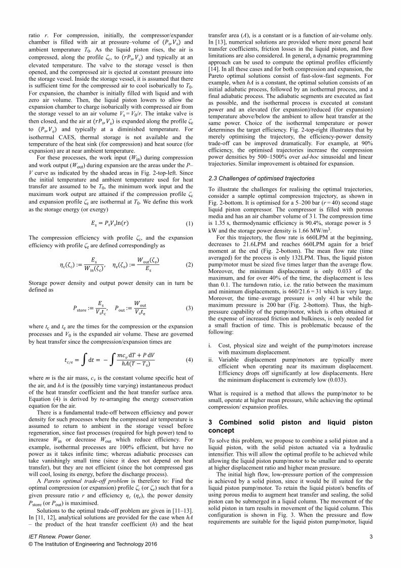
ratio r. For compression, initially, the compressor/expanderchamber is filled with air at pressure–volume of (�0,�0) andambient temperature T0. As the liquid piston rises, the air iscompressed, along the profile ζc, to (��0,�c) and typically at anelevated temperature. The valve to the storage vessel is thenopened, and the compressed air is ejected at constant pressure intothe storage vessel. Inside the storage vessel, it is assumed that thereis sufficient time for the compressed air to cool isobarically to T0.For expansion, the chamber is initially filled with liquid and withzero air volume. Then, the liquid piston lowers to allow theexpansion chamber to charge isobarically with compressed air fromthe storage vessel to an air volume Vs = V0/r. The intake valve isthen closed, and the air at (��0,�s) is expanded along the profile ζeto (�0,�e) and typically at a diminished temperature. Forisothermal CAES, thermal storage is not available and thetemperature of the heat sink (for compression) and heat source (forexpansion) are at near ambient temperature.
For these processes, the work input (Win) during compressionand work output (Wout) during expansion are the areas under the P–V curve as indicated by the shaded areas in Fig. 2-top-left. Sincethe initial temperature and ambient temperature used for heattransfer are assumed to be T0, the minimum work input and themaximum work output are attained if the compression profile ζcand expansion profile ζe are isothermal at T0. We define this workas the storage energy (or exergy)�s = �0�0ln(�) (1)
The compression efficiency with profile ζc, and the expansionefficiency with profile ζe are defined correspondingly as
�c(�c) := �s�in(�c) , �e(�e) := �out(�e)�s (2)
Storage power density and output power density can in turn bedefined as
�store := �s�0�c , �out := �out�0�e (3)
where tc and te are the times for the compression or the expansionprocesses and V0 is the expanded air volume. These are governedby heat transfer since the compression/expansion times are
�c/e =∫d� = −∫��� d�+ � d�ℎ�(� − �0) (4)
where m is the air mass, cv is the constant volume specific heat ofthe air, and hA is the (possibly time varying) instantaneous productof the heat transfer coefficient and the heat transfer surface area.Equation (4) is derived by re-arranging the energy conservationequation for the air.
There is a fundamental trade-off between efficiency and powerdensity for such processes where the compressed air temperature isassumed to return to ambient in the storage vessel beforeregeneration, since fast processes (required for high power) tend toincrease Win or decrease Wout which reduce efficiency. Forexample, isothermal processes are 100% efficient, but have nopower as it takes infinite time; whereas adiabatic processes cantake vanishingly small time (since it does not depend on heattransfer), but they are not efficient (since the hot compressed gaswill cool, losing its energy, before the discharge process).
A Pareto optimal trade-off problem is therefore to: Find theoptimal compression (or expansion) profile ζc (or ζe) such that for agiven pressure ratio r and efficiency ηc (ηe), the power densityPstore (or Pout) is maximised.
Solutions to the optimal trade-off problem are given in [11–13].In [11, 12], analytical solutions are provided for the case when hA– the product of the heat transfer coefficient (h) and the heat
transfer area (A), is a constant or is a function of air-volume only.In [13], numerical solutions are provided where more general heattransfer coefficients, friction losses in the liquid piston, and flowlimitations are also considered. In general, a dynamic programmingapproach can be used to compute the optimal profiles efficiently[14]. In all these cases and for both compression and expansion, thePareto optimal solutions consist of fast-slow-fast segments. Forexample, when hA is a constant, the optimal solution consists of aninitial adiabatic process, followed by an isothermal process, and afinal adiabatic process. The adiabatic segments are executed as fastas possible, and the isothermal process is executed at constantpower and an elevated (for expansion)/reduced (for expansion)temperature above/below the ambient to allow heat transfer at thesame power. Choice of the isothermal temperature or powerdetermines the target efficiency. Fig. 2-top-right illustrates that bymerely optimising the trajectory, the efficiency-power densitytrade-off can be improved dramatically. For example, at 90%efficiency, the optimised trajectories increase the compressionpower densities by 500–1500% over ad-hoc sinusoidal and lineartrajectories. Similar improvement is obtained for expansion.
2.3 Challenges of optimised trajectories
To illustrate the challenges for realising the optimal trajectories,consider a sample optimal compression trajectory, as shown inFig. 2-bottom. It is optimised for a 5–200 bar (r = 40) second stageliquid piston compressor. The compressor is filled with porousmedia and has an air chamber volume of 3 l. The compression timeis 1.35 s, thermodynamic efficiency is 90.4%, storage power is 5 kW and the storage power density is 1.66 MW/m3.
For this trajectory, the flow rate is 660LPM at the beginning,decreases to 21.6LPM and reaches 660LPM again for a briefmoment at the end (Fig. 2-bottom). The mean flow rate (timeaveraged) for the process is only 132LPM. Thus, the liquid pistonpump/motor must be sized five times larger than the average flow.Moreover, the minimum displacement is only 0.033 of themaximum, and for over 40% of the time, the displacement is lessthan 0.1. The turndown ratio, i.e. the ratio between the maximumand minimum displacements, is 660/21.6 = 31 which is very large.Moreover, the time–average pressure is only 41 bar while themaximum pressure is 200 bar (Fig. 2-bottom). Thus, the high-pressure capability of the pump/motor, which is often obtained atthe expense of increased friction and bulkiness, is only needed fora small fraction of time. This is problematic because of thefollowing:
i. Cost, physical size and weight of the pump/motors increasewith maximum displacement.
ii. Variable displacement pump/motors are typically moreefficient when operating near its maximum displacement.Efficiency drops off significantly at low displacements. Herethe minimum displacement is extremely low (0.033).
What is required is a method that allows the pump/motor to besmall, operate at higher mean pressure, while achieving the optimalcompression/ expansion profiles.
3 Combined solid piston and liquid pistonconceptTo solve this problem, we propose to combine a solid piston and aliquid piston, with the solid piston actuated via a hydraulicintensifier. This will allow the optimal profile to be achieved whileallowing the liquid piston pump/motor to be smaller and to operateat higher displacement ratio and higher mean pressure.
The initial high flow, low-pressure portion of the compressionis achieved by a solid piston, since it would be ill suited for theliquid piston pump/motor. To retain the liquid piston's benefits ofusing porous media to augment heat transfer and sealing, the solidpiston can be submerged in a liquid column. The movement of thesolid piston in turn results in movement of the liquid column. Thisconfiguration is shown in Fig. 3. When the pressure and flowrequirements are suitable for the liquid piston pump/motor, liquid
IET Renew. Power Gener.© The Institution of Engineering and Technology 2016
3

can be injected into or withdrawn from the chamber directly as in aregular liquid piston compressor/expander.
The solid piston can also be configured such that its movementchanges the air chamber volume directly in order to avoid the needfor extra liquid in (and volume of) the compression/expansionchamber. A disadvantage of this is that porous media cannot beplaced easily in the volume that would be occupied by the solidpiston.
The solid piston can be actuated by various means, such asmechanically, via a cam shaft, linkage and so on, or hydraulically.Fig. 3 shows the case when it is actuated hydraulically, via a flowintensifier, by the same pump/motor that feeds the liquid piston.The intensifier is configured so that the piston area in the chamberis A2 and the piston area on the side connected to the pump/motoris A1. Typically, A2 > A1. The three-way hydraulic valve switchesthe pump/motor flow to either the liquid piston or the solid piston.
The two modes of operation of the combined solid piston-liquidpiston compressor/expander are shown in Fig. 3. The compressionprocess starts with the solid piston being actuated by the pump/motor via the flow intensifier (Fig. 3-left). Since A2 > A1, toachieve the rate of volume change as determined by the desiredcompression profile, say �2(�), the pump/motor needs only supplythe smaller flow of �1 = (�1/�2)�2. Also, if the chamber pressureis P2, the pump/motor sees the pressure of �1 = (�2/�1)�2, whichis larger than P2.
As compression progresses, both the chamber pressure P2 andpump/motor pressure P1 increase. At some point, the valve isswitched so that the liquid piston is actuated and the solid piston islocked. One possible transition point is when the pump/motorpressure P1 reaches some maximum desired operating pressure ofthe pump/motor. Since the pump/motor is expected to feed theliquid piston, this is likely the final compression pressure of the airto avoid over design. Other transition points are also possible.After the transition, the pump/motor sends all the flow �2(�) asdemanded by the desired compression trajectory to the liquidpiston (Fig. 3-right). In this mode, the pump/motor pressure and thecompression chamber pressure are the same. The compressionprocess continues using the liquid piston until the finalcompression ratio is achieved.
To summarise, the compression process is divided into twophases: In the first (solid piston and flow intensifier) phase, thepump/motor sees a reduced flow rate and an increased pressure(both by a factor of A2/A1); in the second (liquid piston only)phase, the pump/motor experiences the same pressure and flow rateas the original optimal trajectory for the compressed air. The pump/motor size can be reduced because of the lower flow raterequirement. The hydraulic pump/motor can also operate at higherdisplacement and more efficiently during the entire compressioncycle.
One remaining issue is the final portion of the optimaltrajectory that requires a high flow rate and high pressure (see
Fig. 2-bottom). To achieve this with the liquid piston, a largepump/motor is needed to provide a high flow as before. To achievethis with the solid piston/intensifier and a downsized pump, thepump must be capable of a much higher pressure. Neither option isattractive. Fortunately, this final compression portion involves sucha small volume change that even if the flow rate is reduced to themaximum pump flow rate in the first (solid piston) phase, thecompression time is increased negligibly and efficiency is notaffected. Therefore, by slightly modifying the final phase of theoptimal profile, the pump/motor size can be reduced with littleeffect on the thermodynamic trade-off between efficiency andpower.
The expansion case is reversed. The optimal trajectory consists,initially of a short and fast expansion from high pressure (200 bar),followed by a slow expansion, and ending with another portion offast expansion until the low pressure (5 bar) is reached. With theintensifier, the initial portion of the expansion is done using theliquid piston directly. As the chamber air pressure decreases A1/A2times of the maximum allowable pump/motor pressure, the systemswitches to the solid piston and flow intensifier to take advantageof the increase effective expansion rate.
4 Design case studyIn this section, we illustrate how the proposed approach affects thevarious performance characteristics of the liquid piston pump/motor. The average flow rate, average pressure and maximum flowrate of the pump/motor are investigated first, followed byefficiency of the pump/motor.
4.1 Effects on pump flow and mean pressure
To illustrate how the proposed approach affects the average flowrate, average pressure and maximum flow rate of the pump/motor,the r = 40, compression time =1.35 s scenario in Fig. 2-bottom isused. The transition from the solid piston phase to the liquid pistonphase can take place at any moment before the pump pressurereaches the pressure limit of the pump/motor. To avoid over-design, a natural limit is the maximum compressed air pressure.The transition instant is also a function of the intensifier area ratioA2/A1. As an illustration, Fig. 4 shows the flow and pressuretrajectories if the transition pressure is 150 bar and the intensifierratio is A2/A1 = 4.5. Note that the solid piston/intensifier decreasesthe maximum flow requirement to 660LPM/4.5 = 147LPM andraises the mean operating pressure of the liquid pump/motor.
Other choices of A2/A1 and transition pressures can also beused. Figs. 5a–c show how these choices affect the maximum andaverage flow rate of the liquid piston pump/motor. Notice that foreach intensifier ratio A2/A1, both the maximum and average flowrates are minimised when the transition pressure is at the highestallowable value. Choosing this pressure (200 bar) as the transitionpressure (at the pump side), both the average and the maximum
Fig. 3 Concept schematic for a combined solid/liquid piston compressor with the solid piston actuated hydraulically by the same liquid piston pump/motorvia a flow intensifier. Compression with the solid piston (left), and with the liquid piston (right)
4 IET Renew. Power Gener.© The Institution of Engineering and Technology 2016

flow rates are minimised when the intensifier ratio A2/A1 is 7.Lower ratios will require larger pump/motors while higher ratiosreduce the duration when the solid piston can be used due toincreased pump/motor pressure.
At this optimal intensifier ratio, the maximum flow rate isreduced from 660LPM to 94.2LPM so that the pump/motor sizecan be reduced by 85%. The time average pump flow rate is alsoreduced from 132LPM to 34LPM. Note that the maximum flowrate is even less than the mean flow rate without the solid piston/intensifier. The ratio between the maximum and minimumdisplacements (the turndown ratio) is decreased from 31 to 4.4.
This would allow the pump/motor to operate much more efficientlyeven during the low flow rate portion of the cycle.
Fig. 5c shows how the intensifier area ratio and transitionpressure affect the time average pressure of the pump/motor. Foreach intensifier ratio, the average pressure is also maximised whenthe transition pressure is at the maximum (200 bar). With theintensifier ratio of 3, the time average pressure is maximised to 85 bar (from 41 bar). At the intensifier ratio of 7 (which minimisesflow requirements), the time average pressure is still above 75 bar.Thus, an intensifier ratio slightly below 7 would be a goodcompromise between reducing the pump/motor size and increasingthe mean pressure.
Fig. 4 Sample flow and pressure time history of the pump using the solid piston/intensifier approach (A2/A1 = 4.5 and transition pressure of 150 bar arechosen arbitrarily)
Fig. 5 Effect of choices of intensifier area ratios and transition pressure on various characteristics(a) (Top-right): Time average and, (b) (Top-left): Maximum, (c) (Bottom-left): Pump/motor flow rate, and (d) (Bottom-right): average pressure with solid piston/intensifier ofdifferent area ratios and transition pressures: pressure and displacement time histories for the compression process with and without intensifier (area ratio of 7)
IET Renew. Power Gener.© The Institution of Engineering and Technology 2016
5

4.2 Effect on pump/motor efficiency
To evaluate the effect on the pump/motor efficiency, a case with anintensifier area ratio of A2/A1 = 7 and a transition pressure of 200bar is considered. Fig. 5d shows the total efficiency map of atypical variable displacement axial piston pump/motor used in thisstudy. A constant speed of 1800 rpm is assumed as dictated by theopen accumulator system architecture in Fig. 1-left. Volumetricefficiency [15] increases monotonically with displacement, andpeak mechanical efficiency occurs at high displacements (above80%). Hence, in general, the pump/motor is more efficient whenoperating at high displacements. Mechanical efficiency [15]increases as pressure increases while volumetric efficiency dropswith higher pressure due to larger leakages. So, it would bedesirable to shift the process to a higher displacement, higherpressure region in order to improve the total efficiency of thehydraulic pump.
Fig. 5d shows the displacement versus pressure history of theliquid pump/motor over the compression process while performingthe optimal trajectory. When not using the solid piston/intensifier, amajority of the process is performed in the poor efficiency region.The overall pump efficiency is only 27%. When the solid piston/intensifier with an area ratio of 7 is used, the pump operates inmore efficient regions. In this case, the overall pump efficiency isimproved to 65%.
The overall pump/motor efficiency can be further improved intwo ways. First, note that the design methodology to illustrate thesolid piston-liquid piston combination has been simplified.Specifically, the optimal compression/expansion trajectories arecomputed to optimise the thermodynamic efficiency and powertrade-off without consideration of the efficiency of the liquid pistonpump/motor. The intensifier ratio is then designed to duplicate thistrajectory with a smaller pump/motor. A more optimal method is toinclude the possibility of using an intensifier and the efficiency ofthe pump/motor in addition to the thermodynamic efficiency whenoptimising the compression/expansion trajectory. Second, noticefrom Fig. 5d that even with the intensifier, the minimumdisplacement used is below 20% at which the efficiency is only40%. Thus, variable displacement pump/motors that can maintainefficiency at relatively low displacements would increase overallefficiency. In recent years, digital displacement pump/motors [16,17], and adjustable linkage pump/motors [18] have been developedwith exactly this characteristic.
5 Detail design and dynamic simulationIn this section, we conduct a second case study in which weillustrate how the liquid piston air compressor/expander worksdynamically along with other components in the CAES system.This is done by developing a dynamic model of a specific designwith more details and by performing dynamic cycle-by-cyclesimulation of the compression process. Here, the compression/expansion trajectories have been optimised, taking into account theoption of using of the solid piston/intensifier.
A schematic of the specific design including the maincomponents of the intensifier is shown in Fig. 6-top. Twocompression stages are assumed. For the first stage, a conventional1–7 bar solid piston air compressor is used to charge anintermediate buffer tank (at 7 bar) with intake from the atmosphere.The 7–200 bar second stage is performed by the liquid-pistoncompressor/expander with the intensifier. The compression/expansion chamber has a gourd shape, and the mean porosity of thedistributed porous medium is 80%. The shape and porous mediadistribution are chosen according to [14]. A 36 cc/rev hydraulicliquid-piston pump/motor, with a maximum flow rate of 64.8LPM,and an allowable pressure of 200 bar is connected to the chamberthrough a directional valve. Depending on the valve position, thepump/motor flow is directed to the chamber (when U = 0), or to theflow intensifier (when U = 1). The intensifier area ratio is pre-selected to be A2/A1 = 5. An ideal pilot-to-open check valve isplaced on the intensifier path to restrict reverse flow during thetransition of directional valve. The valve configuration, as shown isfor the compression case. For the expansion case, a pilot-to-close
check valve in the opposite direction is needed. The sizing of themain components is summarised in Table 1. The efficiency map ofthe hydraulic liquid-piston pump/motor used in this simulation isshown in Fig. 6-bottom, which is representative of a high-efficiency adjustment linkage variable displacement pump/motordesigned for this application [18]. Compared with the efficiencymap in Fig. 5d, the efficiency remains high even at 20%displacements.
To model the dynamics of the system, transition of thedirectional control valve is modelled as a first-order system with atime constant of 1/6 s. Flow paths in the valve are modelled asorifices with varying areas. The pump/motor displacementactuation is also modelled as a first order system with a timeconstant of 1/8 s. The air in the compression/expansion chamber ismodelled using a 1D, real gas model. Heat transfer to the porousmedia exposed to the air is modelled using the correlation inTable 1. Water is modelled as a compressible liquid with a bulkmodulus of 2.1 GPa. The pilot-to-open check valve is assumed tobe ideal.
5.1 Optimal trajectories
In contrast to the simplistic design procedure in Section 4, thecompression/expansion trajectories are optimised withconsideration of the intensifier and the pressure-flow capability ofthe pump/motor. The compression or expansion times areminimised (to maximise power) while maintaining athermodynamic efficiency of 90%.
Fig. 7 shows the optimal flow trajectories, as functions of thechamber pressure, with and without the use of the 5:1 intensifier,for both compression and expansion. As expected, the optimaltrajectories use the maximum available flow at the beginning andend portions of the compression/expansion consistent with resultsin [11–14]. With the intensifier, the flow is much higher at the lowpressure region compared to the no intensifier case. Forcompression, the transition from using to not using the intensifier isat the critical 40bar (=A1/A2 · 200bar) pressure. Beyond thispressure, the flow is slightly slower, but similar to the no-intensifier case. For expansion, the flow is significantly slowerwith intensifier than without for a longer middle segment of theprocess. The transition from not using to using the intensifier alsooccurs later and at a lower pressure below 40 bar.
The total compression and expansion times, and the total cycletimes are shown in Table 2. Here, compression and expansiontimes correspond to the time to reach 200 bar for compression (or7 bar for expansion); and cycle times include time taken to ejectand intake the 200 bar air, and to charge the chamber with air orwater at 7 bar. With the higher flows seen in Fig. 7, thecompression and expansion times are decreased by 53 and 37%,respectively, with the intensifier. Since the intake of 7 bar air/waterin the compression/expansion cycles occur at low pressure, theintensifier can be activated to increase the flow rate and to decreasethe intake times. These results in 62 and 54% decrease in the totalcompression and expansion cycle times. This means that withintensifier, the same pump/motor results in doubling the powerdensity.
5.2 Dynamic simulation
Dynamic simulation is done using Matlab's Simscape/Simhydraulics environment. The results of the dynamic simulationfor a full compression cycle are shown in Fig. 8. Throughout thecycle, the liquid piston pump/motor displacement is controlled totrack the optimised compression trajectory. Referring to Fig. 8, theflow intensifier is engaged (U = 1) in the first phase of compressionsince the optimal compression trajectory requires a high flow rateat the beginning (phase a). When the pump pressure reaches theallowable pressure of 200 bar, the directional valve is switched to(U = 0) to by-pass the flow intensifier for the rest of compressionprocess until the final desired air pressure (200 bar) is reached(phase b). When the desired 200 bar air pressure is reached, thehigh-pressure poppet valve to the storage vessel opens, and thecompressed air is ejected to the storage vessel (phase c). The
6 IET Renew. Power Gener.© The Institution of Engineering and Technology 2016

ejection phase ends when the chamber air volume falls below thedead volume. At this moment, the high pressure poppet valve isclosed and the liquid piston pump turns into a motor (by reducingdisplacement ratio from +100 to −100%) to retract the liquid pistonat maximum speed. Both the high pressure and low pressure poppetvalves remain closed until the chamber pressure reaches 7 bar atwhich moment, the low pressure poppet valve is opened to the 7 bar intake. Intake continues until the chamber is fully charged.During the initial expansion phase, the small amount of air thatremains in the chamber expands quickly causing its temperature todrop significantly. The first phase of expansion/intake when thepressure is below 200 bar/5 = 40 bar is performed with only theliquid piston (U = 0) (phase d). When the pressure falls below 40 bar, the intensifier/solid piston is engaged (U = 1) and a pilotpressure is applied to the check valve to by-pass it. The liquidpiston is retracted at high speed and air is taken in (phase e). Theuse of the intensifier in this phase decreases the intake time andhence overall cycle time.
The directional control valve takes finite time to switch from U = 1 to U = 0 between phases a and b, during which, cross-port flowis possible. The pressure across the flow intensifier area ratiowould, in the absence of the check valve, cause back flow from thenarrow region of the intensifier to the compression chamber andthe solid piston of the intensifier to retract. The net result would bea significant reduction in the compression chamber pressure. Thisdetrimental effect is avoided with the addition of the check valve.
Fig. 8c indicates that the chamber flow rate decreasesdiscontinuously when the intensifier changes mode (at t = 0.32 and0.88 s). Rapid decrease in chamber flow rate can cause the surfaceof the liquid piston to decelerate quickly. If the deceleration isgreater than 1 g, Rayleigh-Taylor instability [19] may occurcausing splashing and other undesirable events. To avoid thissituation, the trajectories can be modified near the transition. Forexample, the pump flow prior to transition can be reduced at theexpense of a slight increase in cycle time. Similarly, at thetransition pressure of 40 bar, the air volume during compression isgreater than that during intake. Thus, to ensure that the intensifier
Fig. 6 (Top): Schematic of the CAES system with flow intensifier used for a cycle-by-cycle simulation. (Bottom): Efficiency map of the pump/motor as afunction of pressure and displacement (shaft frequency is 30 Hz)
IET Renew. Power Gener.© The Institution of Engineering and Technology 2016
7

positions at the beginning and end of the cycle are the same, thetransitions to using the intensifier may also need to be slightlyadjusted.
The displacement and efficiency of the hydraulic pump/motorduring one compression cycle are shown in Figs. 8b and d. Withthe help of the intensifier, the displacement remains above 45%and the total efficiency remains above 85% except when (at t = 0.8 s) the displacement changes rapidly from +100 to −100%.
6 ConclusionA potential issue with a liquid piston compressor/expander is theneed for a relatively large liquid piston pump/motor that operates atrelatively low mean pressure. This is exacerbated if optimalcompression/expansion trajectories are used to optimise thethermodynamic efficiency-power trade-off. This causes the pump/motor to operate at low displacement and low efficiency regimesfor a significant middle portion of the cycle while requiring largeflows at the initial and final instants. By allowing a part of theprocess to be carried out using a solid piston and an intensifier asproposed, the pump/motor size can be significantly reduced and thepump/motor can be allowed to operate more efficiently at higherdisplacement ratios and higher mean pressures.
The first case study considered in this paper shows that with theintensifier, both the pump/motor size and turndown ratio arereduced by 7 times, mean pressure is doubled, and efficiency isincreased by 2.4 times. A second, more detailed design case studyshows that with an intensifier, the compression and expansion
times are decreased by 53 and 37%; and the total cycle times by 62and 54%. Further improvement of the overall system can beobtained if the operational losses of the pump/motor are optimisedtogether with the compression/expansion process. This willgenerate an optimal combination of pump/motor size, compression/expansion trajectory, intensifier ratio and transition pressure thatoptimises the overall system efficiency.
Dynamic simulations for the second case study indicate thatattention is needed to reduce detrimental effects when theintensifier transitions. For example, a pair of pilot-to-open andpilot-to-close check valves can avoid reverse flow due to cross-flow in the directional control valve; reducing flow prior tointensifier transition or delaying transition can prevent the onset ofRayleigh-Taylor instability of the liquid surface, and ensure theintensifier positions at the beginning and end of the cycle are thesame.
The intensifier as described above is a discrete element to beimplemented between the liquid piston hydraulic pump/motor andthe compression/expansion chamber. However, it can be combinedwith the compression/expansion chamber, or with the liquid pistonhydraulic pump/motor. As part of the compression/expansionchamber, it can be implemented as an element that changes theinternal air volume of the chamber. As part of the pump/motor, itcan be implemented as an intensifier per piston of the pump/motor.Since the pump/motor runs at a much high frequency than thecompressor/expander, this latter implementation has the advantagethat it has a much smaller total volume. Once the implementationapproach is decided, friction in the intensifier (which has beenneglected in this paper) should be included when evaluating theoverall efficiency.
While the description of the solid piston/intensifier approach ismotivated from the high flow/low pressure portion of the optimalcompression/expansion trajectory, the approach can be used totrade-off pressure for flow requirements in general. For example, asolid piston/intensifier can be used to reduce the pump/motor'spressure requirement in the high pressure, low flow region of thecompression/expansion trajectory.
7 AcknowledgmentsThis work was supported by the National Science Foundationunder grant EFRI 1038294 and the University of MinnesotaInstitute of Renewable Energy and Environment (IREE) undergrant RE-0027-11.
Table 1 Summary of the component size used for the aircompression cycle simulationHydraulic pump/motordisplacement 36 cc/revbandwidth 8 Hzmaximum pressure 200 barFlow intensifierarea ratio 5directional valve bandwidth 6 Hzcheck valve idealCompression/expansion chambertotal volumes: chamber/air space 1.8 l/1.5 lmean porosity 83%mean heat transfer surface areadensity
755 m2/m3
heat transfer correlation Nu = 9.7 + 0.0876Re0.792Pr0.33
Pr∼0.7initial pressure: final pressure 7 bar: 200 barwall temperature 298 KOthershaft speed 30 Hzstorage vessel pressure 200 barbulk modulus of water 2.1 GPa
Fig. 7 Optimal compression (left) and expansion (right) trajectories (effective flow rate into the chamber) as functions of chamber pressure, with and withoutusing intensifier, for the system in Fig. 6 and Table 1. Thermodynamic efficiencies are constrained at 90%
Table 2 Compression and expansion times and cycle timeswith and without intensifier
Comp. 7–200 bar
Full comp.cycle
Exp. 200–7 bar
Full exp.cycle
no intensifier, s 1.4 2.9 1.36 2.8with intensifier, s 0.66 1.10 0.85 1.3
8 IET Renew. Power Gener.© The Institution of Engineering and Technology 2016

8 References[1] Saadat, M., Li, P.Y.: ‘Modeling and control of an open accumulator
compressed air energy storage (CAES) system for wind turbines’, Appl.Energy, 2015, 137, pp. 604–616
[2] Li, P.Y., Loth, E., Simon, T.W., et al.: ‘Compressed air energy storage foroffshore wind turbines’. Int. Fluid Power Exhibition (IFPE), Las Vegas, 2011
[3] Li, P.Y., Van de Ven, J.D., Sancken, C.: ‘Open accumulator concept forcompact fluid power energy storage’. ASME-IMECE 2007-#42580, Seattle,WA, 2007
[4] Elmegaard, E., Brix, W.: ‘Efficiency of compressed air energy storage’. The24th Int. Conf. on Efficiency, Cost, Optimization, Simulation andEnvironmental Impact of Energy Systems, 2011
[5] Leithner, R., Nielsen, L.: ‘An introduction to the compressed air energystorage’, in Al-Khoury, R., Bundschuh, J. (Eds.): ‘Computational models forCO2 geo-sequestration & compressed air energy storage’ (CRC Press, 2014)
[6] Coney, M.W., Stephenson, P., Malmgren, A., et al.: ‘Development of areciprocating compressor using water injection to achieve quasi-isothermalcompression’. Int. Compressor Engineering Conf., Paper 1508, PurdueUniversity, 2002
[7] Qin, C., Loth, E.: ‘Liquid piston compression efficiency with droplet heattransfer’, Appl. Energy, 2014, 114, pp. 539–550
[8] Van de Ven, J.D., Li, P.Y.: ‘Liquid piston gas compression’, Appl. Energy,2009, 86, (10), pp. 2183–2191
[9] Yan, B., Wieberdink, J., Shirazi, F., et al.: ‘Experimental study of heat transferenhancement in a liquid piston compressor/expander using porous mediainserts’, Appl. Energy, 2015, 154, pp. 40–50
[10] Wieberdink, J.H.: ‘Increasing efficiency and power density of a liquid pistonair compressor/expander with porous media heat transfer elements’. M.S.-AThesis, Department of Mechanical Engineering, University of Minnesota,Minneapolis, 2014
[11] Sancken, C., Li, P.Y.: ‘Optimal efficiency-power relationship for an air motor-compressor in an energy storage and regeneration system’. ASME 2009Dynamic Systems and Control Conf./Bath PTMC Symp., Hollywood, CA,2009
[12] Rice, A.T., Li, P.Y.: ‘Optimal efficiency-power trade-off for an air motor/compressor with volume varying heat transfer capability’. ASME 2011Dynamic Systems and Control Conf./Bath PTMC Symp., Arlington, VA, 2011
[13] Saadat, M., Li, P.Y., Simon, T.W.: ‘Optimal trajectories for a liquid pistoncompressor/expander in a compressed air energy storage system withconsideration of heat transfer and friction’. Proc.s of the 2012 AmericanControl Conf., Montreal, Canada, 2012
[14] Saadat, M., Li, P.Y.: ‘Combined optimal design and control of a near-isothermal piston air compressor/expander for a compressed air energystorage (CAES) system for wind turbines’. 2015 ASME Dynamic Systemsand Control Conf. DSCC2015-9957, Columbus, 2015
[15] Manring, N.D.: ‘Fluid power pumps and motors: analysis, design andcontrol’ (McGraw-Hill, 2013, 1st edn.)
[16] Ehsan, M., Rampen, W., Salter, S.: ‘Modeling of digital-displacement pump-motors and their application as hydraulic drives for nonuniform loads’, ASMEJ. Dyn. Syst. Meas. Control, 2000, 122, pp. 210–215
[17] Merrill, K.: ‘Modeling and analysis of active valve control of a digital pump/motor’. PhD, ABE Department, Purdue University, W. Lafayette, 2012
[18] Wilhelm, S., Van de Ven, J.D.: ‘Adjustable linkage pump: efficiency modelingand experimental validation’, J. Mech. Robot., 2015, 7, (3), p. 031013
[19] Kull, H.J.: ‘Theory of the Rayleigh-Taylor instability’, Phys. Report (Rev.Section Phys. Lett.), 1991, 206, (5), pp. 197–325Fig. 8 One cycle of compression simulated for the air inside the liquid
piston air compression chamber as a part of CAES system(a) Pressure, (b) Pump displacement and intensifier mode, (c) Pump and chamberflow, (d) Hydraulic efficiency of the pump/motor
IET Renew. Power Gener.© The Institution of Engineering and Technology 2016
9