ENERGY STAR MFHR Simulation Guidelines Version 1 · Minimum requirements for the energy-efficient...
52
August 2010 EPA Version 1.0 ENERGY STAR ® MULTIFAMILY HIGH RISE PROGRAM Simulation Guidelines Version 1.0 August 2010
Transcript of ENERGY STAR MFHR Simulation Guidelines Version 1 · Minimum requirements for the energy-efficient...

August 2010 EPA Version 1.0
ENERGY STAR® MULTIFAMILY HIGH RISE PROGRAM Simulation Guidelines Version 1.0 August 2010

ENERGY STAR MFHR Simulation Guidelines Version 1.0 Page 2
Table of Contents i. Definitions ........................................................................................................................... 3 1. Scope .................................................................................................................................. 5 2. Objectives ........................................................................................................................... 5 3. Modeling Guidelines .......................................................................................................... 5
3.1 General Approach ........................................................................................................ 5 3.2 Performance Rating and Documentation Requirements (G1.2 and G1.4) ................... 7 3.3 Simulation Program (Section G2.2) ............................................................................. 8 3.4 Design Model (Table G3.1, Section 1) ........................................................................ 8 3.5 Schedules (Table G3.1, Section 4) ............................................................................... 9 3.6 Building Envelope: Opaque Assemblies .................................................................... 11 3.7 Building Envelope: Vertical Fenestration .................................................................. 13 3.8 Lighting (Table G3.1, Section 6) ............................................................................... 15 3.9 Thermal Blocks (Table G3.1, Sections 7, 8 and 9) .................................................... 18 3.10 HVAC ...................................................................................................................... 18 3.11 Domestic(Service) Hot Water Systems (Table G3.1, Section 11) ........................... 19
3.11.1 Equipment Type and Efficiency ....................................................................... 19 3.11.2 Hot Water Demand ........................................................................................... 19 3.11.3 Water Savings ................................................................................................... 20
3.12 Hot Water Distribution System .................................................................................... 22 3.13 Receptacles and other plug loads (Table G3.1, Section 12) ........................................ 22 3.14 Elevator Loads ............................................................................................................. 25 3.15 Ventilation and Infiltration ........................................................................................... 26 3.16 HVAC Distribution Losses .......................................................................................... 28 3.17 Fans .............................................................................................................................. 28 3.18 Pumps ........................................................................................................................... 29 3.19 Energy Rates ................................................................................................................ 30 APPENDIX A: Background and Rationale (Informative) .................................................. 31 APPENDIX B: Referenced Standards and Data Sources (Informative) ............................. 49 APPENDIX C: Description of Performance Path Calculator ............................................. 50

ENERGY STAR MFHR Simulation Guidelines Version 1.0 Page 3
i. Definitions ASHRAE 90.1-2007: energy standard for all buildings, excluding low-rise residential buildings. Minimum requirements for the energy-efficient design of high rise multifamily buildings are included within this standard. ASHRAE 90.1-2007 Appendix G (Appendix G): protocols for generating an energy performance rating for buildings that exceed the requirements of ASHRAE 90.1-2007 is included within this appendix. As-Built: same as Final Building. Baseline Building Design: a computer representation of a hypothetical design based on the proposed building project. This representation is used as the basis for calculating the baseline building performance for rating above-standard design. Baseline Building Performance: the annual energy cost for a building design intended for use as a baseline for rating above-standard design. Common Space: any spaces within a building or facility that serves a function in support of the residential part of the building that is not part of a dwelling unit. Common spaces include spaces which may be used by the residents (e.g. corridors and community rooms) or spaces which are used by the staff (e.g. mechanical rooms and offices). Design Team: group of professionals responsible for the final design of a building including, but not limited to: the developer, the general contractor, the architect, design engineers, and Energy Consultant. Dwelling Unit: a single unit providing complete independent living facilities for one or more persons, including permanent provisions for living, sleeping, eating, cooking, and sanitation. Energy Consultant: individual or corporate entity engaged in services supporting developers in earning the ENERGY STAR. These services may include, but are not limited to: design review and consultation, design assistance, energy modeling, field inspections, sub-contractor training, project management, etc. Facility: an entire building or set of buildings and associated grounds that function as a single unique site. Final Building: conditions observed and measured in the completed building. The Final Building energy model must represent the actual observed and measured conditions in the Final building, excluding envelope leakage and duct leakage of in-unit forced air systems.

ENERGY STAR MFHR Simulation Guidelines Version 1.0 Page 4
In-Unit: term used to describe features in the building that are located within the dwelling units. For example, “in-unit lighting” is used to reference lighting located within the apartments. Multifamily High Rise (MFHR): residential buildings consisting of four (4) or more floors of conditioned space above grade. If the building is located on top of nonresidential commercial space, the residential space must occupy more than 50% of the gross heated square footage of the entire building and must be separately metered from the commercial space. Performance Path Calculator: set of spreadsheet calculators provided by the Program to assist Energy Consultants in generating certain specific data inputs needed to complete the energy model for the Baseline Building Design and Proposed Design as referenced in this document, as well as summarize modeling results. Description of the Performance Path calculator are included as Appendix C of this document. Performance Rating Method: a calculation procedure that generates an index of merit for the performance of building designs that substantially exceeds the energy efficiency levels required by ASHRAE Standard 90.1. Performance Target: percent reduction in predicted annual energy costs across all end-uses when comparing the Proposed Building Design to the Baseline Building. Proposed Building Designs must achieve a Performance Target of 15% or more to be eligible to earn the ENERGY STAR. Prerequisites: minimum program standards set by EPA and the Program Administrator to restrict the ability of the Energy Consultant and Design Team to make performance trade-offs that would allow individual building components to fall below minimum acceptable standards during the modeling and/or design of an energy efficient building in order to earn the ENERGY STAR. A Prerequisites Checklist is provided in the Testing and Verification Worksheets. Program Administrator: a third party organization that works with Energy Consultants to implement the ENERGY STAR Multifamily High Rise Program. In many cases this may be a government entity, public utility, or a non-profit organization dedicated to promoting energy efficiency. The Program Administrator must be legally independent from the developers and owners of the building participating in the Program and are required to sign a partner agreement with EPA. Proposed Building Performance: the annual energy cost calculated for a proposed design. Proposed Design: a computer representation of the actual proposed building design or portion thereof used as the basis for calculating the design energy consumption and costs.

ENERGY STAR MFHR Simulation Guidelines Version 1.0 Page 5
1. Scope This document contains the methodology for calculating a performance rating for multifamily buildings in EPA’s ENERGY STAR Multifamily High Rise Program (“Program”). This is not a stand-alone document. It is intended to be used as a supplement to the procedures described in The American Society for Heating and Refrigeration Engineers (ASHRAE) Standard 90.1-2007, Appendix G. ASHRAE Standard 90.1-2007 includes a wide range of building types within its scope. As a result, this standard does not address certain characteristics commonly found in high rise multifamily buildings with sufficient specificity to ensure that energy modeling results are consistent from one energy consultant to the next. This document is designed to address these issues so that the assumptions that must be made to complete these energy models are applied logically and consistently based on all of the features typically found in high rise multifamily buildings. The document is to be used by ENERGY STAR Multifamily High Rise (MFHR) Program Administrators and Energy Consultants to calculate the performance rating of the Proposed Design for each building participating in the program. It may be shared with the developer or property owner if requested.
2. Objectives 1. Ensure a consistent simulation methodology from building to building and from Energy
Consultant to Energy Consultant based on ASHRAE Standard 90.1-2007 Appendix G (“Appendix G”) to evaluate energy efficiency of multifamily buildings.
2. Ensure a consistent approach for handling the simulation of components that are not included in Appendix G, or included without the level of detail needed to support the simulation process.
3. Address those issues that Appendix G leaves for the “rating authority” to decide. The “rating authority” is the Program Administrator in conjunction with EPA.
4. Ensure that the rating process facilitates energy efficient design from the beginning of the design process.
3. Modeling Guidelines
3.1 General Approach Baseline Building Design Components 1. Components of the Baseline Building Design shall comply with ASHRAE Standard
90.1-2007 and other applicable national standards as noted in the text and listed in Appendix B of this document. The most current version of each standard as of 2007 shall be used. Addenda to the referenced standard may be used, but must be explicitly mentioned in the documentation provided by the Energy Consultant, including the related modeling implications.

ENERGY STAR MFHR Simulation Guidelines Version 1.0 Page 6
2. End uses that do not exist in the Proposed Building cannot be included in the Baseline Building Design. For example, if the parking lot in the Proposed Design is not lit, then parking lot lighting power allowance cannot be added to the Baseline energy consumption.
Proposed Design Components Components in the Proposed Design must reflect the actual building components, except where otherwise specified in this document. Components in the Proposed Design must comply with the Prerequisites of this Program as well as applicable state and local codes. If components are not installed during construction, but are required in lease or sales agreement (for example appliances or room air conditioners), then such components may be modeled in the Proposed Design, contributing to the performance rating, subject to review and approval of lease/sales agreement requirement by EPA. As-Built Components Most components in the As-Built or Final Building model, must reflect the actual building components, as verified or measured during inspections. At the completion of the project, these same guidelines can be used to calculate the performance rating for the As-Built model, by substituting “As-Built” where you find “Proposed Design”. Components that are not required to reflect As-Built conditions within the energy model, such as envelope leakage, are specified in the relevant sections below. Although some measured components are not simulated in the energy model, they do have restrictions as described in the Prerequisites. Simulation Methodology 1. The Baseline Building Design and Proposed Design of buildings in the scope of
ASHRAE Standard 90.1-2007 shall be simulated per ASHRAE Standard 90.1-2007 Appendix G and as described in this document.
2. The Baseline Building Design and Proposed Design shall include all spaces in the building (residential, residential-associated, and nonresidential). Residential-associated spaces are: corridors; stairs; lobbies; spaces used for laundry, exercise, residential recreation, parking or otherwise used exclusively by residents, building staff, and their guests, and; offices used by building management, administration or maintenance. This includes all special use areas located in the building to serve and support the residents such as day-care facilities, exercise rooms, dining halls, medical facilities, etc. Nonresidential spaces (commercial and retail) that are privately operated and/or open to the general public, shall also be included in the simulations. However, per Appendix G Section 1(c), energy-related features that have not yet been designed or installed in those spaces shall be described in the Proposed Design exactly as they are defined in the Baseline Building Design. Where the space classification for a space is not known, the space shall be categorized as an office space. Following Table G3.1.1A, the baseline HVAC system type 1 or 2 will still apply to these nonresidential spaces, as buildings participating in this program are predominantly residential. Per exceptions to G3.1.1, if the conditioned floor area of the nonresidential space exceeds 20,000 ft2, then other HVAC systems from Table G3.1.1 can be selected for the baseline for this space.

ENERGY STAR MFHR Simulation Guidelines Version 1.0 Page 7
Use ASHRAE 90.1-2007 as a reference to simulate the energy consumption of special use areas not explicitly described in this document.
3. Separate Baseline Building Design and Proposed Design models shall be created for
each non-identical building in the project. The performance rating shall be calculated individually for each such building.
3.2 Performance Rating and Documentation Requirements (G1.2 and G1.4) The proposed and Baseline Building Performance must each be calculated as the sum of predicted energy cost by end use. The energy consumption for each end use shall be taken from the report generated by the simulation program as described in Section G1.4 of Appendix G and in this document. Some modeling software cannot calculate energy usage for all types of end-uses and technologies proposed for high rise multifamily buildings. Energy use for these features can be determined using separate calculators, custom software, spreadsheets, or other applicable and reasonable means of estimating the energy impact of those features. When calculations of this nature are completed outside of the primary modeling tool, the Energy Consultant must document both the basis for the calculation and how it was incorporated into the final performance rating. Calculations performed outside of the primary modeling tool and not described in this document shall be submitted to the Program Administrator for review and approval. End-use energy consumption used in the Percentage Improvement equation shall be adjusted to incorporate the results of approved calculations done outside of the modeling tool and as described in this document.
Modeling assumptions that are not explicitly specified in Appendix G or this document shall be documented and submitted to the Program Administrator for review and approval. A summary of the performance calculation requirements are listed below but may differ depending on the software tool being used. For example, some tools may be able to automatically calculate exposure-neutral baseline (steps 2a-2c below), or generate a Performance Rating automatically based on the entered parameters of the Proposed Design. 1. Baseline Building Performance shall be determined as follows:
a. Export into a spreadsheet file all total electricity and fuel usages from the energy modeling software tool, for each of the four Baseline Building Designs (actual orientation, and 90, 180, 270 degree rotations, per Table G3.1 of Appendix G). Exception: Baseline Building Performance may be based on the actual building exposure if it is demonstrated that the building orientation is dictated by site conditions.

ENERGY STAR MFHR Simulation Guidelines Version 1.0 Page 8
b. Show usage of each fuel according to at least the following components: lights, internal equipment loads such as appliances and plug loads, service (and domestic) hot water heating equipment, space heating equipment, space cooling equipment, fans and other HVAC equipment (e.g. pumps), and otherwise meet the requirements of Section G1.4 of Appendix G.
c. Average the results of the four building orientations, for each fuel and per each usage component, if applicable.
d. Adjust the result to include the approved calculations performed outside of the energy modeling software tool.
e. If the energy consumption inputs in steps a-d above were expressed in units other than dollars, then after adjusting the simulation outputs as described above, multiply the result by the appropriate fuel rates. This dollar value ($) is your Baseline Building Performance.
2. Proposed Design Building Performance is determined as follows: a. Export into a spreadsheet file all total electric and fuel usages from the energy
modeling software tool (only the actual building orientation is required; no rotations).
b. Adjust the result to include the approved calculations performed outside of the energy modeling software tool.
c. Show usage of each fuel by end use. d. If the energy consumption inputs in steps a-c above were expressed in units other
than dollars, then after adjusting the simulation outputs as described above, multiply the result by the same fuel rates as used for the Baseline simulation. This dollar value ($) is your Proposed Design Building Performance.
3. Calculate the Performance Rating as:
100*(Baseline Building Performance - Proposed Design Building Performance) ÷ (Baseline Building Performance)
3.3 Simulation Program (Section G2.2) The simulation program must meet the requirements of Appendix G, Section G2.2. Programs such as DOE-2, BLAST, EnergyPlus, eQuest, TRACE, HAP and EnergyGauge, have been approved for use in the EPA’s MFHR program. Additional ASHRAE 90.1-2007 Appendix G compliant tools may be accepted upon Program review and approval of the software application.
3.4 Design Model (Table G3.1, Section 1) Modeling all spaces as heated and cooled Every space that is modeled as cooled in the Proposed Building Design simulation shall also be modeled as cooled in the Baseline Building Design. Likewise, every space that is modeled as heated in the Proposed Building Design simulation shall also be modeled as heated in the Baseline Building Design. Unconditioned spaces shall also match between the Proposed Building Design simulation and Baseline Building Design.
ENERGY STAR MFHR Simulation Guidelines Version 1.0 Page 9
1. Model the entire living (including all dwelling unit) space, as well as offices, community rooms and other conditioned spaces other than described in #2 below, as heated and cooled.
2. Do not model cooling in corridors and utility spaces such as mechanical rooms, laundry rooms, etc. unless the spaces are cooled in the Proposed Design.
Modeling components that are not yet designed. Paragraph (c) of Table G3.1, Section 1 and several other sections of Appendix G, outline the approach to modeling components that have not yet been designed. Such provisions do not typically apply to the projects in the Program, since the performance rating is intended to evaluate performance of the final building design. The Baseline Building Design shall be based on the final design of the building, not the initial or preliminary design that was received by the Energy Consultant from the design team. The Baseline Building Design cannot be completed until all the parameters in the Proposed Design that affect the Baseline Building Design are finalized.
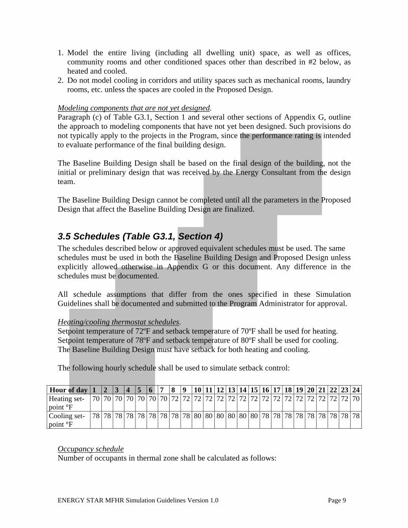
3.5 Schedules (Table G3.1, Section 4) The schedules described below or approved equivalent schedules must be used. The same schedules must be used in both the Baseline Building Design and Proposed Design unless explicitly allowed otherwise in Appendix G or this document. Any difference in the schedules must be documented. All schedule assumptions that differ from the ones specified in these Simulation Guidelines shall be documented and submitted to the Program Administrator for approval. Heating/cooling thermostat schedules. Setpoint temperature of 72ºF and setback temperature of 70ºF shall be used for heating. Setpoint temperature of 78ºF and setback temperature of 80ºF shall be used for cooling. The Baseline Building Design must have setback for both heating and cooling. The following hourly schedule shall be used to simulate setback control:
Occupancy schedule Number of occupants in thermal zone shall be calculated as follows:
Hour of day 1 2 3 4 5 6 7 8 9 10 11 12 13 14 15 16 17 18 19 20 21 22 23 24Heating set-point °F
70 70 70 70 70 70 70 72 72 72 72 72 72 72 72 72 72 72 72 72 72 72 72 70
Cooling set-point °F
78 78 78 78 78 78 78 78 78 80 80 80 80 80 80 78 78 78 78 78 78 78 78 78

ENERGY STAR MFHR Simulation Guidelines Version 1.0 Page 10
Number_Of_Occupants = N*B
Where: N = fraction of occupants present in a given hour, from the table below.
B = number of bedrooms in the thermal zone. Use B=1 for studio dwelling units.
Hour of day
1 2 3 4 5 6 7 8 9 10 11 12 13 14 15 16 17 18 19 20 21 22 23 24
N 1.0 1.0 1.0 1.0 1.0 1.0 1.0 0.9 0.4 0.2 0.2 0.2 0.2 0.2 0.2 0.2 0.3 0.6 0.9 0.9 0.9 1.0 1.0 1.0 Internal gains from occupants in each thermal zone for both Baseline Building Design and
Proposed Design shall be calculated as follows:
Sensible_Occupant_Heat_Gain = 220*N*B Latent_Occupant_Heat_Gain = 165*N*B
Sensible_Occupant_Heat_Gain [Btu/hr] = sensible occupant heat gain for a given hour
Latent_Occupant_Heat_Gain [Btu/hr] = latent occupant heat gain for a given hour
An alternative dwelling unit occupancy schedule included in the software library may be used as approved by the Program Administrator. Lighting Schedule Exterior lighting: Baseline exterior lighting shall be modeled as lit for no more than 12 hours per day. This includes savings due to photosensors that are required per ASHRAE 90.1-2007 Section 9.4.1.3. Interior non-dwelling unit lighting: Baseline lighting in corridors, stairwells and lobbies shall be modeled as lit for 24 hours per day. Performance credit may be taken in the Proposed Design if automatic control devices are installed in these spaces. Performance credit can be taken either by reducing modeled Lighting Power Density (LPD) or by reducing lighting hours of operation. Interior dwelling unit lighting: Baseline and Proposed Design lighting inside dwelling units shall be modeled as lit for 2.34 hours per day. Balcony lighting should use the same schedule as the dwelling units. No schedule-based performance credits may be claimed for lighting inside dwelling units. A custom dwelling unit lighting schedule or dwelling unit schedule included in the software library may be used with the prior Program Administrator approval, provided that the total daily lighting energy consumption (kWh) is not affected by the change.

ENERGY STAR MFHR Simulation Guidelines Version 1.0 Page 11
Hours of operation of Baseline lighting fixtures in areas not identified above may be estimated by the Energy Consultant based on occupancy type of each space, and shall reflect the mandatory control requirements of ASHRAE 90.1-2007 Section 9.4, as modified by the Lighting section (3.8) of these Simulation Guidelines. The lighting schedule for the Proposed Design may be adjusted to account for non-mandatory lighting controls in common spaces as described in the Lighting section (3.8) of these Simulation Guidelines.
3.6 Building Envelope: Opaque Assemblies 1. The properties of the Baseline surfaces shall be determined as follows:
a. Requirements are based on the surface type outlined in ASHRAE 90.1-2007
Appendix G, prescriptive envelope requirements from Table 5.5, and detailed surface descriptions from ASHRAE 90.1-2007 Appendix A. For example, the roof in the baseline shall be modeled as insulated entirely above deck, with continuous insulation R-value from Table 5.5 for the appropriate climate zone. Walls above grade shall have steel framing 16” OC, stucco R-0.08 (exterior layer), 0.625” gypsum board R-0.56, cavity and/or continuous insulation from Table 5.5 for the appropriate climate zone, and 0.625” gypsum board R-0.56 (interior layer). Building Envelope Climate Criteria are covered in Appendix B to ASHRAE 90.1-2007.
b. ‘Residential’ envelope requirements apply only to dwelling units. Examples of spaces that are considered ‘Nonresidential’ for the purpose of envelope requirements include corridors, stairwells, and lobbies.
c. Per ASHRAE Section 5.5.2, if a building contains any semiheated or unconditioned space, then the semi-exterior building envelope of the Baseline Building Design shall comply with the requirements for ‘Semiheated’ space in Tables 5.5. For more information on space types and envelope definitions, see definition of ‘space’ and Figure 5-5 in ASHRAE 90.1-2007, or 5-C of the 90.1-2007 User’s Manual. For the purpose of identifying exterior envelope requirements, both insulated basements and insulated unvented crawlspaces generally are considered ‘conditioned space’ and therefore the ‘Nonresidential’ requirements apply.
d. The surface properties for existing buildings that undergo major renovations shall reflect existing conditions prior to any revisions that are part of the scope of work being evaluated, per Table G3.1 Section 5(f) of Appendix G.
2. If the energy modeling software tool does not allow input of the perimeter heat loss
factor (F-factor), then the slab-on-grade construction that corresponds to the F-factor shall be modeled as is appropriate to the software tool being used.
3. Components in the Proposed Design shall be modeled in accordance with their
actual properties, as described in ASHRAE 90.1-2007 Appendix A.
ENERGY STAR MFHR Simulation Guidelines Version 1.0 Page 12
4. Permanent shading devices (side fins, overhangs, balconies) may be accounted for to calculate energy savings in Proposed Design (per Appendix G).
5. Through wall AC sleeves are not specifically covered in ASHRAE 90.1-2007 and
should be modeled in the Baseline Building Design as having the U-factor required in Table 5-5 for vertical glazing with metal framing (all other). Although an insulated cover is required by the prerequisites, the same Baseline U-factor should be used in the Proposed since the insulated cover is not used every day.
6. Doors that are more than one-half glass are considered fenestration, per Section 3
of ASHRAE 90.1-2007, and shall be modeled as such in both Baseline Building Design and Proposed Design. Consequently, they are not subject to the requirements for opaque doors from Table 5.5.
7. Assemblies such as projecting balconies, perimeter edges of intermediate floor
slabs, and concrete floor beams over parking garages shall be separately modeled in the Proposed Design, per Appendix G Table G3.1, Section 5(a). Such assemblies are considered to be a wall, per wall definition in Section 3 of ASHRAE 90.1-2007, and should be modeled in the Baseline Building Design as having the U-factor required in Table 5-5 for exterior mass walls. A weighted average of the U-factors of these assemblies is acceptable in the simulation. In the Proposed Design, modeling credit will only be given for portions of the plank edge assembly where shelf angles or other continuous metal fastened to the wall are not used. For those portions where the metal piece is offset from the wall and only fastened to the walls at intervals, an overall U-value should be calculated based on an area weighted ratio.
The ASHRAE 90.1-2007 User’s Manual (page G-12) provides the following details on modeling various envelope components that are typically left un-insulated in the Proposed Design (the following procedure applies to these components, even if they are insulated):
All un-insulated assemblies shall be explicitly modeled. Examples include projecting balconies, perimeter edges of intermediate floor slabs, and concrete floor beams over parking garages.
...Projecting balconies and perimeter edges of intermediate floor slabs are considered part of the exterior wall area. …It is acceptable to model them as having the depth of the exterior walls they penetrate. For example, if the wall between the intermediate floor slabs has a total depth of 8”, then these assemblies can be modeled as being 8” thick. If the concrete slab that forms the projecting balcony or intermediate floor slab for a particular floor is 9” thick, then this section of the wall would be modeled in the Proposed Design as a 9” high un-insulated concrete wall that is 8” thick.

ENERGY STAR MFHR Simulation Guidelines Version 1.0 Page 13
For the Baseline Building Design, this portion of the exterior wall would be considered a mass wall complying with the prescriptive requirements for the appropriate climate zone.
3.7 Building Envelope: Vertical Fenestration 1. Per Appendix G, fenestration area shall be distributed on each face of the building in the
same proportion as the Proposed Design, without exceeding 40% of gross above-grade wall area.
2. Baseline fenestration properties shall be determined as follows:
a. When the Proposed Design is a wood-frame building, properties of fenestration in the baseline shall be based on prescriptive requirements of ASHRAE 90.1-2007 for vertical glazing with nonmetal framing. For all other building types, properties of fenestration shall be based on prescriptive requirements for the applicable metal framing. ASHRAE 90.1-2007 requirements for vertical glazing are shown in Tables 5.5-1 through 5.5-8 based on the framing material.
b. For gut rehabilitation projects, the Baseline Building Design shall reflect existing conditions prior to any revisions that are part of the scope of work being evaluated, as described in building envelope section of Table G3.1 of Appendix G.
3. For the Proposed Design, the properties of fenestration specified in the drawings shall be used. These properties must include rated U-factor and SHGC shown on the National Fenestration Rating Council (NFRC) label. NFRC rating reflects the overall performance of the fenestration assembly and includes both frame and glazing of the standard size window. Certification provided by the installer or supplier listing the U-factor or SHGC can be used in lieu of NFRC labels, provided that they comply with Section 5.8.2.2, 5.8.2.4 and 5.8.2.5 of ASHRAE 90.1-2007.
4. Modeling of partially glazed doors: a. Doors that are more than one-half glass:
i. The entire door area shall be counted as vertical fenestration when calculating the vertical fenestration-to-wall ratio.
ii. The door shall be modeled as a single fenestration unit in both the Baseline Building Design and Proposed Design.
iii. The door U-factor and SHGC in the Baseline Building Design shall be determined based on requirements for vertical fenestration in Tables 5.5-1 through 5.5-8, based on the applicable climate zone.
iv. In the Proposed Design, the door U-factor and SHGC shall be modeled as per the NFRC label for the door specified in the final design.
b. Doors that have glazing area of 50% or less: i. Only the glazed portion of the door shall be included when calculating the
vertical fenestration-to-wall ratio. ii. Use one of the following options to model the door:
1. The entire door shall be modeled as opaque in the Baseline and Proposed Building Design. The baseline door U-factor shall be modeled based on the ASHRAE 90.1-2007 requirements for
ENERGY STAR MFHR Simulation Guidelines Version 1.0 Page 14
swinging opaque doors1. The proposed door U-factor shall be modeled as per the NFRC label.
2. Model the Baseline Building Design with a door of identical distribution of opaque/glazed area to the proposed door and apply the ASHRAE 90.1-2007 requirements for swinging opaque doors to the opaque area and the U-factor and SHGC for the appropriate window frame type to the glazing area. The proposed door U-factor shall be modeled as per the NFRC label.
1 The intent of this procedure is to simplify the modeling requirements for doors with less than 50% glazing area and not to create an energy penalty in the analysis for doors with less than 50% glazing area.

ENERGY STAR MFHR Simulation Guidelines Version 1.0 Page 15
3.8 Lighting (Table G3.1, Section 6) General 1. The installed lighting power in the Proposed Design is typically not equal to the total
wattage of the bulbs and must be calculated as described in Section 9.1.3 of ASHRAE 90.1 to include power consumed by the ballast. Per Section 9.1.4 of ASHRAE 90.1, fixtures with screw-base sockets must be modeled based on the maximum labeled wattage for that fixture, regardless of the lamp installed. A screw-based fixture labeled as having a 100 Watt maximum, with an ENERGY STAR qualified 26 Watt CFL installed, must still be modeled as 100 Watts.
2. The lighting schedule and daily operating time described in the Schedules section of this document shall be used.
3. Lighting energy savings credit may be claimed only for hardwired lighting fixtures. 4. Lighting energy savings credit may be claimed for reduced power density only if the
proposed fixtures used to calculate energy savings for lighting-related measures are capable of meeting the recommended light levels (weighted average footcandles) as stated in the 9th edition of the Illuminating Engineering Society Lighting Handbook for the given space type.
ASHRAE Space Type
Recommended Light Levels
(Weighted Avg. Footcandles)
ASHRAE Space Type
Recommended Light Levels
(Weighted Avg. Footcandles)
Apartments 16 Stairs - Active 15 Storage, active 20 Restroom 12 Storage, inactive 8 Office 35
Food Preparation 40 Conference/meeting/multipurpose 30
Dining Area - For Family Dining 23 Electrical/Mechanical 30 Lobby 16 Workshop 50 Corridor/Transition 10 Parking garage 7
5. As per the exception of Appendix G Table G3.1, Section 6, identical lighting power
shall be assumed in the Baseline Building Design and Proposed Design for any lighting that is connected via receptacles and/or not shown or provided for on building plans.
6. Credit for automatic controls can only be taken for spaces where such controls are not required by Section 9.4.1.1 of ASHRAE 90.1.
In-unit Lighting 1. Lighting inside the dwelling units (in-unit lighting) shall be included in the performance
rating calculations. 2. In the Baseline Design, in-unit lighting power density of 2.0 W/SqFt shall be
incorporated into the model. 3. In the Proposed Design, in-unit lighting power density of 2.0 W/SqFt shall be modeled
for rooms or portions of the rooms with no specified hard-wired lighting. Where hardwired in-unit lighting is specified in the Proposed Design (only lighting fixtures

ENERGY STAR MFHR Simulation Guidelines Version 1.0 Page 16
meeting or exceeding ENERGY STAR requirements may be specified, as per the program Prerequisites), the actual installed lighting power density shall be modeled. This lighting power density must take into account the total effective wattage of the installed fixtures and floor area of rooms or portions of the rooms in which they are intended. Hard-wired fixtures in rooms that will be supplemented by lighting that is connected to receptacles can be estimated to provide illumination at a rate of no more than 2 sqft per Watt.
4. The savings shall be modeled as described on the In-Unit Lighting worksheet of the Performance Path Calculator.
Interior Lighting Except In-Unit Lighting 1. Lighting shall be simulated as described in Table G3.1 of Appendix G, using either the
building area or space-by-space method. The space-by-space method often produces higher lighting allowance and is recommended if lighting energy savings credit is claimed by the Proposed Design. If the Building Area method is used, then the Baseline power density of 0.7 W/SF (as per Table 9.5.1, for “Multifamily”) shall be used for all non-dwelling unit spaces. If the space-by-space method is used, then the Baseline Building Design power density in non-dwelling unit spaces shall be modeled as per Table 9.6.1 of ASHRAE 90.1. As per ASHRAE 90.1-2007 Section 9.6.1(a), for types of building spaces not listed in Table 9.6.1, selection of a reasonable equivalent type shall be permitted.
2. In certain cases, lighting power allowance may be increased as described in Section 9.6.2. In order to take advantage of this section, the specified lighting must be installed in addition to general lighting and must be specified on the drawings.
3. Lighting power trade-offs (as per Section 9.5.1 (d) and 9.6.1 (d)) are allowed only between the areas that have hard-wired lighting specified on the Proposed Design drawings. If lighting is specified for only a portion of the space, then the ASHRAE 90.1 lighting power allowance should be assigned to the remainder of the space (for which the lighting is not specified on the drawings) in both Baseline Building Design and Proposed Design. The Interior Lighting worksheet of the Performance Path Calculator shall be used to calculate interior lighting power trade-offs.
4. Automatic lighting controls are a Baseline requirement for all spaces listed in ASHRAE 90.1 Section 9.4.1.1. These spaces include, but are not limited to, janitor closets, laundry rooms, community rooms, offices, public restrooms, and refuse rooms. These spaces are not intended for 24-hour operation and automatic shutoff does not endanger occupant safety. Performance credit may be claimed in the Proposed Design for installing automatic controls where such controls are not required, such as corridors, stairwells, elevators and lobbies, which are considered intended for 24-hour use. See the Schedules section of these Guidelines for more information regarding interior lighting schedules. Appendix G Table G3.2, which describes the allowable lighting power adjustments for automatic controls, is replaced with the following table.
Automatic Control Device Space Type Power Adjustment Percentage Occupancy sensor Hallways/Corridors
Stairwells All other spaces
25%(1) 35% 10%(2)
Occupancy sensor and All spaces Same as with occupancy

ENERGY STAR MFHR Simulation Guidelines Version 1.0 Page 17
programmable timing control
sensor only for the appropriate space type above, or per Table G3.2
(1) 25% power reduction in Hallways per 2005 Building Energy Efficiency Standards of California Energy Code, Section 146 (2) Appendix G, Table G3.2. Exterior Lighting 1. Exterior lighting that is connected to the site utility meters, (e.g., pole fixtures for
walkways and parking, exterior lighting attached to the building) shall be included in the Baseline Building Design and Proposed Design. Exterior lighting performance credit may be claimed only for the areas for which lighting is specified on the drawings. For example, if the parking lot in the Proposed Design is not lit, then no parking lot lighting power shall be modeled in either the Baseline Building Design or Proposed Design. In addition, façade lighting in the Proposed Design that exceeds the Baseline allowance must be modeled, however, no performance credit can be modeled for reductions in façade lighting below Baseline allowance (lighting specified for apartment balconies should be treated as façade lighting). Use the Exterior Lighting worksheet of the Performance Path Calculator for exterior lighting calculations.
2. See the Schedules section of these Guidelines for requirements for modeling automatic controls on exterior lighting in the Baseline.

ENERGY STAR MFHR Simulation Guidelines Version 1.0 Page 18
3.9 Thermal Blocks (Table G3.1, Sections 7, 8 and 9) Requirements 7(b) and 9 of Table G.3.1 in Appendix G are waived. The referenced sections disallow aggregation of dwelling units that have different exposures and/or are adjacent to different types of surfaces (e.g. roof or slab). Under these guidelines, this simplification is allowed but not required. All other Thermal Blocks modeling requirements outlined in Table G3.1 must be followed. For example, common spaces, utility areas and other non-living areas must be modeled as separate thermal blocks. The thermal block configuration must remain identical between the Baseline Building Design and Proposed Design building models.
3.10 HVAC 1. The Baseline and Proposed HVAC system shall be modeled as per Appendix G. For
buildings with fossil fuel, fossil/electric hybrid, or purchased heating in the Proposed Design, the Baseline HVAC system type shall be modeled as a packaged terminal air conditioner (PTAC) with a constant volume fan control and a hot water natural draft fossil fuel boiler. As required by G3.1.3.2, the Baseline HVAC system shall be modeled as having a single boiler if the boiler serves a conditioned floor area of 15,000 SF or less. If the Baseline HVAC system serves more than 15,000 SF of conditioned space, the HVAC system shall be modeled as having two equally sized boilers. For electric and other heating sources, a packaged terminal heat pump (PTHP) shall be used (DX heating instead of a boiler). Electric source heat pumps shall be modeled with electric auxiliary heat as required by G3.1.3.1.
2. Section 8 of Table G3.1, which describes the modeling methodology for projects with
no completed zone design, is not applicable to buildings in the Program because the performance rating is calculated for the final design for which HVAC zones are known.
3. Modeling of the baseline and proposed HVAC system should account for seasonal
variations in efficiency wherever possible. For example, enter the efficiency of the system based on Air-conditioning, Heating and Refrigeration Institute (AHRI) ratings and performance curves for the equipment selected. Appendix G compliant software will compensate for seasonal and part load efficiency variations based on the data provided.
4. All Baseline HVAC equipment shall be modeled using the minimum efficiency levels
as described in Section 6.4. The Baseline equipment capacities shall be oversized by 15% for cooling and 25% for heating as required by G3.1.2.2. In all cases, the same modeling method and/or efficiency units shall be used in the Baseline and Proposed model. For example, if thermal efficiency (not AFUE) is used in the Baseline Building Design, then thermal efficiency (not AFUE) shall also be used for the Proposed Design.

ENERGY STAR MFHR Simulation Guidelines Version 1.0 Page 19
5. Baseline hydronic system shall be modeled as described in Appendix G, including section G3.1.3.2 - G3.1.3.6.
3.11 Domestic(Service) Hot Water Systems (Table G3.1, Section 11)
3.11.1 Equipment Type and Efficiency 1. Baseline and Proposed system type, capacity and fuel shall be the same as specified in
the Proposed Design unless a combination heating/hot water system is used in the final design. In this case, separate stand-alone systems for both heating and hot water meeting the minimum efficiency requirements for each system shall be modeled as the Baseline system. The requirements are as described in Appendix G Table G3.1 Section 11.
2. Baseline system efficiency shall meet the requirements in Section 7.4.2 of ASHRAE 90.1-2007.
3. Water heater efficiency may be described through different parameters including thermal efficiency, combustion efficiency, stand-by loss, recovery efficiency, energy factor, etc. The same units of efficiency shall be used in Baseline Building Design and Proposed Design. If modeling software requires the input of more than one efficiency type (for example Recovery Efficiency and Energy Factor), but only one efficiency type is provided in ASHRAE 90.1-2007 or manufacturer specifications, then the same algorithm shall be used to generate the missing efficiency for both the Baseline Building Design and Proposed Design. All such conversions must be documented and submitted with the model.
4. Unfired storage tank insulation in the Baseline Building Design shall be R-12.5, per ASHRAE 90.1 Table 7.8.
3.11.2 Hot Water Demand 1. Hot water demand in the Baseline Building Design shall be determined based on the
number of occupants in the building when fully occupied assuming one person per bedroom.
Per-person usage of 12/25/44 gal/day shall be used based on low/medium/high usage determined based on appropriate occupancy demographics. Low per-person values are associated with buildings having such occupant demographics as all occupants working, seniors, middle income, and higher population density. High usage is associated with high percentages of children, low income, public assistance, or no occupants working. Usage assumptions must be included in the report. Hot water consumption of clothes washers is not included in the per-dwelling unit usages above, and shall be added to per-dwelling unit usage according to the Clothes Washer Hot Water Usage calculations described below.

ENERGY STAR MFHR Simulation Guidelines Version 1.0 Page 20
2. Hot water demand in the Proposed Design may be reduced since the installed WaterSense fixtures have lower flow rate than required by the Energy Policy Act 1992 (EPACT 1992). The adjusted demand may be calculated as follows:
ProposedHWDemand[Gal/day]=BaselineHWDemand*(0.36+0.54*LFS/2.5+0.1*LFF/2.5)
LFS [GPM] = rated flow rate of the low-flow showerheads specified on the drawings
LFF[GPM] = rated flow rate of the low-flow faucets specified on the drawings 3. Water savings from ENERGY STAR dishwashers may be calculated as follows:
a. Assume proposed water consumption of 860 gal/year per ENERGY STAR dishwasher [this default is used by EPA for ENERGY STAR dishwasher].
b. Calculate annual per-unit hot water demand reduction by subtracting annual hot water usage of the Proposed dishwasher from 1290 gal/year for standard dishwasher [this default is used by EPA for conventional dishwashers].
c. Divide annual per unit savings calculated in the previous step by 365 and multiply by the number of dishwashers in the building to obtain total daily savings for the building.
d. Subtract total daily savings from ProposedHWDemand to obtain adjusted daily demand of the Proposed Design.
e. Use the DHW Demand worksheet of the Performance Path Calculator for reduced hot water demand calculations
4. Clothes Washer Hot Water Usage
Determine hot water usage by each residential clothes washer in Baseline and Proposed Design as follows:
Baseline Design
Hot Water Gal/yr Proposed Design Hot Water Gal/yr
In-dwelling unit clothes washer 0.2*12,179 0.2*5,637
Common space clothes washer 0.2*29,515 0.2*13,661
0.2 = estimated ratio of hot water to total water consumed per year. Values based on annual water consumption of conventional and ENERGY STAR clothes washers, from EPA Savings Calculator for Clothes Washers. Usage assumptions used by EPA for commercial clothes washers are based on 950 loads/year. 5. Convert annual hot water consumption calculated above to hourly values using
appropriate hourly load profile as recommended by the energy modeling software tool.
3.11.3 Water Savings In addition to energy savings associated with reduction in water usage, any measure that results in water savings shall be included in the recommended list of measures. The

ENERGY STAR MFHR Simulation Guidelines Version 1.0 Page 21
following guidelines indicate how these measures should be treated to determine associated savings. Detailed calculations can be found in the Water Savings worksheet of the Performance Path Calculator. 1. All measures that reduce water usage are included in the list of proposed measures. 2. Water savings shall be documented but are not factored into the Performance Target. 3. Examples:
a. Low-Flow Toilets: Include in list of measures. b. Low-Flow Showerheads: Include in list of measures and Performance Target
calculations (energy savings only).
Water cost savings for all measures may be calculated as follows: 1. Begin by calculating baseline usage (in gallons) for each measure. EPAct 1992
flow requirements shall be used for baseline calculations: a. From the following table, determine the baseline flow rate for the
appropriate fixture: b.
Baseline Fixtures Fixture Flow Rate
Toilets (GPF) 1.6 Urinals (GPF) 1.0
Showerheads (GPM) 2.5 Bathroom Faucets (GPM) 2.5 Kitchen Faucets (GPM) 2.5
c. In addition, determine the number of uses per day per occupant and usage duration for the appropriate fixture from the table below:
Fixture Use
Fixture Type Duration (sec) Uses/Day/Occupant Toilets -- 5 Urinals -- 5
Showerheads 450 0.75 Bathroom Faucets 15 5 Kitchen Faucets 60 4
d. Calculate total baseline usage for each fixture type using the calculations
detailed in the Water Savings worksheet of the Performance Path Calculator.
4. Once baseline usage for each measure has been calculated, proposed usage shall be
calculated similarly.
a. GPF Fixtures: Calculate proposed usage using the same usage assumptions as for the baseline, and the actual flow rate of the specified fixtures.
ENERGY STAR MFHR Simulation Guidelines Version 1.0 Page 22
b. GPM Fixtures: Calculate proposed usage using the same usage assumptions as for
the baseline, and the actual flow rate of the specified fixtures. (This will result in a total proposed water usage for cold and hot water combined. Please refer to Section 3.11.2 of the Simulation Guidelines to find guidance on calculating hot water usage savings to include as energy savings.)
c. When on-site collected graywater or rainwater is used for sewage conveyance, the
total estimated annual graywater quantity may be subtracted from the total annual design case water usage. Estimated graywater quantity may not be greater than the total usage of fixtures that utilize it. For example, if graywater will be used only in flush toilets, the estimated graywater quantity cannot be greater than the total annual water usage for toilets.
5. To calculate water cost savings ($), multiply the calculated water savings by the current
local rates for municipal water/sewer service.
3.12 Hot Water Distribution System 1. The same piping area shall be used in the Baseline and Proposed Designs. 2. Hot water setpoint capable of delivering a temperature of 120ºF at the point of use shall
be used in both Baseline Building Design and Proposed Design. 3. If hot water recirculation system is present in the Proposed Design, it shall be included
in both Baseline and Proposed Designs, per Section 11 (h) of Appendix G.
3.13 Receptacles and other plug loads (Table G3.1, Section 12) 1. Non-lighting receptacle loads shall be included in the simulation as specified in the
following table. All such loads, including the fraction of loads contributing to internal heat gain, shall be identical in the Baseline Building Design and Proposed Design, unless the particular load source is impacted by a specific Energy Reduction Measure.
Exception: Dishwashers, clothes washers and clothes dryers shall not be included in either Baseline Building Design or Proposed Design if they are not specified for the project.
2. Where applicable, the appliances in the Baseline Building Design shall be of the same type and capacity as in the Proposed Design, unless specified otherwise. For example, the same refrigerator volume shall be used in both models.
3. Where annual or daily consumption is provided in the table below, it must be converted
into the equivalent design load (Watt or Watt/SF) and hourly schedule as appropriate for the energy modeling software being used.

ENERGY STAR MFHR Simulation Guidelines Version 1.0 Page 23
Load Source Energy Consumption Sensible/ Latent Load
Fraction (4) Refrigerator (1)
529 kWh/yr Baseline Building electricity usage (conventional unit) 423 kWh/yr Proposed Design electricity usage (ENERGY STAR unit)
1.00/0.0
Dishwasher (1)
206 kWh/yr Baseline Building electricity usage (conventional unit) 164 kWh/yr Proposed Design electricity usage (ENERGY STAR unit)
0.60/0.15
Clothes Washer (1)
In-unit clothes washers: 81 kWh/yr Baseline Building electricity usage (conventional unit) 57 kWh/yr Proposed Design electricity usage (ENERGY STAR unit) Commercial clothes washers: 196 kWh/yr Baseline Building electricity usage (conventional unit) 138 kWh/yr Proposed Design electricity usage (ENERGY STAR unit)
0.80/0.0
Cooking (2) (electric stove/range)
604 kWh/year 0.40/0.30
Cooking (2) (gas stove/range)
45 Therms/year 0.30/0.20
Clothes Dryer (2)(5)
Electric Dryer: kWh/yr = [418 + (139*Nbr)]*F Gas Dryer: Electricity: kWh/yr = [38 + (12.7*Nbr)]*F Gas: Therms/yr = [26.5 + (8.8*Nbr)]*F Nbr = Number of Bedrooms in dwelling units. F = scale factor to account for increased number of cycles of common space clothes dryers. F=1 for in-unit clothes dryers. F=2.423 for common space clothes dryers.
Electric Dryer:
0.15/0.05
Gas Dryer: Electricity –
1.0/0.0 Gas –
0.10/0.05
Miscellaneous Dwelling unit Plug Loads (3)
0.5 W/SF or 1.05 kWh/FFA FFA = Finished Floor Area of living space in SF 0.90/0.1

ENERGY STAR MFHR Simulation Guidelines Version 1.0 Page 24
Load Source Energy Consumption Sensible/ Latent Load
Fraction (4) Miscellaneous Non-Dwelling unit Plug Loads (3)
Corridors, restrooms, stairs, and support areas: 0.2 W/SF design; 0.7 kWh/SF annual usage. Offices: 1.5 W/SF design; 4.9 kWh/SF annual usage Other Multifamily Public& Common Areas: 0.5 W/SF design; 1.6 kWh/SF annual usage
1.0/0.0
Notes to table:
(1) Energy consumption of refrigerator, dishwashers and clothes washers is based on information posted at www.energystar.gov, including the Product Lists and Savings Calculators (2) Energy consumption data is per Table 11 of the Building America Research Benchmark Definition, Updated December 29, 2004, as made available at http://www.p2pays.org/ref/36/35765.pdf (3) Plug loads are per Table N2-3 of California’s 2005 Nonresidential ACM Manual; non-dwelling units modeled with a 9 hour/day schedule, dwelling units modeled with a 5.8 hour/day schedule. (4) Sensible and Latent Load Fractions are expressed as the fraction of the annual energy consumption and are based on Table 11 of the Building America Research Benchmark Definition, Updated December 29, 2004, as made available at http://www.p2pays.org/ref/36/35765.pdf (5) Performance credit for heat recovery and reduced mechanical exhaust rates may be awarded for use of condensing driers.

ENERGY STAR MFHR Simulation Guidelines Version 1.0 Page 25
3.14 Elevator Loads In the Baseline Building Design, hydraulic elevators shall be modeled in all buildings up to 6 stories high, geared traction elevators for buildings from 7 to 20 stories high, and gearless traction elevators for buildings taller than 20 stories. In order to take credit for energy savings associated with improvements to the elevator system, baseline and proposed design energy estimates must be completed by a design engineer using a simulation based on first principles, traffic models, and engineering data from empirical studies. This energy model must include energy consumed when the elevator is idling and in stand-by as well as the energy consumed when actively transporting the cabs (loaded and unloaded) based on an appropriate traffic model for the building. Some elevator equipment manufacturers will provide these calculations upon request as part of their design assistance service. When elevator energy usage is modeled using the approach described above, the baseline elevator design shall use the following assumptions:
1. The baseline elevator technology shall be based on number of stories serviced by the elevator as shown in the following table:
Elevator Service Height Baseline Technology 4 to 6 stories hydraulic 7-20 stories geared traction 21+ stories gearless traction
2. Standard efficiency DC motors 3. Variable Voltage Variable Frequency Drive 4. No regeneration of braking power losses 5. Controls based on simple elevator algorithm
a. Continue traveling in same direction if there are remaining calls for service in that direction
b. If no more calls for service in direction being traveled, stop and remain idle, or change direction if there are calls for service in that direction
6. Traction elevators are equipped with counterweights sized at 50% of full load capacity. Hydraulic elevators have no counterweight or hydraulic accumulators.
7. Worm gears for geared traction elevators 8. 2:1 roping scheme
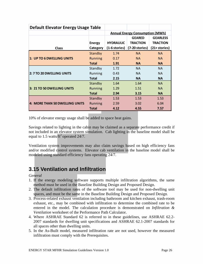
If the elevator system is not modeled using the approach described above, use the default table below to determine the energy consumption associated with the elevators in the building for both the Baseline Building Simulation and the Proposed Design.
ENERGY STAR MFHR Simulation Guidelines Version 1.0 Page 26
Default Elevator Energy Usage TableAnnual Energy Consumption (MWh)
ClassEnergy Category
HYDRAULIC (1‐6 stories)
GEARED TRACTION
(7‐20 stories)
GEARLESS TRACTION (21+ stories)
Standby 1.74 NA NA1: UP TO 6 DWELLING UNITS Running 0.17 NA NA
Total 1.91 NA NAStandby 1.72 NA NA
2: 7 TO 20 DWELLING UNITS Running 0.43 NA NATotal 2.15 NA NAStandby 1.64 1.64 NA
3: 21 TO 50 DWELLING UNITS Running 1.29 1.51 NATotal 2.94 3.15 NAStandby 1.53 1.53 1.53
4: MORE THAN 50 DWELLING UNITS Running 2.59 3.02 6.04Total 4.12 4.55 7.57
10% of elevator energy usage shall be added to space heat gains. Savings related to lighting in the cabin may be claimed as a separate performance credit if not included in an elevator system simulation. Cab lighting in the baseline model shall be equal to 1.5 watts/ft2 operated 24/7. Ventilation system improvements may also claim savings based on high efficiency fans and/or modified control systems. Elevator cab ventilation in the baseline model shall be modeled using standard efficiency fans operating 24/7.
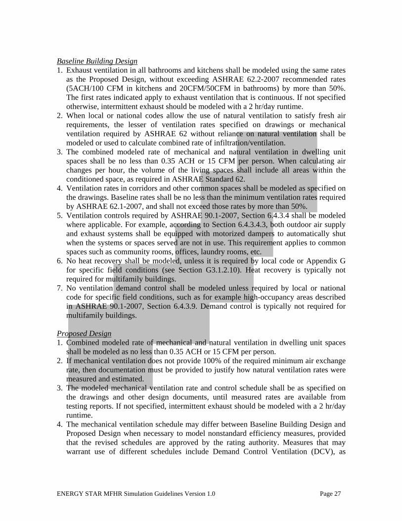
3.15 Ventilation and Infiltration General 1. If the energy modeling software supports multiple infiltration algorithms, the same
method must be used in the Baseline Building Design and Proposed Design. 2. The default infiltration rates of the software tool may be used for non-dwelling unit
spaces, and must be the same in the Baseline Building Design and Proposed Design. 3. Process-related exhaust ventilation including bathroom and kitchen exhaust, trash-room
exhaust, etc., may be combined with infiltration to determine the combined rate to be entered in the model. The calculation procedure is demonstrated on Infiltration & Ventilation worksheet of the Performance Path Calculator.
4. Where ASHRAE Standard 62 is referred to in these guidelines, use ASHRAE 62.2-2007 standards for dwelling unit specifications and ASHRAE 62.1-2007 standards for all spaces other than dwelling units.
5. In the As-Built model, measured infiltration rate are not used, however the measured infiltration must comply with the Prerequisites.
ENERGY STAR MFHR Simulation Guidelines Version 1.0 Page 27
Baseline Building Design 1. Exhaust ventilation in all bathrooms and kitchens shall be modeled using the same rates
as the Proposed Design, without exceeding ASHRAE 62.2-2007 recommended rates (5ACH/100 CFM in kitchens and 20CFM/50CFM in bathrooms) by more than 50%. The first rates indicated apply to exhaust ventilation that is continuous. If not specified otherwise, intermittent exhaust should be modeled with a 2 hr/day runtime.
2. When local or national codes allow the use of natural ventilation to satisfy fresh air requirements, the lesser of ventilation rates specified on drawings or mechanical ventilation required by ASHRAE 62 without reliance on natural ventilation shall be modeled or used to calculate combined rate of infiltration/ventilation.
3. The combined modeled rate of mechanical and natural ventilation in dwelling unit spaces shall be no less than 0.35 ACH or 15 CFM per person. When calculating air changes per hour, the volume of the living spaces shall include all areas within the conditioned space, as required in ASHRAE Standard 62.
4. Ventilation rates in corridors and other common spaces shall be modeled as specified on the drawings. Baseline rates shall be no less than the minimum ventilation rates required by ASHRAE 62.1-2007, and shall not exceed those rates by more than 50%.
5. Ventilation controls required by ASHRAE 90.1-2007, Section 6.4.3.4 shall be modeled where applicable. For example, according to Section 6.4.3.4.3, both outdoor air supply and exhaust systems shall be equipped with motorized dampers to automatically shut when the systems or spaces served are not in use. This requirement applies to common spaces such as community rooms, offices, laundry rooms, etc.
6. No heat recovery shall be modeled, unless it is required by local code or Appendix G for specific field conditions (see Section G3.1.2.10). Heat recovery is typically not required for multifamily buildings.
7. No ventilation demand control shall be modeled unless required by local or national code for specific field conditions, such as for example high-occupancy areas described in ASHRAE 90.1-2007, Section 6.4.3.9. Demand control is typically not required for multifamily buildings.
Proposed Design 1. Combined modeled rate of mechanical and natural ventilation in dwelling unit spaces
shall be modeled as no less than 0.35 ACH or 15 CFM per person. 2. If mechanical ventilation does not provide 100% of the required minimum air exchange
rate, then documentation must be provided to justify how natural ventilation rates were measured and estimated.
3. The modeled mechanical ventilation rate and control schedule shall be as specified on the drawings and other design documents, until measured rates are available from testing reports. If not specified, intermittent exhaust should be modeled with a 2 hr/day runtime.
4. The mechanical ventilation schedule may differ between Baseline Building Design and Proposed Design when necessary to model nonstandard efficiency measures, provided that the revised schedules are approved by the rating authority. Measures that may warrant use of different schedules include Demand Control Ventilation (DCV), as

ENERGY STAR MFHR Simulation Guidelines Version 1.0 Page 28
described in Appendix G. Individual exhaust ventilation in kitchens and bathrooms with manual control or interlocked with lighting switch does not qualify as DCV measure.
5. The mechanical ventilation schedule may also differ between Baseline Building Design and Proposed Design, if the Proposed Design has specified rates significantly greater than ASHRAE 62 recommendations. Although no maximum rates exist for the Proposed Design, they do apply to the Baseline Building Design due to the energy penalty associated with over-ventilating.
3.16 HVAC Distribution Losses 1. Do not model piping or duct losses. Refer to program Prerequisites for specifications
relating to pipe insulation, duct insulation and duct leakage amounts. 2. Projects may pursue performance credit for sealing central stack ventilation ductwork.
To receive this credit, the actual duct leakage measured during the inspection phase of the project as part of the Testing and Verification Protocols conducted on the building, must be below 10 cubic feet per minute measured at 50 Pascals of pressure (CFM50)2 per floor per shaft. To model the energy savings, the actual measured leakage shall be added to exhaust CFM in the Proposed Design. The exhaust leakage in the Baseline Building Design shall be modeled by adding 10 CFM per floor per shaft to the specified exhaust CFM. Based on the Prerequisites, the actual measured exhaust leakage cannot exceed 10 CFM50 per floor per shaft.
3. Performance credit for reduced piping or duct losses may be allowed if the proper documentation is provided to the Program Administrator for review and approval with the description of Baseline and Proposed inputs and calculation procedure.
3.17 Fans Fan motor energy consumption shall be included in the Baseline Building Design and Proposed Design as described below. Modeling additional heating/cooling load from mechanical ventilation is discussed in Ventilation and Infiltration section of this document. Baseline Building Design 1. PTAC/PTHP units serving dwelling units shall be modeled as cycling with load if
continuous in-unit mechanical ventilation is not provided. PTAC/PTHP serving common spaces that provide mechanical ventilation for the space occupants shall be modeled as running continuously when the spaces are occupied, and cycling with load during un-occupied hours.
2. PTAC/PTHP fan power must be modeled as 0.0003 kW/CFM, per ASHRAE 90.1-2007.
3. Supply and exhaust fans that are not part of the HVAC system, such as kitchen and bathroom exhaust fans, laundry make-up fans, trash room exhaust, etc. shall be considered process loads and modeled as follows:
2 In many buildings, the static pressures in the ductwork under normal operating conditions may exceed 50 Pascals of pressure. However, 50 Pascals is the minimum static pressure required for certain pressure-sensitive mechanical controls (such as Constant Air Regulators) to function properly and provides us with a consistent baseline by which we can measure one building’s performance against another’s.

ENERGY STAR MFHR Simulation Guidelines Version 1.0 Page 29
a. For fans that are in the scope of Section 10.4.1 of ASHRAE 90.1, obtain the Baseline Fan Motor Efficiency for the appropriate motor size from Table 10.8. Calculate Baseline fan power as Pfan = bhp x 746 / Fan Motor Efficiency. Actual motor efficiency must be used in the Proposed Design, allowing performance credit for NEMA Premium efficiency motors.
b. The following efficacy shall be used as the Baseline for ENERGY STAR exhaust fans, if such fans are included in the design:
i. range hoods up to 500 CFM, bathroom and utility fans 90-500 CFM, and in-line ventilating fans: 2.3 CFM/Watt
ii. bathroom and utility room fans of 10-80 CFM: 1.2 CFM/Watt c. Fans not covered above do not have to be modeled explicitly. If included in the
model, their design parameters shall be the same as in the Proposed Design, unless specifically allowed otherwise.
Proposed Model 1. Fan energy in the Proposed Design shall be modeled using actual project conditions and
parameters of specified equipment, such as fan bhp, fan motor efficiency, airflow rates, ductwork characteristics, and operation hours. For example, fan power may be calculated as Pfan=bhp x746/Fan Motor Efficiency, or using rated CFM/Watt for actual pressure drop and airflow.
2. Heat recovery devices increase pressure drop in the ductwork, leading to increase in fan energy consumption. This increase should be explicitly modeled in the Proposed Design, to allow evaluating true trade-offs of such systems.
3. Fan motor energy savings from demand control ventilation may be modeled by reducing fan runtime in the Proposed Design compared to the Baseline. For example, reduced fan runtime from installing CO sensors in residential-associated garages may be modeled using 8.4 hr/day fan runtime in Proposed Design, compared to 24 hr/day runtime in the Baseline design.
3.18 Pumps 1. Baseline PTAC/PTHP shall be modeled as described in section G3.1.3.5, including:
a. hot water pump power shall be modeled as 19W/GPM b. pumping system shall be modeled with continuous variable flow c. systems serving 120,000 SF or more shall be modeled with variable-speed drives,
and systems serving less than 120,000 SF shall be modeled as riding the pump curve (piping should include two-way valves)
2. HVAC pumps in the Proposed Design shall be modeled using the actual system parameters including head, capacity control, and pump motor efficiency.
3. Non-HVAC pumps, such as pumps serving DHW may receive performance credit for improvement in motor efficiency or capacity control as described below. a. If pump motor is included in the scope of Section 10 of ASHRAE 90.1 2007:
i. obtain actual pump bhp from drawings or specifications of the Proposed Design
ii. obtain Baseline pump motor efficiency from section 10.4 of ASHRAE 90.1 for appropriate pump motor size
ENERGY STAR MFHR Simulation Guidelines Version 1.0 Page 30
iii. use actual pump design parameters in combination with the Baseline pump motor efficiency as appropriate for the energy modeling software tool being used to model pump in the Baseline
iv. use actual pump design parameters in combination with the actual pump motor efficiency in the Proposed Design
b. Constant flow capacity control may be assumed in the Baseline Building Design, unless required otherwise by ASHRAE 90.1 for the specific design conditions. Actual capacity control may be modeled in the Proposed Design.
c. If the pump motor is not included in the scope of ASHRAE 90.1 Section 10, the pump does not have to be modeled explicitly. If included in the model, its parameters shall be the same in the Baseline and Proposed Design.
3.19 Energy Rates Unless provided otherwise by your Program Implementer, per Appendix G, Section G2.4, use ‘either actual rates for purchased energy or state average energy prices published by DOE’s Energy Information Administration’ in energy simulations of Baseline Design, Proposed Design, and As-Built. The same rate schedule should be used in all simulations. Actual rate schedules and pricing may be used only if savings associated with demand reduction are modeled. Performance credit for the reduced energy cost may be claimed only if the cost reduction is due to the reduced energy consumption or demand. Following this rule, savings associated with sub-metering shall not be included in the performance rating.

ENERGY STAR MFHR Simulation Guidelines Version 1.0 Page 31
APPENDIX A: Background and Rationale (Informative) Section 3.1 General Approach A comparison of national standards (ASHRAE Standard 90.1, ASHRAE Standard 62.1, etc.) to state and local codes (Energy Conservation Construction Code of New York State (ECCC NYS), NYC Building Code, etc.) uncovered differences between national and local requirements. This document was originally developed to support programs administered by the New York State Energy Research and Development Authority and as a result, the initial research conducted to evaluate the discrepancies which might exist between the ASHRAE standards and local codes were based on the New York State Energy Conservation Construction Code and New York City municipal building codes. The following examples are offered to illustrate how state and local codes may vary significantly from the ASHRAE standards. Program participants and administrators should carefully review their own local codes to determine where location-specific discrepancies may impact the overall program success. For example, the ASHRAE 90.1 minimum surface R-value requirements differ from requirements outlined in Section E802.2 of ECCC NYS. The required envelope parameters in both documents depend on climate zone, but NYS is covered by three climate zones in ASHRAE 90.1 and by seven climate zones in ECCC NYS. Ventilation requirements are another example of differences between national and local requirements. ASHRAE Standard 62.2 calls for fixed ventilation air flow for residential kitchens (100 CFM intermittent or 5 ACH continuous per kitchen). The New York City Building Code on the other hand had at one time required that the ventilation rate be proportional to the kitchen area (2 CFM/SF). ASHRAE Standard 90.1 requires heat recovery for certain ventilation systems. There is no such requirement in the ECCC NYS. ENERGY STAR is a nationally recognized label. It is important that the energy rating calculated in this Program be consistent with national methodologies. In order to achieve this, the components in the Baseline Building Design should comply with applicable national standards. Section 3.2 Performance Rating Documentation 1. Section G1.2 of Appendix G suggests calculating percentage improvement as follows:
Percentage Improvement =
100*(Baseline Building Performance - Proposed Building Performance) ÷ (Baseline Building Performance)
Section G1.4 (a) states that Baseline and Proposed Building Performance are calculated by a simulation program. A survey of existing modeling tools indicated that simulation programs cannot handle a variety of improvements and processes in the building. This is recognized by Section G2.5, which allows the rating authority to adopt an exceptional calculation method to demonstrate above-standard performance. There is a need to
ENERGY STAR MFHR Simulation Guidelines Version 1.0 Page 32
develop a consistent way to incorporate the results of these calculations into the percentage improvement equation.
2. Section 6 of Table G3.1 of Appendix G, Proposed Building Performance column, has an exception that requires that unspecified in-unit lighting to be modeled, but then subtracted from the Baseline and Proposed Building Performance when calculating the performance rating. This requirement is inconsistent with the general approach of Appendix G, which includes all regulated and un-regulated end uses in the performance rating calculation. This exception was later waived in the ASHRAE 90.1 addendum a, and is now removed from the requirements of the Program.
Section 3.5 Schedules Appendix G requires the use of schedules capable of modeling hourly variations in occupancy, lighting power, miscellaneous equipment power, thermostat set-points, and HVAC system operation. The schedules should be typical of the Proposed Building type as determined by the designer and approved by the rating authority. The Canadian program C-2000, which was very similar to this Program, confirms the importance of establishing consistent schedule requirements. That program reported the following among the most frequent mistakes in DOE2 models created based on the ASHRAE 90.1 Budget Cost Method: • Schedules for lighting, equipment, HVAC system, etc. were not modeled as defined in
ASHRAE 90.1. • Space temperatures in some zones were unrealistically high. Heating/Cooling Set-point schedule Section C5 of Normative Appendix C of ASHRAE Standard 90.1 mandates the following modeling assumption for building envelope trade-off option:
The thermostat set-points for residential and nonresidential spaces shall be 70ºF for heating and 75ºF for cooling, with night setback temperatures of 55ºF for heating and 99ºF for cooling. ASHRAE Standard 55-192 suggests a heating setpoint of 71ºF and cooling set-point of 76ºF as optimal for human comfort. No setback temperatures are defined.
HERS requires the use of the following assumptions in both the rated and the reference home:
Use temperature control set-points for heating and cooling of 68ºF and 78ºF respectively. Where programmable offsets are available in the rated home, 5ºF temperature control point offsets with an 11pm to 7am schedule for heating and 9am to 3pm schedule for cooling, and with no offsets assumed for the reference home.

ENERGY STAR MFHR Simulation Guidelines Version 1.0 Page 33
Proposed amendment to HERS reduces setback from 5ºF to 2ºF to reflect lower than expected savings from programmable thermostats. The HERS thermostat settings appear more appropriate for residential buildings. Occupancy schedule The Building America Research Benchmark Definition by National Renewable Energy Laboratory (NREL) contains information on a typical occupancy schedule to be used in the HERS benchmark model. The schedule in the document relies on an assumption of peak occupancy of one person per bedroom. 2001 ASHRAE Fundamentals 28.5 suggests using the following estimates for load sizing: “if number of occupants is not known, assume two people for first bedroom and one person for each additional bedroom.” (from Table 9, Summary of Procedures for Residential Cooling Load Calculations). The Building America Research Benchmark Definition assumptions are used for the Program since they represent typical annual conditions, not peak conditions used for load sizing. The average value of peak sensible and latent heat gain from ASHRAE Fundamentals for living area and bedrooms adjusted by the schedule fraction is used to calculate occupant-related heat gains for each hour. Lighting schedule It is important to use a consistent lighting schedule to correctly account for interaction of lighting with heating and cooling, as well as to estimate energy savings associated with energy efficient lighting. Incorporating Lighting and Appliance Energy Consumption into the Home Energy Rating Score – A Pilot Study, by Architectural Energy Corporation quotes survey findings that lamps are lit on average 2.34 hours per day. The Building America website at: http://www.eere.energy.gov/buildings/building_america/docs/lighting_020405.xls contains information on hourly lighting distribution developed by NREL. Worksheet Ltg L0 contains normalized lighting schedules expressed as hourly fractions of daily total lighting energy, and the DOE2 coding required to implement these schedules in hourly simulations. Section 3.6 Building Envelope: Opaque Assemblies Appendix G states that opaque assemblies used for new buildings or additions shall conform to common, lightweight assembly types and shall match the appropriate assembly maximum U-factors in Tables 5.5-1 through 5.5-8.
ENERGY STAR MFHR Simulation Guidelines Version 1.0 Page 34
Section 3.7 Building Envelope: Vertical Fenestration Fenestration Distribution in Baseline Building Design. Appendix G requires that the vertical fenestration areas for new buildings and additions be equal to that in the Proposed Design or 40% of gross above grade wall area, whichever is smaller. Incorporating the 40% limitation of vertical fenestration area encourages reduction of glass area by penalizing the performance rating of projects with large areas of windows. Partially glazed doors The standard requirements related to partially glazed doors are complicated. ASHRAE 90.1 Section 3 contains the following definitions:
fenestration: all areas (including the frames) in the building envelope that let in light, including windows, plastic panels, clerestories, skylights, glass doors that are more than one half glass, and glass block walls. vertical fenestration: all fenestration other than skylights. Trombe wall assemblies, where glazing is installed within12 in. of a mass wall, are considered walls, not fenestration. fenestration area: total area of the fenestration measured using the rough opening and including the glazing, sash and frame. For doors where the glazed vision area is less than 50% of the door area, the fenestration area is the glazed vision area. For all other doors, the fenestration area is the door area. door: all operable opening areas (which are not fenestration) in the building envelope, including swinging and roll-up doors, fire doors, and access hatches. Doors that are more than one-half glass are considered fenestration. (See fenestration.)
According to these definitions, doors that are more than one-half glass are considered fenestration. Such doors are similar to windows with a high frame fraction. For example, a typical 3’x5’ window with aluminum frame has a 15 SF gross area, 4.04 SF of which is taken by the frame, resulting in 27% frame fraction. Similarly, NFRC labels for doors with glazing, just as for windows, include an overall U-factor and SHGC. Doors with glazing area of 50% or less are not considered to be fenestration and must comply with standard requirements for opaque doors. As a result of that, solar gains through glazed portions of such doors will be ignored. This will likely have minimal impact on results, since this glazing constitutes typically a very small fraction of the building fenestration. The glazed areas of such doors will be included in percent fenestration calculations to determine the code requirements for the fenestration U-factor and SHGC. Section 3.8 Lighting

ENERGY STAR MFHR Simulation Guidelines Version 1.0 Page 35
Lighting Power Density Lighting inside dwelling unit units is not regulated by ASHRAE 90.1 as per Exception 9.1.1(b). The general Appendix G rule for any unregulated load is to model it the same in the Baseline Building Design and Proposed Design. However, energy efficient in-unit lighting offers an opportunity to reduce a multifamily building’s lighting load. Therefore, allowing performance credit for in-unit lighting would be beneficial if a proper Baseline and modeling procedure could be established. Table 5-10 of U.S. Lighting Market Characterization: Volume 1: National Lighting Inventory and Energy Consumption Estimate by Navigant Consulting gives the value of 2.0W/SF as a typical installed wattage in multifamily buildings. The LEED ruling to a Credit Interpretation Request allows using 2.0W/SF as a Baseline for lighting performance credit in residential units. Lighting Controls For buildings with total floor area less than 5,000 SF and spaces not lit for 24 hours a day, table G3.2 of Appendix G lists a lighting power adjustment factor of 10% for programmable timing controls and 15% for occupancy sensors or a combination of occupancy sensors and timing controls for buildings with total floor area less than 5,000 SF and spaces not lit for 24 hours a day. For buildings with total floor area greater than 5,000 SF or spaces lit 24 hours a day, no credit is given for timing controls and 10% credit is given for occupancy sensors. The Lighting section of Table G3.1 allows using alternative methods for taking credit for automatic controls used in the Proposed Design if credible technical documentation for the modifications is provided to the rating authority. A paper by Dorene Maniccia et al. (Rensselaer Polytechnic Institute School of Architecture) and Bill Von Neida (EPA ENERGY STAR Buildings Program) ‘The effects of changing occupancy sensor timeout setting on energy savings, lamp cycling, and maintenance costs’ documented energy cost savings from occupancy sensor, including 39%-50% savings in conference rooms, 28%-38% in offices, and 47%-60% in restrooms. California Code Change Proposal by Pacific Gas and Electric Company found at: http://www.energy.ca.gov/title24/2005standards/archive/documents/2002-07-18_workshop/2002-07-18_BILEVEL_LIGHTING.PDF suggests 0.25 lighting power adjustment factor for hallways. These findings are incorporated in the Program requirements as per Section 3.8 to provide more realistic value for savings from the lighting controls. Section 3.9 Thermal Blocks Appendix G requires the following procedure to model the thermal blocks (Table G 3.1(7) of Appendix G):

ENERGY STAR MFHR Simulation Guidelines Version 1.0 Page 36
Where HVAC zones are defined on HVAC design drawings, each HVAC zone shall be modeled as a separate thermal block. Exception: Different HVAC zones may be combined to create a single thermal block or identical thermal blocks to which multipliers are applied, provided that all of the following conditions are met:
(a) The space use classification is the same throughout the thermal block. (b) All HVAC zones in the thermal block that are adjacent to glazed exterior walls face the same orientation or their orientations vary by less than 45 degrees. (c) All of the zones are served by the same HVAC system or by the same kind of HVAC system.
There is an additional requirement for multifamily residential buildings (Table G.3.1(9) of Appendix G):
Residential spaces shall be modeled using at least one thermal block per dwelling unit, except that those units facing the same orientation may be combined into one thermal block. Corner units and units with roof or floor loads shall only be combined with units sharing these features.
This procedure requires including at least 21 thermal blocks to model a building of simple shape. The case study performed to evaluate the impact of detailed zoning on results indicated that while having noticeable effect on the absolute value of the energy consumption by end use, detailing zoning has a relatively small effect on the performance rating of multifamily buildings in the New York State climate. The modeling exercise described above was repeated for a building using the appropriate baseline envelope configuration based on ASHRAE 90.1-2004 and climate data for Baltimore, MD; Atlanta, GA; Portland, OR; and Las Vegas, NV with similar results. In this case, models were built to compare results when every dwelling unit unit is modeled as its own zone, using the ASHRAE 90.1-2004 thermal block approach, and using NYSERDA’s modified thermal block approach. Results of this analysis documented variations in the resulting energy performance target (i.e. percent improvement above the ASHRAE 90.1 baseline) of 0.05 percentage points or less. Using either ASHRAE 90.1 thermal block approach or NYSERDA’s modified thermal block approach demonstrated a variance of as much as 2.0% difference in the estimated heating and cooling consumption of the building, but this variation did not have a significant impact on the predicted net energy improvement from baseline to proposed. For these reasons, energy consultants are cautioned that using a simplified thermal block approach may result in under-predicting actual heating and cooling loads but may still be used for the purposes of determining the incremental improvement in performance resulting from energy improvements installed in the building.
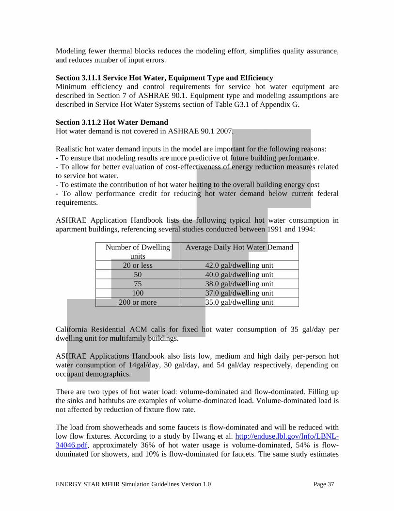
ENERGY STAR MFHR Simulation Guidelines Version 1.0 Page 37
Modeling fewer thermal blocks reduces the modeling effort, simplifies quality assurance, and reduces number of input errors. Section 3.11.1 Service Hot Water, Equipment Type and Efficiency Minimum efficiency and control requirements for service hot water equipment are described in Section 7 of ASHRAE 90.1. Equipment type and modeling assumptions are described in Service Hot Water Systems section of Table G3.1 of Appendix G. Section 3.11.2 Hot Water Demand Hot water demand is not covered in ASHRAE 90.1 2007. Realistic hot water demand inputs in the model are important for the following reasons: - To ensure that modeling results are more predictive of future building performance. - To allow for better evaluation of cost-effectiveness of energy reduction measures related to service hot water. - To estimate the contribution of hot water heating to the overall building energy cost - To allow performance credit for reducing hot water demand below current federal requirements. ASHRAE Application Handbook lists the following typical hot water consumption in apartment buildings, referencing several studies conducted between 1991 and 1994:
Number of Dwelling units
Average Daily Hot Water Demand
20 or less 42.0 gal/dwelling unit 50 40.0 gal/dwelling unit 75 38.0 gal/dwelling unit
100 37.0 gal/dwelling unit 200 or more 35.0 gal/dwelling unit
California Residential ACM calls for fixed hot water consumption of 35 gal/day per dwelling unit for multifamily buildings. ASHRAE Applications Handbook also lists low, medium and high daily per-person hot water consumption of 14gal/day, 30 gal/day, and 54 gal/day respectively, depending on occupant demographics. There are two types of hot water load: volume-dominated and flow-dominated. Filling up the sinks and bathtubs are examples of volume-dominated load. Volume-dominated load is not affected by reduction of fixture flow rate. The load from showerheads and some faucets is flow-dominated and will be reduced with low flow fixtures. According to a study by Hwang et al. http://enduse.lbl.gov/Info/LBNL-34046.pdf, approximately 36% of hot water usage is volume-dominated, 54% is flow-dominated for showers, and 10% is flow-dominated for faucets. The same study estimates
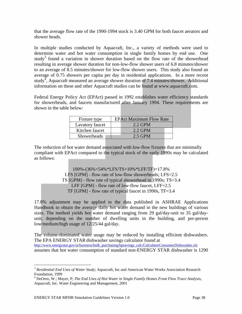
ENERGY STAR MFHR Simulation Guidelines Version 1.0 Page 38
that the average flow rate of the 1990-1994 stock is 3.40 GPM for both faucet aerators and shower heads. In multiple studies conducted by Aquacraft, Inc., a variety of methods were used to determine water and hot water consumption in single family homes by end use. One study3 found a variation in shower duration based on the flow rate of the showerhead resulting in average shower duration for non-low-flow shower users of 6.8 minutes/shower to an average of 8.5 minutes/shower for low-flow shower users. This study also found an average of 0.75 showers per capita per day in residential applications. In a more recent study4, Aquacraft measured an average shower duration of 7.4 minutes/shower. Additional information on these and other Aquacraft studies can be found at www.aquacraft.com. Federal Energy Policy Act (EPAct) passed in 1992 establishes water efficiency standards for showerheads, and faucets manufactured after January 1994. These requirements are shown in the table below:
Fixture type EPAct Maximum Flow Rate Lavatory faucet 2.2 GPM Kitchen faucet 2.2 GPM Showerheads 2.5 GPM
The reduction of hot water demand associated with low-flow fixtures that are minimally compliant with EPAct compared to the typical stock of the early 1990s may be calculated as follows:
100%-(36%+54%*LFS/TS+10%*LFF/TF)=17.8% LFS [GPM] - flow rate of low-flow showerheads; LFS=2.5
TS [GPM] - flow rate of typical showerhead in 1990s; TS=3.4 LFF [GPM] - flow rate of low-flow faucet, LFF=2.5
TF [GPM] - flow rate of typical faucet in 1990s, TF=3.4 17.8% adjustment may be applied to the data published in ASHRAE Applications Handbook to obtain the average daily hot water demand in the new buildings of various sizes. The method yields hot water demand ranging from 29 gal/day-unit to 35 gal/day-unit, depending on the number of dwelling units in the building, and per-person low/medium/high usage of 12/25/44 gal/day. The volume-dominated water usage may be reduced by installing efficient dishwashers. The EPA ENERGY STAR dishwasher savings calculator found at http://www.energystar.gov/ia/business/bulk_purchasing/bpsavings_calc/CalculatorConsumerDishwasher.xls assumes that hot water consumption of standard non-ENERGY STAR dishwasher is 1290
3 Residential End Uses of Water Study; Aquacraft, Inc and American Water Works Association Research Foundation; 1999 4 DeOreo, W.; Mayer, P; The End Uses of Hot Water in Single Family Homes From Flow Trace Analysis, Aquacraft, Inc. Water Engineering and Management, 2001

ENERGY STAR MFHR Simulation Guidelines Version 1.0 Page 39
gal/year. This value may be used to model hot water demand reduction from ENERGY STAR dishwashers, as described in the Program requirements. Water usage of clothes washers is determined by Water Factor, which represents gallons of water used per cubic feet of washer volume in gallons, for each cycle. There is presently no maximum Water Factor required for washers to be ENERGY STAR compliant. However, in the Consortium for Energy Efficiency Residential Clothes Washer Initiative, a minimally compliant residential clothes washer must have a Water Factor of 11.0 or lower. Some ENERGY STAR washers do not comply with this Baseline. The “Gallon/Yr” value in the Proposed Design algorithm is equivalent to the Proposed washer’s Vcf*WF*392 (i.e., Volume*WaterFactor*cycles/yr). Since number of cycles and washer volume is unchanged between the Baseline Building Design and Proposed Design, performance credit for reduced water consumption may be based on the Water Factor of the Proposed washer as compared to some Baseline Water Factor. The Baseline Water Factor is set to 11.0. Section 3.12 Hot Water Distribution System A field study sponsored by NYSERDA showed that piping losses may account for up to 38% of water heating energy in multifamily buildings [Fredric S. Goldner, Home Energy Magazine, http://homeenergy.org/archive/hem.dis.anl.gov/eehem/99/991109.html] Section 3.13 Receptacles and Other Plug Loads Appendix G requires that receptacle and process loads, such as those for office and other equipment, are estimated based on the building type or space type category and are assumed to be identical in the Baseline Building and Proposed Design, except as authorized by the rating authority. A consistent appliance load is important in order to estimate energy savings from ENERGY STAR appliances and interactive effects of reduced heat gains on heating and cooling.. Section 3.14 Elevator Loads Appendix G does not address the savings from energy efficient elevators. A paper by Al-Sharif (October 2007, Elevator World) indicates that elevators typically use 3-5% of the electricity in modern buildings with air conditioning. The percentage would be higher in buildings without air conditioning. There can be a threefold difference in energy consumption between different elevator types, according to research by D.A. Doolard, 1992, as referenced by Al-Sharif. In a project sponsored by the European Commission’s Intelligent Energy Europe Program, the University of Coimbra is currently establishing standardized criteria for evaluating the energy efficiency of elevators. The Energy-Efficient Elevators and Escalators (E4) project is still in development but has resulted in the publication of preliminary documents outlining the methodology for evaluating energy consumption in elevator systems and compiling information on potential energy efficiency improvements that are currently or
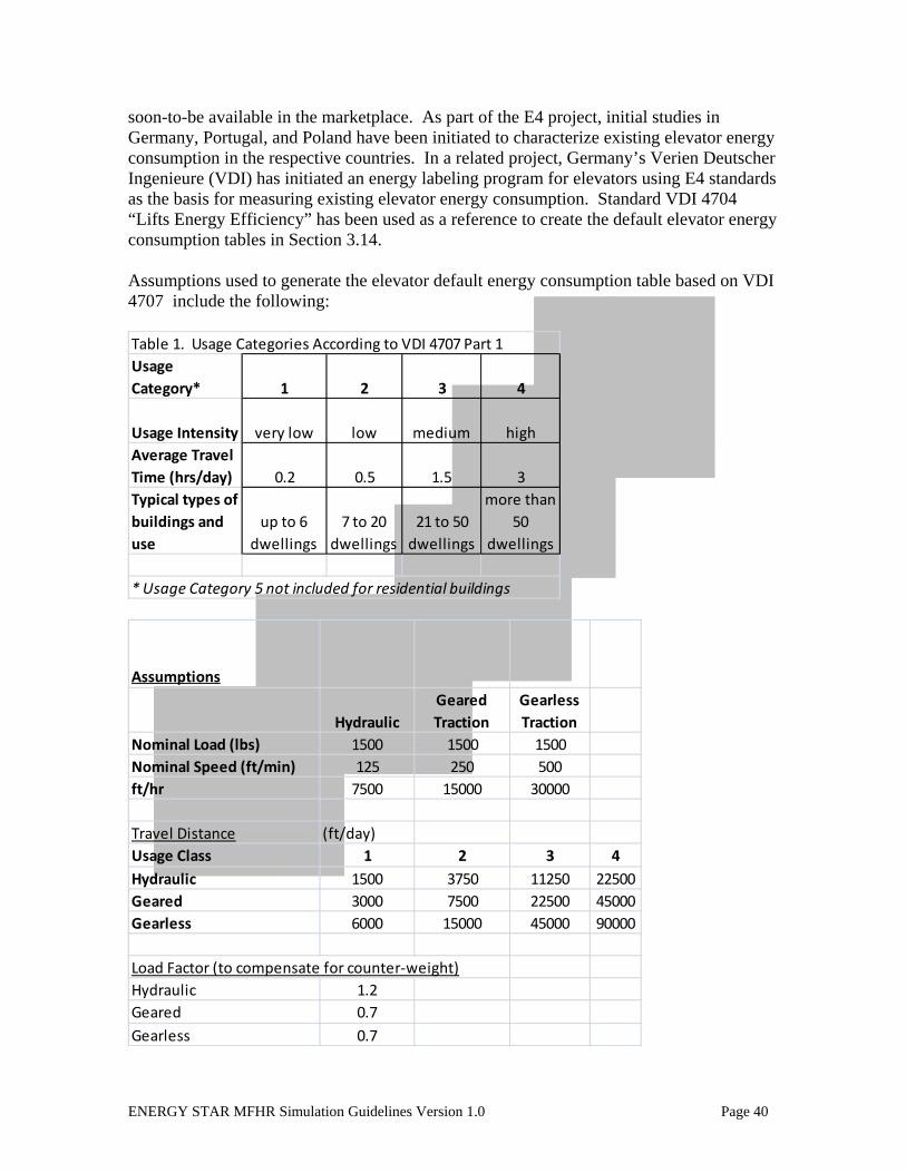
ENERGY STAR MFHR Simulation Guidelines Version 1.0 Page 40
soon-to-be available in the marketplace. As part of the E4 project, initial studies in Germany, Portugal, and Poland have been initiated to characterize existing elevator energy consumption in the respective countries. In a related project, Germany’s Verien Deutscher Ingenieure (VDI) has initiated an energy labeling program for elevators using E4 standards as the basis for measuring existing elevator energy consumption. Standard VDI 4704 “Lifts Energy Efficiency” has been used as a reference to create the default elevator energy consumption tables in Section 3.14. Assumptions used to generate the elevator default energy consumption table based on VDI 4707 include the following: Table 1. Usage Categories According to VDI 4707 Part 1Usage Category* 1 2 3 4
Usage Intensity very low low medium highAverage Travel Time (hrs/day) 0.2 0.5 1.5 3Typical types of buildings and use
up to 6 dwellings
7 to 20 dwellings
21 to 50 dwellings
more than 50
dwellings
* Usage Category 5 not included for residential buildings
Assumptions
HydraulicGeared Traction
Gearless Traction
Nominal Load (lbs) 1500 1500 1500Nominal Speed (ft/min) 125 250 500ft/hr 7500 15000 30000
Travel Distance (ft/day)Usage Class 1 2 3 4Hydraulic 1500 3750 11250 22500Geared 3000 7500 22500 45000Gearless 6000 15000 45000 90000
Load Factor (to compensate for counter‐weight)Hydraulic 1.2Geared 0.7Gearless 0.7
ENERGY STAR MFHR Simulation Guidelines Version 1.0 Page 41
Information on potential improvements to elevator systems for energy efficiency can be found in the E4 publication “WP4: D4.1 Technology Assessment”. Additional information on the E4 project can be found on their website: www.e4project.eu. Information on elevator traffic patterns for modeling purposes can be found in “The Elevator Traffic Handbook”, Dr. Gina Barney, Spon Press, London, 2003. The lighting in the elevator cab offers an additional opportunity to save energy by having the light turn off when the elevator is not in use, and through the use of more efficient lighting. Detailed information on elevator-related savings is presented in a white paper by Harvey M. Sachs, Opportunities for Elevator Energy Efficiency Improvements, sponsored by the American Council for an Energy Efficient Economy (ACEEE). Section 3.15 Ventilation and Infiltration Infiltration ASHRAE 90.1 does not cover infiltration in sufficient detail to support modeling. The standard provides a verbal description of how a building should be sealed but does not provide any references for anticipated leakage areas. The only exception is window and door CFM/SF leakage given in Section 5.4.3.2:
Air leakage shall not exceed 1.0 CFM/SF for glazed swinging entrance doors and for revolving doors and 0.4 CFM/SF for all other products.
ASHRAE Standard 90.1 references ASHRAE Standard 62.1 for outdoor air requirements. Appendix G requires that minimum outdoor air ventilation rates are the same for the proposed and baseline building designs. Infiltration accounts for a significant fraction of heating and cooling energy consumption in multifamily buildings. According to the study Residential Heating And Cooling Load Component Analysis, LBL November 1999, infiltration accounts for 39% of heating energy usage of new multifamily buildings in New York City. Nationally, infiltration is the dominant component of heating loads in multifamily new construction as indicated by the following excerpt:
Infiltration is the largest contributor to heating loads and total loads in new multifamily buildings. Walls and window conduction remain significant for heating loads, while internal gains dominate the cooling loads.
ASHRAE Fundamentals states that the effect of infiltration in high rise buildings is often underestimated. If infiltration airflow rates are normalized by building envelope area instead of by volume, then the envelope air leakage of high rise buildings is similar to typical low-rise houses. However, as buildings become taller, stack driven infiltration/exfiltration becomes the dominant factor in driving air exchange rates. As a result, establishing air barriers between floors and compartmentalizing dwelling unit units

ENERGY STAR MFHR Simulation Guidelines Version 1.0 Page 42
should be a key strategy in controlling infiltration-driven loads in high rise multifamily buildings. This strategy has the added benefit of assisting in controlling unwanted sound and odor migration between floors, dwelling unit units, and common areas. California non-residential Title 24 requires to model infiltration rate of 0.038 CFM per square foot of gross exterior partition (walls and windows) area for the zone in both baseline and proposed design. Infiltration is not modeled if zone supply air quantity is greater than zone exhaust air quantity. There is no guidance on how to model interaction of mechanical ventilation and infiltration in all other cases. Modeling infiltration is difficult for the following reasons: 1. Inputs that are required to support detailed algorithms are not available.
ASHRAE Fundamentals 2001 Section 26.20 states: The air exchange rate of a building may be calculated given (1) the location and leakage function for every opening in the building envelope and between major building zones, (2) the wind pressure coefficients over the building envelope, and (3) any mechanical ventilation airflow rates. These inputs are generally unavailable for all except very simple structures or extremely well studied buildings. Therefore, assumptions as to their values must be made. The appropriateness of these assumptions determines the accuracy of predictions of air exchange rates.
However, this approach ignores the stack effect. Section 26.24 continues this discussion stating:
In large buildings, the air leakage associated with internal partitions becomes very important.
2. The majority of whole-building energy modeling software tools have limited capabilities for modeling infiltration. State-of-the-art review of Whole Building, Building Envelope and HVAC Component and System Simulation and Design Tool Report prepared by AEC and CDH for ARTI provides the following summary of DOE2 capabilities:
Infiltration is modeled using a number of different approaches, including constant air change per hour, which can be scheduled according to the operation of the HVAC system, and the Sherman-Grimsrud infiltration model that takes wind and stack driven infiltration into account. Interzonal ventilation flow is not considered.
This last limitation is very significant for the high rise buildings in the Program, since it does not allow effective modeling of the stack effect.

ENERGY STAR MFHR Simulation Guidelines Version 1.0 Page 43
3. The complexity of calculations further increases due to the presence of mechanical ventilation in the multifamily buildings and its interaction with infiltration, which most of energy modeling software tools cannot account for. The equivalent ventilation/infiltration rate may be estimated using the algorithm described in ASHRAE Fundamentals 2001 p.26.24 as follows:
Qcomb [CFM] = equivalent combined rate to be used as infiltration input in the modeling tool instead of separate infiltration and mechanical ventilation inputs if infiltration/ventilation credit is claimed. Qbal [CFM]= balanced mechanical ventilation flow Qunbal [CFM] = unbalanced mechanical ventilation flow Qinf [CFM] = actual infiltration rate to be verified by field measurements
In the presence of continuous unbalanced mechanical ventilation, the infiltration should not be superimposed (added) to modeled ventilation flow rate, per ASHRAE Fundamentals p.25.21(2) high unbalanced flows cases. Mechanical Ventilation ASHRAE Standard 62-1 2007 Table 6-4 requires that kitchens have 100 CFM intermittent or 50 CFM continuous exhaust ventilation. Private bathrooms must have 50 CFM intermittent or 25 CFM continuous exhaust. However, due to standard duct installation and sealing practice, systems sized to meet this code requirement regularly exceed it. Duct leakage is almost always significant in mechanical ventilation systems. Even in buildings where special attention is made to comply with code requirements, leakage can result in additional exhaust of 10 CFM per fan.5 Such leakage creates the potential for energy savings in such buildings. Local Code requirements often differ from national requirements. For example, Article 6, Section 27-750 and Article 8 Section 27-758 of NYC Code that was in effect until 2008 required that kitchens with floor area greater than 59 SF have natural ventilation; if the area is less than 59 SF, then either natural or mechanical ventilation should be provided. If required, kitchen exhaust ventilation had to be delivered at a rate of 2 CFM/SF, with provision for intake of air. Bathrooms had to be ventilated at a rate of 50 CFM per toilet if natural ventilation is not available. Natural ventilation referenced by code is usually provided by outside air entering the space through windows. This method of ventilation may lead to significant energy loss and does not ensure good air quality, because the actual air flow through an opened window varies depending on weather conditions such as air temperature, wind, etc, as well as building and space characteristics including stack effect, space compartmentalization, and occupant behavior.
5 Preliminary findings of study conducted by Steven Winter Associates in December 2007

ENERGY STAR MFHR Simulation Guidelines Version 1.0 Page 44
Section 27-756 of NYC Code calls for required ventilating systems to be kept in operation at all times when the building or space is being used in a normal manner in accordance with the purpose for which it was intended. This requirement may be interpreted as allowing demand control of ventilation that would shut off the system when the space is not occupied, but most design engineers understand it as requiring continuous exhaust. High performance buildings should be air tight to reduce uncontrolled infiltration. Fresh air should be supplied through mechanical ventilation at rates meeting but not exceeding code requirements and adequate to maintain good air quality. “Energy-Efficient Ventilation for Dwelling unit Buildings,” a report prepared by Lawrence Berkeley National Laboratory as part of Rebuild America Guide Series, provides valuable insight into the role of ventilation in the building energy consumption and the related best practices. (http://epb.lbl.gov/Publications/energy_eff_ventilation.pdf). The report is intended as a retrofit guide; however many of the report recommendations listed below are relevant for new construction as well:
High Rise Dwelling unit Building Retrofit Recommendations • Minimize supply air to corridors • Weather-strip dwelling unit entryway doors (unless supply air is intended to move under doors) • Install continuous bath or kitchen exhaust systems with constant air regulators • Introduce supply air locations in very airtight dwelling units • Locate supply air behind radiators, and direct the airflow upwards • Seal the top of elevator shafts where allowed by code • Under-cut bedroom and bathroom doors to allow air movement between rooms • Use blower doors to identify air leakage paths between dwelling units • Seal leaky ducts and building envelopes • Isolate dwelling units from garbage chutes, stairwells, elevators, and parking garages • To minimize retrofit costs, compartmentalize tall high rise buildings at every third floor rather than at each floor.
Natural ventilation components include operable windows and louvers, air vents and “trickle ventilators” and automatic (variable area) inlets. Using operable windows as source of supply air in dwelling units may lead to “… extreme discomfort and energy waste ….during the heating season”. Trickle ventilators and automatic inlets are recommended practice, as described on pages 56-57 of the guide. Some new multifamily buildings have exhaust-only dwelling unit ventilation systems. According to the guide, “An exhaust-only system removes air from the dwelling units, while the supply air enters directly from outside. All too often, however, depending on the locations of the air leakage sites, the supply air may enter from the corridor, or from surrounding dwelling units.”

ENERGY STAR MFHR Simulation Guidelines Version 1.0 Page 45
The guide warns that “If the building is too tight or there are insufficient air openings, either the suction pressure (hence, electrical energy costs) will rise or the fan will be unable to deliver the design air flow rate. High levels or under-pressure may cause unwanted noise and drafts as well as cause combustion flues to back draft, and may permit radon and other soil gases to enter the building. Therefore, excessive under-pressure must be avoided.” If dwelling unit ventilation design relies on supply air from corridors then “...doors need to be undercut to allow air flow between the supply air inlets and the exhaust grills”. This may interfere with dwelling unit compartmentalization and is often defeated by occupants when undercuts are intentional. The guide also warns that “While corridor supply is common in practice, it may be in violation of fire codes.” The guide suggests that “the ideal balanced ventilation strategy reduces infiltration, minimizes interior airflows, and provides individually controlled supply and exhaust ventilation for each dwelling unit. Sometimes, an intentional flow imbalance may be introduced to put the dwelling units in a light negative pressure, and to reduce odor migration into hallways. Balanced ventilation systems are popular in both high and low-rise buildings, especially in severe climate regions where worthwhile energy recovery is possible.” Section 3.16 HVAC Distribution Losses Appendix G does not provide details on how distribution systems should be modeled, other than the statement in Section G3.1.3.6 that piping losses shall not be modeled in either the Baseline Building Design or Proposed Design for hot water, chilled water, or steam piping. Not modeling piping losses creates the following problems: 1. Ignoring piping losses is equivalent to assuming 100% distribution efficiency of the hydronic system. As a result, if forced air system distribution losses are modeled and the forced air system is compared to the hydronic system, the modeling results will be misleading due to unequal modeling assumptions. 2. There are no means to receive performance credit for distribution-related improvements. The issue is complicated by the limited capability of modeling tools to estimate distribution losses. Air Distribution Systems, Codes and Standards Enhancement (CASE) Study, PG&E, November 28, 2000 http://www.newbuildings.org/downloads/codes/AirDistribution.pdf states: DOE2.1E needs to be significantly enhanced for duct efficiency modeling. Currently, there are considerable problems with the algorithms, and the keywords are complex, difficult to use, and highly sensitive to error. Algorithm problems include: - All leakage occurs on the supply side of the system - All losses go to a single zone - Only one system can have losses to a given zone - Building and zone infiltration is not sensitive to duct leakage.

ENERGY STAR MFHR Simulation Guidelines Version 1.0 Page 46
State of the Art Software Review provides the following summary of DOE2 capabilities: DOE 2.1 calculates distribution losses as a function of the total system capacity. This value is held constant throughout the simulation. The energy gain or loss from the duct system is not added or subtracted from any zone, and is therefore inconsequential. Supply side losses are only considered. DOE 2.2 allows the specification of a duct air loss and a duct conductance. Duct losses/gains are added to a plenum or zone containing the ducts, affecting the duct zone temperature and magnitude of the duct losses. Duct losses to the plenum affect the return air temperature in plenum return systems. The duct loss calculations are applied to the supply duct only. EnergyPlus allows energy consultants to model air distribution loss for a single constant volume HVAC system per building and calculates both supply and return duct losses. However, interaction between mechanical ventilation and infiltration is not accounted for – the infiltration is not modeled (assumed to be 0) whenever HVAC fans are operating. Neither DOE2 nor EnergyPlus can model piping losses. There are plans to include this capability in future versions of EnergyPlus. TREAT accounts for both forced air and hydronic distribution losses, but is limited to single system per building, thus not providing means to model losses from boiler piping and make-up and exhaust ductwork, which is found in most typical multifamily buildings. Home Energy Rating Standard recommends fixed distribution efficiency values to be used in the Baseline Building Design. The efficiency values are for the system that is fully compliant with ASHRAE 90.1. Forced air distribution system efficiency is based on the assumption that the system is substantially leak free as defined by the 1998 IECC to be a leakage rate of not more than 5% of the rated fan flow rate at a pressure differential of 25 Pascal across the entire system, including the manufacturer’s air handler enclosure. Section 3.17 Fans Appendix G requires that fans are explicitly modeled, and that their energy usage included in the output reports (Section G1.4). Per G3.1.2.9, the fan power for Baseline PTAC/PTHP Systems which apply to all the buildings in NYSERDA MPP, shall be calculated as follows: Pfan = CFMS * 0.3 Pfan = electric power to fan motor (watts) and CFMS = the Baseline system maximum design supply fan air flow rate in cubic feet per minute Annual energy usage of fans depends both on fan power and fan operation schedule. According to section G3.1.2.4, “…fans shall operate continuously whenever spaces are occupied, and shall be cycled to meet heating and cooling loads during unoccupied hours.” The intent of the requirement for modeling fans as operating continuously during occupied

ENERGY STAR MFHR Simulation Guidelines Version 1.0 Page 47
hours is to simulate mechanical ventilation during periods when the building is occupied, which is code requirement for most types of conditioned spaces. Appendix G also requires that the same ventilation rates are used in the Baseline Building Design and Proposed Design (as per G3.1.2.5). In many multifamily buildings in the United States, the supply air is not continuously provided to dwelling unit units through the main HVAC system. System with such operation schedule should be modeled in the Baseline Building Design as PTAC/PTHP cycling with load instead of running continuously. Outdoor air is typically delivered to corridors and other common spaces. The Baseline for systems that provide continuous ventilation during occupied hours shall be modeled as running continuously during occupied hours and cycling with load during unoccupied periods. Multifamily buildings often have variety of ‘process’ exhaust and supply fans unrelated to the main HVAC system that provides heating, cooling and ventilation air for occupants. Examples of such fans include central or individual exhaust from kitchens and bathrooms, trash room exhaust, laundry make-up, etc. Energy consumed by these fan motors should be treated as process loads. Baseline requirements for fans with motors that are in the scope of ASHRAE 90.1 Section 10 should be modeled as having motor efficiency per Table 10.8. There is no efficiency standard for 1 HP or less motors. These fans do not have to be modeled explicitly; their usage may be considered to be included in miscellaneous plug load allowance modeled for common spaces. Some of the small fans in this category participate in ENERGY STAR Program and may contribute to the achievement of Performance Target. The ENERGY STAR website at http://www.energystar.gov/ia/energy consultants/product_specs/eligibility/vent_fans_elig.pdf lists the following minimum efficacy for ENERGY STAR qualified residential ventilating fans: - Range Hoods up to 500 CFM, bathroom and utility fans between 90 and 500 CFM, and inline ventilating fans are 2.8 CFM/Watt - Bathroom and utility room fans between 10 and 80 CFM at 1.4 CFM/Watt. The website does not provide the Baseline efficacies or ‘percent improvement’ used to establish ENERGY STAR targets for ventilation fans. It may be assumed that the listed efficacy thresholds corresponds to ‘20% better’, which gives 1.4/1.2=1.2 CFM/Watt Baseline efficacy for 10-80 CFM bathroom and utility room fans and 2.8/1.2=2.3CFM/Watt for larger fans in the scope of ENERGY STAR Program. ASHRAE HVAC Applications Handbook, 2007 provides a schedule for CO demand ventilation control based on a car movement schedule for residential buildings. During

ENERGY STAR MFHR Simulation Guidelines Version 1.0 Page 48
weekdays, fan usage is 6 hours/day. On weekends, fan usage is 14.4 hours/day. This results in an average fan usage rate of 8.4 hours/day with CO-based demand control.

ENERGY STAR MFHR Simulation Guidelines Version 1.0 Page 49
APPENDIX B: Referenced Standards and Data Sources (Informative) American Society of Refrigeration and Air-conditioning Engineers (ASHRAE) Standard 90.1-2007: Energy Standard for Buildings Except Low-Rise Residential Buildings: Primary source document for Baseline Building design features and guidance for creating a performance-based evaluation of a proposed building’s energy features (Appendix G). Illuminating Engineering Society Lighting Handbook : handbook of lighting design published by the Illuminating Engineering Society of North America (IESNA), www. iesna.org. Air-conditioining, Heating, and Refrigeration Institute (AHRI): reference AHRI ratings to determine seasonal efficiencies of heating and cooling systems, www.ahridirectory.org. Energy Policy Act 1992 (EPACT 1992): federal legislation including provisions describing minimum efficiencies for certain appliances and plumbing fixtures. The complete document can be found in the Library of Congress website at http://thomas.loc.gov/cgi-bin/query/z?c102:H.R.776.ENR: ASHRAE Standard 62.1-2007: Ventilation for Acceptable Indoor Air Quality: Provides guidance for ventilation system design and other related building features to ensure acceptable indoor air quality. Scope includes all buildings except low-rise residential. ASHRAE Standard 62.2-2007: Ventilation and Acceptable Indoor Air Quality in Low Rise Residential Buildings: Provides guidance for ventilation system design and other related building features to ensure acceptable indoor air quality.

ENERGY STAR MFHR Simulation Guidelines Version 1.0 Page 50
APPENDIX C: Description of Performance Path Calculator The worksheets in this Excel file were designed to provide consistency among Energy Consultants by providing the exact calculations described in the Simulation Guidelines for modeling certain components. It also provides a consistent format for reporting the results of the Performance rating. Worksheets are protected to prevent accidental overwriting of formulas, but there is no password if you would like to view formulas or add information. Instructions for each worksheet are included at the top of each worksheet itself.
• Blue cells are for data entry • White cells should not be modified • Orange cells indicate values to be used in software
The green and blue worksheet tabs are primarily for reporting information about the project after the modeling is complete (the green tab is optional, for projects pursuing LEED for Homes Mid-Rise certification). The brown worksheet tabs are for calculating the inputs for the simulation software. The red worksheet tabs are for processing the output data to calculate the performance rating and the SIR per measure. Basic Info: in blue cells only, enter the basic information about the building (number of units, square footage of the apartments and commercial spaces, type of garage (if applicable) and indicate the level of space conditioning in each zone). All other square footages will auto-fill after completion of the Interior Lighting worksheet. Reporting Summary: in blue cells only, enter general information about the project, the model and specifics about the ASHRAE compliant components of the Baseline Building and the energy efficient components in the Proposed Design. SIR by Measure: although not required by the EPA to earn the ENERGY STAR, if incremental costs are entered, this worksheet can be used to determine the cost effectiveness for each recommended measure and for the project as a whole. LEED for Homes Mid-Rise Form: for projects pursuing LEED for Homes Mid-Rise certification, enter data in blue cells only. This form has been provided by the USGBC and can be used in submittals for that program. Windows eQuest: for eQuest users only, this calculates the Shading Coefficient for entry into eQuest and modifies the NFRC U-factor to exclude the air-film. Water Savings: by entering data in blue cells only, this worksheet will calculate the water savings in gallons based on the proposed flow rates entered. This information does not affect the Performance Rating but can be used when calculating SIR to justify measures that reduce consumption of water.

ENERGY STAR MFHR Simulation Guidelines Version 1.0 Page 51
DHW demand: enter in occupancy usage characteristic (low/medium/high) and information about the appliances that consume water in the building. You must enter data in the Basic Info and Water Savings tab, prior to this tab. Appliances: enter data in blue cells. Values are calculated in W/SF or kWh/yr for entry into software. Lighting Schedule: developed for eQuest users, but can be used with other software to translate total operating hours/day into an hourly schedule that meets the requirements from the Simulation Guidelines. In-Unit Lighting: enter details and counts of installed lighting fixtures in apartments only. Square footage not illuminated by these fixtures will have a default lighting power density of 2.0 W/Sf assigned to both baseline and proposed. Installed fixtures in rooms where supplemental light will be provided by the occupant or through switched outlets, shall not be modeled as providing illumination for the entire room. Overall lighting power density is calculated on this worksheet for input into software. Interior Lighting: using floor plans, a lighting schedule, and lighting cut sheets, fill in the details of this worksheet. This will sum the square footages by ASHRAE space type for reporting purposes on the Basic Info tab, and calculate the lighting power density to be modeled per room. It also provides the maximum wattage allowed by ASHRAE 90.1 for that room, which can be more useful to the design team than the lighting power density. To help project compliance with program Prerequisites, zones are highlighted in red that exceed ASHRAE LPD’s by more than 20%, which reduce the energy savings of the building, as well as zones that have insufficient illumination. Exterior Lighting: enter details in blue cells only on exterior areas to be illuminated. The total wattage will be provided for input into the simulation software. Infiltration & Ventilation: although developed initially for eQuest users, the approach can be used for other simulation software if needed. The approach allows for infiltration and exhaust in apartments to be combined in the worksheet and a combined value to be entered into the software. EIR for PTAC and PTHP: although developed initially for eQuest users, the approach can be used for other simulation software if the energy efficiency of these systems are entered in terms of EIR, rather than EER. Results from eQuest: for eQuest users only, this worksheet is based upon the Parms.csv file that is generated upon simulation of your building. If those results are pasted into this worksheet, according to the directions, the performance rating will automatically calculate in the Simulation Summary worksheet.

ENERGY STAR MFHR Simulation Guidelines Version 1.0 Page 52
Simulation Summary: this worksheet requires you to enter the fuel prices in order to calculate the overall energy cost savings, which are required to demonstrate achievement of the Performance Target. This tab links to the Results eQuest tab and is based on natural gas or electric heat. To use oil, modifications to this tab would be needed.