Energy Star Lamps v1.0 Final Test Methods and …
40
ENERGY STAR Program Requirements for Lamps Version 1.0 - Ambient Temperature Life Test Method - Final (August-2013) Page 1 of 4 ENERGY STAR ® Program Requirements Product Specification for Lamps Version 1.0: Ambient Temperature Life Testing Test Method August-2013 1 OVERVIEW The following test method shall be used for determining product compliance with the Lumen Maintenance and Rated Life requirements in the ENERGY STAR Eligibility Criteria for Lamps. 2 APPLICABILITY ENERGY STAR test requirements are dependent upon the product technology, category and/or power consumption of the product under evaluation. The following guidelines shall be used to determine the applicability of each section of this document: The Ambient Temperature Life Test (ATLT) applies to decorative solid state lighting (SSL) lamps of all wattages, omnidirectional SSL <10 watts (W), all SSL lamps labeled “not for use in recessed fixtures” and all omnidirectional SSL lamps labeled “not for use in enclosed fixtures” . The test procedures in Section 7 shall be performed on products that are required to undergo the Ambient Temperature Life Test in the Supplemental Testing Guidance for Lumen Maintenance and Rated Life Requirements. 3 DEFINITIONS Unless otherwise specified, all terms used in this document are consistent with the definitions in the ENERGY STAR Eligibility Criteria for Lamps.
Transcript of Energy Star Lamps v1.0 Final Test Methods and …
ENERGY STAR Program Requirements for Lamps Version 1.0 - Ambient Temperature Life Test Method - Final (August-2013) Page 1 of 4
ENERGY STAR® Program Requirements
Product Specification for Lamps Version 1.0:
Ambient Temperature Life Testing
Test Method
August-2013
1 OVERVIEW The following test method shall be used for determining product compliance with the Lumen Maintenance
and Rated Life requirements in the ENERGY STAR Eligibility Criteria for Lamps.
2 APPLICABILITY ENERGY STAR test requirements are dependent upon the product technology, category and/or power
consumption of the product under evaluation. The following guidelines shall be used to determine the
applicability of each section of this document:
The Ambient Temperature Life Test (ATLT) applies to decorative solid state lighting (SSL) lamps
of all wattages, omnidirectional SSL <10 watts (W), all SSL lamps labeled “not for use in
recessed fixtures” and all omnidirectional SSL lamps labeled “not for use in enclosed fixtures”.
The test procedures in Section 7 shall be performed on products that are required to undergo the
Ambient Temperature Life Test in the Supplemental Testing Guidance for Lumen Maintenance
and Rated Life Requirements.
3 DEFINITIONS Unless otherwise specified, all terms used in this document are consistent with the definitions in the
ENERGY STAR Eligibility Criteria for Lamps.

ENERGY STAR Program Requirements for Lamps Version 1.0 - Ambient Temperature Life Test Method – Final (August-2013) Page 2 of 4
4 METHODS OF MEASUREMENT AND REFERENCE DOCUMENTS
4.1 IES Test Methods and Reference Documents
A) IES LM-65-10. 2010. IES Approved Method for Life Testing of Compact Fluorescent Lamps, Illuminating Engineering Society, New York.
B) IES LM-79-08. 2008. IES Approved Method for Electrical and Photometric Measurements of Solid-State Lighting Products, Illuminating Engineering Society, New York.
C) IES LM-54-12. 2012. IES Guide to Lamp Seasoning, Illuminating Engineering Society, New York.
D) IES LM-28-12. 2012. Guide for the Selection, Care, and Use of Electrical Instruments in the Photometric Laboratory, Illuminating Engineering Society, New York.
4.2 CIE Reference Document
A) CIE-18.2.1983. 1983. The Basis of Physical Photometry, Commission Internationale de l’Eclairage,
Bureau Central de la CIE, Vienna.
5 TEST SETUP
5.1 General
A) Test Setup and Instrumentation: Test setup and instrumentation for the lamp operation portions of
this procedure shall be in accordance with the requirements of IES LM-65-10, unless otherwise noted
in this document. In the event of conflicting requirements, the ENERGY STAR test method shall take
precedence.
B) Lamp Seasoning: LED lamps shall not be seasoned.
C) Input Power for Photometric Measurements: During the stabilization and photometric testing of
products intended to be powered from AC mains, the product shall be connected to a voltage source
that meets the requirements IES LM-79-08.
D) Input Power During Aging: During the product ON time between photometric measurement points,
products intended to be powered from AC mains shall be connected to a voltage source that meets
the requirements in IES LM-65-10. When selecting a power supply for use with integrated lamps, it is
necessary to apply the appropriate power factor when specifying the volt-amp capacity of the power
supply.
E) Ambient Temperature: Ambient temperature shall be as stated in the specification for the duration of
the test. Temperature measurements shall be taken using a temperature measurement device
consisting of a thermocouple junction or resistance temperature detector (RTD) probe combined with
an appropriate meter. Thermocouples or probes shall be chosen to ensure accuracy within the test
temperature range.
F) Power Meter: Power meters shall be capable of measuring to the appropriate requirements of IES
LM-79-08.
G) Environmental Conditions: The test environment shall be clean and free from large amounts of dust
and moisture. During the lamps’ ON cycle, drafts shall be minimized.

ENERGY STAR Program Requirements for Lamps Version 1.0 - Ambient Temperature Life Test Method – Final (August-2013) Page 3 of 4
H) Sample Selection: Samples shall be representative of the manufacturer’s typical product. The
samples shall be clean and thoroughly inspected before testing. Any flaws or inconsistencies in the
lamp samples shall be noted.
6 TEST CONDUCT
6.1 Guidance for Implementation of Ambient Temperature Life Test Procedure
A) Photometric Measurements:
1) For integrating sphere measurements, refer to IES-LM-79-08.
2) For non-integrating sphere measurements, the photodetector used for photometric
measurements shall be a silicon detector corrected to closely fit the Commission Internationale
de l’Eclairage (CIE) spectral luminous efficiency curve (V ).
B) Lamp Monitoring:
1) The lamps shall be monitored for continuous operation in accordance with IES LM-65-10, section
6.5.
C) Operating Cycle:
1) LED lamps may be operated continuously.
7 TEST PROCEDURE
7.1 General Test Procedure
A) Lamp Installation
1) Install the lamp in the ambient temperature situation per the test method.
B) Initial Measurement:
1) Conduct measurement of each lamp following the procedures set forth in IES LM-79-08 (hours =
0 for LED lamps). Record the results obtained at 25°C ± 1°C.
C) Additional Measurements:
1) Conduct additional photometric measurements as necessary per the ENERGY STAR
Requirements for section 10.1 – Lumen Maintenance Requirements.
8 AMBIENT TEMPERATURE LIFE TEST
8.1 Ambient Conditions
A) The ambient temperature around the housing shall be maintained at the temperature designated in
the Supplemental Testing Guidance for section 10.1 – Lumen Maintenance Requirements during the
ON cycle.
ENERGY STAR Program Requirements for Lamps Version 1.0 - Ambient Temperature Life Test Method – Final (August-2013) Page 4 of 4
8.2 Ambient Temperature Housing and Support
A) The lamps may be burned in open air in the required testing orientation so long as the required
ambient temperature is maintained.
B) The spacing between lampholders shall be positioned such that there is a minimum 2” spacing
between lamps.
8.3 Temperature Measurement Locations
A) If burned in open air, the testing area shall be equipped with at least four ambient temperature
measurement devices.
B) These devices shall be placed in at least two locations between 16 and 24 inches measured inwards
from the perimeter of the testing area and at least two locations between 16 and 24 inches measured
outwards from the center of the testing area.
C) The operating temperature of the testing area is defined as the average of at least four temperature
readings within the testing area.
D) The measurement point shall be located at the height of the lamps under test.
9 TEST REPORT ATLT report data may be included in an overall performance report or a stand alone report, and shall
include the following test information:
A) Manufacturer’s name and product identification
B) Name and location of testing facility
C) Name of person(s) performing the test
D) Test dates
E) Photometric and electrical measurements at the appropriate intervals
F) Operating temperature
G) Lamp operating orientation
H) Operating duration
I) As applicable, number of hours of operation before failure or note that the lamp reached rated life
J) Notes describing any non-lumen maintenance failure (e.g. envelope failure, broken glass, cracking,
failed LEDs or excessive discoloration) of any lamp that completes testing.

ENERGY STAR Program Requirements for Lamps Version 1.0 – Elevated Temperature Life Test Method – Final (August-2013) Page 1 of 8
ENERGY STAR® Program Requirements
Product Specification for Lamps Version 1.0:
Elevated Temperature Life Testing
Test Method
August-2013
1 OVERVIEW The following test method shall be used for determining product compliance with the Lumen Maintenance
and Rated Life requirements in the ENERGY STAR Eligibility Criteria for Lamps.
2 APPLICABILITY ENERGY STAR test requirements are described in the specification, and are dependent upon the product
category and/or power consumption of the product under evaluation. The following guidelines shall be
used to determine the applicability of each section of this document:
The test procedures in Section 7 shall be performed on products that are required to undergo the
Elevated Temperature Life Test (ETLT) in the Supplemental Testing Guidance for Lumen
Maintenance and Rated Life Requirements.
The testing options that are available for the specific product in question are explained in the
Supplemental Testing Guidance for Lumen Maintenance Requirements.
Medium base compact fluorescent lamps (CFLs) as defined by 10 CFR 430.2 should be tested
according to 10 CFR Part 430 Appendix W to Subpart B, not the methods described in this ETLT
method.
3 DEFINITIONS Unless otherwise specified, all terms used in this document are consistent with the definitions in the
ENERGY STAR Eligibility Criteria for Lamps.
4 METHODS OF MEASUREMENT AND REFERENCE DOCUMENTS
4.1 IES Test Methods and Reference Documents
A) IES LM-65-10. 2010. IES Approved Method for Life Testing of Compact Fluorescent Lamps,
Illuminating Engineering Society, New York.
ENERGY STAR Program Requirements for Lamps Version 1.0 – Elevated Temperature Life Test Method - Final (August-2013) Page 2 of 8
B) IES LM-66-11. 2011. IES Approved Method for Electrical and Photometric Measurements of Single-
Ended Compact Fluorescent Lamps, Illuminating Engineering Society, New York.
C) IES LM-79-08. 2008. IES Approved Method for Electrical and Photometric Measurements of Solid-
State Lighting Products, Illuminating Engineering Society, New York.
D) IES LM-54-12. 2012. IES Guide to Lamp Seasoning, Illuminating Engineering Society, New York.
E) IES LM-28-12. 2012. Guide for the Selection, Care, and Use of Electrical Instruments in the
Photometric Laboratory, Illuminating Engineering Society, New York.
4.2 CIE Reference Document
A) CIE-18.2.1983. 1983. The Basis of Physical Photometry, Commission Internationale de l’Eclairage,
Bureau Central de la CIE, Vienna.
5 TEST SETUP
5.1 General
A) Test Setup and Instrumentation: Test setup and instrumentation for the lamp operation portions of
this procedure shall be in accordance with the requirements of IES LM-65-10, unless otherwise noted
in this document. In the event of conflicting requirements, the ENERGY STAR test method and
program requirements shall take precedence.
B) Lamp Seasoning and Preburning: Prior to the first readings, compact fluorescent lamps (CFLs) shall
be seasoned for 100 hours in accordance with IES LM-54-12. CFLs shall be preburned in accordance
with IES LM-66-11. CFLs shall be seasoned and preburned in the position that the lamps will undergo
the ETLT. Seasoning shall be accomplished outside of any elevated temperature testing apparatus.
LED lamps shall not be seasoned.
C) Input Power for Photometric Measurements: During the stabilization and photometric testing of
products intended to be powered from AC mains, the product shall be connected to a voltage source
that meets the requirements in IES LM-66-11 or IES LM-79-08 as applicable.
D) Input Power During Aging: During the product ON time between photometric measurement points,
products intended to be powered from AC mains shall be connected to a voltage source that meets
the requirements in IES LM-65-10. When selecting a power supply for use with integrated lamps, it is
necessary to apply the appropriate power factor when specifying the volt-amp capacity of the power
supply.
E) Ambient Temperature: Ambient temperature shall be as stated in the specification for the duration of
the test. Temperature measurements shall be taken using a temperature measurement device
consisting of a thermocouple junction or resistance temperature detector (RTD) probe combined with
an appropriate meter. Thermocouples or probes shall be chosen to ensure accuracy within the test
temperature range.
F) Power Meter: Power meters shall be capable of measuring to the appropriate requirements of IES
LM-66-11 or IES LM-79-08 as applicable.

ENERGY STAR Program Requirements for Lamps Version 1.0 – Elevated Temperature Life Test Method - Final (August-2013) Page 3 of 8
G) Environmental Conditions: The test environment shall be clean and free from large amounts of dust
and moisture. During the lamps’ ON cycle, drafts shall be minimized.
H) Sample Selection: Samples shall be representative of the manufacturer’s typical product. The
samples shall be clean and thoroughly inspected before testing. Any flaws or inconsistencies in the
lamp samples shall be noted.
6 TEST CONDUCT
6.1 Guidance for Implementation of Elevated Temperature Life Test Procedure
A) Photometric Measurements:
1) For integrating sphere measurements, refer to IES LM-66-11 or IES-LM-79-08 as applicable.
2) For non-integrating sphere measurements, the photodetector used for photometric
measurements shall be a silicon detector corrected to closely fit the Commission Internationale
de l’Eclairage (CIE) spectral luminous efficiency curve (V ).
B) Lamp Transfer and Re-stabilizations for CFLs:
1) CFLs to be removed from the elevated temperature housing or elevated temperature area for
photometric testing shall be handled in accordance to LM-66-11. All lamps shall be re-stabilized
prior to taking photometric measurements.
C) Lamp Monitoring:
1) The lamps shall be monitored for continuous operation in accordance with IES LM-65-10, section
6.5.
D) Operating Cycle:
1) For CFLs the operation of the lamps shall be three hours ON and 20 minutes OFF.
2) For LED lamps the operation of lamps may be continuous.
7 TEST PROCEDURE
7.1 General Test Procedure
A) Lamp Installation
1) Install the lamp in the elevated temperature situation per the test option used.
B) Initial Measurement:
1) Conduct measurement of each lamp following the procedures set forth in IES LM-66-11 or IES
LM-79-08, as applicable (hours = 0 for LED lamps, hours = 100 for CFL lamps). Record the
results obtained at 25°C ± 1°C.
C) Lamp Operation:
ENERGY STAR Program Requirements for Lamps Version 1.0 – Elevated Temperature Life Test Method - Final (August-2013) Page 4 of 8
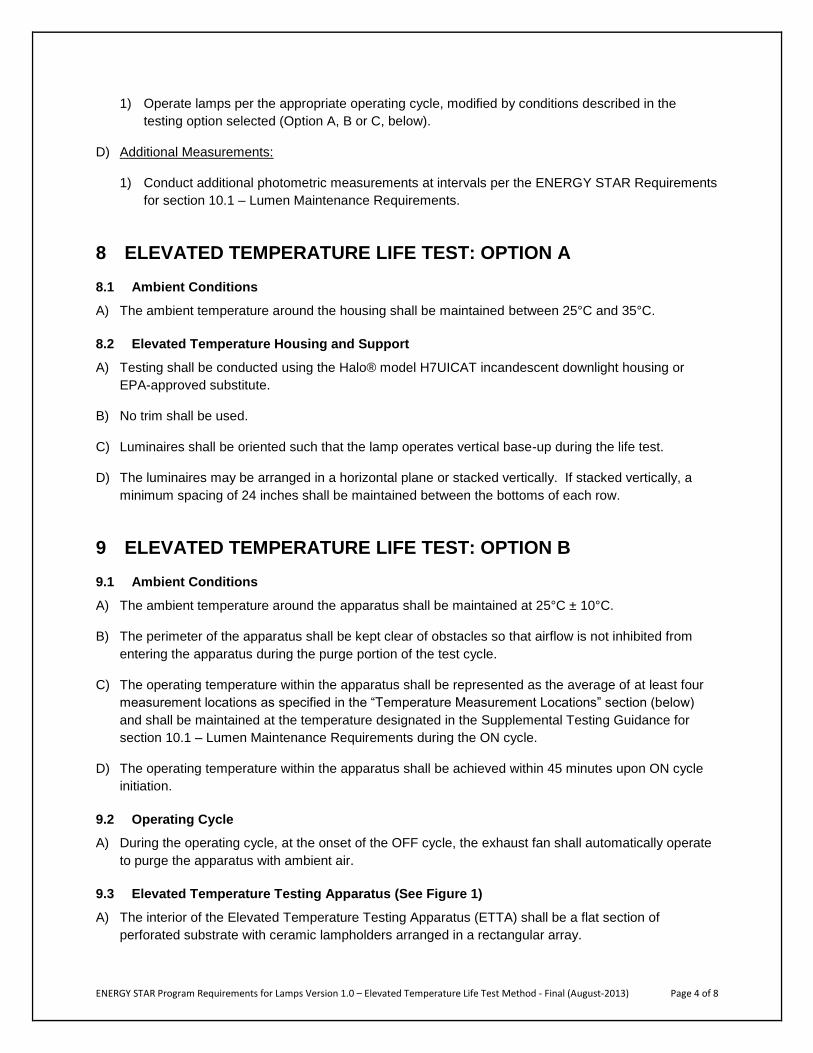
1) Operate lamps per the appropriate operating cycle, modified by conditions described in the
testing option selected (Option A, B or C, below).
D) Additional Measurements:
1) Conduct additional photometric measurements at intervals per the ENERGY STAR Requirements
for section 10.1 – Lumen Maintenance Requirements.
8 ELEVATED TEMPERATURE LIFE TEST: OPTION A
8.1 Ambient Conditions
A) The ambient temperature around the housing shall be maintained between 25°C and 35°C.
8.2 Elevated Temperature Housing and Support
A) Testing shall be conducted using the Halo® model H7UICAT incandescent downlight housing or
EPA-approved substitute.
B) No trim shall be used.
C) Luminaires shall be oriented such that the lamp operates vertical base-up during the life test.
D) The luminaires may be arranged in a horizontal plane or stacked vertically. If stacked vertically, a
minimum spacing of 24 inches shall be maintained between the bottoms of each row.
9 ELEVATED TEMPERATURE LIFE TEST: OPTION B
9.1 Ambient Conditions
A) The ambient temperature around the apparatus shall be maintained at 25°C ± 10°C.
B) The perimeter of the apparatus shall be kept clear of obstacles so that airflow is not inhibited from
entering the apparatus during the purge portion of the test cycle.
C) The operating temperature within the apparatus shall be represented as the average of at least four
measurement locations as specified in the “Temperature Measurement Locations” section (below)
and shall be maintained at the temperature designated in the Supplemental Testing Guidance for
section 10.1 – Lumen Maintenance Requirements during the ON cycle.
D) The operating temperature within the apparatus shall be achieved within 45 minutes upon ON cycle
initiation.
9.2 Operating Cycle
A) During the operating cycle, at the onset of the OFF cycle, the exhaust fan shall automatically operate
to purge the apparatus with ambient air.
9.3 Elevated Temperature Testing Apparatus (See Figure 1)
A) The interior of the Elevated Temperature Testing Apparatus (ETTA) shall be a flat section of
perforated substrate with ceramic lampholders arranged in a rectangular array.

ENERGY STAR Program Requirements for Lamps Version 1.0 – Elevated Temperature Life Test Method - Final (August-2013) Page 5 of 8
B) The perforated substrate shall have holes of a minimum diameter of ¼ inch spaced at a maximum
spacing of 1 inch on center.
C) The spacing between lampholders shall be no less than 8 inches on center and no greater than 12
inches on center.
D) Radiant baffles shall be installed at the mid-point between all lampholders and along the perimeter of
the lampholder array. The radiant baffles shall be constructed of an opaque, rigid material and shall
be a minimum of 10 inches in height.
E) The exterior of the ETTA shall be sealed and insulated to a minimum level of R-13 on all four sides
and the hood.
F) The sides of the apparatus shall extend a minimum of 12 inches below the bottom of the radiant
baffles and shall have an intake section a minimum of 6 inches in height below the sides of the
apparatus.
G) The slope of the hood of the apparatus shall be at least 30° above the horizontal.
H) The top of the hood shall be equipped with an exhaust fan and louver. The fan shall be sized to
deliver a minimum of 4.0 cubic feet per minute (cfm) per square foot of apparatus area net of intake
and exhaust restrictions.
I) The exhaust fan shall be thermostatically controlled to maintain the appropriate ambient temperature
within the apparatus.
J) The louver shall automatically close when the fan is not operating.

ENERGY STAR Program Requirements for Lamps Version 1.0 – Elevated Temperature Life Test Method - Final (August-2013) Page 6 of 8
Figure 1: Option B Elevated Temperature Test Apparatus
9.4 Temperature Measurement Locations
A) The apparatus shall be equipped with at least four ambient temperature measurement devices.
B) These devices shall be placed in at least two locations between 16 and 24 inches measured inwards
from the perimeter of the apparatus and at least two locations between 16 and 24 inches measured
outwards from the center of the apparatus.
C) The operating temperature of the testing area is defined as the average of at least four temperature
readings within the testing area.
D) The measurement points shall be located at the height of the lamps under test.
9.5 Photometric Measurements
There are two methods of photometric measurement, as applicable, for Elevated Temperature Life
Testing Option B.
A) Option B Photometric Measurement Method 1: Applicable to CFLs and omnidirectional LED lamps
only
1) The photometric measurement device shall consist of a securely mounted photodetector
positioned such that the plane of its detector is horizontal. Sufficient shielding shall be
incorporated such that only the light from the lamp under test is measured. This shielding can be
Thermostatically
controlled exhaust
Intake Intake
Temperature per
Specification
25°C ± 10˚C
Insulation
Perforated
substrate
Radiant baffles
Ceramic lampholders
Temperature
sensors
25°C ± 10˚C
ENERGY STAR Program Requirements for Lamps Version 1.0 – Elevated Temperature Life Test Method - Final (August-2013) Page 7 of 8
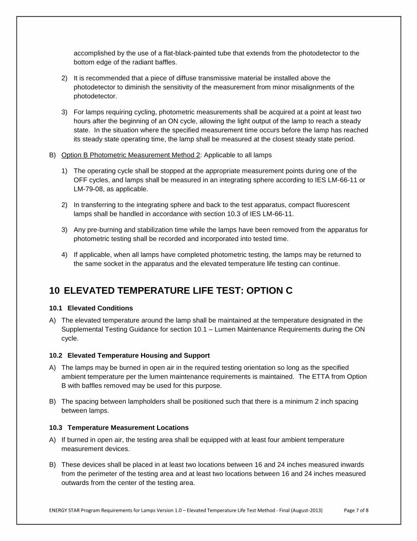
accomplished by the use of a flat-black-painted tube that extends from the photodetector to the
bottom edge of the radiant baffles.
2) It is recommended that a piece of diffuse transmissive material be installed above the
photodetector to diminish the sensitivity of the measurement from minor misalignments of the
photodetector.
3) For lamps requiring cycling, photometric measurements shall be acquired at a point at least two
hours after the beginning of an ON cycle, allowing the light output of the lamp to reach a steady
state. In the situation where the specified measurement time occurs before the lamp has reached
its steady state operating time, the lamp shall be measured at the closest steady state period.
B) Option B Photometric Measurement Method 2: Applicable to all lamps
1) The operating cycle shall be stopped at the appropriate measurement points during one of the
OFF cycles, and lamps shall be measured in an integrating sphere according to IES LM-66-11 or
LM-79-08, as applicable.
2) In transferring to the integrating sphere and back to the test apparatus, compact fluorescent
lamps shall be handled in accordance with section 10.3 of IES LM-66-11.
3) Any pre-burning and stabilization time while the lamps have been removed from the apparatus for
photometric testing shall be recorded and incorporated into tested time.
4) If applicable, when all lamps have completed photometric testing, the lamps may be returned to
the same socket in the apparatus and the elevated temperature life testing can continue.
10 ELEVATED TEMPERATURE LIFE TEST: OPTION C
10.1 Elevated Conditions
A) The elevated temperature around the lamp shall be maintained at the temperature designated in the
Supplemental Testing Guidance for section 10.1 – Lumen Maintenance Requirements during the ON
cycle.
10.2 Elevated Temperature Housing and Support
A) The lamps may be burned in open air in the required testing orientation so long as the specified
ambient temperature per the lumen maintenance requirements is maintained. The ETTA from Option
B with baffles removed may be used for this purpose.
B) The spacing between lampholders shall be positioned such that there is a minimum 2 inch spacing
between lamps.
10.3 Temperature Measurement Locations
A) If burned in open air, the testing area shall be equipped with at least four ambient temperature
measurement devices.
B) These devices shall be placed in at least two locations between 16 and 24 inches measured inwards
from the perimeter of the testing area and at least two locations between 16 and 24 inches measured
outwards from the center of the testing area.

ENERGY STAR Program Requirements for Lamps Version 1.0 – Elevated Temperature Life Test Method - Final (August-2013) Page 8 of 8
C) The operating temperature of the testing area is defined as the average of at least four temperature
readings within the testing area.
D) The measurement point shall be located at the height of the lamps under test.
11 TEST REPORT ETLT report data may be included in an overall performance report or a stand alone report, and shall
include the following test information:
A) Manufacturer’s name and product identification
B) Name and location of testing facility
C) Name of person(s) performing the test
D) Test dates
E) Elevated Temperature Life Testing Option used
F) Operating (Elevated) temperature
G) Lamp operating orientation
H) Operating duration
I) Photometric and electrical measurements at the appropriate intervals
J) As applicable, number of hours of operation before failure or note that the lamp reached rated life
K) Notes describing any non-lumen maintenance failure (e.g. envelope failure, broken glass, cracking,
failed LEDs or excessive discoloration) of any lamp that completes testing.
ENERGY STAR Program Requirements for Lamps Version 1.0 – Elevated Temperature Light Output Ratio Test Method - Final (August-2013) Page 1 of 4
ENERGY STAR® Program Requirements
Product Specification for Lamps Version 1.0:
Elevated Temperature Light Output Ratio
Test Method
August-2013
1 OVERVIEW The following test method shall be used for determining product compliance with the Elevated
Temperature Light Output Ratio (ETLOR) requirements in the ENERGY STAR Eligibility Criteria for
Lamps. Two measurement methods, contrasting the light output of lamps in restricted airflow luminaires
to the light output of lamps in an ambient temperature environment, are provided.
2 APPLICABILITY ENERGY STAR test requirements are dependent upon the product technology and lamp category of the
product under evaluation. The following guidelines shall be used to determine the applicability of each
section of this document:
The ETLOR applies to directional lamps; see the Eligibility Criteria for Lamps for applicable
exemptions.
The test procedures in Section 7 shall be performed on products that are required to undergo the
Elevated Temperature Light Output Ratio test.
3 DEFINITIONS Unless otherwise specified, all terms used in this document are consistent with the definitions in the
ENERGY STAR Eligibility Criteria for Lamps.
4 METHODS OF MEASUREMENT AND REFERENCE DOCUMENTS
4.1 IES Test Methods and Reference Documents
A) IES LM-65-10. 2010. IES Approved Method for Life Testing of Compact Fluorescent Lamps,
Illuminating Engineering Society, New York.
B) IES LM-66-11. 2011. IES Approved Method for Electrical and Photometric Measurements of
Single-Ended Compact Fluorescent Lamps, Illuminating Engineering Society, New York.
C) IES LM-79-08. 2008. IES Approved Method for Electrical and Photometric Measurements of Solid-
State Lighting Products, Illuminating Engineering Society, New York.
D) IES LM-78-07. 2007 IES Approved Method for Total Luminous Flux Measurement of Lamps Using
an Integrating Sphere Photometer, Illuminating Engineering Society, New York.

ENERGY STAR Program Requirements for Lamps Version 1.0 – Elevated Temperature Light Output Ratio Test Method - Final (August-2013) Page 2 of 4
E) IES LM-54-12. 2012. IES Guide to Lamp Seasoning, Illuminating Engineering Society, New York.
F) IES LM-28-12. 2012. Guide for the Selection, Care, and Use of Electrical Instruments in the
Photometric Laboratory, Illuminating Engineering Society, New York.
5 TEST SETUP
5.1 General
A) Test Setup and Instrumentation: Test setup and instrumentation for the lamp operation portions of
this procedure shall be in accordance with the requirements of IES LM-65-10, unless otherwise noted
in this document. In the event of conflicting requirements, the ENERGY STAR test method shall take
precedence.
B) Lamp Seasoning and Preburning: Prior to the first readings, compact fluorescent lamps (CFLs) shall
be seasoned for 100 hours in accordance with IES-LM-54-12. CFLs shall be preburned in accordance
with IES LM-66-11. CFLs shall be seasoned and preburned in the position that the lamps will undergo
the ETLOR test. Seasoning shall be accomplished outside of any elevated temperature testing
environment. LED lamps shall not be seasoned.
C) Input Power for Photometric Measurements: During the stabilization and photometric testing of
products intended to be powered from AC mains, the product shall be connected to a voltage source
that meets the requirements in IES LM-66-11 or IES LM-79-08 as applicable. When selecting a
power supply for use with integrated lamps, it is necessary to apply the appropriate power factor
when specifying the volt-amp capacity of the power supply.
D) Ambient Temperature: Ambient temperature shall be as stated in the specification for the duration of
the test. Temperature measurements shall be taken using a temperature measurement device
consisting of a thermocouple junction or resistance temperature detector (RTD) probe combined with
an appropriate meter. Thermocouples or probes shall be chosen to ensure accuracy within the test
temperature range.
E) Power Meter: Power meters shall be capable of measuring to the appropriate metrics of IES LM-66-
11 or IES LM-79-08 as applicable.
F) Environmental Conditions: The test environment shall be clean and free from large amounts of dust
and moisture.
G) Sample Selection: Samples shall be representative of the manufacturer’s typical product. The
samples shall be clean and thoroughly inspected before testing. Any flaws or inconsistencies in the
lamp samples shall be noted.
5.2 Elevated Temperature Measurement: Measurement in a Thermal Chamber
A) For the thermal chamber, utilize the Elevated Temperature Housing and Support outlined in the
ENERGY STAR Program Requirements Product Specification for Lamps: Elevated Temperature Life
Testing, Option A or Option B. Refer to sections 8 and 9 of the Elevated Temperature Life Test for
specific details.
B) Ambient air temperature measurements shall be taken at a location 1inch below the base (defined as
the lowest point on the metal Edison socket when installed in a base-up position) of the lamp and 2

ENERGY STAR Program Requirements for Lamps Version 1.0 – Elevated Temperature Light Output Ratio Test Method - Final (August-2013) Page 3 of 4
inches from the base of the lamp toward the enclosure wall. Measurement points should be no more
than one meter from the lamp in accordance to IES LM-66-11 or IES LM-79-08.
C) A controlled draft enclosure shall be used to limit air movement across the lamp to a maximum of
0.08 m/s (15.7 ft/min) when placed in the thermal chamber.
D) The photometric measurement device shall consist of a securely mounted photodetector positioned
such that the plane of its detector is horizontal. Sufficient shielding shall be incorporated such that
only the light from the lamp under test is measured. This shielding can be accomplished by the use
of a flat-black-painted tube that extends from the photodetector to the base of the lamp. Additionally,
it is recommended that a piece of diffuse transmissive material be installed above the photodetector
to diminish the sensitivity of the measurement from minor misalignments of the photodetector.
5.3 Elevated Temperature Measurement: Measurement in an Integrating Sphere
A) A 4π sphere or a 2π sphere may be used.
B) For 2π geometry integrating sphere systems in which the lamp is external to the sphere, a thermal
chamber around the lamp may be used to achieve the elevated ambient temperature without
elevating the temperature of the sphere. The thermal chamber may be in accordance with the
Elevated Temperature Housing and Support section 8.2 for Option A in the ENERGY STAR Elevated
Temperature Life Test.
C) Integrating sphere or thermal chamber shall limit air movement across the lamp, using the method
described in IES LM-66-11 section 5.3.
6 TEST CONDUCT
6.1 Guidance for Elevated Temperature Light Output Ratio
D) Photometric Measurements:
1) For integrating sphere measurements, refer to IES LM-66-11 or IES-LM-79-08 as applicable.
2) For non-integrating sphere measurements, the photodetector used for photometric
measurements shall be a silicon detector corrected to closely fit the Commission Internationale
de l’Eclairage (CIE) spectral luminous efficiency curve (V ).
E) Lamp Stabilization for All lamps, Transfer and Re-stabilizations for CFLs:
1) Stabilize lamps per IES LM-66-11 or LM-79-08 as applicable.
2) CFLs to be removed from the seasoning area for ETLOR testing shall be handled according to
IES LM-66-11.

ENERGY STAR Program Requirements for Lamps Version 1.0 – Elevated Temperature Light Output Ratio Test Method - Final (August-2013) Page 4 of 4
7 TEST PROCEDURES
7.1 General Test Procedure
A) Lamp Installation
1) Install the lamp in the thermally controlled environment or thermal chamber.
B) Initial Measurement:
1) Apply the rated lamp voltage while operating in a thermally controlled environment such that the
temperature at the apparatus or integrating sphere test point is stable as determined by three
measurements, 5 minutes apart at ambient temperature per the specification, and the three
measurements not varying by more than ±1°C.
2) Achieve lamp light output stabilization per the “Lamp Stabilization for All lamps, Transfer and Re-
stabilizations for CFLs” section, described above. Lamp stabilization may be concurrent with
temperature stabilization.
3) Measure and record light output, input electrical values and test point temperature.
C) Elevated Temperature Measurement
1) Apply the rated lamp voltage while operating in a thermally controlled environment such that the
temperature at the test point is stable per IES LM-66-11 or IES LM-79-08, as applicable.
2) Conduct measurement of each lamp following the procedures set forth in IES LM-66-11 or IES
LM-79-08, as applicable, with the exception of the elevated temperature.
8 TEST REPORT ETLOR report data may be included in an overall performance report or a stand alone report, and shall
include the following test information:
A) Manufacturer’s name and product identification
B) Name and location of the testing facility
C) Test date
D) Lamp base orientation
E) Elevated temperature light output measurement method used
F) Electrical, photometric, and temperature values at the ambient condition
G) Electrical, photometric, and temperature values at the elevated temperature condition
H) Elevated Temperature Light Output Ratio, calculated as the light output at the elevated temperature
condition divided by the light output at the ambient condition, expressed as a percentage

ENERGY STAR Program Requirements for Lamps Version 1.0 – Start Time Test Method - Final (August-2013) Page 1 of 5
ENERGY STAR® Program Requirements
Product Specification for Lamps Version 1.0:
Start Time
Test Method
August-2013
1 OVERVIEW The following test method shall be used for determining product compliance with start time requirements
in the ENERGY STAR Eligibility Criteria for Lamps.
2 APPLICABILITY
ENERGY STAR test requirements are dependent upon the product category of the product under
evaluation. The following guidelines shall be used to determine the applicability of each section of this
document:
The start time test method applies to all compact fluorescent lamps (CFLs) and solid state lighting
(SSL) lamps included in the specification.
The test procedures in Section 7 shall be performed on products that are required to undergo the
ENERGY STAR Start Time Test.
3 DEFINITIONS
Unless otherwise specified, all terms used in this document are consistent with the definitions in the
ENERGY STAR Eligibility Criteria for Lamps.
Start Time: The time between the application of power to the device and the point where light output
reaches 98% of the lamp’s initial plateau.
Initial Plateau: The point at which the average increase in the light output over time levels out (reduces in
slope). This can be determined mathematically or visually based on the lamp output trace. For
examples, see section 9.
4 METHODS OF MEASUREMENT AND REFERENCE DOCUMENTS
4.1 IES Test Methods and Reference Documents
A) IES LM-66-11: 2011. IES Approved Method for Electrical and Photometric Measurements of Single-
Ended Compact Fluorescent Lamps, Illuminating Engineering Society, New York.
B) IES LM-79-08: 2008. IES Approved Method for Electrical and Photometric Measurements of Solid-
State Lighting Products, Illuminating Engineering Society, New York.
C) IES LM-54-12: 2012. IES Guide to Lamp Seasoning, Illuminating Engineering Society, New York.

ENERGY STAR Program Requirements for Lamps Version 1.0 – Start Time Test Method - Final (August-2013) Page 2 of 5
5 TEST SETUP
5.1 General
A) Test Setup and Instrumentation:
1) Regulated AC or DC power supply (as applicable to the lamp)
2) Multichannel oscilloscope with data storage capability
3) Appropriate attenuator probe(s)
4) Photodetector
B) Lamp Seasoning and Preburning: Prior to the first readings, compact fluorescent lamps (CFL) shall
be seasoned for 100 hours in accordance with IES LM-54-12. CFLs shall be preburned in accordance
with IES LM-66-11. LED lamps shall not be seasoned.
C) Input Power for Start Time Measurements: The power requirements shall be per IES LM-66-11 or
LM-79-08 as applicable. When selecting a power supply for use with integrated lamps, it is
necessary to apply an appropriate power factor when specifying the Volt-Amp capacity of the power
supply.
D) Lamp Storage: Lamps shall be stored at 25°C ± 5°C for a minimum of 16 hours prior to the test, after
which the temperature range shall be 25°C ± 1°C for at least two hours immediately prior to the test.
CFL samples shall be off for 20 hours ± 4 hours prior to the test. If the CFL sample has been off
more than 24 hours, it shall be operated for 3 hours and then turned off for 20 hours ± 4 hours prior to
conducting the test.
E) Ambient Temperature: Testing shall take place in an ambient temperature of 25°C ± 1°C. Drafts shall
be minimized.
F) Power Meter: Power meters shall be capable of measuring to the appropriate requirements of IES
LM-66-11 or IES LM-79-08 as applicable.
G) Environmental Conditions: The test environment shall be clean and free from large amounts of dust
and moisture.
H) Orientation: Test samples in orientation(s) as specified by the ENERGY STAR specification or
manufacturer specified position if different.
I) Sample Selection: Samples shall be representative of the manufacturer’s typical product. The
samples shall be clean and thoroughly inspected before testing. Any flaws or inconsistencies in the
lamp samples shall be noted.
6 TEST CONDUCT
6.1 Guidance for Implementation of Start Time Test Procedure
A) Photometric Measurements:
1) For integrating sphere measurements, refer to IES LM-66-11 or IES-LM-79-08 as applicable.
2) For non-integrating sphere measurements, the photodetector used for photometric
measurements shall be a silicon detector corrected to closely fit the Commission Internationale
de l’Eclairage (CIE) spectral luminous efficiency curve (V ).

ENERGY STAR Program Requirements for Lamps Version 1.0 – Start Time Test Method - Final (August-2013) Page 3 of 5
B) Lamp Transfer for CFLs:
1) CFLs shall be stored per requirements in the Environmental Conditions section before being
transported to the start time testing equipment. Care shall be exercised to maintain lamp
orientation and avoid shaking or bumping the lamp during the transfer from seasoning.
7 TEST PROCEDURE
7.1 General Test Procedure
A) Install the lamp in the test environment.
B) For non-integrating sphere measurements, position the photocell so it sees the main body of the
discharge tube or array (as applicable). Shield from extraneous light as needed.
For integrating sphere measurements, see test conduct section 6.1.A.1
C) When testing a covered CFL, the photocell only needs to see the outer luminous face of the sample.
D) Connect oscilloscope probe to measure the input voltage to the sample, and light output.
E) Set the scope to trigger off the input voltage signal. Set trigger level at 10V.
F) Set power supply to rated voltage and frequency of the device. If a range is specified, test sample at
the midpoint of the range.
G) Use an exemplar sample to determine the proper voltage and time base settings. Suggested initial
time base is 200 mS/div.
H) Apply rated voltage/frequency to the device.
I) Record the input voltage and light output waveform on which the starting time was based.
J) Record starting time based on 98% of initial plateau of light output. See Examples 1 and 2 below.
8 TEST REPORT
Start Time test report data shall include the following test information:
A) Manufacturer’s name and product identification
B) Name and location of testing facility
C) Test date
D) Lamp base orientation
E) Test voltage (V)
F) Test frequency (Hz)
G) Time base setting (mS/div)
H) Input voltage and light output waveforms on which the starting time is based
I) Starting time (mS)

ENERGY STAR Program Requirements for Lamps Version 1.0 – Start Time Test Method - Final (August-2013) Page 4 of 5
9 EXAMPLES:
9.1 Example 1 – Compact Fluorescent Lamp
Purple Trace – Input Voltage
Green Trace – Lamp Arc Voltage
Blue Trace – Light Output
Initial Plateau Start Time (18ms) at
98% of Initial Plateau

ENERGY STAR Program Requirements for Lamps Version 1.0 – Start Time Test Method - Final (August-2013) Page 5 of 5
9.2 Example 2 – LED Lamp
Starting Time (62.4 ms)
at 98% of Initial Plateau
Initial Plateau
Blue Trace – Light Output
Purple Trace – Input Voltage

ENERGY STAR Program Requirements for Lamps Version 1.0 – Run-Up Time Test Method - Final (August-2013) Page 1 of 3
ENERGY STAR® Program Requirements
Product Specification for Lamps Version 1.0:
Run-Up Time
Test Method
August-2013
1 OVERVIEW The following test method shall be used for determining product compliance with run-up time
requirements in the ENERGY STAR Eligibility Criteria for Lamps.
2 APPLICABILITY
ENERGY STAR test requirements are dependent upon the product technology and lamp category of the
product under evaluation. The following guidelines shall be used to determine the applicability of each
section of this document:
The run-up time test method applies to all CFLs included in the specification.
The test procedures in Section 7 shall be performed on products that are required to undergo the
ENERGY STAR Run Up Test.
3 DEFINITIONS
Unless otherwise specified, all terms used in this document are consistent with the definitions in the
ENERGY STAR Eligibility Criteria for Lamps.
Run-Up Time: The time between the application of power to the device and the time when the light
output first reaches a specified percentage of stable light output, e.g., t80%, t90%, etc.
4 METHODS OF MEASUREMENT AND REFERENCE DOCUMENTS
4.1 IES Test Methods and Reference Documents
A) IES LM-66-11: 2011. IES Approved Method for Electrical and Photometric Measurements of Single-
Ended Compact Fluorescent Lamps, Illuminating Engineering Society, New York.
B) IES LM-54-12: 2012. IES Guide to Lamp Seasoning, Illuminating Engineering Society, New York.
5 TEST SETUP
5.1 General
A) Test Setup and Instrumentation:

ENERGY STAR Program Requirements for Lamps Version 1.0 – Run-Up Time Test Method - Final (August-2013) Page 2 of 3
1) Regulated AC or DC power supply (as applicable to the lamp)
2) Integrating sphere, cube, or similar device and associated equipment
3) Means of recording light output vs. time (i.e., computer sampling or digital recorder) in one
second intervals or less such as an oscilloscope or photometer
4) Photodetector
B) Lamp Seasoning and Preburning: Prior to the first readings, compact fluorescent lamps (CFL) shall
be seasoned for 100 hours in accordance with IES LM-54-12. CFLs shall be preburned in accordance
with IES LM-66-11.
C) Input Power for Run Up Measurements: The power requirements shall be per IES LM-66-11. When
selecting a power supply for use with integrated lamps, it is necessary to apply an appropriate power
factor when specifying the Volt-Amp capacity of the power supply.
D) Lamp Storage: After seasoning (as applicable), lamps shall be stored at 25°C ± 1°C for a minimum of
16 hours prior to the test. CFL samples shall be off for 20 hours ± 4 hours prior to the test. If the
sample has been off more than 24 hours, it shall be operated for 3 hours and then turned off for 20
hours ± 4 hours prior to testing.
E) Ambient Temperature: Testing shall take place in an ambient temperature of 25°C ± 1°C. Drafts shall
be minimized.
F) Power Meter: Power meters shall be capable of measuring to the appropriate requirements of IES
LM-66-11.
G) Environmental Conditions: The test environment shall be clean and free from large amounts of dust
and moisture.
H) Orientation: Test samples in orientation(s) as specified by the ENERGY STAR specification or
manufacturer specified position if different.
I) Sample Selection: Samples shall be representative of the manufacturer’s typical product. The
samples shall be clean and thoroughly inspected before testing. Any flaws or inconsistencies in the
lamp samples shall be noted.
6 TEST CONDUCT
6.1 Guidance for Implementation of Run Up Test Procedure
A) Photometric Measurements:
1) For integrating sphere measurements, refer to IES LM-66-11.
2) For non-integrating sphere measurements, the photodetector used for photometric
measurements shall be a silicon detector corrected to closely fit the Commission Internationale
de l’Eclairage (CIE) spectral luminous efficiency curve (V ).
B) Lamp Transfer and Stabilizations for CFLs:
1) CFLs shall be stored per requirements in the Environmental Conditions section before being
transported to the run up testing equipment. Care shall be exercised to maintain lamp orientation
and avoid shaking or bumping the lamp during the transfer from seasoning. All lamps shall be
stabilized per IES LM-66-11.

ENERGY STAR Program Requirements for Lamps Version 1.0 – Run-Up Time Test Method - Final (August-2013) Page 3 of 3
7 TEST PROCEDURES
7.1 General Test Procedures
A) Test samples in orientation(s) as specified by the ENERGY STAR specification or manufacturer
specified position if different or restricted.
B) Set power supply to rated voltage and frequency of the device. If a range is specified, test sample at
the midpoint of the range.
C) Randomly select sample from available lamps.
7.2 Test Procedure Method
For a relative measurement, the test chamber does not need to be an integrating sphere, and may be
something less sophisticated such as a cube or other shaped chamber. For an absolute measurement of
luminous flux over time, an integrating sphere is required.
A) Place lamp in integrating sphere, cube, dodecahedron, or similar device that eliminates extraneous
light.
B) Apply rated voltage/frequency to the device.
C) Record light output reading in no greater than one second intervals until the light output has
stabilized.
D) Record full stabilization time and value.
E) Determine desired run-up characteristic, e.g., t80%, t90%, etc. from the data.
8 TEST REPORT
Run-Up Time Test report data may be included in an overall performance report or a standalone report,
and shall include the following test information: Manufacturer’s name and product identification
A) Name and location of testing facility
B) Test date
C) Lamp base orientation
D) Test voltage (V)
E) Test frequency (Hz)
F) Percentage of stable light output tested to
G) Waveform on which the run up time is based
H) Stabilized light output
I) Stabilization time
J) Run-up light output
K) Run-up time (S)

ENERGY STAR Program Requirements for Lamps Version 1.0 – Light Output on a Dimmer Recommended Practice – Final (August-2013)Page 1 of 5
ENERGY STAR® Program Requirements
Product Specification for Lamps Version 1.0:
Light Output on a Dimmer
Recommended Practice
August-2013
1 OVERVIEW This document provides the recommended practice for determining the maximum and minimum light
output on a dimmer. This procedure can be performed concurrently with the ENERGY STAR Flicker
testing.
2 APPLICABILITY The following guidelines shall be used to determine the applicability of each section of this document:
The test method applies to all compact fluorescent lamps (CFLs) and solid state lighting (SSL)
lamps covered in the scope of the ENERGY STAR Eligibility Criteria for Lamps that are marketed
as dimmable.
3 DEFINITIONS Unless otherwise specified, all terms used in this document are consistent with the definitions in the
ENERGY STAR Eligibility Criteria for Lamps.
Baseline Light Output: The baseline light output (BLO) refers to the stabilized light output of the unit
under test (UUT) operating without a dimmer in the circuit.
Maximum Control Position: The setting on the dimmer or control device intended to achieve the
maximum light output during operation.
Maximum Light Output: The maximum light output (MaxLO) refers to the light output of the lamp when
operating with a dimmer in the circuit at the Maximum Control Position.
Maximum Light Output Ratio: The maximum light output ratio (MaxLOR) refers to the ratio of the
maximum light output (MaxLO) to the Baseline Light Output (BLO). Light output may be absolute or
relative measurements.
Minimum Dimming Level Claimed: The minimum light output level of a lamp when operated with a
dimmer in the circuit, as declared by the lamp manufacturer. Typically expressed as a percentage.
Minimum Light Output: The minimum light output (MinLO) refers to the minimum light output when the
lamp is operating with a dimmer in the circuit.
Minimum Light Output Ratio: The minimum light output ratio (MinLOR) refers to the ratio of the
minimum light output (MinLO) to the maximum light output (MaxLO). .

ENERGY STAR Program Requirements for Lamps Version 1.0 – Light Output on a Dimmer Recommended Practice – Final (August-2013)Page 2 of 5
Unit Under Test: The unit under test (UUT) refers the the specific lamp sample being tested.
4 METHODS OF MEASUREMENT AND REFERENCE DOCUMENTS
4.1 IES Test Methods and Reference Documents
A) IES LM-66-11: 2011. IES Approved Method for Electrical and Photometric Measurements of Single-
Ended Compact Fluorescent Lamps, Illuminating Engineering Society, New York.
B) IES LM-79-08: 2008. IES Approved Method for Electrical and Photometric Measurements of Solid-
State Lighting Products, Illuminating Engineering Society, New York.
C) IES LM-54-12: 2012. IES Guide to Lamp Seasoning, Illuminating Engineering Society, New York.
5 TEST SETUP
5.1 General
A) Test Setup and Instrumentation: The test can be performed using an absolute photometry method or
a relative photometry method, and the equipment required depends on the method used.
1) Equipment required for absolute photometry measurement:
a) Power supply and meter that complies with IES LM-79-08 or IES LM-66-11 as applicable.
See 5.1.C and 5.1.E.
b) Photometer or similar equipment for comparing output readings from a photodetector
c) Photodetector
d) Integrating sphere
2) Equipment required for relative photometry measurement:
a) Power supply and meter that complies with IES LM-79-08 or IES LM-66-11 as applicable.
See 5.1.C and 5.1.E.
b) Photodetector capable of measuring relative light output
c) Method of ensuring the light measured comes only from the UUT.
B) Lamp Seasoning and Preburning: Prior to the first readings, compact fluorescent lamps (CFLs) shall
be seasoned for 100 hours in accordance with IES LM-54-12. CFLs shall be preburned in accordance
with IES LM-66-11. LED lamps shall not be seasoned.
C) Input Power for Measurements: The power requirements shall be per IES LM-66-11 or LM-79-08 as
applicable. Note: When selecting a power supply for use with integrated lamps, it is necessary to
apply an appropriate power factor when specifying the Volt-Amp rating of the power supply.
D) Ambient Temperature: Lamp testing shall take place in an ambient temperature of 25°C ± 5°C. Drafts
shall be minimized.

ENERGY STAR Program Requirements for Lamps Version 1.0 – Light Output on a Dimmer Recommended Practice – Final (August-2013)Page 3 of 5
E) Power Meter: Power meters shall be capable of measuring to the appropriate requirements of IES
LM-66-11 or IES LM-79-08 as applicable. Any power measurements should measure the power of
the lamp under test, and not the dimmer.
F) Environmental Conditions: The test environment shall be clean and free from large amounts of dust
and moisture.
G) Sample Selection: Samples shall be representative of the manufacturer’s typical product. The
samples shall be clean and thoroughly inspected before testing. Any flaws or inconsistencies in the
lamp samples shall be noted. The sample(s) used for light output on a dimmer testing shall be the
same sample(s) used for the ENERGY STAR Flicker testing, if applicable, and can be the same
sample(s) used for other testing.
6 TEST CONDUCT
6.1 Guidance for Implementation Maximum Light Output on a Dimmer Test Procedure
A) Photometric Measurements:
1) For absolute (integrating sphere) measurements, refer to IES LM-66-11 or IES-LM-79-08 as
applicable with the exception of the guidance for lamp stabilization.
2) For relative (non-integrating sphere) measurements, the photodetector used for photometric
measurements shall be a silicon detector corrected to closely fit the Commission Internationale
de l’Eclairage (CIE) spectral luminous efficiency curve (V ).
a) Ensure that the measurement equipment receives the appropriate voltage range from the
photodetector, using an amplifier if necessary.
b) The UUT and the photometer shall not be moved during testing.
B) Lamp Transfer for CFLs:
1) Care shall be exercised to maintain lamp orientation and avoid shaking or bumping the lamp
during the transfer from seasoning area.
C) Low Voltage Lamps
1) Lamps designed for operation on low voltage transformers shall be operated on a compatible
transformer specified or supplied by the lamp manufacturer.
2) Electrical measurements shall include characteristics of the lamp.
D) Measurements:
1) The following data shall be collected at each measurement point:
a) Light output
b) Power consumption
c) Power factor

ENERGY STAR Program Requirements for Lamps Version 1.0 – Light Output on a Dimmer Recommended Practice – Final (August-2013)Page 4 of 5
d) Total harmonic distortion
7 TEST PROCEDURES FOR LAMPS CLAIMING DIMMABILITY
7.1 Test Procedure for Lamp Baseline output
A) Install the lamp in the test environment without a dimmer in the circuit.
B) Set power supply to rated voltage and frequency of the device. If a range is specified, test sample at
the midpoint of the range.
C) Apply rated voltage/frequency to the device.
D) Allow lamp to stabilize per IES LM-66-11 or IES-LM-79-08 as applicable. If lamp has been stabilized
for measurements previously and the stabilization time recorded, the lamp may be considered
stabilized after operating for this period of time.
E) Record readings per Clause 6.1.D.1 from measurement equipment; these are the measurements at
the Baseline Light Output (BLO).
F) Remove power from lamp
7.2 Test Procedures for Lamp Dimmability
A) Install dimmer into the lamp test circuit
B) Apply rated voltage/frequency to the dimmer or control device.
C) Adjust dimmer to the maximum control position.
D) Allow lamp to stabilize and verify by taking light output measurements every minute until consecutive
measurements are no more than 0.5% apart, utilizing previously recorded lamp stabilization time or
verify by mathematical means that the lamp is stabilized.
E) Record readings per Clause 6.1.D.1 from measurement equipment. These are the measurements at
the MaxLO.
F) Adjust dimmer so that the light output is of the lower of:
1) (20% of the MaxLO) ± 5%.
2) (The minimum dimming level claimed as a percentage of the MaxLO) ± 5%
For example: A lamp with a MaxLO of 1000 lumens and a minimum claimed dimming level of
20% should be adjusted to a light output level that is between 190 and 210 lumens.
G) Allow lamp to stabilize and verify by taking light output measurements every minute, until consecutive
measurements are no more than 0.5% apart, utilizing previously recorded lamp stabilization time or
verify by mathematical means that the lamp is stabilized.
H) Verify that the lamp light output is still within the range in F)
1) If not, repeat step F) and G)

ENERGY STAR Program Requirements for Lamps Version 1.0 – Light Output on a Dimmer Recommended Practice – Final (August-2013)Page 5 of 5
2) If light output is within range, record readings from measurement equipment per Clause 6.1.D.1.
These are the measurements at the MinLO.
I) Repeat steps 7.2A-H for each dimmer to be tested. A test setup that includes a device that allows hot
switching between dimmers may be utilized to bypass stabilization time.
J) Repeat steps 7.2A-H for each dimmer to be tested with 4 lamps on the dimmer circuit, taking
measurements from one lamp.
8 TEST REPORT Maximum and Minimum Light Output on a Dimmer report data shall include the following test information
and be submitted on the ENERGY STAR Dimming Data Sheet:
A) Manufacturer’s name and product identification
B) Name and location of testing facility
C) Test date
D) Lamp base orientation
E) Test voltage (V)
F) Test frequency (Hz)
G) Light output and power consumption at BLO
H) Electrical and photometric test data at the MaxLO for 1 and 4 lamp configurations for each dimmer
tested
I) Electrical and photometric test data at the MinLO for 1 and 4 lamp configurations for each dimmer
tested
J) Stabilization time and stabilization method used
K) Average MaxLOR
L) Average MinLOR

ENERGY STAR Program Requirements for Lamps Version 1.0 – Flicker Recommended Practice – Final (August-2013) Page 1 of 6
ENERGY STAR® Program Requirements
Product Specification for Lamps Version 1.0:
Light Source Flicker
Recommended Practice
August-2013
1 OVERVIEW This document provides the recommended practice for evaluating flicker with and without a dimmer. This
test can be performed concurrently with the ENERGY STAR Light Output on a Dimmer testing.
2 APPLICABILITY The following guidelines shall be used to determine the applicability of each section of this document:
This recommended practice applies to all CFL and solid state lighting (SSL) lamps covered in the
scope of the Lamps specification that are marketed as dimmable.
3 DEFINITIONS Unless otherwise specified, all terms used in this document are consistent with the definitions in the
ENERGY STAR Eligibility Criteria for Lamps.
Baseline Light Output: The baseline light output (BLO) refers to the stabilized light output of the unit
under test (UUT) operating without a dimmer in the circuit.
Maximum Control Position: The setting on the dimmer or control device intended to achieve the
maximum light output during operation.
Maximum Light Output: The maximum light output (MaxLO) refers to the light output of the lamp when
operating with a dimmer in the circuit at the Maximum Control Position.
Minimum Dimming Level Claimed: The minimum light output level of a lamp when operated with a
dimmer in the circuit, as declared by the lamp manufacturer. Typically expressed as a percentage.
Minimum Light Output: The minimum light output (MinLO) refers to the minimum light output when the
lamp is operating with a dimmer in the circuit.
Unit Under Test: The unit under test (UUT) refers the the specific lamp sample being tested.

ENERGY STAR Program Requirements for Lamps Version 1.0 – Flicker Recommended Practice – Final (August-2013) Page 2 of 6
4 METHODS OF MEASUREMENT AND REFERENCE DOCUMENTS
4.1 IES Test Methods and Reference Documents
A) IES LM-66-11: 2011. IES Approved Method for Electrical and Photometric Measurements of Single-
Ended Compact Fluorescent Lamps, Illuminating Engineering Society, New York.
B) IES LM-79-08: 2008. IES Approved Method for Electrical and Photometric Measurements of Solid-
State Lighting Products, Illuminating Engineering Society, New York.
C) IES LM-54-12: 2012. IES Guide to Lamp Seasoning, Illuminating Engineering Society, New York.
D) IES RP-16-10: 2010. IES Nomenclature and Definitions for Illuminating Engineering, Illuminating
Engineering Society, New York.
5 TEST SETUP
5.1 General
A) Test Setup and Instrumentation: The test can be performed using an absolute photometry method or
a relative photometry method, and the equipment required depends on the method used.
1) Equipment required for absolute photometry measurement:
a) Power supply and meter that complies with IES LM-79-08 or IES LM-66-11 as applicable.
See 5.1.C and 5.1.E.
b) Multichannel oscilloscope with data storage capability or similar equipment for comparing
output readings from a photodetector
c) Appropriate attenuator probe(s), if applicable
d) Photodetector
e) Integrating sphere
2) Equipment required for relative photometry measurement:
a) Power supply and meter that complies with IES LM-79-08 or IES LM-66-11 as applicable.
See 5.1.C and 5.1.E.
b) Multichannel oscilloscope with data storage capability or similar equipment for comparing
output readings from a photodetector
c) Appropriate attenuator probe(s), if applicable
d) Photodetector capable of measuring relative light output
e) Method of ensuring the light measured comes only from the UUT.
B) Lamp Seasoning and Preburning: Prior to the first readings, compact fluorescent lamps (CFLs) shall
be seasoned for 100 hours in accordance with IES LM-54-12. CFLs shall be preburned in accordance
with IES LM-66-11. LED lamps shall not be seasoned.

ENERGY STAR Program Requirements for Lamps Version 1.0 – Flicker Recommended Practice – Final (August-2013) Page 3 of 6
C) Input Power for Measurements: The power requirements shall be per IES LM-66-11 or LM-79-08 as
applicable. Note: When selecting a power supply for use with integrated lamps, it is necessary to
apply an appropriate power factor when specifying the Volt-Amp rating of the power supply.
D) Ambient Temperature: Lamp testing shall take place in an ambient temperature of 25°C ± 5°C. Drafts
shall be minimized.
E) Power Meter: Power meters shall be capable of measuring to the appropriate requirements of IES
LM-66-11 or IES LM-79-08 as applicable.
F) Environmental Conditions: The test environment shall be clean and free from large amounts of dust
and moisture.
G) Sample Selection: Samples shall be representative of the manufacturer’s typical product. The
samples shall be clean and thoroughly inspected before testing. Any flaws or inconsistencies in the
lamp samples shall be noted. The sample(s) used for flicker testing shall be the same sample(s)
used for the ENERGY STAR Light Output on a Dimmer testing, if applicable, and can be the same
sample(s) used for other testing.
6 TEST CONDUCT
6.1 Guidance for Implementation Flicker Test Procedure
A) Photometric Measurements:
1) The photodetector used for photometric measurements shall be a silicon detector corrected to
closely fit the Commission Internationale de l’Eclairage (CIE) spectral luminous efficiency curve
(V ).
a) Ensure that the measurement equipment receives the appropriate voltage range from the
photodetector, using an amplifier if necessary.
2) The equipment measurement period shall be ≥ 100 ms.
3) The equipment sampling rate used shall be ≥ 2 kHz.
B) Lamp Transfer for CFLs:
1) Care shall be exercised to maintain lamp orientation and avoid shaking or bumping the lamp
during the transfer from seasoning area.
C) Low Voltage Lamps
1) Lamps designed for operation on low voltage transformers shall be operated on a compatible
transformer specified or supplied by the lamp manufacturer.
2) Electrical measurements shall include characteristics of the lamp.
D) Measurements:
1) The following data shall be collected at each measurement point:
a) Sampling Rate
ENERGY STAR Program Requirements for Lamps Version 1.0 – Flicker Recommended Practice – Final (August-2013) Page 4 of 6
b) Lamp light output waveform captured over a minimum of 8 periods
c) Power consumption
d) Light output
7 TEST PROCEDURES FOR PRODUCTS CLAIMING DIMMABILITY
7.1 Test Procedure for Flicker at Baseline Light Output
A) Install the lamp in the test environment without a dimmer in the circuit.
B) Set power supply to rated voltage and frequency of the device. If a range is specified, test sample at
the midpoint of the range.
C) Apply rated voltage/frequency to the device.
D) Allow lamp to stabilize per IES LM-66-11 or IES-LM-79-08 as applicable. If lamp has been stabilized
for measurements previously and the stabilization time recorded, the lamp may be considered
stabilized after operating for this period of time.
E) Record readings per Clause 6.1.D.1 from measurement equipment to determine lamp’s light output
periodic frequency.
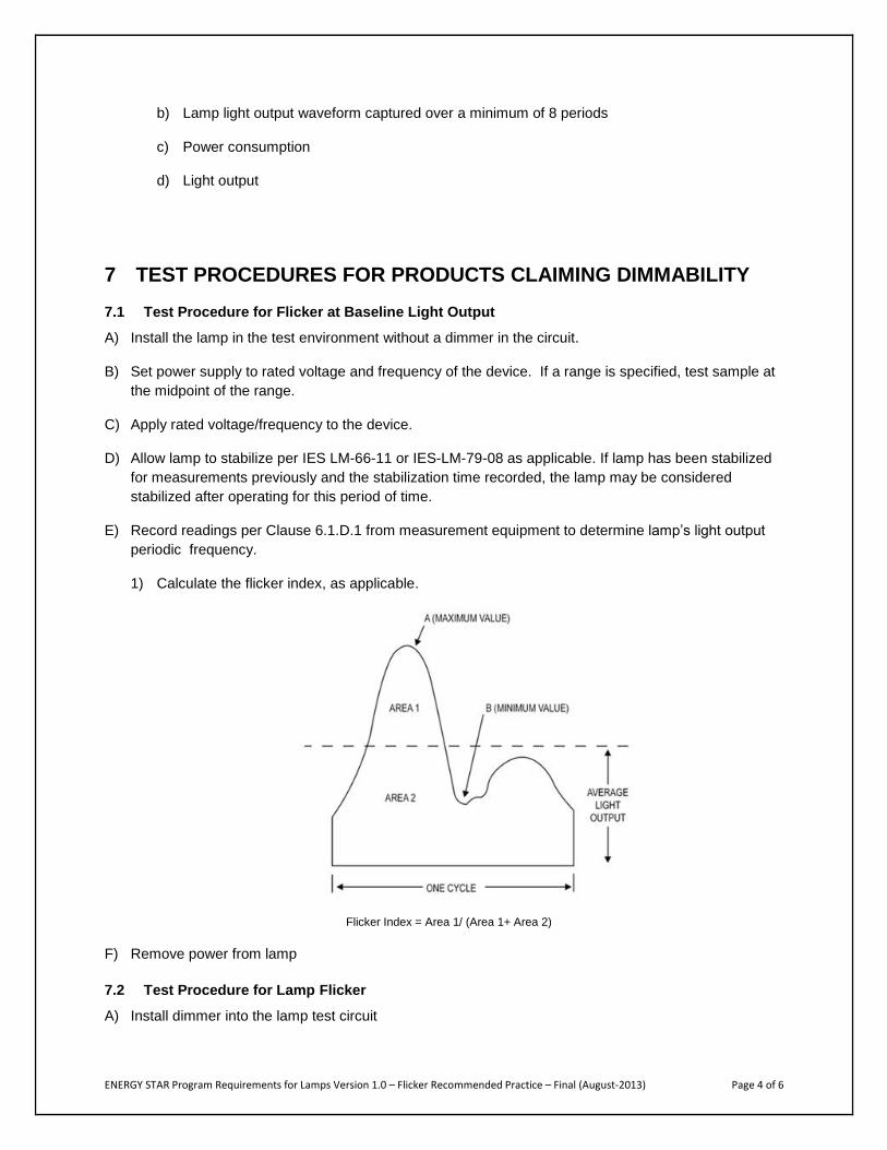
1) Calculate the flicker index, as applicable.
Flicker Index = Area 1/ (Area 1+ Area 2)
F) Remove power from lamp
7.2 Test Procedure for Lamp Flicker
A) Install dimmer into the lamp test circuit

ENERGY STAR Program Requirements for Lamps Version 1.0 – Flicker Recommended Practice – Final (August-2013) Page 5 of 6
B) Apply rated voltage/frequency to the dimmer or control device.
C) Adjust dimmer to the maximum control position.
D) Allow lamp to stabilize and verify by taking light output measurements every minute until consecutive
measurements are no more than 0.5% apart, utilizing previously recorded lamp stabilization time or
verify by mathematical means that the lamp is stabilized.
E) Record light output, electrical parameters, and waveform readings per Clause 6.1.D.1 from
measurement equipment and record percent flicker and calculate the flicker index. The flicker index
is the flicker at the MaxLO.
F) Adjust dimmer so that the light output is the lower of:
1) 20% of the MaxLO ± 5%.
2) The minimum dimming level claimed as percentage of the MaxLO ± 5%.
G) Allow lamp to stabilize and verify by taking light output measurements every minute, until consecutive
measurements are no more than 0.5% apart, utilizing previously recorded lamp stabilization time or
verify by mathematical means that the lamp is stabilized.
H) Verify that the lamp light output is still within the range in F)
1) If not, repeat step F) and G)
2) If light output is within range, record light output, electrical parameters, and waveform readings
per Clause 6.1.D.1 from measurement equipment to determine percent flicker and flicker index.
The flicker index is the flicker at the MinLO.
I) Repeat steps 7.2.A-H for each dimmer to be tested. A test setup that includes a device that allows hot
switching between dimmers may be utilized to bypass stabilization time.
J) Repeat steps 7.2.A-H for each dimmer to be tested with 4 lamps on the dimmer circuit, taking
measurements from one lamp.
8 TEST REPORT Light Source Flicker report data shall include the following test information and be submitted on the
ENERGY STAR Dimming Data Sheet:
A) Manufacturer’s name and product identification
B) Name and location of testing facility
C) Test date
D) Lamp base orientation
E) Test voltage (V)

ENERGY STAR Program Requirements for Lamps Version 1.0 – Flicker Recommended Practice – Final (August-2013) Page 6 of 6
F) Test frequency (Hz)
G) Fundamental frequency, percent flicker and flicker index at BLO
H) Electrical measurements, light output reading, flicker index and percent flicker at MaxLO for 1 and 4
lamp configurations for each dimmer tested
I) Electrical measurements, light output reading, flicker index and percent flicker at MinLO for 1 and 4
lamp configurations for each dimmer tested
J) Stabilization time and stabilization method used
K) Digitized photometric waveform data and an image of the relative photometric amplitude waveform
with a period ≥ 100ms

ENERGY STAR Program Requirements for Lamps Version 1.0 – Noise Recommended Practice - Final (August-2013) Page 1 of 5
ENERGY STAR® Program Requirements
Product Specification for Lamps Version 1.0:
Noise
Recommended Practice
August-2013
1. OVERVIEW This document provides the recommended practice for evaluating audible noise produced by a lamp.
2. APPLICABILITY The following guidelines shall be used to determine the applicability of each section of this document:
The lamp noise test method applies to all compact fluorescent lamps (CFLs) and solid state
lighting (SSL) lamps covered in the scope of the lamps specification that are marketed as
dimmable.
3. DEFINITIONS Unless otherwise specified, all terms used in this document are consistent with the definitions in the
ENERGY STAR Eligibility Criteria for Lamps.
Baseline Light Output: The baseline light output (BLO) refers to the stabilized light output of the unit
under test (UUT) is operating without a dimmer in the circuit.
Maximum Control Position: The setting on the dimmer or control device intended to achieve the
maximum light output during operation.
Maximum Light Output: The maximum light output (MaxLO) refers to the light output of the lamp when
operating with a dimmer in the circuit at the Maximum Control Position.
Minimum Dimming Level Claimed: The minimum light output level of a lamp when operated with a
dimmer in the circuit, as declared by the lamp manufacturer. Typically expressed as a percentage.
Minimum Light Output: The minimum light output (MinLO) refers to the minimum light output when the
lamp is operating with a dimmer in the circuit.
Peak Noise: The highest time-averaged sound value recorded at a measurement point during stable
operation of the UUT.
Unit Under Test: The unit under test (UUT) refers the the specific lamp sample being tested.

ENERGY STAR Program Requirements for Lamps Version1.0 – Noise Recommended Practice – Final (August-2013) Page 2 of 5
4. METHODS OF MEASUREMENT AND REFERENCE DOCUMENTS
5.1 IES Test Methods and Reference Documents
A) IES LM-66-11: 2011. IES Approved Method for Electrical and Photometric Measurements of Single-
Ended Compact Fluorescent Lamps, Illuminating Engineering Society, New York.
B) IES LM-79-08: 2008. IES Approved Method for Electrical and Photometric Measurements of Solid-
State Lighting Products, Illuminating Engineering Society, New York.
C) IES LM-54-12: 2012. IES Guide to Lamp Seasoning, Illuminating Engineering Society, New York.
D) ISO 7574-4 B.2.1: 1985. Statistical methods for determining and verifying stated noise emission
values of machinery and equipment, International Organization for Standardization, Geneva,
Swizerland.
E) ASA S12.55-2006/ISO3745:2003: 2006. Acoustical Society of America, New York.
5. RECOMMENDED PRACTICE TEST SETUP
5.2 General
A) Test Setup and Instrumentation: The test can be performed using a single microphone and rotating
the product, or by using multiple microphones.
1) Equipment required for measurement is as follows:
a) Regulated AC or DC power supply (as applicable to the lamp or transformer).
b) Multichannel oscilloscope with data storage capability or similar equipment for comparing
output readings from a photodetector.
c) Appropriate attenuator probe(s), if applicable.
d) Photodetector capable of measuring relative light output.
e) Noise level measurement equipment.
f) Microphone(s).
g) Isolated sound chamber (e.g. anechoic chamber).
B) Lamp Seasoning and Preburning: Prior to the first readings, compact fluorescent lamps (CFLs) shall
be seasoned for 100 hours in accordance with IES LM-54-12. CFLs shall be preburned in accordance
with IES LM-66-11. LED lamps shall not be seasoned.
C) Input Power for Measurements: The power requirements shall be per IES LM-66-11 or LM-79-08 as
applicable. Note: When selecting a power supply for use with integrated lamps, it is necessary to
apply an appropriate power factor when specifying the Volt-Amp rating of the power supply.
D) Ambient Temperature: Lamp testing shall take place in an ambient temperature of 25°C ± 5°C. Drafts
shall be minimized.
E) Power Meter: Power meters shall be capable of measuring to the appropriate requirements of IES
LM-66-11 or IES LM-79-08 as applicable.

ENERGY STAR Program Requirements for Lamps Version1.0 – Noise Recommended Practice – Final (August-2013) Page 3 of 5
F) Environmental Conditions: The test environment shall be clean and free from large amounts of dust
and moisture.
G) Sample Selection: Samples shall be representative of the manufacturer’s typical product. The
samples shall be clean and thoroughly inspected before testing. Any flaws or inconsistencies in the
lamp samples shall be noted. The sample(s) used for noise testing shall be the same sample(s) used
for the ENERGY STAR Flicker testing, if applicable, and can be the same sample(s) used for other
testing.
6 TEST CONDUCT
6.1 Guidance for Noise Test Procedure
A) Photometric Measurements:
1) For absolute measurements, refer to IES LM-66-11 or IES-LM-79-08 as applicable with the
exception of the guidance for lamp stabilization.
2) The photodetector used for photometric measurements shall be a silicon detector corrected to
closely fit the Commission Internationale de l’Eclairage (CIE) spectral luminous efficiency curve
(V ).
a) Ensure that the measurement equipment receives the appropriate voltage range from the
photodetector, using an amplifier if necessary.
B) Measurement Equipment:
1) The sound chamber shall provide an environment suitable for the sound testing of lamps.
External sources of noise shall be minimized.
2) The sound measurement equipment shall be capable of measuring A-weighted decibels.
3) The microphone(s) shall be placed at a distance of one (1) meter or less from the lamp to be
measured.
a) If multiple microphones are used, 6 microphones shall be placed about the lamp spaced 90°
apart and aimed at the lamp.
b) If a single microphone is used, the microphone shall be aimed at the lamp and the lamp
holding device shall be capable of moving and holding the lamp so that six measurements
about the lamp can be made 90° apart.
4) The sound level of the lamp shall be calculated from the measurement taken, with the baseline
level corrected for and in accordance with ISO 7574-4:1985, B.2.1. All other aspects of the
measurements to be taken in accordance with ANSI standard S12.55-2006/ISO3745:2003
(calibration, etc.).
C) Lamp Transfer for CFLs:
1) Care shall be exercised to maintain lamp orientation and avoid shaking or bumping the lamp
during the transfer from seasoning area.
D) Low Voltage Lamps
1) Lamps designed for operation on low voltage transformers shall be operated on a compatible
transformer specified or supplied by the lamp manufacturer.

ENERGY STAR Program Requirements for Lamps Version1.0 – Noise Recommended Practice – Final (August-2013) Page 4 of 5
2) Electrical measurements shall include characteristics of the lamp.
E) Measurements:
1) The following data shall be collected at each measurement point:
a) Light output.
b) Peak Noise Reading.
c) Microphone Position at which the Peak Noise Reading occurs (e.g. 0 degrees / opposite lamp
base).
7 TEST PROCEDURE FOR PRODUCTS CLAIMING DIMMABILITY
7.1 General Test Procedures for Noise at Baseline output
A) Install the lamp in the test environment without a dimmer in the circuit.
B) Set power supply to rated voltage and frequency of the device. If a range is specified, test sample at
the midpoint of the range.
C) Record noise readings from measurement equipment to determine sound level in dBA. This is the
control noise level.
D) Apply rated voltage/frequency to the device.
E) Allow lamp to stabilize per IES LM-66-11 or IES-LM-79-08 as applicable. If lamp has been stabilized
for measurements previously and the stabilization time recorded, the lamp may be considered
stabilized after operating for this period of time.
F) Record noise readings per Clause 6.1.E.1 from measurement equipment about the lamp to determine
the peak sound level in dBA. This is the noise at the Baseline Light Output (BLO).
1) If using a single microphone, note the position with the highest sound level (if applicable).
G) Remove power from lamp.
7.2 General Test Procedures for Noise on a Dimmer
A) Install dimmer into the lamp test circuit.
1) The dimmer shall be located outside of the sound chamber.
B) Apply rated voltage/frequency to the dimmer or control device.
C) Adjust dimmer to the maximum control position.
D) Allow lamp to stabilize and verify by taking light output measurements every minute until consecutive
measurements are no more than 0.5% apart, utilizing previously recorded lamp stabilization time or
verify by mathematical means that the lamp is stabilized.
E) Record noise readings per Clause 6.1.E.1 from measurement equipment about the lamp to determine
the peak sound level in dBA. This is the noise at the MaxLO.
F) Adjust dimmer so that the light output is the lower of:

ENERGY STAR Program Requirements for Lamps Version1.0 – Noise Recommended Practice – Final (August-2013) Page 5 of 5
1) 20% of the MaxLO ± 5%.
2) The minimum dimming level claimed as a percentage of the MaxLO ± 5%.
G) Allow lamp to stabilize and verify by taking light output measurements every minute until consecutive
measurements are no more than 0.5% apart, utilizing previously recorded lamp stabilization time or
verify by mathematical means that the lamp is stabilized.
H) Verify that the lamp light output is still within the range in F).
1) If not, repeat step A) and G).
2) If light output is within range, record noise readings per Clause 6.1.E.1 from measurement
equipment about the lamp to determine the peak sound level in dBA. This is the noise at MinLO.
I) Repeat steps 7.2A-H for each dimmer to be tested. A test setup that includes a device that allows hot
switching between dimmers may be utilized to bypass stabilization time.
J) Repeat steps 7.2A-H for each dimmer to be tested with 4 lamps on the dimmer circuit, taking
measurements from a single lamp.
8 TEST REPORT Lamp Noise on a Dimmer report data shall include the following test information and be submitted on the
ENERGY STAR Dimming Data Sheet:
A) Manufacturer’s name and product identification.
B) Name and location of testing facility.
C) Test date.
D) Lamp base orientation.
E) Test voltage (V).
F) Test frequency (Hz).
G) Stabilization time and method used.
H) Noise at BLO.
I) Distance between the microphone and the UUT.
J) Noise and light output reading at MaxLO for 1 and 4 lamp configurations for each dimmer tested.
K) Noise and light output reading at MinLO for 1 and 4 lamp configurations for each dimmer tested.