Managing and automating the accounts payable process to realize savings, compliance and growth

Energy savings by process integration
Francois Marechal Industrial Energy Systems LaboratoryMechanical Engineering Department
Ecole Polytechnique Fédérale de Lausanne
Monday 22 February 2010
fran
cois
.mar
echa
l@ep
fl.c
h ©La
bora
tory
for
Indu
stri
al E
nerg
y Sy
stem
s -
LEN
I ISE
-STI
-EPF
L –
Mar
sh 2
006
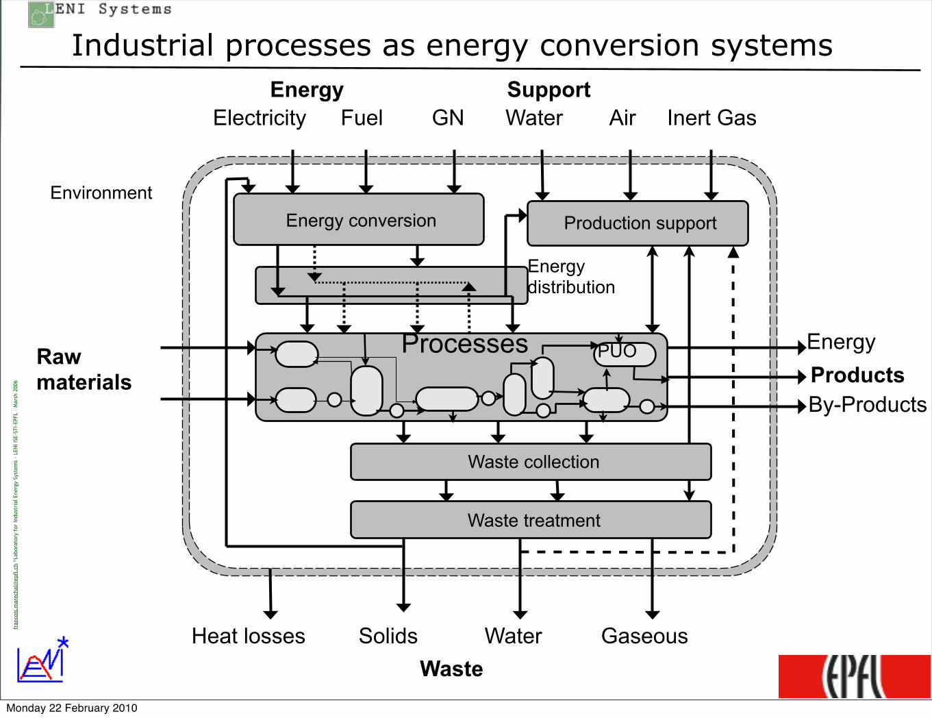
Energy conversion Production support
Waste treatment
Environment
EnergyWater
Rawmaterials Products
By-Products
Heat losses WaterSolids
Energy
Air
Waste collection
Gaseous
Inert GasFuelElectricity GN
Energydistribution
Waste
Processes PUO
Support
Industrial processes as energy conversion systems
Monday 22 February 2010

fran
cois
.mar
echa
l@ep
fl.c
h ©La
bora
tory
for
Indu
stri
al E
nerg
y Sy
stem
s -
LEN
I ISE
-STI
-EPF
L –
Mar
sh 2
006
3
The Energy Efficiency Goal
Maximise horizontal flows
Minimise vertical flows
Energy Conversion
Productionsupport
Waste treatment
Processes
Losses Waste
Emissions
RawMaterials
Energy - WaterSolvent
ProductsServices
Monday 22 February 2010
fran
cois
.mar
echa
l@ep
fl.c
h ©La
bora
tory
for
Indu
stri
al E
nerg
y Sy
stem
s -
LEN
I ISE
-STI
-EPF
L –
Mar
sh 2
006
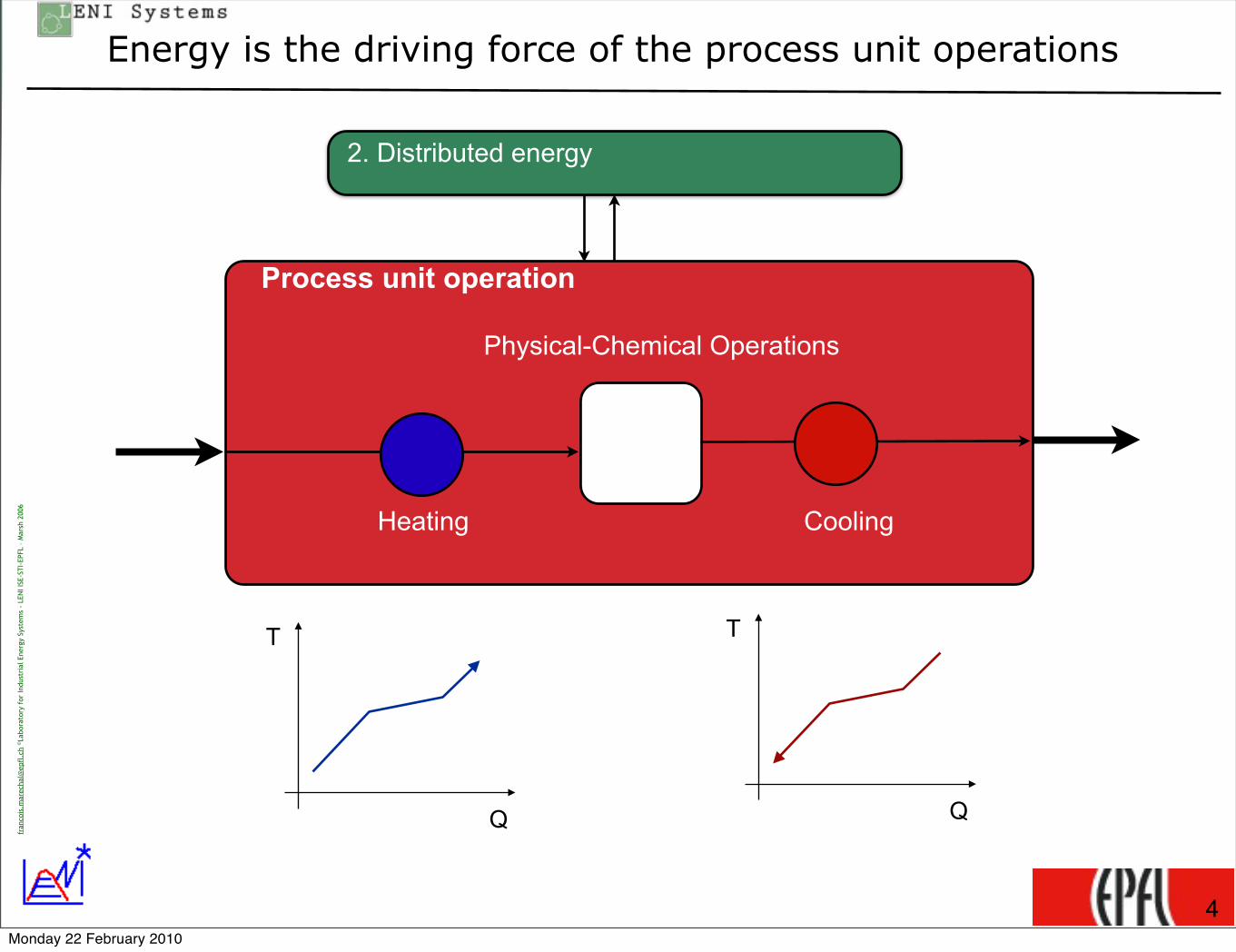
Energy is the driving force of the process unit operations
Process unit operation
2. Distributed energy
Heating
Physical-Chemical Operations
Cooling
4
T
Q
T
Q
Monday 22 February 2010
fran
cois
.mar
echa
l@ep
fl.c
h ©La
bora
tory
for
Indu
stri
al E
nerg
y Sy
stem
s -
LEN
I ISE
-STI
-EPF
L –
Mar
sh 2
006
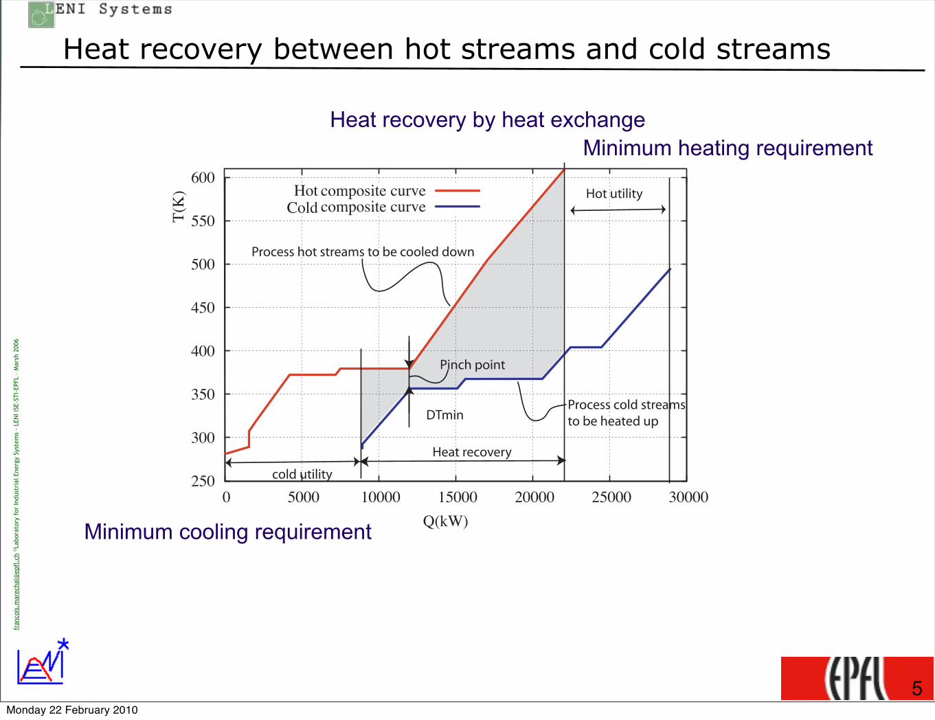
Heat recovery between hot streams and cold streams
Heat recovery
Hot utility
cold utility 2 5 0
3 0 0
3 5 0
4 0 0
4 5 0
5 0 0
5 5 0
6 0 0
0 5 0 0 0 1 0 0 0 0 1 5 0 0 0 2 0 0 0 0 2 5 0 0 0 3 0 0 0 0
T ( K
)
Q ( k W )
Cold c o m p o s i t e c u r v e Hot c o m p o s i t e c u r v e
Process hot streams to be cooled down
Process cold streamsto be heated up
Pinch point
DTmin
Heat recovery by heat exchangeMinimum heating requirement
Minimum cooling requirement
5Monday 22 February 2010

More -in / More-out
Heat recovery
Hot utility
cold utility 2 5 0
3 0 0
3 5 0
4 0 0
4 5 0
5 0 0
5 5 0
6 0 0
0 5 0 0 0 1 0 0 0 0 1 5 0 0 0 2 0 0 0 0 2 5 0 0 0 3 0 0 0 0
T ( K
)
Q ( k W )
Cold c o m p o s i t e c u r v e Hot c o m p o s i t e c u r v e
Process hot streams to be cooled down
Process cold streamsto be heated up
Pinch point
DTmin
Energy saving
potential
Present heat requirement
Waste heat =
inefficiencyThe inefficiency is heating the environmentusing the fuel that you buy ....
Monday 22 February 2010

Laboratory for Industrial Energy SystemsLENI -ISE-STI-EPFL
©F.
Mar
echa
l LEN
I-IS
E-ST
I-EP
FL 2
004
Grand composite curves
7
Enthalpy-Temperature profile of the heating requirement
Enthalpy-Temperature profile of the cooling requirement
Monday 22 February 2010

fran
cois
.mar
echa
l@ep
fl.c
h ©La
bora
tory
for
Indu
stri
al E
nerg
y Sy
stem
s -
LEN
I ISE
-STI
-EPF
L –
Mar
sh 2
006
STI ISE LENI
Reducing process heat requirement
‣Plus-Minus principle
8
250
300
350
400
450
500
550
600
0 5000 10000 15000 20000 25000 30000
T(K
)
Q(kW)
Cold composite curveHot composite curve
Figure 3: The composite curves for identifying key streams and process unit operations
of a stream. It can be the inlet of a stream or of the segments created if a fluid phase changeoccurs.
Referring to the onion diagram, changing the temperature level of a requirement is typicallyobtained by changing the operating conditions of the process unit operations while keeping as ageneral goal the e!ciency of the conversion of raw materials to products and as constraints thefinal products to be delivered by the process. Among the important streams to be considered,the heat of reactions typically introduce near vertical lines in the composite curves, when anexothermic reaction occurs below the pinch temperature or an endothermic reaction occurs abovethe pinch temperature, one could imagine to modify the operating pressure or temperature oreven change the reactor type, i.e. change from an adiabatic reactor to a heat transfer typereactor. Another option would be to realise the reaction in several steps in order to maintainthe temperature as low as possible (if possible below the pinch point) for endothermic reactionsand as high as possible (if possible above the pinch point) for exothermic reactions. This is forexample what is realised when adding a pre-reformer in a steam methane reforming process forhydrogen production. In such process, the pinch temperature is the high temperature of thereforming reaction. By realising the reformation in two steps, the heat of reaction of the pre-reformer becomes a cold stream below the pinch temperature while reducing in the same timethe heat requirement of the remaining reforming reaction above the pinch temperature. Thiscan be understood as a chemical heat pump that uses heat from the heat source to reduce therequirement in the heat sink above the pinch point temperature.
When fluid phase change occurs near the pinch point, changing the pressure of the phase
7
Monday 22 February 2010

fran
cois
.mar
echa
l@ep
fl.c
h ©La
bora
tory
for
Indu
stri
al E
nerg
y Sy
stem
s -
LEN
I ISE
-STI
-EPF
L –
Mar
sh 2
006
STI ISE LENI
Heat pump integration from below to above
9
hot stream at a lower temperature. Changing the operating pressure of one distillation columnwill allow one to change the temperature of the requirement around the pinch point. Decreasingthe column pressure will allow one to shift the reboiler from above to below the pinch point,while increasing the pressure will transfer the condenser from below to above the pinch point.This would be easy to do when the column is fed with a liquid. Considering that most of theseparation systems proceed with more than one column, changing the pressure of one columnwith respect to the other will allow to save energy by heat integration. An example of such amodification is given in Figure 5 where the pressure of the first column is increased to relocate itscondenser above the pinch point. This modification assumes that the hydrodynamics of column1 has been verified with the new conditions. The modification leads as well to a modification ofthe pinch point location.
3 Integration of heat pumps
3.1 Mechanical compression cycle heat pumps
The most common heat pump is the mechanical compression cycle illustrated in Figure 6. A fluid(typically a refrigerant) is evaporated by cooling a process stream (Q(!)), using the mechanicalpower (W+), the pressure is changed and the heat is send back by condensing the evaporatedfluid at a higher pressure and temperature. Considering the temperature of evaporation (T (!))and of condensation (T (+)), the mechanical power may be approximated by applying an e!ciency(!Carnot) to the reversible work of heat pumping (2).
W+ = Q(!) (T (+) ! T (!))T (!)!Carnot
(2)
The heat load of the condensation (Q(+)) is equal to W+ + Q(!). The advantage of a heatpump is the fact that is modifies the temperature level of a heat source to make it available at ahigher more useful temperature. A heat pump will therefore be attractive when the heat sourceis a free source (e.g. the environment or waste heat) and when the heat can be delivered tosatisfy an energy requirement of the process.
Pinch analysis identifies the possible heat recovery between the hot and the cold streams.It also defines the enthalpy-temperature profile of the process heat source and the process heatsink. The heat source will become the cold source of the heat pump (i.e. the hot stream of theevaporation) and the heat sink profile defines the energy requirements of the process that definesthe hot source (cold stream of the condenser). From the definition of the ”plus-minus” principle,it can be seen that the only feasible possibility for appropriately integrating a heat pump inthe system with a heat exchanger network is to introduce a new cold stream below the pinchtemperature. This stream will receive heat from a hot stream of the heat source sub-system andsend the heat back after compression in the heat sink sub-system by introducing a new hot streamabove the pinch point. The optimal integration of the heat pump system will try to maximisethe heat load (Q(!)), while minimising the mechanical power (W+). The temperature lift hastherefore to be minimised. The mechanical power of the heat pump can be estimated usingthe Carnot factor computed from the temperatures of Q(!) and Q(+), therefore the integrationof the heat pump may be calculated by Eq. 3. When pumping heat from below to above thepinch point the energy saving is equal to Q(+) at the expense of W+ of mechanical power. Theintegration of the heat pump if explained on figure 7. It has to be noted that when the heatpump is not located to pump heat from below to above the pinch point, the benefit of the heatpump (that may be apparently profitable at its location) is cancelled by the heat integration of
9
005522
005544
000055
005555
000066
0000002211 0000000011 00000066 00000044 00000022 00
T(K
)T
(K)
))WWkk((QQ
00000088
Figure 7: Representation of a heat pump
Absorption heat pumps and heat transformers proceed with three streams. Absorptionheat pumps (Figure 8) have two cold streams and one hot stream. The cold streams at lowtemperature will take heat in the exothermic sub-system below the pinch temperature. The heatpumped will be recovered above the pinch point in the condenser and the absorber while a coldstream corresponding to the boiler at high temperature will drive the heat pumping e!ect. Thebenefit of the absorption heat pump is therefore the heat load pumped below the pinch. Whenoptimising the flowrate of the absorption heat pump, there will be 3 potential pinch points, eachone associated to the evaporation and the condensation levels of the heat pump. It should benoted that absorption heat pumps may profit from self-su"cient zones above the pinch pointto maximise their flowrate and therefore the amount of heat pumped in the system. In heattransformers (Figure 9), the cold streams are at the medium temperature while one hot streamwill be at low temperature and one at high temperature. Therefore the optimal integration of theheat transformer will be obtained by driving the heat below the pinch temperature to relocatepart of the heat in the high temperature hot stream above the pinch point. The heat transformerwill maximise its flowrate by using the energy of self-su"cient zones below the pinch point.
12
Cost saving = Q(1! !b
COP
cel
cfuel)
Energy saving = Q(1! !b
COP
1!grid
)
COP =Q!
W+
Monday 22 February 2010

FM_07/ 2000
Cogeneration
Hot Utility : 6854 kWSelf sufficient "Pocket"
Ambient temperatureCold utility : 6948 kW
Refrigeration : 1709 kW 250
300
350
400
450
500
550
600
0 2000 4000 6000 8000 10000 12000
T(K
)
Q(kW)
Cogeneration : above or below the pinch point
LossesHeatElectricity
Heat to envElec
cfuel
!th! !ece
!thSpecific cost of heat
E =Q!e
!thmfuelLHVfuel =
Q
!th
=> never supply the inefficiency
Monday 22 February 2010

fran
cois
.mar
echa
l@ep
fl.c
h ©La
bora
tory
for
Indu
stri
al E
nerg
y Sy
stem
s -
LEN
I ISE
-STI
-EPF
L –
Mar
sh 2
006
Energy savings by cogeneration
‣Energy savings from energy conversion
11Monday 22 February 2010

Laboratory for Industrial Energy SystemsLENI -ISE-STI-EPFL
©F.
Mar
echa
l LEN
I-IS
E-ST
I-EP
FL 2
004
Steam network integration
12fl
ue g
ases
Process 1 Process 2
HRB
C
Cooling system
Figure 17: Steam distribution network as a way of realising process streams heat exchange andconverting available exergy from a process
24
Monday 22 February 2010
fran
cois
.mar
echa
l@ep
fl.c
h ©La
bora
tory
for
Indu
stri
al E
nerg
y Sy
stem
s -
LEN
I ISE
-STI
-EPF
L –
Mar
sh 2
006
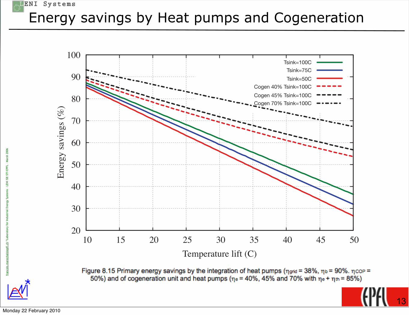
Energy savings by Heat pumps and Cogeneration
20
30
40
50
60
70
80
90
100
10 15 20 25 30 35 40 45 50
Ener
gy s
avin
gs
(%)
Temperature lift (C)
Tsink=100C
Tsink=75C
Tsink=50C
Cogen 40% Tsink=100C
Cogen 45% Tsink=100C
Cogen 70% Tsink=100C
13Monday 22 February 2010

fran
cois
.mar
echa
l@ep
fl.c
h ©La
bora
tory
for
Indu
stri
al E
nerg
y Sy
stem
s -
LEN
I ISE
-STI
-EPF
L –
Mar
sh 2
006
Conclusions
‣1) System boundaries‣Consider the whole system
‣Consider energy conversion, production support and waste management
‣Waste streams to environment
‣ Increase the perimeter (e.g. industrial clusters)
‣2)Pinch Analysis‣Heat recovery
‣Process modifications
‣3) Energy conversion‣heat pumping (from below to above)
‣ cogeneration (above or below)
‣Do not supply efficiently your inefficiency
14Monday 22 February 2010

fran
cois
.mar
echa
l@ep
fl.c
h ©La
bora
tory
for
Indu
stri
al E
nerg
y Sy
stem
s -
LEN
I ISE
-STI
-EPF
L –
Mar
sh 2
006
‣Examples of applications
15Monday 22 February 2010

fran
cois
.mar
echa
l@ep
fl.c
h ©La
bora
tory
for
Indu
stri
al E
nerg
y Sy
stem
s -
LEN
I ISE
-STI
-EPF
L –
Mar
sh 2
006
Examples in the chemical industry
16
‣Ammonia process‣Redesign of the ammonia synthesis reactor
‣maximise CHP by steam network integration
‣High temperature integration (preheating + pre-reformer)
‣High temperature cogeneration
Table 4: Examples of energy savings in chemical processes (the reference is the fossil fuel con-sumption in the process, numbers is brackets represents the energy saving percentage)
Ethylen Present situation Process integrationFossil Fuel 100 55 (45% )Electricity 18 7 (59%)Primary energy 147 74 (49%)
Ammonia Present situation Process integration High temp. cogen.Fossil Fuel 100 38 (62%) 77 (33%)Electricity 0 13 -3Primary energy (!grid =38%) 100 71 (29%) 70 (30%)Primary energy (!grid =58%) 100 60 (40%) 73 (27%)
the integration was the mass integration between products and by products. The energy savingscomes from the site wide integration that reduces the energy requirement by 56% in comparisonwith a not integrated site (obviously, in the present situation a certain level of integration isalready reached). The site pinch point was used to identify some process modifications thatallow heat recovery between production units in the chemical site. The heat recovery is realisedusing the steam network as a heat transfer media and reduces the site energy requirement by30 %. The process modifications are only valid for the site integration and have no interest if itconcerns the same process but not integrated.
Table 5: Industrial site integration results, the reference is the fossil fuel used in the site, reportedelectricity concerns only cogenerated electricity
Vinyl Chloride Site Present situation Site integration Gas turbineFossil Fuel 100 57 (43%) 88 (12%)Electricity -4 -13 (x2.5) -38 (x9)Primary energy 91 24.2 (74%) -12 (113 %)
7 ConclusionsProcess integration techniques are used in order to reduce the energy consumption in a givenprocess. When waste heat is available from a process, the heat can be used for other purposes likeheating. Extending the system boundaries from the process system to its neighbor process or builtarea will allow to recover the waste energy but also change the pinch point location and thereforethe decisions for energy e!ciency improvement. The process integration perspective allows fora systematic analysis of the synergies in a system and therefore to target the energy e!ciencyimprovement with a holistic and systemic perspective. The reported energy savings of more than30 % show that considerable amount of energy can be saved by the proper integration of processheat sources and sinks with the appropriate integration of heat pumping and polygeneration
11
technologies. Process integration also shows the importance of extending as much as possiblethe system boundaries which in turns requires new contracting mechanism (like energy servicesor waste management) to realise a large scale process integration.
References[1] Helen Becker. Intégration eau-énergie dans une laiterie. Master’s thesis, Ecole Polytechnique
Federale de Lausanne, 2007.
[2] D. Brown, F. Marechal, and J. Paris. A dual representation for targeting process retrofit,application to a pulp and paper process. Applied Thermal Engineering, Applied Thermalengineering(25):1067–1082, 2005.
[3] Boris Kalitventze!, Francois Marechal, and Herve Closon. Better solutions for process sus-tainability through better insight in process energy integration. Applied Thermal Engineering,21(13-14):1349–1368, 2001.
[4] F. Marechal, H. Closon, B. Kalitventze!, and S. Pierucci. A tool for optimal synthesis ofindustrial refrigeration systems : application to an olefins plants. AIChE annual meeting,New-Orleans, March 2002, (Paper 89g), March 2002.
[5] F. Marechal and B. Kalitventze!. Energy integration of industrial sites: tools, methodologyand application. Applied Thermal Engineering, 18(11):921–933, 1998.
[6] Damien Muller. Web-Based Tools for Energy Management in Large Companies Applied toFood Industry. PhD thesis, ECOLE POLYTECHNIQUE FEDERALE DE LAUSANNE,THESE NË"3785 (2007), 2007.
[7] Zoe Perin-Levasseur and Francois Marechal. Annual report 2007, e#cient energy conversionin the pulp and paper industry. Annual report, Ecole Polytechnique Fédérale de Lausanne,2007.
[8] D. Tsahalis and et al. An expert system of energy savings technologies for the process industry.Technical report, EU Project no JOE3950020, program NNE-JOULE C final report, 1998.
12
Monday 22 February 2010

fran
cois
.mar
echa
l@ep
fl.c
h ©La
bora
tory
for
Indu
stri
al E
nerg
y Sy
stem
s -
LEN
I ISE
-STI
-EPF
L –
Mar
sh 2
006
Energy conversion system
17
!"#$ %& '(# )*#++,*# -#"#-+ )*.).+#/ 01 '(# 2.3).+%'# 2,*"# 4$4-1+%+ 5#*# /%6#*#$' &*.3 '(# .$#.& '(# #7%+'%$8 +1+'#39 %' (4+ 0##$ /#2%/#/ $.' '. 2(4$8# '(# )*#++,*# -#"#-+ %$ .*/#* '. -#4"# '(#+#)4*43#'#*+ .& '(# #7%+'%$8 +'#43 $#'5.*: ,$2(4$8#/;
<(# ,+# .& '(# +'#43 $#'5.*: %$'#8*4'%.$ 3./#- /#+2*%0#/ %$ =#&; >?@A 4--.5+ '. 2.3),'# '(#.)'%34- 2.30%$#/ (#4' 4$/ ).5#* )*./,2'%.$ 04+#/ .$ '(# (#4' #72#++ .& '(# )*.2#++ %'+#-&B#72-,/%$8 '(# &,3#+ .& '(# (.' (#4' ,'%-%'1C; D$ #E2%#$21 .& FG;HI BJ%8; FC %+ .0'4%$#/ 3#4$%$8'(4' FG;HI .& '(# (%8( '#3)#*4',*# (#4' #72#++ %+ '*4$+&.*3#/ %$'. 3#2(4$%24- ).5#*9 '(# *#+'BKL;MIC 0#%$8 #"42,4'#/ 4' -.5 '#3)#*4',*# 01 '(# 2..-%$8 +1+'#3; N$ '(%+ +.-,'%.$9 5# (4"# '.3#$'%.$ '(4' .$-1 @LI .& '(# 3#2(4$%24- ).5#* %+ )*./,2#/ 01 '(# #7)4$+%.$ &*.3 '(# (%8()*#++,*# -#"#- '. '(# 2.$/#$+4'%.$ +1+'#39 5(%-# O?I *#+,-' &*.3 '(# #7)4$+%.$ 0#'5##$ -#"#-+ %$'(# +#-&P+,E2%#$' Q.$# B*#4- 2.30%$#/ (#4' 4$/ ).5#* )*./,2'%.$C; <(%+ %+ 4$ %3).*'4$' *#+,-'R 5#24$$.' %8$.*# '(# ).'#$'%4- .& SS+#-&P+,E2%#$' Q.$#+TT B).2:#'+C 5(#$ 2.30%$#/ (#4' 4$/ ).5#* %+2.$+%/#*#/;
J%8; H; U2(#34'%2 *#)*#+#$'4'%.$ .& '(# #7%+'%$8 +'#43 $#'5.*:;
J%8; F; U'#43 $#'5.*: %$'#8*4'%.$ &.* (#4' #72#++ "4-.*%+4'%.$;
?KHM !" #$%&'()*'+), )' $%" - .//%&)0 12)34$% 5*6&*))3&*6 78 97::8; 8<=>?8<@A
Monday 22 February 2010
fran
cois
.mar
echa
l@ep
fl.c
h ©La
bora
tory
for
Indu
stri
al E
nerg
y Sy
stem
s -
LEN
I ISE
-STI
-EPF
L –
Mar
sh 2
006
Example chemical industry
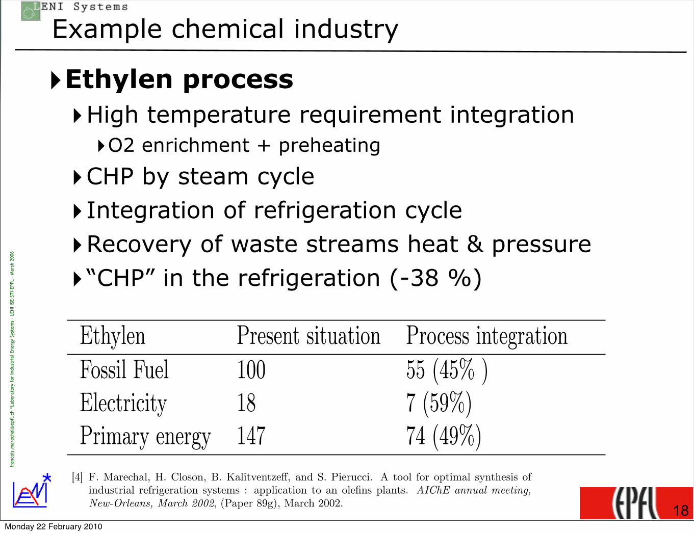
‣Ethylen process‣High temperature requirement integration‣O2 enrichment + preheating
‣CHP by steam cycle
‣Integration of refrigeration cycle
‣Recovery of waste streams heat & pressure
‣“CHP” in the refrigeration (-38 %)
18
Table 4: Examples of energy savings in chemical processes (the reference is the fossil fuel con-sumption in the process, numbers is brackets represents the energy saving percentage)
Ethylen Present situation Process integrationFossil Fuel 100 55 (45% )Electricity 18 7 (59%)Primary energy 147 74 (49%)
Ammonia Present situation Process integration High temp. cogen.Fossil Fuel 100 38 (62%) 77 (33%)Electricity 0 13 -3Primary energy (!grid =38%) 100 71 (29%) 70 (30%)Primary energy (!grid =58%) 100 60 (40%) 73 (27%)
the integration was the mass integration between products and by products. The energy savingscomes from the site wide integration that reduces the energy requirement by 56% in comparisonwith a not integrated site (obviously, in the present situation a certain level of integration isalready reached). The site pinch point was used to identify some process modifications thatallow heat recovery between production units in the chemical site. The heat recovery is realisedusing the steam network as a heat transfer media and reduces the site energy requirement by30 %. The process modifications are only valid for the site integration and have no interest if itconcerns the same process but not integrated.
Table 5: Industrial site integration results, the reference is the fossil fuel used in the site, reportedelectricity concerns only cogenerated electricity
Vinyl Chloride Site Present situation Site integration Gas turbineFossil Fuel 100 57 (43%) 88 (12%)Electricity -4 -13 (x2.5) -38 (x9)Primary energy 91 24.2 (74%) -12 (113 %)
7 ConclusionsProcess integration techniques are used in order to reduce the energy consumption in a givenprocess. When waste heat is available from a process, the heat can be used for other purposes likeheating. Extending the system boundaries from the process system to its neighbor process or builtarea will allow to recover the waste energy but also change the pinch point location and thereforethe decisions for energy e!ciency improvement. The process integration perspective allows fora systematic analysis of the synergies in a system and therefore to target the energy e!ciencyimprovement with a holistic and systemic perspective. The reported energy savings of more than30 % show that considerable amount of energy can be saved by the proper integration of processheat sources and sinks with the appropriate integration of heat pumping and polygeneration
11
technologies. Process integration also shows the importance of extending as much as possiblethe system boundaries which in turns requires new contracting mechanism (like energy servicesor waste management) to realise a large scale process integration.
References[1] Helen Becker. Intégration eau-énergie dans une laiterie. Master’s thesis, Ecole Polytechnique
Federale de Lausanne, 2007.
[2] D. Brown, F. Marechal, and J. Paris. A dual representation for targeting process retrofit,application to a pulp and paper process. Applied Thermal Engineering, Applied Thermalengineering(25):1067–1082, 2005.
[3] Boris Kalitventze!, Francois Marechal, and Herve Closon. Better solutions for process sus-tainability through better insight in process energy integration. Applied Thermal Engineering,21(13-14):1349–1368, 2001.
[4] F. Marechal, H. Closon, B. Kalitventze!, and S. Pierucci. A tool for optimal synthesis ofindustrial refrigeration systems : application to an olefins plants. AIChE annual meeting,New-Orleans, March 2002, (Paper 89g), March 2002.
[5] F. Marechal and B. Kalitventze!. Energy integration of industrial sites: tools, methodologyand application. Applied Thermal Engineering, 18(11):921–933, 1998.
[6] Damien Muller. Web-Based Tools for Energy Management in Large Companies Applied toFood Industry. PhD thesis, ECOLE POLYTECHNIQUE FEDERALE DE LAUSANNE,THESE NË"3785 (2007), 2007.
[7] Zoe Perin-Levasseur and Francois Marechal. Annual report 2007, e#cient energy conversionin the pulp and paper industry. Annual report, Ecole Polytechnique Fédérale de Lausanne,2007.
[8] D. Tsahalis and et al. An expert system of energy savings technologies for the process industry.Technical report, EU Project no JOE3950020, program NNE-JOULE C final report, 1998.
12
Monday 22 February 2010

fran
cois
.mar
echa
l@ep
fl.c
h ©La
bora
tory
for
Indu
stri
al E
nerg
y Sy
stem
s -
LEN
I ISE
-STI
-EPF
L –
Mar
sh 2
006
Some examples of application
‣Kraft Pulp and Paper process‣Lignin is a fuel & process stream
‣Barks from raw material is a resource
‣Cogen by steam integration
‣Recycling water = recycling heat
‣Heat exchanger network !
19
Kratf process Present situation Process modification Heat exchangersFossil fuel 100.0 28.5(71.47% ) 2.3 (97.74%)Biomass 269.2 269.2 269.2Electricity 353.1 289.8 (17.92%) 322.9 (8.56% )Primary energy 1029.2 791.2 (23.12%)) 851.9 (17.22%)Cogeneration 5.6 68.9 (x12.3) 35.9 (x6.4)Primary energy cogen 354.3 116.4 (67.16%) 177.1 (50.03% )
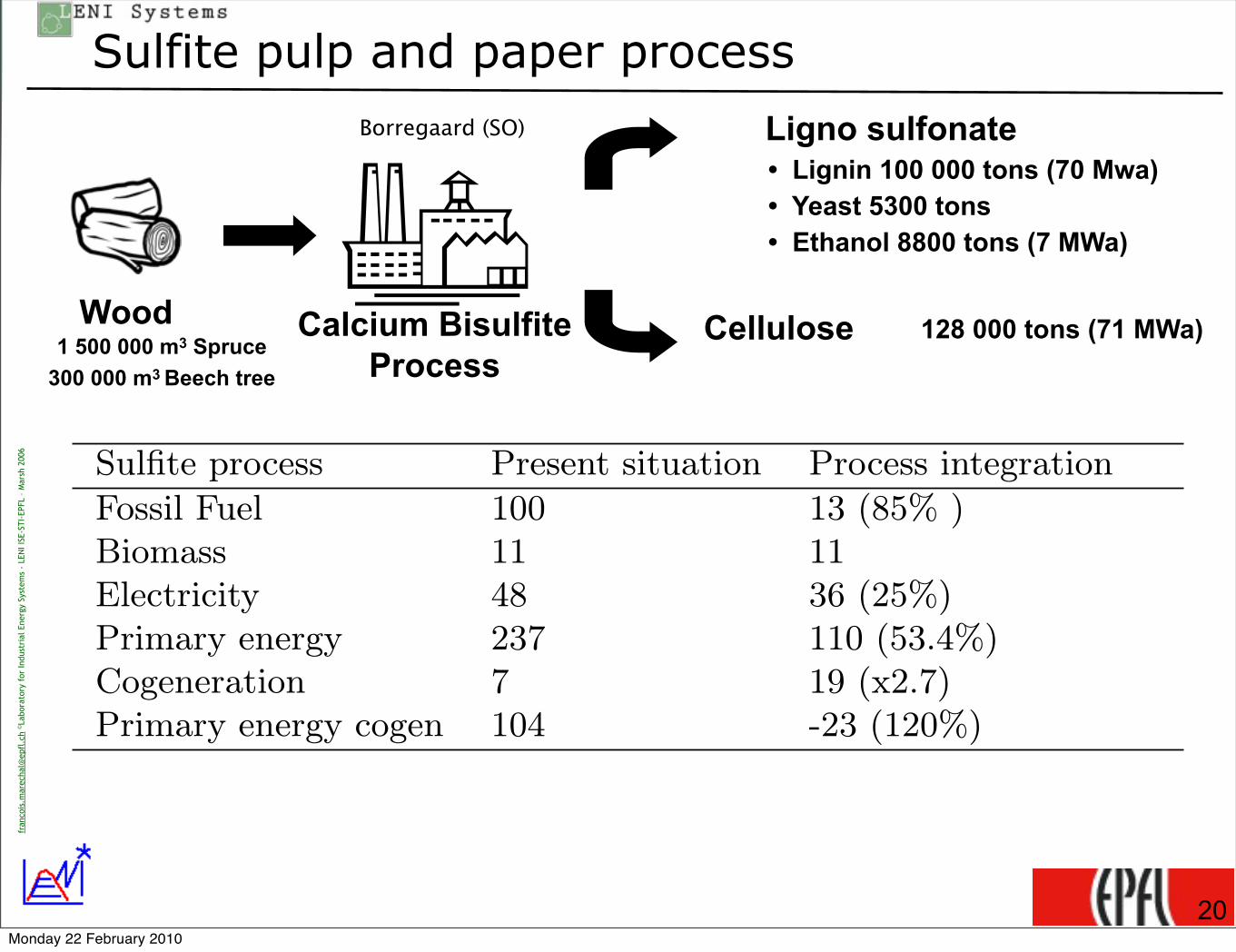
Sulfite process Present situation Process integrationFossil Fuel 100 13 (85% )Biomass 11 11Electricity 48 36 (25%)Primary energy 237 110 (53.4%)Cogeneration 7 19 (x2.7)Primary energy cogen 104 -23 (120%)
Table 2: Energy savings in the pulp and paper industry (data in [kJ/t dry pulp])
by combustion. The process under study realises mass integration by producing ethanol andlignosulfonate as by-products (biorefinery concepts). Paper is not produced in this site. Due tothe high level of cogeneration obtained when recycling the chemicals in the process, the primaryenergy consumed in the process is negative. This is explained by the electricity to primary energyconversion factor (!grid = 38%).
6.2 Food industryDue to the limited temperature level of the process unit operations, the food industry is a perfectcandidate for the integration of heat pumping and cogeneration (see table 3). Heat pumping maybe realised not only between process streams but also by using the heat of the environment. Aspecial case is the use of the refrigeration system as a heat source for the process. In thechocolate process test case ([6]), the process integration solution concerns a boiler to supplythe heat to the process and reports only the heat recovery potential, while the heat pump andcogeneration solution combines a heat pump that recovers the heat of the refrigeration systemsand a cogeneration with a gas engine.
In the dairy process ([1]), heat from the evaporation process is recovered using a mechanicalvapour recompression device. The recompressed flow is computed to reach the optimum integra-tion allowing for the best integration of a gas engine as a cogeneration unit, the heat recoveryfrom the refrigeration system and from the compressed air production. In the food processingprocesses, the heat/cold storage tanks are required to make the heat recovery possible betweendi!erent period of operation. These tanks are also used to realise the mass integration andrecycle water in the process. The reported case corresponds also to 30% water savings.
6.3 Chemical processesFor the chemical industry (table 4), 2 di!erent processes are reported, the ethylen ([8], [4]) and theammonia process ([3]). Ethylen and ammonia processes cover the whole range of temperature.A pinch point at very high temperature is observed in both processes which means that theprocess becomes a heat source at very high temperature and that actions to reduce the hightemperature heat requirement together with the optimal integration of the combined heat and
9
Monday 22 February 2010
fran
cois
.mar
echa
l@ep
fl.c
h ©La
bora
tory
for
Indu
stri
al E
nerg
y Sy
stem
s -
LEN
I ISE
-STI
-EPF
L –
Mar
sh 2
006
Sulfite pulp and paper process
20
Kratf process Present situation Process modification Heat exchangersFossil fuel 100.0 28.5(71.47% ) 2.3 (97.74%)Biomass 269.2 269.2 269.2Electricity 353.1 289.8 (17.92%) 322.9 (8.56% )Primary energy 1029.2 791.2 (23.12%)) 851.9 (17.22%)Cogeneration 5.6 68.9 (x12.3) 35.9 (x6.4)Primary energy cogen 354.3 116.4 (67.16%) 177.1 (50.03% )
Sulfite process Present situation Process integrationFossil Fuel 100 13 (85% )Biomass 11 11Electricity 48 36 (25%)Primary energy 237 110 (53.4%)Cogeneration 7 19 (x2.7)Primary energy cogen 104 -23 (120%)
Table 2: Energy savings in the pulp and paper industry (data in [kJ/t dry pulp])
Black liquor, composed of lignin and chemicals, is converted into useful heat by combustion.The process under study realises mass integration by producing ethanol and lignosulfonate asby-products (biorefinery concepts). Paper is not produced in this site. Due to the high level ofcogeneration obtained when recycling the chemicals in the process, the primary energy consumedin the process is negative. This is explained by the electricity to primary energy conversion factor(!grid = 38%).
6.2 Food industryDue to the limited temperature level of the process unit operations, the food industry is a perfectcandidate for the integration of heat pumping and cogeneration (see table 3). Heat pumping maybe realised not only between process streams but also by using the heat of the environment. Aspecial case is the use of the refrigeration system as a heat source for the process. In thechocolate process test case ([6]), the process integration solution concerns a boiler to supplythe heat to the process and reports only the heat recovery potential, while the heat pump andcogeneration solution combines a heat pump that recovers the heat of the refrigeration systemsand a cogeneration with a gas engine.
In the dairy process ([1]), heat from the evaporation process is recovered using a mechanicalvapour recompression device. The recompressed flow is computed to reach the optimum integra-tion allowing for the best integration of a gas engine as a cogeneration unit, the heat recoveryfrom the refrigeration system and from the compressed air production. In the food processingprocesses, the heat/cold storage tanks are required to make the heat recovery possible betweendi!erent period of operation. These tanks are also used to realise the mass integration andrecycle water in the process. The reported case corresponds also to 30% water savings.
6.3 Chemical processesFor the chemical industry (table 4), 2 di!erent processes are reported, the ethylen ([8], [4]) and theammonia process ([3]). Ethylen and ammonia processes cover the whole range of temperature.A pinch point at very high temperature is observed in both processes which means that theprocess becomes a heat source at very high temperature and that actions to reduce the high
9
Wood
Ligno sulfonate
CelluloseCalcium Bisulfite Process1 500 000 m3 Spruce
300 000 m3 Beech tree
128 000 tons (71 MWa)
• Lignin 100 000 tons (70 Mwa)• Yeast 5300 tons• Ethanol 8800 tons (7 MWa)
Borregaard (SO)
Monday 22 February 2010

fran
cois
.mar
echa
l@ep
fl.c
h ©La
bora
tory
for
Indu
stri
al E
nerg
y Sy
stem
s -
LEN
I ISE
-STI
-EPF
L –
Mar
sh 2
006
Food industry
‣Dairy process‣Heat recovery
‣Mechanical Vapor Recompression
‣CHP by engine
‣Heat recovery from compressed air
‣Heat recovery from refrigeration cycle
21
technologies. Process integration also shows the importance of extending as much as possiblethe system boundaries which in turns requires new contracting mechanism (like energy servicesor waste management) to realise a large scale process integration.
References[1] Helen Becker. Intégration eau-énergie dans une laiterie. Master’s thesis, Ecole Polytechnique
Federale de Lausanne, 2007.
[2] D. Brown, F. Marechal, and J. Paris. A dual representation for targeting process retrofit,application to a pulp and paper process. Applied Thermal Engineering, Applied Thermalengineering(25):1067–1082, 2005.
[3] Boris Kalitventze!, Francois Marechal, and Herve Closon. Better solutions for process sus-tainability through better insight in process energy integration. Applied Thermal Engineering,21(13-14):1349–1368, 2001.
[4] F. Marechal, H. Closon, B. Kalitventze!, and S. Pierucci. A tool for optimal synthesis ofindustrial refrigeration systems : application to an olefins plants. AIChE annual meeting,New-Orleans, March 2002, (Paper 89g), March 2002.
[5] F. Marechal and B. Kalitventze!. Energy integration of industrial sites: tools, methodologyand application. Applied Thermal Engineering, 18(11):921–933, 1998.
[6] Damien Muller. Web-Based Tools for Energy Management in Large Companies Applied toFood Industry. PhD thesis, ECOLE POLYTECHNIQUE FEDERALE DE LAUSANNE,THESE NË"3785 (2007), 2007.
[7] Zoe Perin-Levasseur and Francois Marechal. Annual report 2007, e#cient energy conversionin the pulp and paper industry. Annual report, Ecole Polytechnique Fédérale de Lausanne,2007.
[8] D. Tsahalis and et al. An expert system of energy savings technologies for the process industry.Technical report, EU Project no JOE3950020, program NNE-JOULE C final report, 1998.
12
Table 3: Food processing energy savings through process integration (Primary energy concernsonly the thermal aspects of the process, The reference is fossil fuel consumed in the process)
Dairy Present situation Heat pump + cogen.Fossil Fuel 100 21 (79% )Electricity 15 10 (36%)Primary energy 140 47 (67%)
Chocolate Present situation Process integration Heat pump + cogen.Fossil Fuel 100 53 (46%) 30 (70%)Electricity 9 3 (66%) 0 (100%)Primary energy 123 61 (50%) 30 (75%]
temperature heat requirement together with the optimal integration of the combined heat andpower production at lower temperature are critical to increase the e!ciency of the process.
In the ethylen process, the e!ciency increase is obtained by 3 di"erent process integrationactions :
• Fuel reduction by oxygen enrichment and air and gas preheating;
• Optimal integration of the steam cycle for combined heat and power production;
• Optimisation of the refrigeration cycle.The mechanical power requirement of the refrigera-tion system is reduced by 38 % by recovering the pressure and the cold e"ects available inthe process streams and by optimising the integration of the refrigeration cycle.
In the ammonia process, the savings are related to
• the reduction of the high temperature requirement using a pre-reformer and additional feedpreheating,
• the integration of the combined heat and power production in the steam cycle
• a better heat integration of the ammonia synthesis reactor by changing the reactor design.
The use of a high temperature cogeneration unit (a gas turbine is used to produce hot airfor the combustion) is given as a second option. If the solutions with and without gas turbineappear to be similar for the substituted electricity accounted with a grid e!ciency of 38%, thesolutions di"ers when the grid e!ciency is considered to be at the level of a new NGCC plantwith an e!ciency of 58%. In this case, the high temperature cogeneration appears to be lessattractive than the conventional combustion solution.
6.4 Industrial chemical siteThe next example (table 5) is based on a vinyl chloride production site ([5]). The results showsthe interest of the site wide integration with combined heat and power realised by the steamnetwork only or by the integrating in addition a gas turbine. The study concerned 5 processes tobe integrated in a site that already contained 4 other processes of similar sizes. The purpose of
10
Monday 22 February 2010
fran
cois
.mar
echa
l@ep
fl.c
h ©La
bora
tory
for
Indu
stri
al E
nerg
y Sy
stem
s -
LEN
I ISE
-STI
-EPF
L –
Mar
sh 2
006
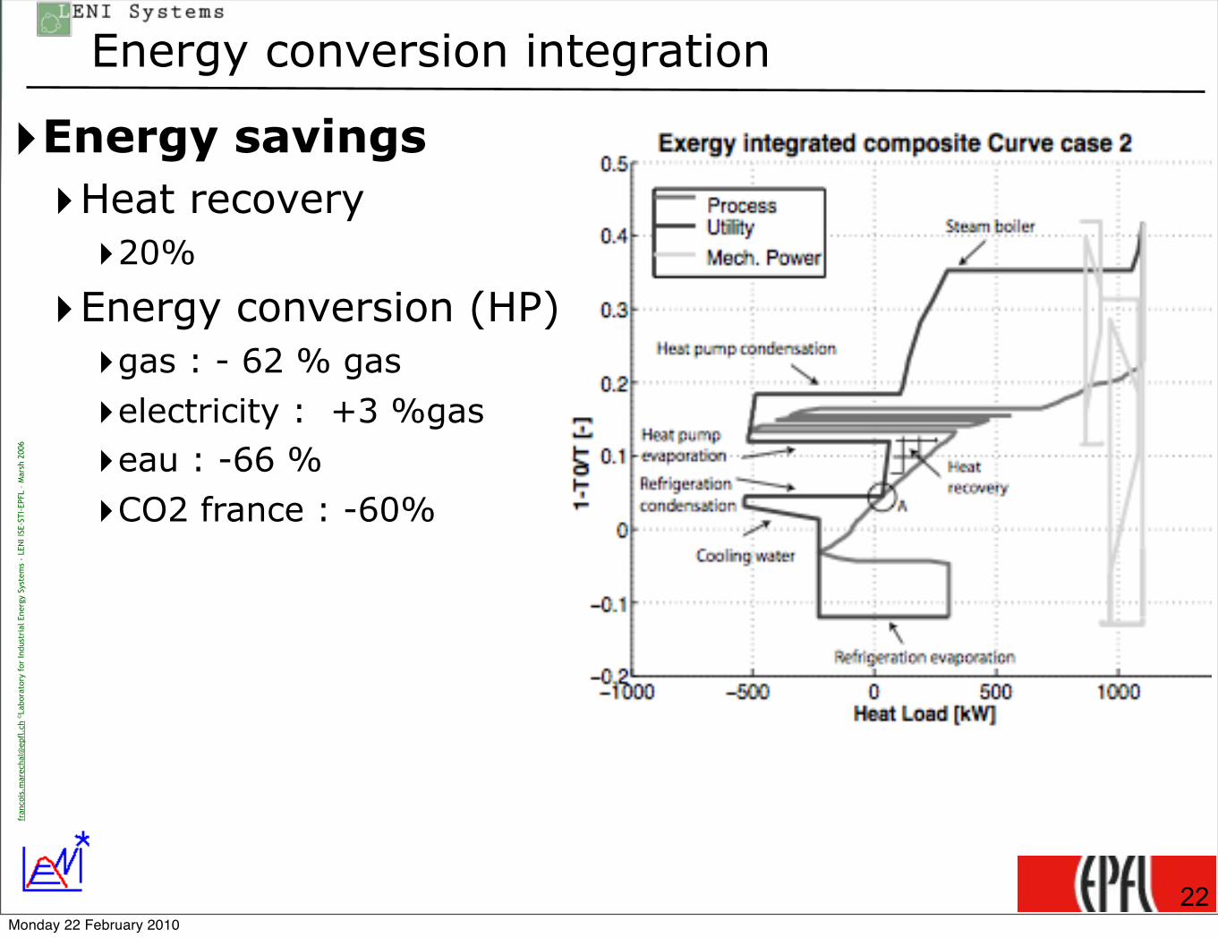
Energy conversion integration
‣Energy savings‣Heat recovery‣20%
‣Energy conversion (HP)‣gas : - 62 % gas
‣electricity : +3 %gas
‣eau : -66 %
‣CO2 france : -60%
22Monday 22 February 2010
![The Linked Data Visualization Modelsvn.aksw.org/papers/2012/ISWC_Visualization/public.pdf · Chi’s Data State Reference Model [5] defines the visualization process in a genericway.Itdescribesaprocessfortransformingrawdataintoaconcretevi-](https://static.fdocuments.us/doc/165x107/5edf5b8dad6a402d666ab52d/the-linked-data-visualization-chias-data-state-reference-model-5-deines-the.jpg)