
ENERGY - einforeach.com PDF (05_07)/BEM05/03_BEM Ju… · Reference should be made to the MS...
52
ENERGY ENERGY KDN PP11720/1/2006 ISSN 0128-4347 VOL.26 JUNE-AUGUST 2005 RM10.00 LEMBAGA JURUTERA MALAYSIA BOARD OF ENGINEERS MALAYSIA LEMBAGA JURUTERA MALAYSIA
Transcript of ENERGY - einforeach.com PDF (05_07)/BEM05/03_BEM Ju… · Reference should be made to the MS...

ENERGYENERGY
KDN PP11720/1/2006 ISSN 0128-4347 VOL.26 JUNE-AUGUST 2005 RM10.00
LE
MB
AG
A
JU
RU
TE
RA
M A L AY S I A
BOARD OF ENGINEERS MALAYSIALEMBAGA JURUTERA MALAYSIA
cont
ents
Volu
me
26
June
- A
ugus
t 20
05
LE
MB
AG
A
JU
RU
TE
RA
M A L AY S I A
29
56
4 President’s MessageEditor’s Note
6 Announcement
Cover Feature7 Low Energy Building in Putrajaya, Malaysia
14 Tsunamis – Dynamics Of Wave EnergyPropagation And Mitigation Measures
21 Earthquake Induced Energy: Sources AndHazard Analysis For Structural EarthquakeResistant Design In Peninsular Malaysia
26 Pilot Centralized Solar Power Station InRemote Village, Rompin, Pahang
Guideline31 Code Of Professional Conduct
Update33 Policy On The Use Of Water Related Products
Engineering & Law34 Instructions & Variations - Part 1
Feature40 Malaysia Energy Supply Industry:
Unique Roles Of Energy Commission
44 Clean Development Mechanism In Malaysia
48 The Coming Of Eurocodes
Engineering Nostalgia56 That which was in 1945……
16
10
2T H E I N G E N I E U R
Seminar On
Pg 5PROFESSIONAL
INDEMNITY INSURANCE

Members of the Board of Engineers Malaysia(BEM) 2004/2005
PresidentYBhg. Tan Sri Dato’ Ir. Hj. Zaini Omar
RegistrarIr. Dr. Mohd Johari Mohd Arif
SecretaryIr. Dr. Judin Abdul Karim
Members of BEMYBhg. Tan Sri Dato’ Ir. Md Radzi Mansor
YBhg. Datuk Ir. Md Sidek AhmadYBhg. Datuk Ir. Hj. Keizrul Abdullah
YBhg. Mej. Jen. Dato’ Ir. Ismail SamionYBhg. Datuk Ir. Santhakumar Sivasubramaniam
YBhg. Datu Ir. Hubert Thian Chong HuiYBhg. Dato’ Ir. Ashok Kumar SharmaYBhg. Dato’ Ir. Abdul Rashid MaidinIr. Prof. Abang Abdullah Abang Ali
Ir. Prof. Dr. Mohd Ali HashimIr. Prof. Dr. Ruslan HassanIr. Ishak Abdul RahmanTuan Hj. Basar Juraimi
Ar. Paul Lai ChuIr. Ho Jin WahIr. P E Chong
Editorial Board
AdvisorYBhg. Tan Sri Dato’ Ir. Hj. Zaini Omar
ChairmanYBhg Datuk Ir. Shanthakumar Sivasubramaniam
EditorIr. Fong Tian Yong
MembersIr. Mustaza SalimIr. Chan Boon Teik
Ir. Ishak Abdul RahmanIr. Prof. Dr. K. S. Kannan
Ir. Prof. Dr. Ruslan HassanIr. Prof. Madya Dr. Eric K H Goh
Ir. Nitchiananthan BalasubramaniamIr. Shahkander Singh
Ir. Prem Kumar
Executive DirectorIr. Ashari Mohd Yakub
Publication OfficerPn. Nik Kamaliah Nik Abdul Rahman
Assistant Publication OfficerPn. Che Asiah Mohamad Ali
Design and ProductionInforeach Communications Sdn Bhd
Buletin Ingenieur is published by the Board ofEngineers Malaysia (Lembaga Jurutera Malaysia)
and is distributed free of charge to registeredProfessional Engineers.
The statements and opinions expressed in thispublication are those of the writers.
BEM invites all registered engineers to contributearticles or send their views and comments to the
following address:
Publication CommitteeLembaga Jurutera Malaysia,Tingkat 17, Ibu Pejabat JKR,
Jalan Sultan Salahuddin,50580 Kuala Lumpur.
Tel: 03-2698 0590 Fax: 03-2692 5017E-mail: [email protected] [email protected]
Web site: http://www.bem.org.my
Advertising/SubscriptionsSubscription Form is on page 54
Advertisement Form is on page 55
Economic development in developing countriesrequires ready access to energy as increasingurbanisation and industrialisation both create greaterdemands for energy. This situation is highly reflectiveof ASEAN as these trends characterize most of thecountries in the region since 1980s. During the sameperiod, energy modelling systems revealed thateconomic growth could be maintained in conjunctionwith significantly slower growth in energy supply –
meaning both these growth can be decoupled.Energy consumption in buildings can be considerably reduced through
integrated building design (with the co-operation of engineers, architectsand equipment suppliers) of new buildings and proper maintenance of existingbuildings. Reference should be made to the MS 1525:2001 Code of Practiceon Energy Efficiency and the Use of Renewable Energy for Non ResidentialBuildings which was developed to encourage the design of new and existingbuildings so that they may be constructed, operated and maintained in amanner that reduces the use of energy without constraining the buildingfunction, nor the comfort or productivity of the occupants and withappropriate regard for cost considerations. The Low Energy Office (LEO)building of the Ministry of Energy, Water and Communications in Putrajayais a demonstration of the application of MS 1525 and serves as a showcasebuilding that exhibits readily available energy efficient and cost effectivefeatures that can be replicated by other buildings.
Engineers should be well versed with the MS 1525 and work as a teamtogether with architects, contractors, interior decorators and equipmentsuppliers to design energy efficient buildings not only to reduce energyconsumption but also to reduce impact on the environment caused by powergeneration.
TAN SRI DATO’ Ir. HJ. ZAINI BIN OMARPresidentBOARD OF ENGINEERS MALAYSIA
President’s Message
Editor’s NoteEngineers may have harnessed many and varied forms
of energy for the benefit of the mankind, but there are stilluntamed natural energies that are yet to be fully understood.This issue attempts to cover a wider range of these forms ofenergy, such as tsunami, lighting and ocean wave, as well asthe efficient use of energy and matters of policy that, wehope, will be of interest to our readers.
On the Engineering Nostalgia front, we are very pleased, and thankful,to receive some collection of old photos from a Village Development Officerin Bentong on behalf the headman of Sri Telemong village in Pahang. Theobjects depicted in the photos may be simple but they certainly evoke theatmosphere and environment of an unsettled period.
We hope you, our readers, will enjoy this issue and we look forward tomore contributions from you.
Ir. Fong Tian YongEditor
KDN PP11720/1/2006ISSN 0128-4347
VOL. 26 JUNE-AUGUST 2005
4T H E I N G E N I E U R

T H E I N G E N I E U R
Name: ……………………………….................................………………...............................................……...
Organisation: ………….......................................................................….
Position: ………………………….................….… Profession: ……………….................................……………
* Registered Engineer (BEM Reg. No.: ………............................…… )
* Others
*Please tick � where applicable
Address: ……..........................………………………………………...........................................
……………………………………………..................................................................................................……..
Tel. No: …………………................................….. Fax No: ………..............................……..................………
E-mail : ………………………………........................................……………
PAYMENT
Cheque/Money Order/Bank Draft No: ……………….…… (Payable to “Lembaga Jurutera Malaysia”)
Amount: ………………………………
Date: ………….................…. Signature: ………..................……………….
Please return the completed form to: LEMBAGA JURUTERA MALAYSIA
17th Floor, Ibu Pejabat JKR, Kompleks Kerja Raya Malaysia,
Jalan Sultan Salahuddin, 50580 Kuala Lumpur
Seminar OnPROFESSIONAL INDEMNITY INSURANCE
BOARD OF ENGINEERS MALAYSIA
LEMBAGA JURUTERA MALAYSIA
Objectives
� To create awareness on the concept and
practice of Professional Indemnity Insurance
in the engineering consultancy industry.
� To gather feedback and comments from
practising engineers on the advantages and
disadvantages of Professional Indemnity
Insurance coverage for professional
engineering services.
Fee
RM100.00: Registered Engineer
RM300.00: Others
(Registration fee includes a set of seminar papers,
lunch and tea)
LE
MB
AG
A
JU
RU
TE
RA
M A L AY S I A
Cancellation/refund: No refund will be made but substitute
participant is allowed. Please inform the BEM Secretariat
in advance of substitution.
CPD
8 hours subject to full attendance
(Professional Engineers only)
Enquiries
Please contact the Board of Engineers Malaysia Secretariat
for more information:
Telephone: 03-26967095/96/97/98, 03-26912090
Fax : 03-26925017
E-Mail: [email protected], [email protected]
Closing date for registration: 14th July 2005
R E G I S T R A T I O N F O R M
✁
5
28th July 2005
THE SAUJANA, KUALA LUMPUR
2 km Off Jln Sultan Abdul Aziz Shah, Airport Highway, Subang, 47200 Subang, Selangor
(Formerly known as Hyatt Regency Saujana Subang)
Organised By

Announcement
PublicationCalendar
The following list is the Publication Calendar for theyear 2005. While we normally seek contributions fromexperts for each special theme, we are also pleased toaccept articles relevant to themes listed.
Please contact the Editor or the Publication Officer inadvance if you would like to make such contributionsor to discuss details and deadlines.
September 2005: WASTEDecember 2005: WATERMarch 2006: ENGINEERING PRACTICEJune 2006: MINERALS
T H E I N G E N I E U R
By Ole Balslev-Olesen, Steve Lojuntin, CK. Tang, K.S. Kannan,DANIDA (Danish International Development Assistance) Renewable Energy and Energy Efficiency, Malaysia.
In September 2004, the Ministryof Energy, Water &Communications (MEWC) moved
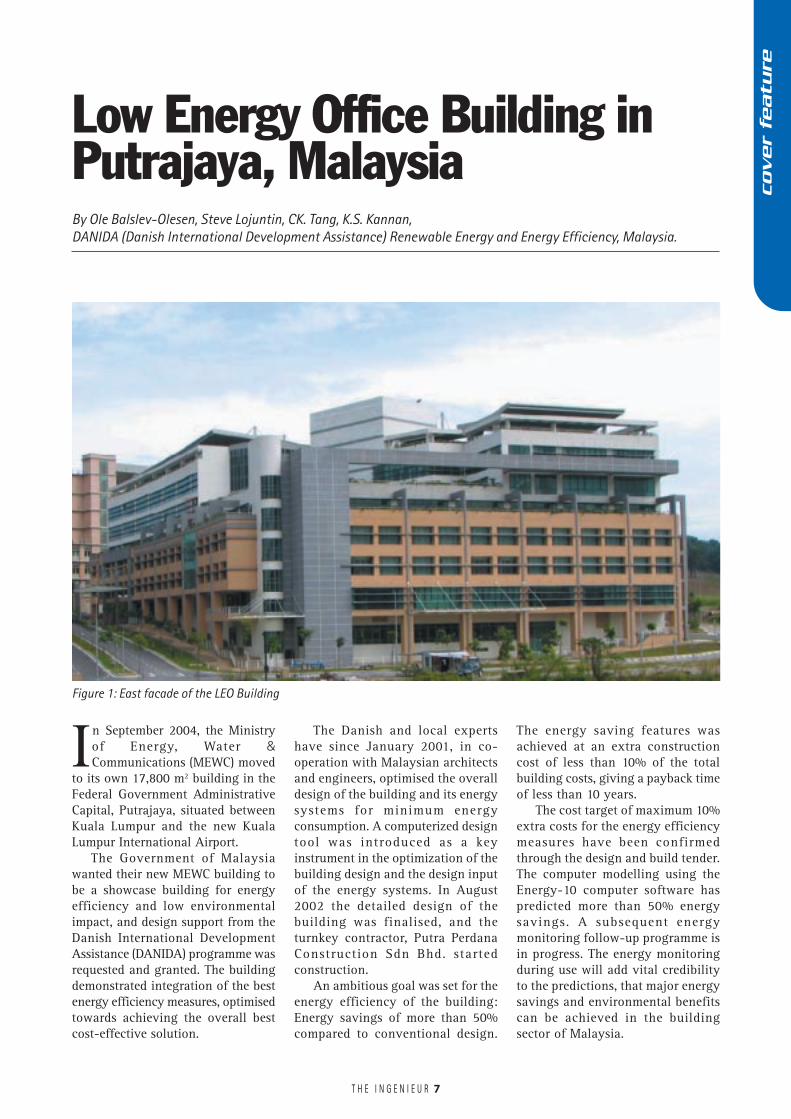
to its own 17,800 m2 building in theFederal Government AdministrativeCapital, Putrajaya, situated betweenKuala Lumpur and the new KualaLumpur International Airport.
The Government of Malaysiawanted their new MEWC building tobe a showcase building for energyefficiency and low environmentalimpact, and design support from theDanish International DevelopmentAssistance (DANIDA) programme wasrequested and granted. The buildingdemonstrated integration of the bestenergy efficiency measures, optimisedtowards achieving the overall bestcost-effective solution.
The Danish and local expertshave since January 2001, in co-operation with Malaysian architectsand engineers, optimised the overalldesign of the building and its energysystems for minimum energyconsumption. A computerized designtool was introduced as a keyinstrument in the optimization of thebuilding design and the design inputof the energy systems. In August2002 the detailed design of thebuilding was finalised, and theturnkey contractor, Putra PerdanaConstruction Sdn Bhd. startedconstruction.
An ambitious goal was set for theenergy efficiency of the building:Energy savings of more than 50%compared to conventional design.
7
The energy saving features wasachieved at an extra constructioncost of less than 10% of the totalbuilding costs, giving a payback timeof less than 10 years.
The cost target of maximum 10%extra costs for the energy efficiencymeasures have been confirmedthrough the design and build tender.The computer modelling using theEnergy-10 computer software haspredicted more than 50% energysavings. A subsequent energymonitoring follow-up programme isin progress. The energy monitoringduring use will add vital credibilityto the predictions, that major energysavings and environmental benefitscan be achieved in the buildingsector of Malaysia.
Low Energy Office Building inPutrajaya, Malaysia
Figure 1: East facade of the LEO Building
cover
featu
re
T H E I N G E N I E U R
The new MEWC LEO building(Figure 1) demonstrates the feasibilityof the energy efficiency measuresaccording to the new MalaysianStandard MS 1525:2001 “Code ofPractice on Energy Efficiency and useof Renewable Energy for Non-residential Buildings”. Following thiscode, the LEO building must have anenergy consumption less than 135kWh/m2 year. The predictions are, thatthe LEO building will have an energyindex close to 100 kWh/m2 year. Thisis a very good performance comparedto typical new office buildings inMalaysia and the ASEAN region,having an Energy Index of 200–300kWh/m2 year. The energy index iscurrently being continuouslymonitored.
The energy efficiency measuresthat contribute to achieving the goalof an Energy Index of 100 kWh/m2
year are:� Creation of a green environment
around and on top of the building.� Optimisation of building
orientation, with preference tosouth and north facing windows,where solar heat is less than forother orientations.
� Energy efficient space planning.� A well insulated building facade
and building roof.� Protection of windows from direct
sunshine and protection of theroof by a double roof
� Natural ventilation in the atrium� Energy efficient cooling system,
where the air volume for eachbuilding zone is controlledindividually according to demand
� Maximise use of diffuse daylightand use of high efficiency lighting,controlled according to daylightavailability and occupancy
� Energy efficient office equipment(less electricity use and lesscooling demand )
� Implementation of an EnergyManagement System, where theperformances of the climaticsystems are continuouslyoptimised to meet optimal comfortcriteria at least energy costs
Building Characteristics
The climate in Malaysia is hot andhumid. Temperatures over the yearand day varies typically between 24oCand 35oC, and the humidity is high.This has important implications forthe design of modern energy efficient,air conditioned office buildings. In theoffice working areas, a controlled,conducive environment is essentialfor occupant comfort and forproductive output.
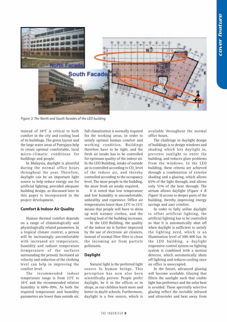
In the LEO Building, the windowsare primarily orientated to the Northand the South (Figure 3). Thisorientation receives less directsunshine, and only shallow out
8
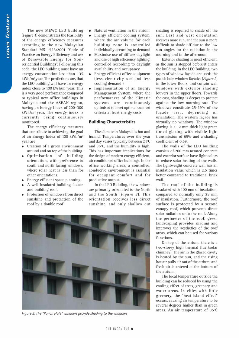
Figure 2: The “Punch Hole” windows provide shading to the windows
shading is required to shade off thesun. East and west orientationreceives more sun, and the sun is moredifficult to shade off due to the lowsun angles for the radiation in themorning and in the afternoon.
Exterior shading is most efficient,as the sun is stopped before it entersthe building. In the LEO Building, twotypes of window façade are used: thepunch hole window facades (Figure 2)in the lower floors, and curtain wallwindows with exterior shadinglouvers in the upper floors. Towardsthe east, shading is deeper to protectagainst the low morning sun. Thewindows constitute 25-39% of thefaçade area, depending onorientation. The western façade hasvirtually no windows. The windowglazing is a 12 mm thick light greentinted glazing with visible lighttransmission of 65% and a shadingcoefficient of 0.59.
The walls of the LEO buildingconsists of 200 mm aerated concreteand exterior surface have light colorsto reduce solar heating of the walls.The lightweight concrete wall has aninsulation value which is 2.5 timesbetter compared to traditional brickwall.
The roof of the building isinsulated with 100 mm of insulation,compared to normally only 25 mmof insulation. Furthermore, the roofsurface is protected by a secondcanopy roof, which prevents directsolar radiation onto the roof. Alongthe perimeter of the roof, greenlandscaping provides shading andimproves the aesthetics of the roofareas, which can be used for variousfunctions.
On top of the atrium, there is atwo-storey high thermal flue (solarchimney). The air in the glazed cavityis heated by the sun, and the risinghot air pulls air out of the atrium, andfresh air is entered at the bottom ofthe atrium.
The local temperature outside thebuilding can be reduced by using thecooling effect of trees, greenery andwater areas. In cities with littlegreenery, the “heat island effect”occurs, causing air temperature to beseveral degrees higher than in greenareas. An air temperature of 35oC
cover
featu
re
T H E I N G E N I E U R 9
available throughout the normaloffice hours.
The challenge in daylight designof buildings is to design windows andshading which lets daylight in,prevents sunlight to enter thebuilding, and reduces glare problemsfrom the windows. In the LEObuilding, these criteria are achievedthrough a combination of exteriorshading and a glazing, which allows65% of the light through, and allowsonly 51% of the heat through. Theatrium allows daylight (Figure 4 &Figure 5) access to deeper parts of thebuilding, thereby improving energysavings and user comfort.
In order to fully utilise daylightto offset artificial lighting, theartificial lighting has to be controlledso that it is automatically shut offwhen daylight is sufficient to satisfythe lighting need, which is anillumination level of 300-400 lux. Inthe LEO building, a daylightresponsive control system on lightingsystem is combined with a motiondetector, which automatically shutsoff lighting and reduces cooling oncean office is unoccupied.
In the future, advanced glazingwill become available. Glazing thatfilters the sunlight such that visiblelight has preference and the solar heatis avoided. These spectrally selectiveglazing reflect the invisible infraredand ultraviolet and heat away from
instead of 28oC is critical to bothcomfort in the city and cooling loadof its buildings. The green layout andthe large water areas of Putrajaya helpto create optimal comfortable, localmicro-climatic conditions forbuildings and people.
In Malaysia, daylight is plentifulduring the normal office hoursthroughout the year. Therefore,daylight can be an important lightsource to help reduce energy use forartificial lighting, provided adequatebuilding design, as discussed later inthis paper is incorporated in theproject development.
Comfort & Indoor Air Quality
Human thermal comfort dependson a range of climatologically andphysiologically related parameters. Ina tropical climate context, a personwill be increasingly uncomfortablewith increased air temperature,humidity and radiant temperature(temperature of the surfacessurrounding the person). Increased airvelocity and reduction of the clothinglevel can help in improving thecomfort level.
The recommended indoortemperature range is from 23oC to26oC and the recommended relativehumidity is 60%-70%. As both therequired temperature and humidityparameters are lower than outside air,
full climatization is normally requiredfor the working areas, in order tosatisfy optimal human comfort andworking condition. Buildingstherefore have to be tight, and thefresh air intake has to be controlledfor optimum quality of the indoor air.In the LEO Building, intake of outsideair is controlled according to CO2 levelof the indoor air, and therebycontrolled according to the occupancylevel. The more people in the building,the more fresh air intake required.
It is noted that low temperatureand low humidity is uncomfortable,unhealthy and expensive. Office airtemperatures lower than 22oC to 23oCmeans that people will have to dressup with warmer clothes, and thecooling load of the building increases.
In the LEO Building, the qualityof the indoor air is further improvedby the use of electronic air cleaners,instead of normal fibre filter to cleanthe incoming air from particlepollutants.
Daylight
Natural light is the preferred lightsource fo human beings. Thisperception has now also beenscientifically proven: People preferdaylight, be it in the offices or inshops, as our children learn more andbetter in daylit schools. Furthermore,daylight is a free source, which is
Figure 3: The North and South facades of the LEO building
cover
featu
re
T H E I N G E N I E U R 10
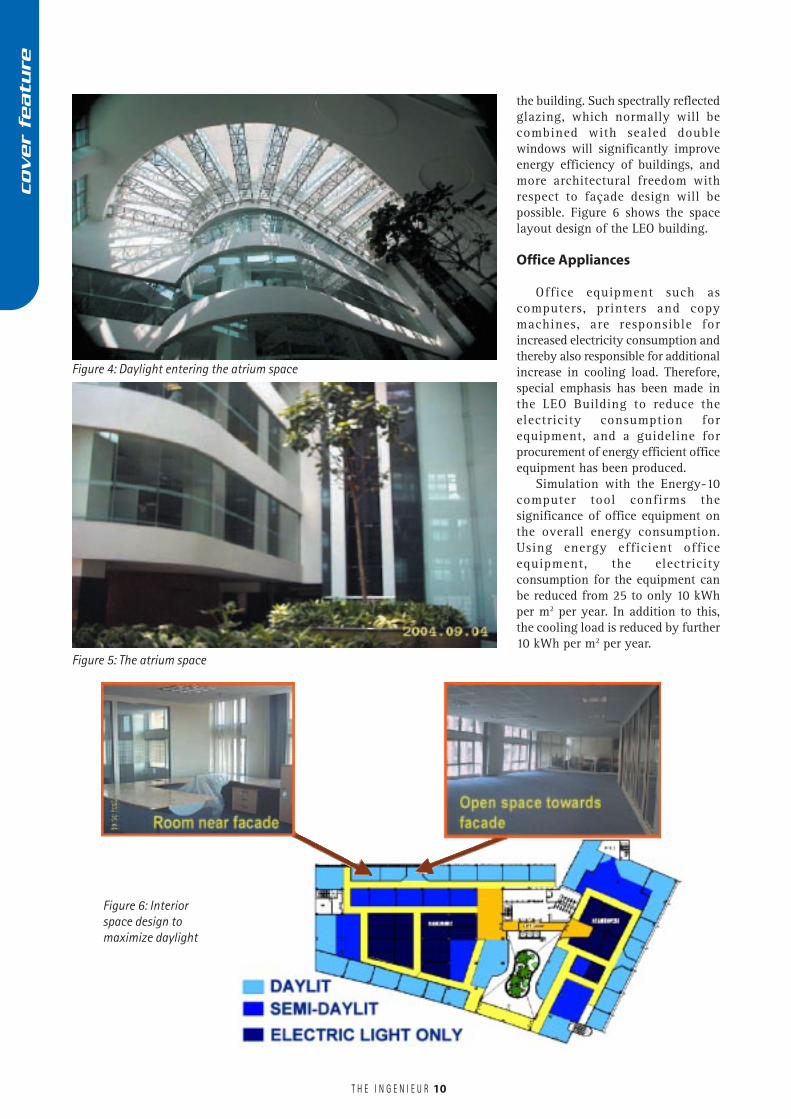
Figure 6: Interiorspace design tomaximize daylight
the building. Such spectrally reflectedglazing, which normally will becombined with sealed doublewindows will significantly improveenergy efficiency of buildings, andmore architectural freedom withrespect to façade design will bepossible. Figure 6 shows the spacelayout design of the LEO building.
Office Appliances
Office equipment such ascomputers, printers and copymachines, are responsible forincreased electricity consumption andthereby also responsible for additionalincrease in cooling load. Therefore,special emphasis has been made inthe LEO Building to reduce theelectricity consumption forequipment, and a guideline forprocurement of energy efficient officeequipment has been produced.
Simulation with the Energy-10computer tool confirms thesignificance of office equipment onthe overall energy consumption.Using energy efficient officeequipment, the electricityconsumption for the equipment canbe reduced from 25 to only 10 kWhper m2 per year. In addition to this,the cooling load is reduced by further10 kWh per m2 per year.
Figure 5: The atrium space
Figure 4: Daylight entering the atrium space
cover
featu
re
T H E I N G E N I E U R 11
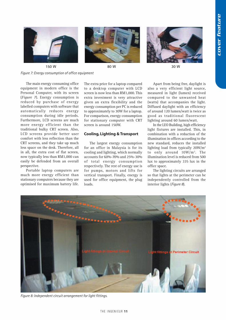
The main energy consuming officeequipment in modern office is thePersonal Computer, with its screen(Figure 7). Energy consumption isreduced by purchase of energylabelled computers with software thatautomatically reduces energyconsumption during idle periods.Furthermore, LCD screens are muchmore energy efficient than thetraditional bulky CRT screen. Also,LCD screens provide better usercomfort with less reflection than theCRT screens, and they take up muchless space on the desk. Therefore, allin all, the extra cost of flat screen,now typically less than RM1,000 caneasily be defended from an overallperspective.
Portable laptop computers aremuch more energy efficient thanstationary computers because they areoptimised for maximum battery life.
150 W 80 W 30 W
Figure 7: Energy consumption of office equipment
The extra price for a laptop comparedto a desktop computer with LCDscreen is now less than RM1,000. Thisextra investment is very attractivegiven an extra flexibility and theenergy consumption per PC is reducedto approximately to 30W for a laptop.For comparison, energy consumptionfor stationary computer with CRTscreen is around 150W.
Cooling, Lighting & Transport
The largest energy consumptionfor an office in Malaysia is for itscooling and lighting, which normallyaccounts for 60%-70% and 25%-30%of total energy consumptionrespectively. The rest of energy use isfor pumps, motors and lifts forvertical transport. Finally, energy isused for office equipment, the plugloads.
Apart from being free, daylight isalso a very efficient light source,measured in light (lumen) receivedcompared to the unwanted heat(watts) that accompanies the light.Diffused daylight with an efficiencyof around 120 lumen/watt is twice asgood as traditional fluorescentlighting around 60 lumen/watt.
In the LEO Building, high efficiencylight fixtures are installed. This, incombination with a reduction of theillumination in offices according to thenew standard, reduces the installedlighting load from typically 20W/m2
to only around 10W/m2. Theillumination level is reduced from 500lux to approximately 335 lux in theoffice space.
The lighting circuits are arrangedso that lights at the perimeter can beindependently controlled from theinterior lights (Figure 8).
Figure 8: Independent circuit arrangement for light fittings.
cover
featu
re
T H E I N G E N I E U R
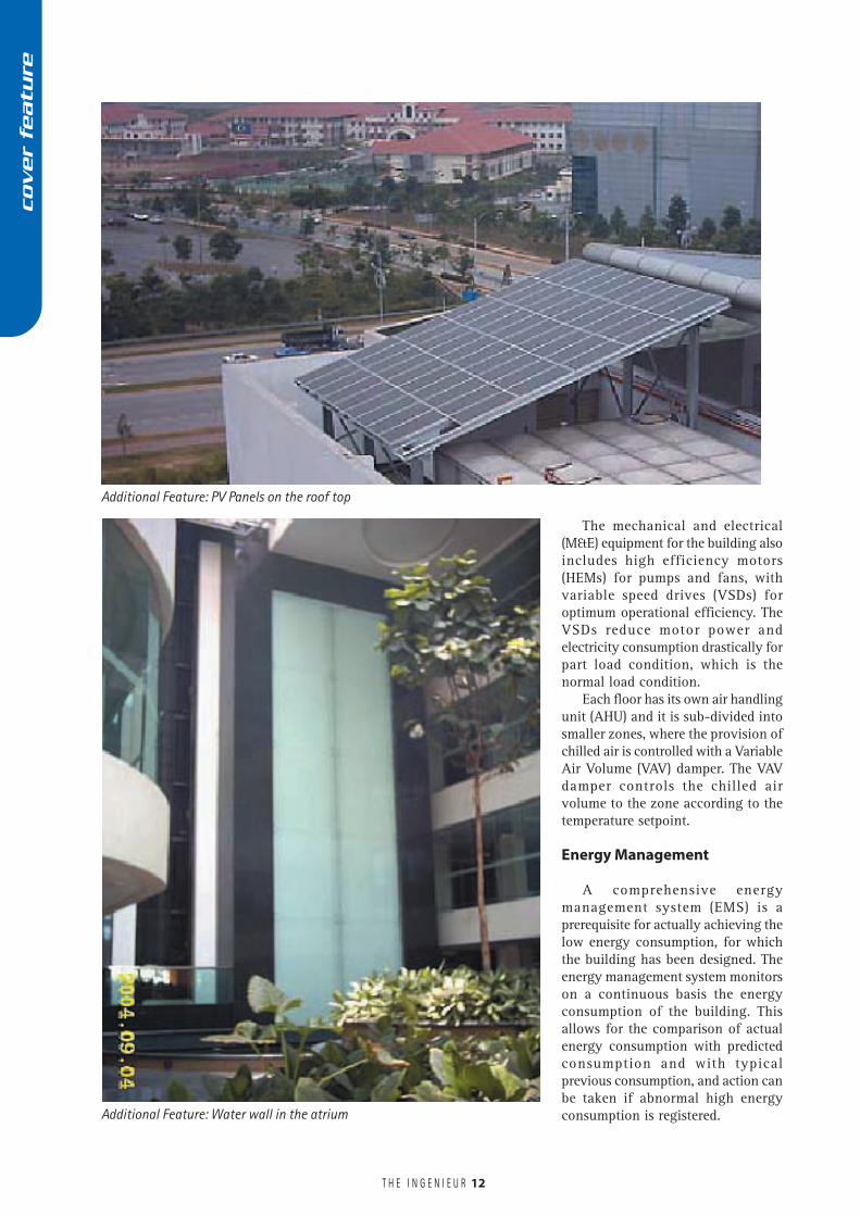
The mechanical and electrical(M&E) equipment for the building alsoincludes high efficiency motors(HEMs) for pumps and fans, withvariable speed drives (VSDs) foroptimum operational efficiency. TheVSDs reduce motor power andelectricity consumption drastically forpart load condition, which is thenormal load condition.
Each floor has its own air handlingunit (AHU) and it is sub-divided intosmaller zones, where the provision ofchilled air is controlled with a VariableAir Volume (VAV) damper. The VAVdamper controls the chilled airvolume to the zone according to thetemperature setpoint.
Energy Management
A comprehensive energymanagement system (EMS) is aprerequisite for actually achieving thelow energy consumption, for whichthe building has been designed. Theenergy management system monitorson a continuous basis the energyconsumption of the building. Thisallows for the comparison of actualenergy consumption with predictedconsumption and with typicalprevious consumption, and action canbe taken if abnormal high energyconsumption is registered.
12
Additional Feature: PV Panels on the roof top
Additional Feature: Water wall in the atrium
cover
featu
re
T H E I N G E N I E U R
Energy management requires theinstallation of adequate metering as ameans of measuring the energy used.As the saying goes “you cannot managewhat you cannot measure”. In addition,the EMS shall incorporate a computersoftware tool, which helps the buildingenergy management to optimise theperformance of various energy systemsfor cooling and lighting, such thatoptimal user comfort is achieved at leastcost in purchase of energy.
The LEO Building will be equippedwith a comprehensive EnergyManagement System. For each floorand each section (east or west wing),energy consumption for cooling,lighting and plug loads is monitoredindividually. Furthermore, temperaturesin various parts of the zone aremonitored. The detailed monitoringdata of the LEO building will be madeavailable for further study by academiaand professionals.
Successful energy management canonly be achieved if there is a competentenergy management authority inaddition to the traditional buildingmanagement services. The Ministry hastherefore created a special position forenergy manager. He will be responsiblefor the day-to-day energy managementactivities including advising theorganisation related on energymanagement activities.
Conclusion
The use of computer design toolsmeans that an overall optimisation ofthe building energy design can becarried out at the drawing table. Extracosts for some energy saving buildingelements can be offset by reducedcosts for other elements, such asreduced investment costs for thecooling system caused by a moreefficient building envelope, thatreduces the maximum cooling load.Furthermore, using life cyclecalculations, extra costs for energysaving features can be offset bysavings in energy costs over the lifecycle of the building.
The LEO Building has beenoptimised using the Energy-10computer software from NationalRenewable Energy Laboratory, DenverUS. Among the many computerdesign tools available, Energy-10 waschosen, as it is very user-friendly, yetsophisticated, calculating the energybalance of the building hour by hourthroughout a year.
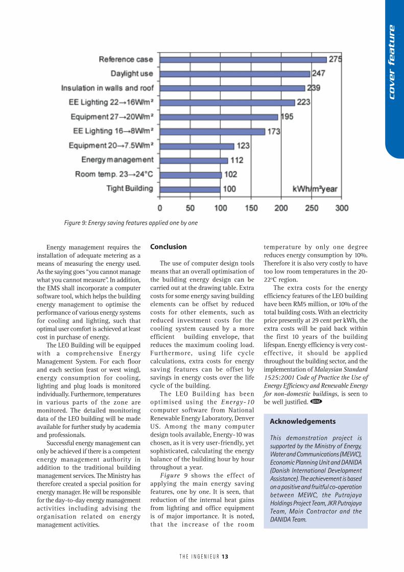
Figure 9 shows the effect ofapplying the main energy savingfeatures, one by one. It is seen, thatreduction of the internal heat gainsfrom lighting and office equipmentis of major importance. It is noted,that the increase of the room
temperature by only one degreereduces energy consumption by 10%.Therefore it is also very costly to havetoo low room temperatures in the 20-22oC region.
The extra costs for the energyefficiency features of the LEO buildinghave been RM5 million, or 10% of thetotal building costs. With an electricityprice presently at 29 cent per kWh, theextra costs will be paid back withinthe first 10 years of the buildinglifespan. Energy efficiency is very cost-effective, it should be appliedthroughout the building sector, and theimplementation of Malaysian Standard1525:2001 Code of Practice the Use ofEnergy Efficiency and Renewable Energyfor non-domestic buildings, is seen tobe well justified.
Figure 9: Energy saving features applied one by one
BEM
Acknowledgements
This demonstration project issupported by the Ministry of Energy,Water and Communications (MEWC),Economic Planning Unit and DANIDA(Danish International DevelopmentAssistance). The achievement is basedon a positive and fruitful co-operationbetween MEWC, the PutrajayaHoldings Project Team, JKR PutrajayaTeam, Main Contractor and theDANIDA Team.
13
cover
featu
re
T H E I N G E N I E U R
Tsunamis – Dynamics OfWave Energy PropagationAnd Mitigation MeasuresBy Prof. Madya Ir. Dr. Eric Goh, Head - AMQUEST RESEARCH, USM Engineering Campus, Universiti Sains Malaysia,Prof. Dr. Koh Hock Lye, Chairman - ECOMOD, School of Mathematical Sciences, Universiti Sains Malaysia
14
Tsunamis are formed due to thedisruption of any body of watercaused by the sudden
displacement of the seafloor.Earthquakes, submarine landslides,volcanic eruptions or even meteoriteimpacts may cause tsunamis. Alloceanic regions of the world aresubjected to the threat of tsunamis;however, tsunamis are concentratedin the Pacific oceans and its marginalseas. Tsunami is thus basically awaveform that originates from deepwater, typically more than 1000m; butas a wave travels towards the shore;its wavelength is progressivelyreduced, while the wave heights maybe progressively increased. Thetsunami that devastated the shorelinesof 11 countries on December 26, 2004,was triggered by a mega-thrustearthquake with a high magnitude ofnine on the Richter scale making itthe most powerful for the past 40years (CNN, 2005). Mega-thrustearthquakes are a potentially verydestructive type caused when atectonic plate in the Earth’s crust slipsunder another one. The last highesttoll for an earthquake-tsunamicombination took place on December
Tsunamis have received increased global public attention due to therecent outcome of the Asian Tsunami Disaster that has affected thelives of millions of people around the world combined with a shockingdeath toll of over 280,000 inhabitants (AFP, 2005). This is greatly dueto their perilous wave energy and extensive destruction caused onimpact upon reaching coastal areas. The United Nations had to mobilisethe world’s largest relief operation spanning several countries borderingthe Indian Ocean to accommodate all the nations affected by thissingle energy-intensive natural occurrence. The destruction arising fromthe recent tsunami incident is phenomenal. Statistics of lives lost andmillions affected round the world are just numbers, however several ofus engineers unfortunately could put faces to some of the statisticspresented on the news. One of the authors’ closest colleagues whomthe authors had the opportunity to work with under the internationalresearch exchange programme is Doctorandus (Drs.) Junaidi, a veryefficient and pro-active academic, based at Syiah Kuala University -Banda Aceh. Till today the authors are still optimistic, and will continueto hope for the best, since he and his family have been classified onlyas ‘missing’. As responsible engineers, the authors wish to put onrecord our sincere sympathies to all those affected by the Asian TsunamiDisaster as the trauma and pain of all those directly and indirectlyaffected by this recent calamity is beyond comprehension. This featurehighlights the causes of tsunamis, the disastrous energy unleashed bynature and their impact; supplemented by engineering innovationsfor successful early warning detection and proposed mitigationsmeasures to minimise the possible loss of lives and property againstfuture potential occurrences.
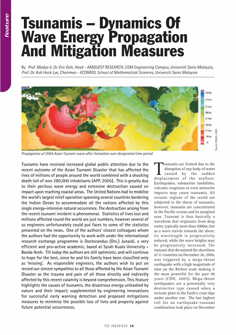
Propagation of 2004 Asian Tsunami wave after formation over designated time period
Sour
ce: N
OAA,
200
5
featu
re
T H E I N G E N I E U R 15
28, 1908, when a 7.2 magnitudequake struck Messina, Italy, killing anestimated 70,000 to 100,000inhabitants. A 7.8 magnitudeearthquake near Alaska generated themost destructive tsunami in 1946.The 35m height waves causedextensive damage in the neighbouringHawaiian Islands.
Initiation and Dynamics of TsunamiWave Propagation
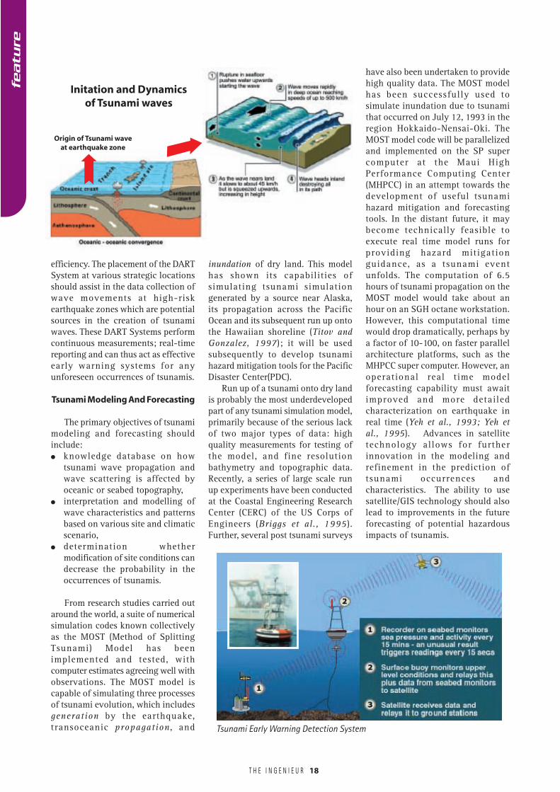
A tsunami comprises a series ofwaves of extremely long periods andwavelengths and is generated in abody of water by an impulsive orrapid vertical disturbance of the seafloor. A tsunami is formed when theseafloor is suddenly raised or lowereddue to a violent earthquake. Thepotential kinetic energy that resultsfrom pushing water above mean sealevel is then transferred to theinitiation for the propagation of thetsunami wave. The most destructivetsunamis are formed from theoccurrence of large earthquakes in
deep waters with an epicentre or faultline near or on the ocean floor. Theseusually occur in regions of the earthcharacterized by high geologicalactivities due to the collision of theplates along tectonic plate boundaries.A tsunami can have a period rangingbetween 10 minutes and one hour anda wavelength in excess of 700 km.The term tsunami, meaning harbourwave in Japanese, was adopted forgeneral use in 1963.
The recent December 26th AsianTsunami Disaster was due to thedisplacement of water caused by anundersea earthquake, with a highmagnitude of nine on the Richterscale, arose from the slippage of theAustralian and Eurasian plates 160km centred off the west coast ofSumatra, Indonesia at a depth of 10km (BBC, 2005). Rapid underwatershift between the two tectonic plates,resulting in the seafloor being shuntedvertically by 10-30m at the site of therupture, created a violent reaction inthe displacement of seawater from theequilibrium position.
The main criterion that determinesthe size of the tsunami wave is theamount of vertical sea floordisplacement. Not all earthquakesproduce tsunamis. No destructivetsunami was however observed onMarch 29, 2005 (though tremors werefelt in Kuala Lumpur, Petaling Jaya,Klang, Penang, Ipoh and Melaka)during the recent powerful earthquakemeasuring a high of 8.5 on the Richterscale with its epicentre off the westcoast of Sumatra (The Sun, 2005). TheMarch 29, 2005 event did not createany tsunamis because the recentearthquake originated in shallowwaters. Earthquakes must occur neardeep-seated ocean floor and of a largeenough magnitude to createmovements on the sea floor for thedevelopment of tsunamis.
The December 26, 2004earthquake incident off the coast ofSumatra displaced millions of litresof overlaying seawater resulting in theformation of a massive tsunami (CNN,2005). Upon formation, the tsunamihigh-energy wave then fans out in
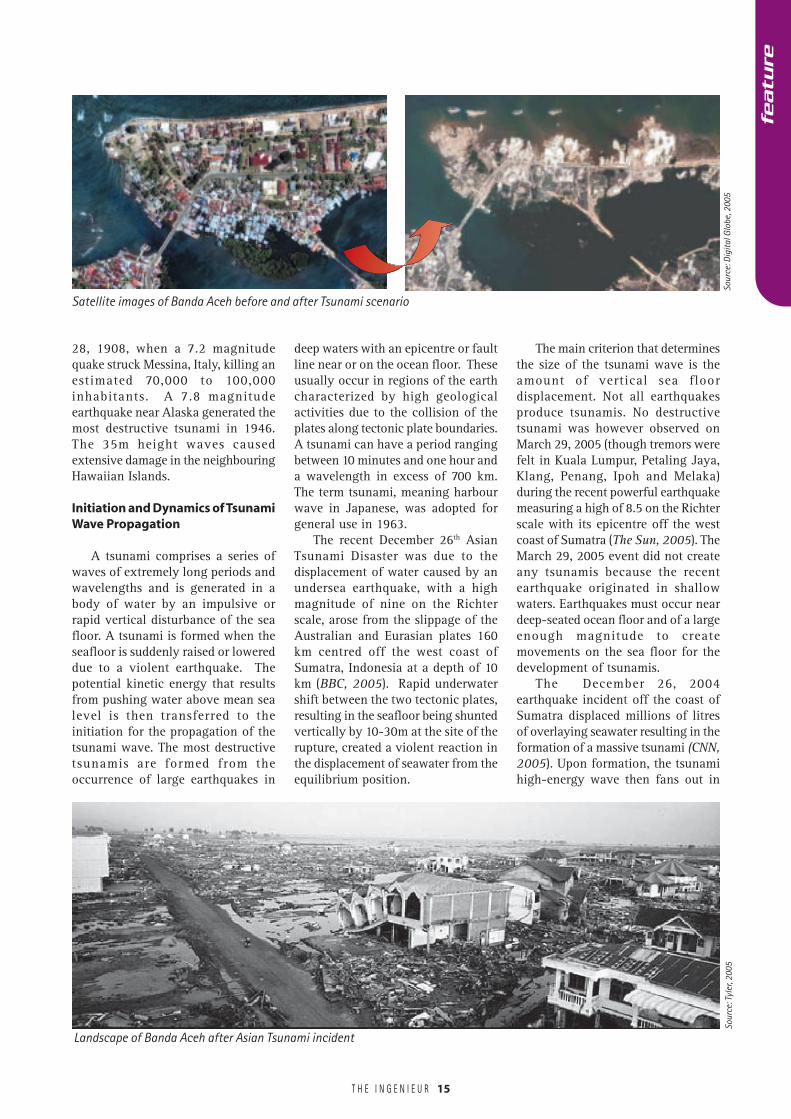
Satellite images of Banda Aceh before and after Tsunami scenario
Landscape of Banda Aceh after Asian Tsunami incident
Sour
ce: T
yler
, 200
5
featu
re
Sour
ce: D
igita
l Glo
be, 2
005
T H E I N G E N I E U R 16
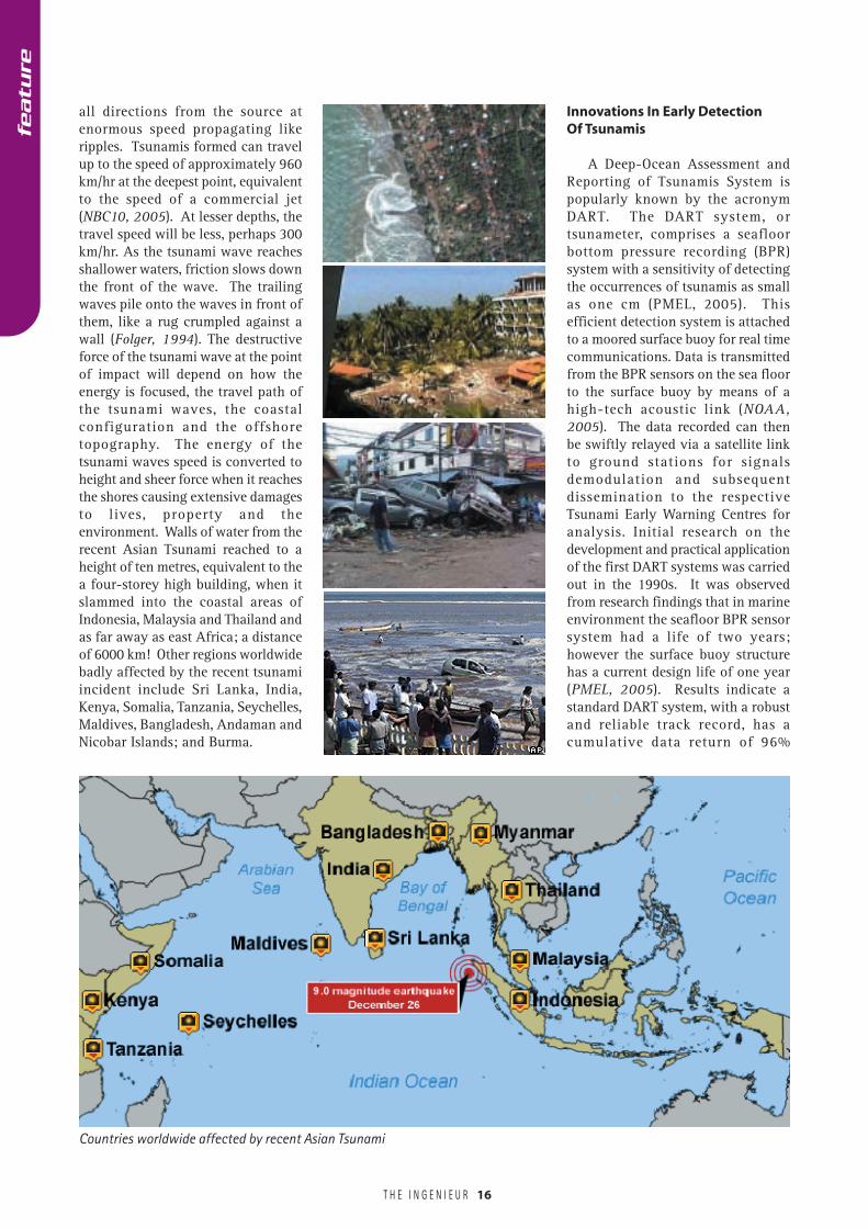
all directions from the source atenormous speed propagating likeripples. Tsunamis formed can travelup to the speed of approximately 960km/hr at the deepest point, equivalentto the speed of a commercial jet(NBC10, 2005). At lesser depths, thetravel speed will be less, perhaps 300km/hr. As the tsunami wave reachesshallower waters, friction slows downthe front of the wave. The trailingwaves pile onto the waves in front ofthem, like a rug crumpled against awall (Folger, 1994). The destructiveforce of the tsunami wave at the pointof impact will depend on how theenergy is focused, the travel path ofthe tsunami waves, the coastalconfiguration and the offshoretopography. The energy of thetsunami waves speed is converted toheight and sheer force when it reachesthe shores causing extensive damagesto lives, property and theenvironment. Walls of water from therecent Asian Tsunami reached to aheight of ten metres, equivalent to thea four-storey high building, when itslammed into the coastal areas ofIndonesia, Malaysia and Thailand andas far away as east Africa; a distanceof 6000 km! Other regions worldwidebadly affected by the recent tsunamiincident include Sri Lanka, India,Kenya, Somalia, Tanzania, Seychelles,Maldives, Bangladesh, Andaman andNicobar Islands; and Burma.
Innovations In Early DetectionOf Tsunamis
A Deep-Ocean Assessment andReporting of Tsunamis System ispopularly known by the acronymDART. The DART system, ortsunameter, comprises a seafloorbottom pressure recording (BPR)system with a sensitivity of detectingthe occurrences of tsunamis as smallas one cm (PMEL, 2005). Thisefficient detection system is attachedto a moored surface buoy for real timecommunications. Data is transmittedfrom the BPR sensors on the sea floorto the surface buoy by means of ahigh-tech acoustic link (NOAA,2005). The data recorded can thenbe swiftly relayed via a satellite linkto ground stations for signalsdemodulation and subsequentdissemination to the respectiveTsunami Early Warning Centres foranalysis. Initial research on thedevelopment and practical applicationof the first DART systems was carriedout in the 1990s. It was observedfrom research findings that in marineenvironment the seafloor BPR sensorsystem had a life of two years;however the surface buoy structurehas a current design life of one year(PMEL, 2005). Results indicate astandard DART system, with a robustand reliable track record, has acumulative data return of 96%
Countries worldwide affected by recent Asian Tsunami
featu
re
T H E I N G E N I E U R
featu
re
18
efficiency. The placement of the DARTSystem at various strategic locationsshould assist in the data collection ofwave movements at high-riskearthquake zones which are potentialsources in the creation of tsunamiwaves. These DART Systems performcontinuous measurements; real-timereporting and can thus act as effectiveearly warning systems for anyunforeseen occurrences of tsunamis.
Tsunami Modeling And Forecasting
The primary objectives of tsunamimodeling and forecasting shouldinclude:� knowledge database on how
tsunami wave propagation andwave scattering is affected byoceanic or seabed topography,
� interpretation and modelling ofwave characteristics and patternsbased on various site and climaticscenario,
� determination whethermodification of site conditions candecrease the probability in theoccurrences of tsunamis.
From research studies carried outaround the world, a suite of numericalsimulation codes known collectivelyas the MOST (Method of SplittingTsunami) Model has beenimplemented and tested, withcomputer estimates agreeing well withobservations. The MOST model iscapable of simulating three processesof tsunami evolution, which includesgeneration by the earthquake,transoceanic propagation , and
inundation of dry land. This modelhas shown its capabilities ofsimulating tsunami simulationgenerated by a source near Alaska,its propagation across the PacificOcean and its subsequent run up ontothe Hawaiian shoreline (Titov andGonzalez, 1997); it will be usedsubsequently to develop tsunamihazard mitigation tools for the PacificDisaster Center(PDC).
Run up of a tsunami onto dry landis probably the most underdevelopedpart of any tsunami simulation model,primarily because of the serious lackof two major types of data: highquality measurements for testing ofthe model, and fine resolutionbathymetry and topographic data.Recently, a series of large scale runup experiments have been conductedat the Coastal Engineering ResearchCenter (CERC) of the US Corps ofEngineers (Briggs et al., 1995).Further, several post tsunami surveys
have also been undertaken to providehigh quality data. The MOST modelhas been successfully used tosimulate inundation due to tsunamithat occurred on July 12, 1993 in theregion Hokkaido-Nensai-Oki. TheMOST model code will be parallelizedand implemented on the SP supercomputer at the Maui HighPerformance Computing Center(MHPCC) in an attempt towards thedevelopment of useful tsunamihazard mitigation and forecastingtools. In the distant future, it maybecome technically feasible toexecute real time model runs forproviding hazard mitigationguidance, as a tsunami eventunfolds. The computation of 6.5hours of tsunami propagation on theMOST model would take about anhour on an SGH octane workstation.However, this computational timewould drop dramatically, perhaps bya factor of 10-100, on faster parallelarchitecture platforms, such as theMHPCC super computer. However, anoperational real time modelforecasting capability must awaitimproved and more detailedcharacterization on earthquake inreal time (Yeh et al., 1993; Yeh etal., 1995). Advances in satellitetechnology allows for furtherinnovation in the modeling andrefinement in the prediction oftsunami occurrences andcharacteristics. The ability to usesatellite/GIS technology should alsolead to improvements in the futureforecasting of potential hazardousimpacts of tsunamis.
Initation and Dynamicsof Tsunami waves
Origin of Tsunami waveat earthquake zone
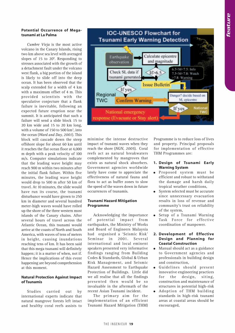
Tsunami Early Warning Detection System
T H E I N G E N I E U R
featu
re
19
Potential Occurrence of Mega-tsunami at La Palma
Cumbre Vieja is the most activevolcano in the Canary Islands, risingtwo km above sea level with averagedslopes of 15 to 200. Responding tostresses associated with the growth ofa detachment fault under the volcanowest flank, a big portion of the islandis likely to slide off into the deepocean. It has been observed that thescalp extended for a width of 4 kmwith a maximum offset of 4 m. Thisprovided scientists with thespeculative conjecture that a flankfailure is inevitable, following anexpected future eruption near thesummit. It is anticipated that such afailure will send a slide block 15 to20 km wide and 15 to 20 km long,with a volume of 150 to 500 km3, intothe ocean (Ward and Day, 2001). Thisblock will cascade down the steepoffshore slope for about 60 km untilit reaches the flat ocean floor at 4,000m depth with a peak velocity of 100m/s. Computer simulations indicatethat the leading wave height mayreach 900 m within two minutes afterthe initial flank failure. Within fiveminutes, the leading wave heightwould drop to 500 m after 50 km oftravel. At 10 minutes, the slide wouldhave run its course, the tsunamidisturbance would have grown to 250km in diameter and several hundredmeter-high waves would have rolledup the shore of the three western mostislands of the Canary chains. Afterseveral hours of travel across theAtlantic Ocean, this tsunami wouldarrive at the coasts of North and SouthAmerica, with waves of tens of metersin height, causing inundationsreaching tens of km. It has been saidthat this mega tsunami will definitelyhappen; it is a matter of when, not if.Hence the implications of this eventhappening are beyond comprehensionat this moment.
Natural Protection Against Impactof Tsunamis
Studies carried out byinternational experts indicate thatnatural mangrove forests left intactand healthy coral reefs assists to
minimise the intense destructiveimpact of tsunami waves when theyreach the shore (NGN, 2005). Coralreefs act as natural breakwaterscomplemented by mangroves thatexists as natural shock absorbers.Government agencies worldwidelately have come to appreciate theeffectiveness of natural fauna andflora to act as buffer zones to slowthe speed of the waves down in futureoccurrences of tsunamis.
Tsunami Hazard MitigationProgramme
Acknowledging the importanceof potential impact fromearthquakes, the Ministry of Worksand Board of Engineers Malaysiahad organised a ‘Seismic Risk’Seminar in 2001. Severalinternational and local eminentspeakers presented very informativefindings ranging from BuildingCodes & Standards, Global & UrbanRisk Management, and SeismicHazard Assessment to EarthquakeProtection of Buildings. Little didwe all realise that all the findingspresented then would be soinvaluable in the aftermath of therecent Asian Tsunami incident.
The primary aim for theimplementation of an efficientTsunami Hazard Mitigation (THM)
Programme is to reduce loss of livesand property. Principal proposalsfor implementation of effectiveTHM Programmes are:
1. Design of Tsunami EarlyWarning System
� Proposed system must beefficient and robust to withstandthe damage and harsh dailytropical weather conditions,
� System selected must be accuratesince unnecessary evacuationresults in loss of revenue andcommunity’s trust on reliabilityof the system,
� Setup of a Tsunami WarningTask Force for effectivecoordination of manpower.
2. Development of EffectiveDesign and Planning forCoastal Construction
� Manual should act as a guidanceto Government agencies andprofessionals in building designand construction,
� Guidelines should presentinnovative engineering practicesfor the design, sit ing,construction and maintenance ofstructures in potential high-risk
� Adoption of THM buildingstandards in high-risk tsunamiareas at coastal areas should beencouraged,
T H E I N G E N I E U R
BEM
20
� Voluntary relocation of essentialfacilities (such as schools, powerstations and hospitals) from high-risk tsunami areas,
� Post-disaster construction plansshould be drawn up for all high-risk tsunami areas based onpotential damage projections.
3. Implementation of effectualEvacuation Plan and Logistics
� Evacuation procedures andescape routes and safe areasshould be clearly drawn upagainst potential disaster,
� Impending and post-tsunamilogistics, with close cooperationof all emergency agencies, shouldbe confidently carried out toensure a high level of safety forthe local community,
� Establishment of tsunamiresource centres for benefit oflocal coastal community,
� Conduct public tsunamieducation programs to practicesystematic evacuation andenhance public awareness.
Conclusion
This feature is a valuable referencein presenting the conditions for theoccurrences of tsunamis, their high-intensity wave energy, engineeringinnovations for implementation oftsunami early warning systems andproposals for effective design ofTsunami Hazard MitigationProgrammes. This should act as acatalyst for further compilation of aninformation database that is usefulfor the future design anddevelopment of efficient earlydetection system for potentialtsunamis and the effectiveimplementation of Tsunami HazardMitigation programmes. Smartpartnerships between the relevantGovernment agencies and expertsfrom the engineering fraternityshould better prepare the nation tomeet any further challenges posedby potential global occurrences oftsunamis to enhance the safety of thecoastal community and property athigh-risk tsunami areas.
REFERENCES
AFP - Agence-France Presse (2005).Missing expected to take tsunami tollpast 280,000. Australian BroadcastingCorporation., http:// www.abc.net.su
BBC (2005) Tsunami disaster. http://www.bbc.co.uk
Briggs, M.J., Synolakis, C.E., Harkins,G.S. and Green, D.R. (1995). Laboratoryexpt. of tsunami runup on circularisland. Pure Appl. Geophys., 144(3/4),569-593.
CCH-City & County of Honolulu (2005).Regulations within flood hazard districts.http://www.co.honolulu.hi.us
CNN (2005) Earthquake triggers deadlytsunami. http://www.cnn.com.
FEMA-Federal Emergency ManagementAgency (2005). Coastal ConstructionManual – FEMA 55. http://www.fema.gov
Fine, I.V., Rabinovich, A.B., Bornhold,B.D., Thomson, R.E. and Kulikov, E.A.(2004). The Grand Banks landslide-generated tsunami of November 18,1929: preliminary analysis andnumerical modeling. Elsevier: MarineGeology.
Folger, T. (1994) Waves ofDestruction. Discover Magazine, May1994, pp. 69-70).
IOC-UNESCO (2005). Towards aTsunami Warning and MitigationSystem in the Indian Ocean .Intergovernmental OceanographicCommission. http://ioc.unesco.org
Mofjeld, H.O., Titov, V.V., González F.I.and Newman J.C. (1999). TsunamiWave Scattering In The North Pacific.www.pmel.noaa.gov/tsunami
Murty, T. S. (1984). Storm surges-meteorological ocean tides. Bull. 212,Fish. Research Board, Canada, Ottawa,897 pp.
Murty, T. S. and Wigen, S. O. (1976).Tsunami behaviour on the Atlanticcoast of Canada and some similaritiesto the Peru coast. Proc. IUGG Symp.Tsunamis and Tsunami Res., Jan. 29-
Feb. 1, 1974, Wellington, New ZealandR. Soc. N .Z. Bul., 15, 51-60
NGN-National Geographic News (2005).Tsunami Proofing. http://news.nationalgeograhic.com
NOAA (2005). Tsunami. http://www.pmel.noaa.gov/tsunami.
NBC10 (2005) Tsunamis. http://www.nbc10.com
PMEL (2005) Tsunami Event. http://www.pmel.noaa.gov
Schwab, J. (2005) Planning lessons fromthe India Ocean Tsunami Disaster. Am.Planning Association. http://www.planning.org
State of Oregan (2005). Natural HazardsMitigation Plan – Tsunami. http://csc.uoregan.edu
The Sun (2005) Tsunami alert. The Sun– 29th March 2005. 1
Titov, V. V. and Gonzalez, F. I. (1997).Implementation and Testing of theMethod of Splitting Tsunami (MOST).NOAA/PMEL Tech. Memo. ERL PMEL-112. No. 1927.
Ward, S. N. (2001). Landslide Tsunami,J. Geophys. Res. 106, 11, 201-11, 215.
Ward, S. N. and Day, S. (2001). CumbreVieja Volcano—Potential collapse andtsunami at La Palma, Canary Islands.Am. Geophys. Union. Paper:2001GL000000.
Wigen, S. O. (1989). Report on theAssessment and Documentation ofTsunamis for Eastern Canada.(Unpub)Tide and Tsunamis Services, FulfordHarbour, B.C., 16 pp.
Yeh, H., Imamura, F., Synolakis, C. E.,Tsuji, Y., Liu, P. L. –F. and Shi, S. (1993).The Flores tsunamis. Eos Trans. AGU,7(33), 369, 371-373.
Yeh, H, Titov, V., Gusiakov, V.K.,Pelinovsky, E., Khramushin, V. andKaistrenko, V. (1995). 1994 Shikotanearthquake tsunami. Pure AppliedGeophysics., 144(3/4), 569-593.
featu
re
T H E I N G E N I E U R
By Assoc. Prof. Dr. Azlan Adnan, Mohd. Rosaidi Abas, and Hendriyawan, Structural Earthquake Engineering Research(SEER), Faculty of Civil Engineering, Universiti Teknologi Malaysia
An earthquake is a suddenshaking of the earth causedby the breaking and shifting
of rock beneath the earth’s surface.The energy released from suchmovement, produces seismic wavesthat propagate through layers ofbedrocks and the earth’s surface, tothe structures. The seismographlocated at the bedrock can measurethe magnitude and the distance of thisearthquake focus point whilst theaccelerograph records the groundaccelerations at the earth’s surfaceand the structures. These instrumentsare important in order to keep trackand monitor the sources of earthquakeactivities as well as to understand theeffect and the earthquake hazard tothe ground surface and the structuresabove it. In Malaysia, research in thisarea is progressing very well withsupports from the Ministry of Works,Ministry of Science, Technology, andInnovation, Construction IndustryDevelopment Board (CIDB), PublicWorks Department, and MalaysiaMeteorological Service Department.
Earthquake engineering researchneeds to be aggressively developedeven though in the country with lowto moderate seismic activity levelssuch as Malaysia. Lessons learnedfrom the 1985 Mexican earthquakeand the 1957 San Franciscoearthquake had shown that anearthquake could have a significanteffect, although at longer distance,due to long period component ofshear waves. Hence, the research isneeded in order to predict thepossibility of earthquake in the futurethat can cause damage to buildingsand structures in Malaysia and to findthe solutions for mitigating the
effects. The research should cover theinvestigation and solution to theproblems prompted by damagingearthquakes, and consequently thescope of work involved in thepractical application of thesesolutions (e.g. in planning, designing,constructing and managingearthquake-resistant structures andfacilities).
Peninsular Malaysia is located inthe stable Sunda Shelf with low tomedium seismic activity level.However, several previous bigearthquakes occurred near Sumatradated November 2, 2002 (M =7.4),January 22, 2003 (M = 5.8), July 25,2004 (M = 7.3), December 26, 2004(M = 9) and March 28, 2005 (M = 8.7),should be considered as a warningsign that earthquakes can have asignificant effect although at longerdistance due to the characteristic oflong period component of shearwaves and local sites. Some of thoseearthquakes had caused cracks to afew buildings in Penang, KualaLumpur, and Gelang Patah, as wellas tremors in other cities in PeninsularMalaysia.
Seismicity ofPeninsular Malaysia
Regions geographically distantfrom plate boundaries tend to beclassified as low seismicity areas.Peninsular Malaysia lies in thesouthern edge of the Eurasian plateand is consequently an example of alow seismicity area in which close tothe most seismically active zone, theSumatra Subduction Zone (the inter-plate boundary between the Indo-Australian and Eurasian plates). The
21
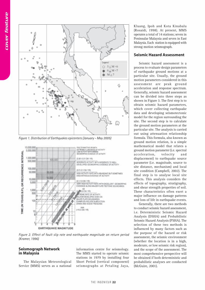
Indo-Australia plate is moving slowlynortheastward (7cm/year). This causespressure to build up and eventually apoint will be reached where thestrength of the rock cannot resist theimposed stresses, which are releasedin an earthquake as seismic waves.The Sumatra Subduction Zone tendsto have earthquakes measured atmagnitude 9. Besides that, PeninsularMalaysia is closer to the Sumatrafault. This clearly defined transformfault is laid in the interior of Sumatrathat is parallel to the trend of the plateboundary as a result of the componentof plate-motion. The Sumatra Faulttends to have earthquakes ofmagnitude 7.7. Figure 1 shows thedistribution of earthquakes withmagnitude above 5 for the period ofJanuary to May 2005.
Recent giant earthquake ofDecember 26, 2004 (magnitude 9.2),which was located over the off westcoast of Northern Sumatra, was wellpredicted (Rosaidi, 2001). Theprediction was based on the returnperiod of large earthquakes off thewest coast of Northern Sumatra inabout 70-100 years. The previouslarge earthquake off the west coastof Northern Sumatra was in 1935with a magnitude of 7.7. The futuresignificant earthquakes would beover the Sumatra Fault and mightgive considerable shaking to thewestern part of Peninsular Malaysia.The previous large earthquake overthe Sumatra fault was in 1892 withmagnitude 7.7. Based on the chartin Figure 2, it can be seen that thereturn period for earthquake withmagnitude above 7 and slip rateaveragely ± 15mm/year, is about100-150 years.
Earthquake Induced Energy:Sources And Hazard Analysis ForStructural Earthquake Resistant DesignIn Peninsular Malaysia c
over
featu
re
T H E I N G E N I E U R
Seismograph Networkin Malaysia
The Malaysian MeteorologicalService (MMS) serves as a national
information centre for seismology.The MMS started to operate seismicstations in 1979 by installing fourShort Period (vertical component)seismographs at Petaling Jaya,
22
Kluang, Ipoh and Kota Kinabalu(Rosaidi, 1998). At present, MMSoperates a total of 14 stations; seven inPeninsular Malaysia and seven in EastMalaysia. Each station is equipped withstrong motion seismograph.
Seismic Hazard Assessment
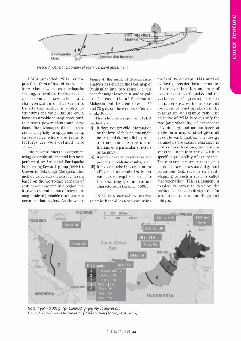
Seismic hazard assessment is aprocess to evaluate design parametersof earthquake ground motions at aparticular site. Usually, the groundmotion parameters considered in thisassessment are peak groundacceleration and response spectrum.Generally, seismic hazard assessmentcan be divided into three steps asshown in Figure 3. The first step is toobtain seismic hazard parameters,which cover collecting earthquakedata and developing seismotectonicmodel for the region surrounding thesite. The second step is to calculatethe ground motion parameters at theparticular site. The analysis is carriedout using attenuation relationshipformula. This formula, also known asground motion relation, is a simplemathematical model that relates aground motion parameter (i.e. spectralacceleration, velocity anddisplacement) to earthquake sourceparameter (i.e. magnitude, source tosite distance, mechanism) and localsite condition (Campbell, 2002). Thefinal step is to analyse local siteeffects. This analysis considers theeffects of topography, stratigraphy,and shear strength properties of soil.These characteristics often exert amajor influence on damage patternsand loss of life in earthquake events.
Generally, there are two methodsto conduct seismic hazard assessment,i.e. Deterministic Seismic HazardAnalysis (DSHA) and ProbabilisticSeismic Hazard Analysis (PSHA). Theselection of these two methods isinfluenced by many factors such asthe purpose of the hazard or riskassessment, the seismic environment(whether the location is in a high,moderate, or low seismic risk region),and the scope of the assessment. Themost comprehensive perspective willbe obtained if both deterministic andprobabilistic analyses are conducted(McGuire, 2001).
Figure 1. Distribution of Earthquakes epicenters (January - May 2005)
Figure 2. Effect of fault slip rate and earthquake magnitude on return period(Kramer, 1996)
cover
featu
re
T H E I N G E N I E U R 23
probability concept. This methodexplicitly consider the uncertaintiesof the size, location and rate ofoccurrence of earthquake, and thevariation of ground motioncharacteristics with the size andlocation of earthquakes in theevaluation of seismic risk. Theobjective of PSHA is to quantify therate (or probability) of exceedanceof various ground-motion levels ata site (or a map of sites) given allpossible earthquakes. The designparameters are usually expressed interms of accelerations, velocities orspectral accelerations with aspecified probability of exceedance.These parameters are mapped on anational scale for a standard groundconditions (e.g. rock or stiff soil).Mapping to such a scale is calledmacrozonation. This assessment isneeded in order to develop theearthquake resistant design code forstructures such as buildings andbridges.
DSHA preceded PSHA as theprevalent form of hazard assessmentfor maximum (worst case) earthquakeshaking. It involves development ofa seismic scenario andcharacterization of that scenario.Usually this method is applied tostructures for which failure couldhave catastrophic consequences, suchas nuclear power plants and largedams. The advantages of this methodare its simplicity to apply and beingconservative where the tectonicfeatures are well defined (linesources).
The seismic hazard assessmentusing deterministic method has beenperformed by Structural EarthquakeEngineering Research group (SEER) inUniversiti Teknologi Malaysia. Thismethod calculates the seismic hazardbased on the worst-case scenario ofearthquake expected in a region andit covers the estimation of maximummagnitude of probable earthquake tooccur in that region. As shown in
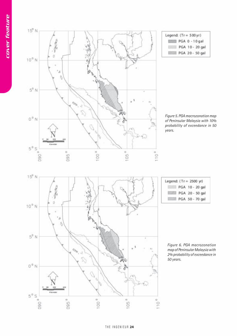
Figure 4, the result of deterministicanalysis has divided the PGA map ofPeninsular into two zones, i.e. thezone for range between 30 and 50 galson the east side of PeninsularMalaysia and the zone between 50and 70 gals on the west side (Adnan,et al., 2002).
The shortcomings of DSHAmethod are:(i) it does not provide information
on the level of shaking that mightbe expected during a finite periodof time (such as the usefullifetime of a particular structureor facility)
(ii) it produces very conservative andperhaps unrealistic results, and
(iii) it does not take into account theeffects of uncertainties in thevarious steps required to computethe resulting ground motioncharacteristics (Kramer, 1996).
PSHA is a method to analyseseismic hazard assessment using
Note: 1 gal = 0.001 g; 1g= 9.8m/s2 (g=gravity acceleration)Figure 4. Peak Ground Acceleration (PGA) contour (Adnan, et al., 2002).
Figure 3. General procedure of seismic hazard assessment
cover
featu
re
T H E I N G E N I E U R
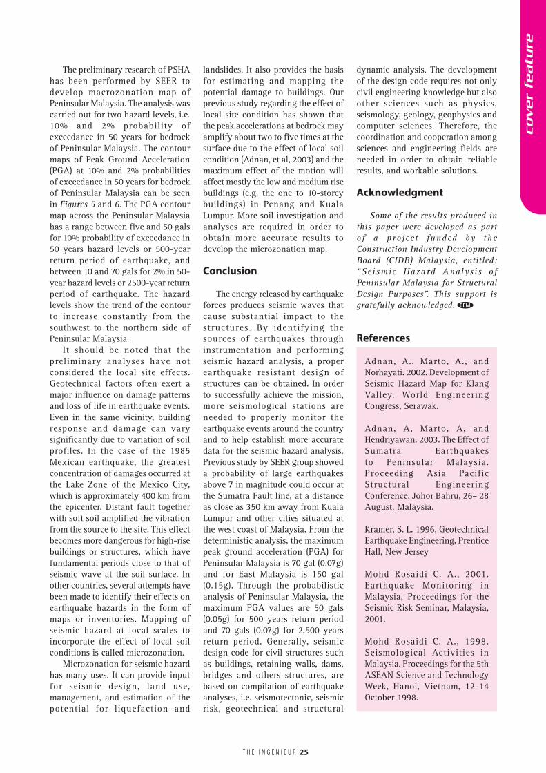
Figure 6. PGA macrozonationmap of Peninsular Malaysia with2% probability of exceedance in50 years.
Figure 5. PGA macrozonation mapof Peninsular Malaysia with 10%probability of exceedance in 50years.
24
cover
featu
re
T H E I N G E N I E U R
The preliminary research of PSHAhas been performed by SEER todevelop macrozonation map ofPeninsular Malaysia. The analysis wascarried out for two hazard levels, i.e.10% and 2% probability ofexceedance in 50 years for bedrockof Peninsular Malaysia. The contourmaps of Peak Ground Acceleration(PGA) at 10% and 2% probabilitiesof exceedance in 50 years for bedrockof Peninsular Malaysia can be seenin Figures 5 and 6. The PGA contourmap across the Peninsular Malaysiahas a range between five and 50 galsfor 10% probability of exceedance in50 years hazard levels or 500-yearreturn period of earthquake, andbetween 10 and 70 gals for 2% in 50-year hazard levels or 2500-year returnperiod of earthquake. The hazardlevels show the trend of the contourto increase constantly from thesouthwest to the northern side ofPeninsular Malaysia.
It should be noted that thepreliminary analyses have notconsidered the local site effects.Geotechnical factors often exert amajor influence on damage patternsand loss of life in earthquake events.Even in the same vicinity, buildingresponse and damage can varysignificantly due to variation of soilprofiles. In the case of the 1985Mexican earthquake, the greatestconcentration of damages occurred atthe Lake Zone of the Mexico City,which is approximately 400 km fromthe epicenter. Distant fault togetherwith soft soil amplified the vibrationfrom the source to the site. This effectbecomes more dangerous for high-risebuildings or structures, which havefundamental periods close to that ofseismic wave at the soil surface. Inother countries, several attempts havebeen made to identify their effects onearthquake hazards in the form ofmaps or inventories. Mapping ofseismic hazard at local scales toincorporate the effect of local soilconditions is called microzonation.
Microzonation for seismic hazardhas many uses. It can provide inputfor seismic design, land use,management, and estimation of thepotential for liquefaction and
landslides. It also provides the basisfor estimating and mapping thepotential damage to buildings. Ourprevious study regarding the effect oflocal site condition has shown thatthe peak accelerations at bedrock mayamplify about two to five times at thesurface due to the effect of local soilcondition (Adnan, et al, 2003) and themaximum effect of the motion willaffect mostly the low and medium risebuildings (e.g. the one to 10-storeybuildings) in Penang and KualaLumpur. More soil investigation andanalyses are required in order toobtain more accurate results todevelop the microzonation map.
Conclusion
The energy released by earthquakeforces produces seismic waves thatcause substantial impact to thestructures. By identifying thesources of earthquakes throughinstrumentation and performingseismic hazard analysis, a properearthquake resistant design ofstructures can be obtained. In orderto successfully achieve the mission,more seismological stations areneeded to properly monitor theearthquake events around the countryand to help establish more accuratedata for the seismic hazard analysis.Previous study by SEER group showeda probability of large earthquakesabove 7 in magnitude could occur atthe Sumatra Fault line, at a distanceas close as 350 km away from KualaLumpur and other cities situated atthe west coast of Malaysia. From thedeterministic analysis, the maximumpeak ground acceleration (PGA) forPeninsular Malaysia is 70 gal (0.07g)and for East Malaysia is 150 gal(0.15g). Through the probabilisticanalysis of Peninsular Malaysia, themaximum PGA values are 50 gals(0.05g) for 500 years return periodand 70 gals (0.07g) for 2,500 yearsreturn period. Generally, seismicdesign code for civil structures suchas buildings, retaining walls, dams,bridges and others structures, arebased on compilation of earthquakeanalyses, i.e. seismotectonic, seismicrisk, geotechnical and structural
dynamic analysis. The developmentof the design code requires not onlycivil engineering knowledge but alsoother sciences such as physics,seismology, geology, geophysics andcomputer sciences. Therefore, thecoordination and cooperation amongsciences and engineering fields areneeded in order to obtain reliableresults, and workable solutions.
Acknowledgment
Some of the results produced inthis paper were developed as partof a project funded by theConstruction Industry DevelopmentBoard (CIDB) Malaysia, entitled:“Seismic Hazard Analysis ofPeninsular Malaysia for StructuralDesign Purposes”. This support isgratefully acknowledged.
References
Adnan, A., Marto, A., andNorhayati. 2002. Development ofSeismic Hazard Map for KlangValley. World EngineeringCongress, Serawak.
Adnan, A, Marto, A, andHendriyawan. 2003. The Effect ofSumatra Earthquakesto Peninsular Malaysia.Proceeding Asia PacificStructural EngineeringConference. Johor Bahru, 26– 28August. Malaysia.
Kramer, S. L. 1996. GeotechnicalEarthquake Engineering, PrenticeHall, New Jersey
Mohd Rosaidi C. A., 2001.Earthquake Monitoring inMalaysia, Proceedings for theSeismic Risk Seminar, Malaysia,2001.
Mohd Rosaidi C. A., 1998.Seismological Activities inMalaysia. Proceedings for the 5thASEAN Science and TechnologyWeek, Hanoi, Vietnam, 12-14October 1998.
25
BEM
cover
featu
re
T H E I N G E N I E U R
By Iszuan Shah Syed Ismail, Azmi Omar, Hamdan Hassan , * TNB Research Sdn. Bhd.
TNB has been involved with solarpower since the 1980s. At thattime, most solar projects
undertaken by TNB in PeninsularMalaysia were associated withdecentralized stand-alone system forthe Rural Electrification Programme.As it is very expensive to provideelectricity supply from the grid to therural area, stand-alone solar PVsystems were recognized as a cost-effective option to electrify the remotevillages.
Building solar power stations willcontribute to the objectives of theEighth Malaysian Plan to supplyabout 5% of electrical energy throughthe application of renewable sourcesof energy.
In cases where communities arewidely scattered, remote and far awayfrom the unified grid, solar energy can
play an important role in their socio-economic development. Solarphotovoltaic is the most promisingtechnology to supply energy to thosecommunities. Remote communitiesand villagers are characterized, inmost cases, by being very small insize, widely spread with relatively lowload demands. Their main domesticenergy consumption needs are forresidential purposes (e.g. smalllighting units, radio, television,refrigerator, etc). Each communityconsists of between 30 and 50 houses.
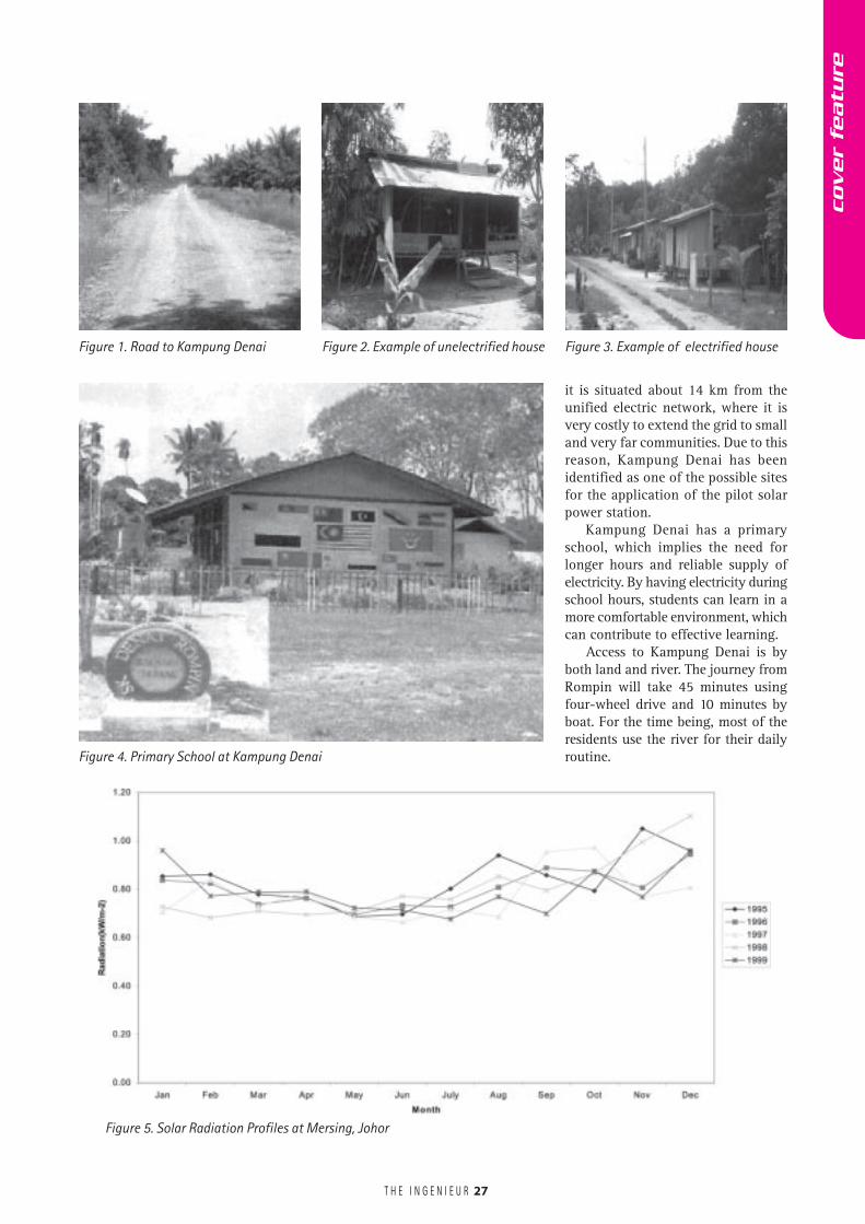
Kampung Denai is located about35 km from the nearest main roadconnecting Rompin and Mersing. Theresidents are 158 orang asli scattered
26
in 22 houses. The current electricitysupply is from an 18.6 kW poweredgenerator set. The electricity supplyis from 7 p.m. to 11 p.m. which isinsufficient for the residents.
With this pilot project, TNBResearch hopes to design and installa standardized, stand-alone SolarPower Station suitable for thiscountry. The technical capabilities andeconomic value of the pilot projectcan be demonstrated.
CRITERIA OF SELECTION
Kampung Denai has been chosento be the first pilot solar power stationfor its remote location. Furthermore,
Pilot Centralized Solar Power StationIn Remote Village, Rompin, Pahang
Malaysia has electrified the whole Peninsular Malaysia with about 95% grid connected electricity.The other 5% is associated with a number of widely deployed unelectrified small rural areas which arerelated with the aborigines. Diesel-electric power supply to the rural area, Kg. Denai has been replacedby a PV-diesel-battery hybrid system.
The use of photovoltaic modules as a hybrid component in these systems is marginally cost-effective.In still smaller systems such as those found at remote holiday homes, PV modules are more costeffective rather than extending the grid.
The usual or normal system using solar as a source for electricity in rural areas is a standalone systemfor each house. For this project, a pilot centralized solar power station was the source of electricity tolight up the 15 houses at Kampung Denai, Rompin, Pahang, Malaysia. This system was the first solarphotovoltaic system installed at an aborigine’s village in Malaysia. The village was chosen becausethere is a primary school. Moreover, the remote communities are living in stratification, which makeselectrical wiring easier.
The pilot solar hybrid power station consisted of 10 kW photovoltaic panels, 10 kW inverter, 150 kWhbatteries and other balance systems. A generator set with capacity of 12.5kVA was installed formonsoon season.
This paper will present the status of the system, system load and future developments.
* The authors are attached to TNB Research Sdn Bhd (TNBR), a wholly owned subsidiary of TenagaNasional Berhad (TNB). The views expressed herein are attributable to the authors and do notrepresent those of TNB and TNBR.
cover
featu
re
T H E I N G E N I E U R 27
it is situated about 14 km from theunified electric network, where it isvery costly to extend the grid to smalland very far communities. Due to thisreason, Kampung Denai has beenidentified as one of the possible sitesfor the application of the pilot solarpower station.
Kampung Denai has a primaryschool, which implies the need forlonger hours and reliable supply ofelectricity. By having electricity duringschool hours, students can learn in amore comfortable environment, whichcan contribute to effective learning.
Access to Kampung Denai is byboth land and river. The journey fromRompin will take 45 minutes usingfour-wheel drive and 10 minutes byboat. For the time being, most of theresidents use the river for their dailyroutine.
Figure 5. Solar Radiation Profiles at Mersing, Johor
Figure 1. Road to Kampung Denai Figure 2. Example of unelectrified house Figure 3. Example of electrified house
Figure 4. Primary School at Kampung Denai
cover
featu
re
T H E I N G E N I E U R 28
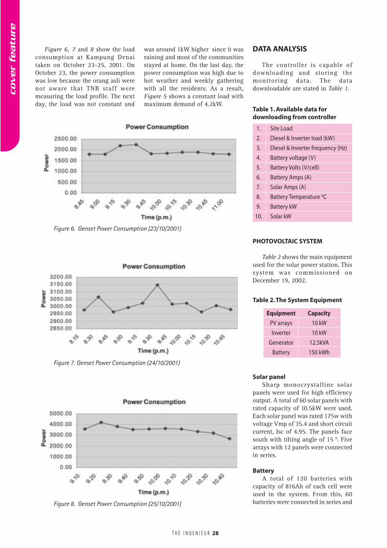
Figure 6, 7 and 8 show the loadconsumption at Kampung Denaitaken on October 23-25, 2001. OnOctober 23, the power consumptionwas low because the orang asli werenot aware that TNB staff weremeasuring the load profile. The nextday, the load was not constant and
DATA ANALYSIS
The controller is capable ofdownloading and storing themonitoring data. The datadownloadable are stated in Table 1.
was around 1kW higher since it wasraining and most of the communitiesstayed at home. On the last day, thepower consumption was high due tohot weather and weekly gatheringwith all the residents. As a result,Figure 5 shows a constant load withmaximum demand of 4.2kW.
Table 1. Available data fordownloading from controller
Table 2. The System Equipment
Solar panelSharp monocrystalline solar
panels were used for high efficiencyoutput. A total of 60 solar panels withrated capacity of 10.5kW were used.Each solar panel was rated 175w withvoltage Vmp of 35.4 and short circuitcurrent, Isc of 4.95. The panels facesouth with tilting angle of 15 0. Fivearrays with 12 panels were connectedin series.
BatteryA total of 120 batteries with
capacity of 816Ah of each cell wereused in the system. From this, 60batteries were connected in series and
Figure 6. Genset Power Consumption (23/10/2001)
Figure 7. Genset Power Consumption (24/10/2001)
Figure 8. Genset Power Consumption (25/10/2001)
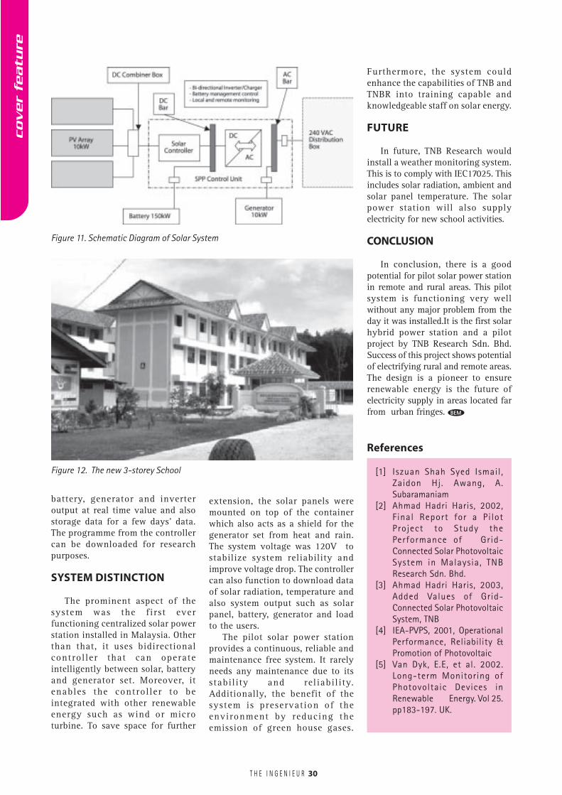
PHOTOVOLTAIC SYSTEM
Table 2 shows the main equipmentused for the solar power station. Thissystem was commissioned onDecember 19, 2002.
cover
featu
re
Equipment Capacity
PV arrays 10 kW
Inverter 10 kW
Generator 12.5kVA
Battery 150 kWh
1. Site Load
2. Diesel & Inverter load (kW)
3. Diesel & Inverter frequency (Hz)
4. Battery voltage (V)
5. Battery Volts (V/cell)
6. Battery Amps (A)
7. Solar Amps (A)
8. Battery Temperature oC
9. Battery kW
10. Solar kW
T H E I N G E N I E U R
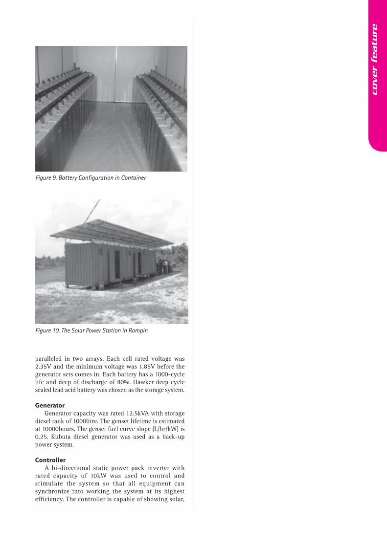
Figure 9. Battery Configuration in Container
Figure 10. The Solar Power Station in Rompin
paralleled in two arrays. Each cell rated voltage was2.35V and the minimum voltage was 1.85V before thegenerator sets comes in. Each battery has a 1000-cyclelife and deep of discharge of 80%. Hawker deep cyclesealed lead acid battery was chosen as the storage system.
GeneratorGenerator capacity was rated 12.5kVA with storage
diesel tank of 1000litre. The genset lifetime is estimatedat 10000hours. The genset fuel curve slope (L/hr/kW) is0.25. Kubuta diesel generator was used as a back-uppower system.
ControllerA bi-directional static power pack inverter with
rated capacity of 10kW was used to control andstimulate the system so that all equipment cansynchronize into working the system at its highestefficiency. The controller is capable of showing solar,
cover
featu
re
T H E I N G E N I E U R 30
BEM
Figure 12. The new 3-storey School
Figure 11. Schematic Diagram of Solar System
References
[1] Iszuan Shah Syed Ismail,Zaidon Hj. Awang, A.Subaramaniam
[2] Ahmad Hadri Haris, 2002,Final Report for a Pi lotProject to Study thePerformance of Grid-Connected Solar PhotovoltaicSystem in Malaysia, TNBResearch Sdn. Bhd.
[3] Ahmad Hadri Haris, 2003,Added Values of Grid-Connected Solar PhotovoltaicSystem, TNB
[4] IEA-PVPS, 2001, OperationalPerformance, Reliability &Promotion of Photovoltaic
[5] Van Dyk, E.E, et al. 2002.Long-term Monitoring ofPhotovoltaic Devices inRenewable Energy. Vol 25.pp183-197. UK.
battery, generator and inverteroutput at real time value and alsostorage data for a few days’ data.The programme from the controllercan be downloaded for researchpurposes.
SYSTEM DISTINCTION
The prominent aspect of thesystem was the first everfunctioning centralized solar powerstation installed in Malaysia. Otherthan that, it uses bidirectionalcontroller that can operateintelligently between solar, batteryand generator set. Moreover, itenables the controller to beintegrated with other renewableenergy such as wind or microturbine. To save space for further
extension, the solar panels weremounted on top of the containerwhich also acts as a shield for thegenerator set from heat and rain.The system voltage was 120V tostabilize system reliability andimprove voltage drop. The controllercan also function to download dataof solar radiation, temperature andalso system output such as solarpanel, battery, generator and loadto the users.
The pilot solar power stationprovides a continuous, reliable andmaintenance free system. It rarelyneeds any maintenance due to itsstabil i ty and rel iabil i ty.Additionally, the benefit of thesystem is preservation of theenvironment by reducing theemission of green house gases.
Furthermore, the system couldenhance the capabilities of TNB andTNBR into training capable andknowledgeable staff on solar energy.
FUTURE
In future, TNB Research wouldinstall a weather monitoring system.This is to comply with IEC17025. Thisincludes solar radiation, ambient andsolar panel temperature. The solarpower station will also supplyelectricity for new school activities.
CONCLUSION
In conclusion, there is a goodpotential for pilot solar power stationin remote and rural areas. This pilotsystem is functioning very wellwithout any major problem from theday it was installed.It is the first solarhybrid power station and a pilotproject by TNB Research Sdn. Bhd.Success of this project shows potentialof electrifying rural and remote areas.The design is a pioneer to ensurerenewable energy is the future ofelectricity supply in areas located farfrom urban fringes.
cover
featu
re

T H E I N G E N I E U R 31
Code Of Professional Conduct1.0 A Registered Engineer shall at all times hold
paramount the safety, health and welfare of thepublic.
1.1 A Professional Engineer shall approve and sign onlythose engineering documents that he has preparedor are prepared under his direct supervision.
1.2 A Professional Engineer shall certify satisfactorycompletion of a piece of work only if he has controlover the supervision of the construction or installationof that work, and only if he is satisfied that theconstruction or installation has fulfilled therequirements of the engineering design andspecifications.
1.3 A Registered Engineer shall not reveal facts, data orinformation without the prior consent of the clientor employer except as authorized or required by lawor when withholding of such information is contraryto the safety of the public.
1.4 A Registered Engineer having knowledge of anyviolation of this code and Local Authorities regulationsshall report thereon to appropriate professional bodiesand, when relevant, also to public authorities andcooperate with the proper authorities in furnishingsuch information or assistance as may be required.
1.5 When the professional advice of a ProfessionalEngineer is overruled and amended contrary to hisadvice, the Professional Engineer shall, if theamendment may in his opinion give rise to situationthat may endanger life and/or property, notify hisemployer or client and such other authority as maybe appropriate and explain the consequences to beexpected as a result of his advice being overruled andamended.
2.0 A Registered Engineer shall undertake assignmentsonly if he is qualified by education and experiencein the specific technical fields in which he isinvolved.
2.1 A Professional Engineer shall not affix his signatureto any plan or document dealing with subject matterin which he lacks competence, nor to any plan ordocument not prepared under his direction andcontrol.
2.2 A Professional Engineer shall not accept assignmentand assume responsibility for coordination of an entire
project and sign and stamp (P.E. stamp) theengineering documents for the entire project unlesseach technical segment of the project is signed andstamped personally by the qualified engineer who hasprepared the respective segment of the project.
3.0 A Registered Engineer shall issue public statementsonly in an objective and truthful manner.
3.1 A Registered Engineer shall be objective and truthfulin professional reports, statements and testimony. Heshall include all relevant and pertinent informationin such reports, statements, or testimony, whichshould bear the date indicating when it was current.
3.2 A Registered Engineer may express publicly onlytechnical opinions that are founded upon hiscompetence and knowledge of the facts in the subjectmatter.
3.3 A Registered Engineer shall not issue statement,criticism or argument on technical matter that isinspired or paid for by interested parties, unless hehas prefaced his comments by explicitly identifyingthe interested parties on whose behalf he is speakingand by revealing the existence of any interest he mayhave in the matter.
4.0 A Registered Engineer shall act for each employeror clients as faithful agent or trustee.
4.1 A Registered Engineer shall disclose all known orpotential conflicts of interest that could influenceor appear to influence his judgement or the qualityof his services.
4.2 A Registered Engineer shall not acceptcompensation, financial or otherwise, from morethan one party for services on the same project, orfor services pertaining to the same project, unlessthe circumstances are fully disclosed and agreed toby all interested parties.
4.3 A Registered Engineer shall not solicit or acceptfinancial or other valuable consideration, directly orindirectly, from outside agents in connection withthe work for which he is responsible.
4.4 A Registered Engineer as advisor or director of acompany or an agency shall not participate indecision with respect to particular services solicitedor provided by him or his organization.
CIRCULAR NO. 3/2005
guid
elines
✃

T H E I N G E N I E U R 32
4.5 A Registered Engineer shall not solicit or accept acontract from a body or agency on which a principalor officer of his organization served as a member ofthat body or agency unless with knowledge andconsent of that body or agency.
4.6 A Registered Engineer while acting in his professionalcapacity shall disclose in writing to his client of thefact if he is a director or member of or substantialshare holder in or agent for any contracting ormanufacturing company or firm or business or hasany financial interest in any such company or firmor business, with which he deals on behalf of hisclient.
4.7 All professional advice shall be given in good faith.
5.0 A Registered Engineer shall conduct himselfhonourably, responsibly, ethically and lawfully soas to enhance the honour, reputation andusefulness of the profession.
5.1 A Registered Engineer shall not falsify hisqualifications or permit misrepresentation of his orhis associates’ qualifications. He shall notmisrepresent or exaggerate his responsibility in orfor the subject matter of prior assignments.Brochures or other presentations incident to thesolicitation of employment shall not misrepresentpertinent facts concerning employers, employees,associates, joint venturers, or past accomplishments.
5.2 A Registered Engineer shall not offer, give, solicit orreceive, either directly or indirectly, any contributionto influence the award of a contract which may bereasonably construed as having the effect of intentto influencing the award of a contract. He shall notoffer any gift or other valuable consideration in orderto secure work. He shall not pay a commission,percentage or brokerage fee in order to secure work.
5.3 A Registered Engineer shall check with due diligencethe accuracy of facts and data before he signs orendorses any statement or claim. He shall not signon such documents unless, where necessary,qualifications on errors and inaccuracies have beenmade.
5.4 A Registered Engineer shall respond, withinreasonable time, to communication from the Boardor any other relevant authority on matter pertainingto his professional service.
5.5 A Registered Engineer shall not maliciously injureor attempt to maliciously injure whether directly orindirectly the professional reputation, prospect orbusiness of another Engineer.
5.6 A Registered Engineer shall not directly or indirectly
(1) supplant or attempt to supplant anotherEngineer;
(2) intervene or attempt to intervene in or inconnection with engineering work of any kindwhich to his knowledge has already beenentrusted to another Engineer; or
(3) take over any work of another Engineer actingfor the same client unless he has(i) obtained a letter of release from the other
Engineer or obtain such letter through theclient, provided that this requirement maybe waived by the Board; or
(ii) been formally notified by the client that theservices of that other Engineer have beenterminated in accordance with theprovisions of any contract entered intobetween that Engineer and the client;provided always that, in case of dispute overnon-payment or quantum of anyoutstanding fees, the client shall requestthe Board to be the stakeholder under theprovision of Section 4(1)(e)(ea)
5.7 Except with the prior approval of the Board, aRegistered Engineer shall not be a director orexecutive of or substantial shareholder in or agentfor any contracting or manufacturing company orfirm or business related to building or engineering.If such approval is given, such Engineer shall notundertake any contract work wherein he is engagedas a consulting engineer in such project unless it isin respect of a “design and build” project.
5.8 A Registered Engineer shall not be a medium ofpayment made on his client’s behalf unless he is sorequested by his client nor shall he, in connectionwith work on which he is employed, place contractsor orders except with the authority of and on behalfof his client.
5.9 A Registered Engineer shall not
(1) offer to make by way of commission or any otherpayment for the introduction of his professionalemployment; or
(2) except as permitted by the Board, advertise inany manner or form in connection with hisprofession.
5.10 A Professional Engineer in private practice shall notwithout the approval of the Board enter intoprofessional partnership with any person other thana Professional Engineer in private practice, aRegistered Architect, a Registered Quantity Surveyoror a licensed Land Surveyor.
guid
elines
✃

Update
T H E I N G E N I E U R
Policy OnThe Use Of WaterRelated Products
Policy on uPVc pipes and fittings
� SYABAS will continue to use uPVc pipes and fittings
(Class E) but restricted to external reticulation for
low cost residential development projects until
December 31, 2005. Beyond this date, the use of any
uPVc pipes for any external reticulation will not be
approved.
� SYABAS will not approve the use of uPVc pipes and
fittings for internal plumbing as a continuation of
current policy.
Policy on the use of FRP Panel tanks
� SYABAS will not approve the use of FRP Panel as a
ground tank and elevated tank for system to be
handed over to SYABAS as a continuation of current
policy.
� SYABAS will not approve the use of FRP Panel as
suction tank and roof tank for buildings (internal
system) as a continuation of current policy.
� Based on the practical issues of replacing or
modification to existing supporting structures,
SYABAS may continue to use FRP Panel as a
replacement/maintenance of some existing FRP Panel
tanks in Selangor, WP Kuala Lumpur and Putrajaya.
Issued by Syarikat Bekalan Air Selangor Sdn Bhd(SYABAS)
as at April 8, 2005
T H E I N G E N I E U R
Water Resources Management InMalaysia – The Way ForwardBy Ir. Harbans Singh K.S.1
Instructions And Variations*
34
The topic of this paper appears at first blush to dealwith two important but disparate topics. However,on a closer examination, there is a significant nexus
between the two if one were to examine them in the lightof the administration of a typical contract and eventuallyin situations involving claims 2. To do justice to the abovecaptioned title, it is my intention to deal with eachseparately and then attempt to establish their relationshipwithin the context of a construction contract; a task to beaccomplished within the time constraints imposed on thissession.
In dealing with the individual topics, the discussion willbe confined only to the principal matters and issues; thedetails being left to be referred to the relevant treatises.Furthermore, the presentation on Instructions will delveprimarily on the subject of ‘Instructions to Contractors’and Variations focused on ‘Variation Claims’. In theprocess, the main areas of concern for practitioners willbe touched upon and the principal issues of contention ineveryday practice amplified. I am sure that the otherlearned presenters will expand upon some of the collateralissues directly or indirectly in their respective papers soas to present the whole picture to the participants; thisbeing the main objective of this conference.
INSTRUCTIONS TO THE CONTRACTOR 3
In administering a particular contract, one of the mostimportant powers available to the contract administratoris the issuance of instructions. Whether these be intendedto ensure that the contractor rectifies defective work orcarries out variations to the contract, the power to issuesuch instruction remains the most effective tool in thehands of the contract administrator.
In parallel to the existence of such power, is acorresponding duty to issue relevant instructionspertaining to specific matters either on his own volitionor upon the request of the contractor; such instructionsbeing necessary to enable the purposes of the contract tobe met. This duty is amply underlined in RIBA’s Plan ofWork Diagrams 9 to 11 4 to which reference be made. It isthe intent of this section to develop the initial introductionand explain certain salient features in sufficient detail.
Contractual Provisions
In the absence of any express contractual provision tothe contrary, there is no general right under a typicalengineering/construction contract for the contract
administrator and/or the employer to issue instructionsto the contractor 5.
In practice, however, most standard forms of conditionsof contract include such express contract provisions;examples of which include PAM ‘98 Forms (With &Without Quantities Edns) Clause 2.0, CIDB Form (2000Edn) Clause 3, IEM.CE1/89 Form Clause 5, JKR 203 &203A Forms Clause 5, etc.
It is pertinent to note that except for the PAM ‘98 Sub-Contract Form, there are no such express provisions inthe other commonly encountered Nominated Sub-ContractForms such as JKR 203N (Rev. 10/83), JKR 203P (1983),IEM.CES 1/90; 6 etc.
* This paper was presented at KLRCA/MIArb’s InternationalConference on Construction Law and Arbitration held on the 26rd
- 28th April 2005 at Nikko Hotel, Kuala Lumpur.1. Director, HSH Consult Sdn. Bhd.2. Especially those going under the title of ‘Variation Claims’.3. See Ir. Harbans Singh K.S. ‘Engineering and Construction Contracts
Management: Commencement and Administration’ at P253 –260.
4. Covering Stages J to L in conjunction with the NJCC Guide ‘TheManagement of Building Contracts’.
5. See ‘Construction Contracts Law and Management’ [2nd Edn] byMurdoch and Hughes at P262.
6. For use in conjunction with IEM.CE1/89 Form (For Civil EngineeringWorks).
Part 1
engin
eeri
ng &
law

T H E I N G E N I E U R
Form
An instruction can be either of an oral nature or in writing;though the latter appears to the more common form. Amajority of the standard forms of conditions of contractrequire all instructions issued by the contract administratorto be ‘in writing’; an example being clause 2.5 7 PAM ‘98(With Quantities) Edition which stipulates:
All instructions issued by the Architect shall be in writing.If the Architect issues an instruction otherwise than inwriting it shall have no immediate effect, but shall beconfirmed in writing by the contractor to the Architectwithin seven (7) days. If within seven (7) days uponreceipt of the contractor’s confirmation, the Architect doesnot dissent to it in writing, then the contractor’sconfirmation shall be deemed to be an Architect’sInstruction. The said instruction shall have taken effecton the date when the contractor’s confirmation was issued.
Similar requirements are expressed in the various otherforms.
Cognisance should be taken of the following issuespertaining to this matter 8:
� In the clauses adverted to here above, the principalrequirement is for the instruction to be merely inwriting. Therefore, the instruction need not be in anyform so long as it is written. This would presumablyencompass letters, memoranda, facsimile, drawings,confirmed minutes of meeting and entries in site diaries.
It is a moot point whether ‘e-mail’ falls within thisclassification.
� The general position is that the contractor is not obligedto carry out an instruction until it is reduced to writingby the contract administrator. The date of such aninstruction shall be the date it is subsequentlyconfirmed in writing;
� If the contractor receives oral instructions, thecontractor must write in to the contract administratorconfirming the oral instructions. The latter then has areasonable period 9 to effect such written confirmation.The instruction is then valid from the date ofconfirmation; and
� If the contract administrator dissents or refuses toconfirm, the contractor need not act on the instruction.If, however, the contractor nevertheless complies withthe oral instruction; the contract administrator mayconfirm the instruction at any time up to the issue ofthe final certificate i.e. retrospective confirmation.
Types
As most standard clauses pertaining to instructions arewidely drafted, the range of such instructions that can beissued by a contract administrator are accordingly
immense. However, in practice the more commonlyencountered instructions are of the principal varieties asstipulated herebelow 10:
� To vary works under the contract;
� To resolve any discrepancy 11 in or between the contractdocuments;
� To remove from site any materials or goods broughtthereon by the contractor and the substitution of anyother materials or goods therefore;
� To remove and/or re-execute any works executed;
� To open up for inspection of any work covered up;
� To rectify and/or make good any defects;
� To dismiss from the works any person under thecontract as empowered by the specific clauses;
� To expend any Provisional Sum/P.C. Sum included inthe Contract Sum;
� To undertake any matter which is necessary andincidental to the carrying out and completion of theworks under the contract; and
� To carry out specific requirements of the contract forwhich the contract administrator is empowered underthe contract.
Procedural Requirements and Validity
The procedural requirements governing the subject of‘instructions’ are usually stipulated in the respectiveconditions of contract. To be effective the instructionmust strictly comply with the form and procedure as laiddown in the conditions of contract.
A number of issues arising from this matter which mustbe taken due note of are listed hereunder:
� Once a contractor has received a properly issuedinstruction from the contract administrator, the dutyof compliance is on him e.g. Clause 2.1 PAM ‘98 Forms(With & Without Quantities) Edns. 12 which reads:
7. Entitled ‘Instructions To Be In Writing’8. See also ‘The Malaysian Standard Form of Building Contract’ [2nd
Edn] by Sundra Rajoo.9. Usually about 7 days depending on the circumstances.10. See for example Clause 5(a) JKR 203 Form (Rev. 10/83) and Clause
10.01 Putrajaya Conditions of Main Contract.11. Ambiguity, inconsistency, divergence, etc.12. See also Clause 3.1 CIDB Form, Clause 5(b) JKR 203 & 203A
Forms, etc.
35
engin
eeri
ng &
law
T H E I N G E N I E U R
‘The contractor shall (subject to clauses 2.3 and 2.5)forthwith comply with all instructions issued to himby the Architect in writing in regard to any matter inrespect of which the Architect is expressly empoweredby these conditions to issue instructions’
The period for compliance should be within the durationexpressly stipulated in the instruction itself or if none isstated expressly, within a reasonable period thereof:London Borough of Hillingdon v Cutler 13.
� Should the contractor fail to comply, the remediesavailable to the employer are confined to the expresscontractual remedies and/or the remedies under thecommon law.
The express contractual remedies alluded to here aboveinclude:
(a) Employment of third parties to effect the work underthe instruction e.g. clause 2.2 PAM ‘98 Forms (With& Without Quantities) Edns, etc.; or
(b) Determination of the contractor’s employment if suchground is stipulated and the requirements met e.g.Clause 25.1 14 PAM ‘98 Forms With & WithoutQuantities) Edns, etc.
As for the common law remedies, this includes the extremeaction for breach of contract.
A contract administrator must be mindful not to issue aninvalid instruction; such an instruction being one wherethe contract administrator has:
(a) Acted ‘ultra-vires’ i.e. beyond the powers given tohim under either the contract and/or the letter ofdelegation of powers; or
(b) Not followed or breached the specific proceduralrequirements expressly stipulated in the contract.
A contractor if issued with such an instruction canchallenge its validity 15 and refuse to carry it out. Anyinsistence by the contract administrator or employer forthe contractor to effect such an instruction can be anactionable breach of contract. Should however thecontractor decide to comply with and carry out an invalidinstruction, he cannot subsequently look to the employerfor payment and/or compensation.
Two further issues that need to be considered in summingup this section concern the mode and the timing of theissue of instructions. The instructions are normally issuedat the behest of the employer 16, the contractadministrator’s initiative or upon application by thecontractor depending upon the particular circumstancesinvolved. The instructions usually can be issuedthroughout the duration of the contract i.e. right up tothe issue of the final certificate until the contractadministrator becomes ‘functusofficio’.
Liabilities
In issuing instructions to the contractor, the contractadministrator acts as an agent of the employer with realand/or ostensible (apparent) authority. Hence, theemployer is generally liable directly as principal, andvicariously for any breach of warranty on the part of hisagent: EMS Bowe (M) Sdn. Bhd. v KFC Holdings (M)Bhd. & Anor 17. However, this is subject to the importantcaveat as lucidly illustrated by Murdoch and Hughes inthe following extract 18:
….. a contract administrator who exceeds his or herauthority risks being held personally liable to a thirdparty with whom he or she deals. In addition, the law ofagency contains another trap for the unwary. This isthat any agent who signs a written contract on behalf ofa client will be treated as a party to it and thus personallyliable, unless the contract itself makes it clear that it issigned merely as an ‘agent’ …..
Pursuant to the above discussion, it is clear that wherethe contract administrator is expressly authorized 19toissue certain instructions the employer is bound. Butwhere he exceeds his authority he may be personallyliable for damages: Sika Contracts Ltd. v Gill 20.
INSTRUCTIONS AND VARIATIONS: THE NEXUS 21
For a variation to be tenable at law, it must be valid inthe first place. Unless such a change meets the validitytest, the contractual consequences ensuing thereof cannotarise and accordingly cannot be enforced. Therefore,the contractor cannot be compelled to comply with anyvariation order issued and he on his part may not beable to recover his contractual entitlements as toadditional costs and/or time, for instance. It is henceapparent that the central issue of validity forms theessence of a contractually tenable and thereforeenforceable variation; a matter that continues to generatedisputes in many a contract in the engineering/construction industry.
13. [1960] 2 All E.R. 361.14. e.g. sub-clause 25.1(iii) and (vi) for instance.15. See also clause 2.4 PAM ‘98 Forms.16. e.g. for matters involving changes in the employer’s requirements17. [1999] 6 CLJ 513. See also ‘Construction Law in Singapore and
Malaysia’ [2nd Edn] by Robinson & Lavers at P323.18. ‘Construction Contracts Law and Management’ [2nd Edn] at P258
& 259.19. either in the Conditions of Contract and/or Letter of Delegation
of Power.20. [1978] 9 BLR 15.21. See Ir. Harbans Singh K.S. ‘Engineering and Construction Contracts
Management: Post-Commencement Practice’ at P455 – 464.
36
engin
eeri
ng &
law
T H E I N G E N I E U R
The subsequent write-up has been formulated to addressthe instant areas of concern 22. As the boundaries of thelegal principles in this area of the variation field are stillnot clear, a general approach will be taken and wherenecessary references to pertinent judicial decisions ofthe non-conventional jurisdictions may be made to shedsome light on the possible ways of resolving theseproblem areas.
Valid Variations
(A) General
When one classifies a variation as ‘valid’, thefundamental reference is in terms of posing the question:has the change been carried out in compliance with avalid variation order? The latter therefore serves as theultimate ingredient in the context of the instantdiscussion.
The term variation order in turn has no magical meaningbut its precise ambit must be appreciated to ensure thatthe elements of validity are not compromised. The bestdefinition that can be of assistance is the one profferedby Prof. Vincent Powell-Smith in relation to engineeringcontracts which holds a ‘variation order’ to be 23:
An instruction of the engineer 24 to effect a change to theworks as defined in the contract documents. It iscommonplace for a variation simply to be issued as anengineer’s instruction; it being evident from the contentthat it is a variation. Alternatively, variations are issuedseparately on variation orders.
From the above definition, the principal elements of avalid variation order are:
� It must be in the form of an ‘instruction’ in the formal/contractual sense;
� The person issuing the instruction must be the contractadministrator or the person empowered under thecontract to issue such instruction;
� The instruction must effect a change to the works;and
� The works being changed or varied must be spelt outor defined in the contract documents.
Coupled to the abovementioned elements are a numberof relevant factors that must be considered in determiningthe validity of a variation order; the latter beingconsidered in detail in the subsequent write-up.
(B) Factors Determining Validity of Variation Order
Chow Kok Fong in ‘Law and Practice of ConstructionContract Claims’ 25 identifies two main factorsdetermining the validity of a valid variation order,namely:
� The legal nature of the proposed change i.e. contractconditions governing variations and the commonlaw rules governing the scope of change; and
� The formalities governing the change e.g. issue ofthe variation order by the designated person and theapplicable procedural requirements.
Each one of the said factors will be dealt with in a greaterdepth below.
1. Contract Conditions Governing Variations
It is settled law that a contractually valid variation ordercan only be issued if there is a term 26 in the contractpermitting the same and strictly in accordance with thisterm. Should there be no such term or that the provisionsof an existing term be not complied with, any variationorder thereupon issued may, for all intents and purposes,be contractually invalid and thereforeunenforceableTocater for the eventuality of permitting such variations tobe effected, most if not, all the standard forms of conditionsof contract have incorporated express stipulations in theconditions of contract thereto. Notable examples of theseinclude clause 28 CIDB Form, clause 24 JKR Forms 203 &203A, clause 23 IEM.CE 1/89 Form, etc.; which terms arealso reflected in ‘bespoke’ forms.
In the rare situation of the absence of such an expressstipulation in the contract or it being rendered invalid/unenforceable, following the discussion hereabove, theparties have only a number of alternatives available tothem; one of these being to enter into a supplementaryagreement to enable the varied work as envisaged to becarried out. To preclude such a situation from arisingand to obviate its attendant complications, it is necessaryfor the parties to ensure that not only the relevant expressprovisions are included in their contract from the veryoutset but these are religiously adhered to in theimplementation stage.
2. Common Law Rules Governing Variations
Notwithstanding the presence of and the satisfaction ofthe express contractual provisions governing the subjectof variation orders, the parties to a typical contract inimplementing such changes must be mindful of andcomply with the applicable common law rules whichencompass invalid omissions, ‘cardinal’ changes andrecovery without written variation orders.
The said areas of concern have to be dealt with especiallywhen one deals with the so called ‘Extra Contractual’claims.
22. Especially the contractor’s Variation Claims.23. See ‘An Engineering Contract Dictionary’ at P 563.24. i.e. the contract administrator.25. [2nd Edn] at P 50.26. or clause
37
engin
eeri
ng &
law
T H E I N G E N I E U R
T H E I N G E N I E U R
3. Issue by Designated Person
For a variation order to be upheld as contractually valid,one of the main requirements is that it must be issued bythe person empowered under the contract to effect thesame. Such a body or person might be the employerhimself, or the contract administrator, or any other bodyor person designated in the contract or authorizedexpressly under the contract.
The body or person so designated can be either named inthe contract or empowered through a formal letter ofdelegation of power issued after award of the contractduring the currency of the contract 27. The aboverequirement is neatly summed up in the following wordsby Robinson & Lavers 28:
‘The employer, under all standard forms, is required toexercise his right to change the contractor’s obligations,through the agency of the architect (or engineer orsupervision officer). The contractor is generally under noobligation to accept instructions direct from the employerexcept under some governmental forms where such a rightof direct communication is retained for reasons of nationalsecurity. The use of the architect as agent in this contextis necessary of course to ensure coordination of the design,to ensure standardized administrative procedures andbecause, in most cases, the initiator of the changes is thearchitect himself as his detailed design work progresses….
As can be distilled from the above extract, in mostcontracts, this power is delegated to the contractadministrator i.e. the Architect in the PAM Forms,Engineer in the IEM Forms, Employer’s Representativesin the Putrajaya Forms, etc. It is pertinent to note thatonce the contract designates a specific person as theofficial who is empowered to vary the works or a specificperson is delegated this duty, a variation order issued byany other person will not be contractually valid 29.Furthermore, in exercising this power, the contractadministrator must ensure that the said power meets thefollowing criteria 30:
� It covers the nature of the variation or change ordered;
� It covers the extent of the variation or changeenvisaged; and
� It meets any express time limit prescribed for exercisingsuch powers e.g. whether the contract permits variationorders to be issued after practical completion of work,etc.
Cognisance should also be taken of the followingcharacteristics and/or features of the power of the contractadministrator to vary works:
� The employer may (either in the contract or the letterof delegation of powers) subject the exercise of thesaid power to certain procedural and/or financiallimitations e.g. in Public Works Contracts, the prior
consent of the employer may be a pre-requisite tothe contract administrator’s issuing any variationorders; 31
� Where the contract administrator is empowered underthe contract to vary the works, his use of such poweras the employer’s agent is for the purpose of thecontract purely discretionary: Neodox Ltd. v TheBorough of Swinton & Pendlebury 32.
� The person who is designated as the party empoweredto issue variation orders is not obliged to exercise thesaid power ‘fairly’ as the said power is normally onlyfor the benefit of the employer and the personexercising such power is acting as the latter’s agent:Davy Offshore v Emerald Field Contracting 33.
The contract administrator must be mindful not to exceedhis real or ostensible authority or act beyond the powersvested in him under the contract or in his professionalservices agreement 34. Should such an eventualityoccasion, he may be culpable of acting ‘ultra vires’ withsuch possible consequences of rendering any variationorder issued invalid and/or exposing himself to claims ofbreach of contract or negligence by the employer.
4. Compliance With Procedural Requirements
A primary factor in ensuring the validity of a variationorder issued by the contract administrator is thesatisfaction of the relevant procedural requirementsprescribed in the contract pertaining to the same. As canbe gleaned from the various express contractual provisionsconsidered previously, most contracts require such ordersto be in the form of written instructions; a classic examplebeing clause 23(b) 35 of the IEM.CE 1/89 Form which reads:
No such variation shall be made by the contractor withoutan order in writing of the engineer. Provided that noorder in writing shall be required for increase or decreasein the quantity of any work where such increase or decreaseis not the result of an order given under this clause but isthe result of the quantities exceeding or being less thanthose stated in the bills of quantities. Provided also that
27. See Ir. Harbans Singh K.S. ‘Engineering and Construction ContractsManagement: Commencement and Administration’ - Chapter 4.
28. In ‘Construction Law in Singapore and Malaysia’ at P 322 & 323.29. See ‘Law & Practice of Construction Contract Claims’ [2nd Edn.]
by Chow Kok Fong at P 53.30. See ‘Construction Law in Singapore & Malaysia’ [2nd Edn.] by
Robinson & Lavers at P323.31. See ‘A Guide on the Administration of Public Works Contracts’ by
JKR Malaysia at P 325 to 328.32. [1958] 5 BLR 3433. [1991] 55 BLR 1 (QBD).34. or conditions of agreement.35. Entitled ‘Orders for Variations to be in Writing’.
38
engin
eeri
ng &
law
T H E I N G E N I E U R

T H E I N G E N I E U RT H E I N G E N I E U R
if for any reason, the engineer shall consider it desirableto give any such order verbally the contractor shall complywith such order and any confirmation in writing of suchverbal order given by the engineer whether before or afterthe carrying out of the order shall be deemed to be anorder in writing within the meaning of this clause.Provided further that if the contractor shall confirm inwriting to the engineer any verbal order of the engineerand such confirmation shall not be contradicted in writingby the engineer it shall be deemed to be an order in writingby the engineer’.
A number of significant matters pertaining to suchprovisions should be taken cognizance of:
� It is obvious that the empowering express contractualprovision in a typical contract also spells out therelevant procedural requirements pertaining to the saidmatter;
� the requirement is usually for the order to vary to bein the form of an instruction issued by the designatedperson i.e. the contract administrator. although theformat of such an instruction is normally notprescribed, perhaps for evidential reasons, the form isstipulated i.e. it is to be ‘in writing’;
� the standard forms do not rule out the possibility oforal instruction being issued but require these to beultimately sanctioned or confirmed in writing.accordingly, there may be a retrospective confirmationof oral variation instructions perhaps even until theissue of the final certificate although such a timingdoes not constitute good practice and should besparingly used and if so, in extenuating circumstancesonly;
� for lump sum contracts based on bills of quantities, awritten instruction is not required where there is anincrease or decrease in the quantity of work not becauseof a variation order but mainly as a result of the finalquantities differing from those stated in the contractbills; clause 23(b) of the iem.ce 1/89 form as reproducedhereabove bearing testimony to this assertion.
� chow kok fong has summarized the effects of theprocedural requirements in the following manner 36:
(a) Unless expressly stipulated to the contrary in thecontract, a proper written variation order is acondition precedent to payment for variationworks: Russel v Viscount Sa da Bandeira; 37
(b) As a general rule, should the contractor fail tocomply with the formalities stipulated in thecontract, he cannot insist either under the contractor on some other imputed contractual promise tobe paid a reasonable sum, even though theemployer derived some benefit from the workvaried: Taverner & Co. Ltd. v Glamorgan CountyCouncil 38; and
(c) It has been held that mere references in progresspayment certificates to some extra work, in theabsence of Variation Order Instructions, did notconstitute as Valid Variation Orders: TharsisSulphur & Copper Co. v M’Elroy & Sons 39. Thiswas also so for unsigned drawings and documentsprepared in a consultant’s office: Myers v Sarl 40.
(C) Effect
The effect of a properly ordered or valid variation order(especially in the form of a written instruction) is ofimmense contractual significance, namely:
� The duty of compliance is on the contractor i.e. thecontractor is obliged to accept the instruction and carryout the changes ordered; and
� Should the contractor refuse to accept the instructionor fail to comply with its requirements within anyprescribed time limit, his said conduct would by itselfbe a breach of contract.
In the latter situations, the employer has a number ofoptions available to him; these being:
� If the breach is not material and is not sufficientlyserious, the usual remedies for failure to comply withformal instructions can be implemented i.e. either
a) The contract administrator can take third partyaction i.e. the employer can engage third partiesto undertake the said works at the expense of theoriginal contractor; or
b) The employer can himself undertake the works inquestion i.e. departmentally, also at the originalcontractor’s cost.
� Should the breach be material and/or sufficientlyserious, the employer can either:
(a) Determine the contractor’s employment under thecontract provided there is an express provision inthe contract permitting him to do so 41; or
(b) In the absence of any such express provision, ifthe contractor’s breach is tantamount to an act ofrepudiation, rescind the contract and pursue hisrelevant remedies thereupon.
39
BEM
36. See ‘Law and Practice of Construction Contract Claims’ [2nd Edn.]at P 54.
37. [1862] 13 CB (NS) 14938. [1940] 57 TLR 243.39. [1878] 3 App. Cas 104040. [1860] 3 E&E 306.41. E.g. clause 25.1 PAM ’98 Forms (With & Without Quantities
Edn), etc.
engin
eeri
ng &
law
T H E I N G E N I E U R 40
By Energy Commission, Malaysia
For the last two decades, the Malaysian economy has been growing at a rapid rate, accompanied andsupported by a stable and reliable energy system. The energy system that includes energy supply andenergy end-use technologies is required not only for domestic uses but also for every commercial andindustrial activity. Lack or inadequate energy supply usually means limited benefits for consumers andlimited possibilities for business opportunities.
This article will first elucidate the energy scene and will then describe the roles of Energy Commission(EC) to regulate the energy supply activities in Malaysia. The focus of this article is the electricitysupply-demand system, which is closely associated with the development of gas supply infrastructurein Malaysia. The integrated supply-demand power system consists of both the electricity supplyinfrastructure, owned and developed by utilities and independent power produces (IPPs) and electricityend-use technologies owned by consumers in Malaysia.
By its nature, electricity is adomestic premium “energysource”. One can neither
import nor export electricity withoutthe physical transmission anddistribution “wires” interconnectinga country with its neighbours. Likefood production, many developingcountries including Malaysia, striveto become self-sufficient in electricityand are therefore very muchdependent on national physicalsupply facilities to ensure adequate andreliable electricity supply. The electricitysupply industry can be categorized intofour main functions, viz:
� Generation - the conversion ofprimary energy into electricalenergy, which includes theoperation of power stations andprocurement of primary energy
� Transmission - the transfer ofelectrical energy in bulk fromgenerators or import sources to thedistribution level and to large finalconsumers, including the transfer
of electrical energy betweenelectricity grids and/or betweencountries. The transmission systemoperator (TSO) is the entityresponsible for running the highvoltage transmission grid and isthe technical centre of anyelectricity system.
� Distribution - the transport ofelectrical energy from thetransmission network (main intakesubstations) to final customersthrough medium- and low-voltagedistribution cables or wires
� Supply – the selling of electricityto end-users, metering and billing,and the provision of information,advice and to some extent,financing.
Transmission and distributionfunctions are natural monopoly andcurrently the responsibilities ofTenaga Nasional Berhad (TNB) inPeninsular Malaysia, SarawakElectricity Supply Corporation(SESCo) in Sarawak and Sabah
Electricity Sdn. Bhd. (SESB) in Sabah.Supply is still largely monopolized bythese three incumbent utilities butentries of new players has begunparticularly from embedded highlyefficient co-generation sources e.g.KLCC, KLIA, CUF in Kertih andGebeng.
The generation capacity forPeninsular Malaysia stands at 17,785MW. This capacity is expectedavailable to meet demand up to year2005. Planting up of two more coalpower plants as planned i.e. TanjungBin in Johor (2,100 MW) and Jimahin Negeri Sembilan (1,400 MW), willadd more capacity to ensureforecasted demand in the year 2008and 2009 is met. Further plant upsare being finalised to ensure sufficientgeneration is available by 2010/ 2011.
Energy Mix andCustomer Choices
After the second oil price hike in1979, Malaysia unveiled its national
For the last two decades, the Malaysian economy has been growing at a rapid rate, accompanied andsupported by a stable and reliable energy system. The energy system that includes energy supply andenergy end-use technologies is required not only for domestic uses but also for every commercial andindustrial activity. Lack or inadequate energy supply usually means limited benefits for consumers andlimited possibilities for business opportunities.
This article will first elucidate the energy scene and will then describe the roles of Energy Commission(EC) to regulate the energy supply activities in Malaysia. The focus of this article is the electricitysupply-demand system, which is closely associated with the development of gas supply infrastructurein Malaysia. The integrated supply-demand power system consists of both the electricity supplyinfrastructure, owned and developed by utilities and independent power produces (IPPs) and electricityend-use technologies owned by consumers in Malaysia.
Malaysia Energy Supply Industry:Unique Roles OfEnergy Commission
Malaysia Energy Supply Industry:Unique Roles OfEnergy CommissionBy Energy Commission, Malaysia
featu
re
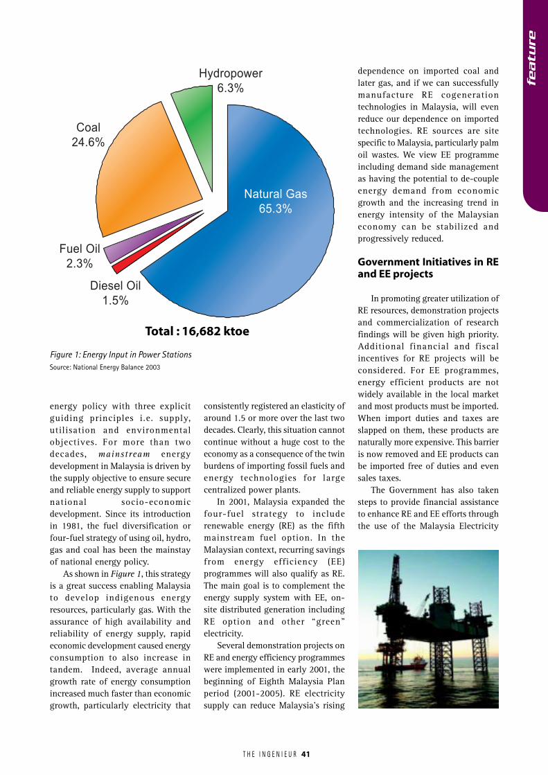
T H E I N G E N I E U R
featu
re
41
energy policy with three explicitguiding principles i.e. supply,utilisation and environmentalobjectives. For more than twodecades, mainstream energydevelopment in Malaysia is driven bythe supply objective to ensure secureand reliable energy supply to supportnational socio-economicdevelopment. Since its introductionin 1981, the fuel diversification orfour-fuel strategy of using oil, hydro,gas and coal has been the mainstayof national energy policy.
As shown in Figure 1, this strategyis a great success enabling Malaysiato develop indigenous energyresources, particularly gas. With theassurance of high availability andreliability of energy supply, rapideconomic development caused energyconsumption to also increase intandem. Indeed, average annualgrowth rate of energy consumptionincreased much faster than economicgrowth, particularly electricity that
consistently registered an elasticity ofaround 1.5 or more over the last twodecades. Clearly, this situation cannotcontinue without a huge cost to theeconomy as a consequence of the twinburdens of importing fossil fuels andenergy technologies for largecentralized power plants.
In 2001, Malaysia expanded thefour-fuel strategy to includerenewable energy (RE) as the fifthmainstream fuel option. In theMalaysian context, recurring savingsfrom energy efficiency (EE)programmes will also qualify as RE.The main goal is to complement theenergy supply system with EE, on-site distributed generation includingRE option and other “green”electricity.
Several demonstration projects onRE and energy efficiency programmeswere implemented in early 2001, thebeginning of Eighth Malaysia Planperiod (2001-2005). RE electricitysupply can reduce Malaysia’s rising
dependence on imported coal andlater gas, and if we can successfullymanufacture RE cogenerationtechnologies in Malaysia, will evenreduce our dependence on importedtechnologies. RE sources are sitespecific to Malaysia, particularly palmoil wastes. We view EE programmeincluding demand side managementas having the potential to de-coupleenergy demand from economicgrowth and the increasing trend inenergy intensity of the Malaysianeconomy can be stabilized andprogressively reduced.
Government Initiatives in REand EE projects
In promoting greater utilization ofRE resources, demonstration projectsand commercialization of researchfindings will be given high priority.Additional financial and fiscalincentives for RE projects will beconsidered. For EE programmes,energy efficient products are notwidely available in the local marketand most products must be imported.When import duties and taxes areslapped on them, these products arenaturally more expensive. This barrieris now removed and EE products canbe imported free of duties and evensales taxes.
The Government has also takensteps to provide financial assistanceto enhance RE and EE efforts throughthe use of the Malaysia Electricity
Hydropower
6.3%
Natural Gas
65.3%
Coal
24.6%
Fuel Oil
2.3%
Diesel Oil
1.5%
Figure 1: Energy Input in Power Stations
Total : 16,682 ktoe
Source: National Energy Balance 2003

T H E I N G E N I E U R 42
featu
re
Supply Industry Trust Account(MESITA). Major IPPs in PeninsularMalaysia including TNB Generationcontribute 1% of their audited annualrevenues to this trust account, ofwhich 20% could be allocated for REand EE activities.
To facilitate more utilization of REin power generation, the Governmentlaunched the Small Renewable EnergyProgramme (SREP) in 2001. Underthis programme, small powergeneration plants (10MW and under),which utilize RE, can apply to sell
electricity to TNB and SESB throughthe distribution system. EC has beenappointed as the secretariat, whichfunction as a One-Stop Centre, tofacilitate new investment in the SREP.
Future prospects andsustainability development
The Government fully subscribesto the concept of sustainabledevelopment. The concept of‘sustainability’ in the Malaysianenergy sector revolves around the
distribution and utilization of energyresources. Therefore, the primarychallenge for the energy sector is to:
� ensure adequate, secure, qualityand cost-effective supply ofenergy
� promote the efficient utilization ofenergy
� ensure minimum negative impacton the environment in the energysupply chain
As shown in Table 1 above, theGovernment has provided anallocation of RM2.6 billion only forthe energy sector in the 8MP period.However, investment expenditure byNon-Financial Public Enterprises(NFPEs) such as TNB, SESCo, SESBand PETRONAS is expected to reachRM 50.2 billion. In the 8MP, totalinvestments by the Government andNFPEs are reduced by 6.5% comparedto the amount spent in the 7MPperiod. It is expected that thesustainability of energy sectordevelopment can benefit from on-going initiatives to incorporate REand EE as mainstream energy optionsin the country.
Table 1: Development Allocation/Investments and Expenditure for Energy Sector Programmes,1995-2005 (RM million)
Source: The Eighth Malaysia Plan
Electricity Sector 2,543.6 23,563.6 26,107.2 2,601.6 22,565.1 25,166.7
Generation (hydro and thermal) 1,389.9 5,937.4 7,327.3 986.5 6,943.7 7,930.2Transmission 437.6 8,270.8 8,708.4 494.7 6,275.4 6,770.1Distribution 246.2 9,325.2 9,517.8 239.3 9,346.0 9,585.3Rural Electricity 463.6 - 463.6 856.6 - 856.6Others 6.3 30.2 36.5 24.5 - 24.5
Oil & Gas Sector - 30,400.0 30,400.0 - 27,638.0 27,638.0
Upstream - 12,900.0 12,900.0 - 12,800.0 12,800.0Downstream - 11,000.0 11,000.0 - 10,600.0 10,600.0Manufacturing - 5,300.0 5,300.0 - 2,200.0 2,200.0Others - 1,200.0 1,200.0 - 2,038.0 2,038.0
Total 2,543.6 53,963.6 56,507.2 2,601.6 50,203.1 52,804.7
Federal NFPEs Total Federal NFPEs TotalGovernment Government
7MP Expenditure 8MP AllocationProgramme
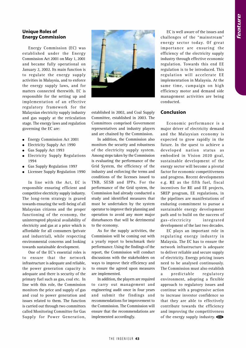
T H E I N G E N I E U R 43
Unique Roles ofEnergy Commission
Energy Commission (EC) wasestablished under the EnergyCommission Act 2001 on May 1, 2001and became fully operational onJanuary 2, 2002. Its main function isto regulate the energy supplyactivities in Malaysia, and to enforcethe energy supply laws, and formatters connected therewith. EC isresponsible for the setting up andimplementation of an effectiveregulatory framework for theMalaysian electricity supply industryand gas supply at the reticulationstage. The energy laws and regulationgoverning the EC are:
� Energy Commission Act 2001� Electricity Supply Act 1990� Gas Supply Act 1993� Electricity Supply Regulations
1994� Gas Supply Regulation 1997� Licensee Supply Regulation 1990
In line with the Act, EC isresponsible ensuring efficient andcompetitive electricity supply industry.The long-term strategy is gearedtowards ensuring the well-being of allMalaysian citizens and the properfunctioning of the economy, theuninterrupted physical availability ofelectricity and gas at a price which isaffordable for all consumers (privateand industrial), while respectingenvironmental concerns and lookingtowards sustainable development.
One of the EC’s essential roles isto ensure that the networkinfrastructure is adequate and reliable,the power generation capacity isadequate and there is security of theprimary fuel such as gas, coal etc. Inline with this role, the Commissionmonitors the price and supply of gasand coal to power generation andissues related to them. The functionis carried out through two committeescalled Monitoring Committee for GasSupply for Power Generation,
established in 2002, and Coal SupplyCommittee, established in 2003. TheCommittees comprised Governmentrepresentatives and industry playersand are chained by the Commission.
In addition, the Commission alsomonitors the security and robustnessof the electricity supply system.Among steps taken by the Commissionis evaluating the performance of theGrid System, the efficiency of theindustry and enforcing the terms andconditions of the licenses issued toTNB, SESB and IPPs. For theperformance of the Grid system, theCommission had already conducted astudy and identified measures thatmust be undertaken by the systemoperator to improve their planning andoperation to avoid any more majordisturbances that will be detrimentalto the economy.
As for the supply activities, theCommission will be coming out witha yearly report to benchmark theirperformance. Using the findings of thereport, the Commission will conductdiscussions with the stakeholders onways to improve their efficiency andto ensure the agreed upon measuresare implemented.
In addition, the players are requiredto carry out management andengineering audit once in four yearsand submit the findings andrecommendations for improvement tothe Commission. The Commission willensure that the recommendations areimplemented accordingly.
EC is well aware of the issues andchallenges of the “mainstream”energy sector today. Of greatimportance are ensuring theefficiency of the electricity supplyindustry through effective economicregulation. Towards this end EEregulation is to be introduced. Thisregulation wil l accelerate EEimplementation in Malaysia. At thesame time, campaign on highefficiency motor and demand sidemanagement activities are beingconducted.
Conclusion
Economic performance is amajor driver of electricity demandand the Malaysian economy isexpected to grow rapidly in thefuture. In the quest to achieve adeveloped nation status asembodied in Vision 2020 goal,sustainable development of theenergy sector will become a pivotalfactor for economic competitivenessand progress. Recent developmentse.g. RE as the fifth fuel, fiscalincentives for RE and EE projects,SREP program, EE regulations, inthe pipelines are manifestations ofenduring commitment to pursue asustainable energy developmentpath and to build on the success ofgas–electricity integrateddevelopment of the last two decades.
EC plays an important role inregulating energy industry inMalaysia. The EC has to ensure thenetwork infrastructure is adequateto deliver reliable and secure supplyof electricity. Energy pricing issuesneed to be analysed continuously.The Commission must also establisha predictable regulatoryenvironment, adopting a flexibleapproach to regulatory issues andcontinue with a progressive actionto increase investor confidence sothat they are able to effectivelycontribute towards the efficiencyand improving the competitivenessof the energy supply industry. BEM
featu
re
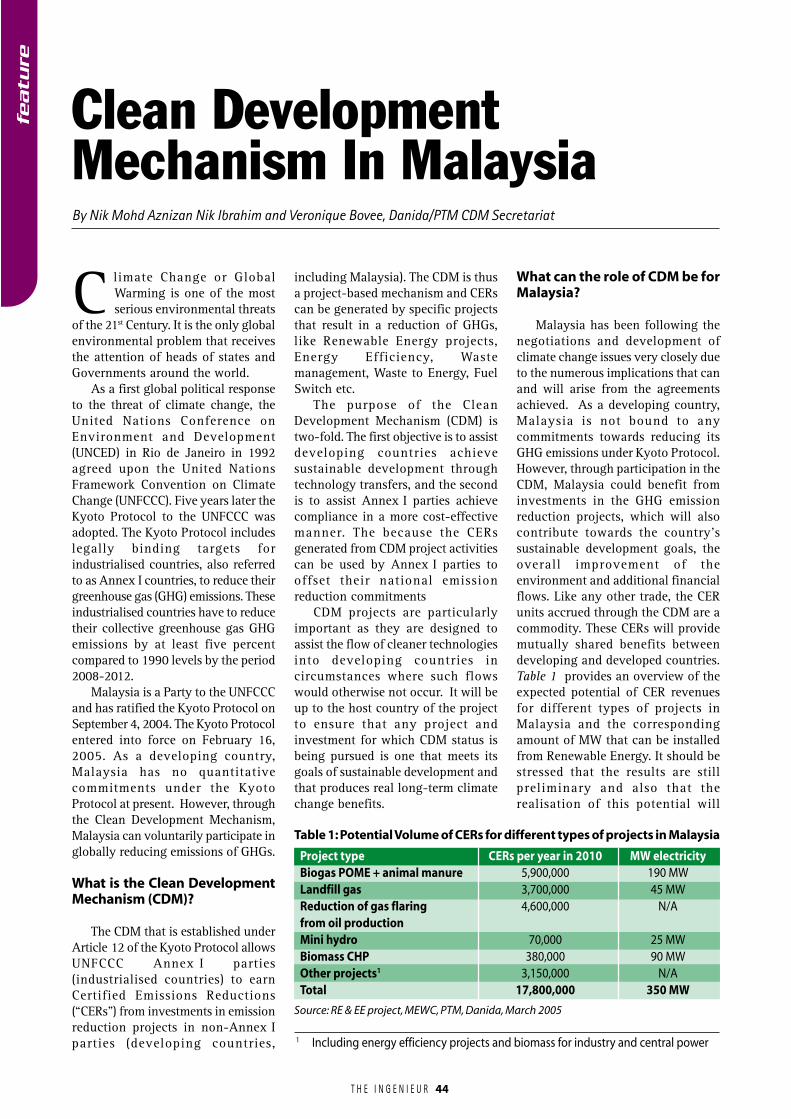
T H E I N G E N I E U R 44
By Nik Mohd Aznizan Nik Ibrahim and Veronique Bovee, Danida/PTM CDM Secretariat
Clean DevelopmentMechanism In Malaysia
C limate Change or GlobalWarming is one of the mostserious environmental threats
of the 21st Century. It is the only globalenvironmental problem that receivesthe attention of heads of states andGovernments around the world.
As a first global political responseto the threat of climate change, theUnited Nations Conference onEnvironment and Development(UNCED) in Rio de Janeiro in 1992agreed upon the United NationsFramework Convention on ClimateChange (UNFCCC). Five years later theKyoto Protocol to the UNFCCC wasadopted. The Kyoto Protocol includeslegally binding targets forindustrialised countries, also referredto as Annex I countries, to reduce theirgreenhouse gas (GHG) emissions. Theseindustrialised countries have to reducetheir collective greenhouse gas GHGemissions by at least five percentcompared to 1990 levels by the period2008-2012.
Malaysia is a Party to the UNFCCCand has ratified the Kyoto Protocol onSeptember 4, 2004. The Kyoto Protocolentered into force on February 16,2005. As a developing country,Malaysia has no quantitativecommitments under the KyotoProtocol at present. However, throughthe Clean Development Mechanism,Malaysia can voluntarily participate inglobally reducing emissions of GHGs.
What is the Clean DevelopmentMechanism (CDM)?
The CDM that is established underArticle 12 of the Kyoto Protocol allowsUNFCCC Annex I parties(industrialised countries) to earnCertified Emissions Reductions(“CERs”) from investments in emissionreduction projects in non-Annex Iparties (developing countries,
including Malaysia). The CDM is thusa project-based mechanism and CERscan be generated by specific projectsthat result in a reduction of GHGs,like Renewable Energy projects,Energy Efficiency, Wastemanagement, Waste to Energy, FuelSwitch etc.
The purpose of the CleanDevelopment Mechanism (CDM) istwo-fold. The first objective is to assistdeveloping countries achievesustainable development throughtechnology transfers, and the secondis to assist Annex I parties achievecompliance in a more cost-effectivemanner. The because the CERsgenerated from CDM project activitiescan be used by Annex I parties tooffset their national emissionreduction commitments
CDM projects are particularlyimportant as they are designed toassist the flow of cleaner technologiesinto developing countries incircumstances where such flowswould otherwise not occur. It will beup to the host country of the projectto ensure that any project andinvestment for which CDM status isbeing pursued is one that meets itsgoals of sustainable development andthat produces real long-term climatechange benefits.
What can the role of CDM be forMalaysia?
Malaysia has been following thenegotiations and development ofclimate change issues very closely dueto the numerous implications that canand will arise from the agreementsachieved. As a developing country,Malaysia is not bound to anycommitments towards reducing itsGHG emissions under Kyoto Protocol.However, through participation in theCDM, Malaysia could benefit frominvestments in the GHG emissionreduction projects, which will alsocontribute towards the country’ssustainable development goals, theoverall improvement of theenvironment and additional financialflows. Like any other trade, the CERunits accrued through the CDM are acommodity. These CERs will providemutually shared benefits betweendeveloping and developed countries.Table 1 provides an overview of theexpected potential of CER revenuesfor different types of projects inMalaysia and the correspondingamount of MW that can be installedfrom Renewable Energy. It should bestressed that the results are stillpreliminary and also that therealisation of this potential will
Table 1: Potential Volume of CERs for different types of projects in Malaysia
Source: RE & EE project, MEWC, PTM, Danida, March 2005
Project type CERs per year in 2010 MW electricityBiogas POME + animal manure 5,900,000 190 MWLandfill gas 3,700,000 45 MWReduction of gas flaring 4,600,000 N/Afrom oil productionMini hydro 70,000 25 MWBiomass CHP 380,000 90 MWOther projects1 3,150,000 N/ATotal 17,800,000 350 MW
1 Including energy efficiency projects and biomass for industry and central power
featu
re
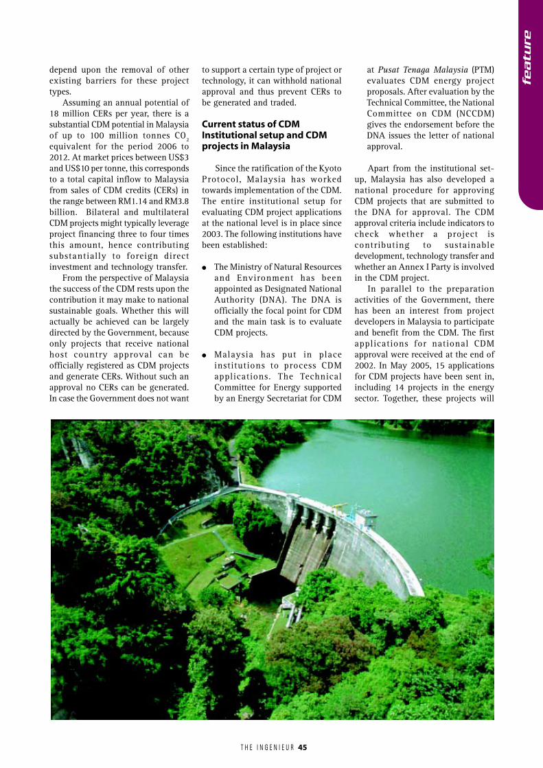
T H E I N G E N I E U R
featu
re
45
depend upon the removal of otherexisting barriers for these projecttypes.
Assuming an annual potential of18 million CERs per year, there is asubstantial CDM potential in Malaysiaof up to 100 million tonnes CO2equivalent for the period 2006 to2012. At market prices between US$3and US$10 per tonne, this correspondsto a total capital inflow to Malaysiafrom sales of CDM credits (CERs) inthe range between RM1.14 and RM3.8billion. Bilateral and multilateralCDM projects might typically leverageproject financing three to four timesthis amount, hence contributingsubstantially to foreign directinvestment and technology transfer.
From the perspective of Malaysiathe success of the CDM rests upon thecontribution it may make to nationalsustainable goals. Whether this willactually be achieved can be largelydirected by the Government, becauseonly projects that receive nationalhost country approval can beofficially registered as CDM projectsand generate CERs. Without such anapproval no CERs can be generated.In case the Government does not want
to support a certain type of project ortechnology, it can withhold nationalapproval and thus prevent CERs tobe generated and traded.
Current status of CDMInstitutional setup and CDMprojects in Malaysia
Since the ratification of the KyotoProtocol, Malaysia has workedtowards implementation of the CDM.The entire institutional setup forevaluating CDM project applicationsat the national level is in place since2003. The following institutions havebeen established:
� The Ministry of Natural Resourcesand Environment has beenappointed as Designated NationalAuthority (DNA). The DNA isofficially the focal point for CDMand the main task is to evaluateCDM projects.
� Malaysia has put in placeinstitutions to process CDMapplications. The TechnicalCommittee for Energy supportedby an Energy Secretariat for CDM
at Pusat Tenaga Malaysia (PTM)evaluates CDM energy projectproposals. After evaluation by theTechnical Committee, the NationalCommittee on CDM (NCCDM)gives the endorsement before theDNA issues the letter of nationalapproval.
Apart from the institutional set-up, Malaysia has also developed anational procedure for approvingCDM projects that are submitted tothe DNA for approval. The CDMapproval criteria include indicators tocheck whether a project iscontributing to sustainabledevelopment, technology transfer andwhether an Annex I Party is involvedin the CDM project.
In parallel to the preparationactivities of the Government, therehas been an interest from projectdevelopers in Malaysia to participateand benefit from the CDM. The firstapplications for national CDMapproval were received at the end of2002. In May 2005, 15 applicationsfor CDM projects have been sent in,including 14 projects in the energysector. Together, these projects will
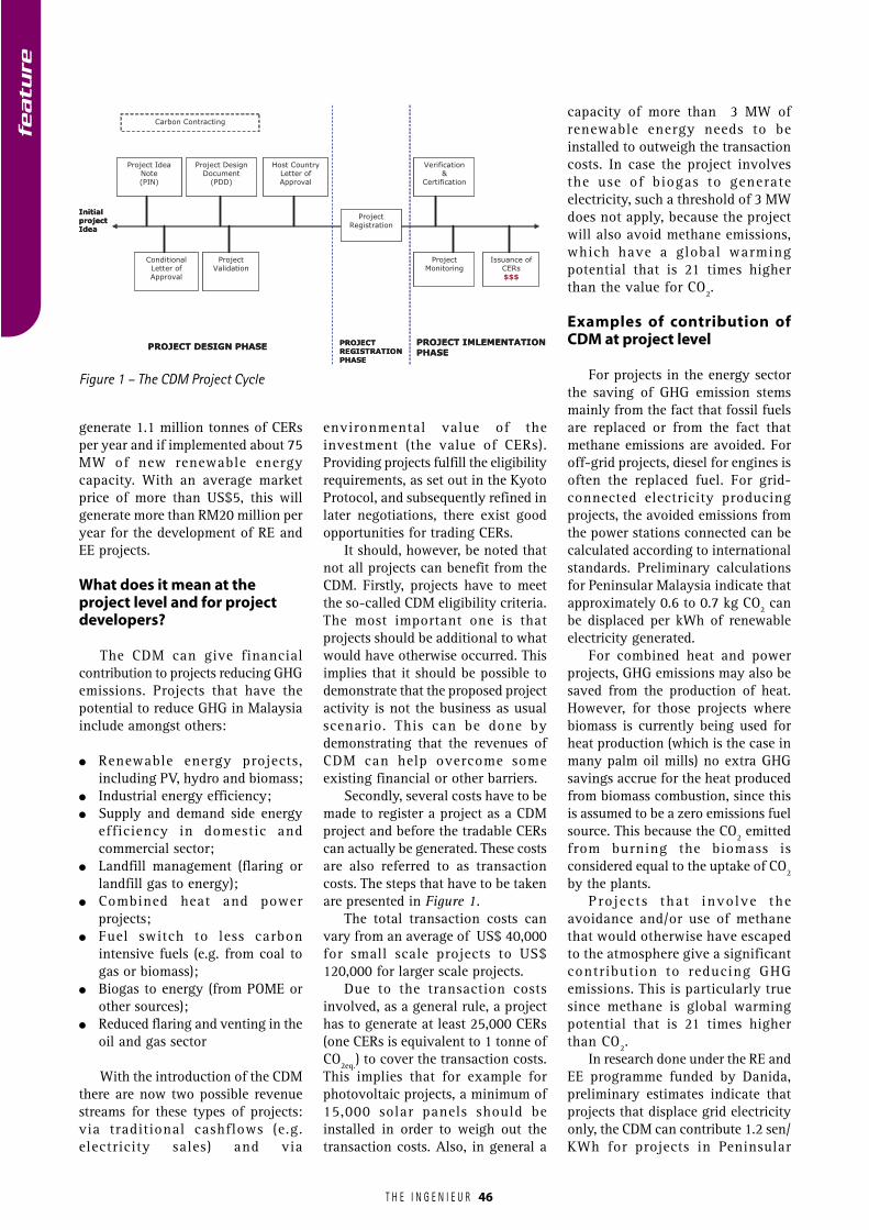
T H E I N G E N I E U R 46
featu
re
generate 1.1 million tonnes of CERsper year and if implemented about 75MW of new renewable energycapacity. With an average marketprice of more than US$5, this willgenerate more than RM20 million peryear for the development of RE andEE projects.
What does it mean at theproject level and for projectdevelopers?
The CDM can give financialcontribution to projects reducing GHGemissions. Projects that have thepotential to reduce GHG in Malaysiainclude amongst others:
� Renewable energy projects,including PV, hydro and biomass;
� Industrial energy efficiency;� Supply and demand side energy
efficiency in domestic andcommercial sector;
� Landfill management (flaring orlandfill gas to energy);
� Combined heat and powerprojects;
� Fuel switch to less carbonintensive fuels (e.g. from coal togas or biomass);
� Biogas to energy (from POME orother sources);
� Reduced flaring and venting in theoil and gas sector
With the introduction of the CDMthere are now two possible revenuestreams for these types of projects:via traditional cashflows (e.g.electricity sales) and via
environmental value of theinvestment (the value of CERs).Providing projects fulfill the eligibilityrequirements, as set out in the KyotoProtocol, and subsequently refined inlater negotiations, there exist goodopportunities for trading CERs.
It should, however, be noted thatnot all projects can benefit from theCDM. Firstly, projects have to meetthe so-called CDM eligibility criteria.The most important one is thatprojects should be additional to whatwould have otherwise occurred. Thisimplies that it should be possible todemonstrate that the proposed projectactivity is not the business as usualscenario. This can be done bydemonstrating that the revenues ofCDM can help overcome someexisting financial or other barriers.
Secondly, several costs have to bemade to register a project as a CDMproject and before the tradable CERscan actually be generated. These costsare also referred to as transactioncosts. The steps that have to be takenare presented in Figure 1.
The total transaction costs canvary from an average of US$ 40,000for small scale projects to US$120,000 for larger scale projects.
Due to the transaction costsinvolved, as a general rule, a projecthas to generate at least 25,000 CERs(one CERs is equivalent to 1 tonne ofCO2eq.) to cover the transaction costs.This implies that for example forphotovoltaic projects, a minimum of15,000 solar panels should beinstalled in order to weigh out thetransaction costs. Also, in general a
capacity of more than 3 MW ofrenewable energy needs to beinstalled to outweigh the transactioncosts. In case the project involvesthe use of biogas to generateelectricity, such a threshold of 3 MWdoes not apply, because the projectwill also avoid methane emissions,which have a global warmingpotential that is 21 times higherthan the value for CO2.
Examples of contribution ofCDM at project level
For projects in the energy sectorthe saving of GHG emission stemsmainly from the fact that fossil fuelsare replaced or from the fact thatmethane emissions are avoided. Foroff-grid projects, diesel for engines isoften the replaced fuel. For grid-connected electricity producingprojects, the avoided emissions fromthe power stations connected can becalculated according to internationalstandards. Preliminary calculationsfor Peninsular Malaysia indicate thatapproximately 0.6 to 0.7 kg CO2 canbe displaced per kWh of renewableelectricity generated.
For combined heat and powerprojects, GHG emissions may also besaved from the production of heat.However, for those projects wherebiomass is currently being used forheat production (which is the case inmany palm oil mills) no extra GHGsavings accrue for the heat producedfrom biomass combustion, since thisis assumed to be a zero emissions fuelsource. This because the CO2 emittedfrom burning the biomass isconsidered equal to the uptake of CO2by the plants.
Projects that involve theavoidance and/or use of methanethat would otherwise have escapedto the atmosphere give a significantcontribution to reducing GHGemissions. This is particularly truesince methane is global warmingpotential that is 21 times higherthan CO2.
In research done under the RE andEE programme funded by Danida,preliminary estimates indicate thatprojects that displace grid electricityonly, the CDM can contribute 1.2 sen/KWh for projects in Peninsular
Project Idea Note(PIN)
Initial project Idea
Conditional Letter of Approval
Carbon Contracting
Project Design Document
(PDD)
Project Validation
Host Country Letter of Approval
Project Registration
Project Monitoring
Verification&
Certification
Issuance of CERs$$$
PROJECT DESIGN PHASEPROJECT REGISTRATIONPHASE
PROJECT IMLEMENTATIONPHASE
Figure 1 – The CDM Project Cycle
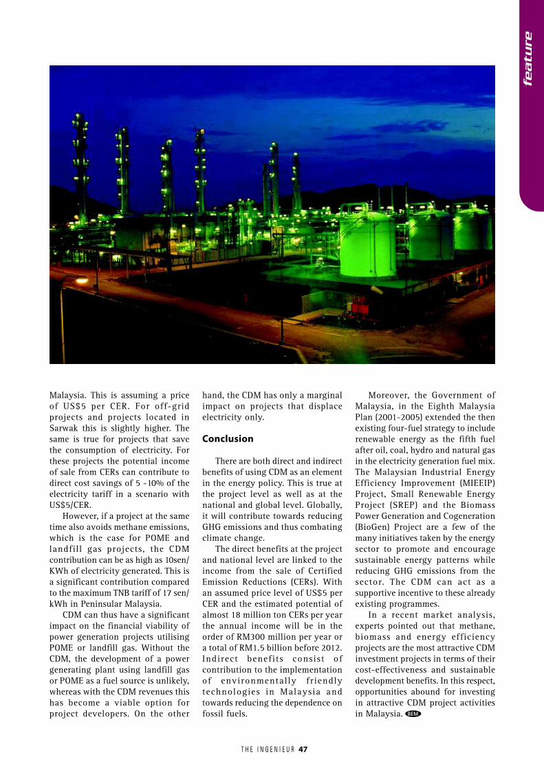
T H E I N G E N I E U R
Malaysia. This is assuming a priceof US$5 per CER. For off-gridprojects and projects located inSarwak this is slightly higher. Thesame is true for projects that savethe consumption of electricity. Forthese projects the potential incomeof sale from CERs can contribute todirect cost savings of 5 -10% of theelectricity tariff in a scenario withUS$5/CER.
However, if a project at the sametime also avoids methane emissions,which is the case for POME andlandfill gas projects, the CDMcontribution can be as high as 10sen/KWh of electricity generated. This isa significant contribution comparedto the maximum TNB tariff of 17 sen/kWh in Peninsular Malaysia.
CDM can thus have a significantimpact on the financial viability ofpower generation projects utilisingPOME or landfill gas. Without theCDM, the development of a powergenerating plant using landfill gasor POME as a fuel source is unlikely,whereas with the CDM revenues thishas become a viable option forproject developers. On the other
hand, the CDM has only a marginalimpact on projects that displaceelectricity only.
Conclusion
There are both direct and indirectbenefits of using CDM as an elementin the energy policy. This is true atthe project level as well as at thenational and global level. Globally,it will contribute towards reducingGHG emissions and thus combatingclimate change.
The direct benefits at the projectand national level are linked to theincome from the sale of CertifiedEmission Reductions (CERs). Withan assumed price level of US$5 perCER and the estimated potential ofalmost 18 million ton CERs per yearthe annual income will be in theorder of RM300 million per year ora total of RM1.5 billion before 2012.Indirect benefits consist ofcontribution to the implementationof environmentally fr iendlytechnologies in Malaysia andtowards reducing the dependence onfossil fuels.
Moreover, the Government ofMalaysia, in the Eighth MalaysiaPlan (2001-2005) extended the thenexisting four-fuel strategy to includerenewable energy as the fifth fuelafter oil, coal, hydro and natural gasin the electricity generation fuel mix.The Malaysian Industrial EnergyEfficiency Improvement (MIEEIP)Project, Small Renewable EnergyProject (SREP) and the BiomassPower Generation and Cogeneration(BioGen) Project are a few of themany initiatives taken by the energysector to promote and encouragesustainable energy patterns whilereducing GHG emissions from thesector. The CDM can act as asupportive incentive to these alreadyexisting programmes.
In a recent market analysis,experts pointed out that methane,biomass and energy efficiencyprojects are the most attractive CDMinvestment projects in terms of theircost-effectiveness and sustainabledevelopment benefits. In this respect,opportunities abound for investingin attractive CDM project activitiesin Malaysia. BEM
47
featu
re
T H E I N G E N I E U R 48
The Coming Of EurocodesBy Ir. Albert K W Tam, Pemborong Pembenaan Tam Kan Sdn Bhd
This article serves to give a brief view of the historical background and the development of Eurocodes.For more technical details, the reader is advised to search on the Internet for which there are a fewweb sites dedicated to this subject. A couple of short technical papers on Eurocode 2 had also beenpublished in the monthly bulletin of the IEM over the last three years.
As part of the European Union’s desire to do away with technical barriers to trade, a set of EuropeanCodes of Practice in civil and structural engineering is progressively being published. The main purposeof the Eurocodes is to provide a common platform for design criteria and methods; with a commonunderstanding of structural design between owners, users, designers, contractors and material andproduct manufactures. It also permits the standardization in the preparation and development ofsoftware and design aids. Ultimately, this will enhance and increase the global competitiveness oftheir structural engineering consultants, contractors, product manufacturers and suppliers.
The coming of Eurocodes will eventually affect the engineers and the engineering industries in Malaysiain many ways. The Malaysian engineering community must set its sight in the right direction and gearup early to meet this new challenge.
Europe has seen some of the bloodiest wars over aperiod of 75 years from 1870 to1945 where Franceand Germany, with their allies fought each other to
devastating effect. After the two great wars a number ofEuropean leaders came to the noble believe that the onlyway to secure a lasting peace between their countries wasto unite them economically and politically.
Thus, with this purpose in mind in 1951, the ECSC(European Coal and Steel Community) was set up withsix member states: Belgium, West Germany, Luxembourg,France, Italy and the Netherlands. The ECSC was such asuccess that, within a few years, the same six countriesdecided to go one-step further and integrate other sectorsof their economies.
In 1957, they signed the Treaties of Rome, creatingthe European Economic Community (EEC) or morecommonly known as the “Common Market”, thus settingthe ball rolling on the removal of trade barriers betweenthem.
Since then this union of states has became the EU(European Union) and has grown in size followingsuccessive waves of accessions. Denmark, Ireland and theUnited Kingdom joined in 1973, followed by Greece in1981, Spain and Portugal in 1986 and Austria, Finlandand Sweden in 1995.
The EU has just welcomed a further ten new memberstates from the eastern and southern Europe in 2004:Cyprus, the Czech Republic, Estonia, Hungary, Latvia,Lithuania, Malta, Poland, Slovakia and Slovenia. This is
by far the biggest enlargement symbolizing a new EUand a new Europe.
Bulgaria and Romania are expected to follow a fewyears later with Turkey closely behind.
Economic and political integration between memberstates of the EU has meant that these countries have tomake joint decisions on many internal and internationalmatters. Accordingly, they have developed common policiesin a wide range of matters - from agriculture to culture,from consumer affairs to competition and from theenvironment to engineering, transport and trade.
To ensure that the EU can continue to function efficientlywith 25 or more member states, the decision-making systemhas been streamlined into EU institutions under the Treatyof Nice. The Treaty lays down new rules governing the sizeof the EU institutions and the way they work. It came intoforce on 1st February 2003.
The EU has seen almost half a century of stability, peaceand prosperity. It has undoubtedly helped to raise the livingstandards, built a single Europe-wide market, launched thesingle Euro currency and strengthened Europe’s voice inthe world. This harmonization process has great implicationon world affairs and affected one way or another, the well-being of individuals in a great number of countries.
There have been three important developments in theEU, which are affecting the practice and profession ofengineering, and its direction in years to come. Of thesethree, the last would have the most influence on engineeringpractices in Malaysia.
featu
re
T H E I N G E N I E U R
featu
re
49
1. The formation of Fédération Européene d’AssociationsNationales d’Ingénieurs (FEANI) in 1951 as afederation of professional engineers that unitesnational or professional engineering associationsfrom 26 European countries. FEANI represents theinterests of well over 2 million professional engineersin Europe and has since strived for a single voice forthe engineering profession in Europe.
Through its activities and services, especially withthe attribution of the Eur Ing professional title, FEANIaims to secure the mutual recognition of all Europeanengineering titles and qualifications, to strengthenthe position, role and responsibility of engineers insociety and to facilitate the freedom of engineers tomove and practice within and outside Europe
The law in the UK protects the use of the title Eur Ingas a prenominal in front of the name and before allother ranks and titles. The Eur Ing registration andthe use of the designation are regarded as a guaranteeof competence for professional engineers.
2. The introduction of a single European currency (theEuro) on 1st January 2002 to effect economic andmonetary union (EMU) within the EU. From that daythe Euros is managed by a European Central Bank.Euro notes and coins had replaced national currenciesin twelve of the 15 countries of the EU (Belgium,Germany, Greece, Spain, France, Ireland, Italy,Luxembourg, the Netherlands, Austria, Portugal andFinland).
3. The introduction of unified international codes ofpractice in particular the structural Eurocodes for thedesign of buildings and civil engineering structures,which will replace national codes in the EuropeanCommunity.
Eurocodes – What Are They?
Eurocodes or more precisely Structural Eurocodes area new set of unified international codes of practiceconsisting of nine EN (European Standards) covering theuse of common structural materials, design and practicecodes for the design of buildings and civil engineeringstructures. They are primarily designed to improve andstreamline the European construction industry to be morecompetitive and enhance structural safety and theprofessionals and related industries connected with it. Theyare applicable to whole structures and to individualcomponent or elements of structures taking intoconsideration all the advances made in the developmentand production of and the use of all major constructionmaterials including concrete, steel, aluminum, timber andmasonry.
The Eurocodes are mandatory for European publicworks and are set to become the de-facto standard for theprivate sector. They will become the EU member countries’
vital means of designing Civil and Structural engineeringworks and are of utmost importance and significance toboth the design and construction sectors of the Civil andBuilding Industries in Europe. Like other Europeanstandards in use in EU countries today, Eurocodes willalso be used to assess products for “CE” (ConformiteEuropean) mark. The adoption of the structural Eurocodesby EU countries has wide implications on the Civil andBuilding industries in Europe and other countriesworldwide. This is because about half the countries in theworld has historical background and connections withthe EU countries.
The Eurocodes are:
EuroNorm Reference
EN 1990 Eurocode 0 : Basis of structural designEN 1991 Eurocode 1 : Actions on structuresEN 1992 Eurocode 2 : Design of concrete structuresEN 1993 Eurocode 3 : Design of steel structuresEN 1994 Eurocode 4 : Design of composite steel and
concrete structuresEN 1995 Eurocode 5 : Design of timber structuresEN 1996 Eurocode 6 : Design of masonry structuresEN 1997 Eurocode 7 : Geotechnical designEN 1998 Eurocode 8 : Design of structures for
earthquake resistanceEN 1999 Eurocode 9 : Design of aluminium structures
The complete suite of structural Eurocodes is underthe purview and management of CEN (EuropeanCommittee for Standardisation). Currently 20 CENmembers representing their national standards bodies ofthe EU and EFTA countries including the Czech Republicand Malta are involved in the production.
The work of drafting the Eurocodes was originallyunder the aegis of the European Commission, but waslater transferred to CEN as the official European Standardsbody. The history of Eurocodes therefore must go back to1990 when the Technical Committee CEN/TC 250“Structural Eurocodes” was charged with the responsibilityof developing the Eurocodes, first as the European Pre-standards (ENV) and later as the European Standards (EN).One might also ask why use the number 1990 as start ofEuroNorm References. One supposes that EN 1990 is mostappropriate as everything began earnest in Year 1990.
As of late last year, the whole suite of 62 ENV isavailable for comment by member states. At present, planis at hand to convert 54 of the 62 ENV into 57 parts ofthe EN – Eurocodes, covering Actions, Steel, Concrete,Composite Steel and Concrete, Timber, Masonry andAluminium, together with Geotechnical design and Seismicdesign.
The period for the publication of the 10 EN Eurocodesis scheduled between Year 2002 and Year 2005. As soonas an EN Eurocode is published, the period of co-existencecommences between that published EN Eurocode and thecorresponding national codes. They will eventually replace
T H E I N G E N I E U R 50
featu
re
the national codes published by respective nationalstandard bodies or institutions like the BSI (BritishStandards Institution) in the UK. It is anticipated that mostEuropean national codes will cease to be in use by Year2007. In the UK withdrawal of most if not all the BritishStandards is certain to take effect by 2007 to 2010.
The first two of the converted Eurocodes (EN 1990and EN 1991), covering the Basis of Structural Designand Actions due to self-weight and imposed loads, havebeen published during 2002, having successfully passedthrough the CEN procedures.
The Objectives Of Eurocodes
As mentioned earlier the main purpose of the Eurocodesis to improve the international competitiveness of all theEuropean construction industry and the engineeringprofessionals and industries connected with it both withinthe European Union and outside its borders.
The introduction of a common suite of Eurocodes inEU will make the practice of engineering, manufacturingand the profession so much less complicated across bordersof member states.
Other benefits and opportunities brought about by theadoption of the Eurocodes include:
� the provision of better understanding of design ofstructures between owners, and users, designers,contractors and manufacturers of constructionmaterials and products.
� to facilitate the exchange of construction servicesbetween member states.
� to facilitate the marketing and usage of structuralcomponents and parts in member states and othercountries.
� the adoption of a common basis for higher educationof learning, research and development in theconstruction sector.
� provide a strong incentive for the preparation,development and marketing of common design andconstruction aids and softwares.
� increase the competitiveness of the European civiland structural engineering firms, consultants,contractors, designers and product manufacturers intheir worldwide activities.
National Annexes
While so much so has been said about Eurocodes, avery important but vital distinction must be made at thispoint between the design codes and national regulationsand public authority requirements.
From the outset in the drafting and preparation ofEurocodes member EU states have recognized that safetymust ultimately remain a national and not a Europeanresponsibility. The safety factors outlined in the Eurocodesare only the recommended values and that they may bealtered by the national competent authority of eachmember state as deemed fit and proper.
This has involved the introduction of some flexibility,across border, by means of what are commonly known asNDPs (Nationally Determined Parameters). Each part ofthe Eurocode will include a NA (National Annex) givingnational values for certain partial safety factors or NDPs.The NA may include national practice and local or climaticconditions (winds etc), classes, methods, level of safety,durability, different levels of protection and economyapplicable to certain types of work.
In UK, the British Standards Institution (BSI) is thenational standard body responsible for publishing thestructural Eurocodes as the new national standards. Othernational standard bodies will do likewise. Authorizationfor use of the Eurocodes will rest with the respectivenational competent authority.
The national standard body will be bound to publishthe structural Eurocodes and its annexes in full withoutany alterations as published by the CEN. However, thiswill be preceded by a national title page and a nationalforeword and followed by a national annex NA.
Eurocodes In Brief
The European Commission formally recommended theEurocodes as ‘a suitable tool’ for designing constructionworks, checking the mechanical resistance of componentsand checking the stability of structures videRecommendation 4639 of 11th December 2003. Henceforth,all member states should recognize construction worksdesigned using Eurocodes.
The Commission has also warned member states thatthey should only diverge from recommended values inEurocodes when ‘geographical, geological or climaticconditions or specific levels of protection make thatnecessary’. EU member states diverging too far fromrecommended values will be told to change their nationallydetermined parameters.
A very general brief is presented below for eachstructural Eurocode
EN 1990 Eurocode 0: Basis of structural design(Published 2002)
This is the head document in the suit of Eurocodesand outlines the principles and requirements for safety,serviceability and durability of structures. EN 1990 is basedon the limit state concept in conjunction with a partialfactor method and provides the basis and general principlesfor the structural design verification of civil engineeringand building works. EN 1990 must be used in conjunctionwith EN 1991 to EN 1999 as within them they do notprovide material independent guidance.
In EN 1990, the basic principles of structural designhave been harmonized for the EU member states includingsuch use of principle construction materials and disciplinesof engineering. Principal construction materials includeconcrete, steel, masonry, timber and aluminium butexcluding glass. Engineering disciplines covergeotechnical, bridge design, fire and earthquake etc.
T H E I N G E N I E U R
featu
re
51
EN 1991 Eurocode 1: Actions on structures (Published 2002)
EN 1991 provides comprehensive information andguidelines on all actions that should be considered in thedesign of buildings and civil engineering works.
Subjects covered include densities, self-weight,imposed loads, actions due to fire, snow and wind, thermalactions, loads during execution and accidental actions.
Other main area covered includes traffic loads onbridges, actions by cranes and machinery and actions insilos and tanks.
EN 1992 Eurocode 2: Design of concrete structures(Imminent release in 2005)
Eurocode 2 will become the only one design code forall concrete structures in UK and Europe. It is by far morecomprehensive since it has brought reinforced concretedesign up to date reaping past experience of over 40 yearsof UK ultimate limit state design codes BS 8110 and BS8007.
Eurocode 2 will ultimately replace the following BSStandards.
BS 5400 for BridgesBS 6349 for Maritime StructuresBS 8007 for Water-Retaining StructuresBS 8110 for Buildings
Eurocode 2 has four parts giving comprehensiveinformation for the design of concrete buildings and civilengineering works and having the following references.
EN1992-1-1 Common rules for buildings and civilengineering structuresThis covers common design rules.
EN1992-1-2 Structural fire designThis covers design requirementsfor fire.
EN1992-2 BridgesThis covers the design of bridges.
EN1992-3 Liquid-retaining structuresThis covers the design of liquid-retainingstructures.
Eurocode 2 depends on Eurocode 1 for loads. In thedesign process various partial factors are to be applied tothe loads according to the limit state under consideration.The values of various partial factors are contained inEurocode 0, as confirmed or modified by the relevantNational Annex.
As EN1992 Eurocode 2 will be the most widely useddocument of design engineer, there is now at hand anumber of guidance notes to help comprehension of thecode. These can be downloaded from a web site atwww.eurocode2.info/EC2wpintro_files/EC2wpEC2-2.htm.
The guidance notes available include the following:
� Practical use of Eurocode 2� EC2 versus BS8110� How to design beams to EC2� How to design solid slabs to EC2� How to design columns and walls to EC2� How to design flat slabs to EC2� Guidance on deflection� EC2 design flowcharts� Basic design equations� Guide to concrete cover and concrete quality
EN 1993 Eurocode 3: Design of steel structures
More advanced and new methods for the design of agreater numbers of steel structures when compared toexisting British Standards are included in EN 1993Eurocode 3. Both bolted and welded joints, rules for shelland for the design of piles, sheet piling, silos, bridges,buildings, tanks, crane supported structures, towers andmasts are explained in various sections. Rules for stainlesssteel are now included.
EN 1994 Eurocode 4: Design of composite steel andconcrete structures
EN 1994 covers the common rules for buildings,structural fire design and bridges. EN 1994 will need tobe used in conjunction with EN 1992 Eurocode 2: Designof concrete structures and EN 1993 Eurocode 3: Designof steel structures.
EN 1995 Eurocode 5: Design of timber structures
EN 1995 Eurocode 5 covers the common rules andrules for the design of buildings, structural fire designand bridges. EN 1995 uses the limit state design conceptand is performance based. This is unlike the BritishStandards for timber which uses the permissible stressmethod.
EN 1995 will require software assistance for the designer.
EN 1996 Eurocode 6: Design of masonry structures
EN 1996 covers the design rules for reinforced andunreinforced masonry, structural fire design and rules forlateral loading for masonry structures.
EN 1997 Eurocode 7: Geotechnical design
EN 1997 Eurocode 7 has three parts.
Part 1: General Rules has the following sub-headings.1: General2: Basis of geotechnical design3: Geotechnical data4: Supervision of construction, monitoring and
maintenance
T H E I N G E N I E U R 52
featu
re
5: Fill, dewatering, ground improvementand reinforcement
6: Spread foundations7: Pile foundations8: Anchorages9: Retaining structures10: Hydraulic failures11: Overall stability12: Embankments
Annexes
Part 2: Design assisted by laboratory testingThis covers the requirements for the execution,interpretation and use of the results of thelaboratory tests to assist in the geotechnicaldesign of structures, buildings and civilengineering works.
Part 3: Design assisted by field testingThis covers the requirements for the execution,interpretation and use of the results of the fieldtests to assist in the geotechnical design ofstructures.
EN 1998 Eurocode 8: Design of structures for earthquakeresistance
EN 1998 covers the general rules for the design ofstructures for earthquake resistance including seismicactions and rules for buildings, bridges, strengthening andrepair of buildings, silos, tanks, pipelines, towers, masts,chimneys, foundations and retaining structures.
EN 1999 Eurocode 9: Design of aluminium structures
EN 1999 covers the common rules, structural fire designand fatigue of structures.
Need For Continued Education, Training AndProfessional Development
From the UK experiences and feedback it is generallyaccepted that both civil and structural designers will haveto undergo a substantial amount of retraining coupledwith new supporting guidance notes, handbooks andsoftware for the successful implementation of Eurocodes.There will be definitely a learning curve to follow and thequality of such learning will depend very much on thetime, amount of available resources and dedication offeredby individual, companies, organizations and governmentalauthorities.
The development and usage of appropriate software isnow deemed a higher priority as several Eurocodes willrequire programmed software assistance.
Universities and other institutions of higher learningwill also need to remold their courses to meet this newchallenge.
As a part of this effort, Eurocodes Expert has beenestablished by the Institution of Civil Engineers UK,
Thomas Telford and various other UK construction industrybodies to provide a vehicle for communicatingdevelopments and guidance on the Eurocodes throughoutEurope. A great amount of up-to-date information anddata can be readily accessed from their web site atwww.eurocodes.co.uk. There is also a free Users’ Groupand newsletter for ICE members and other associatedlearned bodies. The same site also provides a platform forthe reader to seek further information on all publications,events and courses relating to Eurocodes.
Various conference and training programmes are beingdeveloped by institutions and industry bodies in the UKand elsewhere to help the construction industry adoptand use the Eurocodes.
Malaysia’s Direction Amidst Winds Of Change
Because of the historical background of many non-EU countries with most European countries in politics,commerce, education and trade, the introduction ofEurocodes in the EU will also have great implication innon-EU countries.
The effect of Eurocodes on individual countries, likeMalaysia, Singapore and Hong Kong are now being studiedin earnest by their respective engineering profession.Efforts are now being made to increase the awareness ofthe engineers and in the industry on the differencesbetween Eurocodes and British Standards or equivalentlocal standards, which the local construction industry isheavily relied upon.
Eurocodes are considered international standards andmay ultimately be adopted by the ISO. Because of theWTO agreement, member countries will see greateradvantages in adopting Eurocodes.
Perhaps it is now an opportune time for Malaysianengineers and the Malaysian construction industry as awhole to harmonize their design standards with rest ofthe world and to reap this new opportunity in the horizon.
To this end, the Institution of Engineers Malaysia (IEM)has taken an early step in monitoring the situation closely.A Position-Paper Committee was formed in July 2001 bythe Civil and Structural Engineering Technical Divisionof IEM, to study the impact of the withdrawal of the BritishStandards and Code of Practices after year 2007 on thelocal construction industry. However, this study isrestricted only to Eurocode 2 as compared to BS 8110 andnot any other Eurocodes.
The Position Paper Committee studied on two possiblescenarios, which can be foreseen, in the withdrawal of BS8110.
The first and more logical scenario would be a fullyMalaysian Code of Practice for Concrete Structures to beprepared by local engineering experts. The second is toadopt the Eurocode with National Annexes concept, whichis currently used in conjunction with EC2, as prepared byUK.
The first scenario is a mammoth task as it is beyondthe capability of local engineering professionals. It maywell be possible in future when local engineering
T H E I N G E N I E U R 53
professionals and researchers achieve higher anddistinctive advancement in research and development inuse and construction of concrete. This leaves with thesecond scenario for consideration.
There are a number of comments identified by thePosition Paper Committee, of changes to Malaysia inadopting a new international standard in place of BS 8110.The most important highlight being reproduced hereunder:
Eurocode is in compliance to ISO format and thus withits adoption Malaysia will be in a most favorable positionto compete globally and to export engineering skills andproducts worldwide. By culture and tradition, Malaysiahas always followed the British codes of practice and sinceUK has adopted EC2, it would be prudent for Malaysia tofollow suit. Many technical papers and books are availablefor reference, especially in the run up to the full adoptionof EC2 in UKby 2007, thus making the transition easierand smoother. The Committee recommends that EC2 beadopted as the concrete code of practice for the localconstruction industry after year 2008.
All professional and practicing engineers and aspiringto-be young engineers will have to learn new terms anddifferent design approach or philosophy. All othersupporting trades including technicians, contractors,quantity surveyors and architects will also have to adaptto terminology and new standard practices.
What is more important is that approving authoritieswill have to re-organize standard practices and re-trainqualified engineers to comprehend on new acceptable levelof submitted designs, calculations and drawings.
At present, the Malaysian Standards MS 1195:1991 isa full adoption of BS 8110:1985, and its use is legalized inthe local Uniform Building By-laws. The withdrawal ofBS 8110 will have wide implications to local construction,engineering practices and related manufacturingindustries. Changes will have to be made to currentnational regulations including the Uniform Building By-laws to reflect on the new changes.
It is hope that the findings of the IEM Position PaperCommittee will assist the decision –making authority tomake an informed decision on the issue of adopting anew concrete code of practice, as the MalaysianStandards.
The full text of the IEM Position Paper - Version 10for “Concrete Codes of Practice in Local ConstructionIndustry after 2008” is available from the IEM web siteat www.iem.org.my. Malaysian engineers are advised tostudy this paper (24 pages) as it contains valuableinformation relating to the issue.
Looking Ahead
Historically, construction regulations and standardsin Malaysia are heavily dependent on British Standards.British Standards are in the process of being supersededby European Standards, dubbed by some as the 21st
century Design Codes of Practice. The forthcoming
introduction of Structural Eurocodes will no doubtrepresent the greatest change to the manner in whichengineers go about the business of specification anddesign and the new working environment everexperienced by the construction industry.
In addition to new design codes, many of theassociated materials codes are also changing, introducingnew concepts and terminology.
It is noted that IEM has so far only recommended theadoption of Eurocode 2 for the concrete code of practicefor the local construction industry. However, Eurocode2 is only a part of the suite of Structural Eurocodes andthere are common references between each Eurocodes.There is therefore a need also to review and to study indepth whether other Structural Eurocodes are suitablefor adoption in the local industry.
The effect of the introduction and implementation ofany Eurocodes on Malaysian professionals, academics,regulatory bodies, standards body and others must bestudied and viewed seriously and positively. Malaysiamust be prepared to face this change in the crossroad ina concerted manner. It should be done not too quicklyor too slowly.
The impact on higher institutions of learning andthe engineering professions will be paramount with widerange of textbooks being revised and reissued from timeto time. Software developers also see the commercialopportunity of a greater market for engineering designand drafting programmes based on a single suite ofEurocodes.
If we are to move in tandem with most other countriesthen it is time now to take those first few steps. Eurocodespublished by the British Standards Institution are to beknown as BS EN. If such code is to be adopted forMalaysia with a Malaysian National Annex then it maybe called MS BS EN.
The total number of Malaysian Standards and Codesof Practice (CP) affected is unknown. In Singapore, atotal of 87 Singapore Standards (SS) and SS CP will beaffected. There is a need to identify and to prioritize themost important and critical codes to review.
The introduction of Eurocodes requires clear andstrong leadership from the profession and industry inorder to ensure a smooth and effective change fromcurrent standards. It will be necessary also to ensurethat clients are aware of the implications of Eurocodesfrom their perspective. Both BEM and IEM should be ina forefront position in formulating policies forimplementation in consultation with the statutoryauthorities.
Professional engineers and practitioners should keepabreast of the Eurocode itinerary and its detail in respectof their area of work. Although not all Eurocodes arenow available in their final format, the process offamiliarization should begin now. Engineeringconsultants, contractors and organizations should planan implementation strategy, which should include theiranticipated adoption date of the Eurocodes, together witheducation and training programmes. BEM
featu
re
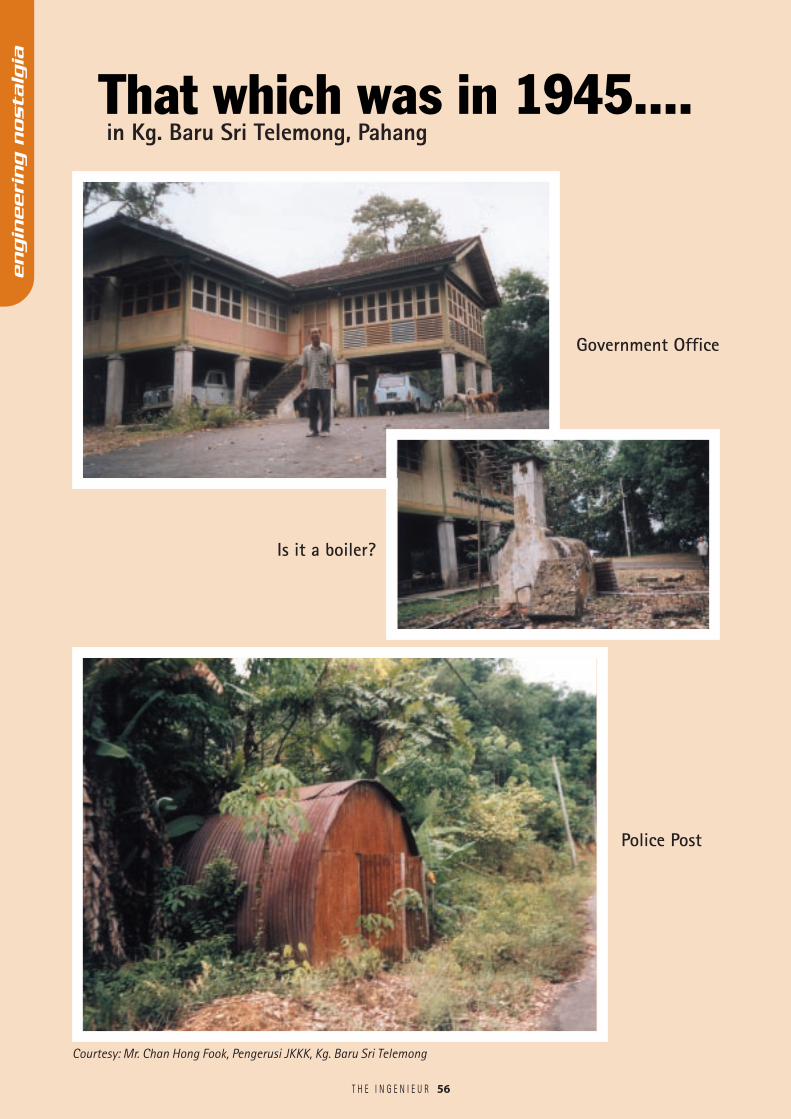
That which was in 1945....
56T H E I N G E N I E U R
Police Post
engin
eeri
ng n
osta
lgia
Is it a boiler?
Government Office
Courtesy: Mr. Chan Hong Fook, Pengerusi JKKK, Kg. Baru Sri Telemong
in Kg. Baru Sri Telemong, Pahang
![INDEX [housewares.blob.core.windows.net] · 1524-EMERALD-GREEN 1524-LIGHT-GREEN 1525-BERBER 1525-BLACK-BROWN 1525-BROWN 1525-BURGUNDY 1525-EMERALD-GREEN 1525-LIGHT-GREEN 1526-BROWN](https://static.fdocuments.us/doc/165x107/5f82d2e19f012e44495be61c/index-1524-emerald-green-1524-light-green-1525-berber-1525-black-brown-1525-brown.jpg)