
Energy Efficiency E-module Guidance 1... · Energy Efficiency E-module Guidance ... The learning...
32
Energy Efficiency E-module Guidance Building Fabric Measures
Transcript of Energy Efficiency E-module Guidance 1... · Energy Efficiency E-module Guidance ... The learning...
Energy Efficiency E-module
Guidance
Building Fabric Measures
Building Fabric Measures | 2
Contents
1 Introduction 4
2 Learning Objectives and Outcomes 4
2.1 Learning Objectives 4
2.2 Learning Outcomes 4
3 Heat Loss through Building Fabric 5
3.1 Thermal envelope 5
3.2 U-values 5
4 Best Practice in the Design and Specification of Retrofit Projects 7
4.1 Asking the Important Questions 7
4.2 Understanding Building Construction 7
4.2.1 Type of Structure 7
4.2.2 Type of Roof Space 8
4.2.3 Windows 8
4.2.4 Condition of the Building 8
4.3 Benchmarking 9
4.4 Selection and Specification of Retrofit Projects 9
4.5 Assessing Other Impacts 10
4.6 Project Management 10
4.7 Monitoring and Analysis 11
5 Identifying Building Fabric Problems 12
5.1 Physical Survey 12
5.2 Survey Checklist 12
5.3 Thermography 13
5.4 Ventilation and Air Pressure Testing 13
6 Improving Building Fabric Performance 14
6.1 Roof and Lofts 14
6.1.1 Pitched Roof with Flat Ceilings and Loft Space 14
6.1.2 Pitched Roof with no Flat Ceiling 14
6.1.3 Flat Roof 14
6.2 Walls 14
6.2.1 Cavity Walls 14
6.2.2 Solid Walls 15
6.2.3 External Wall Insulation 15
6.2.4 Internal Wall Insulation 15

Building Fabric Measures | 3
6.3 Windows 16
6.4 Reducing Solar Gains 17
6.5 Doors 17
6.6 Floors 17
6.6.1 Suspended Timber Ground Floors 17
6.6.2 Solid Ground Floors 18
6.7 Reducing Drafts 18
6.7.1 Openable Windows 18
6.7.2 Regular Maintenance of Doors 18
6.7.3 Sealing Gaps 18
6.8 Adjustment to Heating Controls 19
6.9 Selection of Insulation Materials 19
7 Building the Business Case 20
7.1 Estimating Savings in Energy Use from Improvements to Building Fabric 20
7.1.1 Top Down Estimation 20
7.1.2 Building Modelling 21
7.2 Simple payback period 21
7.3 Discounted Cash Flow 22
8 Further Useful Links and Documents 26
Building Fabric Measures | 4
1 Introduction
This guidance document follows the format of the associated e-module ‘Building Fabric
Measures’ and provides further details on the subjects covered in the e-module.
Please note that module users working in a healthcare environment should always refer to
the relevant Scottish Health Technical Memorandum (SHTM) prior to considering installation
of the measures suggested in the module. The advice given in the SHTM may conflict with
the advice given in this module, as it has been developed for the wider public sector. The
relevant SHTM can be found on the Health Facilities Scotland website.
2 Learning Objectives and Outcomes
2.1 Learning Objectives
The learning objectives for the module are:
Understand the relationship between building fabric and energy use;
Be able to discuss best practice in the design and specification of retrofit projects;
Know how to identify problems with building fabric; and
Be able to compare measures for improving the performance of building fabric.
2.2 Learning Outcomes
The learning outcomes for the module are:
Identify areas of high heat loss within buildings;
Understand the wider incentives for building fabric upgrades;
Discuss the range of factors that need to be considered before starting a building fabric
project;
Undertake a walk around energy survey;
Examine the benefits and limitations of key methods in identifying building fabric
problems;
Discuss specific improvement measures for each of the major building elements; and
Summarise the key aspects of retrofitting improvement measures when building a
business case.
Building Fabric Measures | 5
3 Heat Loss through Building Fabric
3.1 Thermal envelope
The thermal envelope is the collection of building fabric elements which make up the
external thermal barrier of a building.
Buildings lose heat through all parts of their thermal envelope, including the floors, walls,
roofs, windows and doors. Buildings also lose heat through air leakage.
The proportion of heat lost through different thermal elements varies widely from building
to building, and is influenced by factors such as the shape of the building, the thermal
characteristics of the materials used in its existing fabric, and its overall condition.
To illustrate the variability in performance that is dependent upon shape and size - a tall
narrow building will lose the majority of its heat through its walls, whereas a low and wide
building will lose a much larger proportion of heat through its roof.
As another example, some public buildings have a high percentage of their façade made up
of windows. In these cases, the windows can represent a significant source of heat loss as
they conduct heat faster than masonry or other wall construction material. However, in
buildings with much smaller windows, proportionally more heat will be lost through the walls
than the windows.
Because of the wide variation in building characteristics, there is no firm rule for how much
heat is lost through any one part of a building. However, we do know that floors typically
represent the smallest source of heat loss (as heat travels upwards), while walls and roofs
represent the largest as they constitute most of the building’s exposed external envelope.
Whatever the route that heat is lost by, it will be responsible for wasted energy and
correspondingly high space heating bills. Improving the performance of building fabric will
reduce this wastage, helping to drive down costs.
Therefore by improving the thermal performance of building fabric, it is possible to make
long-term, sustained savings on the amount of energy used for space heating.
3.2 U-values
The U-value is the heat transfer co-efficient of a specific material. U-values are measured in
W/m2K, where the K standards for Kelvin1. The U-value for each different construction is
dependent on the layers of fabric that have been used to build it up.
To understand the improvement in U-value associated with a retrofit measure you need to
generate a U-value for the existing building fabric and one for the improved building fabric.
This will enable you to decide if this improvement will generate enough cost saving to justify
the investment in the improvement.
Conductivity is a measure of its inherent ability to facilitate the passage of heat. It is
normally referred to as a ‘k value’. Values for commonly used building materials can be
found in publications such as the New Metric Handbook and the Architects’ Pocket Guide.
Similarly CIBSE provide a basic range of values and manufacturers will generally provide
specific values for their products2.
1 Kelvin is an SI unit for the measurement of temperature. 2 Please refer to www.bre.co.uk/filelibrary/pdf/rpts/br_443_(2006_edition).pdf for further information [accessed 26/08/2014]

Building Fabric Measures | 6
The U-value is defined as being reciprocal of all the resistances of the materials found in the
building element. The resistance of a building material is derived by the following formula:
R = (1/k) x d. Where k is the conductivity of the building material and d is the material
thickness.
The formula for the calculation of a U-value is:
U (for an element of the building i.e. a type of wall, type of floor, type of roof or type of
window) = 1 / (Rso + Rsi + R1 + R2 ...).
Where Rso is the fixed external resistance and Rsi is the fixed internal resistance. Typically,
the internal resistance for a wall is 0.13m2K/W and the external resistance is 0.04 m2K/W
but you should check this for your particular building when you are doing your calculations.
Building Fabric Measures | 7
4 Best Practice in the Design and Specification of Retrofit Projects
4.1 Asking the Important Questions
Before beginning a project to improve building fabric, there are a range of factors to
consider. These include its setting, how it is used and plans for its future.
Important questions to ask include:
Who are the stakeholders for the building? Who are the users and what do they want
from the building?
Are there known issues with the building that relate to its thermal performance and if so
what are they? This can help to prioritise actions.
What is its design life? Are there any known limitations? If there are long-term plans to
replace the building then what is the maximum payback from any improvements that
should be considered?
How is it used? What are its hours of occupation? This will help with any calculations to
assess potential savings.
Are any changes in function expected? Does a department plan to move? If so will the
use and function of the space change and might this impact on any decisions to invest
in building fabric improvements?
Is the building listed or in a conservation area? Is its appearance – internal or external
– significant in any other way?
Each of these factors may influence the selection of improvement measures that are
appropriate for the fabric of the building. They should all be taken into consideration from
the outset of any project.
4.2 Understanding Building Construction
Before considering making fabric improvements it is also necessary to understand how the
building is constructed. This will help to determine what types of measures can be
implemented.
In undertaking these assessments in older buildings, other important factors such as the
presence of asbestos should be considered. This represents both a health and safety issue
and potentially a significant barrier to some forms of improvement work.
4.2.1 Type of Structure
Is the building constructed from solid masonry? This may be brick or stone.
Does it have cavity walls? If so, are they insulated?
Does it have a concrete frame and panel structure?
Is there a timber frame?
Each of these forms of construction will have a slightly different appearance from the
outside of the building, and are generally easy to spot. But the hardest difference to spot is
the difference between solid wall and cavity wall construction. In this instance measuring
the size of the bricks or stones and the width of a wall at an aperture (window or door) can
help to confirm if a cavity is present.
A cavity wall that is yet to be filled offers an easy and relatively low cost measure to
upgrade the thermal performance of a building. On the other hand a solid wall will require a
different and higher cost solution. This usually involves the fitting of internal or external
Building Fabric Measures | 8
insulation directly on to the wall. Therefore knowing the difference between the two
construction types from the outset is essential.
4.2.2 Type of Roof Space
The accessibility and type of roof space is also important to the type of solution that can be
selected. Being able to identify the type of roof structure early on in the process will mean
that the correct solution can be sought.
Does it use panel, steel frame, rafter and purlin or truss construction?
Is there an attic space and is it ventilated? If it does can the space be easily accessed
and is there enough headroom to safely move about in it? The answers to these
questions will dictate if insulation can be fitted and the most appropriate type to use.
Is there any existing insulation at rafter level or at ceiling level? Often existing
insulation is thin, has become compressed, or been displaced, and is therefore no
longer effective.
4.2.3 Windows
Windows are often responsible for a significant proportion of heat loss from a building. As a
result windows are clearly an area for further consideration, starting with an assessment of
the current windows in the building.
What are the frames made of – are they timber, metal or uPVC? – This will give an
indication of their age, and possibly their airtightness.
What type of glazing has been used? If single glazing is used is secondary glazing
present and are curtains, blinds or shutters being used to reduce heat loss. If sealed
double or triple glazing is used are they air or argon filled? The latter gives improved
thermal performance. Have low-emissivity coatings been used? Each of these window
and glazing types have varying thermal performance and U-values. Therefore
identifying them correctly will help determine if an upgrade is possible and if it is how
cost effective it is likely to be.
Have the windows been well maintained? What is the condition of the glazing, the
frames and the seals? Have the windows warped over time leading to reduced air
tightness? Have the double glazing unit seals been compromised, allowing condensation
to form within the panels and reducing their thermal performance?
4.2.4 Condition of the Building
Before considering any investment to improve the fabric of the building it is important to
first assess the overall condition of the building and to identify any areas where there are
failures in the fabric. This is because in many instances these failures are contributing to
heat loss.
First it is important to identify any areas of moisture ingress or damp. This is particularly
important if you are considering any form of wall or roof insulation as moisture may become
trapped within the building and cause long term damage. Pointing on masonry buildings
should be checked, and all rainwater goods (gutters, downpipes and drains) must be
functioning correctly.
It is also necessary to consider the air tightness of the building and to identify what could be
achieved at low cost by reducing uncontrolled ventilation. This may apply to areas such as
service penetrations, window and door seals and any lobbies present. Occupant behaviour
can be an issue here making the identification of the lack of closers on eternal doors part of
this assessment.
Building Fabric Measures | 9
At this stage its worth consulting with building users to understand whether there are issues
in particular areas of the building, such as over or under-heating, or draughts. This can help
to prioritise subsequent actions.
4.3 Benchmarking
Benchmarking is a method for comparing how much energy a given building uses with
buildings that have a similar form and/or function. This is normally expressed in terms of
the energy used per square metre of heated space over a given time period – usually a year
– so the term would be kWh/m2pa. Benchmarks are normally compared using data
published by the Chartered Institution of Building Services Engineers (CIBSE) or the Carbon
Trust.
If the energy use for space heating is relatively high in comparison to buildings of similar
age, condition and function, this may indicate that the space heating system is poorly
performing or that the building fabric has potential for improvement.
4.4 Selection and Specification of Retrofit Projects
The work described in the previous sections will have allowed you to have identified target
areas for further consideration based on the construction of your building, its current
condition and known occupant concerns.
Once you have identified a list of options then you need to work out how to evaluate them
and determine which is the most effective. If you are considering making building fabric
upgrades, you should work with the building stakeholders that you have identified to
determine the criteria you will use to evaluate retrofit options. This is because in addition to
cost considerations different options come with different associated benefits and some
stakeholders may value these differently. Other issues to consider are the impacts of any
improvement works on the operation on the building and its occupants while the work is
being carried out.
As a result, key issues to consider will include:
Total cost;
Cost-effectiveness, including payback;
Impact on building users (both during and after the project);
If the intervention will need planning permission or comes under building control and if
so the impact of this on the project and the implementation timeline.
Changes to embodied energy and/or carbon;
The level of reductions in CO2 emissions from buildings in use;
What waste will be generated and how will this be managed;
Impact on the local community (including visual impacts, heritage value, etc.);
Scarcity of the materials to be used for retrofit; and
Other objectives that could be effectively achieved at the same time as fabric retrofit
such as:
- Prevention of overheating/improved comfort;
- Draught reduction;
- Reduction in noise pollution;
- Less water use;
- Improvements in appearance; and
Building Fabric Measures | 10
- Reductions in maintenance costs.
These additional benefits need to be valued and taken into account at the same time as the
potential gains from reduced heat losses are estimated.
4.5 Assessing Other Impacts
Thermal upgrade has implications for many aspects of a building’s structure and services.
Of these, internal or external wall insulation will probably have the greatest an impact on
the building and its appearance. External wall insulation may require extension to the roof
line, window sills will need to be extended, and any exterior services such as rainwater
drainage will all be affected. Internal wall insulation will require alterations to power and
lighting, radiators will need to be refitted, and architraves, window sills and skirting boards
may all need to be changed.
It is important to look at any building holistically. Just as a building is physically connected
to all of its parts, any measures to improve one thermal element will have an impact on the
performance of other elements, and potentially on services as well. For example, reducing
uncontrolled ventilation, whether by draught proofing, window replacement or wall
insulation, will have an impact on indoor air quality. Leaky buildings are at least well
ventilated, so it is necessary to check whether air changes per hour are in danger of falling
below the minimum standards set out in Section 3 of the Non-Domestic Technical
Handbook3.
Lastly, reducing heat losses will of course reduce the demand for heat. This may mean that
the existing space heating generation and distribution system is oversized, or that additional
controls need to be introduced. This might include zoning of distribution systems or more
local controls such as TRVs on radiators. This aspect of thermal upgrade is essential to avoid
any overheating but also to ensure that predicted savings are achieved in reality.
Depending on the nature of your project, it may be appropriate to use an environmental
impact assessment tool such as BREEAM or SKA Rating. This could help you to build select
wider environmental criteria into your tendering process further down the line. Both options
will provide a wide environmental assessment perspective. A BREEAM assessment uses
recognised measures of performance, which are set against established benchmarks, to
evaluate a building’s specification, design, construction and use. The areas used in a
BREEAM assessment cover aspects related to energy and water use, the internal
environment (health and well-being), pollution, transport, materials, waste, ecology and
management processes4 The SKA Rating can be used to assess a refurbishment against
more than a hundred 'good practice' measures covering energy and CO2 emissions, waste,
water, materials, pollution, wellbeing and transport5.
4.6 Project Management
Project management planning is essential for a successful project. It should start well
before the design and specification stage. Key elements to cover are:
Establishing clear responsibility for the project, and responsibility for delivering the
identified cost, carbon and other sustainability elements;
3 The complete set of Non-Domestic Technical Handbooks can be found here
http://www.scotland.gov.uk/Topics/Built-Environment/Building/Building-standards/publications/pubtech 4 Please visit www.breeam.org for further information [accessed 26/08/2014] 5 Please visit www.rics.org/uk/knowledge/more-services/professional-services/ska-rating- for further information [accessed 26/08/2014]
Building Fabric Measures | 11
Ensuring compliance where required with planning regulations, building control, waste
management, health and safety, etc.;
Day to day management of subcontractors and ensuring that the work is undertaken to
an appropriate standard;
Ensuring that any necessary repairs are identified and carried out prior to fabric
improvements;
Providing a point of contact with building occupants during the work and providing
forewarning of potentially disruptive activities such as periods of restricted access, high
noise levels, etc.
Providing the necessary links to any associated works – for example to ensure that
changes required to heating and ventilation systems are implemented as required; and
Project handover – on completion of the project, all relevant information needs to be
made accessible, and users and managers of the building should be trained if necessary
in the operation and performance of the retrofitted building.
4.7 Monitoring and Analysis
A key element to the success of any project is to demonstrate the value that the measure
has brought. Has it delivered the savings that it was expected to and has occupant comfort
improved?
Therefore, wherever possible, monitoring and analysis of information related to the
proposed project should be facilitated at the design stage.
At the planning stage you will need to:
Collect baseline data on all the indicators selected to be used as the criteria for retrofit
decisions.
During and after project implementation you should:
Analyse energy performance results, comparing them with the energy data gathering at
the pre retrofit stage; and
Share your results – both positive and negative – with those in your building and those
responsible for similar public buildings.

Building Fabric Measures | 12
5 Identifying Building Fabric Problems
5.1 Physical Survey
Undertaking a physical survey of your building enables you to confirm all the details of a
building’s construction and its condition. These details are necessary to work out which
retrofit measures could be considered to improve the thermal performance of the building’s
fabric. At the same time, a physical survey will help to identify any defects that should be
remedied prior to carrying out retrofit work.
Prior to carrying out the survey you may wish to access drawings and maintenance records
or other paperwork, as they will often contain information on suitable access points.
A physical survey can take time and you are likely to need access to most areas of a
building. It may also be useful to carry the following equipment:
Camera (you may need to get permission to take pictures in certain areas);
Torch;
Temperature sensor;
Tape measure.
In some buildings, a physical survey will require gaining access to roof space or subfloor
areas, so all relevant Health and Safety procedures should be followed.
5.2 Survey Checklist
Figure 5.1 – Building Fabric Site Survey Checklist
Fabric Element (Circle as needed) Retrofit potential ()
Walls
Cavity – insulated or uninsulated?
Solid – insulation already added or not?
Roof
Insulation at flat ceiling height – depth?
Insulation at sloping rafter level – material and depth?
Floor
Solid – insulation below?
Suspended – insulation built in or no insulation
Doors
Type (side hung, sliding, revolving, roller)
Closure mechanism if hinged or roller (automated or not)
Draught lobbies present?
Windows
Frame type (Timber, steel, upvc)
Glazing type (Single, double, triple, low-e coatings)
Condition of seals (Good / Poor)
Air tightness
Wall/Floor junctions – draughts present / no draughts
Services penetrations – draughts present / no draughts
Check with building occupants
In older buildings the survey should also be used to look out for other problems such as the
presence of asbestos. This is not only a significant health and safety issue, it may also
prevent certain actions being undertaken where it has been decided that the best option is
to leave any asbestos in situ and undisturbed.
Building Fabric Measures | 13
Most buildings are not homogenous. They may have been upgraded in part at different
times or extensions may have been added. In this case a survey template will need to be
completed for each section of the building (in terms of construction date and type) to take
into account these variations.
5.3 Thermography
Another method to investigate the thermal performance of a building is thermal imaging, or
thermography. This uses a thermal imaging camera to generate a picture showing the heat
losses from the external surfaces of a building.
Areas of high heat loss can then be identified, and the causes investigated. Causes vary and
can include:
Poor thermal fabric - such as single glazed windows and thin doors, or uninsulated
roofs;
Air leakage (especially around doors and windows);
Thermal bridging (a thermal bridge, also called a cold bridge, is where a penetration of
the insulation layer by a highly conductive or non-insulating material takes place);
Damp.
Once the cause of the heat loss is identified, the area can be prioritised for improvement.
Many remedies such as reducing air leakage around doors and windows can be low cost and
easy to install.
Thermographic surveys can also be used to compare the performance of a building before
and after refurbishment, or to check the effectiveness of cavity wall or other existing
insulation to identify any weak areas.
Surveys and their interpretation are normally carried out by a trained expert. Surveys can
only be carried out at night when there is the greatest heat differential between the building
and the outside. This enables the differentiation between good and bad performing areas to
be seen most easily. Surveys cannot be undertaken when it is raining as this distorts heat
patterns. This means that typically thermographic services are best carried out on a dry
evening during heating season.
If budget permits, aerial thermography can be very useful on large estates, as it will show
large areas in one image. This can be useful where whole roof structures in larger buildings
are being assessed.
Whatever the type of survey, a report should contain a complete record of the survey, the
equipment used, the environmental conditions, the results and their interpretation. In some
cases a video of the survey with a commentary may also be provided.
5.4 Ventilation and Air Pressure Testing
As discussed in Section 4, achieving good air tightness is a major contributor to good
building thermal performance. The method of assessing the effectiveness of the thermal
envelope is to carry out an air pressure test. This is where the building is sealed up and
pressurised to test for its air tightness or infiltration rate. This can be done on a whole or
part building basis. It should be repeated as measures are introduced to improve air
tightness such as installing improved door and window seals to identify their effectiveness
and to identify if other issues are contributing to leakage.
Building Fabric Measures | 14
6 Improving Building Fabric Performance
6.1 Roof and Lofts
6.1.1 Pitched Roof with Flat Ceilings and Loft Space
Where there is a loft space above a ceiling, it is relatively simple to insulate. Mineral wool is
normally used for this job as it is inexpensive, easy to install and offers relatively short
paybacks.
If the building has this structure, examine the amount of insulation currently in the lost
space. If there is less than 150mm of insulation at present, it is worth adding more – the
current recommended level is 275mm. If you laying a second layer it is advised that you lay
it in the opposite direction (i.e. across the original) as it will cover any gaps in the
insulation.
When adding insulation to loft spaces, always ensure that adequate ventilation is
maintained at the eaves, and insulate water services and ducting to avoid condensation and
freezing pipes.
6.1.2 Pitched Roof with no Flat Ceiling
In this circumstance it is normal for an occupied room to extend right into the roof space
and that some kind of boarding is attached to the roof structure to provide a decorative
finish. Here, it is difficult to know if the roof structure is already insulated.
If drawings are not available, it may be necessary to open up a section of the roof to
establish the level of insulation. Thermography can also be used to assess the level of heat
loss.
Modern buildings will have been constructed with insulation built into the structure and
usually there is little to be gained from adding more insulation, unless the building was
constructed at the earliest stages of the requirement to insulate. If the existing insulation is
inadequate, more can be added above, between, or below the rafters, depending on access
and available head room. Where rafters require cross-ventilation this must be maintained.
Due to the level of disruption involved, insulation is normally only added above the rafters
when a roof is being replaced for some other reason such as major refurbishment of the
occupied space.
6.1.3 Flat Roof
Flat roofs can be insulated above, below, or within, the rafter matrix. Like pitched roofs,
insulation is normally only added on top of the rafters when the roof covering is replaced.
This happens more frequently with flat roofs than for pitched roofs due to the fragility of
roofing felt, so this presents a good opportunity to improve the thermal performance of this
building element. Insulation can be added internally at any time but you will need to allow
for the reduction in head height and for adaptation of elements contained within the ceiling
such as lighting.
6.2 Walls
6.2.1 Cavity Walls
Cavity wall insulation is common in the domestic sector but many non-domestic buildings of
the same period could also benefit from this procedure. Installing cavity wall insulation is a
relatively simple process. Small holes are drilled from the outside of the building to give
access to the cavity and insulation is piped in before the holes are refilled. As installation
Building Fabric Measures | 15
work is undertaken from the outside of the building it causes minimal disruption other than
drilling noise. This makes it suitable to carry out at any time.
As with any kind of wall insulation, the condition of the wall should be checked thoroughly
and any necessary repairs completed before commencing. Due to the materials available
and the size of most cavities, this type of insulation will not bring the U-value of a wall down
to modern thermal standards, but it will still make a significant improvement at relatively
little cost.
6.2.2 Solid Walls
Solid walls can be insulated either externally or internally. In each case there are technical
risks that need to be addressed and, if the building is old, there may be a significant
heritage consideration.
A decision needs to be taken at an early stage as to whether the insulation system selected
will be vapour-open or vapour-closed. This relates to the breathability of the insulation and
is important as it influences the risk of moisture build-up. This distinction and the risks of
condensation are not fully understood by all architects; equally, insulation system
manufacturers and installers may not be the best sources of impartial advice. For this
reason it is important to get independent specialist advice on moisture risks when
considering the application of either internal or external wall insulation.
The next two sections describe the options for solid wall insulation in more detail.
6.2.3 External Wall Insulation
External wall insulation (EWI) is added to the external face of a wall and then covered in a
new weather-proof layer to protect it. EWI has the advantage that the original masonry wall
held within the new insulated shell becomes “thermal mass”. This thermal mass is able to
store heat from internal heat gains and dissipate it slowly, with the result that the building
does not react as much to changes in external temperature. This helps prevent overheating
as there is sufficient mass to store heat gains in summer, releasing them more slowly at
night as the building cools.
There are several key concerns that must be addressed when considering EWI. These are:
Where the appearance of the building is important this option cannot be considered
unless the building is already rendered and the effect can be reproduced without
creating detailing and aesthetic issues at eaves, gables, window reveals and doorways;
Whether the eaves need to be extended;
Thermal bridging at eaves and reveals;
Impact on external space; and
Impact on services (e.g. water, electricity, communications systems) on the outer skin
plus drainage runs.
Insulation systems should avoid the use of sealants other than at joints with windows.
Sealants break down over time and this can cause the EWI to trap moisture, leading to
serious damp issues. Exposed locations are particularly vulnerable and detailing in these
areas needs to be done carefully to minimise risk.
EWI will also reduce natural ventilation. It is therefore important to ensure that adequate
ventilation is provided post retrofit.
6.2.4 Internal Wall Insulation
Internal wall insulation (IWI) is fixed to the inner face of the external walls and a new
finishing layer (usually plasterboard) is then added on top. All joinery and services must
Building Fabric Measures | 16
first be removed and then reinstated, which adds considerably to the cost of the job. As the
process is disruptive, occupants normally have to move out of the affected rooms, and
sometimes the entire building needs to be cleared. For this reason, IWI is normally only
carried out during major refurbishment projects.
IWI has the disadvantage that space is lost from the interior of the building (usually about
100mm on external walls) and that the masonry walls are then outside the thermal
envelope. This means that they do not contribute to the thermal mass meaning that heat is
not stored as effectively as with EWI. The technical risks are also much greater. Any
moisture which enters the wall will not be able to evaporate internally if a sealed system is
used. IWI also has the effect of cooling the masonry as heat passes from the inner face to
the outer face at a much slower rate, so any moisture which enters the wall is less likely to
evaporate externally.
Lastly, as internal partition walls and other essential features, such as staircases, are often
abutting the external walls, it is usually impossible to install a continuous layer of IWI. This
leads in turn to thermal bridging and condensation with associated mould growth and risks
to human health.
6.3 Windows
More heat is usually lost through badly fitting windows than through the glazing itself. The
first place to start when looking at energy saving from windows is to draught proof and seal
wherever possible.
Single glazed windows are generally inefficient in thermal terms. There are four options
when considering how to reduce this heat loss from single glazed windows. In ascending
order of cost, these are:
Using curtains, blinds and shutters;
Installing secondary glazing;
Glazing replacement; and
Window replacement.
Curtains, blinds and shutters are surprisingly effective at reducing heat loss. Research by
English Heritage indicates that the U-value of a single glazed window can be halved with the
addition of any of these, so this can do much of the work of more costly interventions.
Secondary glazing is also very effective at reducing heat losses, and is a useful technique
where the appearance of the building needs to be maintained. In this case it is important to
ensure that any glazing bars in the secondary glazing align with the original window so as
not to create a visual distortion. Secondary glazing also needs to be easily removable for
access and cleaning.
Glazing replacement can be used where the original glass is not of historic value. Timber
frames can be adapted to receive a thicker double-glazed panel, retaining the window
frames themselves. This not only reduces cost and visual impact but also environmental
impact and damage to the masonry, as the frames are not being replaced.
Window replacement is the last and most expensive option when considering window
upgrades. Sadly it is often the first option offered by installers as there is more profit in a
more expensive job, even if there is little or nothing wrong with the underlying frames.
Where double glazing is already present, there is usually no point in upgrading this to the
latest thermal standards. However, early double glazing had a very thin (4mm) gap
between the panes of glass and in many cases the seals have failed and there is
Building Fabric Measures | 17
condensation forming within units. Under these circumstances replacement of the glazing
unit should be considered.
6.4 Reducing Solar Gains
Solar gains through windows can be a cause of overheating in buildings. Solar-control film
can be applied to existing glazing. This can also reduce daylight levels and affect the colour
rendering of the remaining daylight so there is a trade-off to be considered here.
Another option is external fixed solar shading, which reduces unwanted heat and light from
the sun during the summer, and can allow low-angled winter sun to provide some passive
heating. Although the heat from the sun is most intense on south facing facades, solar gain
can be just as problematic on east or west facing facades which are susceptible to
overheating, especially at the beginning or end of the day.
A longer-term solution to excessive solar gains in low level buildings is tree planting near to
southern elevations. If the trees are deciduous then light and heat will still be able to
penetrate the building during winter months. Trees take time to mature so it is likely that
other solutions will be required while they grow to sufficient height.
6.5 Doors
Doors also present a number of opportunities to reduce heat loss from buildings. Many
door-related solutions are mainly applicable when carrying out major refurbishment
projects, but there are also low-cost opportunities that can be implemented immediately.
For example, fitting self-closers ensures that all external doors are kept closed when
heating or cooling systems are in operation. Self-closers are a relatively inexpensive
measure which can often be installed by on-site maintenance staff. It may also be relevant
to consider fitting automatic closers to external doors and to internal doors that separate
areas with different heating or cooling requirements.
All doors should be effectively draught proofed (see Section 6.7 below on Draught Proofing).
Installing a draught lobby at a frequently used entrance is another way to reduce draughts.
Lobbies should be large enough to provide unrestricted access, and to enable one set of
doors to be closed before the other is opened. Where possible, the two sets of doors should
have automatic control. Where space does not allow a draught lobby to be constructed, a
revolving door could be considered.
Roller shutter doors can be a substantial source of heat loss in service areas. To reduce this
problem, they can be motorised and then controlled automatically by PIR sensors or
manually switched (or remote controlled). This will allow the rapid closure of the doors,
which minimises heat loss.
6.6 Floors
6.6.1 Suspended Timber Ground Floors
Where there is access to the underside of suspended floors, insulation can be added. Where
there is no access, insulating between the joists can only be carried out from above. To do
this, the flooring must be lifted so it is usually only worthwhile if floor renovation is part of a
planned refurbishment. When installing insulation, you should:
Maintain ventilation in the subfloor space;
Seal any gaps at the wall/floor junction (normally at the base of the skirting boards);
If using expanded polystyrene insulation, ensure that electrical cables do not come into
direct contact with the insulation; and
Building Fabric Measures | 18
Insulate any heating pipes which are located below the insulation.
6.6.2 Solid Ground Floors
Opportunities for insulating existing solid ground floors are limited; the possibility of adding
insulation only occurs where an existing floor finish (such as old, wood block flooring or a
cracking screed) needs replacing.
Solid ground floors can be insulated to reduce heat loss by:
Digging up the floor and adding insulation within the new construction back to the
original level. This is an expensive and disruptive job; and
Installing insulation above the existing floor slab and installing a final wearing surface
above the insulation.
Adding insulation on top of an existing slab raises the finished floor level so causes issues at
doorways and staircases and is therefore an expensive and disruptive exercise. As heat
losses through solid ground floors are the least of all thermal elements, a thin insulating
layer (carpet or thermal underlay to a hard surface) is normally the most cost-effective
option.
6.7 Reducing Drafts
Draughts play a major role in reducing the thermal efficiency of a building.
Air enters and leaves a building by both controlled ventilation, through windows and
dedicated air vents, and uncontrolled ventilation, such as poorly fitted windows or doors.
The uncontrolled ventilation of a building is often called air infiltration, indicating that the air
has worked its way into the building rather than being brought in for ventilation. Air
infiltration is not controlled and rarely ventilates the building in the required manner. A
‘leaky’ building with poor airtightness will allow cold draughts to enter and heat to escape
through cracks and gaps in the building fabric, reducing staff comfort in the process.
Several key areas can reduce draughts in your building.
6.7.1 Openable Windows
Openable windows can be draught-stripped to reduce heat loss. In naturally ventilated
areas, controllable trickle ventilators can be fitted to ensure that minimum quantities of
fresh air can be provided after draught-stripping. It is important ensure that good quality
materials are specified and correctly fitted. You may also wish to consider permanently
sealing unused opening windows to reduce draughts still further.
6.7.2 Regular Maintenance of Doors
Timber doors move slightly through the seasons with thermal expansion and contraction.
Therefore it is important to keep this under review to ensure that doors and locks continue
to operate correctly and that draught proofing remains effective. Regularly check all seals
and draught stripping for signs of damage and replace them if required.
6.7.3 Sealing Gaps
Sealing any gaps at junctions between thermal elements can improve comfort and reduce
energy costs. The most common areas for gaps to occur are at junctions between walls and
windows, and walls and doors.
Building Fabric Measures | 19
6.8 Adjustment to Heating Controls
Following building fabric upgrades and refurbishment, maximum energy savings will only be
achieved if the heating system and its controls are adjusted to take advantage of the lower
rate of heat loss. Boilers and heat emitters may need resizing. System controls must
checked to ensure that they are responsive to varying conditions throughout the building,
and able to switch heating on or off in each zone as required to stay between the set points.
6.9 Selection of Insulation Materials
The selection of insulation for roofs, walls or floors is a complex exercise. The materials
most commonly used are mineral wool (for loft spaces and some walls) and polystyrene,
phenolic or polyisocyanurate foam (for pitched roofs, walls and floors). These materials are
derived from non-renewable resources, mainly from oil. Some insulation material is
produced from recycled glass.
There are plenty of alternative materials available to use as insulation which are derived
from natural or renewable sources, such as waste wood or hemp. For wall insulation in
particular, a decision also needs to be made as to whether the insulation system is vapour
open or vapour closed. Most foams are closed cell structures and do not allow moisture to
pass through, running the risk of moisture being trapped in the structure. Independent
expert advice is therefore essential at the project specification stage.
It is also worthwhile considering the embodied carbon (carbon involved in the
manufacturing of the material) or recycled content of material choices6.
6 Please refer to www.resourceefficientscotland.com/construction for more information for further information [accessed 26/08/2014]
Building Fabric Measures | 20
7 Building the Business Case
Building a compelling business case is the key to securing funding for building fabric
upgrade projects. Each public sector organisation will have their way of developing a
business case and gaining approval for it.
Energy or environmental managers, facilities managers and works engineers often find it
hard to obtain funding for projects to improve the thermal performance of buildings. This is
because their projects are typically not seen as core to the operation of the public sector
organisation. They are also not mandatory from a legal or regulatory perspective. That said
within regulatory schemes such as the Carbon Reduction Commitment Energy Efficiency
Scheme (CRC), there is a financial benefit from implementing projects leading to lower
energy use.
In many cases upgrades to building fabric may be smaller scale than other projects being
dealt with by decision makers, diminishing their perceived importance. Furthermore, these
projects can be technical and therefore outside the experience of the decision-makers,
which increases the perceived level of risk associated with them.
It is important to know what information to present in your business case. Decision makers,
will generally be interested in cost reductions but in the public sector often a much wider
range of sustainability criteria need to be taken into account as well (see Section 4.4). The
project for which you are presenting a business case must therefore offer a compelling
financial return and also present all other relevant benefits that are important to your
organisation.
It is important to ensure that the business case clearly takes account of all of these factors
and presents them in a clear and concise way. In this section we will look at the specific
information that you will need to prepare to develop the financial case, and explain how to
put it together.
7.1 Estimating Savings in Energy Use from Improvements to Building Fabric
There are two ways in which the savings from improvements to building fabric can be
estimated. These are top down estimation or building modelling.
7.1.1 Top Down Estimation
Firstly it is necessary to work out the amount of energy being currently used for space
heating. If the building is heated by gas, this is a simple matter of estimating the amount of
energy used by any other services heated by gas and deducting these. Examples of
alternative uses are cooking and water heating.
Secondly, the heat losses through the different elements of the building fabric need to be
estimated. As explained earlier, this is very dependent on the shape of the building, the
proportion of the external envelope taken up by windows, and on the U-values of the
existing building elements. This means that an experienced assessor is needed to make this
judgement. Figure 7.1 estimates the breakdown of heat losses for a notional building.
Building Fabric Measures | 21
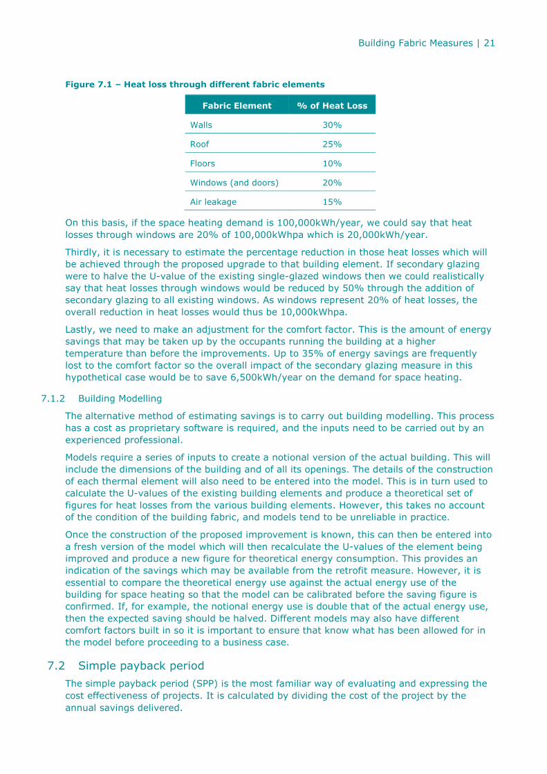
Figure 7.1 – Heat loss through different fabric elements
Fabric Element % of Heat Loss
Walls 30%
Roof 25%
Floors 10%
Windows (and doors) 20%
Air leakage 15%
On this basis, if the space heating demand is 100,000kWh/year, we could say that heat
losses through windows are 20% of 100,000kWhpa which is 20,000kWh/year.
Thirdly, it is necessary to estimate the percentage reduction in those heat losses which will
be achieved through the proposed upgrade to that building element. If secondary glazing
were to halve the U-value of the existing single-glazed windows then we could realistically
say that heat losses through windows would be reduced by 50% through the addition of
secondary glazing to all existing windows. As windows represent 20% of heat losses, the
overall reduction in heat losses would thus be 10,000kWhpa.
Lastly, we need to make an adjustment for the comfort factor. This is the amount of energy
savings that may be taken up by the occupants running the building at a higher
temperature than before the improvements. Up to 35% of energy savings are frequently
lost to the comfort factor so the overall impact of the secondary glazing measure in this
hypothetical case would be to save 6,500kWh/year on the demand for space heating.
7.1.2 Building Modelling
The alternative method of estimating savings is to carry out building modelling. This process
has a cost as proprietary software is required, and the inputs need to be carried out by an
experienced professional.
Models require a series of inputs to create a notional version of the actual building. This will
include the dimensions of the building and of all its openings. The details of the construction
of each thermal element will also need to be entered into the model. This is in turn used to
calculate the U-values of the existing building elements and produce a theoretical set of
figures for heat losses from the various building elements. However, this takes no account
of the condition of the building fabric, and models tend to be unreliable in practice.
Once the construction of the proposed improvement is known, this can then be entered into
a fresh version of the model which will then recalculate the U-values of the element being
improved and produce a new figure for theoretical energy consumption. This provides an
indication of the savings which may be available from the retrofit measure. However, it is
essential to compare the theoretical energy use against the actual energy use of the
building for space heating so that the model can be calibrated before the saving figure is
confirmed. If, for example, the notional energy use is double that of the actual energy use,
then the expected saving should be halved. Different models may also have different
comfort factors built in so it is important to ensure that know what has been allowed for in
the model before proceeding to a business case.
7.2 Simple payback period
The simple payback period (SPP) is the most familiar way of evaluating and expressing the
cost effectiveness of projects. It is calculated by dividing the cost of the project by the
annual savings delivered.
Building Fabric Measures | 22
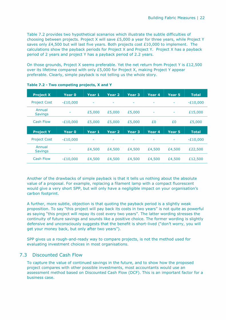
Table 7.2 provides two hypothetical scenarios which illustrate the subtle difficulties of
choosing between projects. Project X will save £5,000 a year for three years, while Project Y
saves only £4,500 but will last five years. Both projects cost £10,000 to implement. The
calculations show the payback periods for Project X and Project Y. Project X has a payback
period of 2 years and project Y has a payback period of 2.2 years.
On those grounds, Project X seems preferable. Yet the net return from Project Y is £12,500
over its lifetime compared with only £5,000 for Project X, making Project Y appear
preferable. Clearly, simple payback is not telling us the whole story.
Table 7.2 - Two competing projects, X and Y
Project X Year 0 Year 1 Year 2 Year 3 Year 4 Year 5 Total
Project Cost -£10,000 - - - - - -£10,000
Annual Savings
- £5,000 £5,000 £5,000 - - £15,000
Cash Flow -£10,000 £5,000 £5,000 £5,000 £0 £0 £5,000
Project Y Year 0 Year 1 Year 2 Year 3 Year 4 Year 5 Total
Project Cost -£10,000 - - - - - -£10,000
Annual
Savings - £4,500 £4,500 £4,500 £4,500 £4,500 £22,500
Cash Flow -£10,000 £4,500 £4,500 £4,500 £4,500 £4,500 £12,500
Another of the drawbacks of simple payback is that it tells us nothing about the absolute
value of a proposal. For example, replacing a filament lamp with a compact fluorescent
would give a very short SPP, but will only have a negligible impact on your organisation’s
carbon footprint.
A further, more subtle, objection is that quoting the payback period is a slightly weak
proposition. To say “this project will pay back its costs in two years” is not quite as powerful
as saying “this project will repay its cost every two years”. The latter wording stresses the
continuity of future savings and sounds like a positive choice. The former wording is slightly
defensive and unconsciously suggests that the benefit is short-lived (“don’t worry, you will
get your money back, but only after two years”).
SPP gives us a rough-and-ready way to compare projects, is not the method used for
evaluating investment choices in most organisations.
7.3 Discounted Cash Flow
To capture the value of continued savings in the future, and to show how the proposed
project compares with other possible investments, most accountants would use an
assessment method based on Discounted Cash Flow (DCF). This is an important factor for a
business case.

Building Fabric Measures | 23
In DCF calculations, all the project’s current and future costs and savings are aggregated
into a single lifetime figure, but with due allowance made for the fact that cash flows in the
far future have less weight than those in the near future.
Table 7.3 shows the present value of £1,000 in five years’ time, at various discount rates.
You can compare the present values of a certain cash sum paid at different points in the
future but at a particular discount rate.
Building Fabric Measures | 24
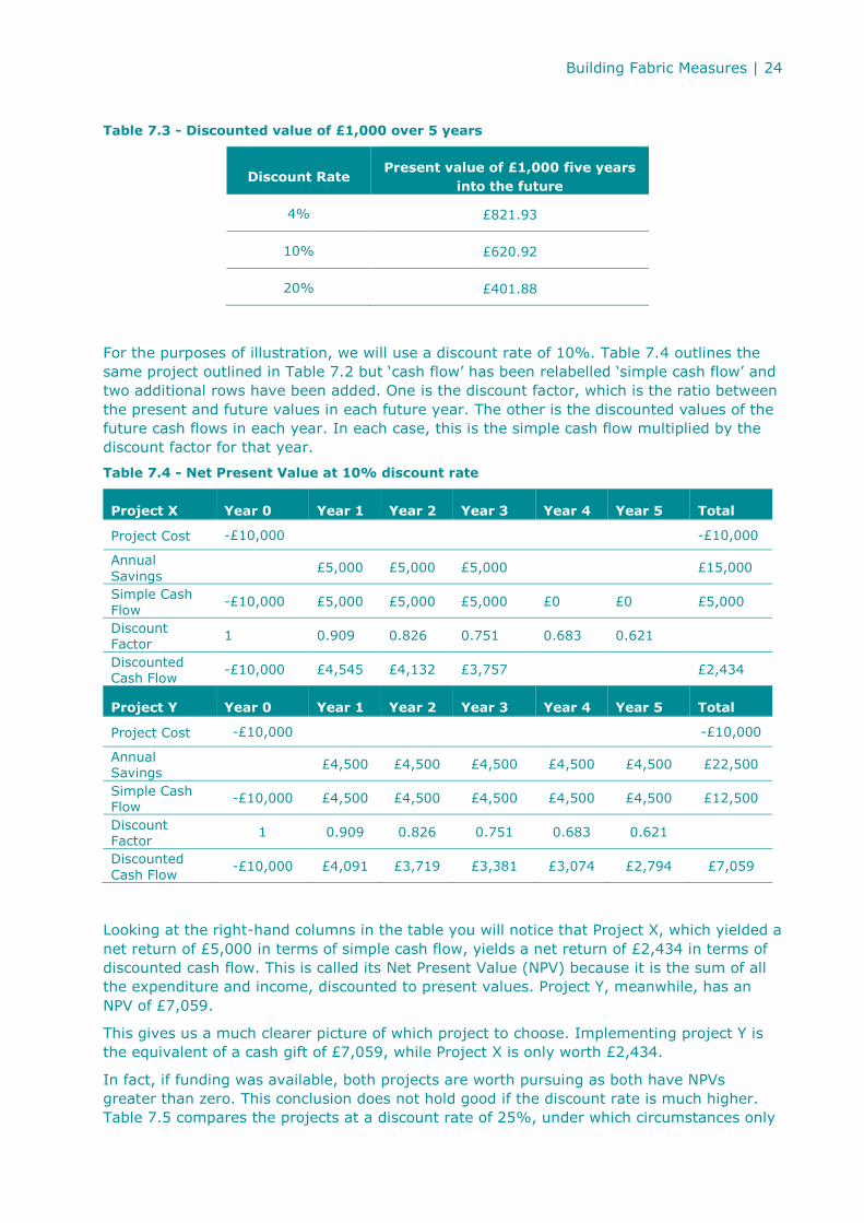
Table 7.3 - Discounted value of £1,000 over 5 years
Discount Rate Present value of £1,000 five years
into the future
4% £821.93
10% £620.92
20% £401.88
For the purposes of illustration, we will use a discount rate of 10%. Table 7.4 outlines the
same project outlined in Table 7.2 but ‘cash flow’ has been relabelled ‘simple cash flow’ and
two additional rows have been added. One is the discount factor, which is the ratio between
the present and future values in each future year. The other is the discounted values of the
future cash flows in each year. In each case, this is the simple cash flow multiplied by the
discount factor for that year.
Table 7.4 - Net Present Value at 10% discount rate
Project X Year 0 Year 1 Year 2 Year 3 Year 4 Year 5 Total
Project Cost -£10,000 -£10,000
Annual
Savings £5,000 £5,000 £5,000 £15,000
Simple Cash
Flow -£10,000 £5,000 £5,000 £5,000 £0 £0 £5,000
Discount Factor
1 0.909 0.826 0.751 0.683 0.621
Discounted Cash Flow
-£10,000 £4,545 £4,132 £3,757 £2,434
Project Y Year 0 Year 1 Year 2 Year 3 Year 4 Year 5 Total
Project Cost -£10,000 -£10,000
Annual Savings
£4,500 £4,500 £4,500 £4,500 £4,500 £22,500
Simple Cash Flow
-£10,000 £4,500 £4,500 £4,500 £4,500 £4,500 £12,500
Discount
Factor 1 0.909 0.826 0.751 0.683 0.621
Discounted
Cash Flow -£10,000 £4,091 £3,719 £3,381 £3,074 £2,794 £7,059
Looking at the right-hand columns in the table you will notice that Project X, which yielded a
net return of £5,000 in terms of simple cash flow, yields a net return of £2,434 in terms of
discounted cash flow. This is called its Net Present Value (NPV) because it is the sum of all
the expenditure and income, discounted to present values. Project Y, meanwhile, has an
NPV of £7,059.
This gives us a much clearer picture of which project to choose. Implementing project Y is
the equivalent of a cash gift of £7,059, while Project X is only worth £2,434.
In fact, if funding was available, both projects are worth pursuing as both have NPVs
greater than zero. This conclusion does not hold good if the discount rate is much higher.
Table 7.5 compares the projects at a discount rate of 25%, under which circumstances only
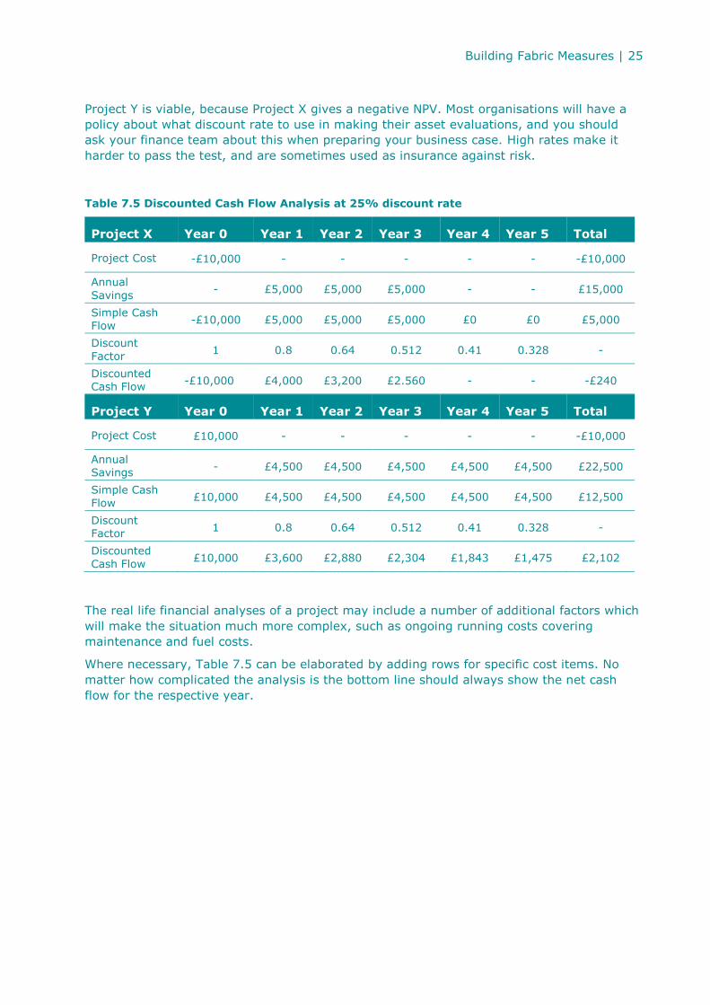
Building Fabric Measures | 25
Project Y is viable, because Project X gives a negative NPV. Most organisations will have a
policy about what discount rate to use in making their asset evaluations, and you should
ask your finance team about this when preparing your business case. High rates make it
harder to pass the test, and are sometimes used as insurance against risk.
Table 7.5 Discounted Cash Flow Analysis at 25% discount rate
Project X Year 0 Year 1 Year 2 Year 3 Year 4 Year 5 Total
Project Cost -£10,000 - - - - - -£10,000
Annual
Savings - £5,000 £5,000 £5,000 - - £15,000
Simple Cash Flow
-£10,000 £5,000 £5,000 £5,000 £0 £0 £5,000
Discount
Factor 1 0.8 0.64 0.512 0.41 0.328 -
Discounted Cash Flow
-£10,000 £4,000 £3,200 £2.560 - - -£240
Project Y Year 0 Year 1 Year 2 Year 3 Year 4 Year 5 Total
Project Cost £10,000 - - - - - -£10,000
Annual Savings
- £4,500 £4,500 £4,500 £4,500 £4,500 £22,500
Simple Cash
Flow £10,000 £4,500 £4,500 £4,500 £4,500 £4,500 £12,500
Discount Factor
1 0.8 0.64 0.512 0.41 0.328 -
Discounted
Cash Flow £10,000 £3,600 £2,880 £2,304 £1,843 £1,475 £2,102
The real life financial analyses of a project may include a number of additional factors which
will make the situation much more complex, such as ongoing running costs covering
maintenance and fuel costs.
Where necessary, Table 7.5 can be elaborated by adding rows for specific cost items. No
matter how complicated the analysis is the bottom line should always show the net cash
flow for the respective year.
Building Fabric Measures | 26
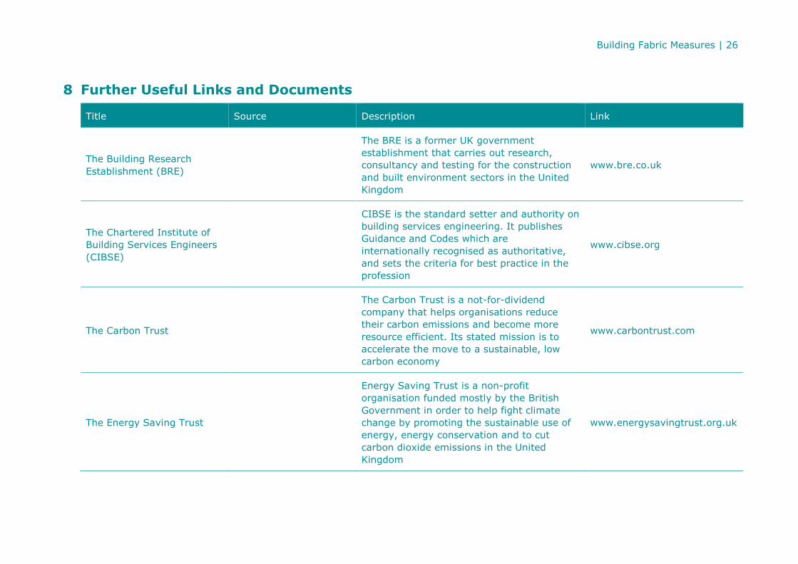
8 Further Useful Links and Documents
Title Source Description Link
The Building Research
Establishment (BRE)
The BRE is a former UK government
establishment that carries out research,
consultancy and testing for the construction
and built environment sectors in the United
Kingdom
www.bre.co.uk
The Chartered Institute of
Building Services Engineers
(CIBSE)
CIBSE is the standard setter and authority on
building services engineering. It publishes
Guidance and Codes which are
internationally recognised as authoritative,
and sets the criteria for best practice in the
profession
www.cibse.org
The Carbon Trust
The Carbon Trust is a not-for-dividend
company that helps organisations reduce
their carbon emissions and become more
resource efficient. Its stated mission is to
accelerate the move to a sustainable, low
carbon economy
www.carbontrust.com
The Energy Saving Trust
Energy Saving Trust is a non-profit
organisation funded mostly by the British
Government in order to help fight climate
change by promoting the sustainable use of
energy, energy conservation and to cut
carbon dioxide emissions in the United
Kingdom
www.energysavingtrust.org.uk
Building Fabric Measures | 27
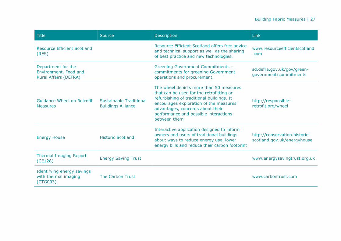
Title Source Description Link
Resource Efficient Scotland
(RES)
Resource Efficient Scotland offers free advice
and technical support as well as the sharing
of best practice and new technologies.
www.resourceefficientscotland
.com
Department for the
Environment, Food and
Rural Affairs (DEFRA)
Greening Government Commitments -
commitments for greening Government
operations and procurement.
sd.defra.gov.uk/gov/green-
government/commitments
Guidance Wheel on Retrofit
Measures
Sustainable Traditional
Buildings Alliance
The wheel depicts more than 50 measures
that can be used for the retrofitting or
refurbishing of traditional buildings. It
encourages exploration of the measures’
advantages, concerns about their
performance and possible interactions
between them
http://responsible-
retrofit.org/wheel
Energy House Historic Scotland
Interactive application designed to inform
owners and users of traditional buildings
about ways to reduce energy use, lower
energy bills and reduce their carbon footprint
http://conservation.historic-
scotland.gov.uk/energyhouse
Thermal Imaging Report
(CE128) Energy Saving Trust www.energysavingtrust.org.uk
Identifying energy savings
with thermal imaging
(CTG003)
The Carbon Trust www.carbontrust.com

Building Fabric Measures | 28
Low Carbon Refurbishment
of Buildings - A guide to
achieving carbon savings
from refurbishment of non-
domestic buildings (CTV038)
The Carbon Trust www.carbontrust.com
Central Government –
Making carbon savings go
further in the Government
Estate (CTV029)
The Carbon Trust www.carbontrust.com
How to conduct a walk-
around energy survey
(CTL003)
The Carbon Trust www.carbontrust.com
Building fabric - Energy
saving techniques to
improve the efficiency of
building structures
(CTV069)
The Carbon Trust www.carbontrust.com
Energy Efficiency in
Buildings CIBSE
The Guide shows how to improve energy
performance, reduce running costs and
minimise the environmental impact of
buildings. Section 18 covers energy audits
and surveys
www.cibse.org
Fabric Improvements for
Energy Efficiency in
Traditional Buildings
Historic Scotland
This guide presents a series of practical
solutions to improving energy efficiency in
traditional and historic buildings, through a
range of fabric improvements measures to
different elements of a traditionally
constructed building
www.historic-scotland.gov.uk
Building Fabric Measures | 29
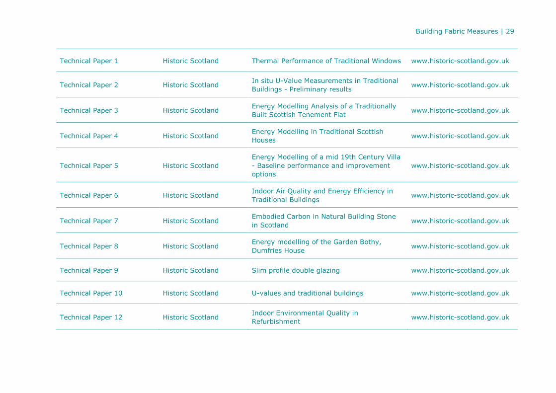
Technical Paper 1 Historic Scotland Thermal Performance of Traditional Windows www.historic-scotland.gov.uk
Technical Paper 2 Historic Scotland In situ U-Value Measurements in Traditional
Buildings - Preliminary results www.historic-scotland.gov.uk
Technical Paper 3 Historic Scotland Energy Modelling Analysis of a Traditionally
Built Scottish Tenement Flat www.historic-scotland.gov.uk
Technical Paper 4 Historic Scotland Energy Modelling in Traditional Scottish
Houses www.historic-scotland.gov.uk
Technical Paper 5 Historic Scotland
Energy Modelling of a mid 19th Century Villa
- Baseline performance and improvement
options
www.historic-scotland.gov.uk
Technical Paper 6 Historic Scotland Indoor Air Quality and Energy Efficiency in
Traditional Buildings www.historic-scotland.gov.uk
Technical Paper 7 Historic Scotland Embodied Carbon in Natural Building Stone
in Scotland www.historic-scotland.gov.uk
Technical Paper 8 Historic Scotland Energy modelling of the Garden Bothy,
Dumfries House www.historic-scotland.gov.uk
Technical Paper 9 Historic Scotland Slim profile double glazing www.historic-scotland.gov.uk
Technical Paper 10 Historic Scotland U-values and traditional buildings www.historic-scotland.gov.uk
Technical Paper 12 Historic Scotland Indoor Environmental Quality in
Refurbishment www.historic-scotland.gov.uk
Building Fabric Measures | 30
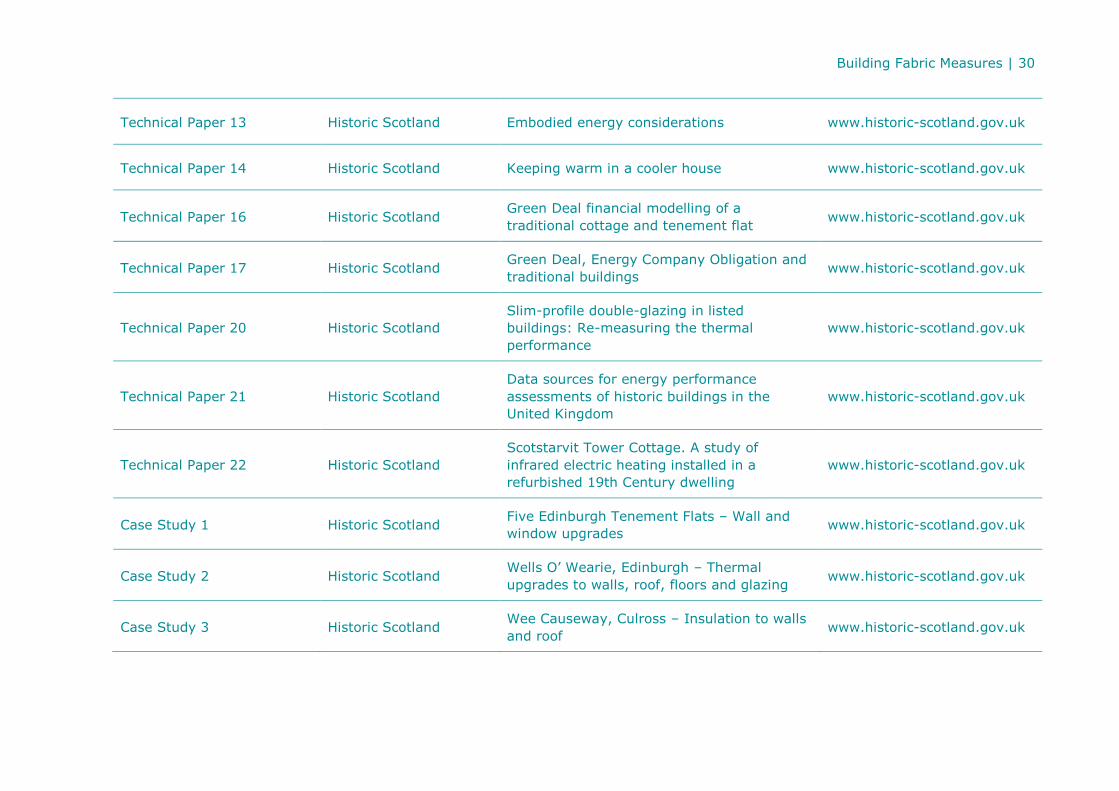
Technical Paper 13 Historic Scotland Embodied energy considerations www.historic-scotland.gov.uk
Technical Paper 14 Historic Scotland Keeping warm in a cooler house www.historic-scotland.gov.uk
Technical Paper 16 Historic Scotland Green Deal financial modelling of a
traditional cottage and tenement flat www.historic-scotland.gov.uk
Technical Paper 17 Historic Scotland Green Deal, Energy Company Obligation and
traditional buildings www.historic-scotland.gov.uk
Technical Paper 20 Historic Scotland
Slim-profile double-glazing in listed
buildings: Re-measuring the thermal
performance
www.historic-scotland.gov.uk
Technical Paper 21 Historic Scotland
Data sources for energy performance
assessments of historic buildings in the
United Kingdom
www.historic-scotland.gov.uk
Technical Paper 22 Historic Scotland
Scotstarvit Tower Cottage. A study of
infrared electric heating installed in a
refurbished 19th Century dwelling
www.historic-scotland.gov.uk
Case Study 1 Historic Scotland Five Edinburgh Tenement Flats – Wall and
window upgrades www.historic-scotland.gov.uk
Case Study 2 Historic Scotland Wells O’ Wearie, Edinburgh – Thermal
upgrades to walls, roof, floors and glazing www.historic-scotland.gov.uk
Case Study 3 Historic Scotland Wee Causeway, Culross – Insulation to walls
and roof www.historic-scotland.gov.uk
Building Fabric Measures | 31
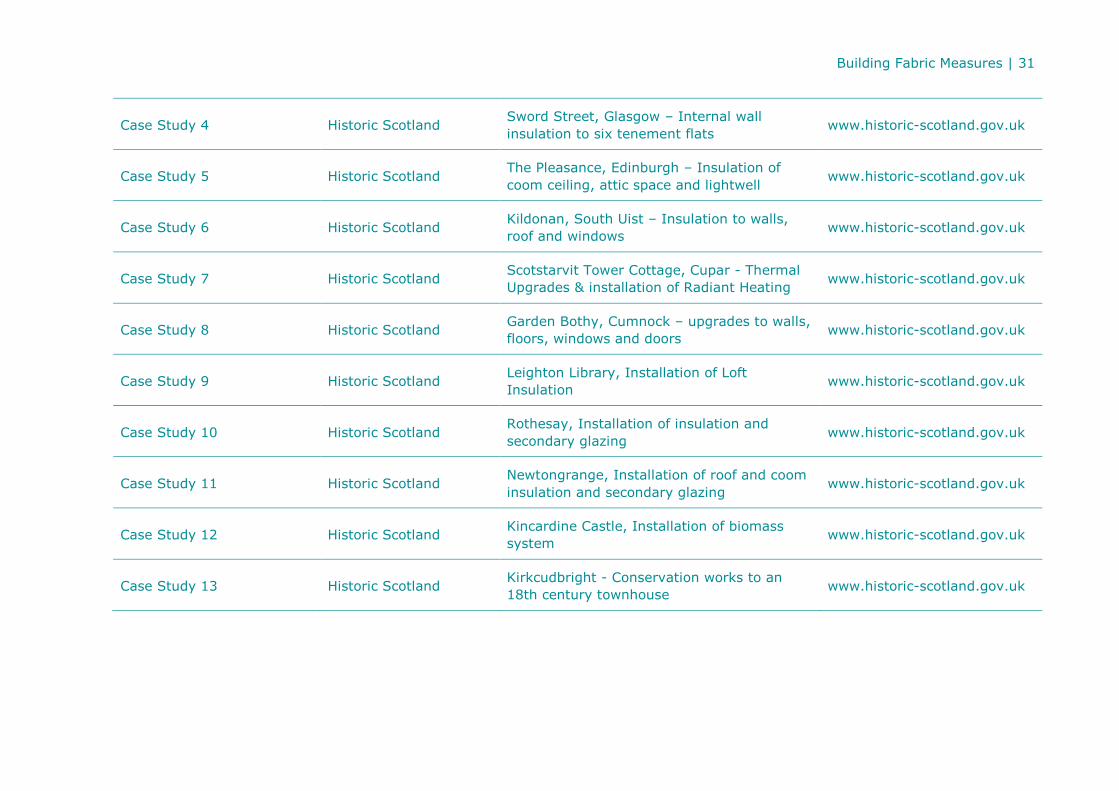
Case Study 4 Historic Scotland Sword Street, Glasgow – Internal wall
insulation to six tenement flats www.historic-scotland.gov.uk
Case Study 5 Historic Scotland The Pleasance, Edinburgh – Insulation of
coom ceiling, attic space and lightwell www.historic-scotland.gov.uk
Case Study 6 Historic Scotland Kildonan, South Uist – Insulation to walls,
roof and windows www.historic-scotland.gov.uk
Case Study 7 Historic Scotland Scotstarvit Tower Cottage, Cupar - Thermal
Upgrades & installation of Radiant Heating www.historic-scotland.gov.uk
Case Study 8 Historic Scotland Garden Bothy, Cumnock – upgrades to walls,
floors, windows and doors www.historic-scotland.gov.uk
Case Study 9 Historic Scotland Leighton Library, Installation of Loft
Insulation www.historic-scotland.gov.uk
Case Study 10 Historic Scotland Rothesay, Installation of insulation and
secondary glazing www.historic-scotland.gov.uk
Case Study 11 Historic Scotland Newtongrange, Installation of roof and coom
insulation and secondary glazing www.historic-scotland.gov.uk
Case Study 12 Historic Scotland Kincardine Castle, Installation of biomass
system www.historic-scotland.gov.uk
Case Study 13 Historic Scotland Kirkcudbright - Conservation works to an
18th century townhouse www.historic-scotland.gov.uk

Building Fabric Measures | 32


