Energy Efficiency Best Practice in Housing Domestic ...home-epc.org/pdfs/solid fuel.pdf · Energy...
31
Guidance for installers and specifiers Energy Efficiency Best Practice in Housing Domestic heating: solid fuel systems
Transcript of Energy Efficiency Best Practice in Housing Domestic ...home-epc.org/pdfs/solid fuel.pdf · Energy...

Guidance for installers and specifiers
Energy Efficiency Best Practice in Housing
Domestic heating: solid fuel systems

2
Contents
1. Introduction to Best Practice 3
1.1 Energy efficiency and Best Practice 3
1.2 Energy consumption and emissions 4
2. UK building regulations 5
2.1 England and Wales 5
2.1.1 New buildings 5
2.1.2 Existing buildings 6
2.2 Scotland 7
2.3 Northern Ireland 8
3. Solid fuel and energy use 9
3.1 Fuel types 9
3.2 Smoke control 9
4. Chimneys, hearthsand air supplies 10
5. Space and water heating 11
5.1 Open fires 11
5.2 Roomheaters and stoves 11
5.3 Independent boilers 12
5.4 Cookers 12
6. Central heating andhot water systems 13
6.1 Open and sealed systems 13
6.2 Domestic hot water 13
6.3 Upgrading systems 13
6.4 Dual-fuel (‘link-up’) heating systems 13
6.5 Heat emitters 14
6.6 Circulator pumps 14
7. Controls 15
7.1 Individual controls 15
7.2 Selecting controls for Best Practice 17
7.3 Further control improvements 18
8. Best Practice 19
9. Energy Efficiency 21
9.1 The Standard Assessment Procedure (SAP) 21
9.2 Energy consumption and running costs 22
9.3 Carbon dioxide emissions 22
10. System selection - practical issues 23
11. Installing central heating systems 26
11.1 ‘Competent person’ requirements 26
11.2 Chimneys 26
11.3 Installing controls 26
11.4 Water treatment 27
11.5 Fuel storage 27
12. Commissioning and handover 28
12.1 Commissioning 28
12.2 Advice to the householders 28
12.3 Servicing 28
Appendix A -Definitions of heating controls 29
References 30

3
Section 1 - Introduction to Best Practice
Home energy use is responsible for 28 per cent of UK carbon emissions
which contribute to climate change. By following Best Practice standards,
new build and refurbished housing will be more energy efficient and will
reduce these emissions, saving energy, money and the environment.
This guide is designed to help installers, specifiers and purchasers of solid
fuel appliances to choose the most appropriate system for their needs. It
covers solid fuel appliances which contain a boiler providing hot water for
the space heating and domestic hot water needs of the household. It also
covers room heaters.
Specifically, it offers guidance on the selection of appliances, hot water
storage vessels and controls for those wishing to improve energy efficiency,
reduce running costs and reduce carbon dioxide (CO2) emissions. It
describes the main types of solid fuel heating and hot water appliances
available, the kinds of system to which they can be fitted - as well as the
key points that should be considered when choosing appliances.
When making selections, reference should be made to the relevant building
regulations and manufacturers’ instructions should always be followed.
Information is available on the design of central heating systems(1,5,12).This
document does not deal with the detailed requirements for chimneys or
hearths.
This guide only covers the use of mineral based fuels such as coal,
anthracite, coke, briquettes etc and wood in the form of logs and
briquettes.These fuels are burned in appliances, approved by HETAS, such
as boilers, cookers and roomheaters and also multi-fuel appliances burning
both wood and solid mineral fuels. It does not cover appliances specifically
designed to burn wood pellets or wood chips - a separate guide is planned
for this.
The CO2 emitted as a result of burning wood is closely balanced by the
carbon extracted from the atmosphere in recent times by equivalent tree
growth (there is a small amount due to the industrial activities of tree-
felling, cutting, processing and transportation).The ‘net’ carbon emissions
are therefore small, and this gives an environmental benefit compared to
mineral fuel.
The Solid Fuel Association (www.solidfuel.co.uk), representing the coal and
smokeless fuel industry as well as a number of appliance manufacturers,
provides advice and guidance to consumers, specifiers and the heating trade.
HETAS has been in existence for more than 60 years and is ‘the
independent UK body recognised by DEFRA (Department for Environment
Food and Rural Affairs) for the official testing and approval of domestic
solid fuels, solid fuel burning appliances and associated equipment and
services’. HETAS also covers all solid fuels including wood logs, wood
pellets and wood chips and the appliances to burn them. It publishes an
annual guide to approved solid fuel products and services and maintains a
register of competent heating engineers at www.hetas.co.uk.
1.1 Energy efficiency and Best Practice
The overall energy efficiency of a heating appliance or system determines
to a large extent both the running costs and the associated CO2 emissions.
To achieve Best Practice, appliances with the maximum efficiency should be
chosen.
Over the years, efficiency has generally increased. However, for an
equivalent amount of heat, burning mineral solid fuel produces greater
quantities of CO2 than natural gas, LPG or heating oil.While emissions are
theoretically less than for electricity, the lower efficiency of solid fuel
appliances will often mean in practice they are higher.
The efficiency of an appliance varies according to type and design and will
be influenced by:
• whether it is a closed or open appliance;
• combustion control (i.e. fan, damper, etc);
• turn-down range;
• chimney design;
• ventilation;
• fuel type and quality;
• ignition method.
For a central heating system, key factors include:
• system design - whether fully pumped or semi-gravity (pumped space
heating but gravity-fed domestic hot water);
• system controls;
• the design of the chimney and its position in the dwelling;
• load on the boiler due to the weather;
• sizing of boilers and radiators;
• installation and commissioning;
• ratio of space/water heating;
• system balancing;
• servicing and maintenance intervals.
When older appliances are replaced, newer and more advanced technology
can result in substantial improvements in energy efficiency.
How to use this guide
The guide is set out as follows:
Section 2 explains the building regulations for heating and hot water systems in different parts of the UK.
Sections 3-7 describe the fuels, appliances, systems and controls currently available.
Section 8 provides a ready-made central heating system specification.
Section 9 focuses on the benefits of Best Practice and considerations of energy efficiency.
Section 10 contains comprehensive tables on the practical questions that need to be addressed when selecting appliances and systems.
Section 11 addresses issues concerning installation.
Section 12 gives advice on commissioning, servicing and the information needed by the customer.
The Appendix provides definitions of controls.Note: the superscript numbers in brackets in the text refer to documents listed at the end of this guide.

4
Section 1 - Introduction to Best Practice
1.2 Energy consumption and emissions
Appliances for heating and hot water produce the greatest proportion of
domestic (CO2) emissions.They consume far more energy than household
appliances.
The average household with solid fuel central heating consumes about
23,000 kilowatt-hours (kWh) of energy each year. Of this, 84 per cent is for
heating and hot water.To reduce fuel costs and cut emissions, it is
particularly important to choose efficient boilers and install them in suitably
designed and controlled systems.
Figure 1: Energy use and emissions in homes heatedby solid fuel (anthracite).
Other 16%
Boiler84%
Energy consumption
Other 20%
Boiler80%
CO2 emissions
Other 42%
Boiler58%
Relative costs

U-values measure the rate of heat transfer through materials, in units
of watts per square metre per degree of temperature difference
(W/m2K).The lower the figure, the lower the rate of heat loss.
The Standard Assessment Procedure (SAP) is the UK Government’s
procedure for calculating home energy ratings which enable the
householder to compare the energy performance of different
buildings(15).
The carbon index is calculated as part of the SAP. CO2 is emitted as a
result of burning fuel, or generating electricity, to meet the demand for
space and water heating. Expressed on a scale from 0.1-10.0, higher
values represent lower emissions.
5
Section 2 - UK building regulations
This section outlines the minimum standards for heating efficiency as set
out in the building regulations.The remainder of this guide then
concentrates on Best Practice - a higher standard.
There are different building regulations in England and Wales, Scotland, and
Northern Ireland.All contain provisions for conservation of fuel and power
(2,3,4).These restrict the type of heating system that may be installed in new
dwellings. In the case of England and Wales, new and replacement heating
systems in existing dwellings are also covered.A summary of the main
points of the regulations is given below.
Other parts of the regulations (Part J in England and Wales, Section 6:
Energy, of the Domestic Technical Handbook in Scotland and Part L in
Northern Ireland(8,28,29)) deal with the related issues of the safety of heating
installations and with fuel storage.
2.1 England and Wales The building regulations set a legal requirement to make ‘reasonable
provision for the conservation of fuel and power in dwellings’. However, the
approved guidance notes that ‘there may well be alternative ways of
achieving compliance’ (Part L1) and different strategies can be adopted
provided it can be shown they are at least as good as those given in the
guidance.
2.1.1 New buildings
New dwellings must comply with Part L1 of the Regulations(2).Three
methods of demonstrating compliance are given and these take boiler
efficiencies into account. Only two may be used in the case of solid fuel -
the target U-value and the carbon index methods. In each case, the solid
fuel appliance used should have an efficiency at least as high as that
recommended for its type in the HETAS certification scheme(21).
The ‘target U-value’ methodUnder this method, an average U-value (see panel) is calculated from the
values for the various elements of the building envelope and it must not
exceed a target value for the structure.Where solid fuel appliances are
employed, the nominal target value must be divided by an adjustment factor
of 1.15 to arrive at the final figure.This is to compensate for higher carbon
emissions compared with gas and oil-fired boilers.
The carbon index methodWith the carbon index method (see panel), a value of 8.0 or better must be
achieved.The choice of fuel will have a direct impact on the carbon index.
Storage vesselsHot water storage vessels should be insulated in accordance with BS1566
or BS3198(6,7), and the internal heat exchanger should be sized accordingly.
ControlsZone controls should allow different air temperatures to be set for living
and sleeping areas (other than in small open-plan flats and other properties
where these areas are not separated). In most dwellings, both temperature
zones can be controlled by a single time switch or programmer channel.
However, in properties with a floor area of more than 150m2, multiple
timing zones are required (with no zone larger than 150m2).
PipeworkPipes should be insulated wherever they pass outside the heated living
space. In addition, all hot water pipes connected to the hot water cylinder
(including the vent pipe and the primary flow and return) should be
insulated for at least 1m from the connection.

6
Section 2 - UK building regulations
CommissioningUpon completion of the installation, the systems should be inspected and
then brought into service so that it operates efficiently and meets its
specified performance levels.A commissioning certificate should be made
available to the client and the building control body.The owner or occupier
should also be given information on the operation and maintenance of the
system.
2.1.2 Existing buildings
Part L1 of the Building Regulations applies to work on ‘controlled services
or fittings’ in existing dwellings, as well as in new ones. Certain types of
heating system are ‘controlled’, including central heating systems with
boilers. In particular, any new boiler (whether or not it replaces an existing
unit) should meet or exceed an efficiency recommended for its type in the
HETAS certification scheme(21).
New or replacement hot water storage vessels and controls should meet
the same requirements as in new buildings. Ensuring adequate controls are
in place should be a priority whenever a boiler or hot water storage vessel
is installed. Commissioning and handover procedures should also be
undertaken as in new buildings.

7
Section 2 - UK building regulations
2.2 Scotland From 1 May 2005, new dwellings must comply with the Building (Scotland)
Regulations(3).The methods of demonstrating compliance for new buildings
are similar in principle to those in England and Wales described above,
though there are differences in the calculations.There are three alternative
methods of demonstrating compliance in which the efficiency of the boiler
is taken into account.
The elemental methodMore demanding U-values are involved here when solid fuel appliances are
the main source of heating.
The ‘target U-value’ methodIn the target U-value method, an average U-value is calculated for the
various elements of the building envelope and must not exceed a target
which depends on the ratios of total floor, ground floor, and roof areas to
the total area of all exposed elements of the dwelling.Where solid fuel
appliances are employed, the nominal target value must be divided by an
adjustment factor of 1.15 to arrive at the final figure.This is to compensate
for higher carbon emissions compared with gas and oil-fired boilers.
The carbon index methodIn the carbon index method (see panel - page 5), a result of 8.0 or higher
must be obtained when the overall energy performance of the building is
assessed under SAP.The fuel used for heating and hot water directly affects
the carbon index.
Storage vessels, pipework and controlsHot water storage vessels must be adequately insulated, and all pipes used
for space heating and hot water supply must be suitably insulated where
they lie outside the heated living space.
The space heating system must be controlled by room thermostats or
thermostatic radiator valves (TRVs), and an adjustable seven day time
switch or programmer.A solid fuel boiler must have an automatic control
(thermostat) that reduces firing to the minimum burning rate.
CommissioningAt completion of installation, systems must be inspected, tested, and
brought into service so as to meet the specified performance and operate
efficiently.Written information on the operation and maintenance of the
system must be provided for the occupier.

8
Section 2 - UK building regulations
2.3 Northern Ireland The relevant building regulations are the Building Regulations (Northern
Ireland) 2000, and specifically Regulations F3 and F4.These call for
‘reasonable provisions’ to be made for space heating and hot water supply.
Technical Booklet F: Conservation of fuel and power (December 1998)(4)
gives provisions that are deemed-to-satisfy the requirements of Regulations
F3 and F4.Although it is not essential to follow Technical Booklet F, it is
obligatory to comply with Regulations F3 and F4.
Technical Booklet F has two methods of demonstrating compliance,
explained here. For both methods a SAP rating (see 9.1) must first be
calculated, and different requirements then apply according to whether or
not the SAP rating exceeds 60.
The elemental methodUnder the elemental method, boiler efficiency is not specified explicitly,
although it affects the SAP rating achieved. If the SAP rating is 60 or less
then lower (more onerous) maximum U-values (see panel) are applied to
the elements of the building fabric, which will tend to increase construction
costs.
The ‘target U-value’ methodUnder the target U-value method, the target is calculated by reference to
the total floor area and total area of exposed elements, and raised (i.e.
relaxed) where the SAP rating exceeds 60.The target can be relaxed
further by as much as 10 per cent where there is a high efficiency heating
system.
A heating system with a gas boiler of seasonal efficiency above 72 per cent
qualifies, and between 72 per cent and 85 per cent the target U-value may
be increased by up to 10 per cent pro rata.
Storage vessels, pipework and controlsHot water storage vessels shall be insulated to a specified standard, and all
hot water pipes connected to the vessel (including the vent pipe and
primary flow and return) shall be insulated for at least 1m from the
connection. Other pipes shall be insulated where they lie outside the
heated living space.
The heating and hot water systems shall be controlled by thermostats or
TRVs, allowing for independent zones where different temperatures are
required (e.g. separate sleeping and living areas).
A time switch or programmer shall be provided to control operating
periods.

9
Section 3 - Solid fuel and energy use
3.1 Fuel types The choice of fuel will depend on several factors including:
• type of appliance;
• fuel availability;
• manufacturers' recommendations;
• location of the dwelling (whether in a smoke control area or not).
So-called ‘multifuel’ appliances can burn both mineral fuel and logs. Burning
time of different fuels, as well as ease of ignition, will depend on the
proportion of volatile matter. In the UK, mineral fuels fall into the following
categories.
• Natural smokeless fuels (anthracites).These are very low in volatiles and
burn for long periods.They can be used in a wide variety of appliances,
but are not recommended for open fires unless these are fan-assisted.
Care is needed in selecting the correct size of fuel.
• Manufactured smokeless fuels (coke and briquettes).These also have
low volatility and are suitable for a wide range of applications. If for use
in smoke control areas, they must satisfy the requirements of the Clean
Air Act(11).
• Bituminous coal.This is mainly used in open fires and should not be
used in smoke control areas except in an exempted appliance. Coal
properties vary.
The sale of coal, smokeless fuel and wood is regulated by both the Weights
and Measures Act(9) and the Trades Descriptions Act(10).
3.2 Smoke control A large proportion of dwellings in UK urban areas are in smoke control
zones. Combustion systems have to comply with the Clean Air Act and
appliances have to use authorised smokeless fuel unless they are specifically
designed as smoke-reducing exempt appliances.
Bituminous coal emits higher levels of air pollution when burned and so can
only be used in exempt appliances within smoke control areas. ‘Smokeless
fuels’ such as anthracite, coke and briquettes that meet low emissions
standards may be designated by DEFRA (Department for Environment
Food and Rural Affairs) as ‘approved fuels’ for use in these areas.

10
Section 4 - Chimneys, hearths and air supplies
For the safe and efficient use of any solid fuel appliance, it is essential to
have a well-constructed chimney.This allows combustion products to be
discharged safely to the outside atmosphere. Chimneys are generally
divided into three types:
• existing masonry;
• custom-built;
• factory-made.
Existing masonry chimneysThese may be lined or unlined. Since 1985, all new masonry chimneys
intended to be used with solid fuel have been lined with a suitable material
such as clay. Before that date, proprietary liners were seldom used. Steady
deterioration of the fabric over a period of time means that many chimneys
require secondary lining and there are a number of proprietary techniques
that have been developed for this purpose.
Custom-built and factory-made chimneysNew chimneys can be constructed of traditional materials or pre-fabricated
using factory-made stainless steel or block systems.
Chimney designAll chimney and hearth construction, and the provision of correctly sized
ventilation openings, must satisfy building regulations requirements (Part J in
England & Wales, Section 3: Energy, of the Domestic Technical Handbook in
Scotland and Part L in Northern Ireland).These apply for all solid fuels and
it is essential that a pre-installation check of the chimney is carried out
before any appliance is installed.
Key requirements in chimney design are as follows.
• It must have sufficient height - the temperature difference between flue
gas and outside air provides the necessary updraft or ‘pull’ to expel the
fumes.
• There should be no sharp bends or obstructions which offer resistance
to the flow.
• Air leakage must be minimised to prevent unnecessary cooling of the
flue gases.
• Careful planning of the chimney termination is needed to avoid high
pressure zones.
• All chimneys must have provision for sweeping.
There must also be an adequate air supply to solid fuel appliances in order
to ensure complete combustion of the fuel and the correct functioning of
the chimney. Incomplete combustion leads to increased levels of smoke and
carbon monoxide which is a serious health hazard.
Extractor fans must not be installed in the same room as an open-flue
appliance or the room in which the permanent vent is located.There are
some exceptions to this rule, e.g. in large rooms where there is sufficient
replacement air to avoid spillage of combustion gases (although a spillage
test must be carried out).
It is essential for safe and efficient operation that solid fuel chimneys are
regularly inspected and cleaned.
Solid fuel appliances must be sited on a hearth constructed of suitably
robust materials. Its dimensions should be such that, in normal use, the
building fabric and furnishings are prevented from catching fire.
Further guidance on chimney design, installation and maintenance can be
obtained from: the British Flue and Chimney Manufacturers Association
(BFCMA)(22); the National Association of Chimney Engineers (NACE)(23);
the National Association of Chimney Sweeps (NACS)(24); the Guild of
Master Sweeps(GMS)(25); the Solid Fuel Association (SFA)(18) and HETAS(13).

11
Section 5 - Space and water heating
All solid fuel appliances other than open fires are referred to as closed.
Although they cannot be turned on and off electrically, they can be turned
down when heat is not required. If the appliance includes a boiler, turn
down is effected indirectly by stopping the pump and allowing the boiler
thermostat to reduce the burn rate. Some appliances are fitted with a fan
that enables combustion air to be reduced to a low level.This means the
heat output can also be reduced to a minimum.
5.1 Open firesInset on a hearth, these give a visible fire and are not enclosed by doors or
glass.Although they can burn many types of fuel, they do not have high
thermal efficiency as the combustion air supply cannot be controlled. Heat
is transferred to the room mainly by radiation, so the further from the fire
the less heating effect. Open ‘convector’ fires (both inset and freestanding)
are also available, with heat being transferred from a convection chamber to
the room.These supply more heat than a comparable open fire and are
somewhat more efficient.The ‘dog grate’ (sited in a recess or inglenook) has
become popular over recent years, but is the least efficient of the open fire
configurations because of its large open construction.
Back boiler units (BBUs) can be fitted to an open fire.These will provide
primary hot water which will then serve a domestic hot water cylinder as
well as a radiator heating system. High output open fires with BBU now on
the market will meet the space and water heating requirements of a
traditional three-bedroom house.These are more efficient as they
incorporate throat restrictors to limit the warm air that is drawn from the
room.
Open fires do not have automatic air control to regulate the combustion
rate. Many achieve partial control of air supply by adjusting the air inlet on
the ash pit door and, where fitted, a flue damper. Note that it is a mandatory
requirement that there is a correctly sized air vent so that the fire has
sufficient air for combustion and fume evacuation under all conditions.
While traditional and attractive in appearance, open fires have the
disadvantages of slow response, poor turn down and lack of thermostatic
control.These drawbacks lead to overheating and excessive fuel
consumption. It is possible to fit some open fires with a ‘firefront’, normally
a set of glass doors fitted to the front of the fireplace.This converts the
open fire to a closed unit and will significantly improve its operating
efficiency.The unit may also include thermostatic control.
5.2 Roomheaters and stovesThese consist of a firebox and flue outlet enclosed behind a door of
heatproof glass. By enclosing the fire, combustion air supply can be
effectively controlled.This reduces the excess air entering the chimney and
allows for greater control over the rate of burning.This increases operating
efficiency substantially above that of the simple open fire.
This increased efficiency combined with a traditional and attractive
appearance makes them the most popular type of solid fuel heating
appliance.
Freestanding units coupled to a chimney with a pipe are referred to as
stoves - which should not be confused with cooking appliances.As these
are not built into the chimney breast, they have larger casings and, in some
cases, an extra flue gas pass before discharge. Stoves therefore have cleaner
combustion and higher efficiencies.
Figure 2: An open fire
Output range (kW) Typical turn down
4-10 2.5-3.0 : 1
Open fires
Figure 3: A stove

12
Section 5 - Space and water heating
BackboilersVariants with BBUs are also available. Providing an attractive focal point,
these units are commonly used for solid fuel central heating systems. In
such instances, it is important to ensure the right ratio between ‘heat to
room’ and ‘heat to water’, which should be roughly proportional.The
distribution of heat in the building (particularly within the room where the
unit is located) needs to be carefully considered. If the appliance is over-
sized, heat output to the rest of the dwelling will be limited.
It is common to install a radiator in the same room as the appliance (it
must have a TRV) so that adequate heating is available under most
operating conditions. Sometimes, units have a damper fitted which controls
the heat-to-water and heat-to-air ratio.When the damper is closed, the
heat-to-room is at its maximum.When the damper is fully open, the
greatest heat-to-water is achieved.
Many stoves and roomheaters are ‘multifuel’ appliances that can burn
mineral fuel or wood.The more wood that is used, the lower the CO2
emissions.This is because wood is a carbon-neutral fuel.
5.3 Independent boilers
These can provide full central heating for most dwellings and are available
in a wide range of outputs and sizes. Batch fed units will provide domestic
hot water and sufficient heat for a three to four bedroom house. Gravity-
fed boilers (which have a large hopper over the fire box) will operate for
up to 36 hours at minimum output and for 10 hours on full burn rate
without refuelling or de-ashing.All of them burn small anthracite that feeds
into the fire as necessary. Combustion is assisted by a built-in
thermostatically controlled fan, which helps adjust output to demand.
Gravity-fed units have a high turn down (around 10:1), which means that
they can kindle at low combustion rates, compared with other solid fuel
appliances.There is still some background heat given off when the boiler is
turned down to minimum, helping to prevent condensation within the
dwelling.
5.4 CookersSolid fuel cookers come in a range of types, including: cooker only; cooker
and domestic hot water supply; and those that provide partial or full central
heating.They can burn a wide range of fuels and because of their high
thermal inertia and sustained temperatures they have gained an enviable
reputation for cooking quality.
Their design means that they inevitably produce constant background
warmth and this may make them less suitable in modern housing which
often only needs intermittent heating. Indeed, constant background warmth
can sometimes make ambient temperatures uncomfortable during the
summer.They are better suited to dwellings such as the traditional
farmhouse where daily lifestyle centres around the kitchen.
Output range (kW) Typical turn down
6-12 4.0-5.0 : 1
Roomheaters and stoves
Figure 4: Anindependentboiler
Independent boilers
Output range (kW) Typical turn down
Batch fed 6-12 4.0-5.0 : 1
Gravity fed 13-24 10.0 : 1
Output range (kW) Typical turn down
4-23 4.0-5.0 : 1
Cookers
Figure 5: Cooker with BBU

6.1 Open and sealed systemsSolid fuel boilers and back boilers must be installed in an open-vented
system meeting British Standards(1). Open-vented systems are so-called
because they incorporate a separate vent pipe which is open to the
atmosphere. Sealed systems (which use an expansion vessel) are not used
since it is not possible to turn the heating off.
Open-vented systems also include a feed and expansion cistern to allow for
changes in system water volume with temperature.The cistern must be at
the highest point of the system which is usually in the loft, and protected
from the risk of freezing.
All materials in normal contact with the water (e.g. the cistern, cover and
components) must be capable of withstanding a temperature of 100°C. If
fitted in a roofspace or exposed position, precautions against freezing need
to be taken.
Figure 6 shows a typical pipework arrangement for a fully pumped system
which is suitable for use with a solid fuel boiler.They can also be used in
semi-gravity systems (see Section 7.2).
6.2 Domestic hot waterSystems should include a vented, indirect, double-feed storage cylinder for
hot water.This should meet the relevant British Standards requirements(6)
and, where specified by the heating appliance manufacturer, should be
suitable for gravity operation (even in a fully-pumped system, gravity
circulation should be possible in the event of a control or power failure).
In dwellings with a single bathroom, a cylinder capacity of 120-140 litres is
normally sufficient. Larger houses with more than one bathroom (and with
separate showers) will need a higher capacity. Some manufacturers
recommend the use of larger cylinders as this prevents heat wastage by
providing a store for heat whilst the boiler is in ‘slumber’ mode.
Pre-coated cylinders should always be used in preference to those with
separate jackets. Medium-duty cylinders do not meet building regulations
requirements in England and Wales and should no longer be used in either
new or replacement projects.
Thermal stores can be used to hold water at high temperature and these
are heated by the boiler directly.They are available either for ‘hot water
only’ or ‘hot water and space heating’ operation.
6.3 Upgrading systemsMany existing wet central heating systems are poorly controlled and of
obsolete design. Poor design features which fail to meet Best Practice
requirements include the following.
• Open appliances with poor control of air supply.
• Lack of cylinder thermostat and motorised valve, resulting in excessive
temperatures for stored hot water.
• No room thermostat or TRVs, giving excessive room temperatures.
• Under-sized heat exchanger on the storage cylinder and inadequate
insulation.
Important points to consider when replacing a solid fuel appliance include
the following.
• Where the system is converted to fully pumped, or where a motorised
valve is installed to improve hot water temperature control, system
design must ensure that all the heat generated when the boiler is in
slumber mode is dissipated. In addition, unsafe operation in the event of
power or control failure must be prevented.
• Any slumber radiator incorporated in the system must not be fitted
with user-operated valves or a TRV.
• The chimney must be correctly designed, sized and correctly
constructed using suitable materials. It must also be provided with an
appropriate terminal(2,3,4,5).
• A purpose-made air vent must be included to ensure sufficient
combustion air.
6.4 Dual-fuel (‘link-up’)heating systems
In some circumstances, it is possible to connect a solid fuel boiler (back
boiler or stove) to an open-vented central heating system operating on
another fuel, such as oil or gas.This ‘link-up’ offers the benefits of a dual-
fired system. It has the appearance of a traditional solid fuel fire, together
with possible advantages from reduced running costs and reduced
emissions. However, these have to be carefully weighed against the extra
capital costs involved.
Link-up can be achieved in a number of different ways, depending on the
existing system (if there is one) and the size and output of appliances being
linked. Particular care must be paid to safety, controllability and efficiency. It
is essential to ensure that the solid fuel appliance has an unrestricted open
vent and a separate cold water feed supply.Any motorised valves used must
be of the `normally open’ type to prevent safety problems in the case of
power or component failure.
13
Section 6 - Central heating and hot water systems
Boiler
Figure 6: Schematic of open (vented) system(excluding controls for clarity)
14
Section 6- Central heating and hot water systems
Expert advice should be sought to ensure correct and safe pipework as well
as electrical systems, and that the new system is energy efficient. Special
products for link-up systems are available(18).
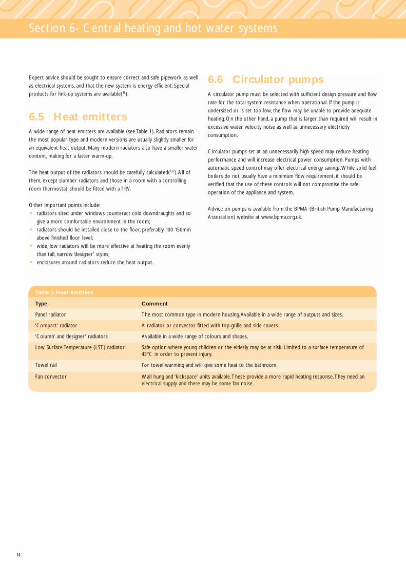
6.5 Heat emittersA wide range of heat emitters are available (see Table 1). Radiators remain
the most popular type and modern versions are usually slightly smaller for
an equivalent heat output. Many modern radiators also have a smaller water
content, making for a faster warm-up.
The heat output of the radiators should be carefully calculated(1,12).All of
them, except slumber radiators and those in a room with a controlling
room thermostat, should be fitted with a TRV.
Other important points include:
• radiators sited under windows counteract cold downdraughts and so
give a more comfortable environment in the room;
• radiators should be installed close to the floor, preferably 100-150mm
above finished floor level;
• wide, low radiators will be more effective at heating the room evenly
than tall, narrow ‘designer’ styles;
• enclosures around radiators reduce the heat output.
6.6 Circulator pumpsA circulator pump must be selected with sufficient design pressure and flow
rate for the total system resistance when operational. If the pump is
undersized or is set too low, the flow may be unable to provide adequate
heating. On the other hand, a pump that is larger than required will result in
excessive water velocity noise as well as unnecessary electricity
consumption.
Circulator pumps set at an unnecessarily high speed may reduce heating
performance and will increase electrical power consumption. Pumps with
automatic speed control may offer electrical energy savings.While solid fuel
boilers do not usually have a minimum flow requirement, it should be
verified that the use of these controls will not compromise the safe
operation of the appliance and system.
Advice on pumps is available from the BPMA (British Pump Manufacturing
Association) website at www.bpma.org.uk.
Table 1: Heat emitters
Type Comment
Panel radiator The most common type in modern housing.Available in a wide range of outputs and sizes.
‘Compact’ radiator A radiator or convector fitted with top grille and side covers.
‘Column’ and ‘designer’ radiators Available in a wide range of colours and shapes.
Low Surface Temperature (LST) radiator Safe option where young children or the elderly may be at risk. Limited to a surface temperature of 43°C in order to prevent injury.
Towel rail For towel warming and will give some heat to the bathroom.
Fan convector Wall hung and ‘kickspace’ units available.These provide a more rapid heating response.They need an electrical supply and there may be some fan noise.

15
Section 7 - Controls
Installing effective controls can have a major impact on the energy
consumption of heating and hot water systems.This section describes the
types of controls now available and outlines which are most appropriate for
different heating systems.
Effective controls will increase operating efficiencies, especially when older
systems are being updated.They also provide the householder with the
opportunity to minimise energy consumption by ensuring the right comfort
temperatures are maintained and so reducing overheating. Reducing room
temperatures will also save energy (see panel).Timed space and water
heating periods will also help to avoid excessive use of energy. Heating fuel
is expensive and reducing the amount of time operating at high output will
make a proportionate difference to running costs.
What is a ‘good’ control system? It is one which ensures the boiler does
not operate unless there is a demand and that only provides heat where
and when it is needed in order to achieve the required temperatures. Most
solid fuel appliances do not turn the heat off, therefore the control system
must ensure that the burning rate is minimised when heat requirements are
low.The selection of appropriate controls plays a key part in minimising the
overall running costs of a heating or hot water system.
To maximise the efficiency of a heating system, control standards must
meet Best Practice.
The cost benefit of controls should not be underestimated. Over 80 per
cent of the energy a householder uses in the home is for space and hot
water heating and the correct use of controls will have a major impact on
consumption.
7.1 Individual controlsThis section describes the range of controls commonly used in heating and
hot water systems, what they do and why they are important.
The controls listed here are normally installed separately from the boiler.
For clarity of specification,Appendix A contains a full list of controls,
including those often fitted within appliances, and gives industry-agreed
definitions.
In the following listing, Best Practice controls are noted.
Time Switch - A simple time control that will only switch one circuit.
It should be chosen so that it is easy to understand and reset, especially
when there is a change to the householder’s domestic routine.
Programmer - This can switch two circuits separately (usually heating
and hot water).There are three basic types:
• a mini-programmer allows space heating and water to be on together,
or hot water alone but not heating alone;
• a standard programmer uses the same time settings for space heating
and hot water;
• a full programmer allows fully independent time setting for space and
hot water heating.
Room thermostat - A simple room temperature control. Most
room thermostats include an accelerator or anticipator, which has the
effect of smoothing out the temperature cycle so that on and off periods
are not too long.Wireless units are now available that provide increased
flexibility in positioning and also eliminate visible wiring (see the following
note on wireless controls).
Programmable room thermostat (Best Practice) -This allows different temperatures to be set for different periods of the day
or week and can provide a good match to householder living patterns
(particularly if occupancy varies during this time).This device also has a
‘night setback’ feature where a minimum temperature can be maintained.
Many of these models are battery-operated and can replace a conventional
thermostat without the need for additional cabling. Some versions also
allow time control of hot water provision.
Cylinder thermostat (Best Practice) - A simple control of
stored hot water temperature, usually strapped to the side of the hot
water cylinder. It is commonly used with a motorised valve to provide
close control of water temperature.
VAT on heating controls
Heating controls for domestic wet central heating systems are
recognised by the Government as an energy efficiency measure.VAT is
therefore charged at a lower rate - currently 5 per cent instead of the
full rate of 17.5 per cent.This lower rate applies to both equipment and
installation costs, but only when the work is carried out by an installer
registered for VAT.
Figure 7:A programmable room thermostatoffers greater flexibility in setting temperaturesand times than a standard room thermostat,producing greater savings
Mid-morningEarlymorning
Afternoon
Roomtemperature
Evening Night
Z
ZZ
ZZ

16
Section 7 - Controls
Pipe thermostat (Best Practice) - This may be fitted to part of
the primary circulation system in order to prevent overheating. It should be
connected electrically so that when activated the pump will dissipate excess
heat in the system (it is typically set to 85°C).A pipe thermostat can also
be used to turn the pump off if the boiler is operating at low temperatures.
Manufacturers often recommend this as a way to prevent corrosion within
the appliance (in which case it is normally set to 45-50°C).
Thermostatic radiator valve (Best Practice) - TRVs are used
to limit the temperature in individual rooms.They also prevent overheating
from solar and other incidental gains. In this way, they cut down on
unnecessary consumption.They must not be fitted to a slumber radiator.
Motorised valve (Best Practice) - This is used to control water
flow from the boiler to heating and hot water circuits.Two-port valves can
also be used to provide zone control (e.g. allowing lower temperatures to
be set for sleeping areas or different heating times).All two-port valves
used in solid fuel systems must be ‘normally open’ (i.e. they only close when
power is applied) to ensure safe operation in the event of power failure or
malfunction.An explanation of different types is given in Appendix A.
Boiler interlock (Best Practice) - This is not a device, but rather a
wiring arrangement to prevent the boiler firing when there is no demand
for heat. It is not possible to switch off the heat output in most solid fuel
systems. The concept of boiler interlock can still be applied in this case.
When there is no demand for heat, the appliance output is reduced to a
minimum.This is the closest practical alternative to on/off control.
The boiler is ‘interlocked’ when its heat output is controlled by thermostats
containing electrical switches.All thermostats in the heating system fitted
with electrical switches should be wired in this way.This includes room
thermostats, programmable room thermostats and cylinder thermostats.
For most solid fuel appliances, the thermostats will switch the pump off,
which in turn will cause the boiler to operate at minimum heat output.
How interlock is achieved will depend on the type of boiler and the
controls fitted. Interlock is usually arranged so that the room or cylinder
thermostat switches the pump directly, or through the motorised valve
end-switch (i.e. when there is a demand for heat, the power from the
thermostat de-energises the valve motor which ‘springs back’ to the open
position). Once the valve is fully open, the end-switch closes and electric
power is then passed to the pump.When power is restored to the valve
(programmer off-period or the thermostat is satisfied) the end-switch
opens and the pump will stop.
Wireless controls
Wireless controls should be designed with adequate immunity to
blocking by other radio transmissions. If not, they may become
unreliable or cease to work at all as nearby radio frequency bands
become increasingly used. See Best Practice Note 7 (in Section 8) for
details on how to specify wireless controls.
Table 2: Control functions
The following control functions are often built into boilers and control units.
Delayed start Reduces energy use by delaying boiler start time when the weather is mild.
Optimum start Adjusts the heating start time to give the required dwelling comfort temperature at a chosen time.
Night setback Allows a low temperature to be maintained at night. Provides improved comfort and reduced dwellingwarm-up time in cold weather.A programmable room thermostat can provide this facility.
Self-adaptive function Reduces appliance ‘on’ time by learning from previous temperature characteristics.
Energy savings from good controls
• Installing a minimum standard of controls on a system which
previously had none can reduce fuel consumption and CO2
emissions by 18 per cent.
• Reducing higher than necessary room temperatures will cut energy
use.Turning down the room thermostat by 1°C will reduce space
heating consumption by 6-10 per cent.
• An easy to use programmer that is adjusted to match the
householder’s occupancy pattern helps reduce wasteful heating
when no one is at home.

17
Section 7 - Controls
7.2 Selecting controls for Best Practice
The system controls and arrangement outlined here is recommended for
Best Practice.All systems should be fully pumped where possible.
Solid fuel appliances cannot usually be switched on and off directly. Effective
control can usually be achieved by operating the pump through a
programmable room thermostat. Control of the hot water should be
achieved with a cylinder thermostat linked to a ‘normally-open’ motorised
valve.An overheat thermostat mounted on the flow pipe can operate the
pump (and motorised valves if necessary) and so dissipate any excess heat.
A low limit thermostat may also be fitted to prevent pump operation when
the temperature is too low (this will help prevent boiler corrosion).TRVs
should be fitted on all radiators except in rooms with a room thermostat
or slumber radiator.
Figure 8 shows a typical controls arrangement for use with a solid fuel
appliance. It should be noted that appliances may have specific requirements
in regard to system design and the use of controls - manufacturers’
instructions should always be followed.
In the event that it is not possible to meet Best Practice requirements, a
semi-gravity system may be employed (Figure 9).The building regulations
require the system to have timing and zone controls.This means that a
programmer or room thermostat (or programmable room thermostat) is
linked to the pump and that TRVs are installed (except in rooms with a
room thermostat or slumber radiator).Where possible, thermostatic
control of domestic hot water should also be installed.
In all cases, the appliance manufacturers’ system installation requirements
must be observed, particularly in regard to the suitability of the appliance
for fully pumped operation.The system design must ensure that all heat
generated when the boiler is slumbering is dissipated and that unsafe
operation is prevented in the event of electricity or control failure.
1
2 34
5
6
7
8
9
123456789
Space heating motorised valveSlumber motorised valveHot water motorised valvePumpHigh limit thermostatLow limit thermostatCylinder thermostatProgrammable room thermostatTRV(s)
Boiler
Slumber radiator
Figure 8: Schematicof a fully-pumpedsystem
1
2
3
4
12345
PumpProgrammable room thermostatLow limit thermostatTRV(s)High limit thermostat
5
Boiler
Slumber radiator
Figure 9: Schematic of asemi-gravity system
18
Section 7 - Controls
7.3 Further control improvements
Zone control- The Best Practice option already includes zone
temperature control, achieved using TRVs. If zones are to be independently
time controlled as well, it will usually be necessary to install additional
room thermostats and a two-port motorised valve (spring-return, ‘normally-
open’) to allow the programmer to shut off water circulation.The wiring in
such situations must be arranged so that boiler interlock works in all zones.
Zone control is particularly beneficial in larger, poorly insulated buildings.
Building regulations in England and Wales require that no zone is larger than
150m2 in floor area and each zone should be capable of independent time
and temperature control.
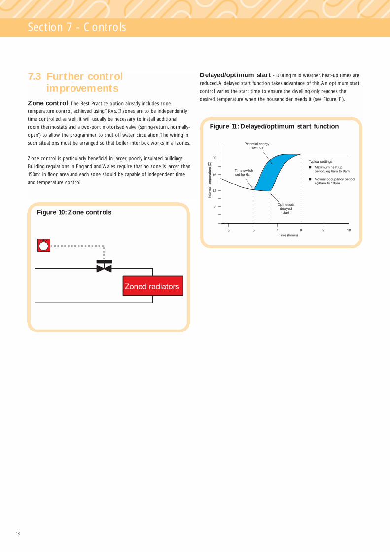
Delayed/optimum start - During mild weather, heat-up times are
reduced.A delayed start function takes advantage of this.An optimum start
control varies the start time to ensure the dwelling only reaches the
desired temperature when the householder needs it (see Figure 11).
Figure 10: Zone controls
Potential energy savings
Time switchset for 6am
Optimised/delayed
start
Typical settings
Time (hours)8765
8
12
16
20
Inte
rnal
tem
per
atur
e (C
)
9 10
Figure 11: Delayed/optimum start function

19
Section 8 - Best Practice
This guide covers most types of solid fuel appliance but concentrates on
Best Practice.The most efficient appliances should be used to provide
optimum performance with low running costs and reduced CO2 emissions.
Best Practice requires:
• closed appliances that meet agreed minimum efficiency and emissions
standards;
• appliances are to be sited in regularly used heating areas;
• the chimney should preferably be located near the centre of the
dwelling;
• the appliances should not be used in summer when only domestic hot
water is needed (although at the margins of the heating season it may
be appropriate to use it for this purpose).
This section outlines a ready-made specification for purchasing the
components that critically affect the energy efficiency of a solid fuel wet
central heating system. Following them will improve energy efficiency and
reduce carbon emissions. However, appliance manufacturers’
recommendations for system design and the installation of controls should
always be adhered to.
Installers can use this specification to quote for systems of defined quality,
comparable with those of their competitors.
Recommended Best Practice (2005)
Description Domestic wet central heating system with soild fuel boiler and separate hot water store, for use with mineral fuel.
Appliance • Designed for use with mineral fuel or wood fuel in the form of logs or briquettes.
HETAS approved appliance or equivalent (HETAS approved appliances are listed in ‘the official guide to approved
solid fuel products and services’ (21).Types are:
- independent boiler;
- stove/roomheater with boiler;
- cooker with central heating boiler.
All appliances must include a temperature thermostat which automatically adjusts combustion to maintain a set
water temperature to within 2°C.
Hot water store • High Performance Hot Water Cylinder (see Note 4)
Controls • Boiler thermostat (see ‘Appliance’ above) (see Notes 5, 6, 7).
• Programmable room thermostat.
• Cylinder thermostat.
• Boiler high temperature pipe thermostat.
• Boiler low temperature pipe thermostat (if required).
• Boiler interlock (see Note 8).
• TRVs on all radiators, except in rooms with a room thermostat or slumber radiator.
• Motorised valves (must be ‘normally-open’ type).
Feed and • The tank and all materials in contact with the water (e.g. the tank cover, ball valve, float) shall be capable of
Expansion tank withstanding a temperature of 100°C.
Installation See Notes 1, 2
Where it is not possible or practical to install the appliance in a fully
pumped system, a semi-gravity system is acceptable providing controls as
above are incorporated. It should be noted that most solid fuel appliances
have specific requirements for system design and the use of controls and
manufacturers instructions must always be followed.

20
Section 8 - Best Practice
1. Other components: The specifications list only the principal
components of a heating system affecting energy efficiency. Other
components will be required, such as radiators, circulator pumps and
cisterns (feed and expansion tanks).All components must be selected
and sized correctly.
2. Design and installation: Heating systems should be designed and
installed in accordance with relevant safety regulations, manufacturers’
instructions, building regulations(2,3,4), and British Standards(1,5,13).
3. Boiler size and type: The whole house boiler sizing method for
houses and flats gives guidance on boiler size and is available on the
website www.boilers.org.uk.Although SEDBUK (Seasonal Efficiency of a
Domestic Boiler in the UK) efficiency information is not applicable to
solid fuel boiler systems, the section ‘Recommended boiler size’ can be
used. Note the comment in Section 5.2 - when sizing room heaters and
stoves ensure the appropriate ratio of ‘heat to room’ and ‘heat to water’
is determined.
4. Hot water cylinder: Hot water cylinder:Vented cylinders shall comply
with BS 1566:2002 (where specified)(6).
5. Circuits and zones: Circuits and zones: Systems must have separately
controlled circuits to the hot water cylinder and radiators, and both
circuits must have pumped circulation. Large properties must be divided
into zones not exceeding 150m2 floor area, so that the operation of the
heating in each zone can be timed and temperature controlled
independently.
6. Definitions of heating controls are given in Appendix A.
7. Wireless controls should be designed with a satisfactory level of
immunity to blocking by other radio transmissions. Otherwise they may
become unreliable, or cease to work, as nearby radio frequency bands
become increasingly heavily used for mobile phone and other
communication services.
Compliance with the essential requirements of the European Radio and
Telecommunications Terminal Equipment (RTTE) Directive 1999/5/EC is
insufficient, as the directive is designed only to ensure that wireless
products do not cause harmful interference to other transmissions. It
does not give any assurance that the product has a satisfactory level of
immunity to interference from other radio transmissions.
Consequently it is not sufficient for the manufacturer to confirm
compliance with the RTTE Directive.The manufacturer should also
confirm that the switching range (and preferably alignment range) does
not include any frequencies below 430MHz, and that in regard to ETSI
EN 300 220-1 v1.3.1 (see Ref[15]) the receiver classification (clause 4.1.1)
is either Class 1 or Class 2, and the device is marked in accordance with
clause 4.3.4.
8. Boiler interlock is not a physical device but an arrangement of the
system controls (room thermostats, programmable room thermostats,
cylinder thermostats, programmers and time switches) so as to ensure
that the appliance does not operate when there is no demand for heat.
Most solid fuel appliances are designed for continuous high/low
operation (not on/off) and therefore boiler interlock should allow the
appliance to operate at minimum rate. In a system which has a boiler
with a boiler thermostat, it can be achieved by correct wiring
interconnection of the room thermostat, cylinder thermostat, and
motorised valve(s) and pump. It may also be achieved by more advanced
controls, such as a boiler energy manager.

21
Section 9 - Energy efficiency
This guide provides information designed to lead to improved energy
efficiency. Selection of the most suitable and energy-efficient appliances is
vital to that process.Appliance selection should consider:
• the seasonal (i.e. annual in-use) efficiencies of the different options;
• the typical running costs for heating and hot water in the dwellings
concerned;
• the typical CO2 emissions associated with space and water heating.
The Standard Assessment Procedure (SAP) is used to assess the overall
energy efficiency of new and refurbished dwellings(15) and the result is
affected by the type of heating system chosen.The SAP document provides
average seasonal efficiency values based on the gross calorific value of the
fuel used (see Table 3).
Case emissions from a solid fuel appliance are generally high and so there is
a noticeable difference between the efficiencies (i.e. of useful delivered
energy) in heated and unheated areas.The chimney also has a heat storage
effect. For Best Practice it is essential that appliances are located in a room
that the householder regularly wants to heat.
To indicate the comparative efficiencies of different appliance types,Table 4
shows the laboratory test efficiencies based on gross calorific value of
mineral fuel. However, these should not be compared with seasonal
efficiencies because they do not take account of the variation in operating
conditions through the year, nor the potential heat gains from the chimney.
9.1 The Standard Assessment Procedure (SAP)
Home energy ratings are designed to give an indication of the energy
efficiency of a dwelling and so allow householders to compare different
homes.The SAP is the Government’s chosen rating system and indicates
the running costs of space and water heating.The building regulations
require all new dwellings to be assessed in this way.
SAP ratings are expressed on a scale of 1-120, with higher figures
representing greater efficiency and lower running costs.The actual figure
depends on certain characteristics of the building and its heating systems, in
particular:
• building design;
• insulation levels;
• solar heat gains;
• ventilation;
• heating and hot water efficiency and controls.
Table 3 shows the seasonal efficiencies used in SAP 2001 for solid fuel
central heating.The values have been used to calculate the energy
consumption and CO2 emissions shown in Tables 5 and 6.
Table 3: Central heating seasonal efficiencies (Source: SAP)
* BBU refers to Back Boiler Unit
Appliance type As refered to in SAP 2001 Seasonal efficiency (%)
Independent boiler Manual feed (in heated space) 60
Independent boiler Manual feed (in unheated space) 55
Independent boiler Autofeed (in heated space) 65
Independent boiler Autofeed (in unheated space) 60
Open fire with BBU* Open fire with back boiler to rads 55
Stove/roomheater with BBU* Closed fire with back boiler to rads 65
Table 4:Typical appliance efficiencies (based on gross calorific value - CV - of burning anthracite)
Type Description (%) Test Efficiency (gross CV)
Typical HETAS minimum
Room heating Open fire (to BS 4834) 43 37
Stove 73 65
Space and water heating Open fire with (high output) BBU 73 65
Cooker with (high output) BBU 72 60
Independent boiler 78 70

22
Section 9 - Energy efficiency
9.2 Energy consumption and running costs
Table 5 gives typical annual fuel costs for some of the more common types
of dwelling found in the UK - both existing properties and new buildings.
They are typical of the existing housing stock(17).The new housing has the
same floor areas, but is built with insulation levels that would satisfy the
latest building regulations for gas heating.The flat is on the top floor. Hot
water costs are related to a typical number of occupants.
Figures shown assume average UK weather conditions (the Midlands).
Consumption would be around 3-6 percent lower in the south and 3-6 per
cent higher in the north.
Typical energy consumption has been calculated using the BRE Domestic
Energy Model, BREDEM-12(16), which estimates annual domestic energy
usage associated with: house design, insulation levels, local climate, and type
of heating system, including efficiency and heating usage.The model is widely
used for calculating running domestic fuel running costs.
Fuel costs have been taken from the 2001 edition of the SAP (Table 12):
• house coal - 1.66 p/kWh
• anthracite - 1.86 p/kWh
• smokeless fuel - 2.69 p/kWh
These costs do not include maintenance or circulating pump running costs.
Table 5: Annual fuel costs for heating and hot water in different property types
EXISTING HOUSING NEW HOUSINGBoiler type (closed appliance Seasonal Flat Bungalow Terraced Semi- Detached Flat Bungalow Terraced Semi- Detachedinstalled in heated space) efficiency Detached Detached
Batch feed (house coal) 60% £257 £336 £350 £396 £562 £84 £105 £105 £131 £156Batch feed (anthracite) 60% £287 £375 £391 £442 £627 £93 £117 £117 £146 £174Batch feed (smokeless fuel) 60% £414 £542 £565 £640 £907 £135 £170 £170 £211 £252Gravity feed (anthracite) 65% £265 £346 £361 £408 £579 £86 £108 £108 £135 £161
9.3 Carbon dioxide emissions Table 6 shows typical values, in tonnes of CO2 per year, of emissions for
the same types of dwellings as those in Table 5. Carbon intensity values are
taken from SAP 2001 Table 15.
Table 6: CO2 emission (tonne/yr) for solid fuel heating and hot water in different property types
EXISTING HOUSING NEW HOUSINGBoiler type (closed appliance Seasonal Flat Bungalow Terraced Semi- Detached Flat Bungalow Terraced Semi- Detachedinstalled in heated space) efficiency Detached Detached
Batch feed (house coal) 60% 4.50 5.89 6.13 6.95 9.85 2.09 2.63 2.63 3.28 3.90Batch feed (anthracite) 60% 4.88 6.40 6.66 7.55 10.70 2.27 2.86 2.86 3.56 4.24Batch feed (smokeless fuel) 60% 6.05 7.92 8.25 9.35 13.25 2.81 2.54 3.54 4.41 5.25Gravity feed (anthracite) 65% 4.51 5.90 6.15 6.97 9.87 2.09 2.64 2.64 3.29 3.92

23
Section 10 - System selection - practical issues
Choosing the right central heating system involves determining:
• the heating and hot water requirements of the household;
• the type of boiler to use and where it should be positioned;
• the type of heating and hot water system;
• the controls to be installed.
There are also a number of practical decisions to be taken. In this section
they are considered in a simple and logical manner.The key questions to be
addressed are as follows.
1 What appliance should be chosen?
2 What size appliance is required?
3 Where will the system be positioned?
4 What chimney arrangements are required?
5 What are the ventilation requirements?
6 What are the central heating system requirements?
7 What type and size of heat emitters are required?
8 What central heating controls are needed?
Room heating only Use HETAS approved closed appliance preferably with thermostatic control.
Wet central heating Use HETAS approved closed appliance with thermostatic control.
Open fire with BBU The simpler open fire is the least efficient in operation and not recommended. High efficiency open firesare available. Converting an open fire using a ‘firefront’ will increase efficiency.
Stove with BBU Provides reasonably high efficiency providing an appliance with thermostatic control is selected.
Independent boiler Have the highest efficiency and capable of the greatest turn-down.
Cooker with BBU This has a relatively high standby loss and may result in uncomfortable ambient temperatures in summer.
10.1What appliance should be chosen? (5,18)
Size for maximum load A boiler should be sized so that it can satisfy the maximum load imposed by the heat emitters,hot water system and distribution pipework.
New heating systems A full design heat loss method should be employed to ensure the most appropriate boiler is selected.
Boiler replacements Size for size replacement is not recommended.The heating and hot water requirements should beascertained before the new boiler is ordered, since insulation levels may have increased, or the original sizing may have been incorrect. Oversizing will lead to less efficient operation as well as increased capitalcost.An interactive procedure for boiler sizing up to 25kW is provided at www.boilers.org.uk.
Roomheaters/stoves Where back boiler units are included, care must be given to ensure the correct 'heat-to-room' and`heat-to-water' ratio is achieved.
10.2 What size appliance is required? (1,12,19,26)
Space Is it adequate - including space for chimney and hearth?
Access Is this adequate for installation, maintenance and servicing?
Chimney Will the appliance be in a suitable position to connect to an existing or new chimney? The chimneyshould preferably be located near the centre of the house.
Hearth This must comply with building regulations.
In a heated area? Preferable - saves energy.
In a unheated area? This will result in undesirable heat loss.
10.3 Where will the system be positioned? (1,2,3,4,5,18)
24
Section 10 - System selection - practical issues
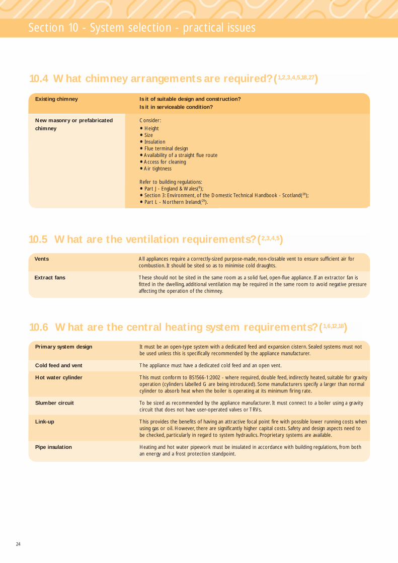
10.4 What chimney arrangements are required? (1,2,3,4,5,18,27)
Existing chimney Is it of suitable design and construction?
Is it in serviceable condition?
New masonry or prefabricated Consider:
chimney • Height
• Size
• Insulation
• Flue terminal design
• Availability of a straight flue route
• Access for cleaning
• Air tightness
Refer to building regulations:
• Part J - England & Wales(8);
• Section 3: Environment, of the Domestic Technical Handbook - Scotland(28);
• Part L - Northern Ireland(29).
10.5 What are the ventilation requirements? (2,3,4,5)
Vents All appliances require a correctly-sized purpose-made, non-closable vent to ensure sufficient air for combustion. It should be sited so as to minimise cold draughts.
Extract fans These should not be sited in the same room as a solid fuel, open-flue appliance. If an extractor fan is fitted in the dwelling, additional ventilation may be required in the same room to avoid negative pressure affecting the operation of the chimney.
10.6 What are the central heating system requirements? (1,6,12,18)
Primary system design It must be an open-type system with a dedicated feed and expansion cistern. Sealed systems must not be used unless this is specifically recommended by the appliance manufacturer.
Cold feed and vent The appliance must have a dedicated cold feed and an open vent.
Hot water cylinder This must conform to BS1566-1:2002 - where required, double feed, indirectly heated, suitable for gravity operation (cylinders labelled G are being introduced). Some manufacturers specify a larger than normal cylinder to absorb heat when the boiler is operating at its minimum firing rate.
Slumber circuit To be sized as recommended by the appliance manufacturer. It must connect to a boiler using a gravity circuit that does not have user-operated valves or TRVs.
Link-up This provides the benefits of having an attractive focal point fire with possible lower running costs when using gas or oil. However, there are significantly higher capital costs. Safety and design aspects need to be checked, particularly in regard to system hydraulics. Proprietary systems are available.
Pipe insulation Heating and hot water pipework must be insulated in accordance with building regulations, from both an energy and a frost protection standpoint.

25
Section 10 - System selection - practical issues
10.7 What type and size of heat emitters are required? (1,12,18,19)
Heat emitter type Panel radiators offer the lowest cost option. Use Low Surface Temperature (LST) radiators where young children or elderly are likely to be present and may be at risk.
Size Use full design heat loss calculations.Avoid undersizing as this will result in unsatisfactory heating performance.Visit www.centralheating.co.uk for more information.
Slumber radiator This must be sized to dissipate excess heat and must not include user-operable valves to flow and return connections.
10.8 What central heating controls are needed? (1,12)
Best Practice Use fully-pumped systems where possible and practical.
TRVs These should be installed on all radiators. Except in rooms with a room thermostat or that include gravity (slumber) radiators.
Pumps Advice on pump selection is available at www.bpma.org.uk. See Section 6.6 in relation to pumps with automatic speed control.
Very large dwellings These should be divided into separate zones not exceeding 150m2 in floor area. Each zone should be capable of independent time and temperature control.
Other controls Additional controls can be beneficial - see Section 7.3.

26
Section 11 - Installing central heating systems
11.1 ‘Competent person’requirements
In England and Wales, the installation or replacement (or alteration to the
position) of a solid fuel combustion appliance is subject to building
regulations.A ‘competent person’ undertaking an installation is required to
complete a HETAS Installation and Commissioning Certificate which
provides details of the installation.A signed copy of this certificate is sent to
HETAS, a copy is left with the owner of the dwelling and a copy is retained
for the installing company’s records. From the 1 April 2005 HETAS will
additionally send an electronic version of this certificate to the Local
Authority Building Control Department.An individual registered under the
Solid Fuel Registration Scheme run by HETAS is deemed competent to
install solid fuel equipment and can undertake this work.Alternatively
installers or their customers can use the Local Authority Building Control
route for notification for which a charge is made.
Other parts of the United Kingdom are considering the adoption of similar
arrangements.
11.2 ChimneysFor installation issues relating to chimneys, refer to information in the
building regulations and also to the advice available from manufacturers,
BFCMA, NACE, the Solid Fuel Association and the HETAS ‘Guide’.
11.3 Installing controlsThe main issues to be considered when installing the most commonly used
domestic central heating controls are described in this section.
Programmable Room ThermostatBest Practice specification
A programmable room thermostat should be located in a regularly heated
area.While free movement of air is important, it should be mounted away
from draughts, internal heat sources and direct sunlight. It should not be
fitted in a room where supplementary room heating (such as electric
heaters or open fires) can affect it. So do not site one in a kitchen or
combined kitchen/living room. Only install one in a main living room if it is
certain that no supplementary heating is used there.Appropriate positions
would be in the hall or a living room without supplementary heating.
The unit should be readily accessible to the householder, not hidden away
in a cupboard or behind furniture. It should be located at a height of about
1.5m above floor level (unless the occupants include wheelchair users,
where a suitable height in excess of 1m should be agreed with the
homeowner).
Time switch/programmerBasic systems only
Time switches can only switch one circuit, while programmers can
control two (e.g. heating and hot water), so ensure that the unit is
appropriate.
These controls should be installed where they can be easily reached, read
and altered. Do not fit them in places inconvenient for the householder
(e.g. in an airing cupboard).
Room thermostatBasic systems only
Installation considerations are the same as for the
programmable room thermostat.
Cylinder thermostatBest Practice specification
This control is usually strapped onto the cylinder about one third of the
way up from the base - the strap needs to be tight to ensure good thermal
contact. It should be adjusted to about 60°C: if set too high, it may result in
scalding, but if too low it can increase the risk of legionella bacteria which
could result in serious health problems(1,20).
Motorised valveBest Practice specification
Solid fuel systems must include ‘normally-open’ motorised valves so that
gravity circulation can be maintained in the event of a control or power
failure. Motorised valves must not be positioned in the line of the open
safety vent pipe or the feed-and-expansion pipe.
Thermostatic Radiator Valve (TRV)Best Practice specification
TRVs must be used in systems meeting either specification.They should be
installed in all rooms - except those in which a controlling room
thermostat provides a boiler interlock. Many TRVs can be fitted on the flow
or return to the radiator and many are bi-directional (if not, the direction
of the water flow must be taken into account when installing them).

27
Section 11 - Installing central heating systems
11.4 Water treatmentNew and existing systems must both be cleaned and flushed before use. A
suitable corrosion inhibitor should also be used to prevent a build-up of
scale and corrosion.The appliance manufacturer’s recommendations must
be followed in this area as damage may result from unsuitable treatment.
For both new and replacement systems, cleaning is essential and, if
recommended in the appliance manufacturer’s instructions, a suitable
chemical cleaning agent can be used.When a boiler is replaced it is essential
to drain and flush all old water from the system in case it contains a
corrosion inhibitor unsuitable for the replacement. Further advice on the
need for treatment, and on causes of problems and methods of treatment
can be found in publications listed at the end of this document(1,20).
11.5 Fuel storageThere should be a weatherproof, robust fuel store with easy access for
delivery and removal of fuel.The store should be capable of containing at
least six weeks supply (for mineral fuel this should be at least 0.5 tonne).
The opening through which the fuel is tipped should be not less than 0.6m2
and not more than 1.4m high.

28
Section 12 - Commissioning and handover
12.1 CommissioningWhen a new or replacement system (including the appliance) is installed it
is important to verify that it is functioning safely and efficiently.
• The installation must be checked for compliance with the building
regulations and an installation and commissioning certificate issued -
completed by the ‘competent person’ in England and Wales.A suitable
certificate is available to members of the Competent Persons
Registration Scheme.
• A notice plate with the performance characteristics of the hearth,
fireplace, flue and chimney is to be fixed in an appropriate place in the
dwelling.This plate is available from a number of sources.
• Confirmation should be sought from the local authority on whether the
installation is covered by a ‘smoke control order’. If so, the fuel used
must be an authorised ‘smokeless’ fuel or the appliance must be an
appliance exempted by DEFRA under the Clean Air legislation.
• The boiler and system should be cleaned using a recognised flushing
procedure.
• The key appliance and systems components should be checked for
proper operation and controls set to optimum settings.
• The customer should be instructed on how to operate the controls, the
importance of servicing the appliance and the system regularly, and of
the need for chimney sweeping at the intervals recommended for the
type of fuel burned.
12.2 Advice to the householdersInstallers must instruct the householder how to set and use the controls
properly and effectively. In particular, the operation of programmers can be
difficult to understand and homeowners will gain little or no benefit from
an incorrectly set device. Indeed, they will probably end up wasting energy.
As a bare minimum, the manufacturer’s instructions should be left with the
householder. However, it will usually be necessary to demonstrate:
• how to set the programmer clock and adjust for GMT and BST;
• the use of the time control override function;
• how to set room and cylinder thermostats;
• how to set TRVs.
The installer will also need to explain:
• the function of room thermostats and TRVs (for example, that they
should be left alone once set, rather than used as on/off switches);
• the correct procedure for emptying the ash pan and cleaning the
appliance;
• that the cylinder thermostat needs to be left at approximately 60°C,
since setting it higher may result in scalding while setting it lower can
allow the growth of legionella bacteria;
• that the radiator lockshield valves should not be adjusted once set by
the installer;
• why it is best to turn off solid fuel appliances when only water heating
is required;
• why it is best to turn the room thermostat down to frost protection
levels (typically around 12°C) when the dwelling is unoccupied (unless a
separate frost protection system has been fitted);
• what may happen to the system if there is a power cut.
12.3 ServicingUsers should be made aware of the importance of regular servicing - both
of the boiler and the system as a whole.This will help maintain its safety
and efficiency.There should be a regular service contract with a service
engineer recognised as competent by HETAS, who will clean and maintain
the boiler as well as checking the operation of the system and controls.
The chimney should be inspected and cleaned by an Approved Chimney
Sweep. Further information can be obtained from the National Association
of Chimney Sweeps (NACS)(24), the Guild of Master Sweeps (GMS)(25) and
HETAS(21).
General servicing should take place at least once a year. Parts of some
appliances (such as the throat plate) may need to be cleaned on a monthly
or even weekly basis. Owners should refer to the manufacturer’s
instructions.

29
Appendix A - Definitions of heating controls
Boiler interlock
This is not a physical device but an arrangement of the system controls so
as to ensure that the boiler does not fire when there is no demand for
heat. In a system which has a boiler with a boiler thermostat it can be
achieved by correct wiring interconnections between the room thermostat,
cylinder thermostat, and motorised valve(s). It may also be achieved by a
suitable boiler energy manager (see Section 7.1 for further details of how
interlock can be applied to solid fuel appliances).
Boiler thermostat
A thermostat within the boiler casing to limit the temperature of water
passing through the boiler by regulating the combustion air control.The
target temperature may either be fixed or set by the user.
Cylinder thermostat
A sensing device to measure the temperature of the hot water cylinder and
switch on and off the water heating.A single target temperature may be set
by the user.
Delayed start
A device, or feature within a device, to delay the chosen starting time for
space heating according to the temperature measured inside or outside the
building.
Frost thermostat
A device to detect low air temperature and switch on heating to avoid
frost damage, arranged to override other controls.
Motorised valve
A valve to control water flow, operated electrically.A two-port motorised
valve controls water flow to a single destination.A three-port motorised
valve controls water flow to two destinations (usually for space heating and
hot water), and may be either a diverter valve (only one outlet open at a
time) or a mid-position valve (either one, or both, outlets open at a time).
The valve movement may also open or close switches, which are used to
control the boiler and pump.
Night setback
A feature of a room thermostat that allows a lower temperature to be
maintained outside the period during which the normal room temperature
is required.
Optimum start
A device, or feature within a device, to adjust the starting time for space
heating according to the temperature measured inside or outside the
building, aiming to heat the building to the required temperature by a
chosen time.
Optimum stop
A device, or feature within a device, to adjust the stop time for space
heating according to the temperature measured inside (and possibly
outside) the building, aiming to prevent the required temperature of the
building being maintained beyond a chosen time.
Pipe thermostat
A switch governed by a sensor measuring pipe temperature, normally used
in conjunction with other controls such as a frost thermostat.
Programmable room thermostat
A combined time switch and room thermostat that allows the user to set
different periods with different target temperatures for space heating,
usually in a daily or weekly cycle.
Programmer
Two switches operated by a clock to control both space heating and hot
water.The user chooses one or more `on’ periods, usually in a daily or
weekly cycle.A mini-programmer allows space heating and hot water to be
on together, or hot water alone, but not heating alone.A standard
programmer uses the same time settings for space heating and hot water.A
full programmer allows the time settings for space heating and hot water to
be fully independent.
Room thermostat
A sensing device to measure the air temperature within the building and
switch on and off the space heating.A single target temperature may be set
by the user.
Self-adaptive (or self-learning) control
A characteristic of a device (of various types) that learns from experience
by monitoring, and modifies its subsequent behaviour accordingly.
Temperature and time zone control (or full zone control)
A control scheme in which it is possible to select different temperatures at
different times in two (or more) different zones.
Time switch
An electrical switch operated by a clock to control either space heating or
hot water, or both together but not independently.The user chooses one
or more `on’ periods, usually in a daily or weekly cycle.
Thermostatic radiator valve
A radiator valve with an air temperature sensor, used to control the heat
output from the radiator by adjusting water flow.
Zone control
A control scheme in which it is possible to select different times and/or
temperatures in two (or more) different zones.

30
References
1 BS 5449:1990 incorporating Amendment No. 1 issued March 2002,
Specification for forced circulation hot water central heating systems
for domestic premises
2 The Building Regulations 2000.Approved Document L1, Conservation
of fuel and power in dwellings, 2002 Edition. See website
www.odpm.gov.uk.
3 Section 6: Energy, of the Domestic Technical Handbook on possible
ways of complying with the Building (Scotland) Regulations 2004. See
website www.sbsa.gov.uk
4 The Building Regulations (Northern Ireland) 1994.Technical booklet F,
Conservation of fuel and power (December 1998). See website
www2.dfpni.gov.uk/buildingregulations/
5 BS 8303-1,-2 and -3:1994 Installation of domestic heating and cooking
appliances burning solid mineral fuels.
6 BS 1566:2002, Copper indirect cylinders for domestic purposes
7 BS 3198:1981, Specification for copper hot water storage combination
units for domestic purposes.
8 The Building Regulations 2000.Approved document J - Combustion
appliances and fuel storage systems (2002 edition)
9 The Weights and Measures Act 1985 (Metrication)(Amendment)
Order 1994
10 Trades Description Act, DTI, 1968.
11 Clean Air Act, 1993.
12 Domestic Heating Design Guide May 2003, CIBSE Domestic Building
Services Panel.
13 BS 7671:2001, Requirements for electrical installations, IEE Wiring
Regulations, Sixteenth edition
14 European Standard (Telecommunications series) ETSI EN 300 220-1 v1.
3. 1 (2000-09) : Electromagnetic compatibility and Radio spectrum
Matters (ERM); Short Range Devices (SRD); Radio equipment to be
used in the 25 MHz to 1000 MHz frequency range with power levels
ranging up to 500mW; Part 1:Technical characteristics and test
methods
15 The Government’s Standard Assessment Procedure for Energy Rating
of Dwellings, 2001 Edition
16 BREDEM-12, Building Research Establishment Report BR315. BRE,
Garston, 1996
17 BRE Report BR354 : Domestic Energy Fact File 1998, L D Shorrock and
G A Walters
18 Solid Fuel Association website www.solidfuel.co.uk
19 Heating and Hot Water Information Council web site
www.centralheating.co.uk
20 BS 7593:1992, Code of Practice for Treatment of water in domestic hot
water central heating systems
21 HETAS web site www.hetas.co.uk
22 British Flue and Chimney Manufacturers Association website on
www.feta.co.uk/bfcma
23 The National Association of Chimney Engineers website on
www.nace.org.uk
24 The National Association of Chimney Sweeps website on
www.chimneyworks.co.uk
25 The Guild of Master Sweeps website on www.guild-of-master-
sweeps.co.uk
26 Boiler Efficiency Database: see website www. boilers.org.uk
27 BS 6461, Installation of chimneys and flues for domestic appliances
burning solid fuel (including wood and peat).
28 Section 3: Environment, of the Domestic Technical Handbook on
possible ways of complying with the Building (Scotland) Regulations
2004. See website www.sbsa.gov.uk
29 The Building Regulations (Northern Ireland) 2000.Technical booklet L,
Combustion Appliances and Fuel Storage Systems). See website
www.dfpni.gov.uk/buildingregulations

Guidance for installers and specifiers
Domestic heating: solid fuel systemsEnergy Efficiency Best Practice in Housing
CE47
This publication (including any drawings forming part of it) is intended for general guidance
only and not as a substitute for the application of professional expertise.Anyone using this
publication (including any drawings forming part of it) must make their own assessment of
the suitability of its content (whether for their own purposes of those of any client or
customer), and the Energy Saving Trust (EST) cannot accept responsibility for any loss, damage
or other liability resulting from such use.
Energy Efficiency Best Practice in Housing Helpline: 0845 120 7799
Fax: 0845 120 7789
Email: [email protected]
Web: www.est.org.uk/bestpractice
Energy Efficiency Best Practice in Housing is managed by the Energy Saving Trust on behalf of the Government.CE47 © Energy Saving Trust. March 2005. E&OE.
All technical information was produced by the Building Research Establishment (BRE) on behalf of the EST.
Printed on Revive Silk which contains 75% de-inked post consumer waste and a maximum of 25% mill broke.