Energy Conversion and Management - Open Access...
8
Energy analysis of alternative CO 2 refrigeration system configurations for retail food applications in moderate and warm climates K.M. Tsamos a,⇑ , Y.T. Ge a , IDewa Santosa b , S.A. Tassou a , G. Bianchi a , Z. Mylona a a RCUK Centre for Sustainable Energy Use in Food Chains, Institute of Energy Futures, Brunel University London, Uxbridge, Middlesex UB8 3PH, UK b Mechanical Engineering Department, Bali State Polytechnic, Bukit Jimbaran, Kuta selatan, Badung, Bali 80361, Indonesia article info Article history: Available online xxxx Keywords: CO 2 refrigeration systems Experimental investigations Cooling performance System improvement Total equivalent warming impact Energy consumption abstract Refrigeration systems are crucial in retail food stores to ensure appropriate merchandising of food prod- ucts. This paper compares four different CO 2 refrigeration system configurations in terms of cooling per- formance, environmental impact, power consumption and annual running costs. The systems studied were the conventional booster refrigeration system with gas bypass (reference system), the all CO 2 cas- cade system with gas bypass, a booster system with a gas bypass compressor, and integrated cascade all CO 2 system with gas bypass compressor. The weather conditions of London, UK, and Athens, Greece, were used for the modelling of energy consumption and environmental impacts to represent moderate and warm climatic conditions respectively. The control strategies for the refrigeration systems were derived from experimental tests in the laboratory on a conventional booster refrigeration system. The results from the analysis showed that the CO 2 booster system with gas bypass compressor can provide best per- formance with 5.0% energy savings for the warm climate and 3.65% for the moderate climate, followed by the integrated cascade all CO 2 system with gas bypass compressor, with 3.6% and 2.1% savings over the reference system for the warm and moderate climates respectively. Ó 2017 The Authors. Published by Elsevier Ltd. This is an open access article under the CC BY license (http:// creativecommons.org/licenses/by/4.0/). 1. Introduction Minimising the impact of climate change and reducing carbon emissions have been the key environmental objectives over the last few years for the food retail industry. Supermarket refrigera- tion systems are one of the largest consumers and emitters of high GWP refrigerants. GHG emissions from refrigeration applications can be split into two main categories, the ‘‘direct” and ‘‘indirect”. Direct emissions are from refrigerant leakage that can arise from charging, normal operation, and repair or recovery of refrigerant from the system. The extensive pipe-work, large number of pipe joints and poor maintenance increase the possibilities for refriger- ant loss. Indirect emissions arise from the generation of electricity used to power vapour compression systems. A number of refrigeration system solutions for retail food appli- cations using natural refrigerants have been developed to reduce environmental impacts. CO 2 has emerged as a credible natural refrigerant to replace HFCs in retail food applications. It is non- flammable and non-toxic, it has zero Ozone Depletion Potential (ODP) and negligible Global Warming Potential (GWP = 1). Along- side its excellent environmental characteristics, CO 2 has favourable thermophysical properties such as high density, specific heat, vol- umetric cooling capacity, latent heat and thermal conductivity. CO 2 is a high pressure refrigerant and depending on the ambient tem- perature the system can operate in transcritical or subcritical mode. In transcritical mode the heat rejection heat exchanger operates as a gas cooler and in subcritical mode as a condenser. Transcritical operation is less efficient than subcritical operation due to the high pressures on the gas cooler side of the system. To increase the efficiency of CO 2 refrigeration systems for food retail refrigeration applications, a number of different system con- figurations have been considered that fall into three major cate- gories: (i) indirect, (ii) cascade and (iii) all CO 2 transcritical systems. In indirect systems, the CO 2 is used in a similar manner as a secondary coolant in the low pressure, evaporator side, of the system. For the cascade solution, the system is divided into two different sub-systems which both exchange heat at the cas- cade heat exchanger which operates as condenser for the LP side and evaporator for the HP side. The HP side can operate with any HFC refrigerant or natural refrigerant such CO 2 or ammonia. The LP side uses CO 2 as the refrigerant which operates in the subcritical mode without any direct influence from ambient temperature as it is rejecting heat at constant temperature and pressure conditions to the cascade heat exchanger. For all-CO 2 systems, the CO 2 is the only refrigerant employed on the system. This offers the http://dx.doi.org/10.1016/j.enconman.2017.03.020 0196-8904/Ó 2017 The Authors. Published by Elsevier Ltd. This is an open access article under the CC BY license (http://creativecommons.org/licenses/by/4.0/). ⇑ Corresponding author. E-mail address: [email protected] (K.M. Tsamos). Energy Conversion and Management xxx (2017) xxx–xxx Contents lists available at ScienceDirect Energy Conversion and Management journal homepage: www.elsevier.com/locate/enconman Please cite this article in press as: Tsamos KM et al. Energy analysis of alternative CO 2 refrigeration system configurations for retail food applications in moderate and warm climates. Energy Convers Manage (2017), http://dx.doi.org/10.1016/j.enconman.2017.03.020
Transcript of Energy Conversion and Management - Open Access...

Energy Conversion and Management xxx (2017) xxx–xxx
Contents lists available at ScienceDirect
Energy Conversion and Management
journal homepage: www.elsevier .com/ locate /enconman
Energy analysis of alternative CO2 refrigeration system configurationsfor retail food applications in moderate and warm climates
http://dx.doi.org/10.1016/j.enconman.2017.03.0200196-8904/� 2017 The Authors. Published by Elsevier Ltd.This is an open access article under the CC BY license (http://creativecommons.org/licenses/by/4.0/).
⇑ Corresponding author.E-mail address: [email protected] (K.M. Tsamos).
Please cite this article in press as: Tsamos KM et al. Energy analysis of alternative CO2 refrigeration system configurations for retail food applicatmoderate and warm climates. Energy Convers Manage (2017), http://dx.doi.org/10.1016/j.enconman.2017.03.020
K.M. Tsamos a,⇑, Y.T. Ge a, IDewa Santosa b, S.A. Tassou a, G. Bianchi a, Z. Mylona a
aRCUK Centre for Sustainable Energy Use in Food Chains, Institute of Energy Futures, Brunel University London, Uxbridge, Middlesex UB8 3PH, UKbMechanical Engineering Department, Bali State Polytechnic, Bukit Jimbaran, Kuta selatan, Badung, Bali 80361, Indonesia
a r t i c l e i n f o
Article history:Available online xxxx
Keywords:CO2 refrigeration systemsExperimental investigationsCooling performanceSystem improvementTotal equivalent warming impactEnergy consumption
a b s t r a c t
Refrigeration systems are crucial in retail food stores to ensure appropriate merchandising of food prod-ucts. This paper compares four different CO2 refrigeration system configurations in terms of cooling per-formance, environmental impact, power consumption and annual running costs. The systems studiedwere the conventional booster refrigeration system with gas bypass (reference system), the all CO2 cas-cade system with gas bypass, a booster system with a gas bypass compressor, and integrated cascade allCO2 system with gas bypass compressor. The weather conditions of London, UK, and Athens, Greece, wereused for the modelling of energy consumption and environmental impacts to represent moderate andwarm climatic conditions respectively. The control strategies for the refrigeration systems were derivedfrom experimental tests in the laboratory on a conventional booster refrigeration system. The resultsfrom the analysis showed that the CO2 booster system with gas bypass compressor can provide best per-formance with 5.0% energy savings for the warm climate and 3.65% for the moderate climate, followed bythe integrated cascade all CO2 system with gas bypass compressor, with 3.6% and 2.1% savings over thereference system for the warm and moderate climates respectively.� 2017 The Authors. Published by Elsevier Ltd. This is an openaccess article under the CCBY license (http://
creativecommons.org/licenses/by/4.0/).
1. Introduction
Minimising the impact of climate change and reducing carbonemissions have been the key environmental objectives over thelast few years for the food retail industry. Supermarket refrigera-tion systems are one of the largest consumers and emitters of highGWP refrigerants. GHG emissions from refrigeration applicationscan be split into two main categories, the ‘‘direct” and ‘‘indirect”.Direct emissions are from refrigerant leakage that can arise fromcharging, normal operation, and repair or recovery of refrigerantfrom the system. The extensive pipe-work, large number of pipejoints and poor maintenance increase the possibilities for refriger-ant loss. Indirect emissions arise from the generation of electricityused to power vapour compression systems.
A number of refrigeration system solutions for retail food appli-cations using natural refrigerants have been developed to reduceenvironmental impacts. CO2 has emerged as a credible naturalrefrigerant to replace HFCs in retail food applications. It is non-flammable and non-toxic, it has zero Ozone Depletion Potential(ODP) and negligible Global Warming Potential (GWP = 1). Along-side its excellent environmental characteristics, CO2 has favourable
thermophysical properties such as high density, specific heat, vol-umetric cooling capacity, latent heat and thermal conductivity. CO2
is a high pressure refrigerant and depending on the ambient tem-perature the system can operate in transcritical or subcriticalmode. In transcritical mode the heat rejection heat exchangeroperates as a gas cooler and in subcritical mode as a condenser.Transcritical operation is less efficient than subcritical operationdue to the high pressures on the gas cooler side of the system.
To increase the efficiency of CO2 refrigeration systems for foodretail refrigeration applications, a number of different system con-figurations have been considered that fall into three major cate-gories: (i) indirect, (ii) cascade and (iii) all CO2 transcriticalsystems. In indirect systems, the CO2 is used in a similar manneras a secondary coolant in the low pressure, evaporator side, ofthe system. For the cascade solution, the system is divided intotwo different sub-systems which both exchange heat at the cas-cade heat exchanger which operates as condenser for the LP sideand evaporator for the HP side. The HP side can operate with anyHFC refrigerant or natural refrigerant such CO2 or ammonia. TheLP side uses CO2 as the refrigerant which operates in the subcriticalmode without any direct influence from ambient temperature as itis rejecting heat at constant temperature and pressure conditionsto the cascade heat exchanger. For all-CO2 systems, the CO2 isthe only refrigerant employed on the system. This offers the
ions in
Nomenclature
a recycling factor (%)COP coefficient of performanceDX direct expansionE energy consumption (kW)GHG greenhouse gas emissionsGWP global warming potentialHP high pressureL annual refrigerant leakage (%)LP low pressureLT low temperaturem amount of refrigerant charge (kg)MT medium temperaturen operating lifetime of the refrigeration systems (years)Pcond condenser outlet pressure (bar)PGC gas cooler outlet pressure (bar)
QMT, QLT medium and low cooling capacity (kW)Tamd ambient temperature (�C)Tcond condenser outlet temperature (�C)TEWI Total Equivalent Warming ImpactTGC gas cooler outlet temperature (�C)W compressor power consumption (kW)b indirect emission factor (kgCO2/kW h)DTapp approach temperature (K)
SubscriptsC/GC condenser/gas coolercom compressorHT high temperatureLT low temperature
2 K.M. Tsamos et al. / Energy Conversion and Management xxx (2017) xxx–xxx
advantage of elimination of the direct emissions from the refriger-ant but the disadvantage that the system has to operate at higherpressures. All CO2 transcritical systems have gained wide accep-tance in retail food refrigeration applications with installations inEurope growing 117% from 2011 to 2013 from 1330 to 2885 stores[1]. This growth is continuing and it is foreseen that the numberscan increase to more than 32,000 by 2020 [2], linked to researchand development aimed at improving the efficiency of the systemparticularly during operation at high ambient temperatures.
Dubey et al. [3] presented a thermodynamic analysis of aR744/R1270 cascade refrigeration system for different design andoperating parameters. The authors reported that the R744/R1270system provided better performance compared to the subcriticalcascade CO2 cycle and N2O/CO2 transcritical cycle. Ommen andElmegaard [4] used the exergy cost based method of thermoeco-nomic analysis to investigate exergy losses of a CO2 refrigerationsystem. The identified the cost required to provide refrigerationto the frozen food cabinets to be double the cost required forchilled food cabinets. Goodarzi and Gheibi [5] studied the perfor-mance of a two-stage transcritical CO2 system with differentdesign modifications including internal heat exchanger, inter-cooler, ejector and separator. The authors reported that the COPcan be improved by 27% and exergy destruction decreased by15% compared to conventional systems. Singh et al. [6] providedcomparison between a number of CO2 system configurationsincluding the basic CO2 transcritical cycle, the transcritical CO2
refrigeration cycle with internal heat exchanger (IHX), a transcrit-ical cycle with a work recovery expander, a transcritical CO2 cyclewith both IHX and work recovery expander and a multi-stage com-pressor CO2 transcritical system with intercooler between thecompressors. The authors compared the systems under differentparameters such as compressor discharge pressure and tempera-ture, refrigerant mass flow rate and interstage pressure. Theyreported that the systems with IHX provided better performanceat higher ambient temperatures. At high ambient temperaturesthe compressor efficiency dropped significantly and impacted neg-atively on the overall system COP.
Ge and Tassou [7] presented a thermodynamic analysis of aconventional CO2 booster refrigeration system. Sensitivity analysiswas performed to identify the main parameters that affect the per-formance of booster systems when they operate in the transcriticalmode at ambient temperatures between 25 and 40 �C. The optimalgas cooler pressure was determined as a function of the ambienttemperature, effectiveness of the internal heat exchanger locateddownstream the condenser/gas cooler and isentropic efficiency ofthe high stage compressors [14]. Gullo et al. [8] presented the
Please cite this article in press as: Tsamos KM et al. Energy analysis of alternamoderate and warm climates. Energy Convers Manage (2017), http://dx.doi.or
energy and environmental performance of different CO2 systemconfigurations including a cascade R134a/CO2 solution, a conven-tional booster system, a CO2 booster system with dedicatedmechanical subcooling, and a CO2 booster system with parallelcompression and mechanical subcooling. The evaluation of thesesystems was made for two different climate zones of Athens,Greece and Valencia, Spain. The system which combined parallelcompression with dedicated subcooling showed best performance.Beshr et al. [9] presented a comparative study based on the envi-ronmental impact of supermarket refrigeration systems usinglow GWP refrigerants. The authors used an open-source Life CycleClimate Performance (LCCP) framework to compare the systems.The EnergyPlus simulation tool was used to simulate the hourlyperformance of the systems. The authors reported that the boosterCO2 system provided the lowest CO2 equivalent emissions whenoperating in cold climates. Sharma et al. [10] performed a compar-ative analysis of various CO2 system configurations for different cli-matic conditions in the USA. They found the performance of theCO2 booster system with bypass compressor to be similar to thatof R404A direct expansion systems.
The energetic, exergetic, economic and exergoeconomic analy-ses of a CO2 refrigeration machine for ambient conditions higherthan 40 �C were investigated by Fazelpour and Morosuk [11]. Theexergetic and exergoeconomic analyses showed that the mostimportant exergy loss components in the system are the expansionvalves. Reducing the exergy destruction during the expansion pro-cess should lead to better thermodynamic performance anddecrease the overall operating cost of the system. The use of anejector to replace the high stage expansion valve of a transcriticalCO2 system was investigated by Bai et al. [12]. Exergy analysis ofthe system was carried out by splitting the exergy destruction intounavoidable/avoidable and endogenous/exogenous. It was identi-fied that 43.4% of the total exergy destruction could be avoidedby improving the performance of system components such as thecompressor, ejector, evaporator and gas cooler. Mosaffa et al. [13]investigated the performance of CO2/NH3 cascade refrigerationsystem. They considered the effect of CO2 evaporating temperatureon the low pressure cascade and NH3 condensing temperature onexergy destruction, COP and GHG emissions of the system. Theyidentified that increasing evaporating temperature and reducingcondensing temperature improved the exergy efficiency and theCOP of the system.
Tsamos et al. [15] reported experimental results from a CO2
booster system which highlights the effects of different con-denser/gas cooler sizes and designs. The CO2 booster system wasexperimentally tested under various ambient conditions, air flow
tive CO2 refrigeration system configurations for retail food applications ing/10.1016/j.enconman.2017.03.020

Table 1Main components of the CO2 test rig.
1 Condenser/gas cooler test unit2 Additional cooling load3 Condensing unit – safety protection for CO2 receiver4 MT display cabinet5 LT display cabinet6 CO2 compressor rack
K.M. Tsamos et al. / Energy Conversion and Management xxx (2017) xxx–xxx 3
rates and approach temperatures. Santosa et al. [16] presented aninvestigation of the local heat transfer coefficients in a condenser/-gas cooler coil using experimental data and CFD modelling. Theyshowed that coil design enhancements such a slit fin can lead tosmaller heat exchanger coils.
This paper presents results from simulation models that havebeen developed to investigate different CO2 refrigeration systemconfigurations in supermarkets. The systems studied were, (i) theconventional booster refrigeration system with gas bypass, (ii) allCO2 cascade system with gas bypass, (iii) a booster system with agas bypass compressor, and (iv) integrated cascade all CO2 systemwith gas bypass compressor. These are referred to as Systems 1, 2,3 and 4 respectively. The weather conditions of London, UK andAthens, Greece were used for the modelling of energy consumptionand environmental impacts to represent moderate and warm cli-matic conditions respectively. The control strategies for the refrig-eration systems were derived from experimental tests in thelaboratory on a conventional booster refrigeration system andthe modelling approach was validated against experimental testresults.
Fig. 2. CO2 condenser/gas cooler test unit.
2. Experimental facilities
The experimental investigations were carried out on a CO2 tran-scritical booster system developed at the Centre for SustainableEnergy Use in Food Chains (CSEF) at Brunel University London.The system is shown schematically in Fig. 1. The main componentsof the CO2 refrigeration system test rig are describe in Table 1. Aspecially designed gas cooler/condenser test unit, Fig. 2, was usedto enable the variation of the flow and temperature of the air enter-ing the heat exchanger to simulate different ambient conditions.The refrigeration system serves a chilled and a frozen food displaycabinet in an environmental chamber which provides controlledconditions of air temperature, humidity and flowrate.
A number of tests were carried out to evaluate the cooling per-formance of the CO2 booster refrigeration system with gas bypass.A schematic of the system is shown in Fig. 4 (System 1). A compre-hensive instrumentation and data logging system was employed torecord pressures and temperatures at different points in the sys-tem and refrigerant mass flowrate. The intermediate pressurewas kept constant at 35 barg during all the experimental tests.The same intermediate pressure level was set for the simulations.
Fig. 1. Simplified drawing
Please cite this article in press as: Tsamos KM et al. Energy analysis of alternamoderate and warm climates. Energy Convers Manage (2017), http://dx.doi.or
The MT and LT evaporating temperatures were set at �8 �C and�32 �C respectively with ±1 �C tolerance. The transition air tem-perature between subcritical and transcritical operation was foundto be 26.8 �C.
3. Investigated climate conditions
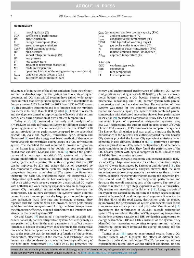
The weather conditions for London, UK, considered as moderateconditions, and Athens, Greece, considered as warm, were used forthe modelling of the alternative system configurations. The ambi-ent temperature variation for these locations was obtained fromWeather Underground [17]. The monthly average temperaturesfor the period July 2015-June 2016 are shown in Fig. 3 with Athens
of CO2 test facilities.
tive CO2 refrigeration system configurations for retail food applications ing/10.1016/j.enconman.2017.03.020
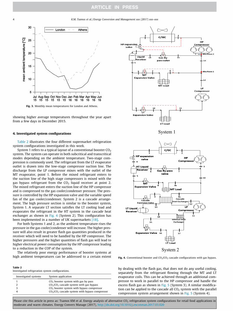
Fig. 3. Monthly mean temperatures for London and Athens.
4 K.M. Tsamos et al. / Energy Conversion and Management xxx (2017) xxx–xxx
showing higher average temperatures throughout the year apartfrom a few days in December 2015.
System 1
System 2 Fig. 4. Conventional booster and CO2/CO2 cascade configurations with gas bypass.
4. Investigated system configurations
Table 2 illustrates the four different supermarket refrigerationsystem configurations investigated in this work.
System 1 refers to a typical layout of a conventional booster CO2
system. The system can operate in both subcritical and transcriticalmodes depending on the ambient temperature. Two-stage com-pression is commonly used. The refrigerant from the LT evaporatoroutlet is drawn into the low-stage compressor suction line. Thedischarge from the LP compressor mixes with the outlet of theMT evaporator, point 1. Before the mixed refrigerant enters tothe suction line of the high stage compressors is mixed with thegas bypass refrigerant from the CO2 liquid receiver at point 2.The mixed refrigerant enters the suction line of the HP compressorand is compressed to the gas cooler/condenser pressure. The pres-sure is controlled by the HP expansion valve and the variable speedfan of the gas cooler/condenser. System 2 is a cascade arrange-ment. The high pressure section is similar to the booster system,System 1. A separate LT section satisfies the LT cooling load andevaporates the refrigerant in the HT system in the cascade heatexchanger as shown in Fig. 4 (System 2). This configuration hasbeen implemented in a number of UK supermarkets [18].
For both Systems 1 and 2, as the ambient temperature rises thepressure in the gas cooler/condenser will increase. The higher pres-sure will also result in greater flash gas quantities produced in thereceiver which will need to be handled by the HP compressor. Thehigher pressures and the higher quantities of flash gas will lead tohigher electrical power consumption by the HP compressor leadingto a reduction in the COP of the system.
The relatively poor energy performance of booster systems athigh ambient temperatures can be addressed to a certain extent
Table 2Investigated refrigeration system configurations.
Investigated systems System application
1 CO2 booster system with gas by pass2 CO2/CO2 cascade system with gas bypass3 CO2 booster system with bypass compressor4 CO2/CO2 cascade system with bypass compressor
Please cite this article in press as: Tsamos KM et al. Energy analysis of alternamoderate and warm climates. Energy Convers Manage (2017), http://dx.doi.or
by dealing with the flash gas, that does not do any useful cooling,separately from the refrigerant flowing through the MT and LTevaporator coils. This can be achieved through an additional com-pressor to work in parallel to the HP compressor and handle theexcess flash gas as shown in Fig. 5 (System 3). A similar modifica-tion can be applied to the cascade all CO2 system with the parallelcompression system arrangement shown in Fig. 5 (System 4).
tive CO2 refrigeration system configurations for retail food applications ing/10.1016/j.enconman.2017.03.020
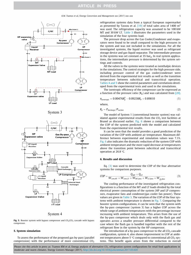
System 3
System 4 Fig. 5. Booster system with bypass compressor and CO2/CO2 cascade with bypasscompressor.
K.M. Tsamos et al. / Energy Conversion and Management xxx (2017) xxx–xxx 5
5. System simulation
To assess the performance of the proposed gas by-pass (parallelcompression) with the performance of more conventional CO2
Please cite this article in press as: Tsamos KM et al. Energy analysis of alternamoderate and warm climates. Energy Convers Manage (2017), http://dx.doi.or
refrigeration systems data from a typical European supermarketas presented by Tassou et al. [19] of total sales area of 1400 m2
was used. The refrigeration capacity was assumed to be 100 kWMT and 30 kW LT. Table 3 illustrates the parameters used in thesimulation of the four systems load.
The pressure drop across the Gas Cooler/Condenser and evapo-rators were found to be small compared to the high pressures inthe system and was not included in the simulations. For all theinvestigated systems, the liquid receiver was used as refrigerantstorage device and gas-liquid separator. The intermediate pressurein the systems was set constant at 35 barg. In real system applica-tions, the intermediate pressure is determined by the system set-tings and controls.
All the valves in the systems were treated as isenthalpic devicesin the simulations. The control strategies for the high pressure side,including pressure control of the gas cooler/condenser werederived from the experimental test results as well as the transitiontemperature between subcritical and transcritical operation.Tables 4 and 5 show the control parameters and correlations devel-oped from the experimental tests and used in the simulations.
The isentropic efficiency of the compressor can be expressed asa function of the pressure ratio (Rp) and was calculated from [20].
gisentropic ¼ 0:00476R2p � 0:09238Rp þ 0:89810 ð1Þ
where,
Rp ¼ Pdischarge=Psuction ð2ÞThe model of System 1 (conventional booster system) was val-
idated against experimental results from the CO2 test facilities atBrunel as discussed earlier. Fig. 6 shows a comparison betweenthe COP of the system predicted with the model and calculatedfrom the experimental test results.
It can be seen that the model provides a good prediction of thevariation of the COP with ambient air temperature. Maximum dif-ference between experimental and simulation values was 7.1%.Fig. 6 also indicates the dramatic reduction of the system COP withambient temperature and the more rapid decrease at temperaturesabove the transition point between subcritical and transcriticaloperation at 26.8 �C.
6. Results and discussion
Eq. (3) was used to determine the COP of the four alternativesystems for comparison purposes.
COP ¼ QMT þ QLT
Wcom;HT þWcom;LT þWMT;fans þWLT;fans þW CGC;fans
ð3Þ
The cooling performance of the investigated refrigeration con-figurations is a function of the MT and LT loads divided by the totalelectrical power consumption of the system (HP and LP compres-sors, evaporator fans and condenser/gas cooler fan power). Thesevalues are given in Table 3. The variation of the COP of the four sys-tems with ambient temperature is shown in Fig. 7. Comparing thebooster system configurations, it can be seen that the system withthe by-pass compressor (system 3) has a higher COP across thewhole range of ambient temperatures with the percentage increaseincreasing with ambient temperature. This arises from the use ofthe by-pass compressor which deals only with the flash gas andoperates across a smaller pressure differential compared to thecase where the flash gas is handled together with the rest of therefrigerant flow in the system by the HP compressor.
The introduction of a by-pass compressor to the all CO2 cascadeconfiguration, system 4, also shows improvement in COP at ambi-ent temperatures above 5 �C compared to conventional all CO2 sys-tems. This benefit again arises from the reduction in overall
tive CO2 refrigeration system configurations for retail food applications ing/10.1016/j.enconman.2017.03.020

Table 3System parameters used in simulations.
MT load LT load
Systems 1 2 3 4 1 2 3 4
Load (kW) 100 100 100 100 30 30 30 30Evaporating temperature (�C) �8 �8 �8 �8 �32 �32 �32 �32Superheat (�C) 10 10 10 10 10 10 10 10Subcooling (�C) 2 2 2 2 – – – –Cascade heat exchanger approach temperature (�C) – – – – 5 5 5 5Evaporator fans, lights, defrost power consumption (kW) 10.5 10.5 10.5 10.5 7 7 7 7Condenser/gas cooler fan power consumption (kW) 7.5 7.5 7.5 7.5 – – – –
Fig. 7. Performance among the four investigated cases.
Fig. 6. Comparison between simulation and experimental results.
Table 4Gas cooler/condenser outlet temperature.
Ambienttemperature range
Gas cooler/condenser outlet temperature
a T_amb < 0 8 �Cb 0 � T_amb � 10 T_amb + DT_appc 10 < T_amb < 26.8 Tcond, ‘‘c” = (�0.0144�(Tamb
2 )) + (1.1264�Tamb) + 9.8272d T_amb =� 26.8 T_amb + DT_app_GC
Table 5Gas cooler/condenser outlet pressure.
Temperaturerange
Condenser/gas cooler temperature outlet
a T_amb < 0 Pout = f(Tout, DTsub)b 0 � T_amb � 10 Pout = f(Tout, DTsub)c 10 < T_amb < 26.8 Pcondenser ‘‘c” = (0.0522�(Tcond, ‘‘c”)2)
�(1.0178�Tcond, ‘‘c”) + 60.798d T_amb � 26.8 Pgas cooler, ‘‘d” = (2.3426* TGC, ‘‘d”) + 11.541
6 K.M. Tsamos et al. / Energy Conversion and Management xxx (2017) xxx–xxx
compressor power consumption of the HP compressors in the sys-tem for similar reasons as system 3.
The energy consumption of the four system configurations forLondon and Athens is shown in Table 6. It can be seen that system3 has the lowest annual energy consumption for both climatic con-ditions, 5% for Athens and 3.6% for London, compared to system 1.
The environmental impacts of a refrigeration system can bedetermined as the sum of direct and indirect GHG emissions. Thedirect carbon dioxide emissions are a result of refrigerant leakagefrom the system. The indirect emissions arise from the emissions
Please cite this article in press as: Tsamos KM et al. Energy analysis of alternamoderate and warm climates. Energy Convers Manage (2017), http://dx.doi.or
generated in the production and transmission of electricity con-sumed by the system. The TEWI (Total Equivalent WarmingImpact) methodology illustrated below was used to assess theenvironmental impact of different refrigeration systems due todirect and indirect carbon dioxide emissions.
TEWI ¼ TEWIDirect þ TEWIIndirect ð4Þ
TEWIDirect ¼ GWP � L � n � þGWP �m � ð1� aÞ ð5Þ
TEWIIndirect ¼ E � b � n ð6ÞGWP for CO2 is 1. ‘‘L” is the annual leakage rate which was
assumed to be 15% [21]. ‘‘n” is the operating lifetime of the refrig-eration systems, assumed for all configurations to be 10 years [21].‘‘m” is the refrigerant charge amount in kilograms for each system.For System 1 and 3 the refrigerant charge was assumed to be1.2 kg/kW cooling load [22]. For Systems 2 and 4 the refrigerantcharge of the HP cascade side was assumed to 1.2 kg/kW loadand for the LP cascade 1 kg/kW load. The direct TEWI calculationstake into account the recycling factor of the refrigerant which wasassumed to be 95% [21]. The indirect TEWI calculations take intoaccount the annual energy consumption (kW h/year) which calcu-lated from the model. The indirect emission factor ‘‘b” was taken as0.72 kgCO2/kW h for Athens [23] and 0.53 kgCO2/kWh for London[24].
Table 7 illustrates the results of the TEWI calculations for thefour system configurations and the two climate conditions.
It can be seen that System 3 has the lowest life cycle TEWI fromall the systems considered, arising primarily from its lowest energyconsumption. The total lifecycle emissions from operation in thewarm climate of Athens are much higher than those for operation
tive CO2 refrigeration system configurations for retail food applications ing/10.1016/j.enconman.2017.03.020

Table 8Annual running cost for the different climate conditions.
System 1 2 3 4
Annual running cost – London (£) 83,166 84,828 80,112 81,385Annual running cost – Athens (£) 104,987 106,726 99,067 101,214
Table 7TEWI results.
System 1 2 3 4
TEWI emissions – London (tonnes CO2) 3061.3 3122.5 2948.9 2995.8TEWI emissions – Athens (tonnes CO2) 4845.9 4926.2 4602.1 4671.8
Table 6Annual energy consumption.
System 1 2 3 4
Annual energy consumption –London (MW h) 577.40 589.08 556.33 565.17Annual energy consumptions-Athens (MW h) 672.99 684.14 639.13 648.80
K.M. Tsamos et al. / Energy Conversion and Management xxx (2017) xxx–xxx 7
in London due to the higher ambient temperatures and compressorpower consumption. The annual electricity running costs of thefour systems are shown in Table 8. Electricity prices were assumedto be £0.144/kW h, for London [25] and £0.156/kW h for Athens[26].
It can be seen that system 3 will result in annual cost savings ofaround £3000 compared to system 1, which is the most commonsystem currently in use, for the London climatic conditions andaround £6000 for the climatic conditions of Athens. For the coolingcapacity of the systems under consideration in this paper, a reason-able estimate of the additional cost for a by-pass compressor sys-tem over the conventional booster refrigeration system will be inthe region of £10,000. The system with the by-pass compressorwill therefore have a payback period of the order of 3 years foroperation at moderate climatic conditions and 2 years for warmclimatic conditions.
7. Conclusions
In this paper, comparative studies of four different CO2 com-mercial refrigeration system configurations have been performed.The evaluation was carried out for moderate and warm weatherconditions and ambient temperatures. The weather conditions ofLondon and Athens were used to represent the moderate andwarm conditions respectively. The following conclusions can bedrawn from the study.
� From the alternative system configurations considered, the CO2
booster system with by-pass compressor (parallel compression)was found to be the most energy efficient system for both themoderate and warm climates. Energy efficiency improvementover the conventional CO2 booster system was found to be inthe region of 5.0% for the warm climate and 3.6% for the mod-erate climate.
� Operation of the CO2 refrigeration system in warm weatherconditions such as those of Athens, Greece, will result in up to16% higher energy consumption compared to the Londonweather conditions.
� The Greenhouse gas emissions from the operation of the sys-tems in Athens will be up to 50% higher than those in Londondue to the higher electrical energy consumption and the higherelectricity generation emission factor for Greece.
Please cite this article in press as: Tsamos KM et al. Energy analysis of alternamoderate and warm climates. Energy Convers Manage (2017), http://dx.doi.or
� By-pass compression in all CO2 booster systems is economicallymore effective in warm weather conditions. The study showedthat payback periods of around 2 years can be achieved in warmweather conditions and 3 years in moderate weatherconditions.
Acknowledgements
This study was supported by the Research Councils UK Energyprogramme, Grant No: EP/K011820/1 and GEA Searle, now Kevlion.The authors wish to acknowledge the cash and in-kind contribu-tions of these organisations as well as the support received fromBrunel University London and the RCUK National Centre for Sus-tainable Energy use in Food Chains (CSEF).
References
[1] Markets and markets. Transcritical CO2 market by application (supermarkets,heat pumps, food processing & storage facilities, ice skating rinks), bygeography (Europe, North America, Asia-Pacific) - global forecast to 2020;2015. Available from www.marketsandmarkets.com [accessed 15/10/15].
[2] Shecco. Market map shows over 6,500 CO2 transcritical stores worldwideAvailable from www.r744.com; 2015 [accessed 15/10/15].
[3] Dubey A, Kumar S, Agrawal G. Thermodynamic analysis of a transcritical CO2/propylene (R744–R1270) cascade system for cooling and heating applications.Energy Convers Manage 2014;86:774–83.
[4] Ommen T, Elmegaard B. Numerical model for thermoeconomic diagnosis incommercial transcritical/subcritical booster systems. Energy Convers Manage2012;60:161–9.
[5] Goodarzi M, Gheibi A. Performance analysis of a modified trans-critical CO2refrigeration cycle. Appl Therm Eng 2015;75:1118–25.
[6] Singh S, Purohit N, Dasgupta M. Comparative study of cycle modificationstrategies for trans-critical CO2 refrigeration cycle for warm climaticconditions. Case Stud Therm Eng 2016;7:78–91.
[7] Ge YT, Tassou SA. Thermodynamic analysis of transcritical CO2 boosterrefrigeration systems in supermarket. Energy Convers Manage2011;52:1868–75.
[8] Gullo P, Elmegaard B, Cortella G. Energy and performance assessment of R744booster supermarket refrigeration systems operating in warm climates. Int JRefrigeration 2016;64:61–79.
[9] Beshr M, Aute V, Sharma V, Abdelaziz O, Fricke B, Radermacher R. Acomparative study on the environmental impact of supermarketrefrigeration systems using low GWP refrigerants. Int J Refrigeration2015;56:154–64.
[10] Sharma V, Fricke B, Bansal P. Comparative analysis of various CO2configurations in supermarket refrigeration systems. Int J Refrigeration2014;46:86–99.
[11] Fazelpour F, Morosuk T. Exergoeconomic analysis of carbon dioxidetranscritical refrigeration machine. Int J Refrigeration 2014;38:128–39.
tive CO2 refrigeration system configurations for retail food applications ing/10.1016/j.enconman.2017.03.020

8 K.M. Tsamos et al. / Energy Conversion and Management xxx (2017) xxx–xxx
[12] Bai T, Yu J, Yan G. Advanced exergy analyses of an ejector expansiontranscritical CO2 refrigeration system. Energy Convers Manage2016;126:850–61.
[13] Mosaffa A, Farshi LG, Ferreira CAI, Rosen MA. Exergoeconomic andenvironmental analyses of CO2/NH3 cascade refrigeration systems equippedwith different types of flash tank intercoolers. Energy Conver Manage2016;117:442–53.
[14] Ge YT, Tassou SA, Santosa ID, Tsamos K. Design optimisation ofCO2 gas cooler/condenser in a refrigeration system. Appl Energy 2015;160:973–81.
[15] Tsamos KM, Ge YT, Santosa IDMC, Tassou SA. Experimental investigation of gascooler/condenser designs and effects on a CO2 booster system. Appl Energy2017;186:470–9.
[16] IDewa Santosa, Gowreesunker B, Tassou S, Tsamos K, Yunting G. Investigationsinto air and refrigerant side heat transfer coefficients of finned-tube CO2 gascoolers. Int J Heat Mass Transfer 2017;107:168–80.
[17] TWC. The weather company, LLC - weather underground; 2016. Available on:https://www.wunderground.com/ [accessed 04/07/16].
[18] Campbell A. Working with CO2 supermarkets; 2009. Available from: http://www.atmosphere2009.com/speakers.presentations.php [accessed 14/01/2013].
Please cite this article in press as: Tsamos KM et al. Energy analysis of alternamoderate and warm climates. Energy Convers Manage (2017), http://dx.doi.or
[19] Tassou A, Lewis J, Ge YT, Hasawey A, Chaer I. A review of emergingtechnologies for food refrigeration applications. Appl Therm Eng2010;30:263–76.
[20] Lee TS, Liu CH, Chen TW. Thermodynamic analysis of optimal condensingtemperature of cascade refrigeration systems. Int J Refrigeration2006;29:1100–8.
[21] UNEP. Report of the refrigeration, air conditioning and heat pumps technicaloptions committee; 2014. 243 p.
[22] Shilliday JA. Investigation and optimisation of commercial refrigeration cyclesusing the natural refrigerant CO2. PhD Thesis – Brunel University; 2012.Available from: http://bura.brunel.ac.uk/handle/2438/7454 [accessed: 10/10/2013].
[23] International energy agency. CO2 Emissions from fuels combustion highlights;2015. 152 p. Available from: https://www.iea.org [accessed: 10/08/2016].
[24] Carbon Trust. Carbon trust conversion factors: energy and carbon conversions2011 update Available at: http://www.carbontrust.com; 2011 [accessed 10/08/16].
[25] U-switch, 2016. Available on: https://www.uswitch.com/gas-electricity/consumptions/new [accessed: 16/08/2016].
[26] Helppost, 2016. Available on: http://www.helppost.gr/dei/ypologismos-reuma-katanalosi/ [accessed: 16/08/2016].
tive CO2 refrigeration system configurations for retail food applications ing/10.1016/j.enconman.2017.03.020


![Introduction - Open Access Brunelbura.brunel.ac.uk/bitstream/2438/14264/2/FullText.docx · Web view“Complicity” is a key word, ... [sabotage] and reprisal. Not ... served as](https://static.fdocuments.us/doc/165x107/5a77ebc77f8b9aea3e8e6751/introduction-open-access-brunelburabrunelacukbitstream2438142642fulltextdocx.jpg)

![Paper Title (use style: paper title) - Open Access Brunelbura.brunel.ac.uk/bitstream/2438/11690/1/Fulltext.docx · Web viewH. X. Zhang et al. in [101], presented the improved full](https://static.fdocuments.us/doc/165x107/5aeb51f57f8b9a36698e31bb/paper-title-use-style-paper-title-open-access-viewh-x-zhang-et-al-in-101.jpg)